Digi 50M1699 WLAN Module User Manual CC Wi i MX51 HRM
Digi International Inc WLAN Module CC Wi i MX51 HRM
Digi >
Contents
- 1. User Manual Part1
- 2. User Manual Part2
- 3. User Manual Part3
- 4. User Manual Part4
- 5. User Manual
User Manual Part4

ConnectCorefori.MX51
©2010DigiInternational,Inc. 111
By default, serial port 1 signals are configured as GPIO signals.
Serial Port 3, TTL Interface, X19
The serial (UART) port 3 interface is a TTL interface connected to a 2x5 pin, 2.54mm
connector, X19. The connector supports only TTL level signals.
The serial port 3 interface is connected to i.MX51 UART port 3.
Serial port 3 pins are allocated as shown:
By default, serial port 3 signals are configured to their respective GPIO or KEY_COL signals.
Serial port 3 is connected to the X19 connector and to the XBee module socket. Two jumpers
(J30 and J31) are used in the development board to select the connector where serial port 3
will be available. Refer to the “Jumpers” section of this document for more information.
By default serial port 3 CTS# signal is not connected to X19. A 0Ω resistor, R44, must be
manually populated to connect this signal to the X19 connector.
Pin Function Defaults to
1NC -
2NC -
3 RXD GPIO1_22
4 RTS# KEY_COL4
5 TXD GPIO1_23
6 CTS# KEY_COL5
7NC -
8NC -
9GND -
10 +3.3V -
ConnectCorefori.MX51
©2010DigiInternational,Inc. 112
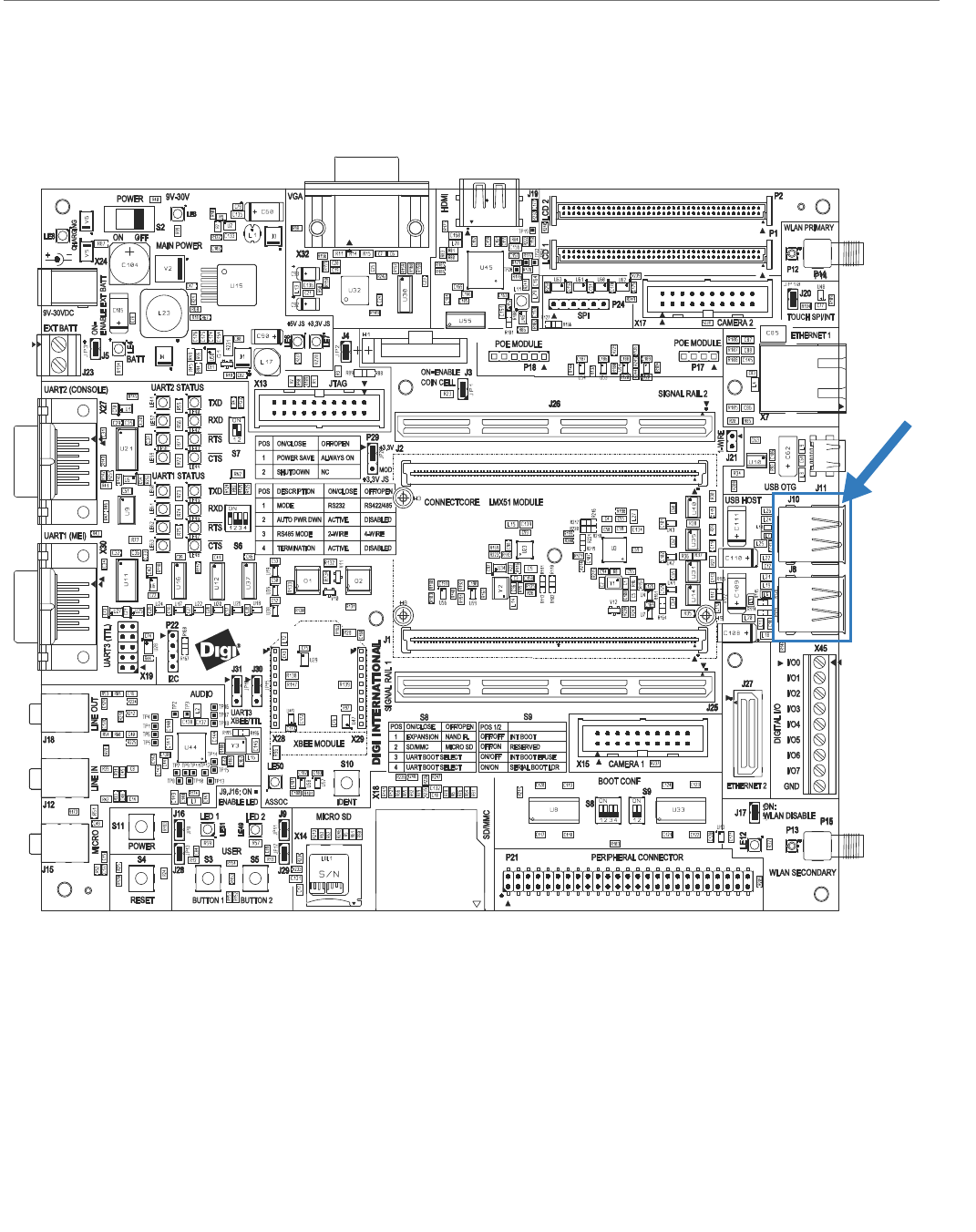
USB Host Interface
USB Host Connectors, J8 and J10
The development board provides four standard type A receptacles for a USB host connection.
A 4-Port USB hub is used in the development board to convert the USB host port 1 of the
module into four USB host ports. The module supports low, full and high speed USB 2.0
connectivity.
USB Host
Connectors,
J8 & J10
ConnectCorefori.MX51
©2010DigiInternational,Inc. 113
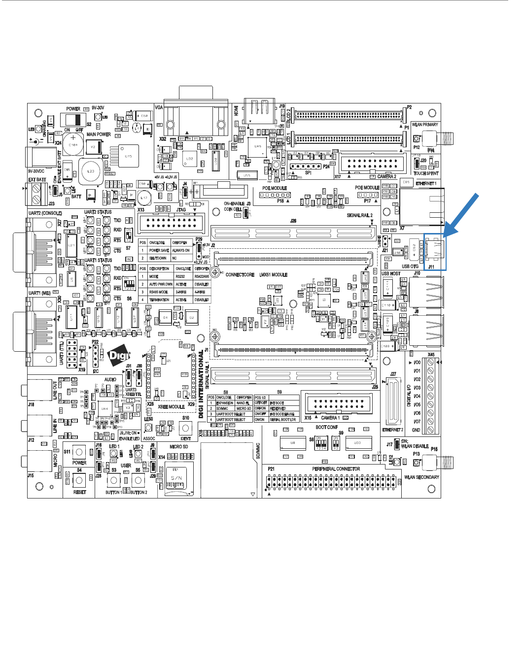
USB OTG Interface
USB OTG Connector, J11
The development board provides a standard mini-AB type receptacle for a USB OTG
connection. The module supports full and high speed USB2.0 connectivity.
USB OTG
Connector,
J11
ConnectCorefori.MX51
©2010DigiInternational,Inc. 114
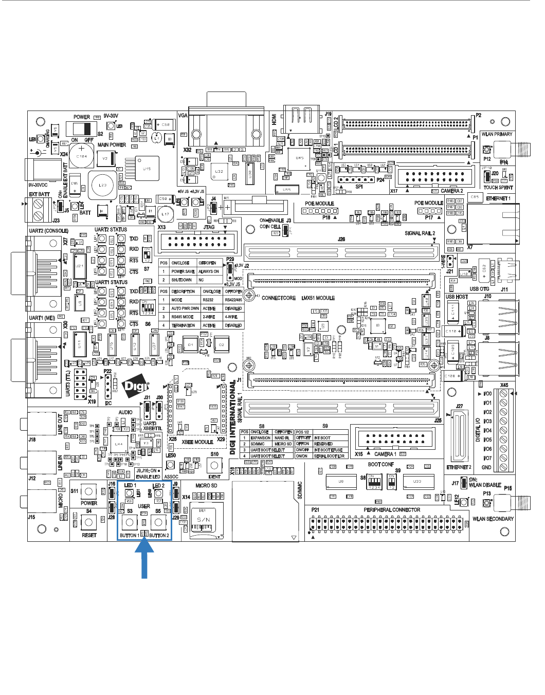
User Interface
The development board provides two user buttons and two user LEDs connected to GPIO
signals of the i.MX51.
The user buttons and the user LEDs can be enabled or disabled by correctly setting the
corresponding jumpers.
User Interface

ConnectCorefori.MX51
©2010DigiInternational,Inc. 115
The table below shows the GPIO signal assigned to the user interface, and the jumpers used
to enable/disable the buttons and LEDs:
Signal GPIO Jumper Comment
USER_BUTTON1 GPIO3_6 J28 10K pull-up to +2.775V on the development board
USER_LED1# GPIO3_10 J16
USER_BUTTON2 GPIO1_1 J29 10K pull-up to +2.775V on the development board
USER_LED2# GPIO3_9 J9
ConnectCorefori.MX51
©2010DigiInternational,Inc. 116
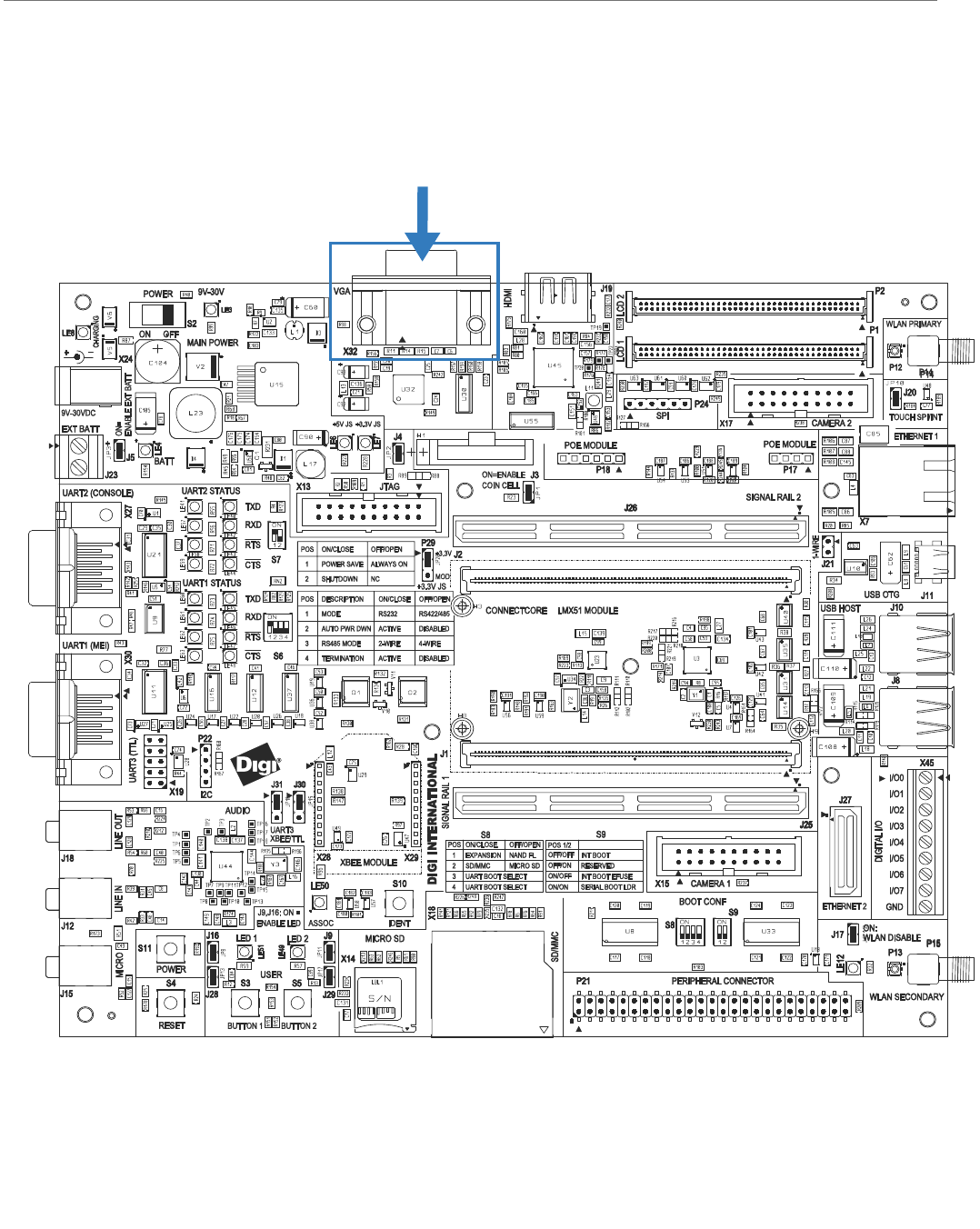
Analog Video Interface
VGA Connector, X32
ConnectCorefori.MX51
©2010DigiInternational,Inc. 117
Analog Video Connector, X32
The development board provides an Analog Video connector. This connector is a 15-pin
female connector, labeled X32. The Analog Video interface is connected to the Display 1
interface of the i.MX51 CPU.
The table below shows the pinout of the Analog Video connector.
Pin Signal
1VGA_RED
2 VGA_GREEN
3VGA_BLUE
4NC
5GND
6 RED_RETURN
7 GREEN_RETURN
8 BLUE_RETURN
9NC
10 GND
11 NC
12 NC
13 HSYNC#
14 VSYNC#
15 NC
ConnectCorefori.MX51
©2010DigiInternational,Inc. 118
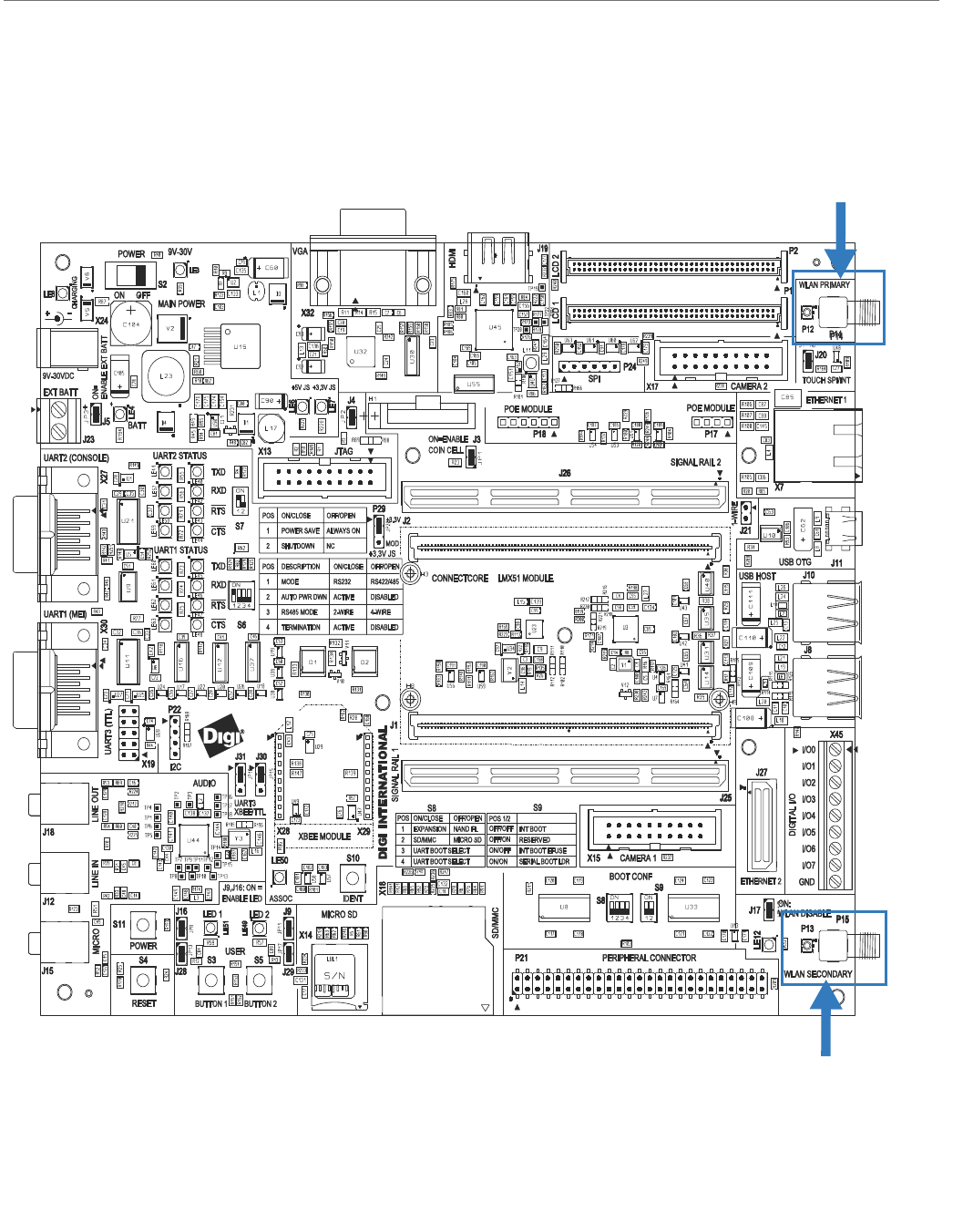
WLAN Interface
Primary Antenna
Connectors, P12 & P14
Secondary Antenna
Connectors, P13 & P15
ConnectCorefori.MX51
©2010DigiInternational,Inc. 119
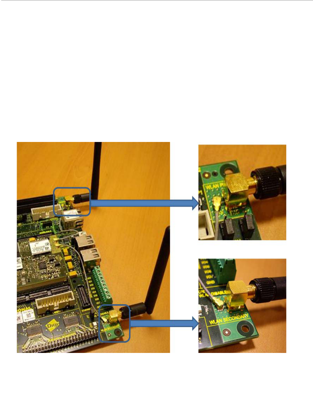
Antenna Connectors (WLAN)
The development board provides the following connectors for the WLAN interface:
P12 and P13: these two UFL connectors are used to connect the WLAN interface of the
ConnectCore for i.MX51 to the development board. Two coaxial cables are used for
this connection.
P14 and P15: these two RP-SMA connectors are used to connect two (primary and
secondary) WLAN antennas
The following picture shows the WLAN antenna connections.
ConnectCorefori.MX51
©2010DigiInternational,Inc. 120
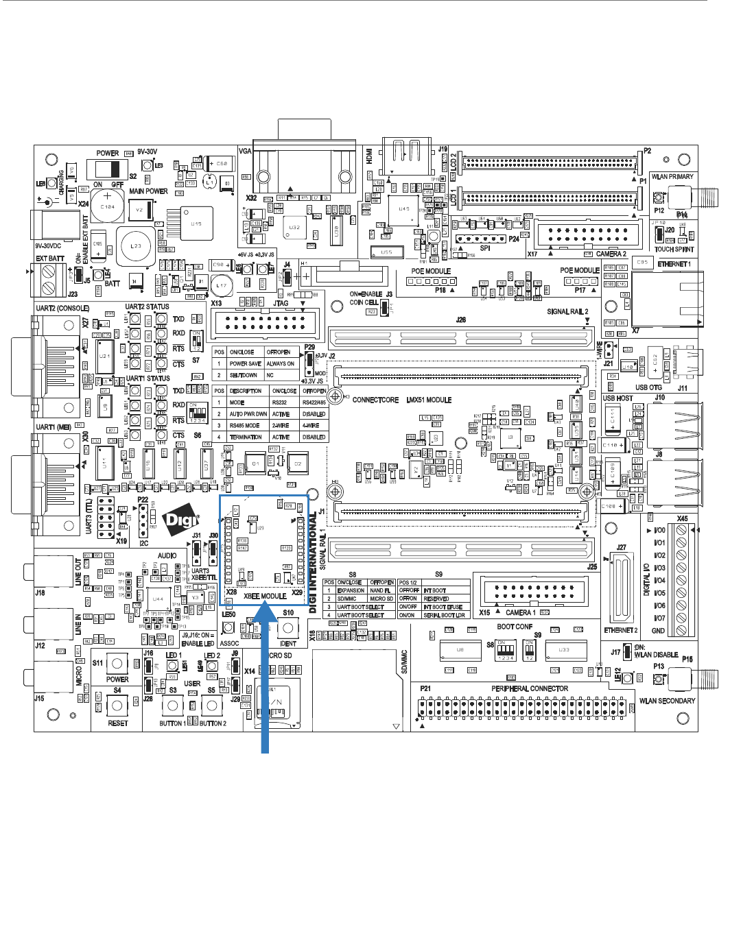
Digi XBee TM Interface
Digi XBee
Connectors, X28 & X29
ConnectCorefori.MX51
©2010DigiInternational,Inc. 121
Digi XBeeTM Module Connectors, X28 and X29
The development board provides two 10-pin, 2.0mm connectors, X28 and X29, supporting a
Digi XBee module.
The XBee serial port is shared with UART port 3 on the development board. Two jumpers (J30
and J31) are used in the development board to select the connector where serial port 3 will
be available. Refer to the “Jumpers” section of this document for more information.
The table below shows the pinout of the XBee module connectors.
Pin Signal Pin Signal
X28-1 +3.3V X29-1 IDENT
X28-2 XBEE_DOUT X29-2
X28-3 XBEE_DIN X29-3
X28-4 NC X29-4
X28-5 XBEE_RESET# X29-5 XBEE_RTS#
X28-6 - X29-6 ASSOC
X28-7 - X29-7
X28-8 - X29-8 ON/SLEEP#
X28-9 XBEE_SLEEP_RQ X29-9 XBEE_CTS#
X28-10 GND X29-10
©2010DigiInternational,Inc. 122
Module Specifications
APPENDIX A
This appendix provides ConnectCore for i.MX51 module specifications.

ConnectCorefori.MX51
©2010DigiInternational,Inc. 123
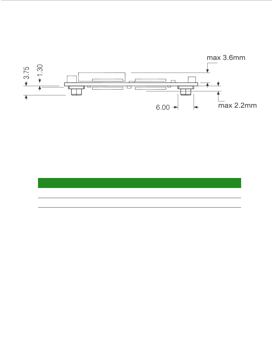
Mechanical Specifications
Environmental Specifications
Length: 82 mm (3.228 inches)
Width: 50 mm (1.968 inches)
Height :
–PCB: 1.40 mm (0.055 inches)
–Top side part: 3.60 mm (0.142 inches)
–Bottom side part: 2.20 mm (0.087 inches)
Operating temperature: 600MHz variant:
-40ºC to +85ºC (-40ºF to +185ºF)
800MHz variant:
0ºC to +70ºC (32ºF to +158ºF)
Storage temperature: -40ºC to +125ºC (-40ºF to +257ºF)
ConnectCorefori.MX51
©2010DigiInternational,Inc. 124
Network Interface
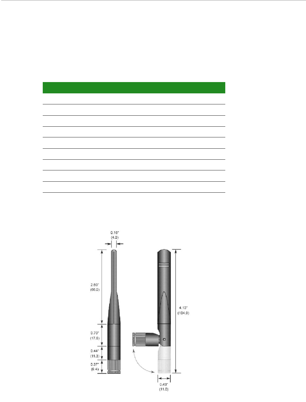
Antenna specifications: 802.11 a/b/g antenna
Attributes
Dimensions
Note:
Dimensions are provided for reference purposes only. The actual antenna might vary.
Attribute Band 1 Band 2
Frequency 2.4 ~ 2.4835 GHz 5.15 ~ 6 GHz
Bandwidth 120MHz 875MHz
Wavelength 1/4 Wave 1/4 Wave
Impedance 50 Ohm 50 Ohm
VSWR < 19 typ. Center < 19 typ. Center
Connector RP-SMA RP-SMA
Gain 2.3dBi 3.6dBi
Dimension See measurements in the drawing after this table
Part Number ANT-DB1-RAF-RPS
ConnectCorefori.MX51
©2010DigiInternational,Inc. 125
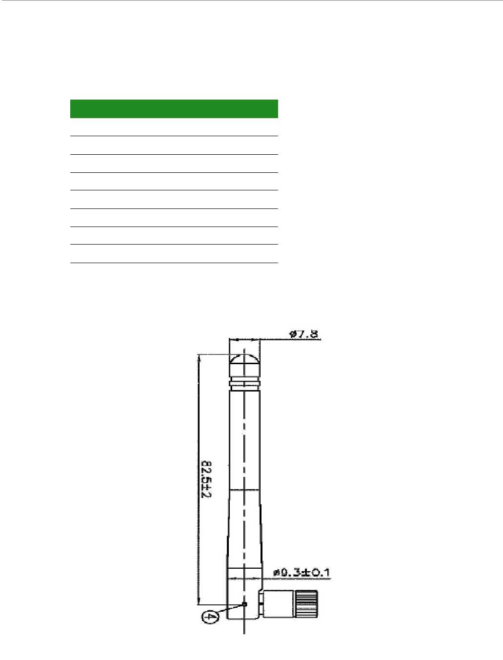
Antenna Specification: 802.11b/g antenna
Attributes
Dimensions
Note:
Dimensions are provided for reference purposes only. The actual antenna might vary.
Attribute Property
Frequency 2.4 ~ 2.5GHz
Power Output 2W
DB Gain 2dBi
VSWR < or = 2.0
Dimension 108.5 mm % 10.0mm
Weight 10.5g
Temperature Rating -40 °to +80° C
Part Number DG-ANT-20DP-BG

ConnectCorefori.MX51
©2010DigiInternational,Inc. 126
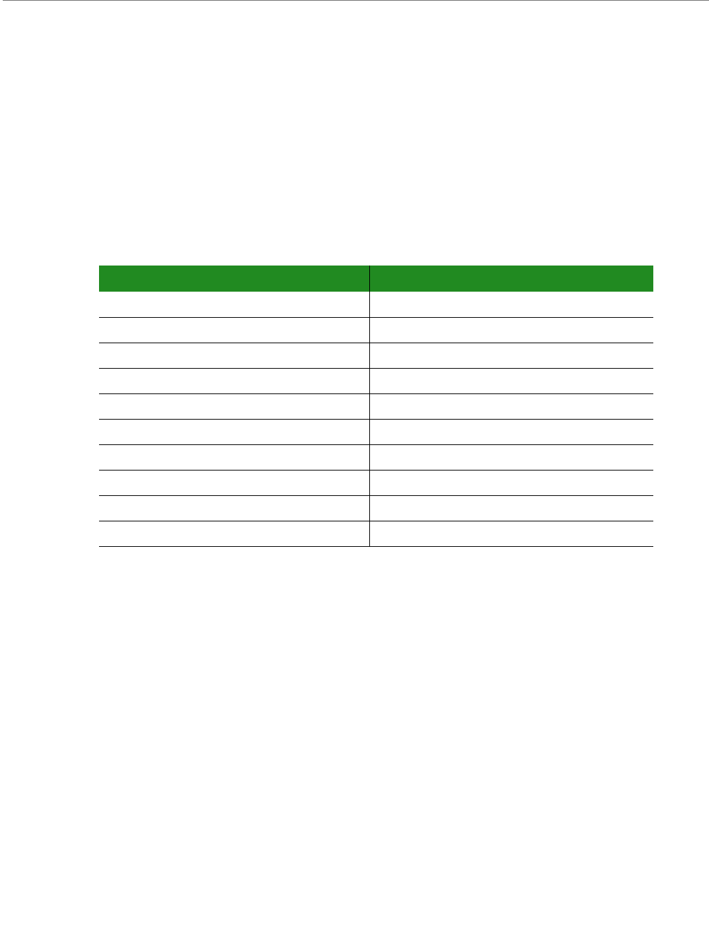
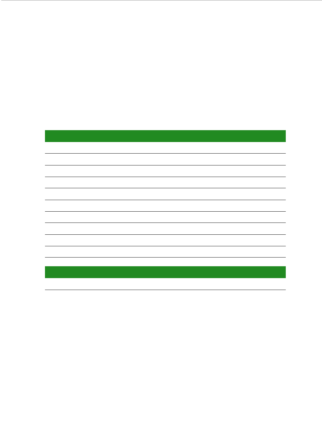
Ethernet 1
Ethernet 2
Standard: IEEE 802.3/802.3u
Physical layer: 10/100Base
Data rate: 10/100 Mbps
Mode: Full or half duplex
Standard: IEEE 802.3/802.3u
Physical layer: 10/100Base
Data rate: 10/100 Mbps
Mode: Full or half duplex

ConnectCorefori.MX51
©2010DigiInternational,Inc. 127
WLAN
Standard
IEEE 802.11a/b/g/e/i/h/j standards
Single-stream IEEE 802.11n
Frequency Band
2.400 - 2.500 GHz ( Low Band )
4.900 - 5.850 GHz ( High Band )
Data Rates
802.11n :6.5, 13, 19.5, 26, 39,52 , 58.5, 65 Mbps
802.11a/g :6, 9, 12, 18, 24, 36, 48, 54 Mbps
802.11b :1, 2, 5.5, 11 Mbps
Media Access Control
Dynamic selection of fragment threshold, data rate and antenna depending on the
channel statistics
WPA, WPA2 and WMM support
Wireless Medium
802.11b/g : Direct Sequence-Spread Spectrum ( DSSS ) and Orthogonal Frequency
Divisional Multiplexing ( OFDM )
802.11a/n : OFDM
DFS Client
This module supports the DFS Client only between 5.25 and 5.35GHz bands. It does
not support being DFS Master, or can it be connected to an Ad hoc network in these
bands.

ConnectCorefori.MX51
©2010DigiInternational,Inc. 128
Modulation DSSS
Differential Binary Shift Keying ( DBPSK ) @ 1 Mbps
Differential Quadrature Phase Shift Keying ( DQPSK ) @2 Mbps
Complementary Code Keying ( CCK ) @ 5.5 Mbps and 11 Mbps
BPSK @ 6 and 9 Mbps
QPSK @ 12 and 18 Mbps
16-Quadrature Amplitude Modulation ( QAM ) @24 and 36 Mbps
64-QAM @ 48 and 54 Mbps
Frequency Bands
2.412 to 2.472 GHz ( ETSI )
2.412 to 2.462 GHz ( FCC )
5.150 to 5.250 GHz ( ETSI ) ISM Band 1
5.250 to 5.350 GHz ( ETSI ) ISM Band 2 excluding TPC and DFS Client
5.470 to 5.725 GHz ( ETSI ) ISM Band 3 excluding TPC and DFS Client
5.150 to 5.250 GHz ( U-NII-1 )
5.250 to 5.350 GHz ( U-NII-2 )
5.470 to 5.725 GHz ( U-NII Worldwide )
5.725 to 5.825 GHz ( U-NII-3 )
Available Transmit Power Settings ( Typical +- ( 2 dBm )@25°C)
( Maximum power settings will vary according to individual country regulations. )
IEEE 802.11b ( ~16mW ETSI ) ( ~37mW FCC 15.247 )
@ 1, 2, 5.5 and 11 Mbps
IEEE 802.11g ( ~ 10mW ETSI ) ( ~72mW FCC 15.247 )
@ 6, 12, 18, 24, 36 and 54Mbps
IEEE 802.11n 2.4GHz Band ( ~12.5mW ETSI ) ( ~83mW FCC 15.247 )
IEEE 802.11a & IEEE 802.11n
( ~15mW ETSI )
( 5.150 to 5.250 GHz ~17mW FCC 15.407 )
ConnectCorefori.MX51
©2010DigiInternational,Inc. 129
( 5.250 to 5.350 GHz ~17mW FCC 15.407 )
( 5.470 to 5.725 GHz ~22mW FCC 15.407 )
( 5.725 to 5.850 GHz ~28mW FCC 15.247 )
@ 6, 12, 18, 24, 36 and 54Mbps and
@ 6.5, 13, 19.5, 26, 39,52 , 58.5, 65 Mbps
Receive Sensitivity
Data Rate (bg Mode) Typical Sensitivity (+ / - 1.5 dBm)
1 Mbps -94.0 dBm (< 8% PER)
2 Mbps -89.0 dBm (< 8% PER)
11 Mbps -86.0 dBm (< 8% PER)
6 Mbps -89.0 dBm (< 10% PER)
54 Mbps -74.0 dBm (< 10% PER)
645Mbps -71.0 dBm (< 10% PER)
Data Rate (a Mode) Typical Sensitivity ( + / - 1.5 dBm)
6 Mbps -88.0 dBm (< 10% PER)
54 Mbps -72.0 dBm (< 10% PER)
Data Rate (bg Mode) Typical Sensitivity (+ / - 1.5 dBm)
65 Mbps -69.0 dBm (< 10% PER)

ConnectCorefori.MX51
©2010DigiInternational,Inc. 130
Electrical Characteristics
Supply Voltages
Supply Current
The following table provides current draw guidance utilizing the power management
capabilities of the module. The module variant used for the measurements works at 800MHz,
with 512 MB NAND Flach, 512 MB DDR2, dual Ethernet, WLAN, and accelerometer. A Windows
Embedded CE kernel with power management capabilities has been used to make the current
consumption measurements. A different kernel (Linux or Windows CE) with a different driver
configuration will show different current consumption values.
The ConnectCore for 1.MX51 module can be powered from an external battery (VLIO) or from
a battery charger (VCHRG). Current drawn by the modules is different depending on the
supply voltage used. The following tables show the current drawn by the module from the
two power supplies.
The current drawn by the module is highly dependent on the number and type of interfaces
used. To make some current measurements three different interface configurations have
been defined:
Parameter Symbol Min Typ Max Unit
Battery Input VLIO 3.4 3.7 4.8 V
Charger Input VCHRG 3.4 520 V
Coin cell Input for RTC VCC_COINCELL 2.5 33.6 V
Interface Configuration Interfaces Used
Minimum Console, Ethernet.
+3.3V of development board drawn from external power supply.
Typical VGA, USB Host (two devices connected), Audio, Ethernet, Console.
+3.3V of development board drawn from module.
Maximum Display1, Display2, Camera1, Camera2, USB OTG, USB Host (four devices
connected), Audio, Ethernet, Console, WLAN, SD Card, microSDTM Card.
+3.3V of development board drawn from module.
ConnectCorefori.MX51
©2010DigiInternational,Inc. 131
The ConnectCore for 1.MX51 supports several power modes. The current drawn by the
module is highly dependent on the power modes. To make some current measurements five
different power modes have been defined:
The tables below show the current drawn by the module for the different power modes and
the different interface configurations.
Current measurement in Minimum configuration
Interface Configuration Interfaces Used
Full Load System running at 100% CPU load.
Normal Normal operating state. User interacting with the device.
User Idle After a long period of user inactivity some devices are turned off.
System Idle In this state the user is not using the system, even passively, and devices that are
not actively doing work are turned off.
Suspend This is the sleep state, no threads are running, the CPU is idle, the peripherals are
turned off, and the system can wake up only by means of hardware wake-source
interrupt.
Power Mode Power Supply Current Draw Comments
Full load +3.7V Battery 700mA
+5V supply to charger 680mA
ON +3.7V Battery 420mA
+5V supply to charger 410mA
User Idle +3.7V Battery 420mA
+5V supply to charger 410mA
System Idle +3.7V Battery 380mA
+5V supply to charger 390mA
Suspend +3.7V Battery 145mA
+5V supply to charger 170mA
ConnectCorefori.MX51
©2010DigiInternational,Inc. 132
Current measurement in Typical configuration
Current measurement in Maximum configuration
Power Mode Power Supply Current Draw Comments
Full load +3.7V Battery 1450mA
+5V supply to charger 1250mA
ON +3.7V Battery 1150mA
+5V supply to charger 950mA
User Idle +3.7V Battery 1075mA
+5V supply to charger 890mA
System Idle +3.7V Battery 350mA
+5V supply to charger 350mA
Suspend +3.7V Battery 145mA
+5V supply to charger 170mA
Power Mode Power Supply Current Draw Comments
Full load +3.7V Battery 2100mA
+5V supply to charger 1850mA
ON +3.7V Battery 1900mA
+5V supply to charger 1700mA
User Idle +3.7V Battery 1800mA
+5V supply to charger 1650mA
System Idle +3.7V Battery 1600mA
+5V supply to charger 1250mA
Suspend +3.7V Battery 420mA
+5V supply to charger 490mA

ConnectCorefori.MX51
©2010DigiInternational,Inc. 133
On-Module Power Supplies
The following table provides the on-module power supplies available in the module
connectors, used to supply the components integrated on a customer baseboard.
I/O DC Parameters
This section includes the DC parameters of the following I/O types:
General Purpose I/O and High-Speed General Purpose I/O (GPIOxx/HSGPIOxx)
Low Voltage I/O (LVIO)
Ultra High Voltage I/O (UHVIOxx)
WLAN
PMIC_GPO, PMIC_PWRON, PMIC_STDBY, PMIC_INT, PMIC_PWDRV, PMIC_SE,
PMIC_CHRGLED, and PMIC_LED
Ethernet (ETH)
Analog RGB
ADC subsystem (ADIN)
Digital and analog USB (DIG_USB, AN)USB)
The I/O type associated to each I/O signal of the module is shown in the paragraph “Module
Pinout” of Chapter 1.
Supply Source Output Voltage Load Capacity Comments
+2.775V PMIC
VIOHI LDO
+2.775V 100mA max Used on module to power IPU, Peripheral
interfaces, Accelerometer, I2C, and
bootstraps
+1.8V PMIC
Buick Switcher
+1.8V 800mA max Used on module to power EMI, JTAG and
boot configuration
+3.3V DC/DC
Converter
+3.3V 1A max Used on module to power WLAN,
Ethernet and MII PHY
+3.15V PMIC
VGEN2 LDO
+3.15V 350mA maz Used on module to power NAND Flash
SD1 and fuse interface
SWBST PMIC +5V
Boot Switcher
+5V 300mA max
ConnectCorefori.MX51
©2010DigiInternational,Inc. 134
The following table shows the General Purpose I/O and High-Speed General Purpose I/O
(GPIOxx/HSGPIOxx) DC parameters. The “xx” reference signifies the supply voltage level.
Parameter Symbol Min Typ Max Unit
Supply Voltage VDD
xx = 18
xx = 27
xx = 33
1.65
2.5
3.0
1.8
2.775
3.3
1.95
3.1
3.6
V
High-level output voltage Voh
(Vol USB)
VDD-0.15
VDD-0.43
-
-
VDD+0.3
VDD+0.3 V
Low-level output voltage Vol
(Vol USB)
-
---
0.15
0.43 V
High-level output current Ioh
- Low drive
- Medium drive
- High drive
- Max drive
-1.9
-3.7
-5.2
-5.6
--
mA
Low-level output current Iol
- Low drive
- Medium drive
- High drive
- Max drive
1.9
3.7
5.2
5.6
--
mA
High-level input voltage VIH 0.7 x VDD - VDD V
Low-level input voltage VIL 0 - 0.3 x VDD V
Input Current (no/pull) Iin - - 2 µA
Input Current (22kΩ/pull-up) Iin - - 161 µA
Input Current (47kΩ/pull-up) Iin - - 76 µA
Input Current (100kΩ/pull-up) Iin - - 36 µA
Input Current (100kΩ/pull-down) Iin - - 36 µA
Keeper circuit resistance - - 17 - kΩ
Output driver impedance Rout
- Low drive
- Medium drive
- High drive
- Max drive
80
40
27
20
104
52
35
26
250
125
83
62
Ω
ConnectCorefori.MX51
©2010DigiInternational,Inc. 135
The following table shows the LVIO DC parameters.
Parameter Symbol Min Typ Max Unit
Supply Voltage VDD 1.65 1.8 1.95 V
High-level output voltage Voh VDD-0.15 - - V
Low-level output voltage Vol - - 0.15 V
High-level output current Ioh
- Low drive
- Medium drive
- High drive
- Max drive
-2.1
-4.2
-6.3
-8.4
--
mA
Low-level output current Iol
- Low drive
- Medium drive
- High drive
- Max drive
2.1
4.2
6.3
8.4
--
mA
High-level input voltage VIH 0.7 x VDD - VDD V
Low-level input voltage VIL 0 - 0.3 x VDD V
Input Current (no/pull) Iin - - 1 µA
Input Current (22kΩ/pull-up) Iin - - 161 µA
Input Current (47kΩ/pull-up) Iin - - 76 µA
Input Current (100kΩ/pull-up) Iin - - 36 µA
Input Current (100kΩ/pull-down) Iin - - 36 µA
Keeper circuit resistance - - 17 - kΩ
Output driver impedance Rout
- Low drive
- Medium drive
- High drive
- Max drive
80
40
27
20
150
75
51
38
250
125
83
62
Ω

ConnectCorefori.MX51
©2010DigiInternational,Inc. 136
The following table shows the Ultra-High Voltage I/O (UHVIOxx) DC parameters. The “xx”
reference signifies the supply voltage level.
Parameter Symbol Min Typ Max Unit
Supply Voltage VDD
xx = 31
xx = 33
3.0
3.0
3.15
3.3
3.6
3.6
V
High-level output voltage Voh
(USB, WLAN)
VDD-0.15
VDD-0.43
-
-
VDD-0.15
VDD-0.43
V
Low-level output voltage Vol
(USB, WLAN)
-
---
0.15
0.43
V
High-level output current Ioh
- Low drive
- Medium drive
- High drive
-5.1
-10.2
-15.3
--
mA
Low-level output current Iol
- Low drive
- Medium drive
- High drive
5.1
10.2
15.3
--
mA
High-level input voltage VIH 0.7 x VDD - VDD V
Low-level input voltage VIL 0 - 0.3 x VDD V
Input Current (no/pull) Iin - - 10 µA
Input Current (22kΩ/pull-up) Iin - - 202 µA
Input Current (75kΩ/pull-up) Iin - - 61 µA
Input Current (100kΩ/pull-up) Iin - - 47 µA
Input Current (360kΩ/pull-down) Iin - - 5.7 µA
Keeper circuit resistance - - 17 - kΩ
Output driver impedance Rout
- Low drive
- Medium drive
- High drive
114
57
38
135
67
45
206
103
69
Ω
ConnectCorefori.MX51
©2010DigiInternational,Inc. 137
The following table shows the WLAN DC parameters.
The following table shows the PMIC_GPO DC parameters.
The following table shows teh PMIC_PWRON DC parameters.
The following table shows the PMIC_STDBY DC parameters.
Parameter Symbol Min Typ Max Unit
Supply Voltage VDD 3.0 3.3 3.6 V
High-level output voltage Voh 2.4 - VDD V
Low-level output voltage Vol - - 0.4 V
High-level input voltage VIH 2 - 5.5 V
Low-level input voltage VIL -0.3 - 0.8 V
Input Leakage Current I1K - - 10 µA
Parameter Symbol Min Typ Max Unit
Supply Voltage VDD 2.5 2.775 3.1 V
High-level output voltage Voh VDD-0.2 - VDD V
Low-level output voltage Vol - - 0.2 V
Output driver impedance Rout 200 - 500 Ω
Parameter Symbol Min Typ Max Unit
Supply Voltage VDD - 1.5 3.1 V
High-level input voltage Vih 1 - VDD V
Low-level input voltage Vil - - 0.3 V
Input pull-up impedance Rup - 200 - kΩ
Parameter Symbol Min Typ Max Unit
High-level output voltage Voh 1 - 3.6 V
Low-level output voltage Vol - - 0.3 V
Input pull-down impedance Rdw - 36 - MΩ
ConnectCorefori.MX51
©2010DigiInternational,Inc. 138
The following table shows the PMIC_INT DC parameters.
The following table shows the PMIC_PWGTDRV DC parameters.
The following table shows the PMIC_LED DC parameters.
The following table shows the PMIC_SE DC parameters.
The following table shows the Ethernet DC parameters.
Parameter Symbol Min Typ Max Unit
Supply Voltage VDD 2.5 2.775 3.1 V
High-level output voltage Voh VDD-0.2 - VDD V
Low-level output voltage Vol - - 0.2 V
Output driver impedance Rout 200 - 500 Ω
Parameter Symbol Min Typ Max Unit
High-level output voltage Voh 5 5.4 5.4 V
Low-level output voltage Vol - - 0.1 V
Load Current Iout - - 100 nA
Parameter Symbol Min Typ Max Unit
Input current Iled 0 - 21 mA
Parameter Symbol Min Typ Max Unit
Supply Voltage VDD 2.5 2.775 3.1 V
High-level output voltage Voh 1 - VDD V
Low-level output voltage Vol - - 0.3 V
Input pull-up impedance Rup - 100 - kΩ
Parameter Symbol Min Typ Max Unit
Differential Output Voltage High
100BASE-Tx
Vpph 950 - 1050 mV
Differential Output Voltage Low
100BASE-Tx
Vppl -950 - -1050 mV
ConnectCorefori.MX51
©2010DigiInternational,Inc. 139
The following table shows the Analog RGB DC parameters.
The following table shows the DC parameter of the ADC subsystem. The ADC subsystem is
used by the touch interface and by the three analog input signals (ADIN).
The following table shows the DC parameter of the digital USB.
The following table shows the DC parameter of the Analog USB.
Tx Differential Output Voltage
10BASE-T
Vout 2.2 2.5 2.8 V
Rx Differential Squelch Threshold
10BASE-T
Vds 300 420 585 mV
Parameter Symbol Min Typ Max Unit
Supply Voltage VDD 2.69 2.75 2.91 V
Parameter Symbol Min Typ Max Unit
Input Voltage range VI 0 - 2.4 V
Input Buffer offset Voff -5 - 5 mV
Conversion Current Iin - 1 - mA
Source Impedance Rin - - 5 kΩ
Parameter Symbol Min Typ Max Unit
Supply Voltage VDD 2.25 2.5 2.75 V
High-level output voltage Voh VDD-0-.43 - VDD V
Low-level output voltage Vol - - 0.43 V
High-level input voltage VIH 0.7 x VDD - VDD V
Low-level input voltage VIL 0 - 0.3 x VDD V
Current consumption I - - 22 mA
Parameter Symbol Min Typ Max Unit
Supply Voltage VDD 3.0 3.3 3.6 V
Current consumption I - - 6 mA
Parameter Symbol Min Typ Max Unit
©2010DigiInternational,Inc. 140
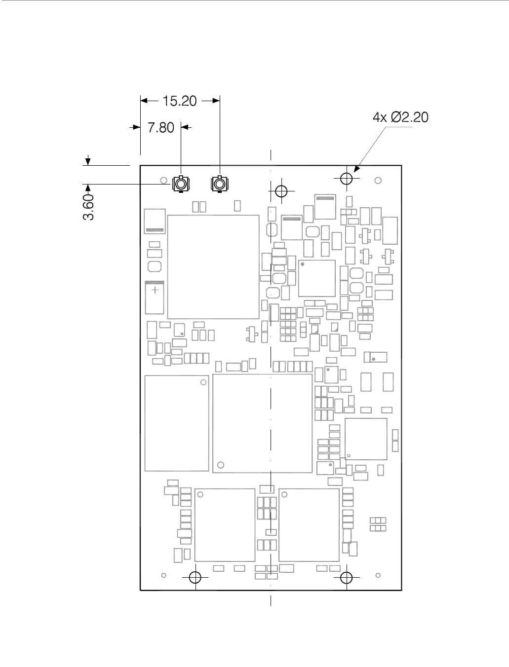
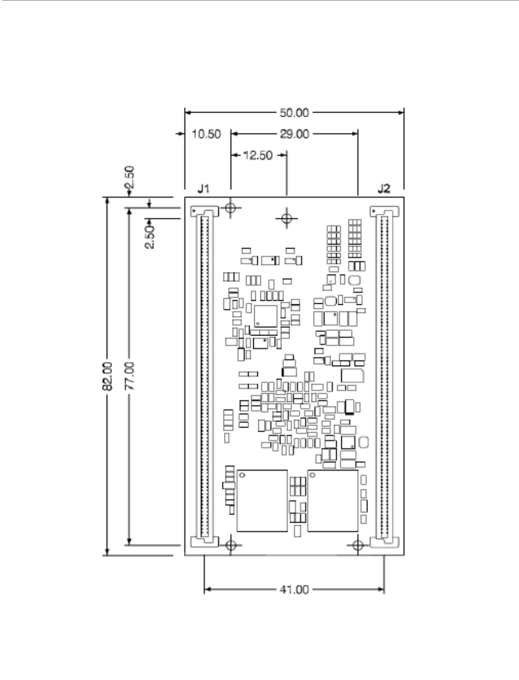
Module Dimensions
APPENDIX B
This appendix shows the dimensions of the ConnectCore for i.MX51 module, dimensions
are in millimeters.
ConnectCorefori.MX51
©2010DigiInternational,Inc. 141
Top View
ConnectCorefori.MX51
©2010DigiInternational,Inc. 142
Bottom View
ConnectCorefori.MX51
©2010DigiInternational,Inc. 143
Side View
Connectors
The ConnectCore for i.MX51 module uses two Berg/FCI connectors. The following table shows
the reference number of the connectors used in the module and the reference number of the
connectors used in the development board. The mated height of the module and the
development board is 5mm.
Device Berg/FCI Connector
ConnectCore for i.MX51 module 61082-181409LF
ConnectCore for i.MX51 development board 61083-184409LF
©2010DigiInternational,Inc. 144
Certifications
APPENDIX C
The ConnectCore for i.MX51 product complies with the following standards.
FCC Part 15 Class B
Radio Frequency Interface (RFI) (FCC 15.105)
The ConnectCore for i.MX51 module has been tested and found to comply with the limits for
Class B digital devices pursuant to Part 15 Subpart B, of the FCC rules. These limits are
designed to provide reasonable protection against harmful interference in a residential
environment. This equipment generates, uses, and can radiate radio frequency energy, and
if not installed and used in accordance with the instruction manual, may cause harmful
interference to radio communications. However, there is no guarantee that interference
will not occur in a particular installation. If this equipment does cause harmful interference
to radio or television reception, which can be determined by turning the equipment off and
on, the user is encouraged to try and correct the interference by one or more of the
following measures:
Reorient or relocate the receiving antenna.
Increase the separation between the equipment and receiver.
Connect the equipment into an outlet on a circuit different from that to which the
receiver is connected.
Consult the dealer or an experienced radio/TV technician for help.
Labeling Requirements (FCC 15.19)
This device complies with Part 15 of FCC rules. Operation is subject to the following two
conditions: (1) this device may not cause harmful interference, and (2) this device must
accept any interference received, including interference that may cause undesired
operation.
If the FCC ID is not visible when installed inside another device, then the outside of the
device into which the module is installed must also display a label referring to the enclosed

ConnectCoreWi‐i.MX51
©2010DigiInternational,Inc.. 145
module FCC ID. THis exterior label can use wording such as the following: “Contains
Transmitter Module FCC ID: MCQ-50M1699/ IC: 1846A-50M1699”.
RF Exposure
RF Exposure considerations require that a 20 cm separation distance between users and the
installed antenna location shall be maintained at all times when the module is energized.
OEM installers must consider suitable module and antenna installation locations in order to
assure this in 20cm separation, and end users be also be advised to the requirement.
Modifications (FCC 15.21)
Changes or modifications to this equipment not expressly approved by Digi may void the
user’s authority to operate this equipment.
Industry Canada
This digital apparatus does not exceed the Class B limits for radio noise emissions from digital
apparatus set out in the Radio Interference Regulations of the Canadian Department of
Communications.
Le present appareil numerique n’emet pas de bruits radioelectriques depassant les limites
applicables aux appareils numeriques de la class B prescrites dans le Reglement sur le
brouillage radioelectrique edicte par le ministere des Communications du Canada.
The maximum antenna gain permitted in the bands 5250-5350 MHz and 5470-5725 MHz to
comply with the e.i.r.p limit is, according to RSS-210 section A9.2(2)
250mW conducted power
1.0W max EIRP
This limit is met with the highest gain antenna listed, antennafactor ANT-DB1-RAF-RPS.
The maximum antenna gain permitted in the band 5725-5825 MHz to comply with the e.i.r.p
limit specified for non point-to-point operation is, according to RSS-210 section A9.2(3):
1W conducted power
4.0W max EIRP
This limit is met with the highest gain antenna listed,antennafactor ANT-DB1-RAF-RPS.
OEM installers and users are cautioned to take note that high-power radars are allocated as
primary users (meaning they have priority) of the bands 5250-5330 MHz and 5650-5850 MHz
and these radars could cause interference and /or damage to devices operating in these
frequency bands.

ConnectCoreWi‐i.MX51
©2010DigiInternational,Inc.. 146
Indoor/Outdoor
When the ConnectCore for i.MX51 module is installed in devices that can be used outdoors,
the channels in the band 5150-5250 MHz must be disabled to comply with US and Canadian
regulatory requirements. The OEM users are encouraged to inform end users of this
restriction as well.
Declaration of Conformity
(In accordance with FCC Dockets 96-208 and 95-19)
Digi International declares that the product:
to which this declaration relates, meets the requirements specified by the Federal
Communications Commission as detailed in the following specifications:
Part 15, Subpart B, for Class B equipment
FCC Docket 96-208 as it applies to Class B personal
Personal computers and peripherals
The product listed above has been tested at an External Test Laboratory certified per FCC
rules and has been found to meet the FCC, Part 15, Class B, Emission Limits. Documentation
is on file and available from the Digi International Homologation Department.
Manufacturer’s Name: Digi International
Corporate Headquarters: 11001 Bren Road East
Minnetonka MN 55343
Manufacturing Headquarters: 10000 West 76th Street
Eden Prairie MN 55344
Product Name ConnectCore for i.MX51
Model Number: 50001699-xx

ConnectCoreWi‐i.MX51
©2010DigiInternational,Inc.. 147
International EMC Standards
The ConnectCore for i.MX51 meets the following standards:
Standards ConnectCore for i.MX51
Emissions FCC Part 15 Subpart B
IS-003
Immunity EN 55022
EN 55024
Safety UL 60950-1
CSA C22.2, No. 60950-1
EN 60950-1
©2010DigiInternational,Inc. 148
Change Log
APPENDIX D
The following changes were made to this document in the revisions listed below.
Revision A
Initial release.
Revision B
Updated mechanical drawings (additional mounting holes, increased height of WLAN
variant).
Revision C
Updated document structure.
Updated "About the module" chapter.
Updated "About the Development board" chapter.
Updated "module specifications" appendix.
Updated mechanical drawings.
Revision D
Updated module pinout tables.
Updated “power” section.
Updated GPIO table.
Updated development board figures.
Updated “Switches and push-buttons,” “Jumper,” and “LEDs” sections.
Updated development board interfaces.
Updated several sub-sections to Appendix A.
Added electrical characteristics.
Updated the figures in Appendix B.

ConnectCoreWi‐i.MX51
©2010DigiInternational,Inc.. 149
Renamed “Appendix C: Change Log” to “Appendix D: Change Log.”
Added Appendix C: Certifications.
Added the Cable Specification: U.FL/W.FL to Chapter 2.
Added the Antenna specifications: 802.11 a/b/g antenna and Antenna specifications:
802.11 b/g antenna sections to Appendix A.
Added several sub-sections to the WLAN section of Appendix A.