Digi 50M1699 WLAN Module User Manual CC Wi i MX51 HRM
Digi International Inc WLAN Module CC Wi i MX51 HRM
Digi >
Contents
- 1. User Manual Part1
- 2. User Manual Part2
- 3. User Manual Part3
- 4. User Manual Part4
- 5. User Manual
User Manual Part2
ConnectCorefori.MX51
©2010DigiInternational,Inc. 71
Two 2 x 10 pin headers, X15 and X17, are provided on the development board for connecting
two Digi camera application kits (optional) or customer specific hardware.
X15 connector for camera 1
X17 connector for camera 2
X15 Pinout
X17 Pinout
Pin Signal Pin Signal
1+2.775V 2GND
3CSI1_D12 4CSI1_D13
5CSI1_D14 6CSI1_D15
7CSI1_D16 8CSI1_D17
9CSI1_D18 10 CSI1_D19
11 CSI1_MCLK 12 CSI1_PIXCLK
13 CSI1_HSYNC/GPIO3_15 14 CSI1_VSYNC/GPIO3_14
15 GPIO1_2/I2C2_SCL 16 GPIO1_3/I2C2_SDA
17 CSI1_D10 18 CAMRESET1#/GPIO3_13/CSI1_D19
19 GND 20 CSI1_D11
Pin Signal Pin Signal
1+2.775V 2GND
3CSI2_D12/GPIO4_9 4CSI2_D13/GPIO4_10
5CSI2_D14 6CSI2_D15
7CSI2_D16 8CSI2_D17
9CSI2_D18/GPIO4_11 10 CSI2_D19/GPIO4_12
11 CSI1_MCLK 12 CSI2_PIXCLK/GPIO4_15
13 CSI2_HSYNC/GPIO4_14 14 CSI2_VSYNC/GPIO4_13
15 GPIO1_2/I2SC2_SCL 16 GPIO1_3/I2C2_SDA
17 -18 CAMRESET2#/APIO3_7
19 GND 20 -
ConnectCorefori.MX51
©2010DigiInternational,Inc. 72
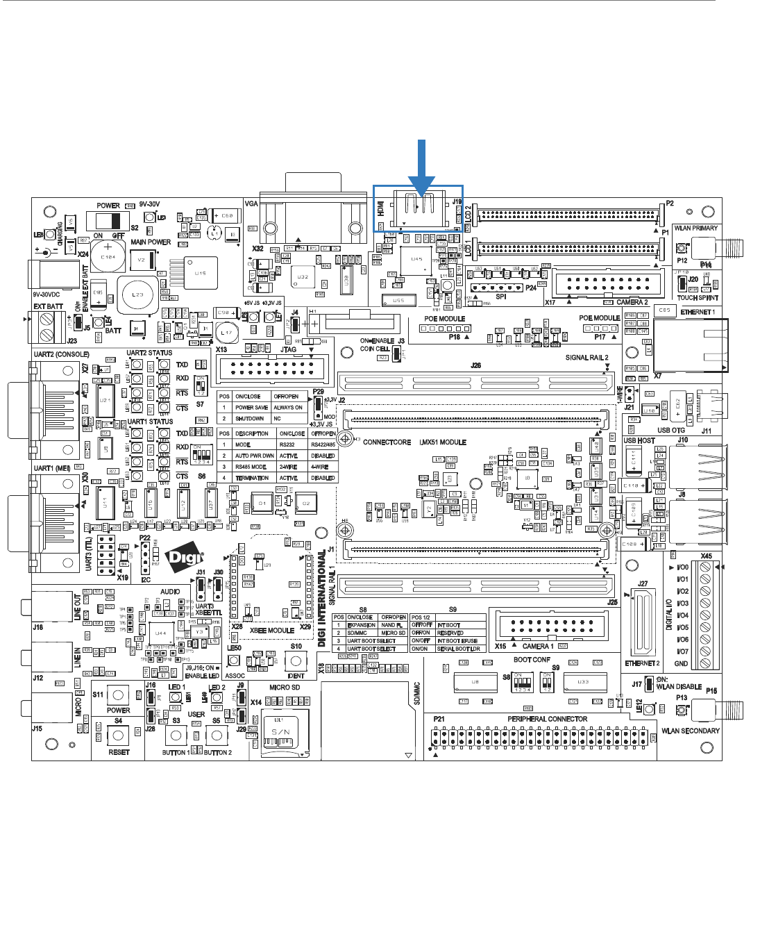
Digital IO Interface
Digital I/O
Connector, X45

ConnectCorefori.MX51
©2010DigiInternational,Inc. 73
Digital I/O Connector, X45
The development board provides a 3.81mm green terminal block, X45, for accessing eight on
chip digital GPIOs of the i.MX51 CPU.
On the development board, GPIO3_6 is connected to USER_KEY1. When using this signal as
digital I/O, the USER_KEY1 should not be used.
Note:
The digital I/O interface is not protected against ESD, over voltage or inverse polarity.
Care must be taken when using these signals.
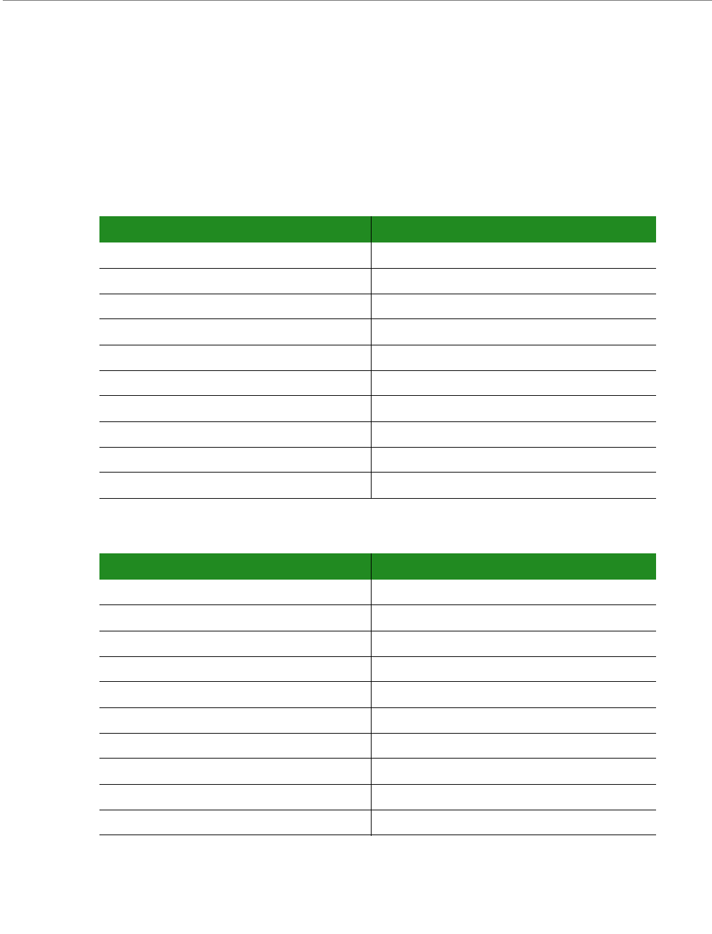
Pin Signal Voltage Level
1 GPIO3_11/SPI2_MISO/NANDF_RB3 +3.15V
2 GPIO3_18/NANDF_CS2# +3.15V
3 GPIO3_9/SPI2_RDY/USER_LED2/NANDF_RB1 +3.15V
4 GPIO3_10/SPI2_SCLK/USER_LED1/NANDF_RB2 +3.15V
5 GPIO3_20/NANDF_CS4# +3.15V
6 GPIO3_21/NANDF_CS5# +3.15V
7 GPIO3_22/NANDF_CS6# +3.15V
8 GPIO3_6/DISPB2_SER_DIO/USER_KEY1 +2.775
9GND 0V
ConnectCorefori.MX51
©2010DigiInternational,Inc. 74
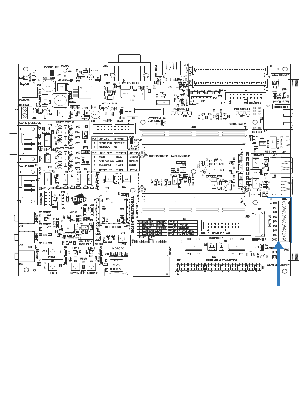
Ethernet 1 Interface
The development board provides one 8-wire RJ-45 jack with integrated 1:1 transformers and
link/activity LEDs for the Ethernet 1 interface. This interface is attached to the Fast Ethernet
controller (FEC) of the i.MX51. The ConnectCore for i.MX51 module provides a 10/100
Ethernet PHY chip for this interface.
The Ethernet 1 RJ-45 connector also supports 802.3af (PoE).
Ethernet 1
RJ-45,
X7

ConnectCorefori.MX51
©2010DigiInternational,Inc. 75
Ethernet 1, RJ-45 Connector X7
The table below shows the pinout of the Ethernet 1 RJ-45 connector.
The table below shows the description of the Ethernet 1 LEDs.
Pin Signal 802.3af End-Span
(mode A) 802.3ad Mid-Span
(mode B) Description
1 TXD+ Negative VPort Transmit data+
2 TXD- Negative VPort Trandmit data-
3 RXD+ Positive VPort Receive data+
4 EPWR+ Positive VPort Power from switch+
5 EPWR+ Positive VPort Power from switch+
6 RXD- Positive VPort Receive data-
7EPWR- Negative V
Port Power from switch-
8EPWR- Negative V
portP Power from switch-
LED Description
Yellow Network activity (speed):
- Flashing - indicates network traffic
- Off - no network traffic
Green Network link:
- On - indicates an active network link
- Off - no network link present
ConnectCorefori.MX51
©2010DigiInternational,Inc. 76
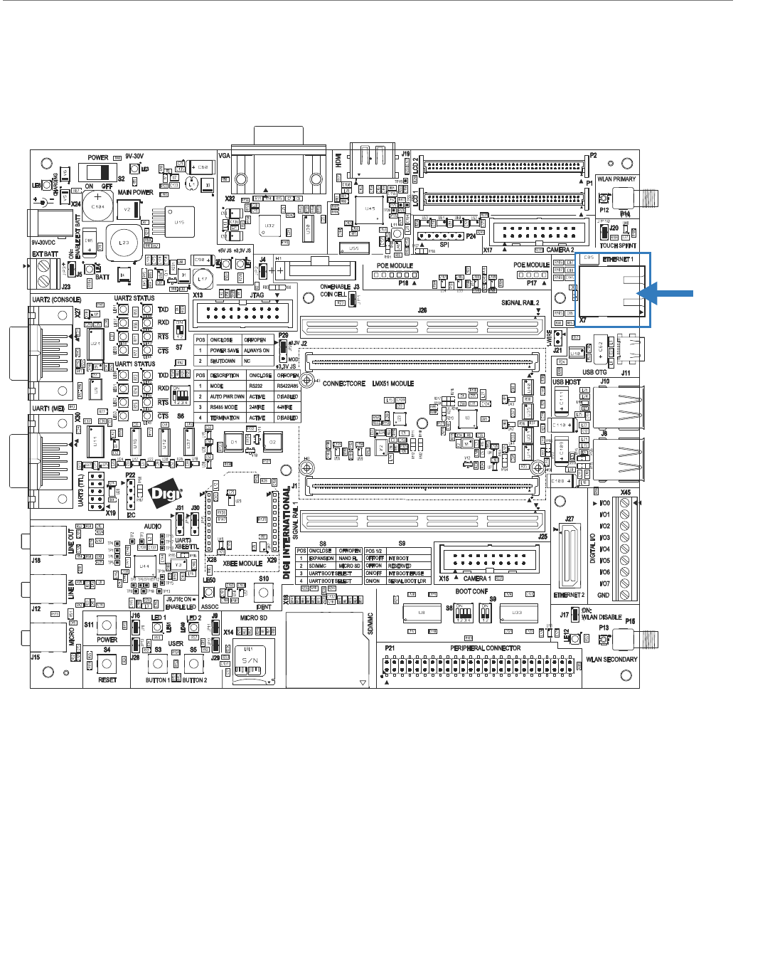
Ethernet 2 Interface
The development board provides a 2x20 expansion connector for connecting an optional Digi
Ethernet adapter board (100M_ETHADPT) or customer specific setup. The Ethernet 2
interface is provided by an optional on-module Ethernet MAC/PHY.
Note:
The ConnectCore for i.MX51 modules included in the development kits are supporting
the Ethernet 2 interface.
Ethernet 2
Connector, J27
ConnectCorefori.MX51
©2010DigiInternational,Inc. 77
Ethernet 2, Connector J17
The table below shows the pinout of the Ethernet 2 expansion connector.
Pin Signal Pin Signal
1 GND 2 GND
3 ETH2_TX+ 4 ETH2_RX+
5 ETH2_TX- 6 ETH2_RX-
7 GND 8 GND
9 Reserved (ETH2_DC+) 10 Reserved (ETH2_DD+)
11 Reserved (ETH2_DC-) 12 Reserved (ETH2_DD-)
13 GND 14 GND
15 ETH2_ACTIVITY# 16 ETH2_LINK#
17 - 18 -
19 - 20 -
21 - 22 -
23 - 24 -
25 - 26 -
27 - 28 -
29 - 30 -
31 - 32 -
33 - 34 -
35 - 36 -
37 - 38 -
39 - 40 -
ConnectCorefori.MX51
©2010DigiInternational,Inc. 78
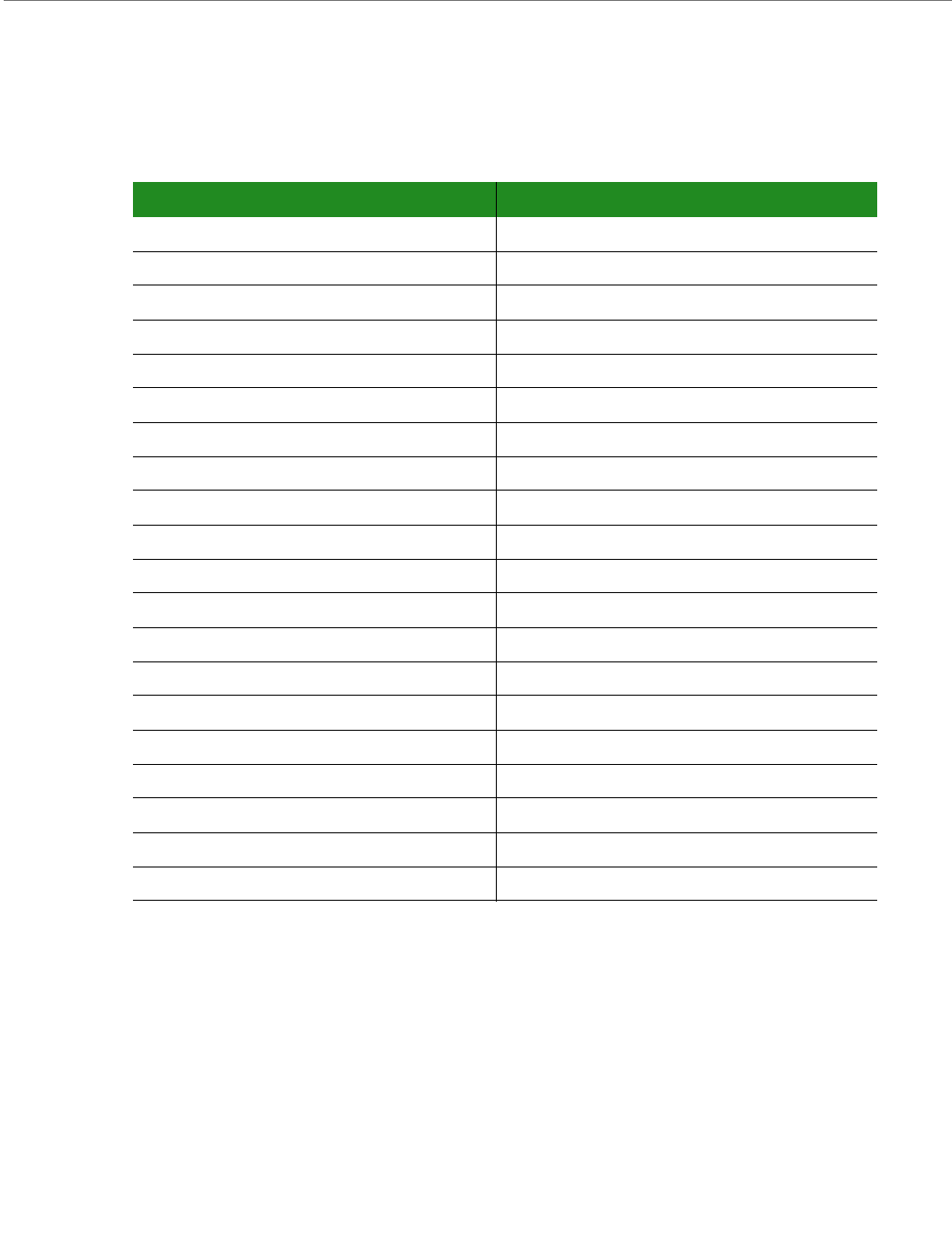
HDMI Interface
The development board provides an HDMI interface connected to the disaply interface 1 of
the ConnectCore for 1.MX51 CPU. An Analog Devices AD9389 HDMI transmitter is used in the
development board. This HDMI transmitter is controlled through the I2C port 2 of the
ConnectCore for 1.MX51.
HDMI Connector, J19
ConnectCorefori.MX51
©2010DigiInternational,Inc. 79
The I2C device address of the HDMI transmitter is the following:
HDMI Connector, J19
The development board provides an HDMI connector, J19. THe HDMI interface is connected to
the Display 1 interface of the ConnectCore for 1.MX51 CPU.
The table below shows the pinout of the HDMI connector:
Interface I2C Address (7 bits)
HDMI transmitter (AD9389)2 0 x 39
Pin Signal
1HDMI_TX2+
2GND
3HDMI_TX2-
4HDMI_TX1+
5GND
6HDMI_TX1-
7HDMI_TX0+
8GND
9HDMI_TX0-
10 HDMI_TXC+
11 GND
12 HDMI_TXC-
13 NC
14 NC
15 HDMI_SCL
16 HDMI_SDA
17 GND
18 +5V
19 HOTPLUG_DET
ConnectCorefori.MX51
©2010DigiInternational,Inc. 80
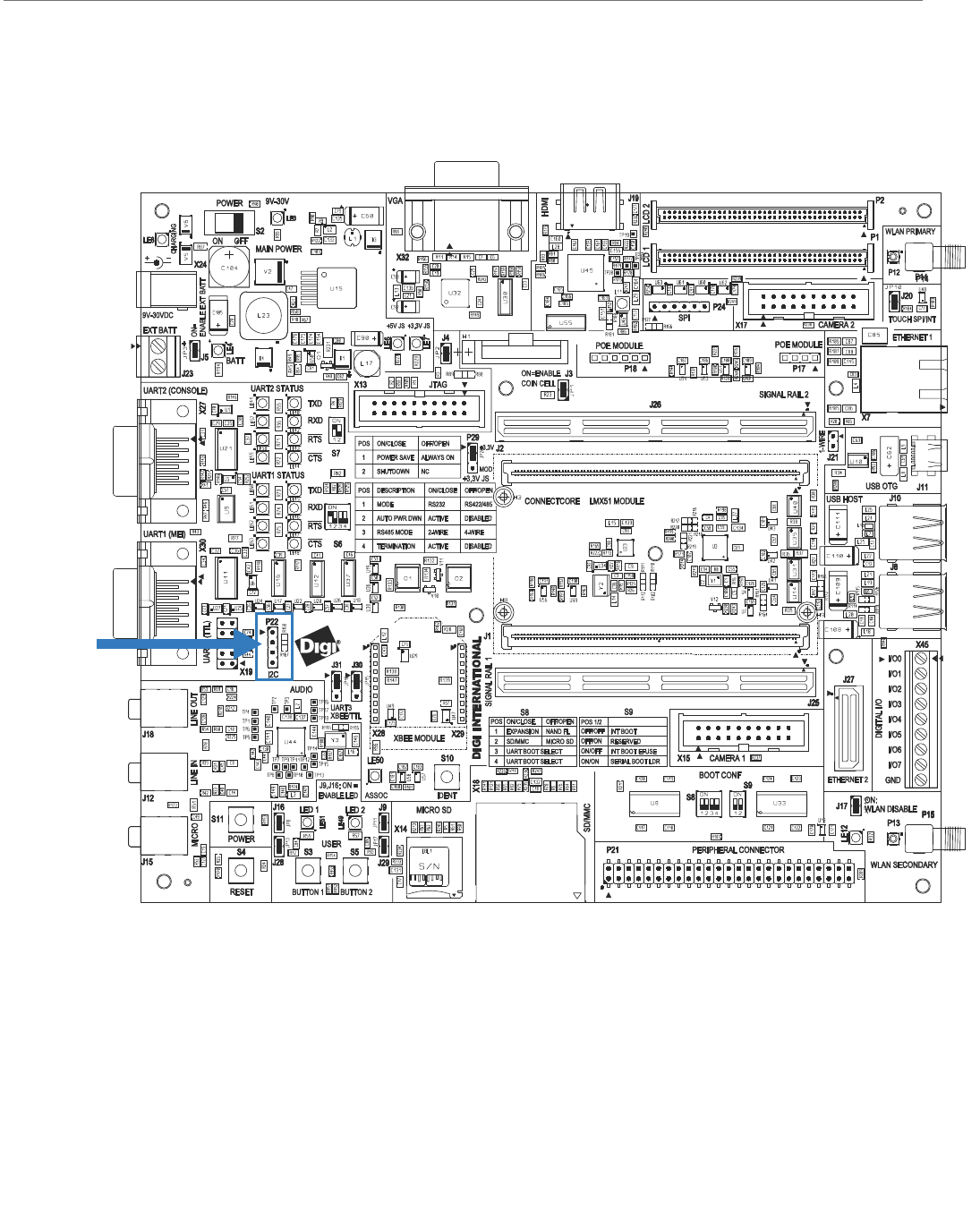
I2C Interface
I C Header,
P22
2
ConnectCorefori.MX51
©2010DigiInternational,Inc. 81
2C Header, P22
Pin header P22 provides access to the i.MX51 I2C port 2 interface.
The I2C port 2 is connected to the following headers/interfaces on the development board.
I2C port 2 is connected to the following interfaces of the ConnectCore for 1.MX51 module:
The table below provides the pinout of connector P22:
By default, this interface is configuresto operate in GPIO mode.
Interface I2C Address (7 bits)
I2C Header -
Camera 1 0 x5 C (Digi CC-ACC-MT9V111)
Camera 2 0 x4 8 (Digi CC-ACC-MT9V111)
HDMI Transmitter 0 x 39
LCD 1 -
LCD 2 -
Audio CODEC 0 x 1A
Peripheral connector -
Interface I2C Address (7 bits)
Accelerometer (MMA7455L) 0 x 31D
Pin Function Defaults to
1I
2C_SDA GPIO1_3
2 +2.775V
3I
2_SCL GPIO1_2
4GND
ConnectCorefori.MX51
©2010DigiInternational,Inc. 82
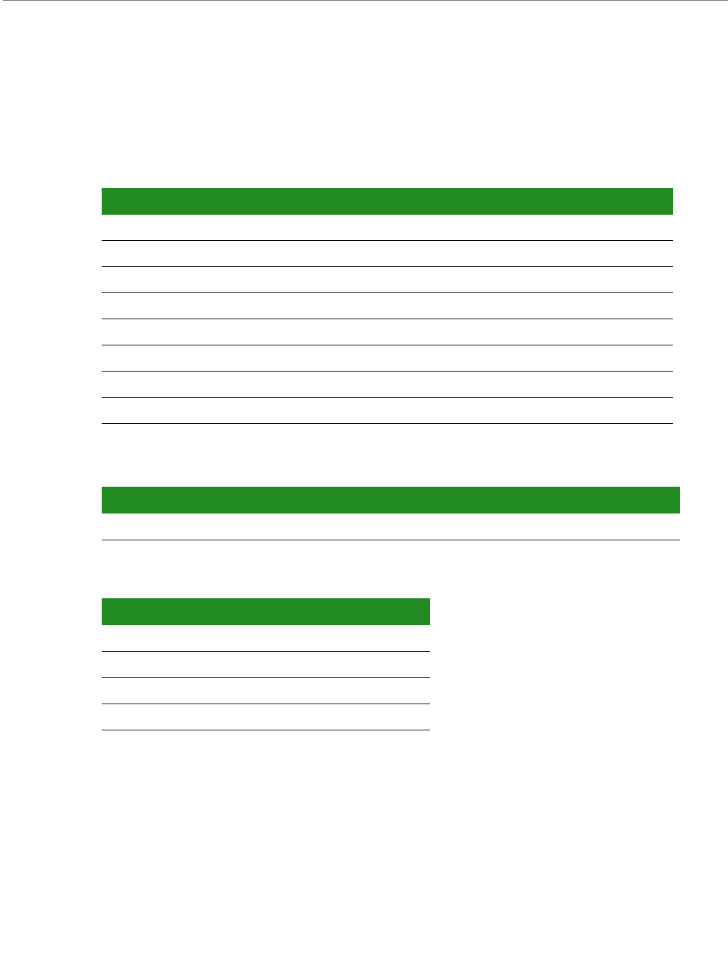
JTAG Interface
JTAG Interface, X13
ConnectCorefori.MX51
©2010DigiInternational,Inc. 83
Standard JTAG ARM Connector, X13
The standard JTAG ARM connector is a 20-pin header and can be used to connect
development tools (ICS) such as Ronetix PEEDI or other.
Note:
In order to enable ETM functionality, Digi offers an optional ETM adapter board (sold
separately, Digi P/N CC-ACC-MX51-ETM). Please contact us.
Pin Function Pin Function
1 +1.8V 2 +3.3V
3 JTAG_TRST# 4 GND
5 JTAG_TDI 6 GND
7 JTAG_TMS 8 GND
9 JTAG_TCK 10 GND
11 Reserved (RTCK) 12 GND
13 JTAG_TDO 14 GND
15 JTAG_RESET# 16 GND
17 JTAG_DE# 18 GND
19 GND 20 GND
ConnectCorefori.MX51
©2010DigiInternational,Inc. 84
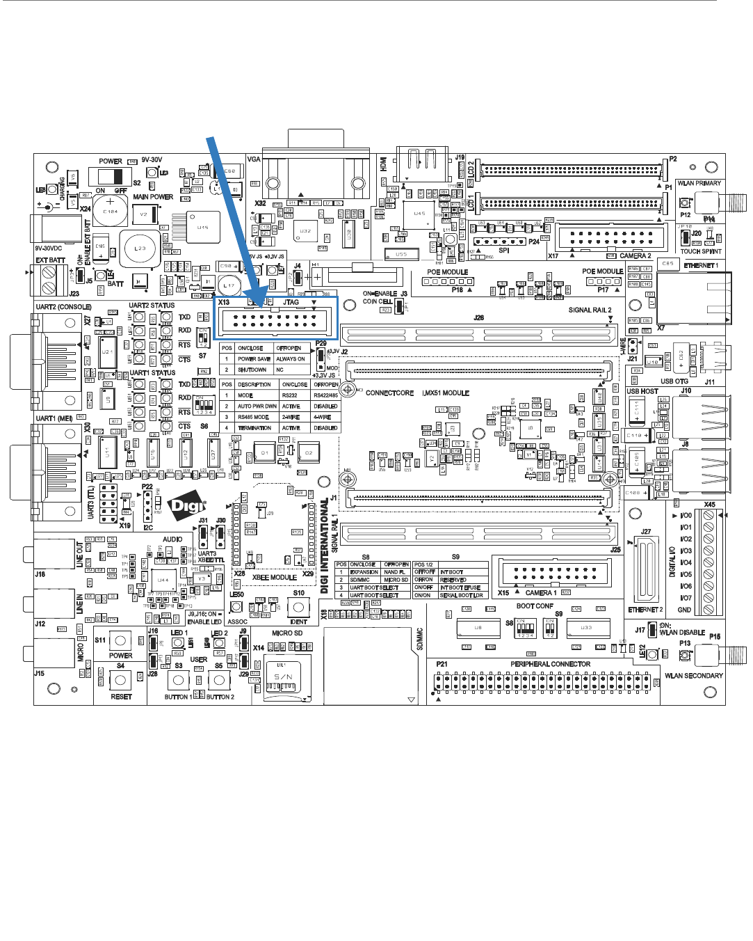
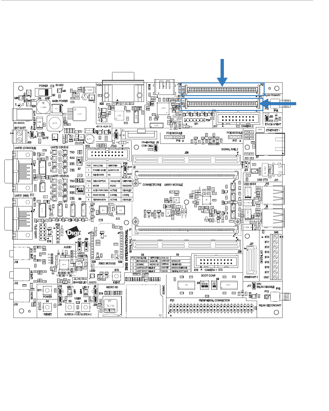
LCD Interfaces
The development board provides two 2x40 pin, 1.27mm connectors for accessing a Digi-
provided LCD application boards (CC-ACC0LCDW-70) or a user defined LCD application board.
P1 : corresponds to i.MX51 display interface 1
P2 : corresponds to i.MX51 display interface 2
LCD2 Connector, P2
LCD1
Connector, P1

ConnectCorefori.MX51
©2010DigiInternational,Inc. 85
LCD 1 Connector, P1
This connector provides access to the following capabilities:
18-bit (RGB x 8bit) LCD
SPI bus for a touch screen controller
Touch screen (on-module, shared with LCD2)
Interrupt input for touch screen
I2C bus
2 x GPIO
+3.3VDC supply and a 9-30VDC supply
P1 Pinout
The table below shows the pinout of the LCD1 connector, P1:
Pin Function Pin Function
1 LCD1_DATA16 (R0) 2 LCD1_DATA17 (R1)
3 LCD1_DATA12 (R2) 4 LCD1_DATA13 (R3)
5 LCD1_DATA14 (R4) 6 LCD1_DATA215(R5)
7 LCD1_DATA16 (R6) 8 LCD1_DATA17 (R7)
9- 10-
11 - 12 -
13 GND 14 GND
15 LCD1_DATA10 (G0) 16 LCD1_DATA11 (G1)
17 LCD1_DATA6 (G2) 18 LCD1_DATA7 (G3)
19 LCD1_DATA8 (G4) 20 LCD1_DATA9 (G5)
21 LCD1_DATA10 (G6) 22 LCD1_DATA11 (G7)
23 - 24 -
25 - 26 -
27 GND 28 GND
29 LCD1_DATA4 (B0) 30 LCD1_DATA5 (B1)
31 LCD1_DATA0 (B2) 32 LCD1_DATA1 (B3)
33 LCD1_DATA2 (B4) 34 LCD1_DATA3 (B5)
35 LCD1_DATA4 (B6) 36 LCD1_DATA75(B7)
37 - 38 -
ConnectCorefori.MX51
©2010DigiInternational,Inc. 86
39 - 40 -
41 GND 42 GND
43 LCD1_BIAS 44 LCD1_PCLK
45 LCD1_PWREN# 46 GND
47 LCD1_VSYNC 48 LCD1_HSYNC
49 - 50 -
51 - 52 -
53 - 54 -
55 GND 56 GND
57 TOUCH_X1 58 TOUCH_Y1
59 TOUCH_X2 60 TOUCH_Y2
61 I2C2_SDA 62 I2C2_SCL
63 LCD_SPI_SS# 64 SPI1_CLK
65 SPI1_MOSI 66 SPI1_MISO
67 RESET# 68 LCD1_TOUCH_INT/EXT#
69 LCD1_GPIO1 70 LCD1_GPIO2
71 LCD_PENIRQ 72 GND
73 +3.3V 74 +3.3V
75 +9-30V 76 +9-30V
77 +9-30V 78 +9-30V
79 - 80 -
Pin Function Pin Function
ConnectCorefori.MX51
©2010DigiInternational,Inc. 87
LCD 2 Connector, P2
This connector provides access to the following capabilities:
18-bit (RGB x 8bit) LCD
SPI bus for a touch screen controller
Touch screen (on-module, shared with LCD1)
Interrupt input for touch screen
I2C bus
2 x GPIO
+3.3VDC supply and a 9-30VDC supply
P2 Pinout
The table below shows the pinout of the LCD2 connector, P2:
Pin Function Pin Function
1 LCD2_DATA16 (R0) 2 LCD2_DATA17 (R1)
3 LCD2_DATA12 (R2) 4 LCD2_DATA13 (R3)
5 LCD2_DATA14 (R4) 6 LCD2_DATA15 (R5)
7 LCD2_DATA16 (R6) 8 LCD2_DATA17 (R7)
9- 10-
11 - 12 -
13 GND 14 GND
15 LCD2_DATA10 (G0) 16 LCD2_DATA11 (G1)
17 LCD2_DATA6 (G2) 18 LCD2_DATA7 (G3)
19 LCD2_DATA8 (G4) 20 LCD2_DATA9 (G5)
21 LCD2_DATA10 (G6) 22 LCD2_DATA11 (G7)
23 - 24 -
25 - 26 -
27 GND 28 GND
29 LCD2_DATA4 (B0) 30 LCD2_DATA5 (B1)
31 LCD2_DATA0 (B2) 32 LCD2_DATA1 (B3)
33 LCD2_DATA2 (B4) 34 LCD2_DATA3 (B5)
35 LCD2_DATA4 (B6) 36 LCD2_DATA5 (B7)
37 - 38 -

ConnectCorefori.MX51
©2010DigiInternational,Inc. 88
39 - 40 -
41 GND 42 GND
43 LCD2_BIAS 44 LCD2_PCLK
45 LCD2_PWREN# 46 GND
47 LCD2_VSYNC 48 LCD2_HSYNC
49 - 50 -
51 - 52 -
53 - 54 -
55 GND 56 GND
57 TOUCH_X1 58 TOUCH_Y1
59 TOUCH_X2 60 TOUCH_Y2
61 I2C2_SDA 62 I2C2_SCL
63 LCD_SPI_SS# 64 SPI1_CLK
65 SPI1_MOSI 66 SPI1_MISO
67 RESET# 68 LCD2_TOUCH_INT/EXT#
69 LCD2_GPIO1 70 LCD2_GPIO2
71 LCD_PENIRQ 72 GND
73 +3.3V 74 +3.3V
75 +9-30V 76 +9-30V
77 +9-30V 78 +9-30V
79 LED_BCK+ 80 LED_BCK-
Pin Function Pin Function
ConnectCorefori.MX51
©2010DigiInternational,Inc. 89
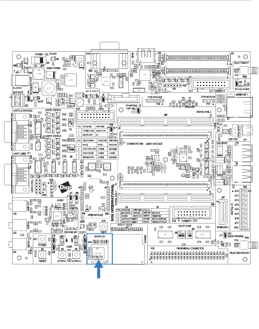
MicroSD™ Card Interface
MicroSD Connector, X14

ConnectCorefori.MX51
©2010DigiInternational,Inc. 90
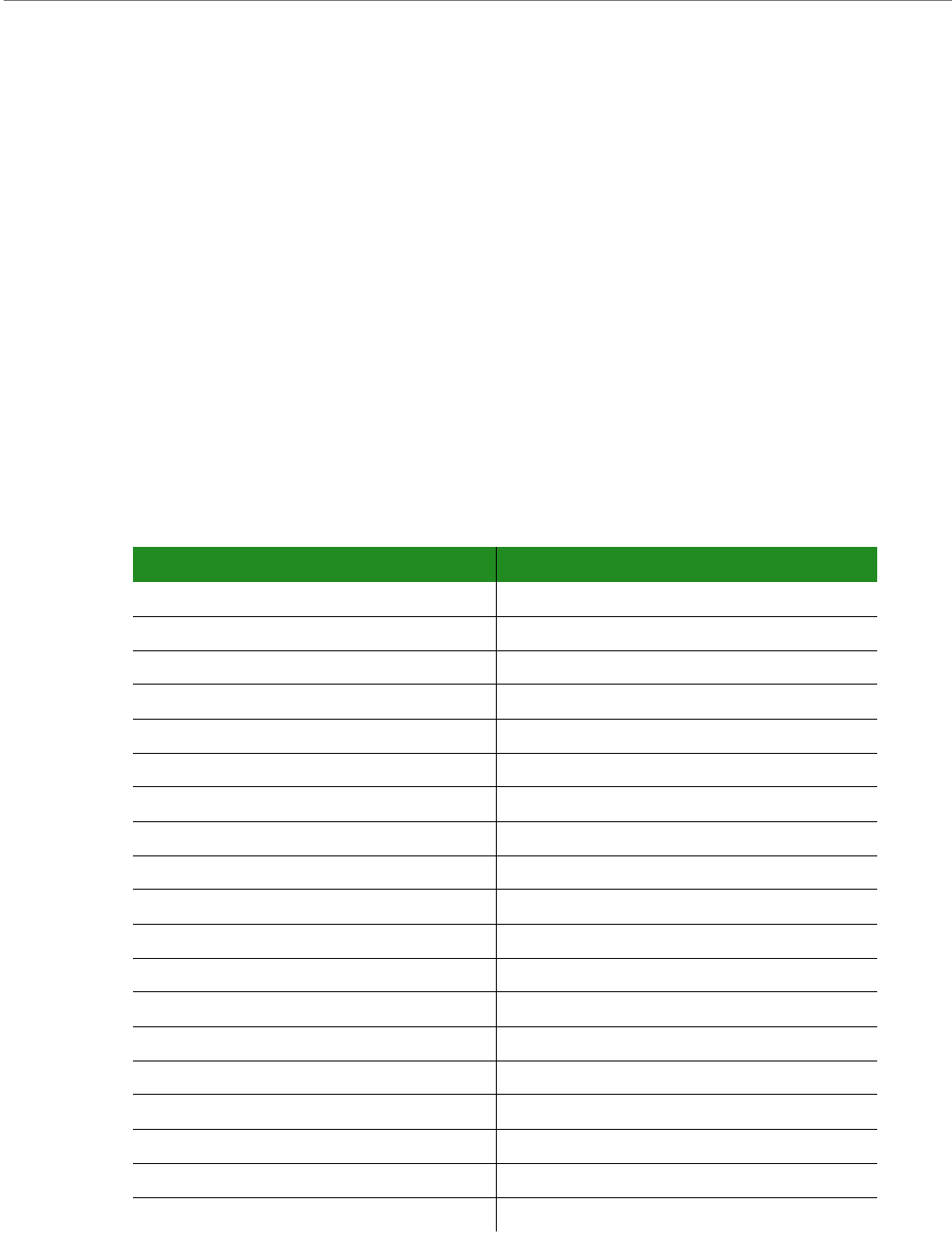
MicroSD™ Connector, X14
The development board provides one MicroSD™ card connector, X14. This interface is
connected to the enhanced Secured Digital Host controller 1 (eSDHC1) of the i.MX51 CPU.
The MicroSD™ connector used on the development board does not provide a card detect pin
(pin-9 and pin-10 are connected to chassis). A hot-plug insertion or removal is not possible
with this connector.
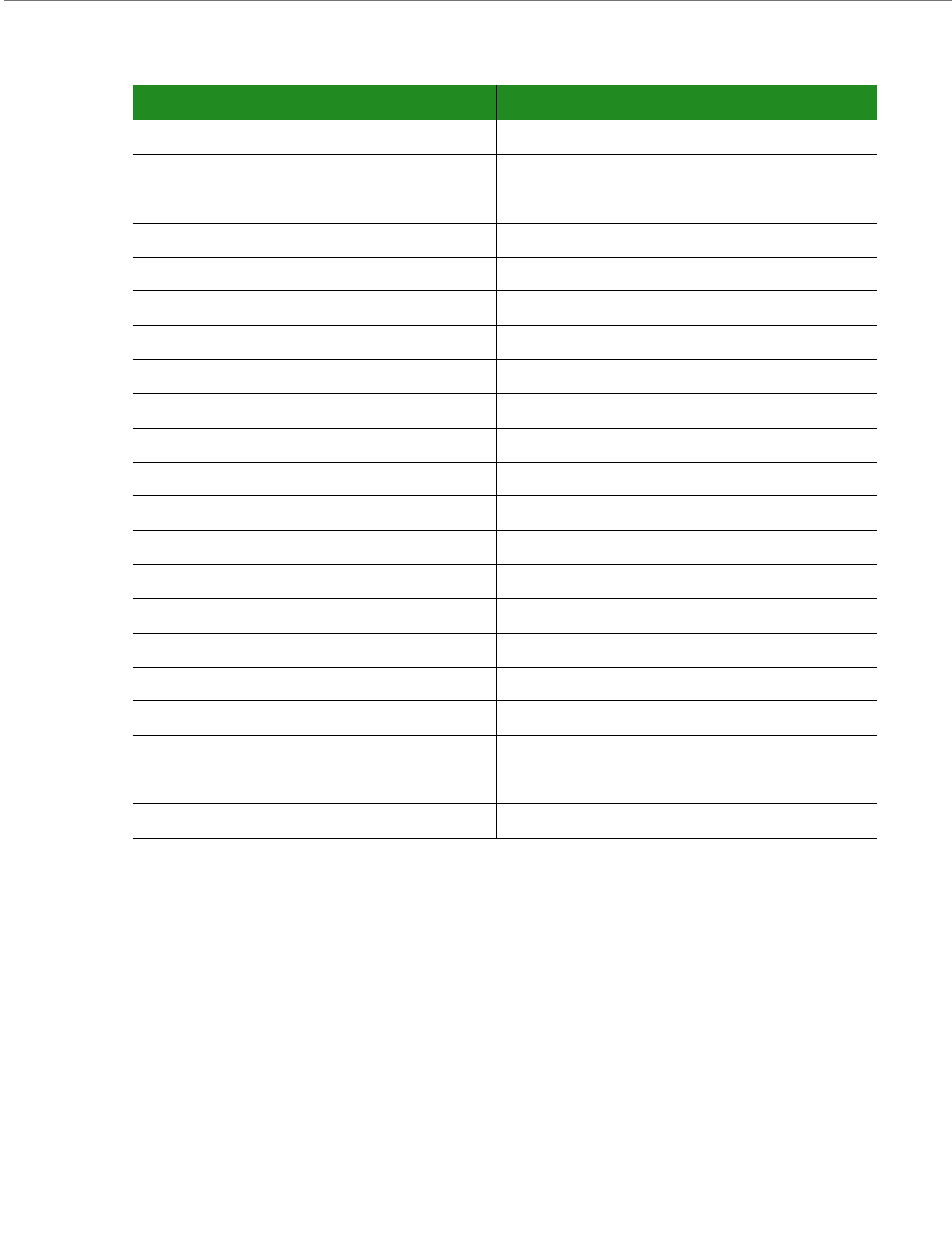
The following table shows the pinout of the MicroSD™ connector:
Pin Signal
1SD_SATA2
2 SD_DATA3
3SD_CMD
4+3.3V
5SD_CLK
6GND
7 SD_DATA0
8 SD_DATA1
9 SD_CD (Connected to chassis)
10 SD_CD (Connected to chassis)