Electronic Systems Technology ESTEEM192S Wireless Modem User Manual part 1
Electronic Systems Technology Wireless Modem part 1
Contents
user manual part 1

CHAPTER 1
STARTING OUT
BEFORE YOU START
ESTEEM UTILITY
Installing ESTeem Utility Software – Windows 95/98/NT
Running The Program
STARTING OUT
BASIC ESTEEM PROGRAMMING
HELP Functions
Saving A Program
Restoring Factory Defaults
CHAPTER 1
STARTING OUT
Revised: 11 Feb 99 1-2
BEFORE YOU START
Congratulations on your purchase of the ESTeem Wireless
Modem! This section of the manual will describe the basic
functioning and programming of the ESTeem to get your
wireless network up as soon as possible. It is recommended
that any first time user of the ESTeem and those that are
unfamiliar with its operation complete all steps in this
section before proceeding.
Take a few minutes to inventory your equipment before you
proceed. Report any missing or damaged items to
Customer Support as soon as possible. We at Electronic
Systems Technology, Inc. (EST) are constantly trying to
improve our products and support system so if you have any
comments or suggestions on improvement of this manual,
please contact us at (509) 735-9092.
The completion of this section requires loading the ESTeem
Utility program on your computer. The following section
will describe the installation and use of this valuable utility
program.
ESTEEM UTILITY
The ESTeem Utility is designed to assist the ESTeem user
in programming and troubleshooting. The Utility covers
basic operation, programming, PLC applications, and
diagnostics of the ESTeem. The ESTeem Utility Program
is designed to operate with Windows 95®, Windows 98®
and Windows NT®.
Installing ESTeem Utility Software
Windows 95/98/NT
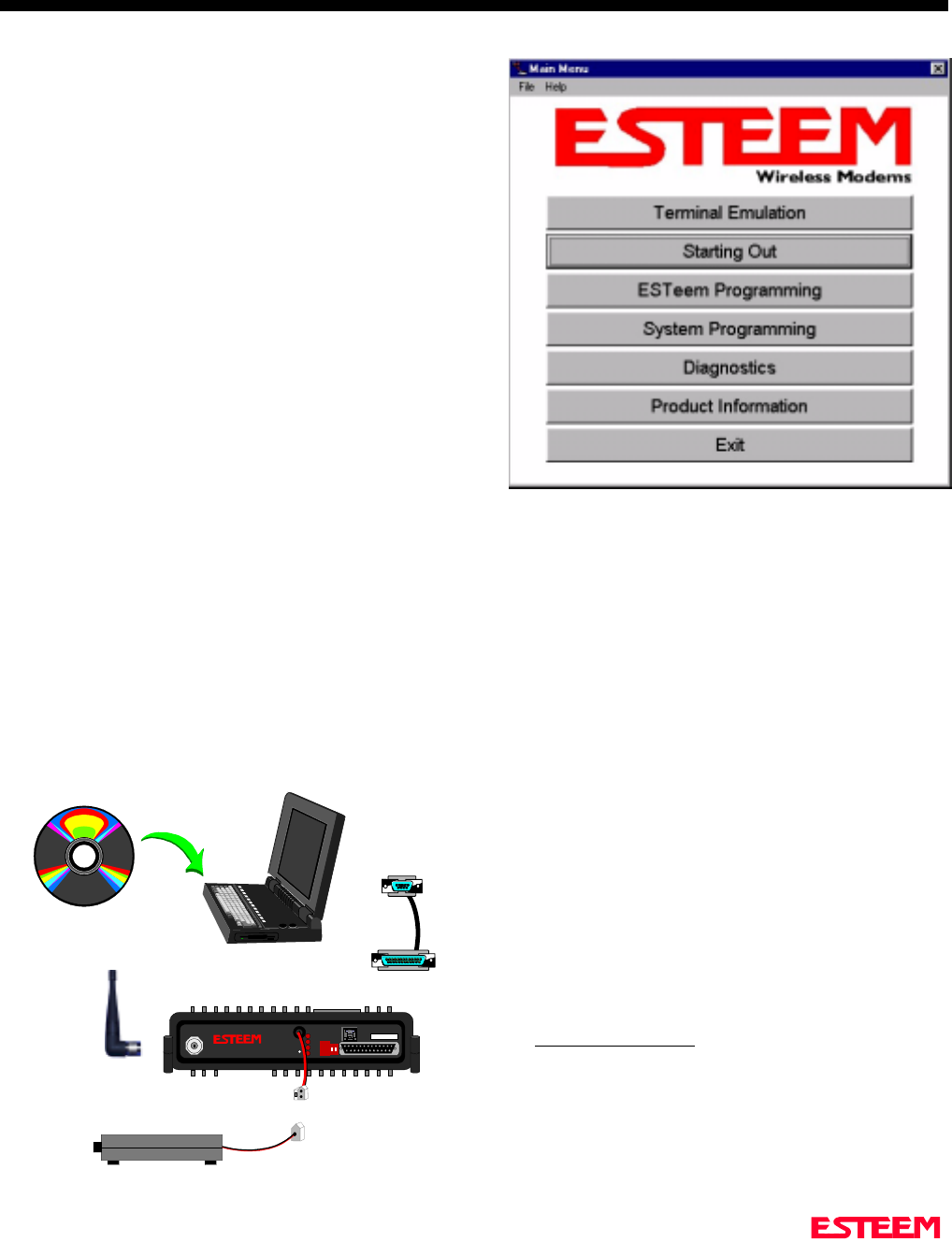
1. Place the ESTeem CD in your CD-ROM drive
(Figure 1).
2. Select Run on the Start Menu.
3. Type (your CD-ROM drive letter):\Utility\Setup.exe
4. Click the OK button and the program will begin
installation.
Running The Program
1. Select the ESTeem Utility Icon on Start>Programs
menu. Figure 2 shows an example of the Main Utility
Menu.
STARTING OUT
This section covers the basics setup and testing for the
ESTeem wireless modem. If this is your first experience
with the ESTeem wireless modems or you are unclear on
how to set the frequency, squelch, or test communication,
the ESTeem Starting Out section will guide you through
the basics of wireless communication.
Figure 2: ESTeem Utility Main Menu
RS-232C Interface Cable
(EST P/N AA061)
12 VDC Power Supply
(EST P/N AA174)
2 Pin Molex
Connector
ESTeem Model 192S
Rear View
ESTeem Model 192 Utility
Software Windows Version
Computer Running
Windows 95/98/NT
S/N:
T/E
TX
RX
PWR
IR
Port
Phone
Model 192S
Antenna
12 VDC
RESET
Rubber Duck Antenna
(EST P/N AA01S)
Figure 1: Installation Diagram
CHAPTER 1
STARTING OUT
Revised: 11 Feb 99 1-3
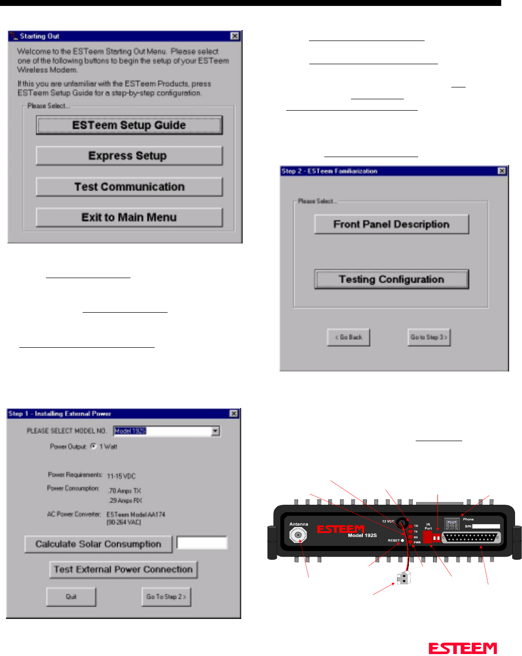
1. Select ESTeem Starting Out from the main menu. A
window like the one in Figure 3 will be displayed. If
this is your first time using the ESTeem wireless
modems, select ESTeem Setup Guide for a complete
description of all ESTeem functions. Proceed to step
2.
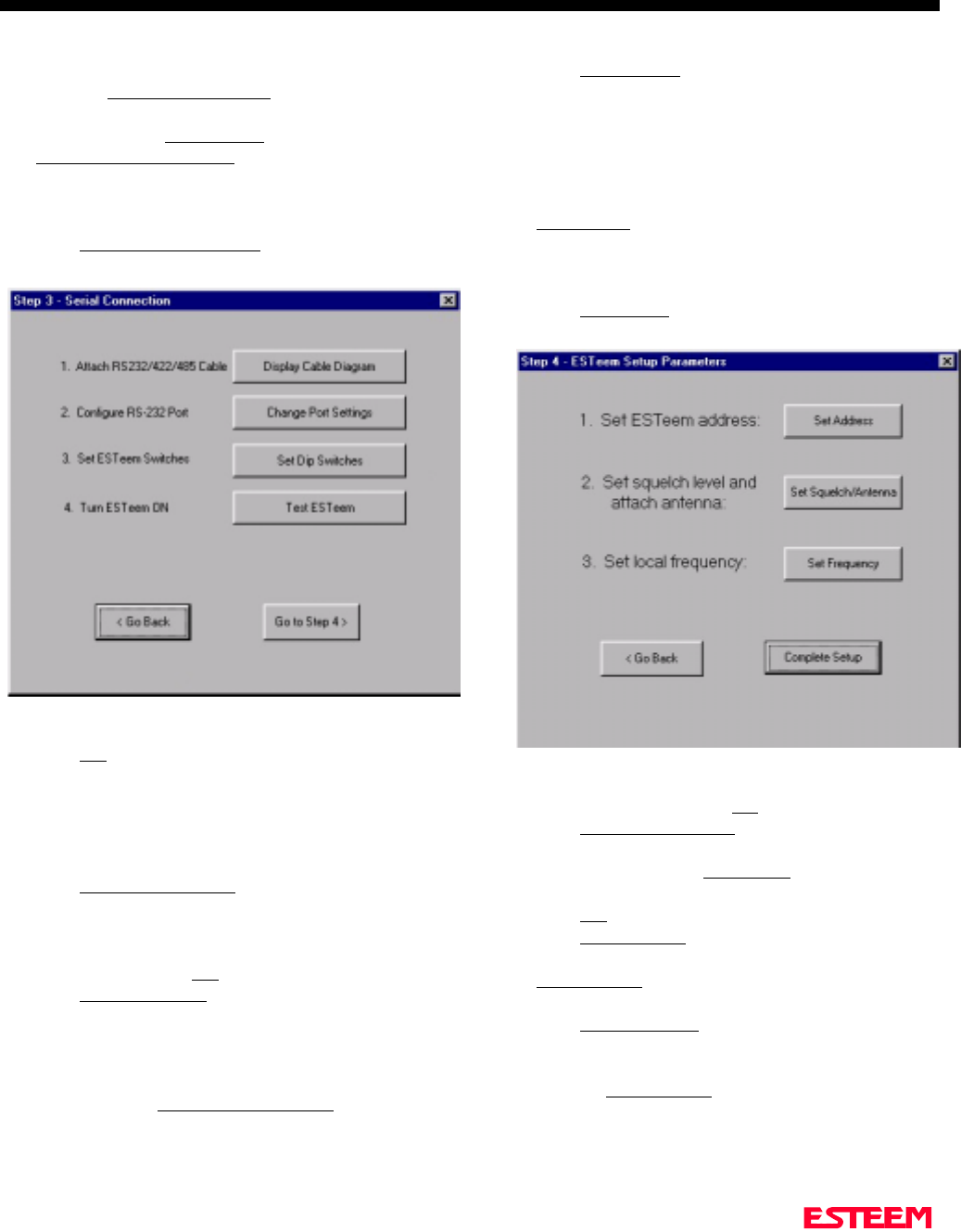
2. Step 1 – Installing External Power window will be
displayed (Figure 4). Select Model 192S on the
menu and the voltage and current specifications will
be displayed. The ESTeem model AA174 power
supply can be used with all ESTeem products. If you
are using the ESTeem in a solar power application,
press Calculate Solar Consumption button for the
Amp/Hours required.
3. Press Test External Power Connection button. If you
have connected your power cable correctly your
Power LED should be illuminated. Press OK to
continue. Press Go To Step 2 button to proceed.
4. Step 2 – ESTeem Familiarization window will be
displayed (Figure 5). This step will explain the
connections to ESTeem Model 192S front panel and
provide a setup diagram for testing.
5. Press the Front Panel Description button and a
window containing the ESTeem Model 192S front
panel will appear (Figure 6). Press any one of the
buttons for a complete description of the item’s
function. For example, press the Power LED button
and the description of the power LED and its use will
Figure 3: Starting Out Main Menu
Figure 4: Step 1 - Installing External Power
Figure 5: Step 2 – ESTeem Familiarization
Antenna Connector
(TNC-R)
12 VDC Input
Power Connector
(2 Pin Molex)
Reset Switch
RS-232, 422 and 485
Input/Output Connector
(25 Pin DB Connector)
Phone Modem
Interface
RS-232/422/485
Setup Switches
Power LED
IR Port
Transmit LED
Receive LED
T/E LED
•Link Connect/Disconnect
•Auto Connect Enable
•Serial Port Framing Error
Figure 6: ESTeem Front Panel
CHAPTER 1
STARTING OUT
Revised: 11 Feb 99 1-4
be displayed.
6. Press the Testing Configuration button and a window
containing the Testing Diagram (Figure 1) will be
displayed. Press Go To Step 3 button to proceed.
7. Step 3 – Serial Connection window will be displayed
(Figure 7). This step will help configure the
computer and the ESTeem to communicate with each
other.
8. Press Display Cable Diagrams button and all serial
pins to the ESTeem Model 192S will be displayed.
Press OK to continue.
Note: A standard 9-Pin serial port on a computer to
ESTeem interface cable is the ESTeem AA061
(Figure 1).
9. Press Change Port Settings. This window will
configure the communications port on your computer
to operate with the ESTeem modem. Select the
operating parameters you wish or set to the default of
19,200,N,8,1. Click OK to continue.
10. Press Set Dip Switches button. This window will
configure the ESTeem’s RS-232/422/485 to operate
at the setting selected in step 8. Turn both Switches 1
and 2 on the RS-232 setup switches (Figure 6) to the
OFF/Down position and press the Reset Button on the
ESTeem. Press Download Port Settings button to
return to the Step 3 menu. Return Switch 1 on the
RS-232/422/485 port setup switches to the ON
position and press the reset button.
11. Press Test ESTeem button. If the ESTeem serial
interface cable and communication port are operating
correctly the ESTeem Welcome Message will be
displayed. This will confirm communication between
the computer and the ESTeem. If you do not receive
a welcome message, follow the on-screen
troubleshooting guide that will be displayed. Press
Go to Step 4 button to proceed.
12. Step 4 – ESTeem Setup Parameters window will be
displayed (Figure 8). This step will complete the
setup for your ESTeem Model 192S.
13. Press Set Address button. You must give each
ESTeem a unique address in the system. Type in the
address number and press OK to continue.
14. Press Set Squelch/Antenna button. This section will
give you instructions on antenna placement and
installation. Press the Set Squelch button and follow
the on-line guide to configure the ESTeem squelch.
Press OK to continue.
15. Press Set Frequency button. Select the center
frequency for your ESTeem Model 192S and press
Set Frequency to continue. Set all ESTeems to the
same frequency for operation within this section.
16. Press Complete Setup. You have just configured all
operating parameters within the ESTeem. If this is
your first ESTeem you have programmed for testing,
press the Express Setup button on the Setup Main
Menu (Figure 3) to program subsequent ESTeem
Modems. The Express Setup will allow you to
quickly configure the remaining ESTeem modems
without additional instruction. If you have at least
Figure 7: Step 3 – Serial Connection
Figure 8: Step 4 – ESTeem Setup Parameters

CHAPTER 1
STARTING OUT
Revised: 11 Feb 99 1-5
two ESTeems programmed and wish to test
communication, proceed to step 17.
17. Press Test Communication button. This section will
allow you to test the radio frequency (RF)
communications between two or more ESTeems.
Two types of tests are listed in this window (Figure
6). If you have a computer attached to both ESTeems
proceed to step 18 and if you only have one computer
to test both ESTeems proceed to step 19.
18. The first test will be used if you have a computer
attached to both ESTeems. Select the first of two
items and press ENTER. Follow the instructions on
the screen to establish a communication link between
modems.
19. This second test will allow you to use the remote
ESTeem as a digi-repeater for your local modem.
This procedure is explained in the window and can
test communication with only one computer.
20. You now have completed the basic programming and
setup of your ESTeem modems. You have tested
their operation with each other and are now ready to
proceed in programming them for your application.
Press Exit to Main Menu and continue with the
programming of the ESTeem for your application.
BASIC ESTEEM PROGRAMMING
Most of the ESTeem commands outlined in this section
have been automatically input to the modem by the
ESTeem Utility program. A few of the commands used
most often in troubleshooting and programming are
covered here. These commands can be programmed to
the modem directly by the Terminal Emulation section of
the utility or by any other terminal software package.
HELP Functions
The ESTeem has over a hundred software commands to
aid the user in their application. The HELP command
allow the user to list the various software commands and
their respective values.
From the COMMAND mode, type HELP<cr>. Your
display should list the following:
Help switches are:
ALL (Lists all settings).
CHANGE (List settings changed from factory default).
CONTROL (List settings dealing with control).
PLC (List settings for PLCs).
RADIO (List settings for ESTeem radio).
RS232 (List settings for RS-232/422/485)
SETUP (List settings for control).
SYSTEM (List settings for system).
These are the different software categories.
Example: HELP SETUP<cr> , will list all the
programmable variables and their settings for the SETUP
category.
You can interrogate a discrete software command by just
typing the command followed by a <cr>.
Example: ADD<cr> , will list the current address saved
in the connected ESTeem.
Note Appendix E of this manual will have the
complete listing of software commands and
categories for the factory default of the
ESTeem.
Saving A Program
A program is saved by typing in the SAVE command at
the CMD: prompt. The programming variables that have
been changed will be written to the non-volatile memory.
The programming parameters will be loaded each time the
modem is powered up or reset.
Restoring Factory Defaults
The ESTeem has a very simple procedure to restore the
program variables in the unit to the factory default setting.
When the FA<cr> command is entered from the
command mode the ESTeem will be configured from a
variable table located in its EPROM. It is a good practice
to restore the ESTeem to a factory defaults before any
programming of the unit.
To ensure the modem is in the COMMAND MODE to set
it back to the factory default perform the following:
1. Set Bit 2 on the RS-232 setup switches to the OFF
position.

CHAPTER 1
STARTING OUT
Revised: 11 Feb 99 1-6
2. Reset the ESTeem.
3. Type FA<cr> and the ESTeem welcome message
should be displayed. The characters may not be
echoed on the screen.
4. Type SA<cr> to save the factory default table.