Electronic Systems Technology ESTEEM192S Wireless Modem User Manual appendix b
Electronic Systems Technology Wireless Modem appendix b
Contents
user manual appendix b

APPENDIX B
SPECIFICATIONS
Model 192S Specifications
Revised: 11 Feb 99 APX B-1
LED INDICATORS
• Power On
• Receiver Carrier Detect
• Transmitter Enable
• Link Connect/Disconnect
• Auto Connect Enable
• RS-232/422/485 Framing Error
I/O – CONNECTORS
• RS-232C/422/485 - 25 Pin Sub D
Female
• Infrared Programming Port
• RJ 11 Phone Interface (optional)
• Antenna Output – TNC-R
• Input Power - 2 Pin Molex
Female
ADDRESSING RANGE
• 1 to 254
DATA INPUT
• RS-232/422/485 Asynchronous
• Selectable 1,200 to 57,600 baud
• 7 to 8 data bits
• Even, Odd or no parity
• One or Two Stop Bits
DATA BUFFERS
• Transmit 4000 bytes
• Receive 4000 bytes
FLOW CONTROL
• Hardware or Software
DATA TRANSMISSION
PROTOCOL
• Carrier Sensed Multiple Access
with Collision Detection (CSMA-
CD)
ERROR CHECKING
• 16 Bit Cyclic Redundancy check
(CRC) with Packet Acknowledge
and Retry
FREQUENCY OF
OPERATION
• 2.4 to 2.462 GHz.
• Frequency selectable in 11
frequency zones
RF DATA RATE
• 85.5K, 171K, 344K, or 688K bps
RF data rate (user selectable)
TRANSMITTER
• 1 Watt RF output
• 100% duty cycle
• 50 ohms output impedance
• Protocol activated keying
• <1 ms typical latency
• Direct sequence spread spectrum
RECEIVER
• Double conversion superheterodyne
• -93 dBm 8E-2 Frame Error Rate
• 80 dB Image Rejection
• > 35 dBm Adjacent Channel
Rejection
• Four levels of squelch (software
programmable)
POWER REQUIREMENTS
• 11-16 VDC @ 700 ma Transmit
290 ma Receive
SIZE
• 2.45 in. Height
8.16 in. Width
9.37 in. Length
WEIGHT:
• 5 lbs.
• Rugged die cast aluminum case
ENVIRONMENT
• -30° to 50° C
• 95% Non-condensing
WARRANTY
1 Year
APPENDIX B
SPECIFICATIONS
Model 192S Antennas
Revised: 11 Feb 99 APX B-2
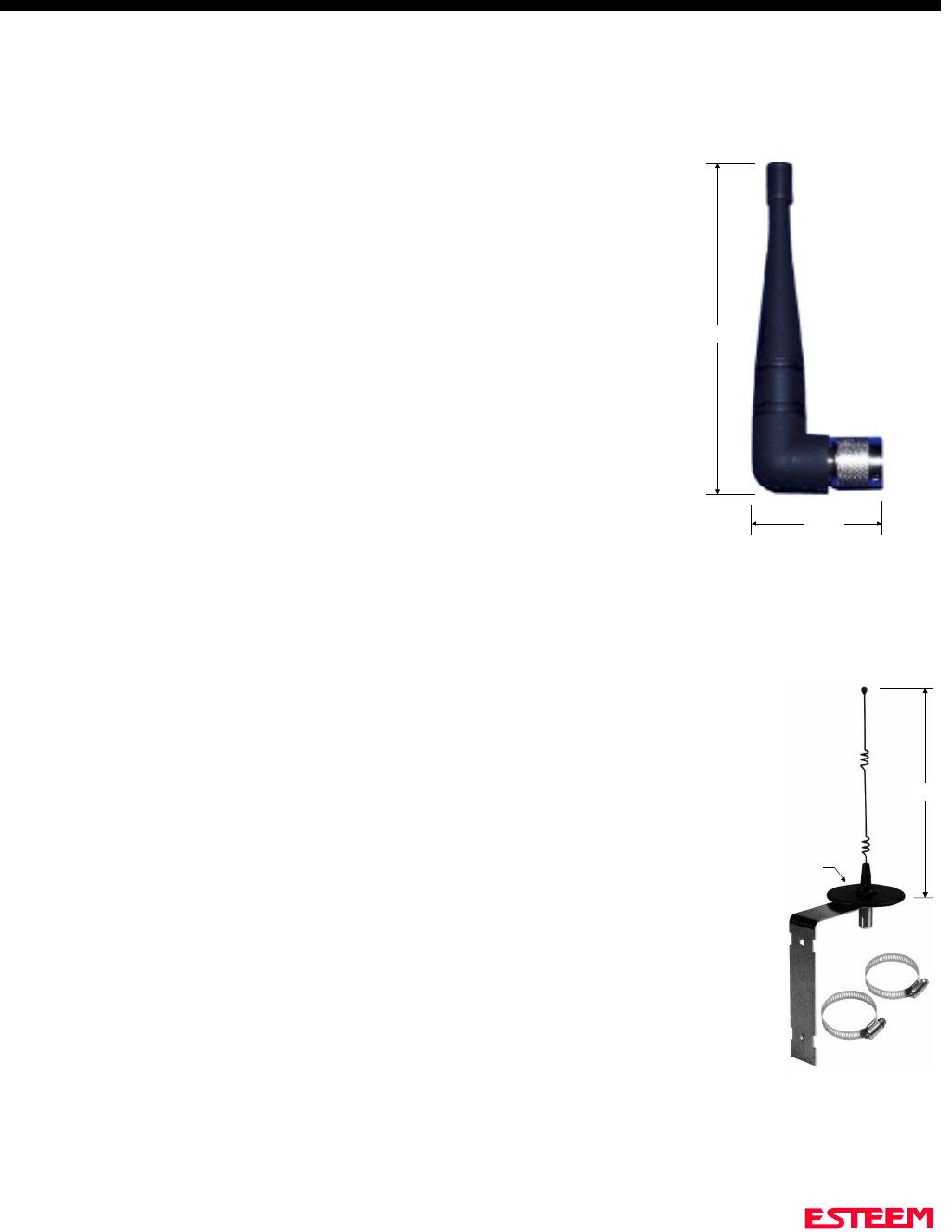
Model No: AA01S
Antenna Type: Omni-Directional, right angle rubber duck, ½ wave
Applications:Back of ESTeem Model 192S mount.
Frequency: 2400 to 24825 MHz
Polarization: Vertical
Impedance: 50 ohms
Gain: 3 dBd
VSWR: < 1.5
Front To Back Ratio: n/a
Horizontal Beamwidth: n/a
Vertical Beamwidth: n/a
Antenna Material: Rubber duct whip.
Mounting Hardware: n/a
Antenna Connector:TNC-R Male
Antenna Envelope: 4 in. length by 1.5 in width
Weight: .08 lbs.
Model No: AA20S
Antenna Type: Omni Directional, 5/8 Wave over 5/8 Wave over ¼ Wave.
Applications:Fixed base or mobile mount.
Frequency: 2400 to 2485 MHz
Polarization: Vertical
Impedance: 50 ohms
Gain: 5 dBd
VSWR: < 1.5
Front To Back Ratio: n/a
Horizontal Beamwidth: n/a
Vertical Beamwidth: n/a
Antenna Material: Stainless steel whip. All other hardware anodized metal.
Mounting Hardware: Stainless steel clamps for mounting to ¾ in. to 1½ in. pipe
with right angle mount of direct panel mount..
Antenna Connector:N Female.
Antenna Envelope: 9 in. length by 3.5 in. width
Weight: .4 lbs.
3.5 in. Dia.
Right Angle
Mounting
Bracket
Stanless
Steel
Clamps
9 in.
Model AA20S
4 in.
1.5 in.
Model AA01S

APPENDIX B
SPECIFICATIONS
Model 192S Antennas
Revised: 11 Feb 99 APX B-3
Model No: AA202S
Antenna Type: Directional, 15 element yagi in sealed UV
stable radome
Applications:Fixed base.
Frequency: 2400 to 2500 MHz
Polarization: Linear
Impedance: 50 ohms
Gain: 13.9 dBd
VSWR: < 1.5
Front To Back Ratio: 18 dB
Horizontal Beamwidth: 34 degrees
Vertical Beamwidth: 30 degrees
Antenna Material: Stainless hardware with one piece copper
radiating element. Advanced microwave
substrate. All other hardware anodized
metal.
Mounting Hardware: Stainless steel U bolts for mounting to 1.5
in. to 2.2 in. diameter pipe.
Antenna Connector:N Female on UltraLink® Pigtail
Maximum Power Input: 50 Watts
Antenna Envelope: 26 in. length by 4.0 in. height by 1.5 in. width
Windload (RWV): 125 mph
Wind Load ½ in. Ice: 100 mph
Wind Surface Area: 0.4 ft2
Weight: 1.25 lbs.
Model AA202S