Elettronika S r l TXUP500 500 Watt Analog TV Broadcast Transmitter User Manual APT139B VEGA Rev0 Date100604
Elettronika S.r.l. 500 Watt Analog TV Broadcast Transmitter APT139B VEGA Rev0 Date100604
Contents
- 1. Users manual Part 1
- 2. Users manual Part 2
- 3. Users manual Exciter part 1
- 4. Users manual Exciter Part 2
- 5. Users manual Exciter Part 3
Users manual Exciter Part 2
57
_______________________________________________________________________________________________
Section 3 - Diagram
Contents:
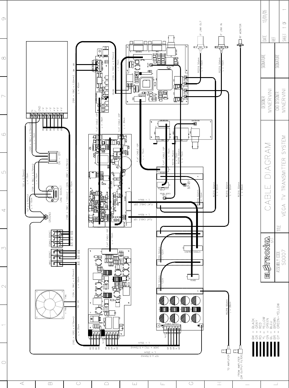
- Cable diagram
- APT139NM2 VEGA Component list
- Modules description
58

59
Part Name Code Description Qty
S0007 MODULAR STRUCTURE 1
MTG0077AR0 POWER SUPPLY MODULE 1
MTG0076AR0 EXTERNAL REFEREMENT MODULE 1
MTG0078AR0 MULT. AUDIO STEREO MODULATOR - OPT. 1
MTG0072AR0 MULT. VIDEO MODULATOR MODULE 1
MTG0073AR0 MULT. IF PRECORRECTOR MODULE 1
MTG0084AR0 MULT. LOCAL OSCILLATOR MODULE 1
MTG0075AR0 MULT. CHANNEL FILTER MODULE 1
MTG0079AR0 DISPLAY AND POWER SUPPLY MODULE 1
MTF0088BR0 15W UHF AMPLIFIER MODULE 1
05352 SAW FILTER SF0036BA01033T (EX 523) B/G 1
OPT016 OPTION NOTCH FILTER UHF VEGA 1
S0007 VEGA Structure
Part Name Code Description Qty
05627 BOARD GUIDE cod. 010Z000 10
05616 FRONT METAL SIDE M 2.5 cod. 000EA084 2
05552B 3-4U HANDLE KIT cod. 235.012 2
DET1010 DET1010R1 DOWN DIN GUIDE FOR VEGA 1
05611A FRONT METAL SIDE cod. 000DA084 2
05611B REAR METAL SIDE cod. 000DA085 2
CON0256 CON0256R0 LEFT SIDE FOR VEGA 1
05609A ANGULAR FOR HANDLE cod. 116ZF001 2
05617 REAR METAL SIDE M 2.5 cod. 000EA085 2
SCH0194AR1 BUS STRUCTURE 1
05636A PERFORATED COVER RACK cod. 405MB084 2
02699 10 WAYS FEMALE CONNECTOR cod. IDS10FSR1 4
02867 20 CONT. FEMALE CONNECTOR cod. IDS20FSR1 4
02884 6 WAYS MALE KSC 6 EXTR. CLAMP-HOLDER 2
02881 4 WAYS MALE KSC 4 EXTR. CLAMP-HOLDER 2
02897 2 WAYS MALE 90° KSCO2 EXTR. CLAMP-HOLDER 1
VEN00004 PAPST FAN mod. 4184NXH 24V 1
07596 FAN GRID LZ 201 1
DET0875I DET0875R1 CONVEYER FAN FOR VEHA INOX P.2678 1
CON0239 CON0239R0 RIGHT SIDE FOR VEGA 1
08878 RG316 50W 41626-SMB 90° 260mm DIN CABLE 1
08879 RG316 50W 41626-SMB 220mm DIN CABLE 2
08880 RG316 50W 41626-41626 120mm CABLE 3
DET1056 DET1056R1 UP DIN GUIDE FOR VEGA 1
02513 SMB 90° R114186000 SOCKET 1
02515 SMB R114313000 SOCKET 1
08502 RG316 50W CABLE 1
Component list APT139NM2 - VEGA
60
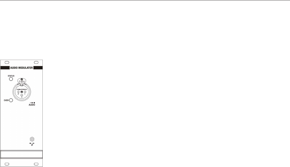
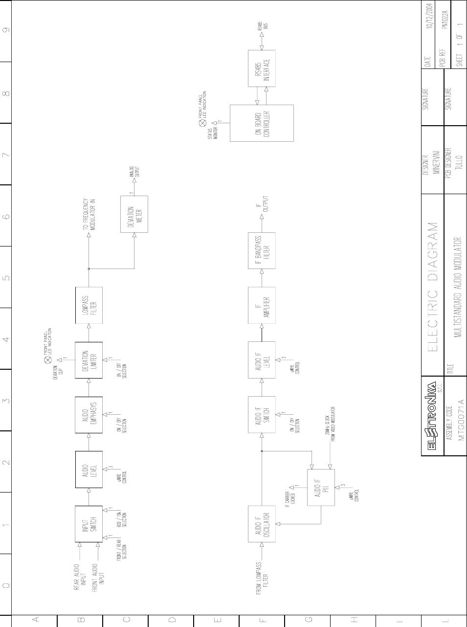
MULT. AUDIO MONO MODULATOR MODULE MTG0071AR1
DESCRIPTION
The audio signal enters the module through one 600W balanced or 10kW unbalanced
XLR connection, which may be placed either on the front or rear panel and software-
selected. It is conditioned by a digital power-meter with a ±8dB 0.5dB-step dynamic and
muting. Then there are the emphasis and clipping stages (which can be inserted via software),
before the frequency modulation of the audio carrier.
The control system of the audio subcarrier is a PLL which locking frequency can be selected
via software depending to the transmission standard, while the reference frequency comes
from the video module.
The control frequency comes from a VCTCXO inside the module to foresee the possibility
of a separated-audio system, for which the 20MHz may be locked to a more precise
system coming from the 5/10MHz bus.
The carrier obtained this way is modulated in frequency and level-conditioned by an IF gain stage trough a
digital power-meter with a ±3dB dynamic in fine tuning before being added to the video carrier.
The following control signal for the modulator operation are present on the board: PLL lock status of the
audio subcarrier, Overload on the audio input, Peak level of the deviation of the audio subcarrier.
All of the operating parameters of the board are managed by the built-in micro-processor. Communication to
outside are performed trough RS485 bus.
TECHNICAL CHARACTERISTICS
Input impedance 600W - 10kW selectable
Nominal level 2Vpp -¥/+8dB
Input Front and back XLR selectable
Emphasis FLAT-50msec (FLAT-75usec)
Deviation limiter Selectable
Low-pass filter 15kHz excludible
Frequency response < ±0.5dB
THD < 0.5%
Intermodulation < 60dB (d2,d3)
Synchronous AM S/N > 50dB
Asynchronous AM S/N > 70dB
FM S/N CCIR > 72dB
Analog measures Carrier FM deviation
Carrier frequency synthesis PLL
Audio carrier characteristics On/Off selection and level adjustment > ±3dB
Frequency reference Internal TCXO externally lockable
External interface Microprocessor with RS485 protocol
Firmware Re-configurable through RS485
61

62
The module contains the following blocks:
1. Input relay chooses the audio source between the XLR on the front panel of the module and the one
on the back of the apparatus and selects the input impedance to 600W or 10kW; both switching are
managed by the software.
2. Audio level regulation stage regulates the level of the audio signal by means of a digital potentiometer
which can be programmed trough a uWIRE interface (with 0.5dB step between -8dB and +8dB).
3. Emphasis stage inserts an emphasis curve on the audio signal with a time constant depending on the
standard (50,75us); the choice can be selected via software.
4. Deviation limiter cuts the audio level to limit the FM deviation; its intervention is handled by the
software and the intervention of the clipper, if any, is signalled by a red LED on the front panel.
5. Low-pass filter filters the audio signal before the modulation to suppress external residues from the
audio band (20Hz-15kHz); the filter can be inserted by means of jumpers on the board.
6. Audio signal level measurement this stage detects the peak level of the audio signal providing a
conditioned analog voltage for the A/D conversion; the voltage will be processed by the microcontroller
of the display board (see MTG0079) to be shown as VU-METER.
7. Frequency modulator converts to intermediate frequency the audio signal as FM modulation of a
carrier.
8. Carrier level regulation stage switches on and off the audio carrier and the regulation within at least
±3dB of the level referring to the video carrier.
9. IF amplifier amplifies the audio carrier to obtain an output level of -6dBm.
10. Output low-pass filter filters the harmonics of the audio carrier.
11. Audio IF oscillator generates the audio carrier performing the PLL frequency synthesis; the selectable
standards and the lock indication are handled by the software.
12. 20MHz reference the frequency reference for the PLL synthesis of the carrier is generated by a
TCXO which may be locked to a more precise 5/10MHz external reference (see MTG0076).
13. Controller all of the described operations are managed by a microcontroller communicating to the user
interface board (see MTG0079) by RS485 protocol; the local controller stores the status of the module
and a reprogramming of the firmware (possible via RS485 from the display board) does not alter its
contents.
63
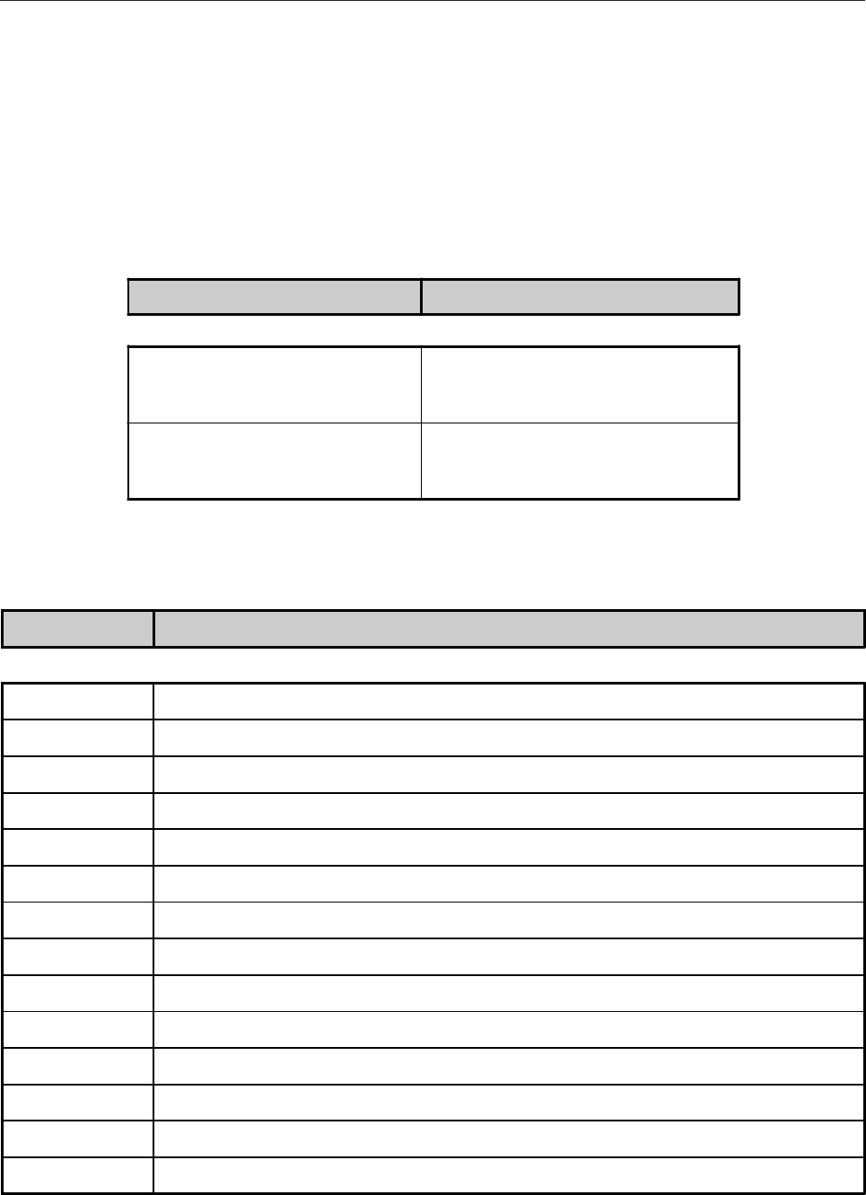
CALIBRATION PROCEDURE
- Instrument list
Description of the adjustment points
MEASURE INSTRUMENT
Lock of the carriers and reference
- Spectrum analyser
- Oscilloscope
- Tester
Calibration of the audio parameters
after the FM modulation
- Audio generator
- FM Audio receiver
- Audio parameters analyser
COMPONENT DESCRIPTION
R6 FM deviation level
R36 Unused
R37 Audio carrier level (-6dBm)
R99 VU-METER deviation
C17 Tuning of the local oscillator of the audio carrier
L5 Fine tuning of the local oscillator of the audio carrier
J7 IF video testpoint (50kHz)
J10 Unused
J3 VCO control voltage testpoint (7...8V)
J6 TCXO testpoint (50kHz)
J11 Unused
J12 External reference testpoint (100kHz)
J2 Audio input (panel)
J5 IF Monitor (panel)
64
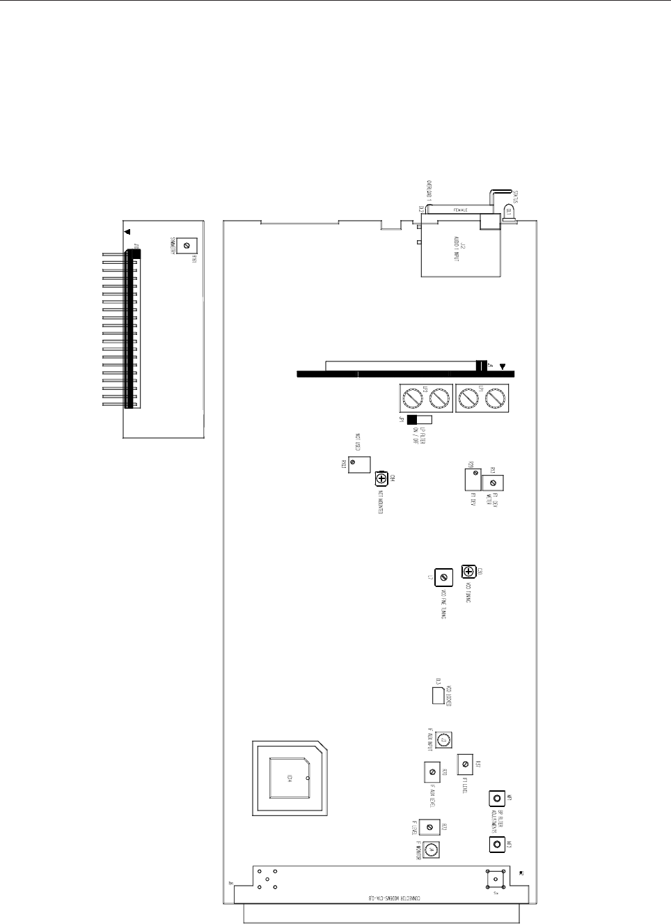
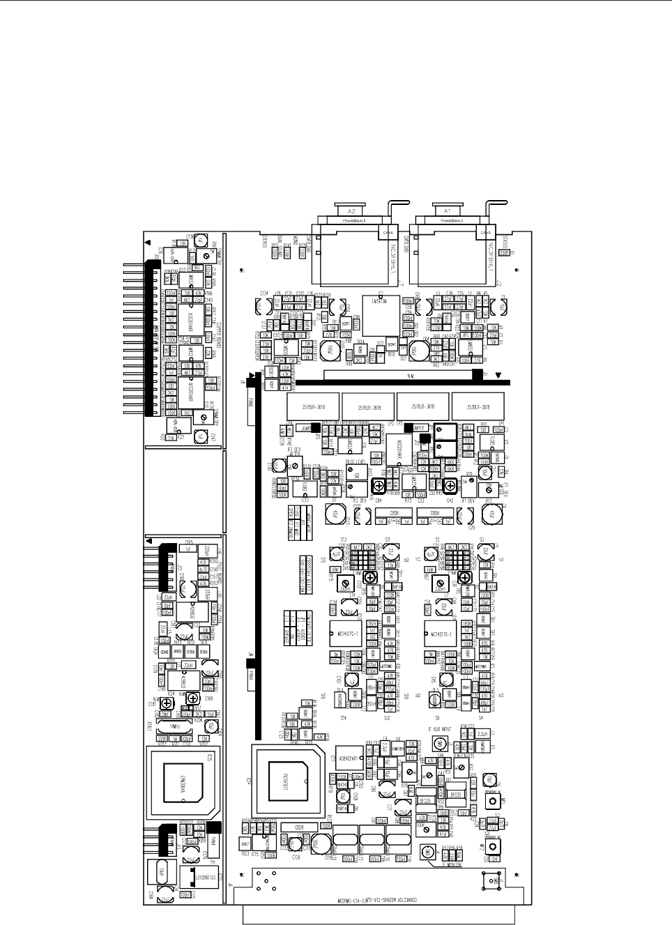
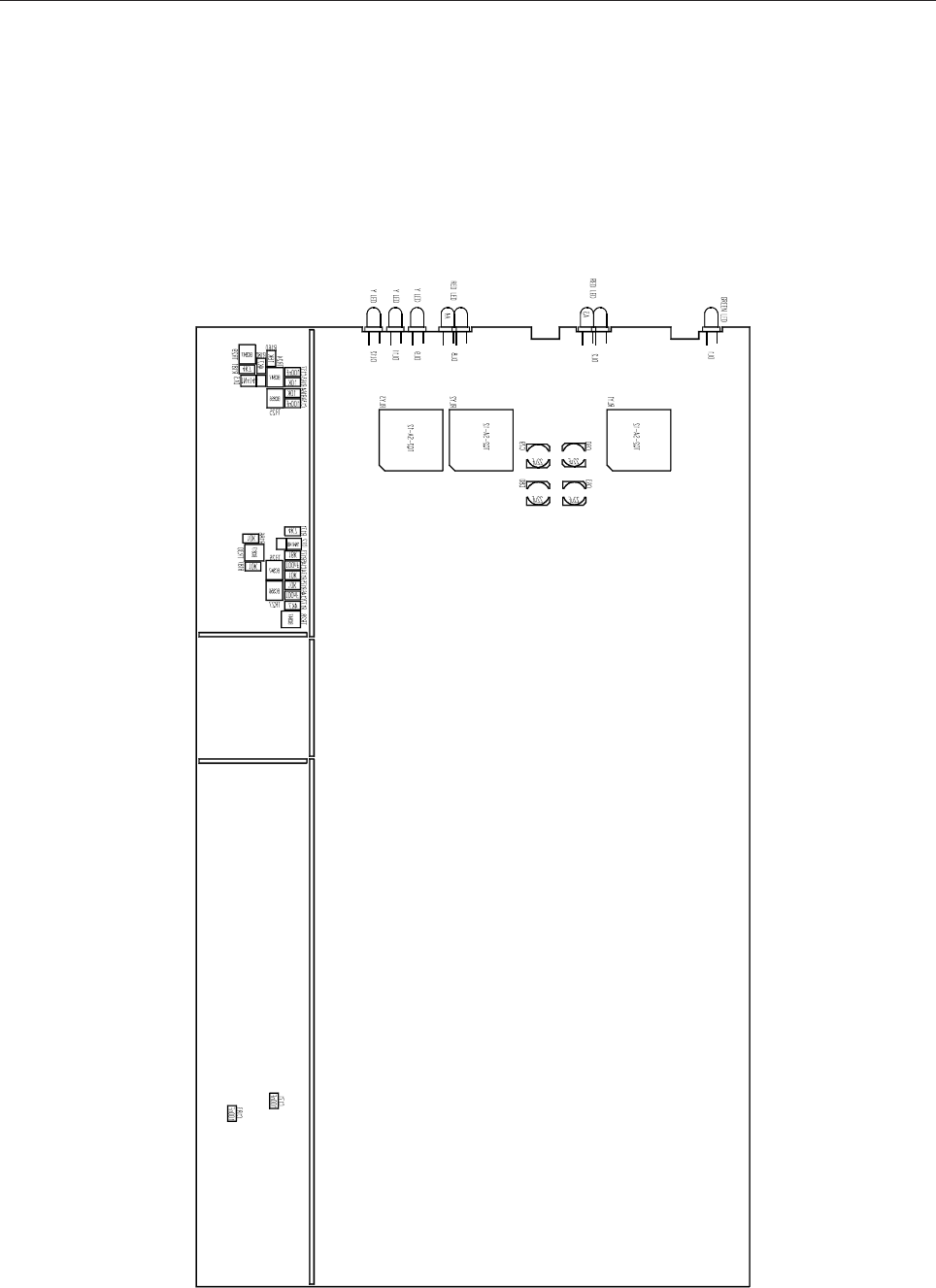
Component layout for adjustment points
65
The calibration procedure of the module requires a complete structure of display board (see MTG0079)
and extension module (see MTG0095) in order to perform the software selection which will be referred
to later and power the module itself.
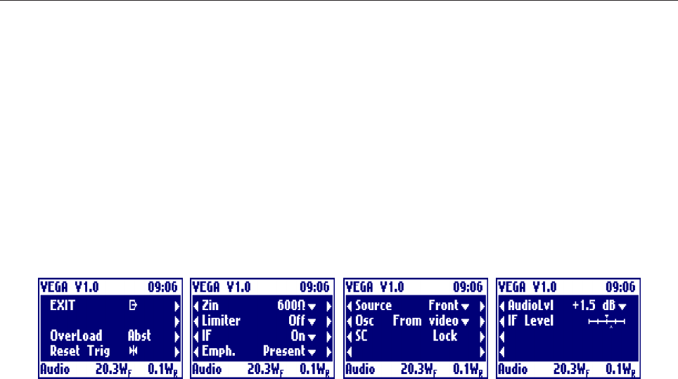
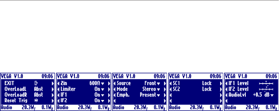
Menu of the Multistandard Mono Audio Modulator Module
Verification of the IF oscillator section connect a spectrum analyser to the monitor of the J5 module
and check the sections in it:
qConfigure the module with IF On and IF Level at ½ of the scale and calibrate C17, L5 to lock the audio
carrier to the intermediate frequency of the set standard (to change the standard refer to the standard
change procedure) and obtain a lock voltage between 7V and 8V on J3, checking that SC is on Lock in
the menu of the display.
qIn case of problems in obtaining the lock, check that on J6, J7 and J12 there are the frequencies listed in
the table of the description of the adjustment points.
Verification of the audio base-band section connect an audio source to J2 and an FM demodulator
with audio parameters measurement capability to the IF monitor of J5 and check the sections in it:
qConfigure the module with Audio Lvl at 0dB, Zin on 600W, Limiter off, Emph present and Source
front.
qCalibrate R6 to obtain the correct level of audio deviation.
qIncrease Audio Lvl to +6dB and set Limiter on, chect that the over LED lighted up and that Overload
indicates Pres, restore Audio Lvl to 0dB and check that the LED becomes unlit and Overload indicates
Trig, if needed reset this indication with Reset Trig and check that it goes to Abst.
qCalibrate R99 for the correct indication of the VU-METER.
66
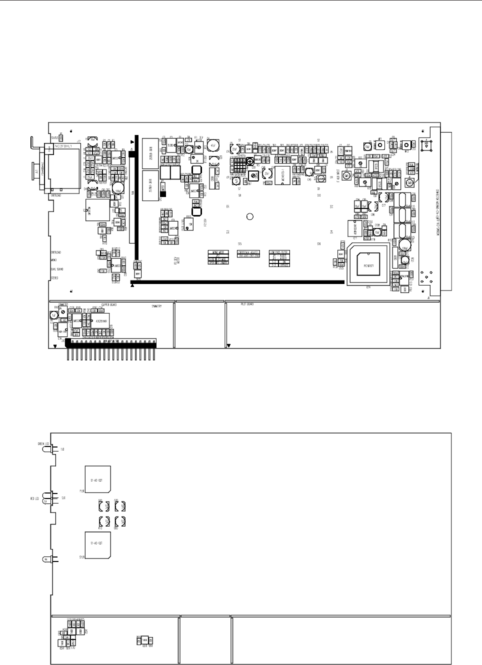
Component layout SCH0198AR3 - Bot layer
Component layout SCH0198AR3 - Top layer
67
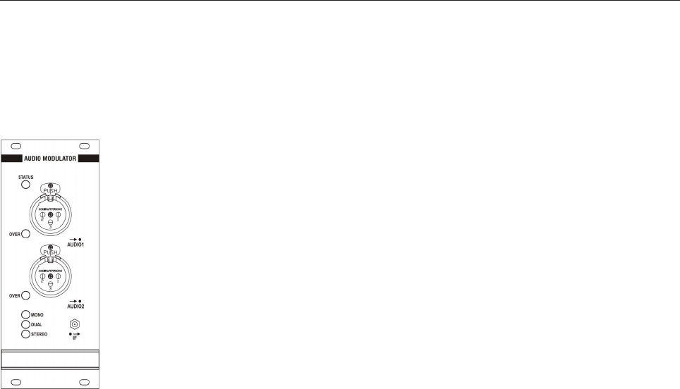
MULT. AUDIO STEREO MODULATOR MODULE (Option) MTG0078AR0
DESCRIPTION
This modulator allows the Mono, Stereo and Dual Sound coding of TV audio signal.
The boards accept two input audio channels with a nominal amplitude of 2Vpp ±8dB on
a selectable impedance of either 600W balanced or 10kW unbalanced. The selection of
the input impedance is made by means of a relay, the adjustment of the input level is made
by means of a digital power-meter. The audio inputs are trough balanced XLRF audio
connectors on the front panel or trough the bus connector. The audio source, either from
front or back, is switched by a relay.
The modulator allows to add a pre-emphasis circuit, which time constant can be set in
factory to either 50 or 75 microseconds.
It is possible to add a deviation circuit to prevent an overdrive of the modulator by an
excessive-level base-band signal.
The base-band audio signals are limited in frequency through low-pass filters which suppress frequencies
higher than 15kHz.
The deviation level is monitored by two peak detectors, one for each audio channel.
The Mono, Stereo or Dual Sound coding is analog. The pilot tone identifying the codification is overlapped to
the audio signal which modulates the secondary audio subcarrier. This tone is represented by a 54.6875kHz
pilot frequency, synthesised locally and locked by a PLL to the line frequency of the video signal in base band.
The coding requires this pilot frequency to be non-modulated for monophonic audio. The pilot frequency is
AM modulated with a frequency equal to 117.5Hz, 50% modulation depth, for Stereo. It is AM modulated
with a frequency of 274.1Hz, 50% modulation depth, for Dual Sound audio.
The coded audio signal modulates the two subcarriers generated by the VCO, PLL locked to a reference
frequency of 20MHz. Each of the subcarriers can be disabled, and the nominal level can be changed by
±3dB. On the board there is an IF input for the 38.9MHz video carrier. The latter is added to the two audio
subcarriers and sent to the output.
The following control signal for the modulator operation are present on the board:
- PLL lock status of the primary audio subcarrier.
- PLL lock status of the secondary audio subcarrier.
- PLL lock status of the pilot tone.
- Overload on the main audio input.
- Overload on the secondary audio input.
- Peak level of the deviation of the primary audio subcarrier.

68
- Peak level of the deviation of the secondary audio subcarrier.
All of the operating parameters of the board are managed by the built-in micro-processor. Communication to
outside are performed trough RS485 bus.
TECHNICAL CHARACTERISTICS
Input impedance 600W - 10kW selectable
Nominal level 2Vpp -¥/+8dB
Input Front and rear XLR selectable
Emphasis FLAT-50msec (FLAT-75usec)
Deviation limiter Selectable
Low-pass filter 15kHz excludable
Frequency response < ±0.5dB
THD < 0.5%
Stereo crosstalk < -40dB
Intermodulation < 60dB (d2,d3)
Synchronous AM S/N > 50dB
Asynchronous AM S/N > 70dB
FM S/N CCIR > 72dB
Analog measures FM deviation of the carriers
Carrier frequency synthesis A PLL
Audio carrier characteristics On/Off selection and level adjustment > ±3dB
Pilot tone characteristics 54687.5Hz (3/2fs) ±10Hz
Pilot tone modulation AM 50%
Modulation frequency 274.12Hz (1/57fs) 117.48Hz(1/133fs)
Frequency reference Internal TCXO externally lockable
External interface Microprocessor withRS485 protocol
Firmware Re-configurable via RS485
69

70
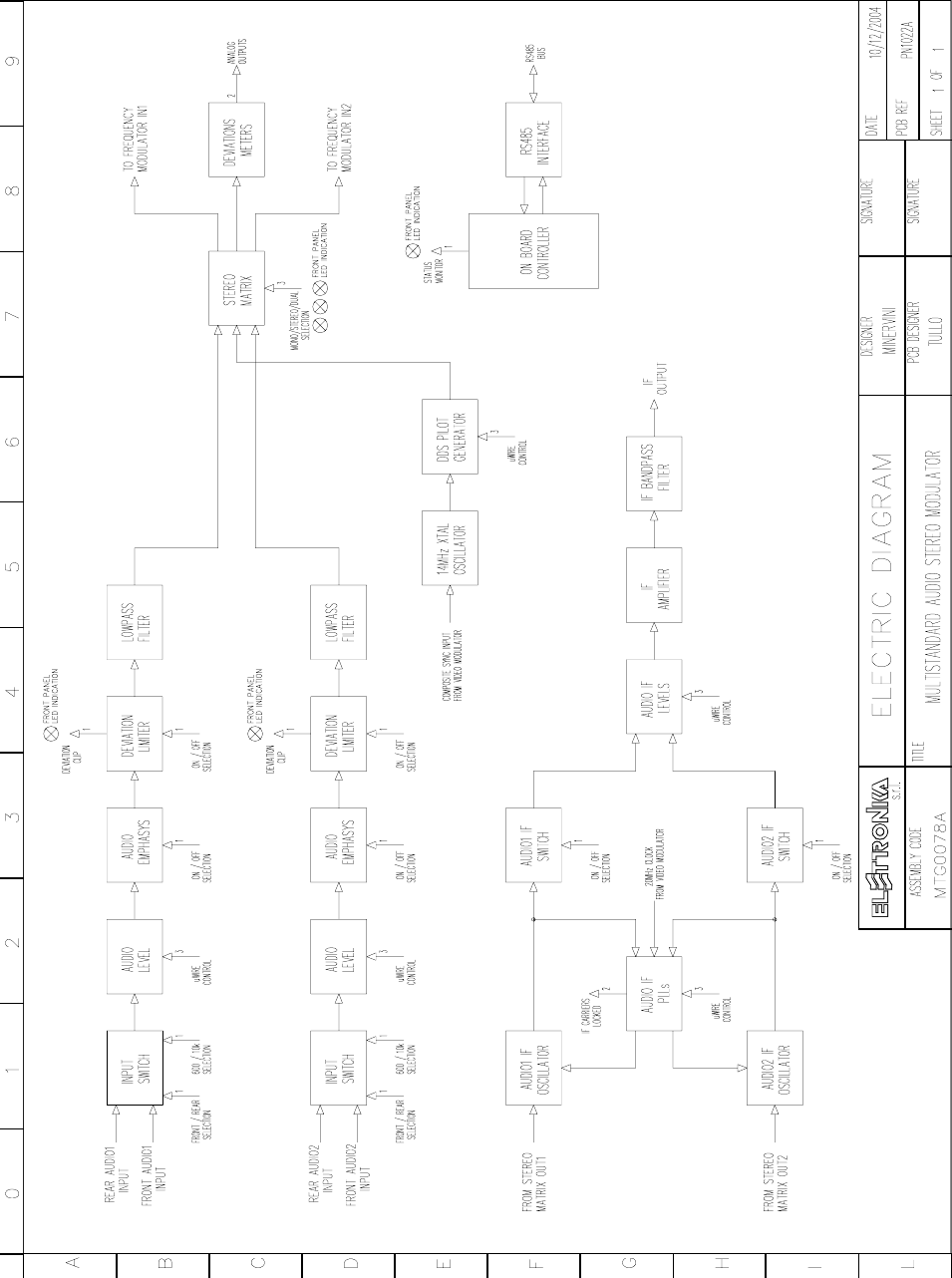
The module contains the following blocks:
1. Input relays (2) chooses the audio source between the XLR on the front panel of the module and the one on
the back of the apparatus and selects the input impedance to 600W or 10kW; both switching are managed by
the software.
2. Audio level regulation stages (2) regulates the level of the audio signal by means of a digital potentiometer
which can be programmed trough a uWIRE interface (with 0.5dB step between 8dB and +8dB).
3. Emphasis stages (2) inserts an emphasis curve on the audio signal with a time constant depending on the
standard (50,75us); the choice can be selected via software.
4. Deviation limiters (2) cuts the audio level to limit the FM deviation; its intervention is handled by the
software and the intervention of the clipper, if any, is signalled by a red LED on the front panel.
5. Low-pass filters (2) filters the audio signal before the modulation to suppress external residues from the
audio band (20Hz-15kHz); the filter can be inserted by means of jumpers on the board.
6. Stereo matrix encodes the two audio signals depending on the transmission mode set and adds the modulated
pilot tone to define the transmission standard as either mono, stereo or dual sound; the selection can be made
via software and is indicated by three yellow LEDs on the frontal panel.
7. 14MHz quartz oscillator generates the clock needed to synthesise the pilot tone locked to the line-synchronism
frequency of the video signal coming from the video modulator module (see MTG0072).
8. Synthesised pilot tone generator synthesises the pilot tone by means of DDS programmed trough an
uWire interface.
9. Audio signal level measurement this stage detects the peak level of the audio signal providing two conditioned
analog voltages for the A/D conversion; the voltages will be processed by the microcontroller of the display
board (see MTG0079) to be displayed as VU-METERS.
10. Frequency modulators (2) converts to intermediate frequency the audio signal as FM modulation of a
carrier.
11. Carrier level regulation stages (2) switches on and off the audio carrier and the regulation within at least
±3dB of the level referring to the video carrier.
12. IF amplifier amplifies the audio carrier to obtain an output level of -6dBm.
13. Output low-pass filter filters the harmonics of the audio carrier.
14. Audio IF oscillators (2) generates the audio carrier performing the PLL frequency synthesis; the selectable
standards and the lock indication are handled by the software.
15. 20MHz reference the frequency reference for the PLL-synthesis of the audio carrier is obtained from the
video module (see MTG0072) to keep a perfect intercarrier lining.
16. Controller all of the described operations are managed by a microcontroller communicating to the user
interface board (see MTG0079) by RS485 protocol; the local controller stores the status of the module and a
reprogramming of the firmware (possible via RS485 from the display board) does not alter its contents.
71
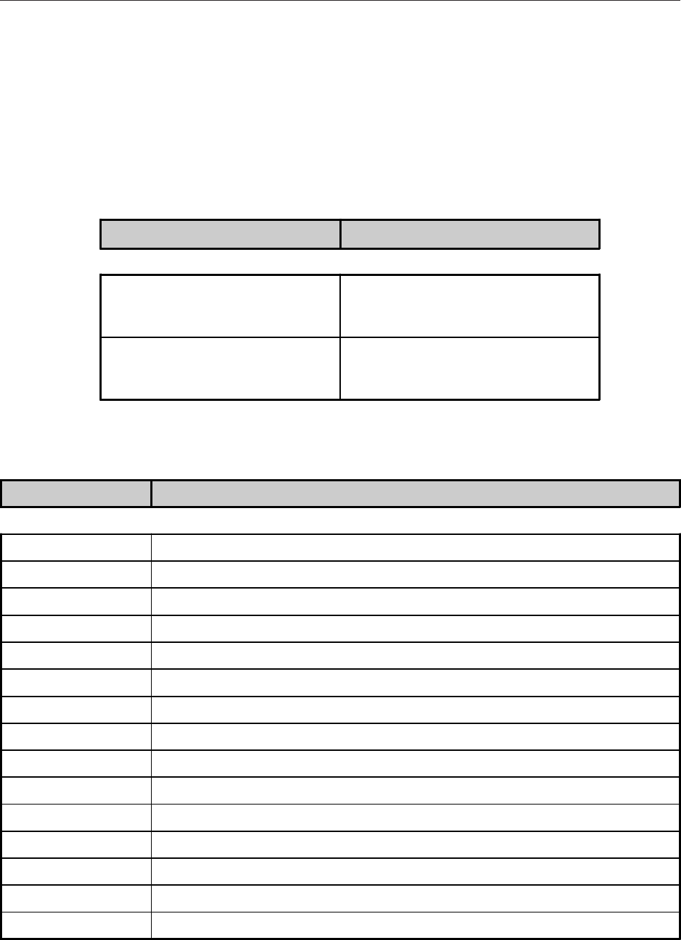
CALIBRATION PROCEDURE
- Instrument list
- Description of the adjustment points
MEASURE INSTRUMENT
Lock of the carriers and reference
- Spectrum analyser
- Oscilloscope
- Tester
Calibration of the audio parameters
after the FM modulation
- Audio generator
- FM Audio receiver
- Audio spectrum analyser
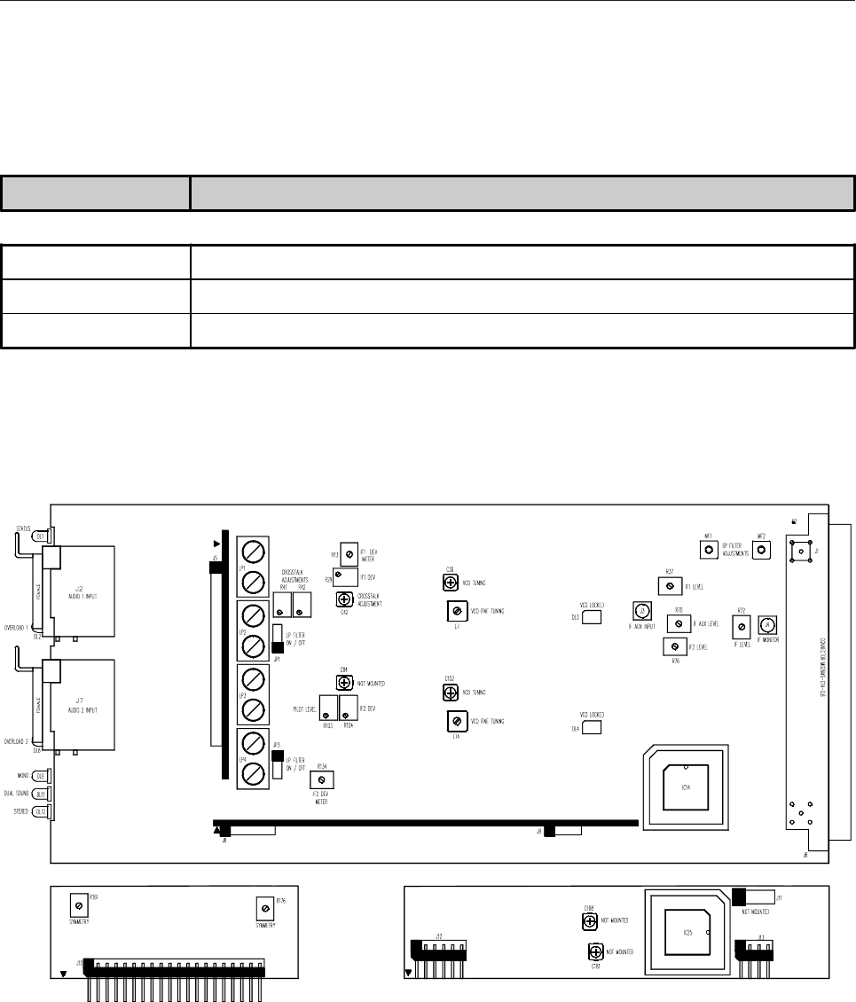
COMPONENT DESCRIPTION
R161 Clipper symmetry, left channel
R176 Clipper symmetry, right channel
R13 Indication of the main carrier deviation
R134 Indication of the secondary carrier deviation
LP1, LP2, LP3, LP4 Frequency response adjustment
R41, R42, C42 Crosstalk adjustment
R103 Pilot tone level adjustment
R29 Adjustment of the main carrier deviation
R104 Adjustment of the secondary carrier deviation
C30, L7 Adjustment of the main carrier frequency
C102, L14 Adjustment of the secondary carrier frequency
R37 Adjustment of the main carrier output level
R76 Adjustment of the secondary carrier output level
R70 Adjustment of the video carrier (Unused)
R72 Adjustment of the carriers output level
72
Component layout for adjustment points
COMPONENT DESCRIPTION
MF1, MF2 Adjustment of the output filter
J2, J7 Audio inputs (panel)
J4 IF monitor (panel)
The calibration procedure of the module requires a complete structure of display board (see MTG0079)
and extension module (see MTG0095) in order to perform the software selection which will be referred
to later and power the module itself.
73
- Menu of the Multistandard Stereo Audio Modulator Module
Verifica sezione oscillatore a IF collegare un analizzatore di spettro sulla monitoria del cassetto J5 e
controllare la funzionalità delle sezioni in esso presenti:
qConfigure the module with IF1 and IF2 On and IF1 Level and IF2 Level at ½ of the scale and
calibrate C30 and L7 (C102 and L14) to lock the audio carriers to the intermediate frequency of the set
standard (to change the standard refer to the standard change procedure) and obtain a lock voltage
between 2V and 3V on C4 (C113), checking that SC1 and SC2 are on Lock in the menu of the display.
qConnect a spectrum analyser in tracking mode between J3 and the output of the J1 module and check
the response of the filter calibrating MF1 and MF2 to the minimum ripple.
qCalibrate the R37 trimmer to obtain on J1 the maximum level of the main carrier in output and calibrate
R76 for a level of the secondary carrier -7dBc compared to the main, then calibrate R72 to obtain a level
of the main carrier of -6dBm.
Verification of the audio base-band section connect an audio source to J2 and J7 and an FM
demodulator with audio parameters measurement capability to the IF monitor of J4 and check the sections in
it:
qConfigure the module with Mode DualSound, Audio1 Lvl 0dB, Audio2 Lvl 0dB, Zin 600W, Limiter
off, Emph present and Source front.
qCalibrate R29 and R104 to obtain the correct level of audio deviation for both subcarriers.
qIncrease Audio1(2) Lvl to +6dB set Limiter on, chect that the over LED lighted up and that
OverloadL(R) indicates Pres, and that the limitation circtuit acts symmetrically on both polarities of the
audio signal, using an oscilloscope on pin3 of JP1 (JP3), and retouch if needed R161 (R176), restore
Audio1(2) Lvl to 0dB and check that the LEDs become unlit and OverloadL(R) indicates Trig, if
needed reset this indication with Reset Trig and check that it goes to Abst.
qCalibrate R13 and R134 for the correct indication of the VU-METERS.
qConfigure the module with Mode Mono and calibrate R103 to a 2.5kHz deviation of the pilot tone with
no audio sources connected on J2 and J7.
qConfigure the module with Mode Stereo and connect an audio signal to J7, calibrate R41, R42 and C42
to maximise the crosstalk of the right channel over the left channel.
74
Component layout SCH0210AR1 - Bot layer
75
Component layout SCH0210AR1 - Top layer
76
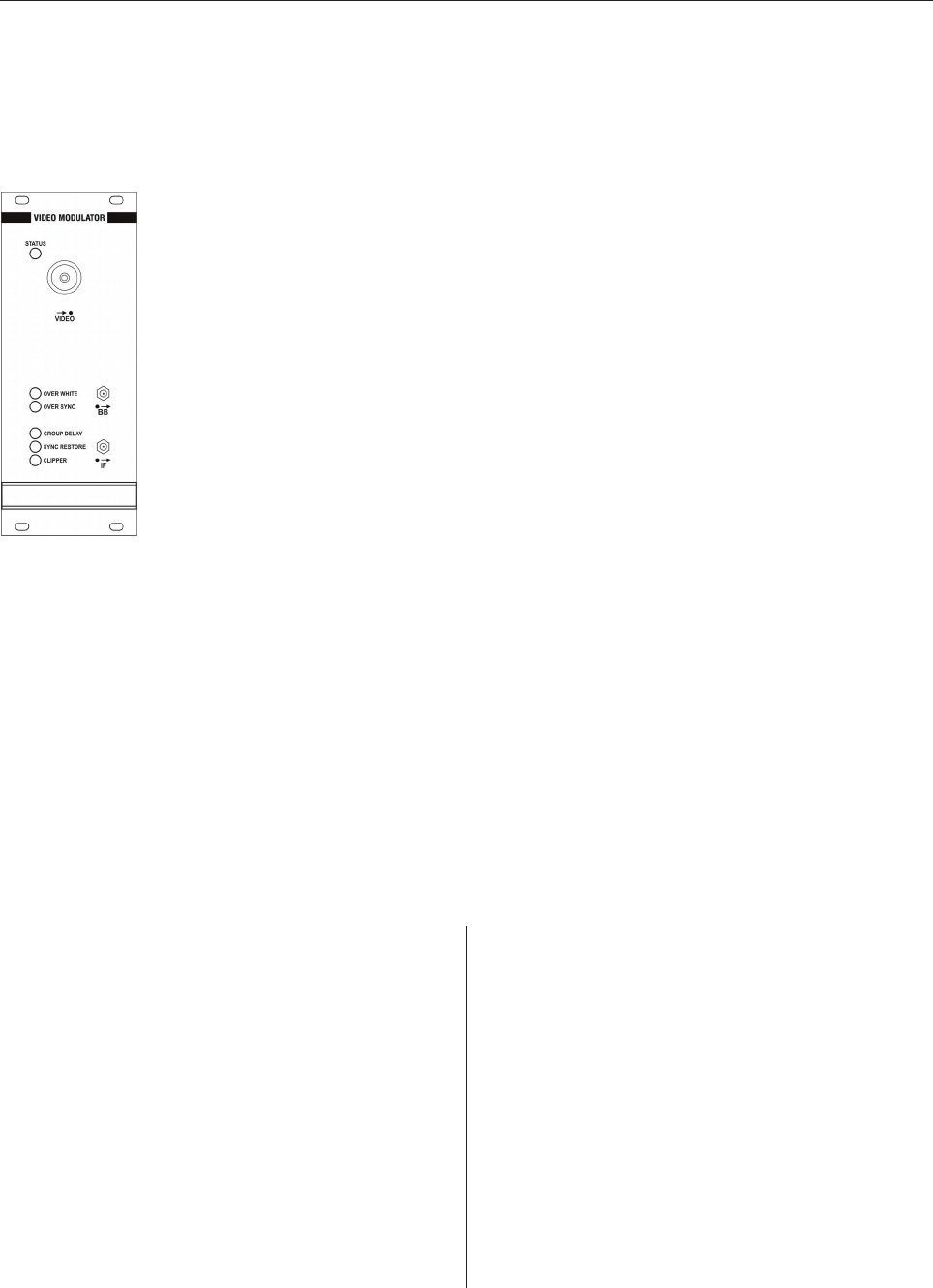
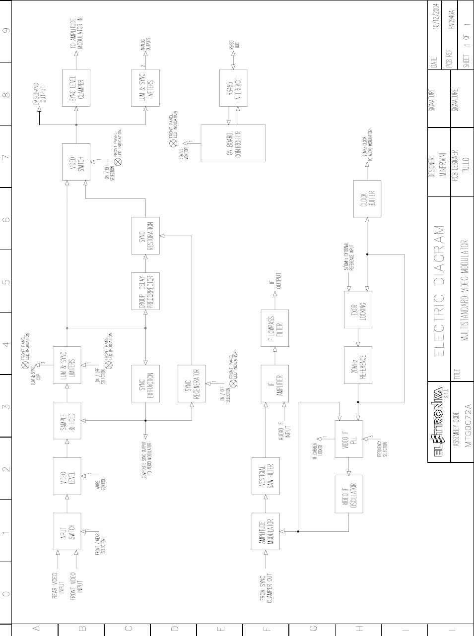
MULT. VIDEO MODULATOR MODULE MTG0072AR0
DESCRIPTION
The video signal enters the module trough a 75W BNC connection which can be selected
via software on either the front or rear panel of the apparatus, and is conditioned to the
standard value of 1Vpp by a digital power-meter with a maximum dynamic of +/-6dB. A
sample&hold system allows to set the black level independently from the video information
in order to perform clipping operations of the synchronism and luminance levels (which
can be disabled via software).
An electronic switch (selectable via software) allows to add the video pre-correction stage,
made up by the synchronism regenerator and the video group delay pre-corrector. The
former allows to regenerate a normal synchronism level for remarkably degraded video
signals, while the latter allows to correct the shape of the audio trap contained in the TV
receivers. If the synchronism regenerator is not needed, it can be disabled even if the video
pre-correction stage is enabled, but it cannot be used without the latter. The processed video signal modulates
the amplitude of the audio carrier generated by an internal local oscillator and controlled by a PLL which
locking frequency can be selected via software in accordance with the transmission standard.
The amplitude modulation of the carrier is performed by a Gilbert dell controlled in current to obtain an
effective modulation linearity. After this, there are the vestigial filter and an UF gain stage which also sums the
audio subcarriers, if any. The whole modulation system is locked to an internal 20MHz reference made up by
a VCTCXO, which may in turn be locked to an external 5/10MHz reference present on the control bus, in
case the precision offset support is needed.
This 20MHz reference is also used in the audio modulation module in order to obtain the perfect distance
between the audio and video carriers even without the external precision reference.
TECHNICAL CHARACTERISTICS
Input impedance 75W - ROS>25dB
Nominal level 1Vpp ±6dB
Input Front and back selectable BNC
Group delay < 50nsecpp
Frequency response < ±0.5dB
Differential gain < ±1%
Differential phase < ±2°
Luminance non-linearity < ±2%
k-Factor < 1%
Tilt < 1%
ICPM < 2°
S/HUM > 48dB
S/Nunwgt > 60dB
S/Nwgt > 68dB
Clamping S/H to backporch
Clipper intervention On synchronism and luminance
Synchronism regenerator Effective within ±6dB
Group delay pre-corrector 8-celle, excludible
Analog measures Synchronism and
luminance level
Carrier frequency synthesis PLL
Frequency reference Internal TCXO
externally lockable
External interface Microprocessor with
RS485 protocol
Firmware Riconfigurabile tramite RS485
77

78
The module contains the following blocks:
1. Input relay chooses the video source between the BNC on the front panel of the module and the one
on the back of the apparatus; the switching is managed by the software.
2. Video level regulation stage regulates the level of the video signal by means of a digital potentiometer
which can be programmed trough a uWIRE interface.
3. Clamping stage uses the timing information of the synchronism extraction stage (see below) to perform
the sample & hold of the black level at backporch.
4. Synchronism and luminance limitation clips the synchronism and luminance levels without distorting
the crominance signal; the intervention is handled by the software and shown by a yellow LED on the
frontal panel, the intervention of the clipper, if any, is shown by two red LEDs (one for synchronism and
one for luminance) on the front panel.
5. Synchronism extraction stage extracts from the video signal the synchronism timing to perform the
clamping, the regeneration and the lock of the pilot tone of the stereo audio modulator (see MTG0078).
6. Synchronism regeneration stage starting from the timing information extracted by the previous stage,
this processes a new synchronism pulse corrected both in level, timing and shape (rising and lowering
times); the intervention is handled by the software and signalled by a yellow LED on the frontal panel.
7. Group delay pre-corrector performs the pre-correction of the notch filter on the audio carrier in the
demodulator of the receiver in order to equalise its group delay.
8. Synchronism insertion stage cuts the existing synchronism of the video signal and superimposes the
regenerated one; due to the need of a delay in the video signal to perform the cut compared to the
extraction timing of the synchronism, this stage is related to the insertion of the group delay pre-corrector
which inserts this delay.
9. Video switch this stage chooses between the processed video signal (pre-corrected and regenerated in
synchronism if needed) and the non-processed one, at this stage there is the monitor for the video base
band with 75W output with SMB connector on the frontal panel; the choice is handled by the software
and signalled by a yellow LED on the front panel.
10. Video signal level measurement this stage detects the peak of the synchronism and luminance levels
providing two analog voltages for the A/D conversion; the voltages will be processed by the microcontroller
of the display board (see MTG0079) to be displayed as VU-METERS.
11. Synchronism level clamper once all needed processing have been performed with the clamping at
black level, a new clamping operation at the synchronism level is made in order to perform the subsequent
negative AM modulation.
12. Amplitude modulator converts to the intermediate frequency the video signal referring to the synchronism

79
peak with a modulation depth of 90% at white level.
13. Vestigial SAW filter filters the double side-band to the broadcast carrier in order to obtain a vestigial
modulation (the upper side-band is partially broadcast).
14. IF Amplifier performs the amplification after the vestigial filtering and sums the audio subcarrier(s)
coming from the audio modulator module (see MTG0071/78).
15. Output low pass filter filters the presence of harmonics of the audio and video carriers.
16. IF video oscillator generates the video carrier by performing the PLL frequency synthesis; the selectable
standards and the lock indication are handled by the software.
17. Riferimento a 20MHz the frequency reference for the PLL synthesis of the video carrier is generated
by a TCXO which may be locked to a more precise 5/10MHz external reference (see MTG0076), this
reference is buffered and used as reference by the audio modulator (see MTG0071 /78) to synthesise the
frequency of the audio carrier so that there are no frequency offsets between the two carriers, even when
there is no common external reference.
18. Controller all of the described operations are managed by a microcontroller communicating to the user
interface board (see MTG0079) by RS485 protocol; the local controller stores the status of the module
and a reprogramming of the firmware (possible via RS485 from the display board) does not alter its
contents.
CALIBRATION PROCEDURE
- Instrument list
MEASURE INSTRUMENT
Lock of the carriers and reference
- Spectrum analyser
- Oscilloscope
- Tester
Calibration of the video parameters
in base band
and after the AM modulation
- Video generator with VITS
- AM Video receiver
- Video parameters analyser
80
- Description of the adjustment points
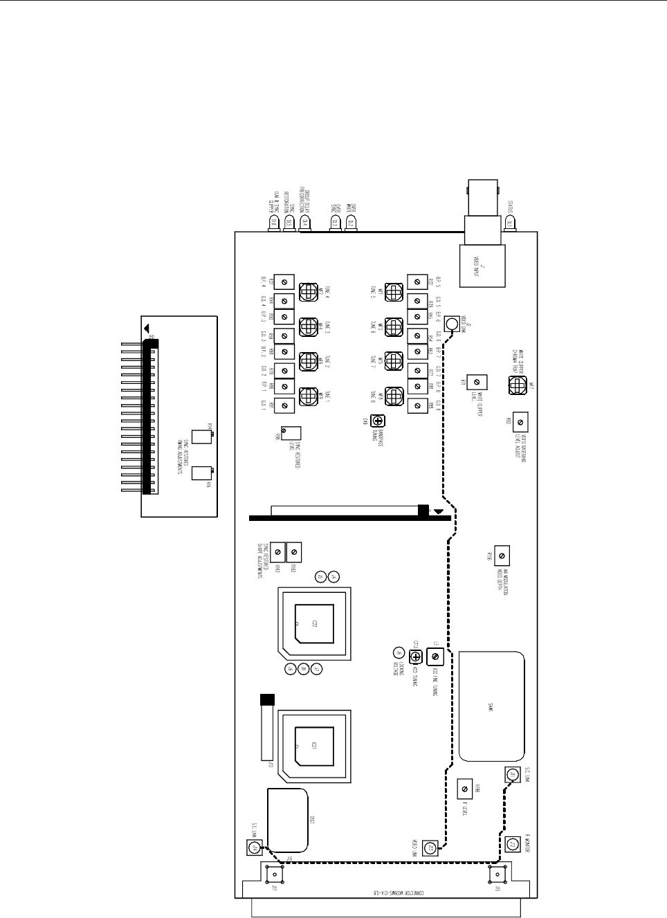
COMPONENT DESCRIPTION
R71 White clipper level
R92 Level of the video signal in base band (0dB on dig. pot.)
R156 AM modulation depth (90%)
R196 Video carrier level (-6dBm)
R32, R45, R63, R81,
R37, R50, R68, R86 Control of the passing band of the pre-corrector cells
R39, R54, R73, R88,
R44, R59, R78, R91 Control of the group delay of the pre-corrector cells
R98 Level of the regenerated synchronism
R14, R16 Timing of the cut window of the synchronism
R162, R163 Shape adjustment of the synchronism
C49 Control of the passing band of the pre-corrector
C113 Tuning of the local oscillator of the video carrier
MF1, MF3, MF5, MF8,
MF2, MF4, MF6, MF9 Tuning of the group delay pre-corrector cells
MF7 Tuning of the filter on the chrome carrier of the white limiter
L5 Fine tuning of the local oscillator of the video carrier
J4 IF video testpoint (50kHz)
J5 Unused
J6 VCO control voltage testpoint (7...8V)
J7 TCXO testpoint (50kHz)
J8 Unused
J9 External reference testpoint (100kHz)
J1 Video input (panel)
J2-J13 Video link for rear input
J11-J14 IF link for audio carrier input
J12 IF monitor (panel)
81
Component layout for adjustment points
82
The calibration procedure of the module requires a complete structure of display board (see
MTG0079) and extension module (see MTG0095) in order to perform the software selection which
will be referred to later and power the module itself.
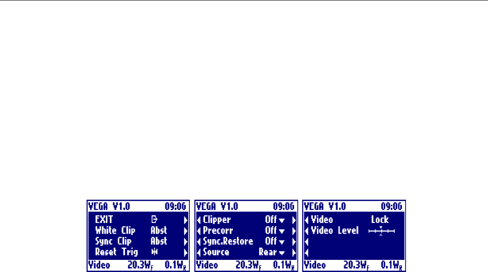
- Menu of the Multistandard Video Modulator Module
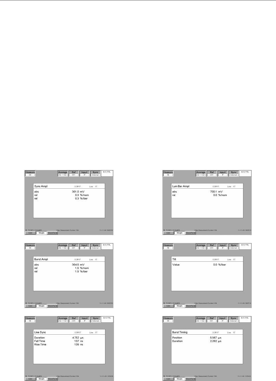
Verification of the video base-band section connect a video source with VITS to J1 and a video
parameter measurer to the video base-band output and check the sections included:
qConfigure the module with Video Level at ½ of the scale, Clipper off, Precorr off, Sync.Restore off
and Source front.
qCalibrate R92 to obtain the correct levels of synchronism (Fig.1), luminance (Fig.2) and color burst
(Fig.3).
qIncrease Video Level to ¾ of the scale and set Clipper to on, calibrate R71 for the intervention of the
white limitation circuit, check that the over LEDs light up and that White Clip and Sync Clip are on
Pres, restore Video Level to ½ of the scale and check that the LEDs become unlit and that White Clip
and Sync Clip are on Trig, if needed reset this indication by means of Reset Trig anc check that White
Clip and Sync Clip are on Abst.
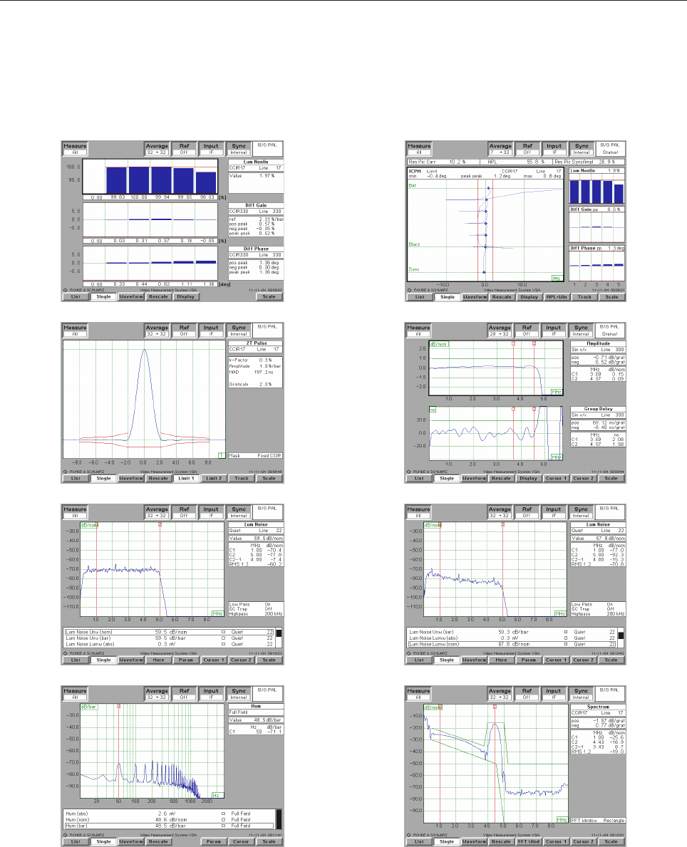
qConfigure the module with Precorr on and calibrate R39, R54, R73, R88, R44, R59, R78 and R91
to obtain the desired group delay mask, if needed calibrate R32, R45, R63, R81, R37, R50, R68,
R86 and C49 to make the passing band flat; in case this cannot be done in the base band (the video
parameters analyser has no group delay mask for the required standard) the calibration of the IF pre-
corrector can be made using the AM receiver set with the trap on the audio carrier enabled, equalising the
group delay in order to make it flat as in Fig.10 (thus automatically compensating the trap on the audio
carrier of the receiver).
qConfigure the module with Sync.Restore on and calibrate R14 and R16 for the correct timing of the
synchronism pulse (Fig.5) and color burst (Fig.6) and R98 for the correct level of the synchronism
(Fig.1); only if needed, calibrate R162 and R163 to equalise the rising and lowering time of the synchronism
pulse.
Verification of the IF oscillator section connect a spectrum analyser on the monitor of the J12 module
and check the sections within:
83
Fig. 1 Fig. 2
Fig. 3 Fig. 4
Fig. 5 Fig. 6
qCalibrate C113 and L5 to lock the video carrier to the intermediate frequency of the set standard (to
change the standard refer to the standard change procedure) and obtain a lock voltage between 7V and
8V on J6 checking that Video is on Lock in the display menu.
qIn case of problems in obtaining the lock, check that on J4, J7 and J9 there are the frequencies listed in
the table of the description of the adjustment points.
Verification of the AM modulation section connect a video source with VITS to J1, a spectrum
analyser to the monitor of the J12 module and an AM video receiver with video parameters analyser to the
output of the J15 module, anc check the sections within:
qCalibrate R196 for a level of 6dBm of the video carrier and check that the video parameters described
in the technical specifications table are obtained (see Fig.1 to Fig.14).
84
Fig. 7 Fig. 8
Fig. 9 Fig. 10
Fig. 11 Fig. 12
Fig. 13 Fig. 14
85
Component layout SCH0172AR3 - Top Layer
Component layout SCH0172AR3 - Bot Layer
86
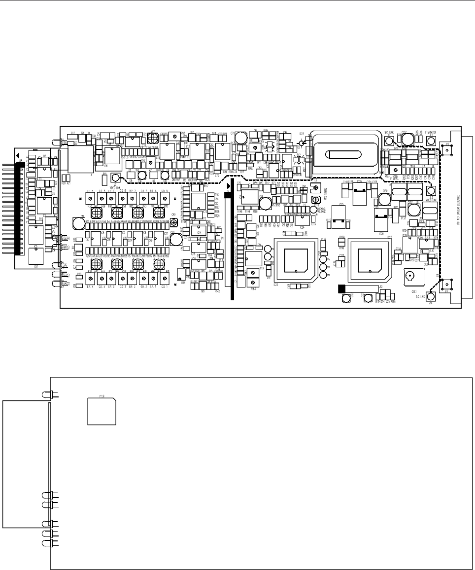
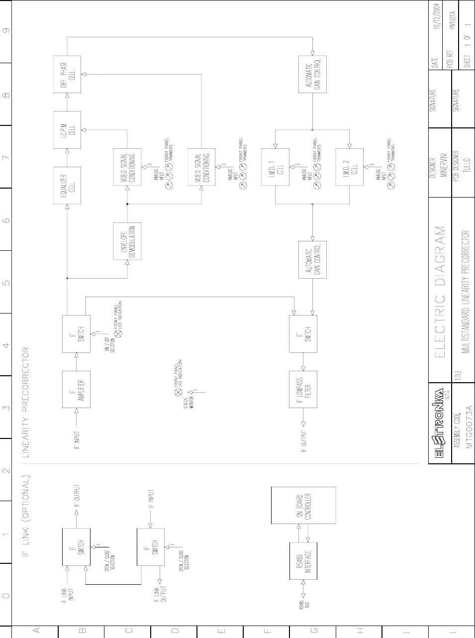
MULT. IF PRECORRECTOR MODULE MTG0073AR0
DESCRIPTION
The non-linearity IF pre-correction is performed by two distinct stages which act on different
characteristics of the signal. The first stage works on ICPM and differential phase and gain
(DGDP) of the video signal, which are small signal characteristics and thus need a pre-
correction based on adapted filtering cells.
The second stage works on intermodulation, which is a large signal characteristic and
needs a pre-correction based on the intervention on non-linear stages.
In consideration of this, the work of the second stage is assured by am automatic gain
control system which comes before and after the correction cells, and which is needed to
have the system work correctly for each type of pre-correction adopted.
The whole pre-correction stage can be enabled and disabled via software with a switching
system which prevents the overshoot at IF-level, dangerous for the final stages.
TECHNICAL CHARACTERISTICS
Input impedance 50W - ROS > 25dB
Output impedance 50W - ROS > 25dB
Nominal level -6dBm
Group delay < 10nsecpp
Frequency response < ±0.2dB
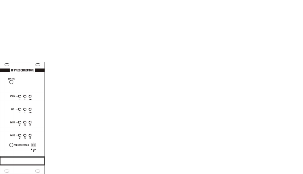
I.C.P.M. pre-correction 3 cells: (-) (+) (level)
D.P. pre-correction 3 cells: (-) (+) (level)
IMD1 pre-correction 3 cells: (knee) (slope) (phase)
IMD2 pre-correction 3 cells: (knee) (slope) (phase)
Video signal for ICPM and DP Internal envelopment demodulator
Automatic gain control Before and after the IMD1 cells, 2
Pre-correction Excludible via software
Pre-corrector intervention Can be enabled even when powered, without overshoot
Analog measures ---
87

88
The module contains the following blocks:
1. Input amplifier de-couples the input of the module from the internal pre-correction sections.
2. Input/output relay inserts or excludes the pre-corrector from the IF chain with the timing needed to avoid
power overshoot due to the internal AGC stages; the switch is handled by the software and signalled by a
yellow LED on the frontal panel.
3. Envelopment demodulation stage extracts the video information from the AM modulation in order to
process the interventions on the pre-correction of ICPM and DP.
4. Conditioning stages of the video signal (2) these use the information extracted by the demodulator and
process it by inserting some deformation stages of the video signal which parameters (lower cut, upper cut and
level) depend on the controls on the frontal panel.
5. Equalisation cell equalises the passing band of the IF pre-corrector by inserting a band-pass filter cell
between the ICPM (set on the video carrier) and DP (set on the audio carrier) pre-correction cells.
6. ICPM pre-correction cell performs the intervention set by the ICPM conditioning stage on the band-pass
filter cell set on the video carrier.
7. DP pre-correction cell performs the intervention set by the DP conditioning stage on the band-pass filter cell
set on the audio carrier.
8. Automatic gain control stage (in) performs the gain control on the IF signal in order to have the IMD pre-
correction cells always work on the optimal point.
9. Intermodulation pre-correction cells (2) pre-correct the three-tones intermodulation by inserting two
non-linearity stages which parameters (knee, slope and phase) depend on the controls on the frontal panel.
10. Automatic gain control stage (out) performs the gain control on the IF signal in order to obtain an output
signal which level does not depend on the inserted pre-correction.
11. Output low-pass filter filters the presence of harmonics inserted by the linearity pre-corrector.
CALIBRATION PROCEDUE
- List of instruments
MEASURE INSTRUMENT
Calibration of the pre-correction cells
and envelopment demodulator
- Spectrum analyser with tracking
- Oscilloscope
Calibration of the video parameters
after the pre-correction
- Video generator with VITS
- AM Video receiver
- Video parameters analyser
89
- Description of the adjustment points
COMPONENT DESCRIPTION
R12 IF level without pre-correction (-6dBm)
R123 IF level before the IMD pre-corrector (0dBm)
R126 IF level after the IMD pre-corrector (-6dBm)
C57, L11 Band-pass filter on the video carrier of the envelopment demodulator
C14, L10 Notch filter on the audio carrier of the envelopment demodulator
C23, L9 Tuning of the equalisation band-pass filter
R7, C4 Merit and gain factor of the equalisation band-pass filter
C20, L7 Tuning of the ICPM band-pass filter
R5, C3 Merit and gain factor of the ICPM band-pass filter
C17, L5 Tuning of the DP band-pass filter
R3, C1 Merit and gain factor of the DP band-pass filter
L1, L2, L3 Need no calibration
R187, R188, R189 Calibration of the ICPM parameters
R190, R191, R192 Calibration of the DP parameters
R193, R194, R195 Calibration of the IMD1 parameters
R196, R197, R198 Calibration of the IMD2 parameters
JP1, JP2 Jumpers to calibrate the IF filter concerning the ICPM and DP cells
J2 IF input of the filter concerning the ICPM and DP cells
JP3, JP4, JP5 Jumpers to esclude the cells of the ICPM and DP IF filters
J1, J9 IF link (J1 is also the output of the ICPM and DP filter)
JP10, JP11 Configuration jumpers of the IMD cells (do not use)
J4, J11 IF link
J8 IF moni tor (panel)
JP6, JP9 Configuration jumpers of the intervention of the DP pre-correction
JP7, JP8 Configuration jumpers of the intervention of the ICPM pre-correction
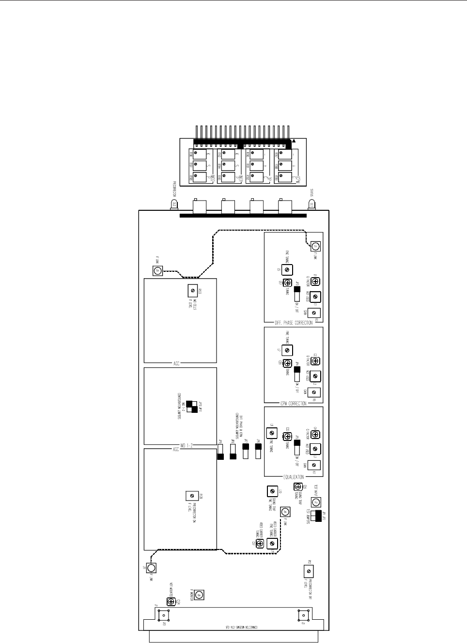
90
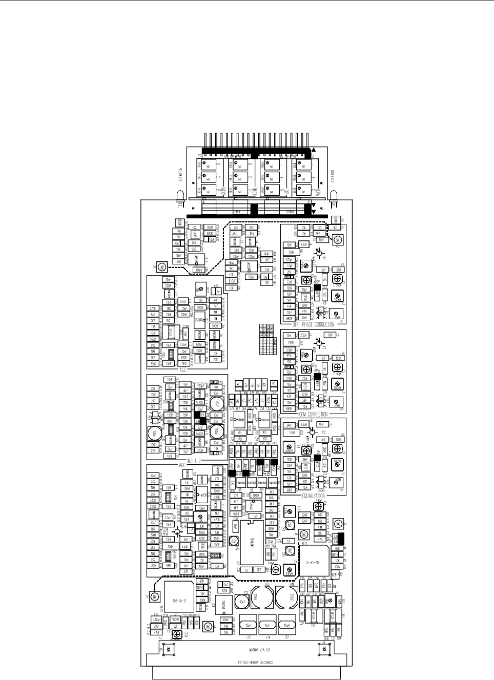
Component layout for adjustment points
91
The calibration procedure of the module requires a complete structure of display board (see MTG0079)
and extension module (see MTG0095) in order to perform the software selection which will be referred
to later and power the module itself. Besides a video modulator module (see MTG0072) and an audio
modulator module (see MTG0071/78) already calibrated are needed to calibrate, if neededm the
envelopment demodulator (only for the first calibration or to change the standard).
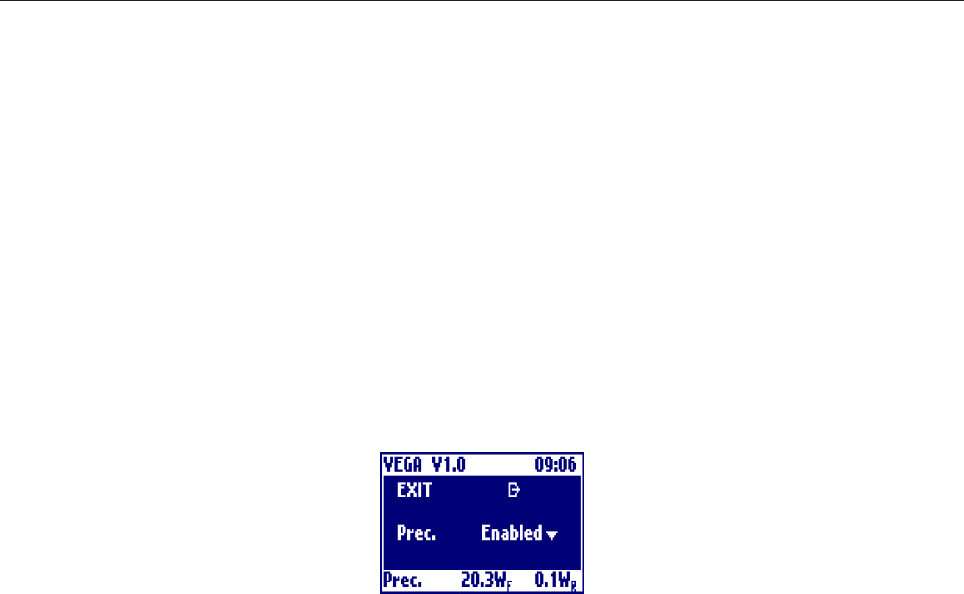
- Menu of the Multistandard IF Precorrector Module
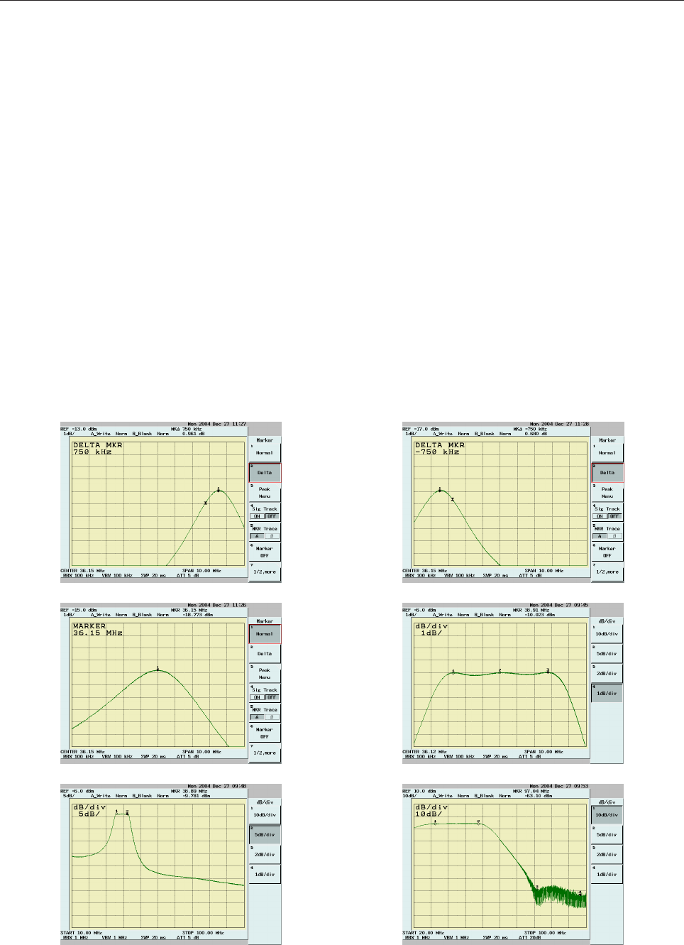
Verification of the ICPM and DP pre-correction section connect a spectrum analyser with tracking
between J2 and J1 and check the sections therein:
qCalibrate C20 and L7 to tune the cell of I.C.P.M. to the frequency of the video carrier summing about
750kHz (Fig.1) with JP4 on and JP3 and JP5 off.
qCalibrate C17 and L5 to tune the cell of D.P. to the frequency of the audio carrier subtracting about
750kHz (Fig.2) with JP3 on and JP4 and JP5 off.
qCalibrate C23, L9 to tune the equalisation cell to the middle of the intermediate frequency (Fig.3) with
JP5 on and JP3 and JP4 off.
qSet JP3, JP4 and JP5 on and check the response of the filter curve (Fig.4) to the desired passing band,
if needed retouch R3, R5 and R7 to correct the ripple in band and C1, C3 and C4 to equalise the group
delay of the filter obtaining a frequency response as in Fig.5.
Verification of the envelopment demodulator section connect the module to the frame provided with
video modulator by means of the extension board and check the sections therein:
qCalibrate C57 and L11 to obtain the best demodulation of the video signal by connecting an oscilloscope
to C44 (only if changing the IF standard).
qCalibrate C14 and L10 to obtain the best attenuation of the audio signal superimposed to the video signal
connecting an oscilloscope to C44 (only if changing the IF standard and with at least one audio module in
the frame).
Verification of the IMD1, 2 pre-correction sections connect a spectrum analyser with tracking between
J9 and J10 and check the sections therein:
92
Fig. 1 Fig. 2
Fig. 3 Fig. 4
Fig. 5 Fig. 6
qConfigure the module with Prec enabled.
qCalibrate R123 to an IF level of 0dBm on R178 and calibrate R126 to an IF level of -6dBm on J10 with
the tracking on -6dBm.
qCheck that the passing band of the section is similar as the one in Fig.6 and able to cover the whole IF
band from 30MHz to 50MHz.
Verification of the module without pre-correction connect a spectrum analyser with tracking between
J3 and J10 and check the sections therein:
qConfigure the module with Prec disabled.
qCalibrate R12 to an IF level of -6dBm on J10 with the tracking on -6dBm.
qCheck that the passing band of the section is flat within 0.2dB on the whole IF from 30MHz to 50MHz.
93
The testing procedure of the linearity pre-corrector is the consequence of a series of subsequent
interventions on the pre-corrector cells in order to achieve a good compromise of the video parameters
of the amplifier at the working power.
A calibration technique for the cells allowing to satisfy these requirements is proposed below; the
choice of the good compromise on the video parameters is anyway entrusted to the skill of the tester.
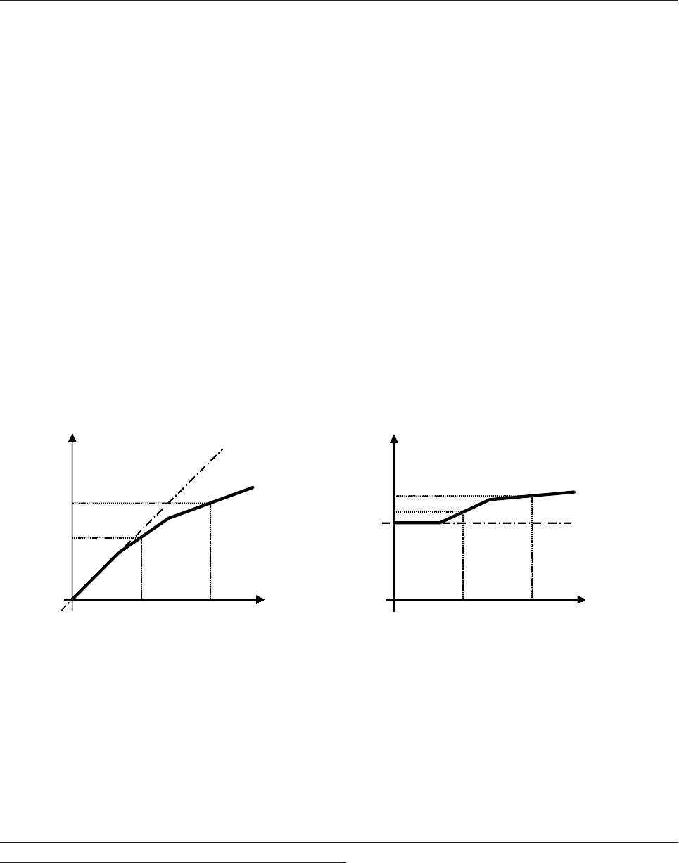
IMD1, 2 pre-correction - the intermodulation pre-correction inserts distortions in the negative Am modulation
linear characteristic of the video signal in order to compensate the distortions due to the power amplifier.
These are characterised by three parameters: Knee, Slope and Phase, and introduce some deviations from
the input/output linear characteristic of the pre-corrector.
For a more complete possibility of shaping the non-linearity characteristic, there are two pre-correction cells
in two particular regions of the characteristic: 50% APL (cell 1) and 100% APL (cell 2).
The suggested procedure to compensate the characteristic of the final power stage is to start positioning cell
1 (by acting on the K and S trimmers) in order to find a minimum point for the intermodulation, then position
cell 2; retouch the P trimmer if needed to refine the pre-correction.
Usually cell 1 only is needed to pre-correct A-class final stages, while for AB-class ones both cells are
needed.
In order to exclude one of the cells (or both at the beginning of the pre-correction procedure) it only takes
decreasing the K, S and P trimmers to the minimum.
Perform the pre-correction procedure for the intermodulation with the red bar video signal and repeat it for
the other colours if needed, refining the pre-correction.
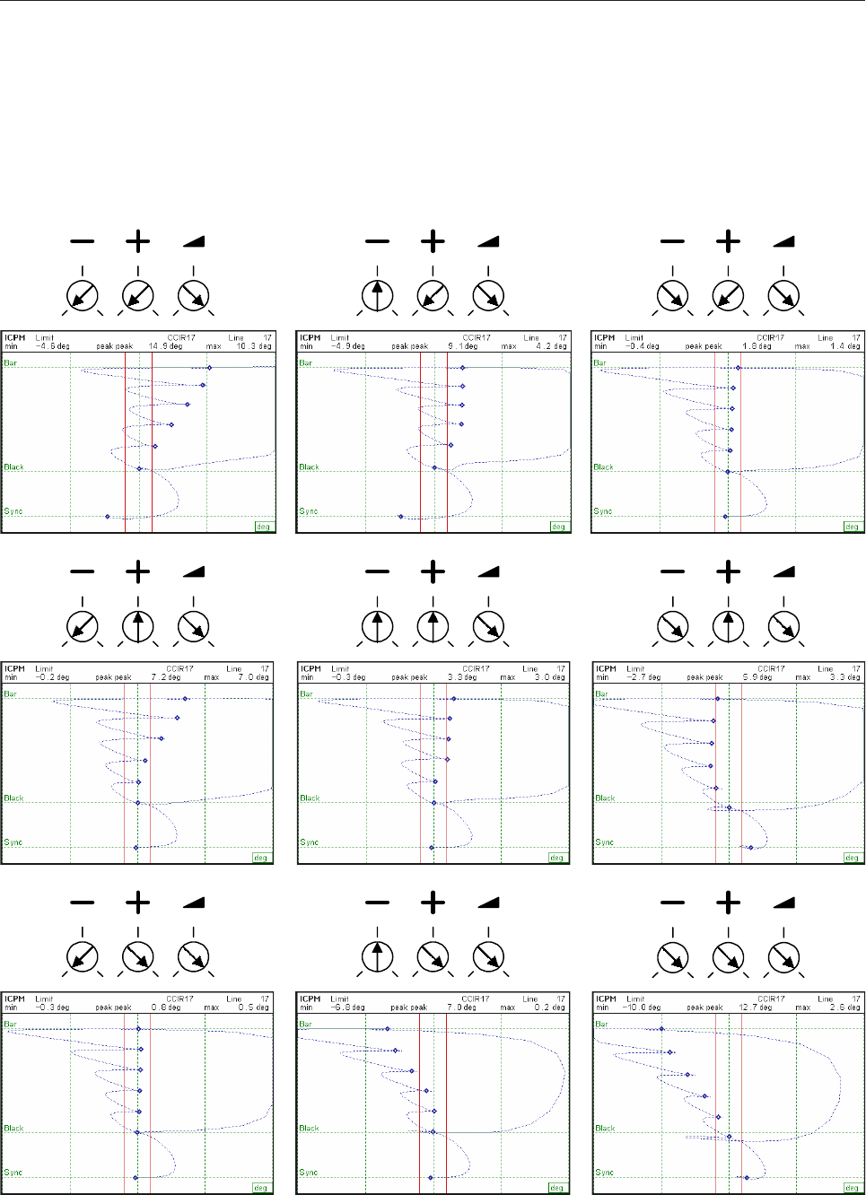
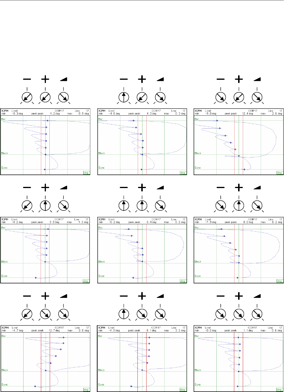
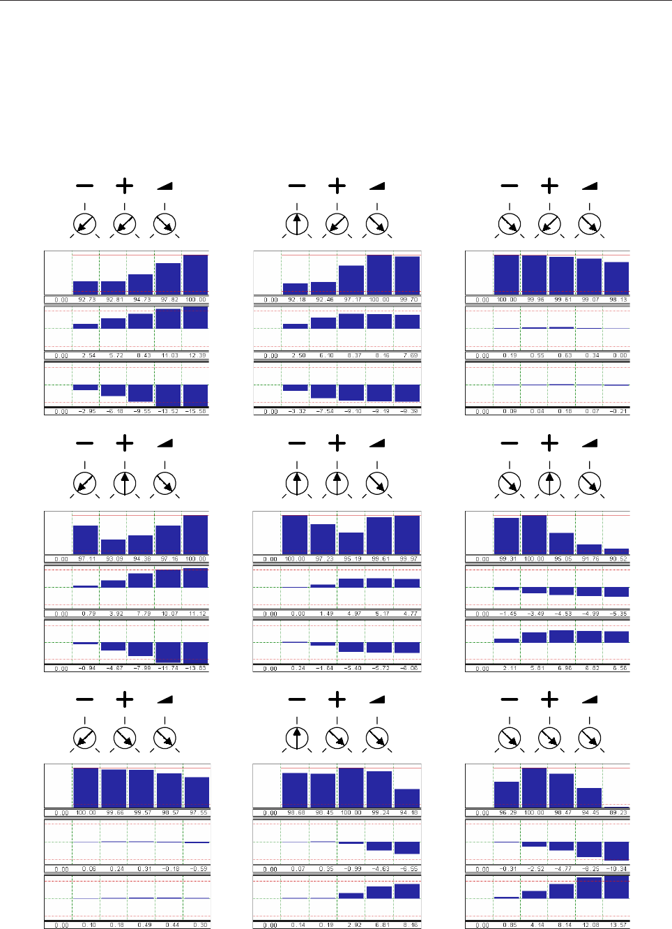
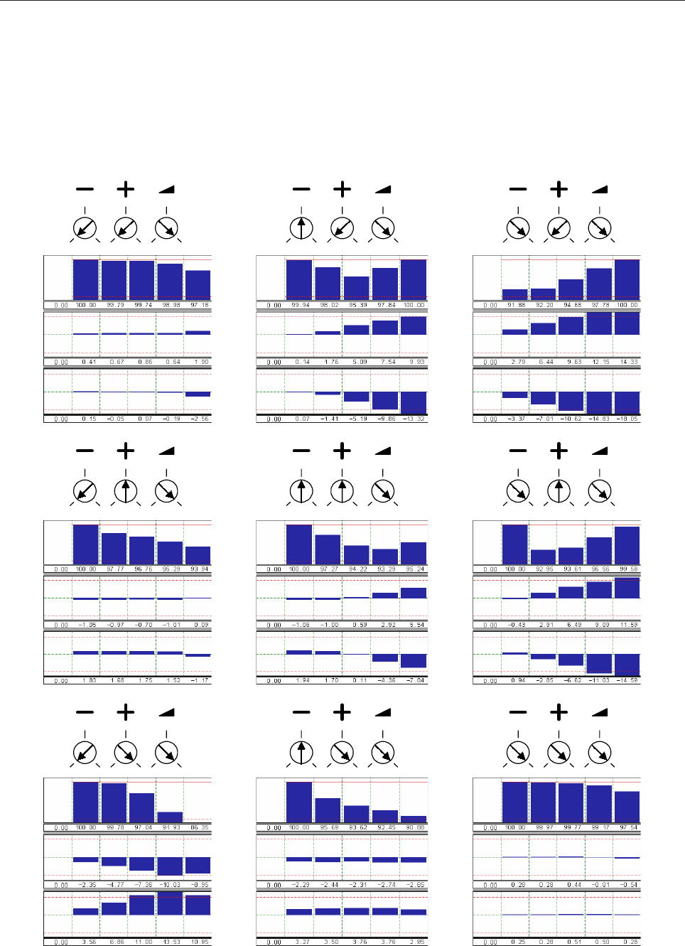
ICPM pre-correction a catalogue of the different kinds of pre-correction which can be introduced on the
ICPM parameter is given below. Once the measure has been taken, the situation which better approximates
50%APL 100%APL
IN
OUT
AM-AM
50%APL 100%APL
IN
OUT
AM-PM

94
the compensation has to be found, then the figure reproducing the measure in a specular way is to be
considered.
In the catalogue there are also the positions of the trimmers and the jumpers to obtain all proposed
configurations, of course intermediate solutions are possible and the intensity of all solutions may be scaled by
means of the level trimmer which is considered to be at the maximum intervention in the catalogue.
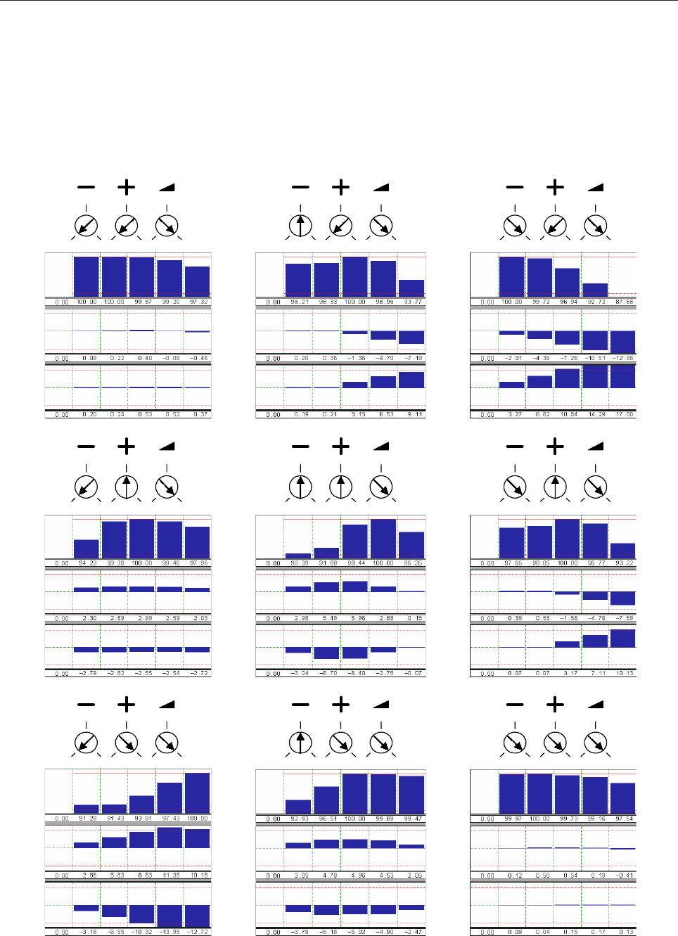
DP pre-correction a catalogue of the different kinds of pre-correction which can be introduced on the DP
parameter is given below. Once the measure has been taken, the situation which better approximates the
compensation has to be found, then the figure reproducing the measure in a specular way is to be considered.
In the catalogue there are also the positions of the trimmers and the jumpers to obtain all proposed
configurations, of course intermediate solutions are possible and the intensity of all solutions may be scaled by
means of the level trimmer which is considered to be at the maximum intervention in the catalogue.
95
- I.C.P.M. Pre-correction catalogue with: JP7 ®1-2; JP8 ® 1-2
96
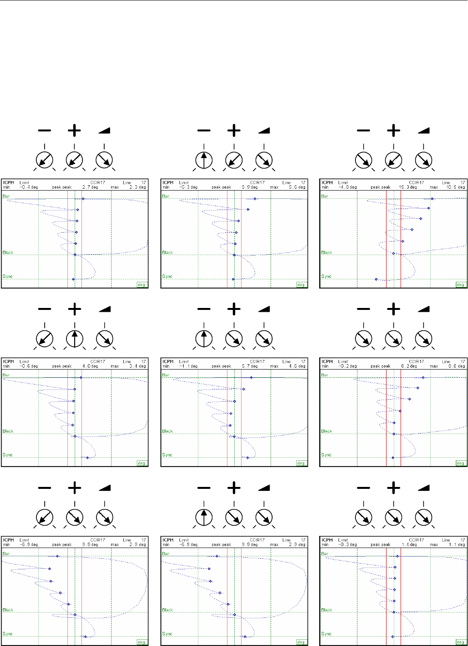
- I.C.P.M. Pre-correction catalogue with: JP7 ®2-3; JP8 ® 1-2
97
- I.C.P.M. Pre-correction catalogue with: JP7 ®1-2; JP8 ® 2-3
98
- D.P. Pre-correction catalogue with: JP6 ®1-2; JP9 ® 1-2
99
- D.P. Pre-correction catalogue with: JP6 ®2-3; JP9 ® 1-2
100
- D.P. Pre-correction catalogue with: JP6 ®1-2; JP9 ® 2-3
101
Component layout SCH0209AR1