Elettronika S r l TXUP500 500 Watt Analog TV Broadcast Transmitter User Manual APT159B AUTV 500LD Rev0 Date190105 p65
Elettronika S.r.l. 500 Watt Analog TV Broadcast Transmitter APT159B AUTV 500LD Rev0 Date190105 p65
Contents
Users manual Part 1

AUTV/500LD
LDMOS - UHF TV Solid State Amplifier
Users manual
CODE: APT159B TITLE: AUTV/500LD REV: 0 DATE: 19/01/05

SS 96 Km 113
70027 Palo del Colle (Ba) ITALY
Tel. +39 (0)80 626755
Fax +39 (0)80 629262
E-mail: elettronika@elettronika.it
Web site: http://www.elettronika.it
Registration number: IT-17686
Registration number: IT-24436

Index
Index ................................................................................................................................... 3
Warning .............................................................................................................................. 5
Warranty ............................................................................................................................. 6
Introduction ....................................................................................................................... 7
Content of the manual....................................................................................................... 7
Treatment of electrical shock ........................................................................................... 9
First-aid ......................................................................................................................... 10
Treatment of electrical burns .......................................................................................... 10
Note ............................................................................................................................... 10
Section 1 - Information .................................................................................................... 13
1.1 Description ............................................................................................................... 14
1.2 Technical characteristics.......................................................................................... 15
Section 2 - Installation ..................................................................................................... 17
2.1 Operating environment ............................................................................................ 18
2.2 Preliminary operations ............................................................................................. 18
2.3 Telemeasuring socket connections ......................................................................... 19
2.4 RS232, RS485 and AGC Socket connections ......................................................... 19
2.5 Preventive maintenance .......................................................................................... 20
Front panel .................................................................................................................... 21
Rear panel ..................................................................................................................... 22
Section 3 - Operation....................................................................................................... 23
3.1 Operation ................................................................................................................. 24
3.2 Display ..................................................................................................................... 25
3.3 Menu ........................................................................................................................ 25
- RF Powers ................................................................................................................ 27
- Power Supply ........................................................................................................... 27
- Log/Alarms ............................................................................................................... 27
- Working timer ........................................................................................................... 28
- Thresholds ............................................................................................................... 28
- RMS/Peak................................................................................................................ 29
- Date/Time ................................................................................................................ 29
- Display ..................................................................................................................... 29
- Frequency (only for FM Amplifiers) .......................................................................... 30
- Slave address .......................................................................................................... 30
- Remote .................................................................................................................... 30

- Interlock.................................................................................................................... 30
- Firmware release ......................................................................................................31
- Serial number .......................................................................................................... 31
Section 4 - Diagram ......................................................................................................... 33
Cable diagram ...............................................................................................................34
APT159A AUTV/500LD Power Supply Section ............................................................. 35
APT159A AUTV/500LDRF Section ............................................................................... 36
APT159A AUTV/500LD Lateral View ............................................................................ 37
MTF0083AR0 Amplifier module - Component list ........................................................ 38
APT159B AUTV/500LD - Component list ......................................................................... 39
SCH0192AR0 (200W UHF LDMOS Amplifier module) ................................................ 41
- Calibration procedure............................................................................................... 42
SCH0259AR0 (RF Amplifier interface) .......................................................................... 50
SCH0223AR1 (Control board and display) ................................................................... 52
- Description ............................................................................................................... 52
- Power Supply ........................................................................................................ 53
- Connectors ........................................................................................................... 53
- Firmware update.......................................................................................................58
SCH0288AR1 (Amplifier interface)................................................................................ 69
SCH0265AR0 (Mains distribution board) ...................................................................... 71
E0012 (SP500-27-DI Switching power supply) ............................................................... 73
06673 (UHF Bandpass filter CL3NL6 - 500W, 3 Sections + 2 Notches) ........................ 76

5
WARNING
The apparatus described in this manual has been designed and manufactured with devices to safe-
guard the users. In any case it is recommended that during any operation of installation, maintenance,
miscellaneous interventions and calibrations requiring the apparatus to be switched on,
THE USER TAKES ALL THE
PRECAUTIONS AGAINST INCIDENTS
It is required to use the proper clothes and protection gloves in order to prevent damages from inci-
dental contacts with high-voltage parts.
The manufacturer declines every responsibility in case the recommendations above are not followed.
IMPORTANT
The component lists attached to the relevant electrical diagrams indicate for each item the reference,
the description and the type normally used.
The Elettronika S.r.l. though reserves the right to use or supply as spare parts components with
equivalent characteristics but of a different type, assuring anyway the optimal work of the apparatus
in accordance with the specifications.
The enclosed monographs are solely owned by Elettronika S.r.l.
The use of anything enclosed in this technical manual without explicit authorization given by Elettronika
S.r.l. will be prosecuted by the law.
The data and technical characteristics of the apparatus described in this manual are not compelling for
the manufacturer.
The Elettronika S.r.l. reserves the right to make, without previous notice, modifications or updates in
order to improve the quality of the product.
The general conditions of supply and sale are described in the contracts.
The delivery time are in accordance with the products and quantities ordered.

6
Summary of warranty
We, ELETTRONIKA S.r.l., SS096 Km 113 Z.I. PALO DEL COLLE (BA) ITALY, warrant to the ORIGINAL PURCHASER of a NEW product, for a
period of one (1) year from the date of purchase by the original purchaser (the warranty period) that the new ELETTRONIKA product is free of defects
in materials and workmanship and will meet or exceed all advertised specifications for such a product. This warranty does not extend to any subsequent
purchaser or user, and automatically terminates upon sale or other disposition of our product.
Items excluded from this ELETTRONIKA warranty
We are not responsible for product failure caused by misuse, accident, or neglect. This warranty does not extend to any product on which the serial
number has been defaced, altered, or removed. It does not cover damage to loads or any other products or accessories resulting from ELETTRONIKA
product failure. It does not cover defects or damage caused by use of unauthorized modificstions, accessories, parts, or service.
What we will do
We will remedy any defect, in material or workmanship (except as excluded), in our sole discretion, by repair, replacement, or refund. If a refund is
elected, then you must make the defective or malfunctioning component available to us free and clear of all liens or other encumbrances. The refund will
be equal to the actual purchase price, not including interest, insurance, closing costs, and other finance charges less a reasonable depreciation on the
product from the date of original purchase. Warranty work can only be performed at our authorized service centers or at our factory. Expenses in
remedying the defect will be borne by ELETTRONIKA, including one-way surface freight shipping costs within the United States. (Purchaser must bear
the expense of shipping the product between any foreign country and the port of entry in the United States and all taxes, duties, and other customs fee(s)
for such foreign shipments).
How to obtain warranty service
You must notify us of your need for warranty service not later than ninety (90) days after the expiration of the warranty period. We will give you an
authorization to return the product for service. All components must be shipped in a factory pack or equivalent which, if needed, may
Desclaimer of consequential and incidental damages
You are not entitled to recover from us any consequential or incidental damages resulting from any defect in our product. This includes any damage
to another product or products resulting from such a defect.
Warranty alterations
No person has the authority to enlarge, or modify this warranty. The warranty is not extended by the lenght of time for which you are deprived of
the use of the product. Repairs and replacement parts are provided under the terms of this warranty shall carry only the unexpired portion of this
warranty.
Design changes
We reserve the right to change the design of any product from time to time without notice and with no obligation to make corresponding changes in
products previously manufactured.
Legal remedies of purchaser
There is no warranty which extends beyond the terms hereof. This written warranty is given in lieu of any oral or implied warranties not contained
herein. We disclaim all implied warranties, including without limitation any warranties of merchantability or fitness for a particular purpose. No action
to enforce this warranty shall be commenced later than ninety (90) days after expiration of the warranty period.
Warranty for electronic tubes
The warranty applied for electronic tubes is the one given by the manufacturer of the tube. In the event that the product shows anomalies within the
deadline of the validity of the warranty given by the manufacturer of the product itself, the buyer will have to return it to the seller with the needed
documents and the written description of the defect. The seller will ship the broken tube to the manufacturer in order to effect the necessary technical
tests to find out the cause of the anomaly. Meanwhile the buyer of the tube who needs to use, and as such to replace immediately the product, will have
to buy a new one and provide to the relevant payment, further to the issuing by the seller of a regular commercial invoice. After the adequate tests made
by the manufacturer, should the result be positive, that is confirm the defect in manufacturing, the seller will issue a regular credit note in the name of
the buyer and return the amount paid. Should the result be negative, that is detect a negligence in the installation or use by the buyer, he will have no
right against the seller.
Warranty

7
INTRODUCTION
The apparatus described in this manual is the latest of this series, offering high performances, remark-
able reliability and a wide range of characteristics, it all at a low cost.
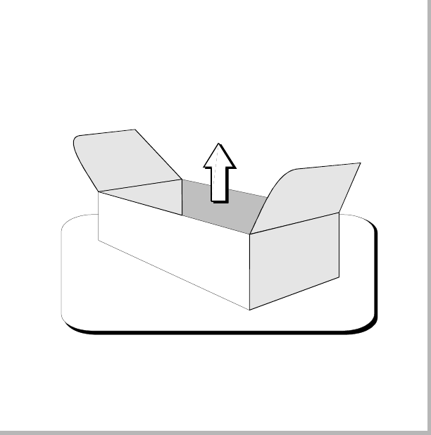
Its is easy to install and use. It only takes to follow the installation procedure as shown in this manual:
after having removed all from the package, you only have to follow step by step the description in the
various sections.
Before starting to use the apparatus, remember to:
read carefully the general safety information contained in this section;
follow the instructions for the installation and set up of the apparatus;
read all the remaining sections of this manual in order to know well the apparatus and learn
how to obtain the best of its characteristics.
CONTENTS OF THE MANUAL
The chapter composing this manual contain all the information concerning the use of the apparatus.
For more information refer to ELETTRONIKA S.r.l.
This manual is made up of different chapters, each made up of various sections. Each individual
chapter represents a single apparatus composing the whole station.

8
WARNING!
The currents and voltages in this equipment are dangerous!
Personnel must at all times observe safety regulation!
This manual is intended as a general guide for trained and qualified personnel who are aware of the
dangers inherent in handling potentially hazaedous electrical and electronic circuits.
It is not intended to contain a complete statement of all safety precautions which should be observed by
personnel in using this or other electronic equipment.
The installation, operation, maintenance and service of this equipment involves risks both to personnel
and equipment, and must be performed only by qualified personnel exercising due care.
Elettronika S.r.l. shall not be responsible for injury or damage resulting from improper procedures or
from the use of improperly trained or inexperienced personnel performing such tasks.
During installation and operation of this equipment, local building codes and fire protection standards
must be observed.
WARNING!
Always disconnect power before opening covers,
doors, enclosures, gates, panels or shields.
Always use grounding nsticks and short out high
voltage points before servicing. Never make
internal adjustments, perform maintenance or
service when alone or when fatigued.
Do not remove, short-circuit or tamper with interlock switches on access covers, doors, enclosures,
gates, panels or shields.
Keep away from live circuits, know your equipment and dont take chances.
WARNING!
In case of emergency ensure that power has been disconnected.
9
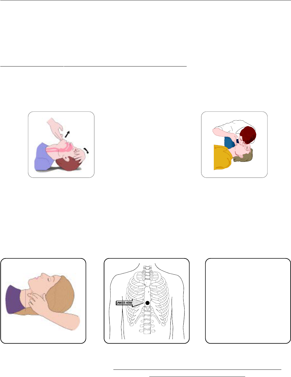
A - AIRWAY
If unconscious, open airway lift up neck, push
forehead back, clear out mouth if necessary,
observe for breathing.
Treatment of electrical shock
1) If victim is not responsive follow the A, B, Cs of basic life support.
PLACE VICTIM FLAT ON HIS BACK ON A HARD SURFACE
B - BREATHING
If not breathing, begin artificial breathing. Tilt
head, pinch nostrils, make airttght seal, 4 quick
full breaths. Remember mouth to mouth resuscita-
tion must be commenced as soon as possible.
C - CIRCULATION
Check carotid pulse. If pulse
absent, begin artificial circulation.
Approx. 80sec.: 1 rescuer, 15 compressions, 2 quick breaths.
Approx. 60sec.: 2 rescuers, 5 compressions, 1 breath.
NOTE: DO NOT INTERRUPT RHYTHM OF COMPRESSIONS WHEN
SECOND PERSON IS GIVING BREATH.
Call for medical assistance as soon as possible.

10
2) If victim is responsive:
- keep them warm;
- keep them as quiet as possible;
- loosen their clothing (a reclining position is recommended).
FIRST-AID
Personnel engaged in the installation, operation, maintenance or servicing of this equipment are urged
to become familiar with first-aid theory and practices. The following information is not intended to be
a complete first-aid procedure, it is brief and is only to be used as a reference. It is the duty of all
personnel using the equipment to be prepared to give adequate Emergency First Aid and thereby pre-
vent avoidable loss of life.
TREATMENT OF ELECTRICAL BURNS
1) Extensive burned and broken skin.
- Cover area with clean sheet or cloth (cleansed available cloth article);
- do not break blisters, remove tissure, remove adhered particles of clothing, or apply any salve or
ointment;
- treat victim for shock as required;
- arrange transportation to a hospital as quickly as possible;
- if arms or legs are effected keep them elevated.
NOTE
If medical help will not be available within an hour and the victim is conscious and not vomiting, give
him a weak solution of salt and soda: 1 level teaspoonful of salt and 1/2 level teaspoonful of baking
soda to each quart of water (neither hot or cold).
Allow victim to sip slowly about 4 ounces (half a glass) over a period of 15 minutes.
Discontinue fluid if vomiting occurs (do not give alcohol).
2) Less severe burns - (1st & 2nd degree).
- Apply cool (not ice cold) compresses using the cleansed available cloth article;
- do not break blisters, remove tissue, remove adhered particles of clothing, or apply salve or ointment;
- apply clean dry dressing if necessary;
- treat victim for shock as required;
- arrange transportation to a hospital as qickly as possible;
- if arms or legs are affected keep them elevated.
11
LDMOS - UHF TV AMPLIFIER
AUTV/500LD
Users manual

12
This page is intentionally blank

13
_______________________________________________________________________________________________
Section 1 - Information
Contents:
1.1 Description
1.2 Technical characteristics
14
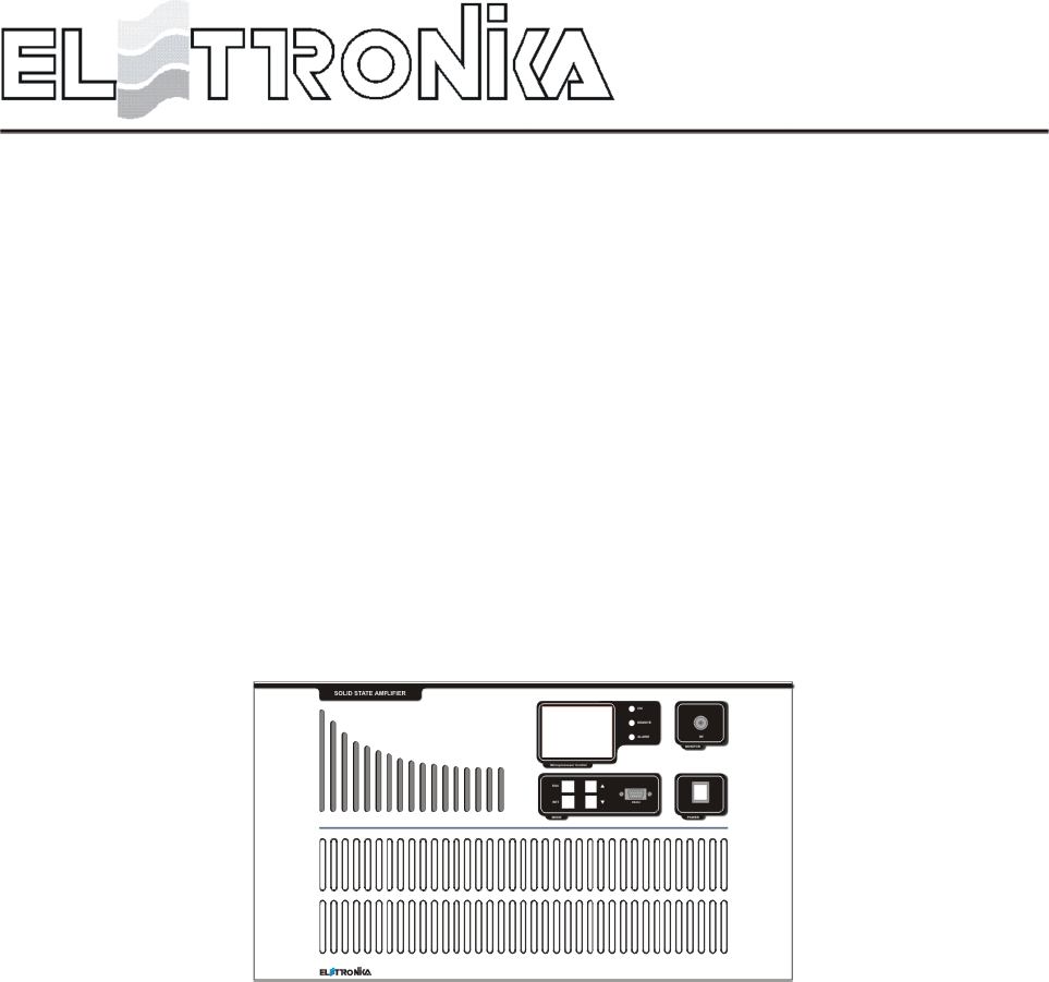
1.1 DESCRIPTION
The AUTV/500LD is an amplifier operating into Band IV-V for common amplification process of the Vision
and Sound carriers.
The amplifier has been designed to offer to the customer high performances, high reliability and greater simplicity
in his operation and maintenance procedures.
The amplifiers modules employ all solid state LDMOS technology in order to obtain high gain, wide-band
performances, very good linearity, reliability and high efficiency.
The equipment design allows the soft degradation (RF power loss) for several transistor faulty: in fact the
output combiner uses RF power resistors for unbalancing power dissipation. The unit is enclosed in a cabinet
for 19- 6U rackmounting.
AUTV/500LD
LDMOS - UHF TV AMPLIFIER

15
1.2 TECHNICAL CHARACTERISTICS
RF
Frequency range 470 - 860MHz
Output power 500W PEP
Video/Sound power ratio 10/1
Out stage technology Solid State LDMOS
Vision-Sound amplification Common
I.M.D. (-8, -10, -16dB) Better than -54dB
Standards G, K, N
Spurious and harmonics level In compliance with CCIR rec.
RF Output impedance 50W
RF Output connector 7/16
GENERAL
Power supply 230Vac, ±10%, 50/60Hz
400Vac 3P+N (on request)
Power consumption 1400VA at black level
RS232 Socket DB9 Connector (on front panel)
RS485 Socket DB9 Connector (on rear panel)
Telemeasuring socket DB9 Connector (on rear panel)
AGC Socket DB9 Connector (on rear panel)
Power factor > = 0.9
Ambient temperature -5° to +45°C
Relative humidity 20% - 90%
Altitude Up to 2.500 meters
Cooling Forced air
Cabinet Rack 19-6U
Weight 60kg
PROTECTION THR.
FWD Power 600W
REF Power 50W
Temperature 75°C
IDC 25A
VDC Min 10V - Max 33,5V

16
This page is intentionally blank
17
_______________________________________________________________________________________________
Section 2 - Installation
Contents:
2.1 Operating environment
2.2 Preliminary operations
2.3 Telemeasuring socket connections
2.4 RS232, RS485 and AGC socket connections
2.5 Preventive maintenance
- Front panel
- Rear panel
18
2.1 OPERATING ENVIRONMENT
You can install the apparatus in a standard component rack or on a suitable surface such as a bench or desk.
In any case, the area should be as clean and well-ventilated as possible. Always allow for at least 2 cm of
clearance under the unit for ventilation. If you set the apparatus on a flat surface, install spacers on the bottom
cover plate. If you install the apparatus in a rack, provide adequate clearance above and below. Do not locate
the apparatus directly above a hot piece of equipment.
2.2 PRELIMINARY OPERATIONS
Correct installation of the equipment is important for maximum performance and reliability. Antenna and earth
connections must be installed with the greatest care. The equipment adjustment isnt need, because the unit is
completely adjusted by our technical staff. This is the installation procedure:
1. connect the power supply cable of the exciter to the auxiliary socket on the rear panel of the amplifier;
2. connect the power supply cable of the amplifier to the electric network (230VAC). If there is the Isolator
Transformer, the amplifier is provided with cable and plug;
3. connect the exciter / antenna cables respectively to the RF IN and RF OUT on the rear panel of the
amplifier.
WARNING!!!
FOR ELECTRICAL SAFETY REASONS AND IN ORDER TO KEEP THE APPARATUS SAFE,
THE GROUND TERMINAL OF THE APPARATUS MUST BE CONNECTED TO THE EXISTING
GROUNDING SYSTEM AND NOT BY USING THE SHIELD OF THE OUTPUT COAXIAL CABLE.
1
3
Mono-Phase cabling
2
1 = L
2 = L
3 = N
4 = N
5 = GND
19
When the apparatus is put within a combined system it is directly connected to the input splitting and output
combining systems.
Before fully powering the apparatus, check that the output connections of the coaxial cable to the antenna
system are working.
In order to this it is possible to check the indication of the reflected power at low power levels. Only if the
SWR indication on the display is 0, the output power can be slowly increased. At maximum output power,
some watts might be shown as reflected power.
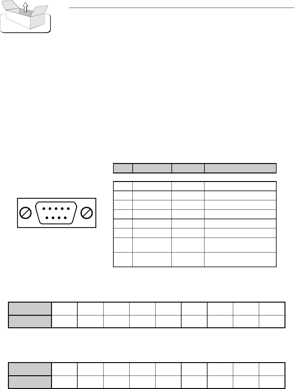
2.3 TELEMEASURING SOCKET CONNECTIONS
DB9 Socket
2.4 RS232, RS485 AND AGC SOCKET CONNECTIONS
PIN N° SIGNAL TYPE IN / OUT FUNCTION
1 Analog Output FWD Power
2 Analog Output REF Power
3 Digital Output Temperature
4 Digital Input Interlock
5GND - -
6 - 7 Digital Output Free contact (closed when alarm)
8 Digital Input 0V = ON
5V = Normal
9 Digital Input 0V = OFF
5V = Normal
PIN 123456789
FUNCTIONS -TxDRxD-GND----
RS232 - DB9 Socket
PIN 123456789
FUNCTIONS -Rx-Rx+5VGND-Tx-Tx+-
RS485 - DB9 Socket
20
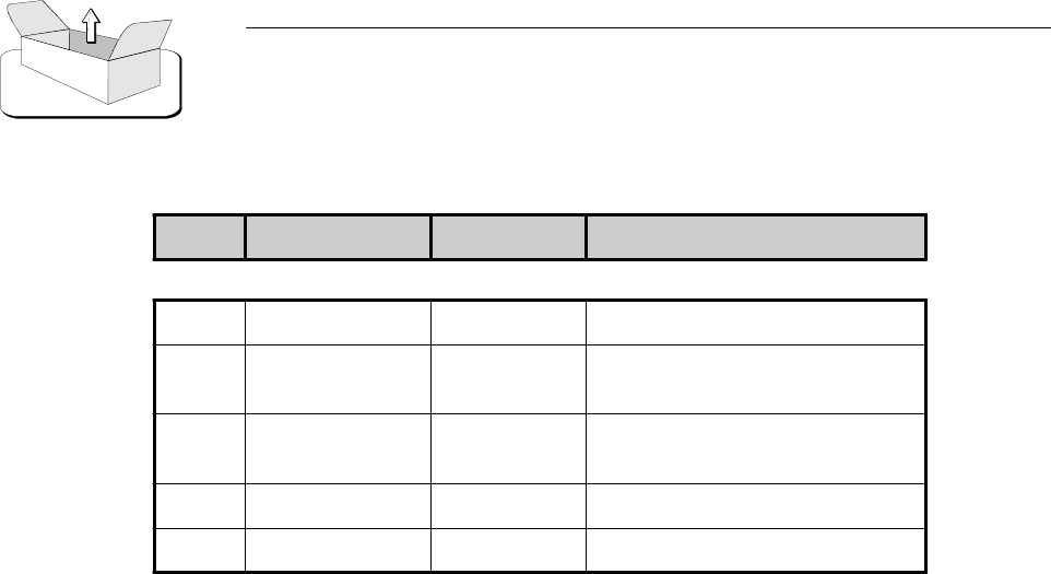
AGC - DB9 Socket
PIN N° SIGNAL TYPE IN / OUT FUNCTION
1GND - -
2 Digital Output 0V = Normal
5V = AGC Alarm
3 Digital Output 0V = Normal
5V = AGC Alarm
8 Analog Output FWD Power
9 Analog Output FWD Power
2.5 PREVENTIVE MAINTENANCE
To ensure maximum performance and minimum repair trouble, we strongly recommend you to follow the
below stated headlines for preventive maintenance:
1. check antenna installation and ground connection at regular intervals;
2. keep your apparatus clean and dry externally: this will ensure continuous functioning of the front panel
controls;
3. if the apparatus has not been used for a long period of time combined with exposure to extreme environ-
mental conditions, open the unit and make a visual inspection.
Remove salt, water or ice with a moist cloth before turning the apparatus on. Check that the cooling fans are
running freely.
4. for general maintenance and top performance, call an authorized service technician to give the apparatus
and the complete antenna/earth connection installation a general check every 12-18 months;
5. check at regular intervals that the air intake located on the front panel is free of dust. If there is visible dust,
remove it by means of a soft brush.
21
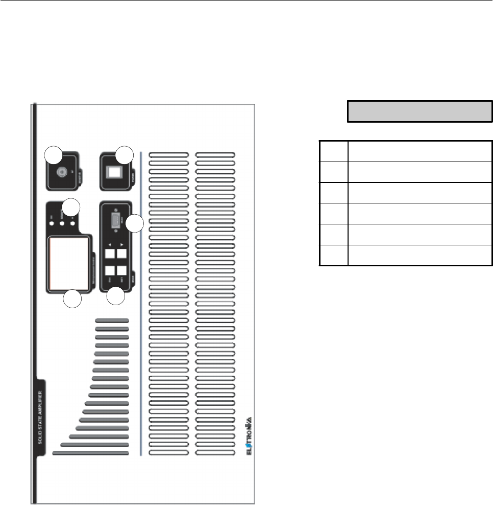
Front panel
1
2
3
4
5
6
DESCRIPTION
1LCD Display
2 Function keys
3 Status LEDs
4 RF Monitor connector
5 Main switch
6 RS232 Socket
22
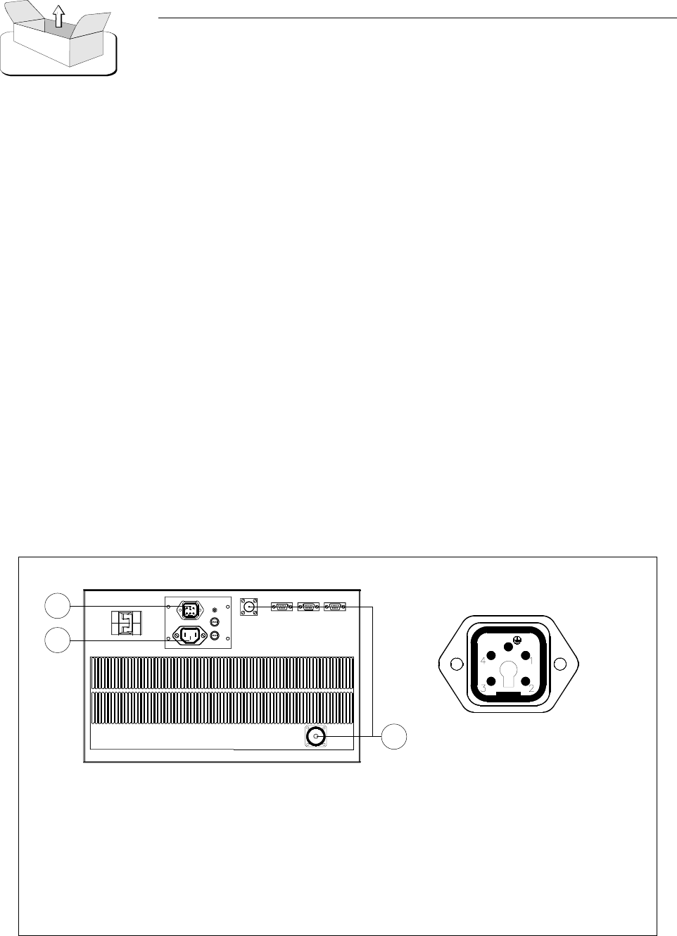
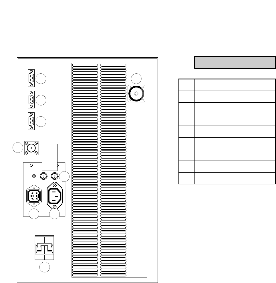
Rear panel
1
2
3
4
9
8
DESCRIPTION
1 Breaker
2 Power supply socket
3 Auxiliary socket
4Fuse
5 RS485 Socket
6 AGC Socket
7 Telemeasure socket
8 RF Input connector
9 RF Output connector
GND
DRIVER - 5A
CONTROL - 1A
5 6 7

23
_______________________________________________________________________________________________
Section 3 - Operation
Contents:
3.1 Operation
3.3 Display
3.4 Menu
24
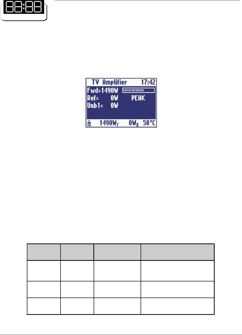
3.1 OPERATION
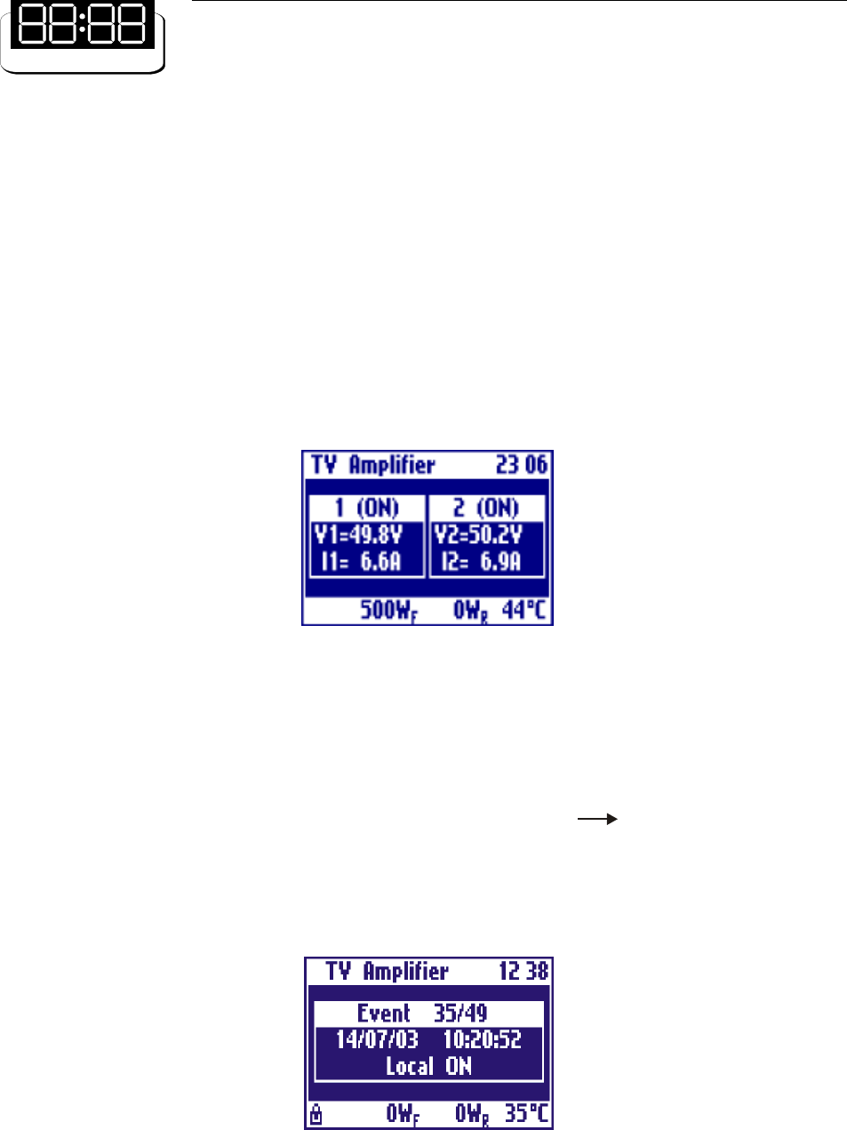
At startup, after initial image, the display shows the main screen with the RF powers as in Figure 1:
The user may turn on and off the amplifier by means of the switch on the front panel. The control board turns
on all the power supplies, the exciter (if any), and internal cooling fans. While the amplifier is working, the
micro-controller monitors continuously the most important parameters: power supply voltages, absorbed
currents, high power zone temperature, forward and reflected powers, unbalances (if any). Each measure is
associated to a maximum threshold beyond which the amplifier is immediately put in protection status by
turning off one or more power supply, depending on the failed block. In order to prevent a temporary problem
to trigger a definitive protection status, the failed block is turned on again, after some seconds, for up to five
times. If it goes beyond the protection threshold for more than five times, it is declared as FAILED and it will
no longer be turned on. In this case, the amplifier will have to be turned off manually by means of the switch on
the front panel, then turned on again after performing the needed maintenance.
On the front panel there are also three LEDs labelled ON, REMOTE and ALARM. Their meanings are
explained in Table 1.
Figure 1: Main screen
Table 1: Meanings of the three LEDs on the front panel
1 Screenshots in this manual are indicative, so they can be different from those on your equipment.
LED COLOUR MEANING MEANING WHEN BLINKING
ON Green The amplifier is on
The amplifier has been turned on
locally but it has been turned off by
remote
REMOTE Yellow Remote control is
enabled It never bli nks
ALARM Red An alarm is present It never blinks
25
3.2 DISPLAY
The control board is provided with a modern pixels graphic display with blue background. Normally it always
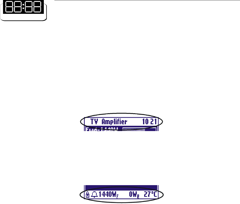
shows a title bar (on the top line) and a status bar (on the bottom line).
The title bar, see Figure 2, shows the name of the amplifier (TV Amplifier) and the current time. If the amplifier
is a single unit coupled externally with other units in a high power transmitter, the title bar shows the amplifier
number (slave address) too.
Figure 2: Title bar
Figure 3: Status Bar
The status bar (Figure 3) indicates the forward and reflected powers and the temperature. It also contains two
symbols for the interlock (lock) and the alarm (bell).
The bell symbol is continuously displayed in case of alarm. It blinks if there has been an alarm which has ended
but has not yet been seen by the user. It stops blinking once the Log has been checked.
The interlock symbol is displayed only when this function is enabled. It may be either a close lock, as in Figure
3, when there is no alarm (interlock chain closed) or an open lock in case of alarm (interlock chain open).
Since the status bar is always showed on the display, regardless of the screen, the user may monitor at any
time the most important parameters and the presence of alarms while moving between different screens.
3.3 MENUS
The user may see or modify locally some configuration parameters using the four buttons on the front panel.
All screens areorganized in a hierarchical menus and the user may move between them in a simple and intuitive
way.
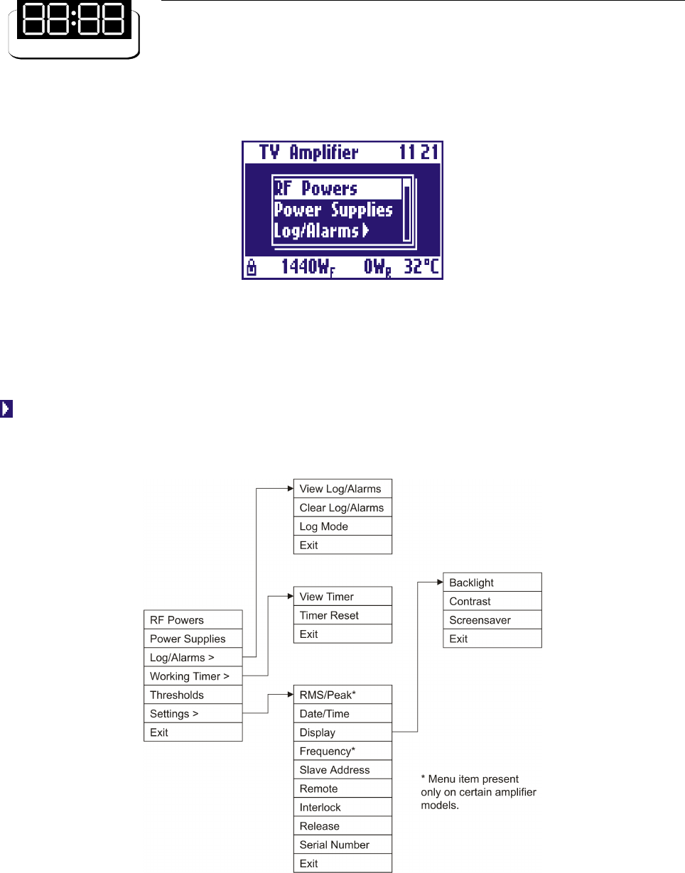
To see the menu its sufficient to press the ESC key (see Figure 4).
26
Figure 4: Main menu
The display only shows three items at a time: all the items can be scrolled by the UP and DOWN arrow keys.
Any item can be chosen by selecting it and pressing the RET key. Menu entries with an arrow on the right
open sub-menus when chosen. Thus there is a hierarchical structure as in Figure 5. To go back from a sub-
menu to the previous menu, press the ESC key. If the ESC key is pressed in the main menu, the RF powers
screen is accessed.
Figure 5: Hierarchical menu structure
All menu items are described in detail below.
27
- RF Powers
This is the main screen showing the RF powers of the amplifier: forward power, reflected power, unbalances,
if any. For forward power a level bar is displayed. See an example in Figure 1.
- Power Supply
This screen shows all the signals coming from two power supply. To check the next (previous) power supply
press the UP (DOWN) key. For each power supply, the voltage, the absorbed current and the status (ON or
OFF) are shown.
Figure 6: Power supply screen
- Log/Alarms
The control board is provided with an external EEPROM and a clock. Any alarm or switching event with the
time at which it occurred is saved in the EEPROM. The Log/Alarms sub-menu allows to manage this log.
It is possible to see the events stored in the log by selecting Log/Alarms View Log/Alarms. All events
can be scrolled by pressing the UP and DOWN keys. For example, the event shown in Figure 7 is the turning
on of the amplifier by means of the local switch. For every event/alarm a short description and the date and
time at which it occurred is displayed.
Figure 7: Event stored in the log
28
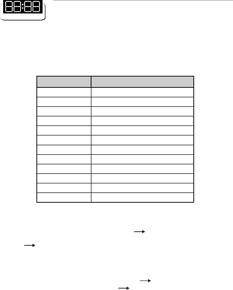
In case of alarm, the value of the measure which caused the alarm is saved into the log. In case of alarm still
existing after five turning-on attempts, the parameter is marked as FAILED. Table 2 is the list of all the events
which can be logged.
Table 2: Events managed and logged by the control board
The log may be completely deleted by selecting Log/Alarms Clear Log/Alarms.
Amplifier can store in the log details about alarms and generic events. You can change this behaviour selecting
Log/Alarms Log/Mode menu item.
- Working Timer
The control board has a working timer which is always enabled while the amplifier is working (i. e. there is at
least one power supply working). The menu entry Working Timer View Timer allows to check the hours
for which the timer has been enabled. Working Timer Timer Reset resets the timer.
- Thresholds
This is a screen showing the alarm threshold of each signals monitored by the control board. The list can be
scrolled by means of the UP and DOWN keys.
EVENT DESCRIPTION
Local ON Amplifier turned on by means of the local switch
Local OFF Amplifier turned off by means of the local switch
Remote ON Amplifier turned on remotely
Remote OFF Amplifier turned off remotely
Interlock open Interlock chain open
Interlock closed Interlock chain closed
Power Supply ON Power supply on
Fwd Pwr xxxxW Alarm for forward power
Ref Pwr xxxxW Alarm for reflected power
UnbY xxxxW Unbalancing alarm
V1 xx.xV Power supply voltage alarm
I1 xx.xA Power supply current alarm
29
- RMS/Peak
The control board can monitor both the RMS and peak powers, the first used in digital systems. The menu
entry Settings RMS/Peak allows to choose the power to be displayed and monitored. This menu is
present only in certain amplifiers.
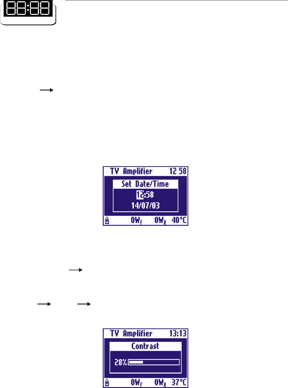
- Date/Time
This screen allows to set the current date and time. The setting is changed by pressing the arrow keys, then
pressing the RET key to move to the following value and eventually save the changes. To go back to the
previous menu and discard any change made, press the ESC key. Figure 8 shows an example of this screen.
Figure 8: Date and time setting screen
- Display
The menu entry Settings Display allows to change some settings of the display, such has back light,
contrast and screensaver. The back light and the contrast are set by means of the UP and DOWN arrow
keys. The changes made are saved by pressing the RET key or discarded pressing the ESC key. Figure 9
shows an example of this screen.
With Settings Display Screensaver you can set an interval time after which display backlight is
turned off. When display backlight is off, press any key to switch it on.
Figure 9: Display contrast setting screen
30
- Frequency (only for some Amplifiers)
The forward and reflected RF powers is measured by means of a directional coupler. In order to compensate
for the effect due to the sampling made by the coupler, it is possible to set the frequency by menu entry
Settings Frequency. The setting can be changed by pressing the arrow keys. The changes made are
saved by pressing the RET key or discarded pressing the ESC key. Set the video carrier frequency.
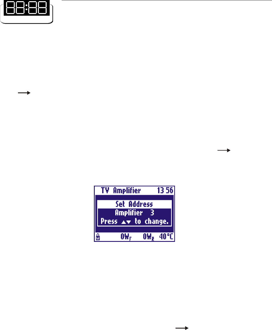
- Slave Address
The amplifier may be used either in stand-alone mode or as a slave of a master in a high power multiple units
transmitter. In the latter case an unique address for each amplifier has to be specified, in order for all of them
to communicate with the master on the same RS485 bus. The menu entry Settings Slave Address
allows to choose the stand-alone mode or set a slave address by means of the UP and DOWN arrow keys.
The changes made are saved by pressing the RET key or discarded pressing the ESC key. An example of this
screen is shown in Figure 10.
Figure 10:Slave address setting screen
- Remote
The amplifier may be controlled either locally, by means of the keys and display, or remotely. There are three
possibilities for remote control:
- using a direct serial connection between amplifier RS232 connector and a PC RS232;
- using the remote control device manufactured by Elettronika S.r.l. (RCU), on the RS485;
- using a general-purpose control system connected to telemeasures.
You can enable / disable remote control choosing menu item Settings Remote. When remote control
is enabled, the yellow REMOTE LED on the front panel is lit.
- Interlock
One of the pins of the telemeasure connector, located on the rear panel, is used for the interlock alarm. It is an
input line which turns off the amplifier in case of alarm. The interlock check can be enabled or disabled using

31
menu item Settings Interlock. When it is enabled, the status bar shows the lock symbol (see Figure 3),
which is close if the interlock chain is closed (no alarm) or open if it is open (alarm).
- Firmware Release
The menu entry Settings Firmware Release allows to display the firmware version number and the
hardware release of the amplifier.
- Serial Number
The menu entry Settings Serial Number allows to display the serial number of the apparatus.

32
This page is intentionally blank