Elettronika S r l TXUP500 500 Watt Analog TV Broadcast Transmitter User Manual APT139B VEGA Rev0 Date100604
Elettronika S.r.l. 500 Watt Analog TV Broadcast Transmitter APT139B VEGA Rev0 Date100604
Contents
- 1. Users manual Part 1
- 2. Users manual Part 2
- 3. Users manual Exciter part 1
- 4. Users manual Exciter Part 2
- 5. Users manual Exciter Part 3
Users manual Exciter part 1

VEGA
UHF - TV System
Users manual
CODE: APT139NM2 TITLE: VEGA REV: 0 DATE: 15/02/05

SS 96 Km 113
70027 Palo del Colle (Ba) ITALY
Tel. +39 (0)80 626755
Fax +39 (0)80 629262
E-mail: elettronika@elettronika.it
Web site: http://www.elettronika.it
Registration number: IT-17686
Registration number: IT-24436

Index
Index ................................................................................................................................... 3
Warning .............................................................................................................................. 5
Warranty ............................................................................................................................. 6
Introduction ....................................................................................................................... 7
Content of the manual....................................................................................................... 7
Treatment of electrical shock ........................................................................................... 9
First-aid ......................................................................................................................... 10
Treatment of electrical burns.......................................................................................... 10
Note ............................................................................................................................... 10
Section 1 - Information .................................................................................................... 13
1.1 Description............................................................................................................... 14
1.2 Main features ...........................................................................................................14
1.3 Technical characteristcs........................................................................................... 15
Front panel .................................................................................................................... 16
Rear panel ..................................................................................................................... 17
Section 2 - Installation ..................................................................................................... 19
2.1 Menu management ................................................................................................. 20
2.2 Menu description ..................................................................................................... 22
- Multistandard Audio Mono Section .......................................................................... 22
- Multistandard Audio Stereo Section (Option) ........................................................... 25
- Multistandard Video Section .................................................................................... 29
- Multistandard IF Precorrector Section ...................................................................... 31
- Multistandard Local Oscillator Section with Line Offset ............................................ 32
- Multistandard Local Oscillator Section with Field Offset (Option) ............................. 34
- Multistandard Channel Filter Section ....................................................................... 36
- Controller Module Section ....................................................................................... 39
- RF Amplifier Module Section ................................................................................... 43
- BUS Structure Section ............................................................................................. 45
- External Reference Section ..................................................................................... 46
2.3 Alarms and automation............................................................................................ 48
2.4 External AGC: Implementation and details .............................................................. 50
2.5 Power handling ........................................................................................................ 53
2.6 VEGA Factory setting............................................................................................... 54
- Setup Configuration ................................................................................................... 55
Section 3 - Diagram ......................................................................................................... 57

Cable diagram ...............................................................................................................58
APT139NM2 VEGA - Component list ............................................................................... 59
MTG0071AR1 (Multistandard Audio Mono Modulator Module) .................................... 60
MTG0078AR0 (Multistandard Audio Stereo Modulator Module) ................................... 67
MTG0072AR0 (Multistandard Video Modulator Module) .............................................. 76
MTG0073AR0 (Multistandard IF Precorrector Module) ................................................. 86
MTG0084AR0 (Multistandard UHF Local Oscillator Module) ..................................... 102
MTG0075AR0 (Multistandard UHF Channel Filter Module) ....................................... 108
MTG0079AR0 (Controller odule)................................................................................. 112
MTG0076AR0 (External Referement Module) ............................................................ 118
MTF0088BR0 (15W UHF Amplifier Module)............................................................... 122
SCH0194AR1 (BUS Structure).................................................................................... 130
E0017 (SP300-27 Switching power supply) ................................................................. 133

5
WARNING
The apparatus described in this manual has been designed and manufactured with devices to safe-
guard the users. In any case it is recommended that during any operation of installation, maintenance,
miscellaneous interventions and calibrations requiring the apparatus to be switched on,
THE USER TAKES ALL THE
PRECAUTIONS AGAINST INCIDENTS
It is required to use the proper clothes and protection gloves in order to prevent damages from inci-
dental contacts with high-voltage parts.
The manufacturer declines every responsibility in case the recommendations above are not followed.
IMPORTANT
The component lists attached to the relevant electrical diagrams indicate for each item the reference,
the description and the type normally used.
The Elettronika S.r.l. though reserves the right to use or supply as spare parts components with
equivalent characteristics but of a different type, assuring anyway the optimal work of the apparatus
in accordance with the specifications.
The enclosed monographs are solely owned by Elettronika S.r.l.
The use of anything enclosed in this technical manual without explicit authorization given by Elettronika
S.r.l. will be prosecuted by the law.
The data and technical characteristics of the apparatus described in this manual are not compelling for
the manufacturer.
The Elettronika S.r.l. reserves the right to make, without previous notice, modifications or updates in
order to improve the quality of the product.
The general conditions of supply and sale are described in the contracts.
The delivery time are in accordance with the products and quantities ordered.

6
Summary of warranty
We, ELETTRONIKA S.r.l., SS096 Km 113 Z.I. PALO DEL COLLE (BA) ITALY, warrant to the ORIGINAL PURCHASER of a NEW product, for a
period of one (1) year from the date of purchase by the original purchaser (the warranty period) that the new ELETTRONIKA product is free of defects
in materials and workmanship and will meet or exceed all advertised specifications for such a product. This warranty does not extend to any subsequent
purchaser or user, and automatically terminates upon sale or other disposition of our product.
Items excluded from this ELETTRONIKA warranty
We are not responsible for product failure caused by misuse, accident, or neglect. This warranty does not extend to any product on which the serial
number has been defaced, altered, or removed. It does not cover damage to loads or any other products or accessories resulting from ELETTRONIKA
product failure. It does not cover defects or damage caused by use of unauthorized modificstions, accessories, parts, or service.
What we will do
We will remedy any defect, in material or workmanship (except as excluded), in our sole discretion, by repair, replacement, or refund. If a refund is
elected, then you must make the defective or malfunctioning component available to us free and clear of all liens or other encumbrances. The refund will
be equal to the actual purchase price, not including interest, insurance, closing costs, and other finance charges less a reasonable depreciation on the
product from the date of original purchase. Warranty work can only be performed at our authorized service centers or at our factory. Expenses in
remedying the defect will be borne by ELETTRONIKA, including one-way surface freight shipping costs within the United States. (Purchaser must bear
the expense of shipping the product between any foreign country and the port of entry in the United States and all taxes, duties, and other customs fee(s)
for such foreign shipments).
How to obtain warranty service
You must notify us of your need for warranty service not later than ninety (90) days after the expiration of the warranty period. We will give you an
authorization to return the product for service. All components must be shipped in a factory pack or equivalent which, if needed, may
Desclaimer of consequential and incidental damages
You are not entitled to recover from us any consequential or incidental damages resulting from any defect in our product. This includes any damage
to another product or products resulting from such a defect.
Warranty alterations
No person has the authority to enlarge, or modify this warranty. The warranty is not extended by the lenght of time for which you are deprived of
the use of the product. Repairs and replacement parts are provided under the terms of this warranty shall carry only the unexpired portion of this
warranty.
Design changes
We reserve the right to change the design of any product from time to time without notice and with no obligation to make corresponding changes in
products previously manufactured.
Legal remedies of purchaser
There is no warranty which extends beyond the terms hereof. This written warranty is given in lieu of any oral or implied warranties not contained
herein. We disclaim all implied warranties, including without limitation any warranties of merchantability or fitness for a particular purpose. No action
to enforce this warranty shall be commenced later than ninety (90) days after expiration of the warranty period.
Warranty for electronic tubes
The warranty applied for electronic tubes is the one given by the manufacturer of the tube. In the event that the product shows anomalies within the
deadline of the validity of the warranty given by the manufacturer of the product itself, the buyer will have to return it to the seller with the needed
documents and the written description of the defect. The seller will ship the broken tube to the manufacturer in order to effect the necessary technical
tests to find out the cause of the anomaly. Meanwhile the buyer of the tube who needs to use, and as such to replace immediately the product, will have
to buy a new one and provide to the relevant payment, further to the issuing by the seller of a regular commercial invoice. After the adequate tests made
by the manufacturer, should the result be positive, that is confirm the defect in manufacturing, the seller will issue a regular credit note in the name of
the buyer and return the amount paid. Should the result be negative, that is detect a negligence in the installation or use by the buyer, he will have no
right against the seller.
Warranty

7
INTRODUCTION
The apparatus described in this manual is the latest of this series, offering high performances, remark-
able reliability and a wide range of characteristics, it all at a low cost.
Its is easy to install and use. It only takes to follow the installation procedure as shown in this manual:
after having removed all from the package, you only have to follow step by step the description in the
various sections.
Before starting to use the apparatus, remember to:
read carefully the general safety information contained in this section;
follow the instructions for the installation and set up of the apparatus;
read all the remaining sections of this manual in order to know well the apparatus and learn
how to obtain the best of its characteristics.
CONTENTS OF THE MANUAL
The chapter composing this manual contain all the information concerning the use of the apparatus.
For more information refer to ELETTRONIKA S.r.l.
This manual is made up of different chapters, each made up of various sections. Each individual
chapter represents a single apparatus composing the whole station.

8
WARNING!
The currents and voltages in this equipment are dangerous!
Personnel must at all times observe safety regulation!
This manual is intended as a general guide for trained and qualified personnel who are aware of the
dangers inherent in handling potentially hazaedous electrical and electronic circuits.
It is not intended to contain a complete statement of all safety precautions which should be observed by
personnel in using this or other electronic equipment.
The installation, operation, maintenance and service of this equipment involves risks both to personnel
and equipment, and must be performed only by qualified personnel exercising due care.
Elettronika S.r.l. shall not be responsible for injury or damage resulting from improper procedures or
from the use of improperly trained or inexperienced personnel performing such tasks.
During installation and operation of this equipment, local building codes and fire protection standards
must be observed.
WARNING!
Always disconnect power before opening covers,
doors, enclosures, gates, panels or shields.
Always use grounding nsticks and short out high
voltage points before servicing. Never make
internal adjustments, perform maintenance or
service when alone or when fatigued.
Do not remove, short-circuit or tamper with interlock switches on access covers, doors, enclosures,
gates, panels or shields.
Keep away from live circuits, know your equipment and dont take chances.
WARNING!
In case of emergency ensure that power has been disconnected.
9
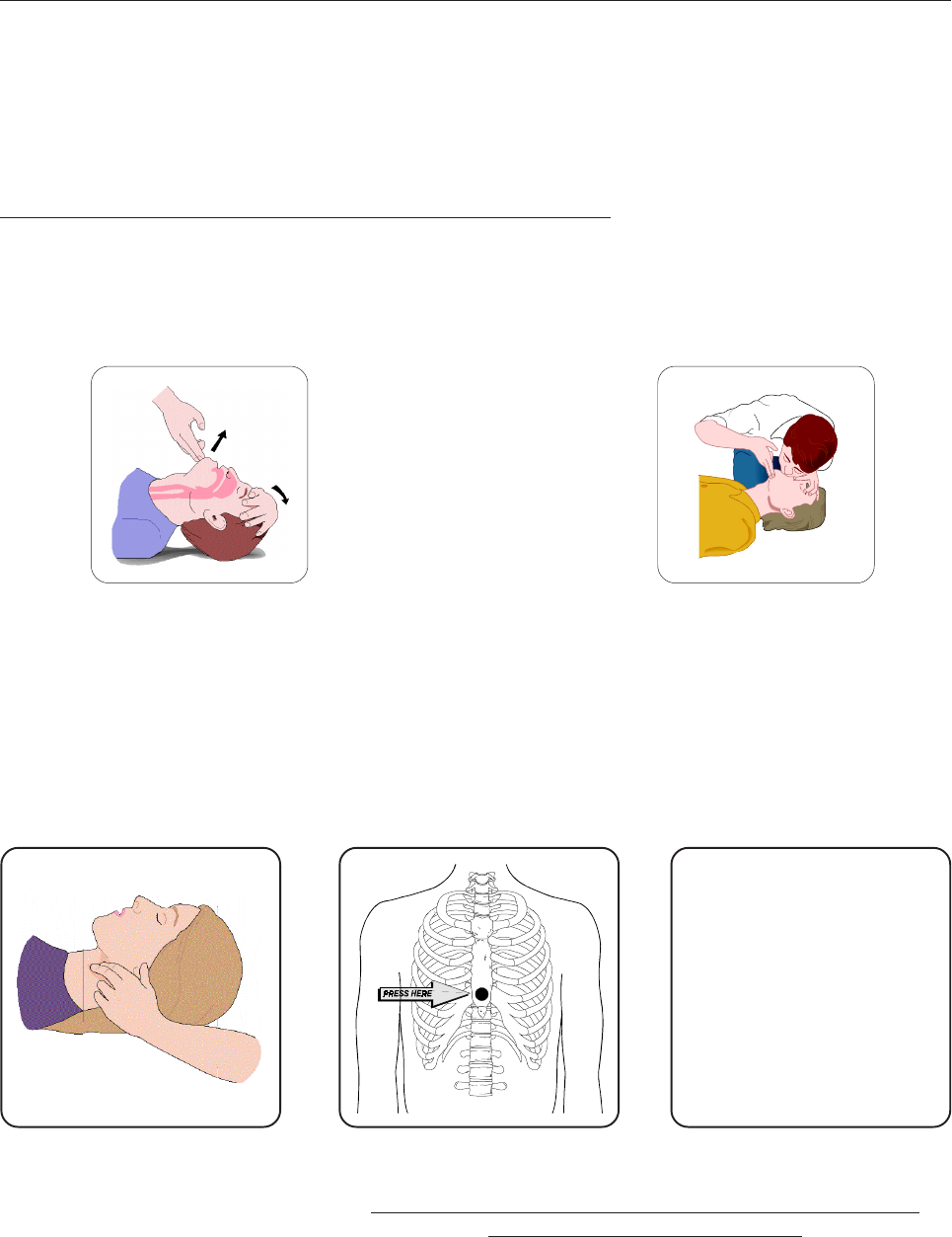
A - AIRWAY
If unconscious, open airway lift up neck, push
forehead back, clear out mouth if necessary,
observe for breathing.
Treatment of electrical shock
1) If victim is not responsive follow the A, B, Cs of basic life support.
PLACE VICTIM FLAT ON HIS BACK ON A HARD SURFACE
B - BREATHING
If not breathing, begin artificial breathing. Tilt
head, pinch nostrils, make airttght seal, 4 quick
full breaths. Remember mouth to mouth resuscita-
tion must be commenced as soon as possible.
C - CIRCULATION
Check carotid pulse. If pulse
absent, begin artificial circulation.
Approx. 80sec.: 1 rescuer, 15 compressions, 2 quick breaths.
Approx. 60sec.: 2 rescuers, 5 compressions, 1 breath.
NOTE: DO NOT INTERRUPT RHYTHM OF COMPRESSIONS WHEN
SECOND PERSON IS GIVING BREATH.
Call for medical assistance as soon as possible.

10
2) If victim is responsive:
- keep them warm;
- keep them as quiet as possible;
- loosen their clothing (a reclining position is recommended).
FIRST-AID
Personnel engaged in the installation, operation, maintenance or servicing of this equipment are urged
to become familiar with first-aid theory and practices. The following information is not intended to be
a complete first-aid procedure, it is brief and is only to be used as a reference. It is the duty of all
personnel using the equipment to be prepared to give adequate Emergency First Aid and thereby pre-
vent avoidable loss of life.
TREATMENT OF ELECTRICAL BURNS
1) Extensive burned and broken skin.
- Cover area with clean sheet or cloth (cleansed available cloth article);
- do not break blisters, remove tissure, remove adhered particles of clothing, or apply any salve or
ointment;
- treat victim for shock as required;
- arrange transportation to a hospital as quickly as possible;
- if arms or legs are effected keep them elevated.
NOTE
If medical help will not be available within an hour and the victim is conscious and not vomiting, give
him a weak solution of salt and soda: 1 level teaspoonful of salt and 1/2 level teaspoonful of baking
soda to each quart of water (neither hot or cold).
Allow victim to sip slowly about 4 ounces (half a glass) over a period of 15 minutes.
Discontinue fluid if vomiting occurs (do not give alcohol).
2) Less severe burns - (1st & 2nd degree).
- Apply cool (not ice cold) compresses using the cleansed available cloth article;
- do not break blisters, remove tissue, remove adhered particles of clothing, or apply salve or ointment;
- apply clean dry dressing if necessary;
- treat victim for shock as required;
- arrange transportation to a hospital as qickly as possible;
- if arms or legs are affected keep them elevated.
11
UHF - TV SYSTEM
VEGA
Users manual

12
This page is intentionally blank

13
_______________________________________________________________________________________________
Section 1 - Information
Contents:
1.1 Description
1.2 Main features
1.3 Technical characteristics
14
VEGA
UHF - TV SYSTEM
1.1 DESCRIPTION
The transmitters and transposers in this series VEGA are characterized by high performance and capability
and by excellent linearity over the entire band thanks to the optimization of the RF circuits.
A high degree of reliability is guaranteed, moreover, by the use of oversized cooling devices and by control
circuits operated by modern microprocessor technologies.
These units are used as low-power transmitters or transposers or as driver stages for amplifiers of greater
power and are available in 2 to 20W versions. The excellent spectral purity of the conversion oscillator
endows these units with an excellent signal/noise ratio of the radiated signal.
The synthesized local oscillator allows easy, rapid changing of the transmission channel from the front panel.
The offset option allows frequency shifts in 1Hz (CCIR) or 0.999000999Hz (FCC) steps for operation in
precision offset or isofrequency mode in the various television standards. The units are equipped with an
input connector for an external reference signal at 5MHz.
1.2 MAIN FEATURES
- Modular construction
- Programming of local oscillator from front panel
- SAW Vestigial filter
- Sync restore (SCT)
- Group delay precorrection (SCT)
- Automatic shite level and sync limiter (SCT)
- Multistandard modulator (SCT)
- Available in stero/dual sound version
- Possibility of use of common and separate carriers

15
1.3 TECHNICAL CHARACTERISTICS
VIDEO PARAMETERS
Input impedance 75W
Input level 1Vpp ±6dB
White / Sync level limiter 95%
2T K factor < 1.5%
Amplitude / frequency response ±0.5dB (throughout the vision band)
Differential gain < 5%
Differential phase < 3°
Group delay ±35ns (throughout the vision band)
Sync pulse compression < 3%
S/N ratio (weighted) > 60dB
Pre-emphasis 50ms or 75ms or flat
ICPM < 3°
Luminance non linearity < 4%
Field time bar tilt < 2%
Line time bar tilt < 2%
AUDIO PARAMETERS
Input impedance 600W or 10k, selectable
Input level 0dBm ±8dB, 0.5dB step
Frequency response (30Hz to 15kHz) ±0.5dB (±0.2 typ.)
T.H.D. (30Hz to 15kHz) < 0.4% (better then 0.2% typ.)
S/N ratio (unweighted) > 60dB
Pre-emphasis 50ms or flat
Stereo / Dual sound operation Available
Stereo Crosstalk > 37dB (better then 40dB typ.)
GENERAL
Ouput power 0 to 15W (Adj.)
Available standards B, D, G, H, I, K, M, N
Cooling Conventional
Operating temperature -10°C to +45°C
Maximum relative humidity 90%, non condensing
Mains power supply 90 to 260VAC
External reference frequency input 5MHz or 10MHz
Output impedance 50W
Output connector N Female
Dimensions 3U 19 Rackmount
Weight 15kg
Frequency stability 1ppm
I.M.D. at rated output power Better than -60dBc (-63dBc typical)
Harmonics -60dB or better
Sporious emissions -60dB or better
External interfaces Logic and analog signal outputs,
enable input, RS485, RS232
Specifications and characteristics are subject to change without notice.
16
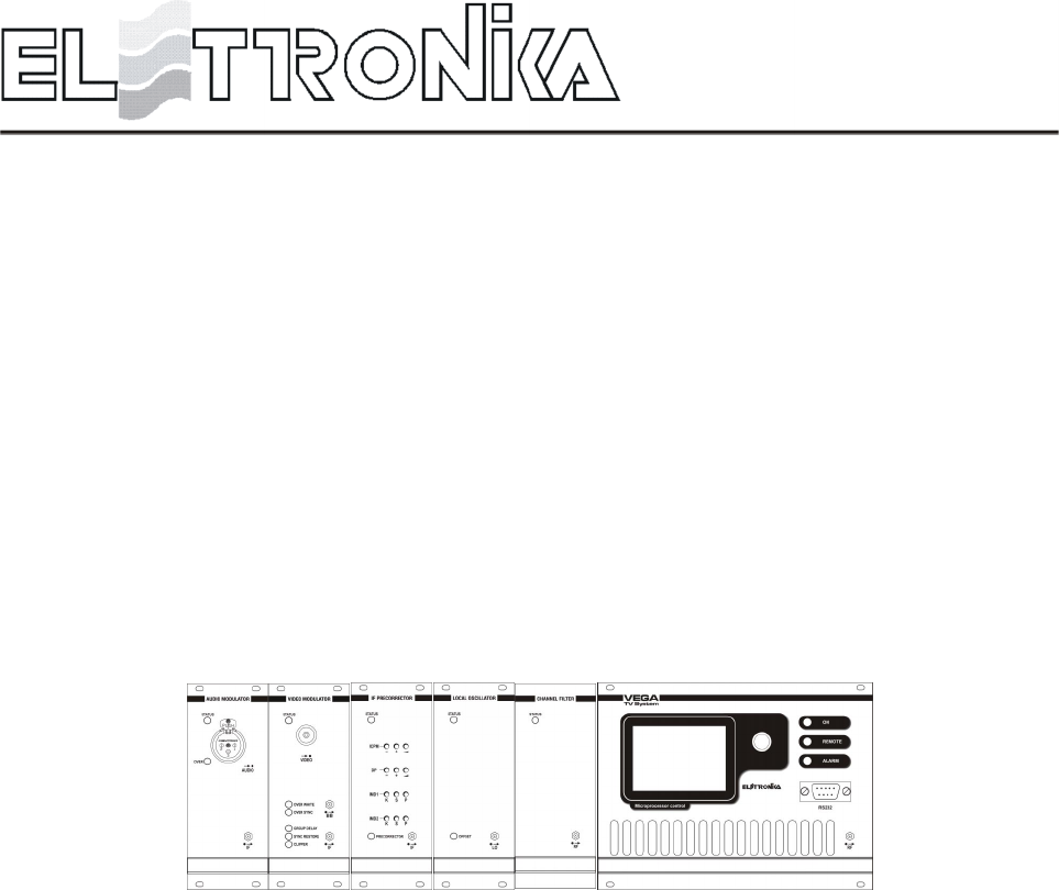
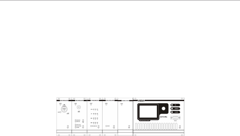
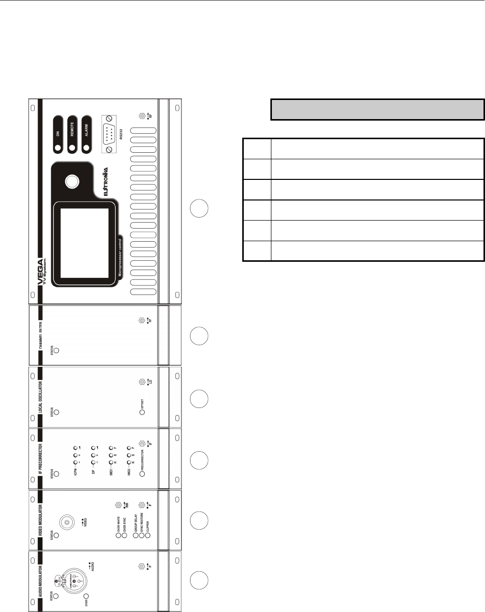
Front panel
1 2 53 4 6
DESCRIPTION
1 Mult. Mono Audio Modulator Module
2 Mult. Video Modulator Module
3 Mult. IF Precorrector Module
4 Mult. UHF Local Oscillator Module
5 Mult. UHF Channel Filter Module
6 Controller Module
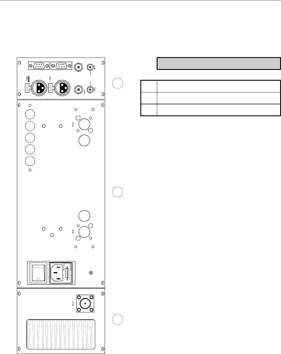
17
AUDIO2
TELEMEASURESRS485
VID EO 5M Hz I N/ OU T
IF LINK
RF RFRF
Rear panel
1 2 3
DESCRIPTION
1 RF Amplifier Module
2 Power Supply Module
3 External Referement Module

18
This page is intentionally blank

19
_______________________________________________________________________________________________
Section 2 - Operation
Contents:
2.1 Menu Management
2.2 Manu Description
2.3 Alarms and Automation

20
2.1 MENU MANAGEMENT
A large number of options of the VEGA TV exciter can be easily and intuitively controlled through the human-
to-machine interface on the right side of the VEGA. It is composed by a graphic display and a clickable knob.
When the VEGA is switched on it initialise itself and query to all attached boards on bus the release number.
During this period the display shows the screen below.
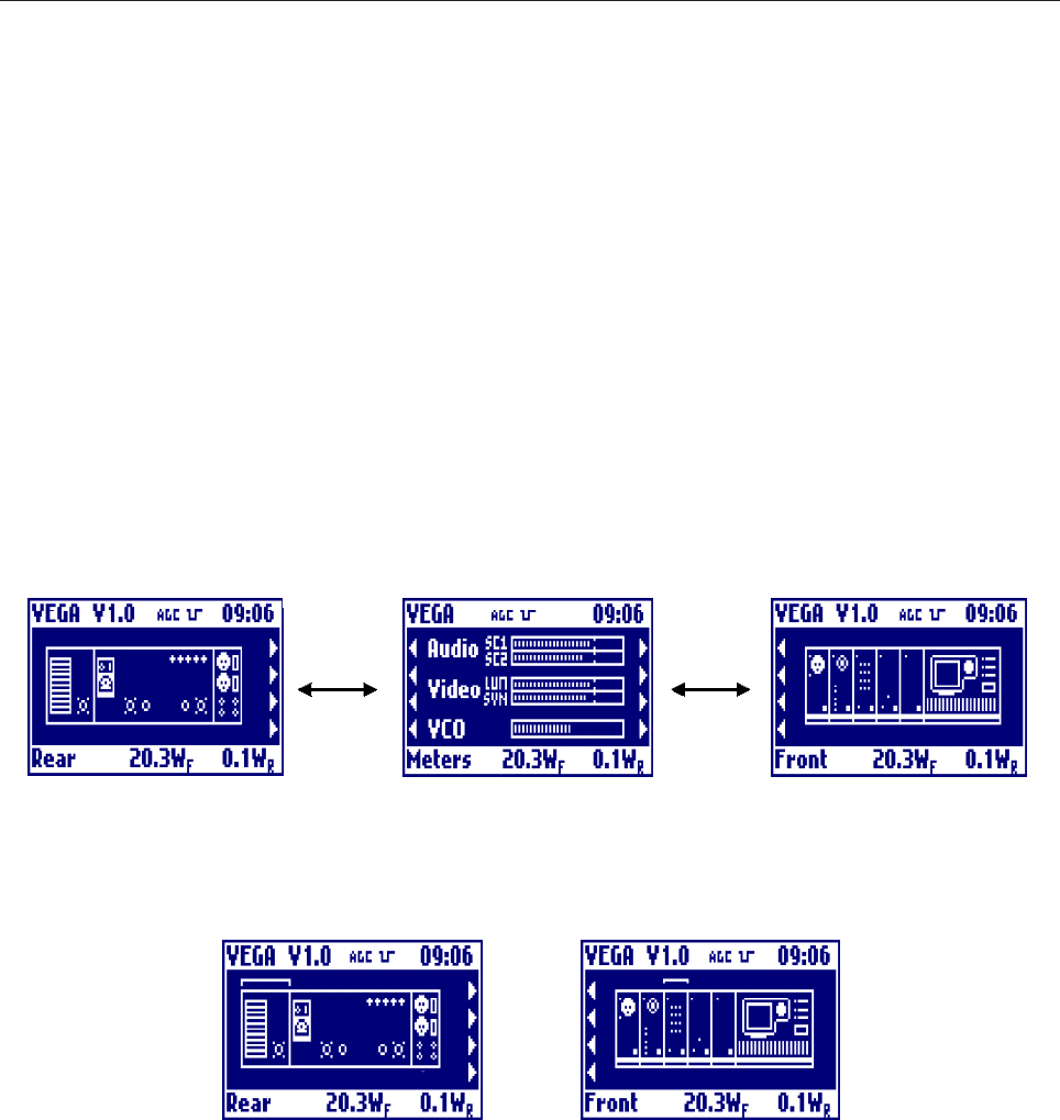
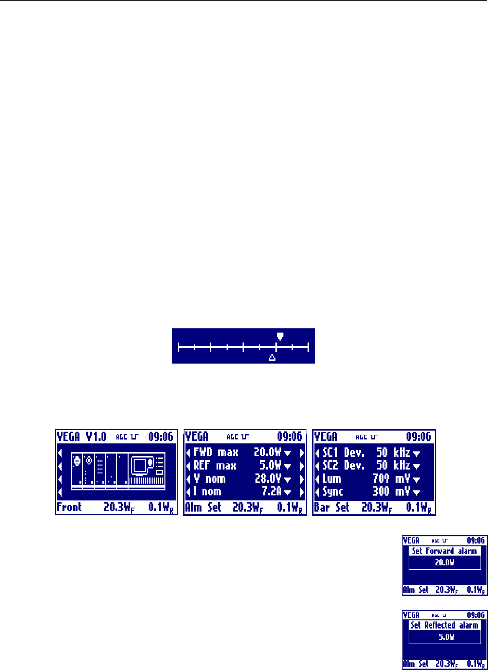
After the initialisation the VEGA goes to the main menu which contains the deviation bars of the audio IF
carrier signals and the White and Synch bar of the video signal. The last bar on the bottom is the one of the
VCO which shows the position of the control voltage of the local oscillator.
21
All of the menus of the VEGA contain a top bar which shows the name of the apparatus, the firmware version
of the display board and the current time, and a bottom bar showing the reading of the output forward and
reflected power and a summary of the current menu.
Since the number of menus of the VEGA is high, we give hereby a detailed description of all menus.
Note that the same firmware works either with the mono audio modulator and the stereo one. The firmware
only needs to be set to mono or stereo from the relevant menu. Depending on the selection, the look of some
menus may vary.
From the default menu, the bar meters menu, the user can navigate to other 2 menus. To navigate the menus,
rotate the knob. The presence of a menu on the left or the right of the current one is shown as arrows at the left
or the right respectively.
To enter the menu of the individual modules, select the module from the menu with the graphical image of
VEGA, both the rear and the front view. After clicking, a blinking arc will show in what module you can enter
clicking on the knob. To change module, rotate the knob.
Below are listed all the menus of all modules. Some symbols and functioning are always the same, and are:
l The EXIT menu is always on the first position of the leftmost menu and sends back to the default menu
containing the deviation bars. So to go back to the default menu you have always to go all menus left and click
2 times, the first for selection and the second for confirmation.
l The parameters may be represented in different ways depending on their type. In detail:
- the read-only parameters are represented by the name of the parameter and its current value. In case of
failure of a parameter, its value blinks;
- the parameter which can be set within a range of values are represented by the name of the parameter and
its set value, followed by an arrow pointing downward to show that the value is part of a list of possible
22
settings;
- the parameters which can be continuously set are represented by a bar showing the indication of the current
value (light) and of the one set at the factory (dark);
- Actions (e.g. "Clear History") are always followed by the ->|<- symbol. By selecting this voice and cofnirming,
the action will be executed.
l Pressing the knob while in any of the menus turns on a blinking cursor which can be used to select any
parameter simply by turning the control. Then the knob can be pressed again to open the window allowing to
change the selected parameter. In this window the control allows to choose the value, which has then to be
confirmed when requested.
2.2 MENU DESCRIPTION
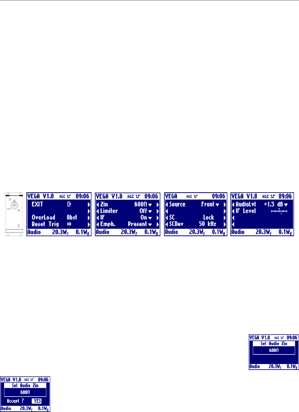
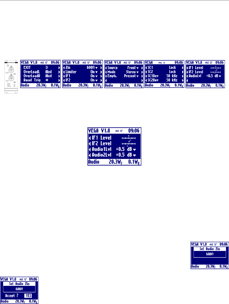
- Multistandard Audio Mono Section
EXIT
Clicking on the knob, after selecting this voice, goes back to the default menù.
Overload
Shows whether there is (Prst), there isnt (Abst) or there was (Trig) an overload of the audio signal. In
Absent and Triggered case, the label blinks.
Reset Trig
Clicking on the knob, after selecting this voice, delete the triggered indication from the overload.
Zin
Clicking on then knob, after selecting this voice, goes into the menu that allows to change
the impedance of the audio signal input connectors from 600Ohm to 10kOhm and back.
Rotate the knob to select the desired value and click on it.
Answer to the confirming question, selecting between accept or not. The answer starts
always from "Accept: NO", so to exit quickly form this menu simply click 2 times on the
knob.
23
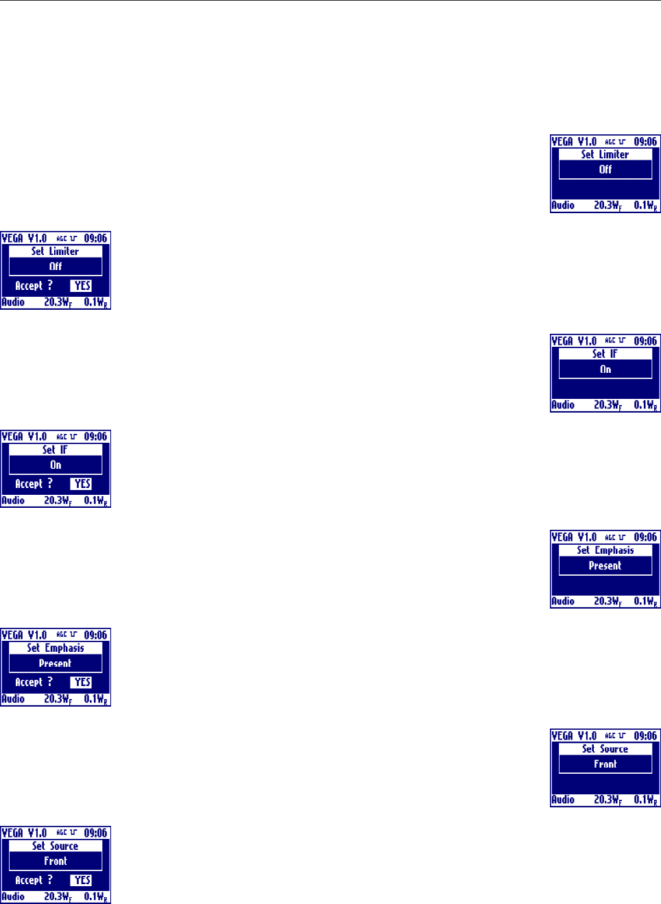
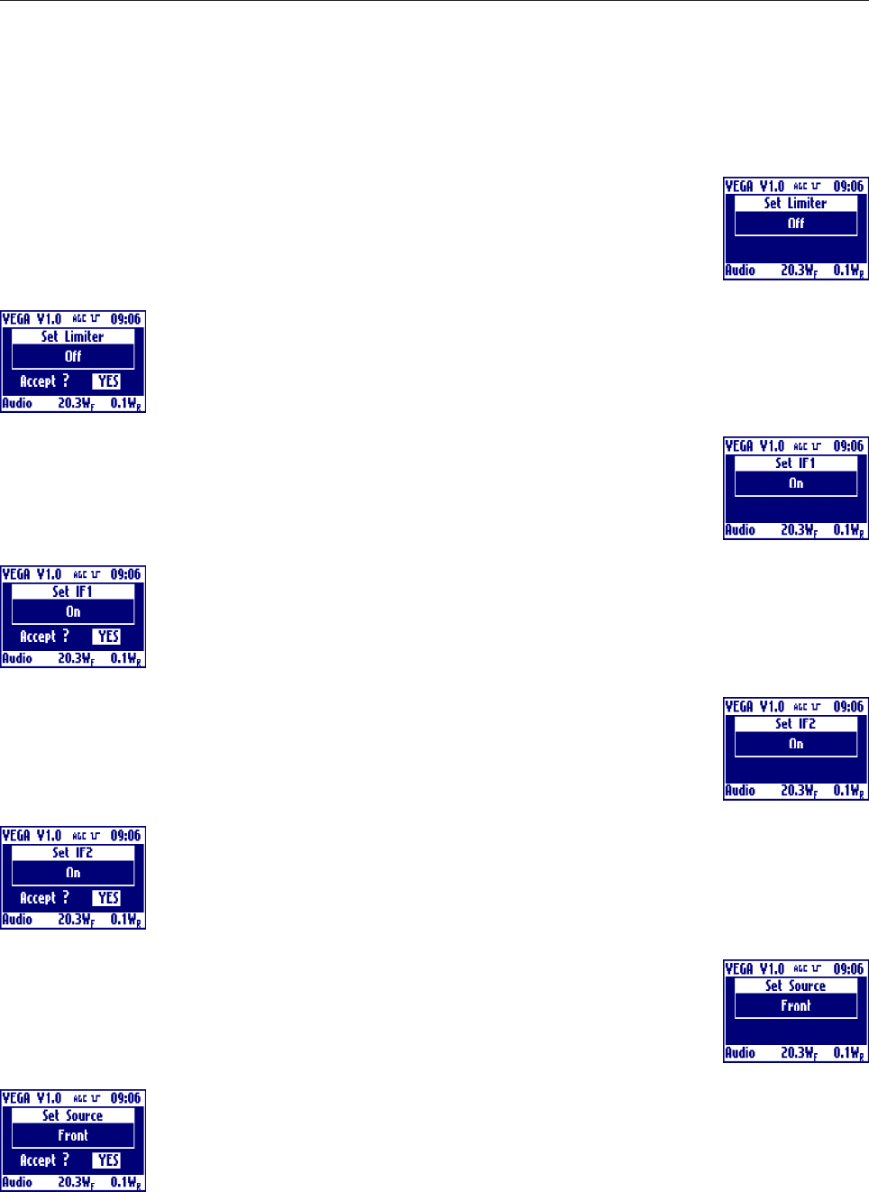
Limiter
Clicking on then knob, after selecting this voice, goes into the menu that allows to change
the Enables or Disables the limitation circuit. Rotate the knob to select the desired value
and click on it.
Answer to the confirming question, selecting between accept or not. The answer starts
always from "Accept: NO", so to exit quickly form this menu simply click 2 times on the
knob.
IF
Clicking on then knob, after selecting this voice, goes into the menu that allows to toggles
between on and off of the IF. Rotate the knob to select the desired value and click on it.
Answer to the confirming question, selecting between accept or not. The answer starts
always from "Accept: NO", so to exit quickly form this menu simply click 2 times on the
knob.
Emph.
Clicking on then knob, after selecting this voice, goes into the menu that allows to toggles
between presence and absence of the emphasis. Rotate the knob to select the desired
value and click on it.
Answer to the confirming question, selecting between accept or not. The answer starts
always from "Accept: NO", so to exit quickly form this menu simply click 2 times on the
knob.
Source
Clicking on then knob, after selecting this voice, goes into the menu that allows to choose
whether to sample the input signal from the front or rear panel. Rotate the knob to select
the desired value and click on it.
Answer to the confirming question, selecting between accept or not. The answer starts
always from "Accept: NO", so to exit quickly form this menu simply click 2 times on the
knob.
24
SC
Shows the PLL lock or unlock of the subcarrier. In case of unlock, the label blinks.
SCDev
Shows the Deviation in kHz of the subcarrier.
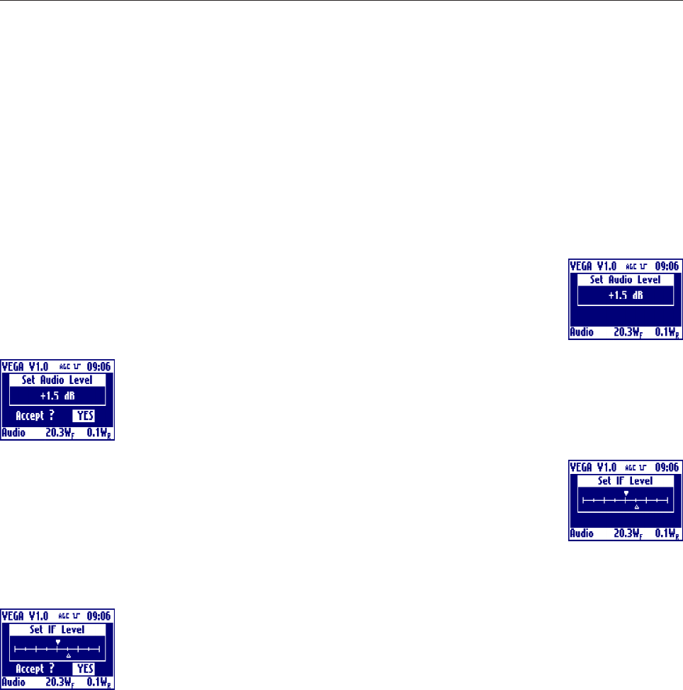
AudioLvl
Clicking on then knob, after selecting this voice, goes into the menu that allows to sets the
input audio signals level. Rotate the knob to select the desired value and click on it.
Answer to the confirming question, selecting between accept or not. The answer starts
always from "Accept: NO", so to exit quickly form this menu simply click 2 times on the
knob.
IF Level
Clicking on then knob, after selecting this voice, goes into the menu that allows to sets the
IF level. Rotate the knob to select the desired value and click on it.
The actual level is represented by the empty arrow, the full arrow represent the value of
the factory setting of this level. This 'factory default marker' can help you to set-up the exciter to a good value,
without ant instrumentation.
Answer to the confirming question, selecting between accept or not. The answer starts
always from "Accept: NO", so to exit quickly form this menu simply click 2 times on the
knob.
25
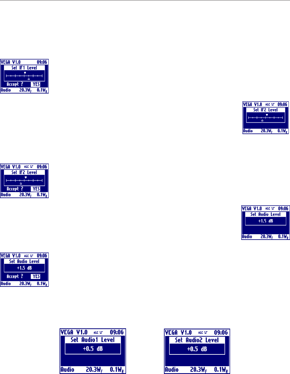
- Multistandard Audio Stereo Section (Option)
The last menu is showed as in stereo or mono mode settings. If the mode is set for a dual sound audio
modulation the last menu become the one below, because you can select to adjust the audio level to different
values.
EXIT
Clicking on the knob, after selecting this voice, goes back to the default menu.
OverloadL and OveroadR
Shows whether there is (Prst), there isn't (Abst) or there was (Trig) an overload of the audio left and right
signal. In Absent and Triggered case, the label blinks.
Reset Trig
Clicking on the knob, after selecting this voice, delete the triggered indication from the overload.
Zin
Clicking on then knob, after selecting this voice, goes into the menu that allows to change
the impedance of the audio signal input connectors from 600W to 10kW and back.
Rotate the knob to select the desired value and click on it.
Answer to the confirming question, selecting between accept or not. The answer starts
always from "Accept: NO", so to exit quickly form this menu simply click 2 times on the
knob.
26
Limiter
Clicking on then knob, after selecting this voice, goes into the menu that allows to change
the Enables or Disables the limitation circuit. Rotate the knob to select the desired value
and click on it.
Answer to the confirming question, selecting between accept or not. The answer starts
always from "Accept: NO", so to exit quickly form this menu simply click 2 times on the
knob.
IF1
Clicking on then knob, after selecting this voice, goes into the menu that allows to toggles
between on and off of the IF1. Rotate the knob to select the desired value and click on
it.
Answer to the confirming question, selecting between accept or not. The answer starts
always from "Accept: NO", so to exit quickly form this menu simply click 2 times on the
knob.
IF2
Clicking on then knob, after selecting this voice, goes into the menu that allows to toggles
between on and off of the IF2. Rotate the knob to select the desired value and click on
it.
Answer to the confirming question, selecting between accept or not. The answer starts
always from "Accept: NO", so to exit quickly form this menu simply click 2 times on the
knob.
Source
Clicking on then knob, after selecting this voice, goes into the menu that allows to choose
whether to sample the input signal from the front or rear panel. Rotate the knob to select
the desired value and click on it.
Answer to the confirming question, selecting between accept or not. The answer starts
always from "Accept: NO", so to exit quickly form this menu simply click 2 times on the
knob.
27
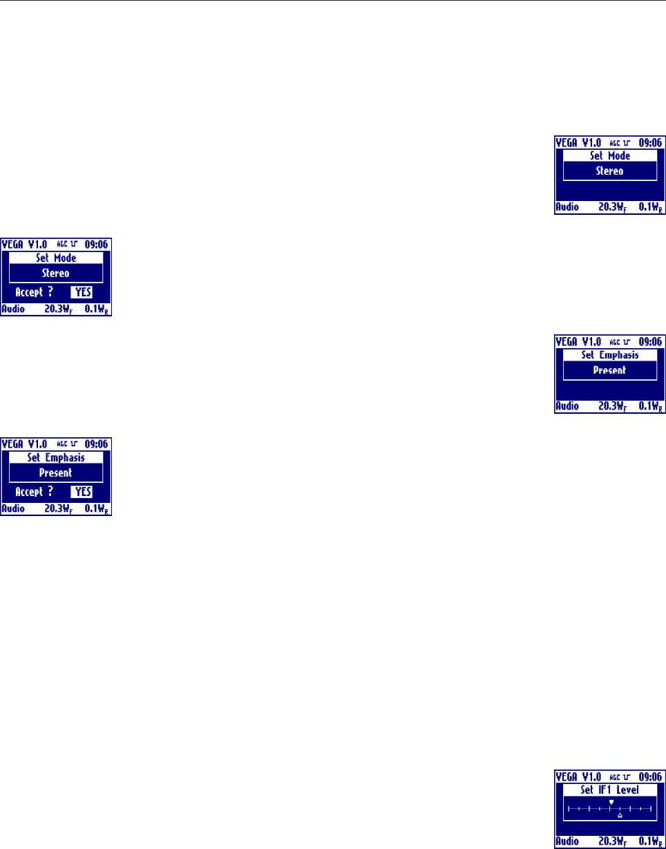
Mode
Clicking on then knob, after selecting this voice, goes into the menu that allows to choose
the operating mode between mono, stereo or dual sound. Rotate the knob to select the
desired value and click on it.
Answer to the confirming question, selecting between accept or not. The answer starts
always from "Accept: NO", so to exit quickly form this menu simply click 2 times on the
knob.
Emph.
Clicking on then knob, after selecting this voice, goes into the menu that allows to toggles
between presence and absence of the emphasis. Rotate the knob to select the desired
value and click on it.
Answer to the confirming question, selecting between accept or not. The answer starts
always from "Accept: NO", so to exit quickly form this menu simply click 2 times on the
knob.
SC1
Shows the PLL lock or unlock of the subcarrier 1. In case of unlock, the label blinks.
SC2
Shows the PLL lock or unlock of the subcarrier 2. In case of unlock, the label blinks.
SC1Dev
Shows the Deviation in kHz of the subcarrier 1.
SC2Dev
Shows the Deviation in kHz of the subcarrier 2.
IF1 Level
Clicking on then knob, after selecting this voice, goes into the menu that allows to sets the
IF1 level. Rotate the knob to select the desired value and click on it. The actual level is
represented by the empty arrow, the full arrow represent the value of the factory setting
of this level. This 'factory default marker' can help you to set-up the exciter to a good
value, without ant instrumentation.
28
Answer to the confirming question, selecting between accept or not. The answer starts
always from "Accept: NO", so to exit quickly form this menu simply click 2 times on the
knob.
IF2 Level
Clicking on then knob, after selecting this voice, goes into the menu that allows to sets the
IF2 level. Rotate the knob to select the desired value and click on it. The actual level is
represented by the empty arrow, the full arrow represent the value of the factory setting
of this level. This 'factory default marker' can help you to set-up the exciter to a good value, without ant
instrumentation.
Answer to the confirming question, selecting between accept or not. The answer starts
always from "Accept: NO", so to exit quickly form this menu simply click 2 times on the
knob.
AudioLvl
Clicking on then knob, after selecting this voice, goes into the menu that allows to sets the
input audio signals level. Rotate the knob to select the desired value and click on it.
Answer to the confirming question, selecting between accept or not. The answer starts
always from "Accept: NO", so to exit quickly form this menu simply click 2 times on the
knob.
If the mode is set for a dual sound audio modulation you can select to adjust the audio level to different values,
so the set audio level menu become two different menus for audio1 and audio2 level setting as showed below:
29
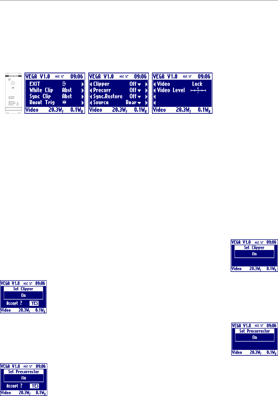
- Multistandard Video Section
EXIT
Clicking on the knob, after selecting this voice, goes back to the default menu.
White Clip
Shows whether there is (Prst), there isn't (Abst) or there was (Trig) the clipper intervention on white. In
Absent and Triggered case, the label blinks.
Sync Clip
Shows whether there is (Prst), there isn't (Abst) or there was (Trig) the clipper intervention on sync. In Absent
and Triggered case, the label blinks.
Reset Trig
Clicking on the knob, after selecting this voice, delete the triggered indication from the clippers.
Clipper
Clicking on then knob, after selecting this voice, goes into the menu that allows to toggle
the clipper intervention. Rotate the knob to select the desired value and click on it.
Answer to the confirming question, selecting between accept or not. The answer starts
always from "Accept: NO", so to exit quickly form this menu simply click 2 times on the
knob.
Precorr
Clicking on then knob, after selecting this voice, goes into the menu that allows to toggle
the group delay pre-corrector. Rotate the knob to select the desired value and click on it.
Answer to the confirming question, selecting between accept or not. The answer starts
always from "Accept: NO", so to exit quickly form this menu simply click 2 times on the
knob.
30
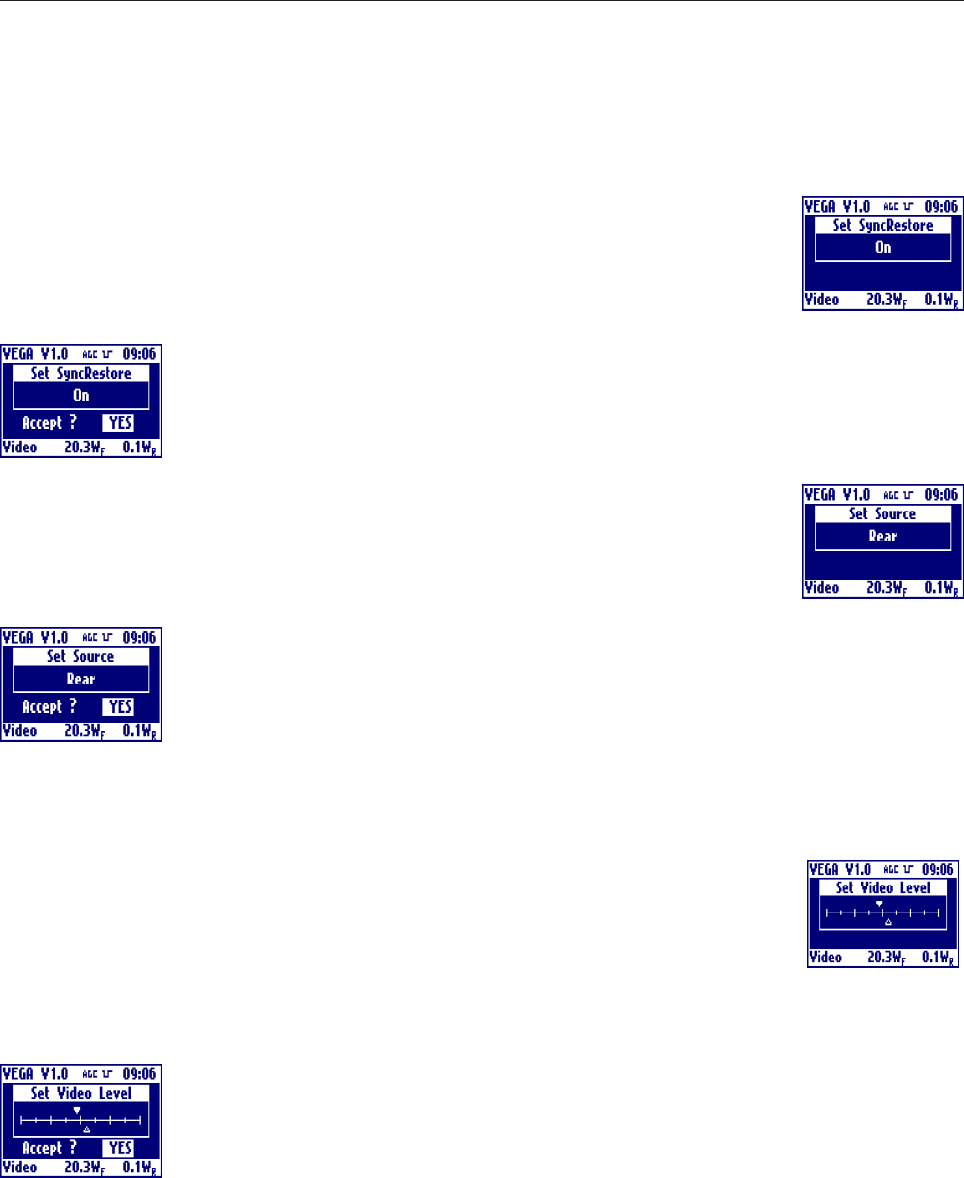
Sync Restore
Clicking on then knob, after selecting this voice, goes into the menu that allows to toggle
the sync restore intervention. Rotate the knob to select the desired value and click on it.
Answer to the confirming question, selecting between accept or not. The answer starts
always from "Accept: NO", so to exit quickly form this menu simply click 2 times on the
knob.
Source
Clicking on then knob, after selecting this voice, goes into the menu that allows to choose
whether to sample the input signal from the front or rear panel. Rotate the knob to select
the desired value and click on it.
Answer to the confirming question, selecting between accept or not. The answer starts
always from "Accept: NO", so to exit quickly form this menu simply click 2 times on the
knob.
Video
Shows the PLL lock or unlock of the video. In case of unlock, the label blinks.
Video Level
Clicking on then knob, after selecting this voice, goes into the menu that allows to sets the
video level. Rotate the knob to select the desired value and click on it.
The actual level is represented by the empty arrow, the full arrow represent the value of
the factory setting of this level. This 'factory default marker' can help you to set-up the exciter to a good value,
without ant instrumentation.
Answer to the confirming question, selecting between accept or not. The answer starts
always from "Accept: NO", so to exit quickly form this menu simply click 2 times on the
knob.
31
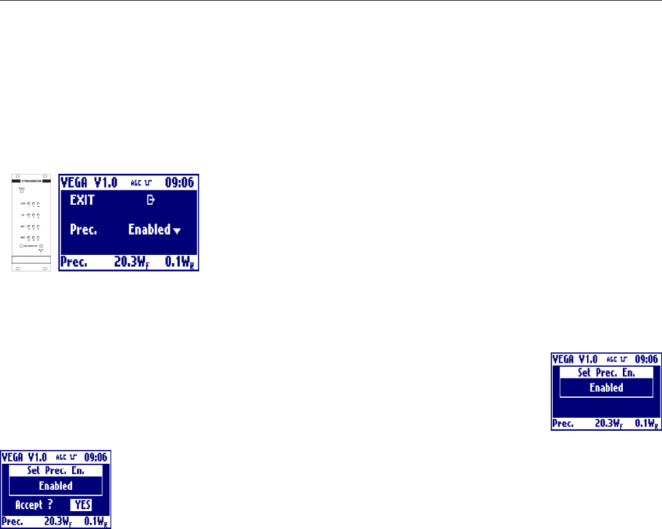
- Multistandard IF Precorrector Section
EXIT
Clicking on the knob, after selecting this voice, goes back to the default menu.
Prec
Clicking on then knob, after selecting this voice, goes into the menu that allows to toggle
the non-linearity pre-corrector. Rotate the knob to select the desired value and click on
it.
Answer to the confirming question, selecting between accept or not. The answer starts
always from "Accept: NO", so to exit quickly form this menu simply click 2 times on the
knob.
32
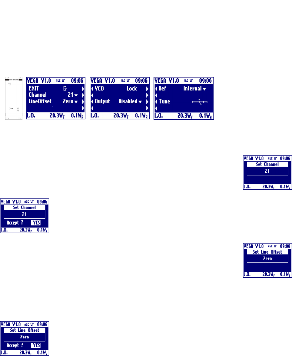
- Multistandard Local Oscillator Section with Line Offset
EXIT
Clicking on the knob, after selecting this voice, goes back to the default menu.
Channel
Clicking on then knob, after selecting this voice, goes into the menu that allows to select
the transmission channel for the selected standard. Rotate the knob to select the desired
value and click on it.
Answer to the confirming question, selecting between accept or not. The answer starts
always from "Accept: NO", so to exit quickly form this menu simply click 2 times on the
knob.
Line offset
Clicking on then knob, after selecting this voice, goes into the menu that allows to set the
line offset in either positive (P) or negative(M) steps from 15M to 15P. Rotate the knob
to select the desired value and click on it.
Offset[Hz] = LineOffset[Step]*(LineFrequency[Hz]/12)
Answer to the confirming question, selecting between accept or not. The answer starts
always from "Accept: NO", so to exit quickly form this menu simply click 2 times on the
knob.
VCO
Shows the oscillator PLL lock or unlock. In case of unlock, the label blinks.
33
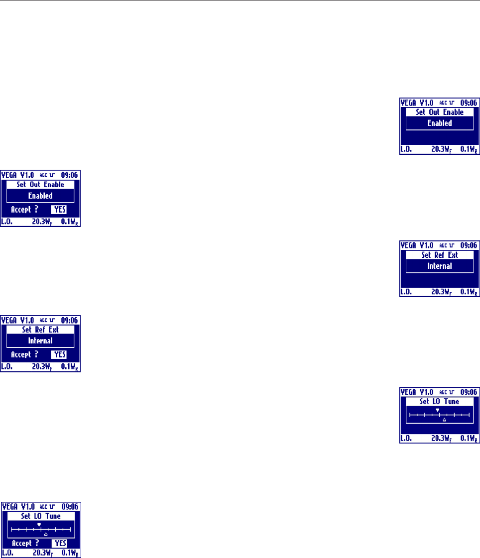
Output
Clicking on then knob, after selecting this voice, goes into the menu that allows to toggle
the oscillator output. Rotate the knob to select the desired value and click on it.
Answer to the confirming question, selecting between accept or not. The answer starts
always from "Accept: NO", so to exit quickly form this menu simply click 2 times on the
knob.
Ref
Clicking on then knob, after selecting this voice, goes into the menu that allows to select
whether the reference is internal or external . Rotate the knob to select the desired value
and click on it.
Answer to the confirming question, selecting between accept or not. The answer starts
always from "Accept: NO", so to exit quickly form this menu simply click 2 times on the
knob.
L.O. Tune
Clicking on then knob, after selecting this voice, goes into the menu that allows to fine
adjust the frequency of Local Oscillator, usefull only in case of absence of an external
reference. Rotate the knob to select the desired value and click on it. The actual level is
represented by the empty arrow, the full arrow represent the value of the factory setting
of this level. This 'factory default marker' can help you to set-up the exciter to a good value, without ant
instrumentation.
Answer to the confirming question, selecting between accept or not. The answer starts
always from "Accept: NO", so to exit quickly form this menu simply click 2 times on the
knob.
34
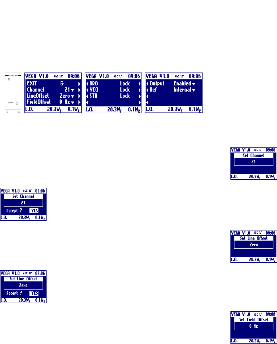
- Multistandard Local Oscillator Section with Field Offset (Option)
EXIT
Clicking on the knob, after selecting this voice, goes back to the default menu.
Channel
Clicking on then knob, after selecting this voice, goes into the menu that allows to select
the transmission channel for the selected standard. Rotate the knob to select the desired
value and click on it.
Answer to the confirming question, selecting between accept or not. The answer starts
always from "Accept: NO", so to exit quickly form this menu simply click 2 times on the
knob.
Line offset
Clicking on then knob, after selecting this voice, goes into the menu that allows to set the
line offset in either positive (P) or negative(M) steps from 15M to 15P. Rotate the knob
to select the desired value and click on it.
Answer to the confirming question, selecting between accept or not. The answer starts
always from "Accept: NO", so to exit quickly form this menu simply click 2 times on the
knob.
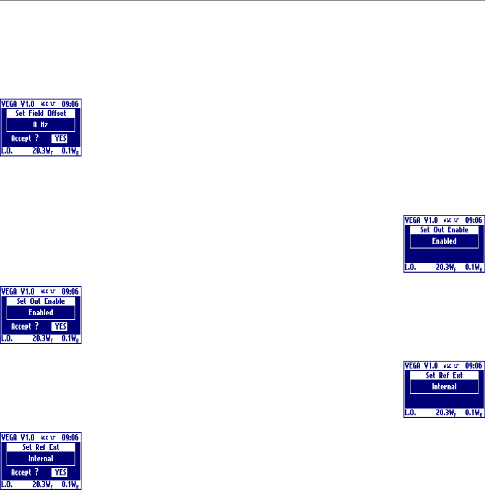
Field offset
Clicking on then knob, after selecting this voice, goes into the menu that allows to set the
filed offset in Hertz from -700Hz to +700Hz. This is added to the line offset. Rotate the
knob to select the desired value and click on it.
TotalOffset[Hz] = FieldOffset[Hz]+LineOffset[Step]*(LineFrequency[Hz]/12)
35
Answer to the confirming question, selecting between accept or not. The answer starts
always from "Accept: NO", so to exit quickly form this menu simply click 2 times on the
knob.
DRO, VCO, STD
Shows the oscillator PLLs lock or unlock. In case of unlock, the label blinks.
Output
Clicking on then knob, after selecting this voice, goes into the menu that allows to toggle
the oscillator output. Rotate the knob to select the desired value and click on it.
Answer to the confirming question, selecting between accept or not. The answer starts
always from "Accept: NO", so to exit quickly form this menu simply click 2 times on the
knob.
Ref
Clicking on then knob, after selecting this voice, goes into the menu that allows to select
whether the reference is internal or external . Rotate the knob to select the desired value
and click on it.
Answer to the confirming question, selecting between accept or not. The answer starts
always from "Accept: NO", so to exit quickly form this menu simply click 2 times on the
knob.
36
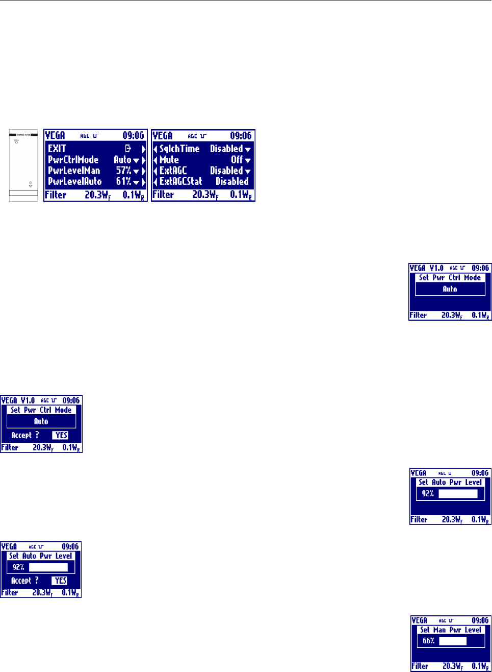
- Multistandard Channel Filter Section
EXIT
Clicking on the knob, after selecting this voice, goes back to the default menu.
PwrCtrlMode
Clicking on then knob, after selecting this voice, goes into the menu that allows to switch
between the manual and automatic (AGC) power control mode. Rotate the knob to
select the desired value and click on it. The Auto or Manual selection will be always
displayed on the top bar.
ATTENTION: for safety operation is better to set 0% to the power level that in not selected.
For example is AUTO power control mode is selected, is better to set 0% to the Power Level in manual
mode. In this way, after a change, the power will start from 0W.
Answer to the confirming question, selecting between accept or not. The answer starts
always from "Accept: NO", so to exit quickly form this menu simply click 2 times on the
knob.
Auto Pwr level
Clicking on then knob, after selecting this voice, goes into the menu that allows to select
the operating level of the power in case of automatic power control mode selected.
Rotate the knob to select the desired value and click on it.
Answer to the confirming question, selecting between accept or not. The answer starts
always from "Accept: NO", so to exit quickly form this menu simply click 2 times on the
knob.
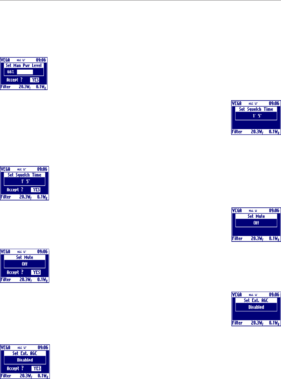
Manual Pwr level
Clicking on then knob, after selecting this voice, goes into the menu that allows to select
the operating level of the power in case of manual power control mode selected. Rotate
the knob to select the desired value and click on it.
37
Answer to the confirming question, selecting between accept or not. The answer starts
always from "Accept: NO", so to exit quickly form this menu simply click 2 times on the
knob.
SqlchTime
Clicking on then knob, after selecting this voice, goes into the menu that allows to
choose the squelch time. This is the time without input signal after which the VEGA mute
the power amplifier. This time can be choose a steps of 5 seconds and can also be
disabled, in this can the VEGA will never mute the power amplifier with or without the
input signal.
Rotate the knob to select the desired value and click on it.
Answer to the confirming question, selecting between accept or not. The answer starts
always from Accept: NO, so to exit quickly form this menu simply click 2 times on the
knob.
Mute
Clicking on then knob, after selecting this voice, goes into the menu that allows to toggles
between mute or not the power amplifier. Remember that Mute On means No Power.
Rotate the knob to select the desired value and click on it.
Answer to the confirming question, selecting between accept or not. The answer starts
always from Accept: NO, so to exit quickly form this menu simply click 2 times on the
knob.
ExtAgc
Clicking on then knob, after selecting this voice, goes into the menu that allows to toggle
between enable or disable external agc. Before enabling it please read the external agc
implementation details.
Rotate the knob to select the desired value and click on it.
Answer to the confirming question, selecting between accept or not. The answer starts
always from Accept: NO, so to exit quickly form this menu simply click 2 times on the
knob.

38
ExtAgcStat
Shows the External AGC working status. It can be:
·Disabled: AGC disabled by local or remote menu setting.
·Idle: AGC temporary stopped (for example caused by -3dB power reduction without sync).
·Low Set: AGC stopped because external power reading too low when VEGA power has been choosed.
·Alarm: AGC stopped because Alarm signal set by Amplifier section.
·Lock: AGC has reached the desired power.
·Max/Min: AGC stopped because the correction is too hi.
·Pull Up/Down: AGC is moving Up or Down the power.
39
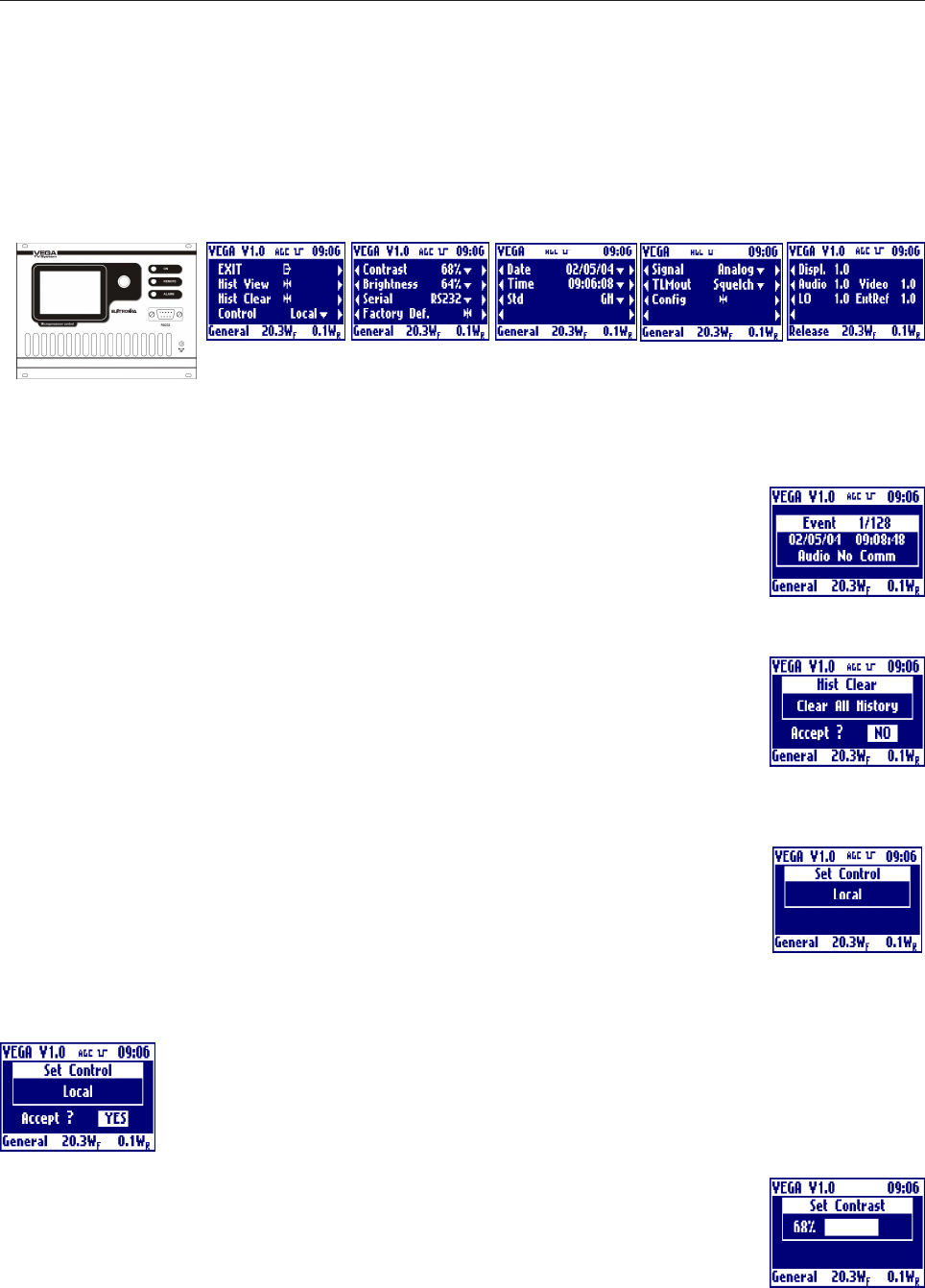
- Controller Module Section
EXIT
Clicking on the knob, after selecting this voice, goes back to the default menu.
Hist View
Clicking on then knob, after selecting this voice, goes into the menu that allows to show
all the events stored into the non volatile memory of the VEGA. In the title bar is showed
the current event number and the total events actually stored into the log. To move inside
the log simply rotate the knob. Click the knob to exit from the history view.
Hist Clear
Clicking on then knob, after selecting this voice, goes into the menu that allows to clear
all the events stored in the history log.
Answer to the confirming question, selecting between accept or not. The answer starts
always from "Accept: NO", so to exit quickly form this menu simply click 2 times on the
knob.
Control
Clicking on then knob, after selecting this voice, goes into the menu that allows totoggle
the local or remote control mode. Rotate the knob to select the desired value and click
on it.
When in remote mode either the telemeasuring connector or the serial port can be used to control the exciter.
Telemeasuring connector and serial port can be always used to monitor the exciter.
Answer to the confirming question, selecting between accept or not. The answer starts
always from "Accept: NO", so to exit quickly form this menu simply click 2 times on the
knob.
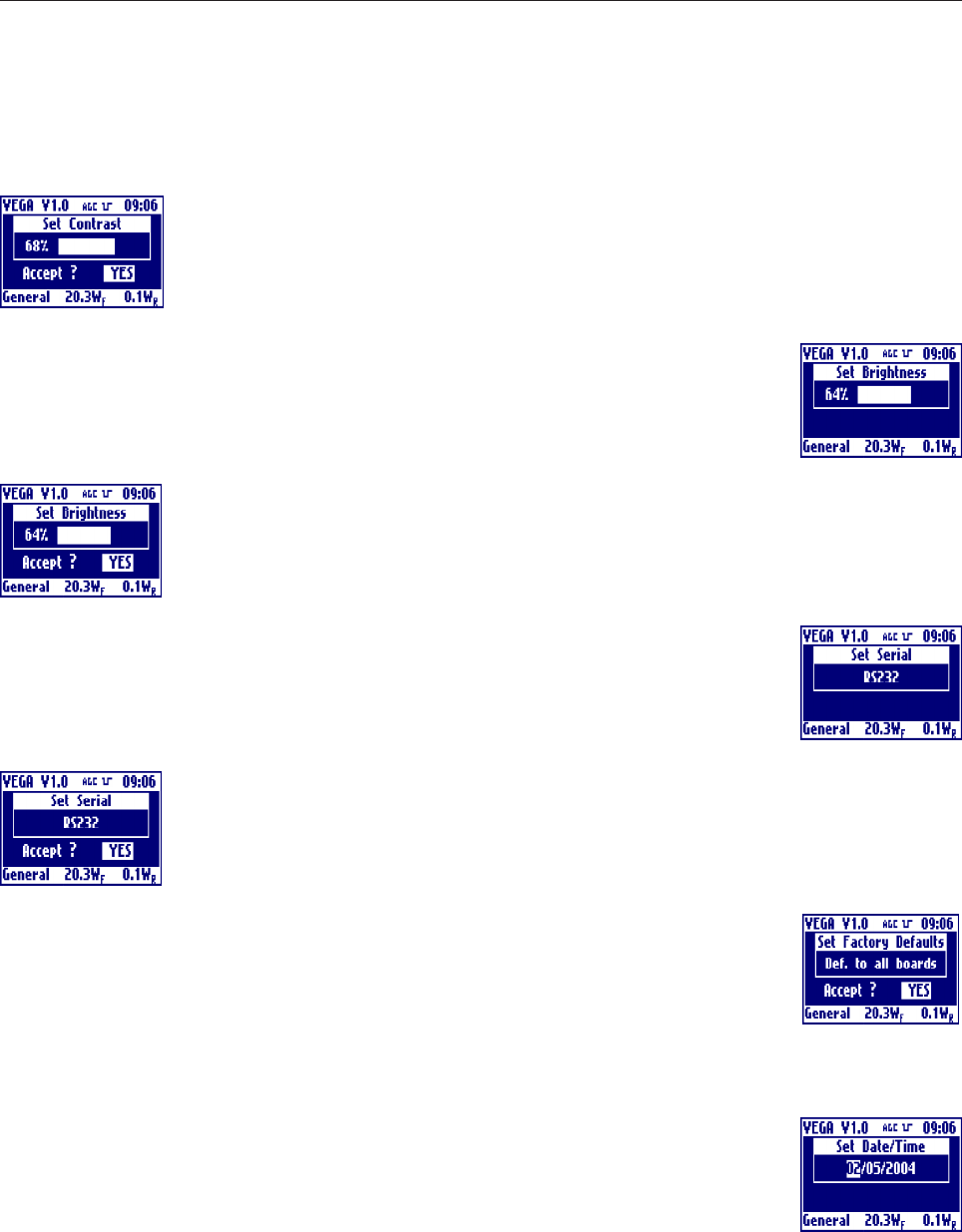
Contrast
Clicking on then knob, after selecting this voice, goes into the menu that allows to adjust
the contrast settings of the display. Rotate the knob to select the desired value and click
on it.
40
Answer to the confirming question, selecting between accept or not. The answer starts
always from "Accept: NO", so to exit quickly form this menu simply click 2 times on the
knob.
Brightness
Clicking on then knob, after selecting this voice, goes into the menu that allows to adjust
the brightness settings of the display. Rotate the knob to select the desired value and
click on it.
Answer to the confirming question, selecting between accept or not. The answer starts
always from "Accept: NO", so to exit quickly form this menu simply click 2 times on the
knob.
Serial
Clicking on then knob, after selecting this voice, goes into the menu that allows to toggle
between the possibility for serial port control: RS232 on the front panel and RS485 on
the rear panel. Rotate the knob to select the desired value and click on it.
Answer to the confirming question, selecting between accept or not. The answer starts
always from "Accept: NO", so to exit quickly form this menu simply click 2 times on the
knob.
Factory Def
Clicking on then knob, after selecting this voice, goes into the menu that allows to reste all
of the parameters of the VEGA to values set during the factory tests.
Answer to the confirming question, selecting between accept or not. The answer starts
always from "Accept: NO", so to exit quickly form this menu simply click 2 times on the knob.
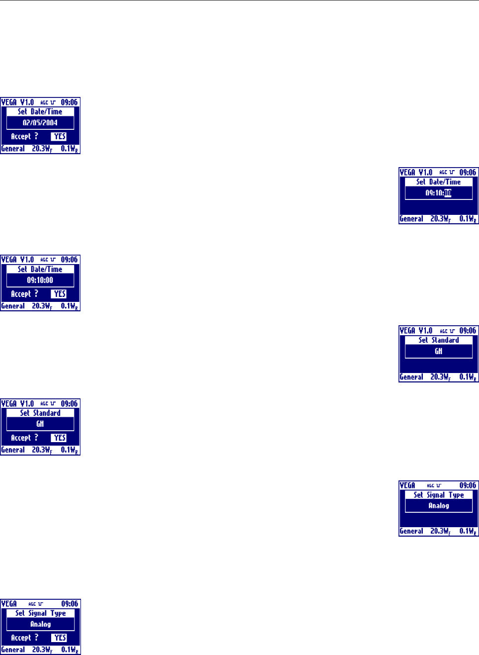
Date
Clicking on then knob, after selecting this voice, goes into the menu that allows to set the
date of the internal clock of the display board.
Rotate the knob to select the desired value and click on it, the selection will go to the next
filed.
The date format is day/month/year.
41
Answer to the confirming question, selecting between accept or not. The answer starts
always from "Accept: NO", so to exit quickly form this menu simply click 2 times on the
knob.
Time
Clicking on then knob, after selecting this voice, goes into the menu that allows to set the
time of the internal clock of the display board. Rotate the knob to select the desired value
and click on it, the selection will go to the next filed.
The time format is hour/minute/second.
Answer to the confirming question, selecting between accept or not. The answer starts
always from "Accept: NO", so to exit quickly form this menu simply click 2 times on the
knob.
Std
Clicking on then knob, after selecting this voice, goes into the menu that allows to set the
standard used. Rotate the knob to select the desired value and click on it.
Answer to the confirming question, selecting between accept or not. The answer starts
always from "Accept: NO", so to exit quickly form this menu simply click 2 times on the
knob.
Signal
Clicking on then knob, after selecting this voice, goes into the menu that allows to select
the signal type handled by the VEGA. Rotate the knob to select the desired value and
click on it.
If 'Digital' signal type is selected the sync detection is disabled. In the same way is disabled the 3dB power
reduction feature in case of AGC power control and Sync lost.
In case of Digital signal type selection the sync icon in the top bar will be replaced by a 'DIG' icon.
Answer to the confirming question, selecting between accept or not. The answer starts
always from "Accept: NO", so to exit quickly form this menu simply click 2 times on the
knob.
42
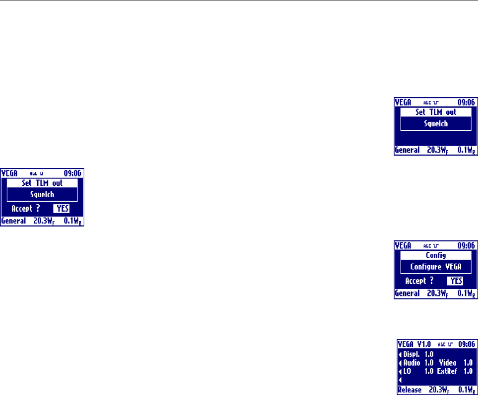
TLMout
Clicking on then knob, after selecting this voice, goes into the menu that allows to toggles
between Squelch or Alarm meaning of the output free contact of the Telemeasure
connector. Rotate the knob to select the desired value and click on it.
Answer to the confirming question, selecting between accept or not. The answer starts
always from "Accept: NO", so to exit quickly form this menu simply click 2 times on the
knob.
Config
Clicking on then knob, after selecting this voice, goes into the menu that allows to go in
the Configuration menu of VEGA to change the VEGA boards topology. This possibility
is enabled only in Factory Setting mode. Answer to the confirming question, selecting
between accept or not. The answer starts always from Accept: NO, so to exit quickly
form this menu simply click 2 times on the knob.
Releases
Clicking on then knob, after selecting this voice, goes into the menu that allows to view
all the release history of all the microcontrollers around the VEGA boards. The display
board is showed in the first line and then the audio, video, local oscillator and external
reference.
43
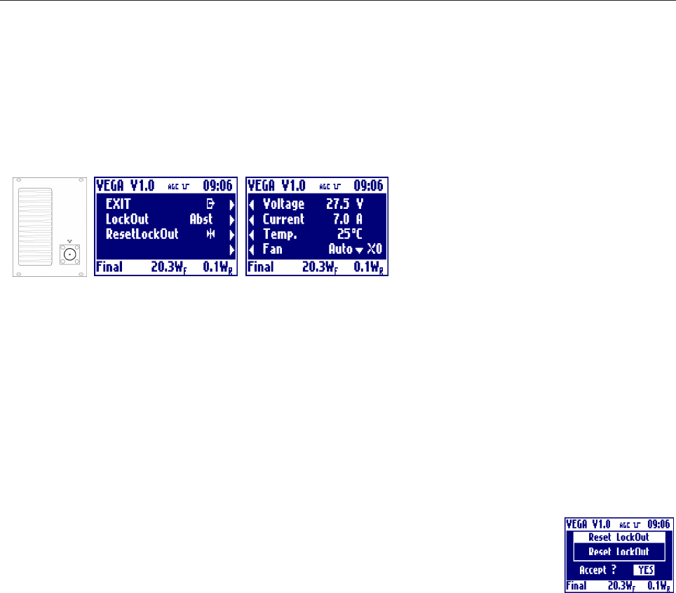
- RF Amplifier Module Section
EXIT
Clicking on the knob, after selecting this voice, goes back to the default menu.
LockOut
Shows whether the LockOut state is present or absent. In case of presence of LockOut, the label blinks.
Below is detailed the functioning of LockOut.
While an alarm is present the exciter switch off the output power. When the alarm disappear, the power is
switched on again. After 5 times the exciter switch off the output power, the exciter goes in LockOut state: the
power remains off till the user reset the LockOut. If the fails are far more that 1 hour than the LockOut counter
is automatically cleaned.
ResetLockOut
Clicking on then knob, after selecting this voice, goes into the menu that allows to clear
LockOut counter.
Answer to the confirming question, selecting between accept or not. The answer starts
always from "Accept: NO", so to exit quickly form this menu simply click 2 times on the knob.
Voltage
Shows the measure of the power supply voltage of the final power stage. In case of abnormal value, the label
blinks.
Current
Shows the measure of the power supply current of the final power stage. In case of abnormal value, the label
blinks.
Temp.
Shows the measure of the working temperature of the final power stage. In case of abnormal value, the label
blinks.
Fan
Shows the operating mode of the fan, which may run at low or high speed, be still or be programmed to work
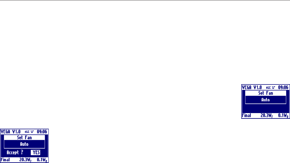
44
automatically depending on the temperature of the final stage. The fan symbol on the right shows the fan
speed: 0, 1 or 2 means respectively stopped, low and high speed.
Clicking on then knob, after selecting this voice, goes into the menu that allows to set the
standard used. Rotate the knob to select the desired value and click on it.
Answer to the confirming question, selecting between accept or not. The answer starts
always from "Accept: NO", so to exit quickly form this menu simply click 2 times on the
knob.
45
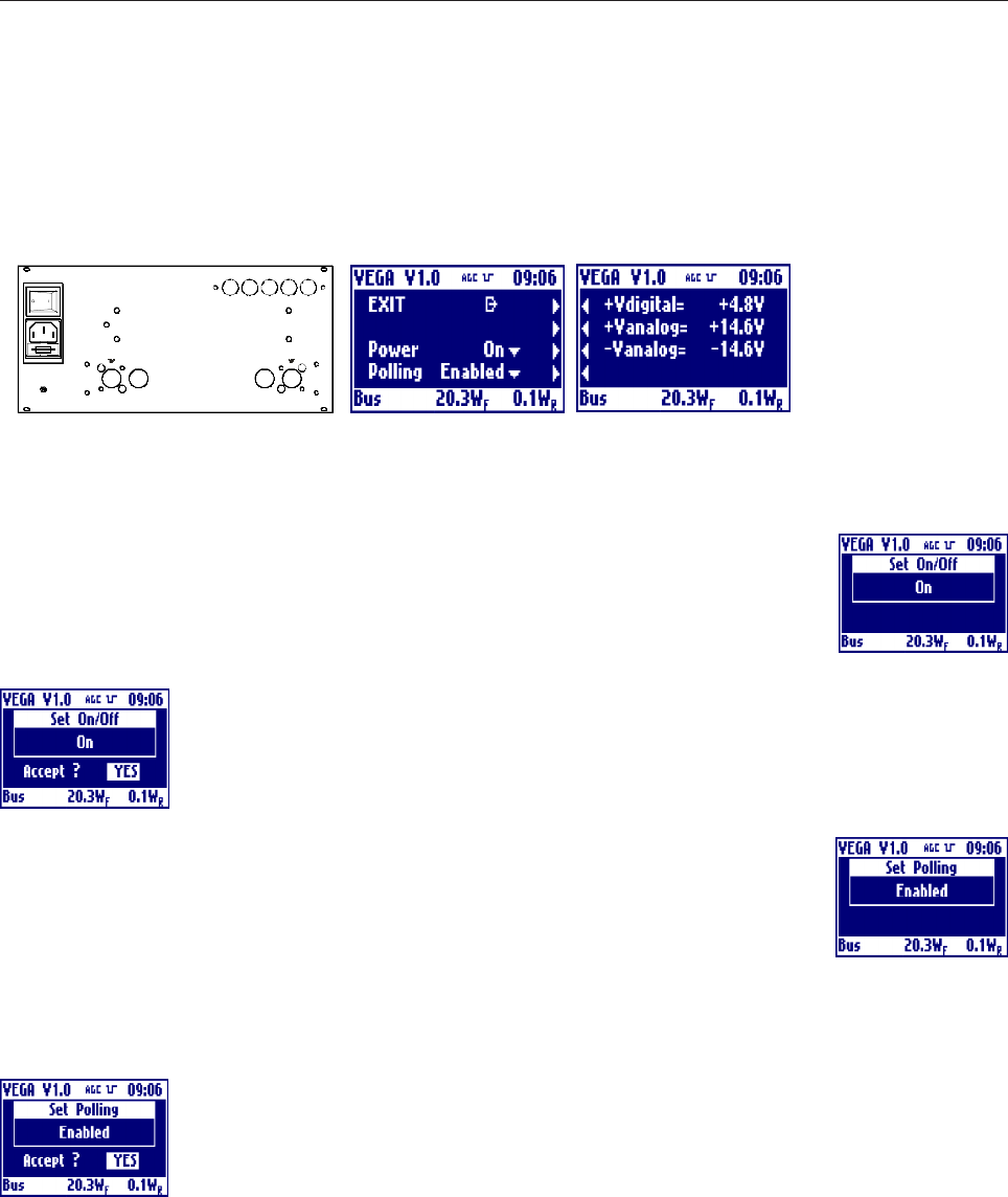
- BUS Structure Section
EXIT
Clicking on the knob, after selecting this voice, goes back to the default menu.
Power
Clicking on then knob, after selecting this voice, goes into the menu that allows to turns
on or off the power supply of the whole BUS. Rotate the knob to select the desired value
and click on it.
Answer to the confirming question, selecting between accept or not. The answer starts
always from "Accept: NO", so to exit quickly form this menu simply click 2 times on the
knob.
Polling
Clicking on then knob, after selecting this voice, goes into the menu that allows to turns
on or off the BUS polling feature. Rotate the knob to select the desired value and click
on it.
If 'BUS polling' enabled the display board will poll continuously all the board to obtain
the data values. If 'BUS polling' disabled the boards will inform by using an interrupt line
that a value has changed on them.
Answer to the confirming question, selecting between accept or not. The answer starts
always from "Accept: NO", so to exit quickly form this menu simply click 2 times on the
knob.
+Vdigital
Shows the measure of the +5V power supply voltage of the bus. In case of abnormal value, the label blinks.
+/-Vanalog
Shows the measure of the +/-15V power supply voltage of the bus. In case of abnormal value, the label
blinks.
46
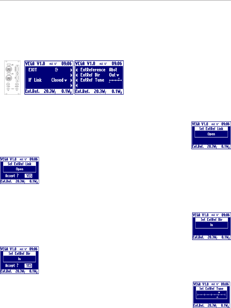
- External Reference Section
EXIT
Clicking on the knob, after selecting this voice, goes back to the default menu.
IF link
Clicking on then knob, after selecting this voice, goes into the menu that allows to choose
whether the IF connection is internal or located on the rear panel. Rotate the knob to
select the desired value and click on it.
Answer to the confirming question, selecting between accept or not. The answer starts
always from "Accept: NO", so to exit quickly form this menu simply click 2 times on the
knob.
ExtReference
Shows whether the external reference is present.
ExtRef Dir
Clicking on then knob, after selecting this voice, goes into the menu that allows to set the
direction of the reference. Rotate the knob to select the desired value and click on it.
Answer to the confirming question, selecting between accept or not. The answer starts
always from "Accept: NO", so to exit quickly form this menu simply click 2 times on the
knob.
ExtRef Tune
Clicking on then knob, after selecting this voice, goes into the menu that allows to fine
adjust the frequency of the external reference. Rotate the knob to select the desired value
and click on it. The actual level is represented by the empty arrow, the full arrow represent
the value of the factory setting of this level. This 'factory default marker' can help you to set-up the exciter to

47
a good value, without ant instrumentation.
Answer to the confirming question, selecting between accept or not. The answer starts
always from "Accept: NO", so to exit quickly form this menu simply click 2 times on the
knob.

48
2.3 ALARMS AND AUTOMATION
In case of alarm the red LED lights up and the icon of a bell appears in the upper bar of the display. If the alarm
disappears, the red LED is turned off and the bell starts blinking, in order to show that an anomaly occurred.
To know the details of the anomaly and when it occurred, the history menu can be used. Once this menu is
accessed, the blinking bell icon disappears.
In case of alarms of a board on the bus, such as the audio or the video modulator, the green status led on the
board, will start blinking. When the board is working correctly the led is lit continuously.
In case of alarm of a board on the Bus, a bell icon appears under the board image in the front or rear view
menu. Inside the board menu the alarm value will blink.
TRICK: in case of red alarm LED lit, to quickly find the alarm move between the front and rear view and
look for the bell symbol under a board. If present go inside the board menu looking for the blinking value.
While an alarm is present the exciter switch off the output power. When the alarm disappear, the power is
switched on again. After 5 times the exciter switch off the output power, the exciter goes in LockOut state: the
power remains off till the user reset the LockOut. If the fails are far more that 1 hour than the LockOut counter
is automatically cleaned.
Please find below the list of the automatic interventions of the exciter in case of anomalies, and the relevant
record in the history.
l Amplifier Voltage
No intervention. The history records and intervention if the value is too high or too low by the 10% of its
nominal value (factory setting).
l Amplifier Current
No intervention. The history records an event if the value is too high by the 20% of its nominal value (factory
setting), only when the amplifier is on.
l Amplifier Temperature
The temperature is connected to the work of the fan, if it is set to automatic mode, in this way: there are 3
thresholds, TH1 < TH2 < TH3, all with histeresys.
Under the lowest threshold (TH1) the fan is off
Between TH1 and TH2 the fan is on and rotates slowly
Between TH2 and TH3 the fan is on and rotates fast
Beyond the higher threshold (TH3) the amplifier is switched off and an event is recorded in the history.

49
If the temperature drops again below TH3, the amplifier is switched back on.
A fast sequence of on/off switching causes a LockOut of the apparatus.
l BUS Voltages (+5V, +15V, -15V)
No intervention. The history records and intervention if the value is too high or too low by the 10% of its
nominal value.
l Forward & Reflected Power
If the value of the forward power exceeds the threshold value (factory setting) the ampifier is switched off and
the event is recorded in the alarm history.
l No communication with the boards on the BUS
No intervention. The history records the event only if Polling is enabled. If Polling is disabled, the No
communication is not detected.
If a board is not communicating a ! symbol appears under the board image in the front or rear menu.
l Non-corresponding standards
There is no intervention in case one or more boards on the BUS are set to work on different standards. The
history records the event.
l IF Audio unlock
The audio board turns off its IF in case it becomes unlocked. The history records the event.
l Audio Overload
The menu of the audio board indicated the event with a blinking 'Triggered' message. The history does not
record any event.
l IF Video unlock
The video board turns off its IF in case it becomes unlocked. The history records the event.
Besides, the final amplifier is switched off.
l Video Clipper
The menu of the video board indicated the event with a blinking 'Triggered' message. The history does not
record any event.
l L.O. unlock
The local oscillator board turns its output off if any of its PLL unlocks. The history records the event.
50
Besides, the final amplifier is switched off.
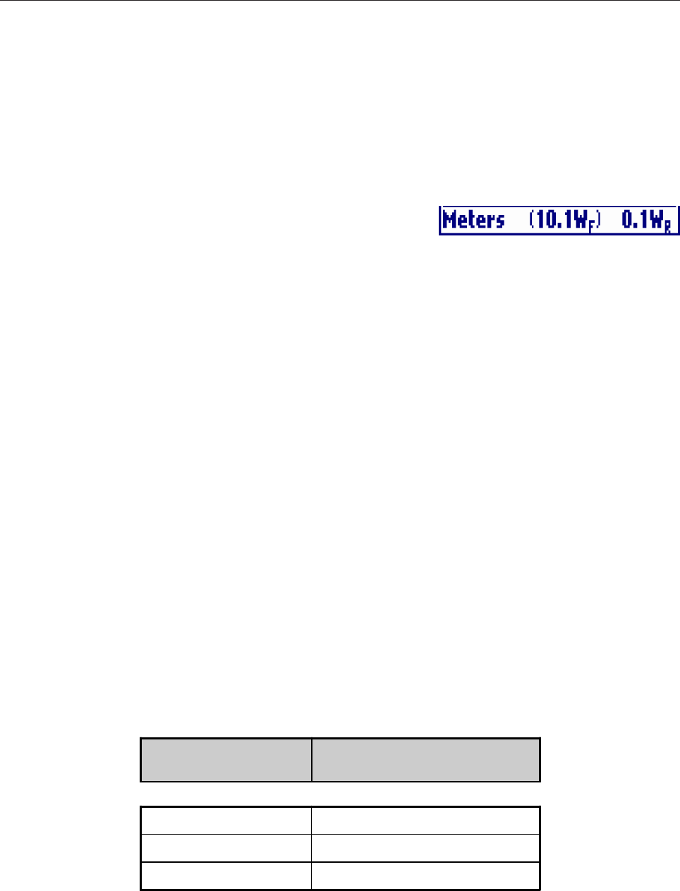
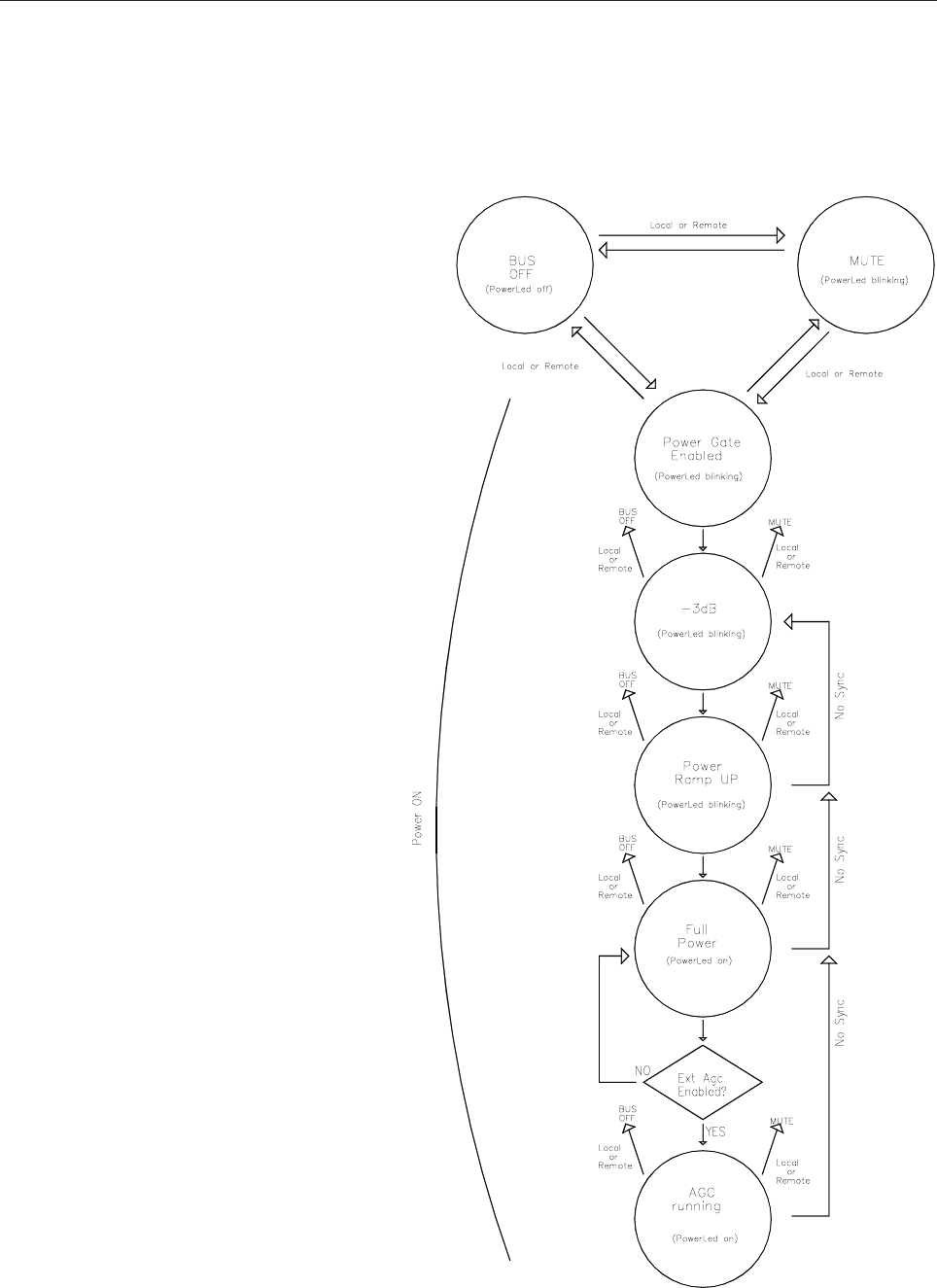
l No Sync
In case the synchronism is missing the sync icon in the top bar blinks.
In this case the value of the output power is decreased by 3dB only
if analog signal type is selected and AGC control is selected. In case of 3dB otput power decrease, the output
power value in the bottom bar will be written between round brackets.
l Squelch
After a selectable time the video input signal is missing the VEGA mute the output power. When the video
signal come back the output power is switched on. During the squelch period the output power (0W) will be
written between square brackets.
2.4 EXTERNAL AGC: IMPLEMENTATION AND DETAILS
Scope
This paper explain the External AGC implementation inside VEGA TV Transmitter.
The use of External AGC help the VEGA Transmitter to maintain stable the Output Power. With a menu
setting you can choose between stabilizing the output power of VEGA transmitter (External AGC disabled)
or stabilizing the output power of a bigger transmitter with the VEGA acting as driver/modulator (External
AGC enabled). In this case a cabling is necessary between VEGA and Power Section.
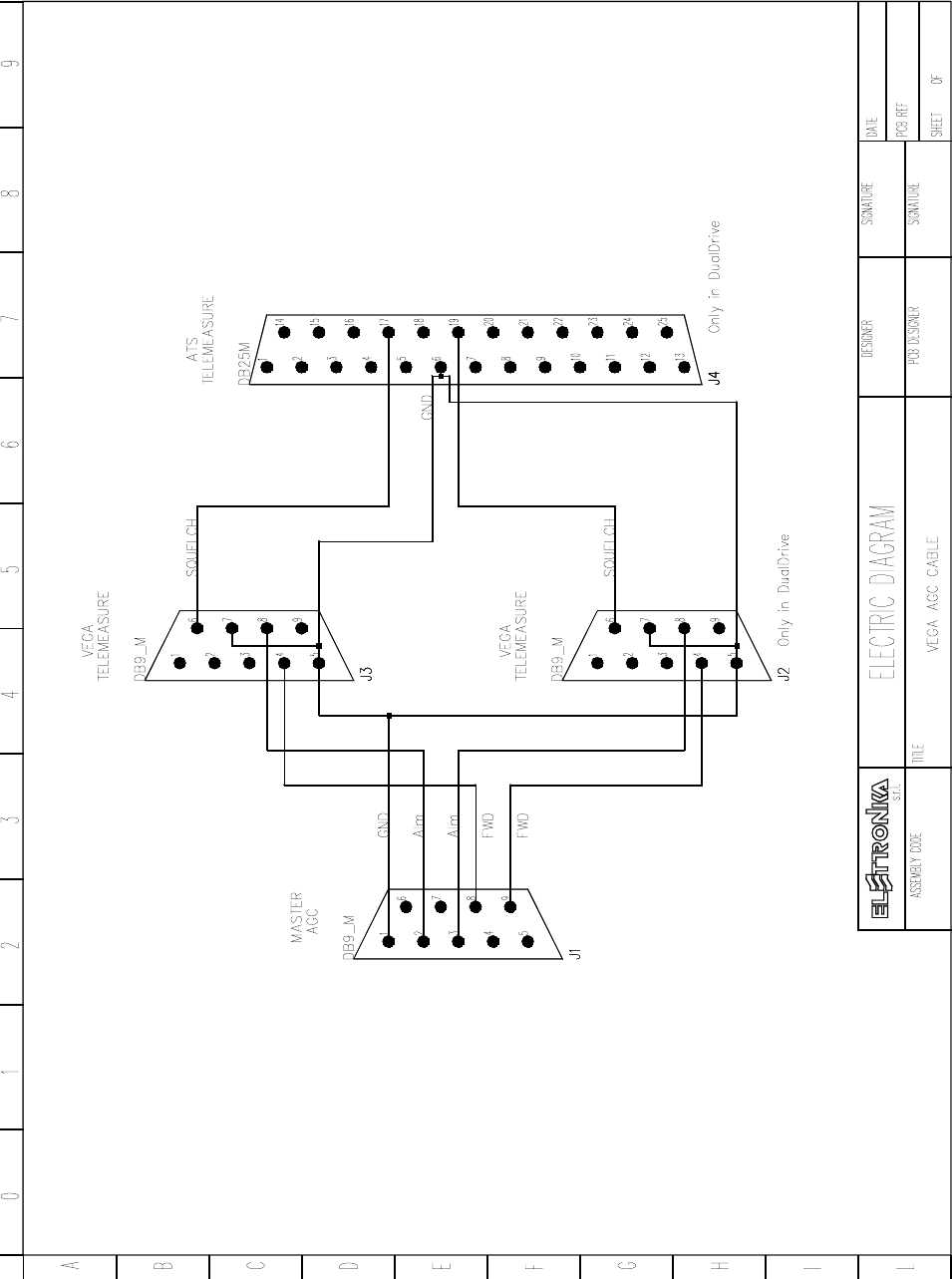
Cabling
In case of AGC stabilizing output power of a transmitter where VEGA acts as Driver, the VEGA needs to be
connected to the Amplifier section with a cable connected to VEGA Telemeasuring port. The corresponding
pin on the Amplifier side depends on the specific amplifier used.
VEGA
DB9 TELEMEASURE AMPLIFIER
5GND
4¬ FWD Power (0 - 5V)
8¬ Alarm (0V= Alarm - 5V= Ok)
51

52
AGC implementation
The AGC goal is to maintain stable the output power. Output power in fact can change due to the increase of
amplifier temperature. Note that when you change the operating frequency the output power change due to
the different gain at different frequency, but this change is not stabilized by this AGC algorithm. The power to
stabilize is read from external telemerasuring connector.
To keep the power stable the AGC change the power gain of VEGA.
The AGC algorithm is based on the acquisition of the optimal output power level (stored when you confirm
VEGA output power, exiting from the power level menu) and the use of 4 thresholds as below:
______action threshold
____________goal threshold
__________________optimal power value
____________goal threshold
______action threshold
The distance of thresholds from optimal value is of ±20 mV and ±30 mV measured as monitor voltage.
The AGC change output VEGA power in order to have power inside goal threshold. When this goal is
achieved the AGC stops until the power goes outside action threshold.
The AGC work is stopped immediately (output power remains blocked to that reached in the moment of the
AGC stop) when one of this condition occurs:
·One of VEGA alarms is triggered.
·AGC is chosen as external and Amplifier section triggers an alarm.
·VEGA output power too low
·AGC has change the VEGA output power too much.
In order to simplify the understanding of AGC state, this is written in the AGC menu. The possible states of
AGC are:
·Disabled: AGC disabled by local or remote menu setting.
·Idle: AGC temporary stopped (for example caused by -3dB power reduction without sync).
·Low Set: AGC stopped because external power reading too low when VEGA power has been choosed.
·Alarm: AGC stopped because Alarm signal set by Amplifier section.
·Lock: AGC has reached the desired power.
·Max/Min: AGC stopped because the correction is too hi.
·Pull Up/Down: AGC is moving Up or Down the power.
WARNING: When changing from AUTO to MANUAL power control mode, the External AGC will be disabled.
53
2.5 POWER HANDLING
The VEGA Power handling is characterised
by 3 state:
·BUS OFF: the boards on the Bus are off
and the power amplifier is switched off
·MUTE: the board on the Bus are switched
on and working. Only the power amplifier is
switched off.
·POWER ON: the boards and the power
amplifier are switched on and working. This
is the normal working functioning.
Moving between the 3 states is always
possible by using the display menu or by
remote connection. Moreover the state of
POWER ON is characterised by a sequence
of steps. The sequence is detailed in the
Power Handling diagram.
54
2.6 VEGA FACTORY SETTING
The VEGA display board stores some settings and fine tunings inside its not erasable memory. The storing
occurs while the VEGA is tested in factory before the sell. To enter in Factory Setting mode a dip-switch is
used.
DIP2 On (VEGA display board): Factory setting.
Note that DIP2 is set to ON only during the factory setup of the exciter. This allow to store in the memory all
of the settings made as factory defaults. Once the test is completed, and while the modulator is used normally,
the DIP2 must be kept OFF.
One of the factory setting stored during this phase is the set point of all the digital trimmer in the menu list. If
you take a look at a digital trimmer it has two wiper: one is filled and the other is empty. The filled can be
moved ONLY during the phase of Factory Setting. In this way, during the normal operation of VEGA, if the
user try to move a set point and forget the original value can easily go back to the factory set point, without any
instrumentation.
All other settings available in the phase of Factory Setting are present in some hidden menu described below.
All the hidden menu are located at the right of the Front menu.
Fwd Max
Clicking on then knob, after selecting this voice, goes into the menu that allows to
change the trigger point of the Forward Max alarm. Rotate the knob to select the desired
value and click on it.
Reflected Max
Clicking on then knob, after selecting this voice, goes into the menu that allows to
change the trigger point of the Reflected Max alarm. Rotate the knob to select the
desired value and click on it.
55
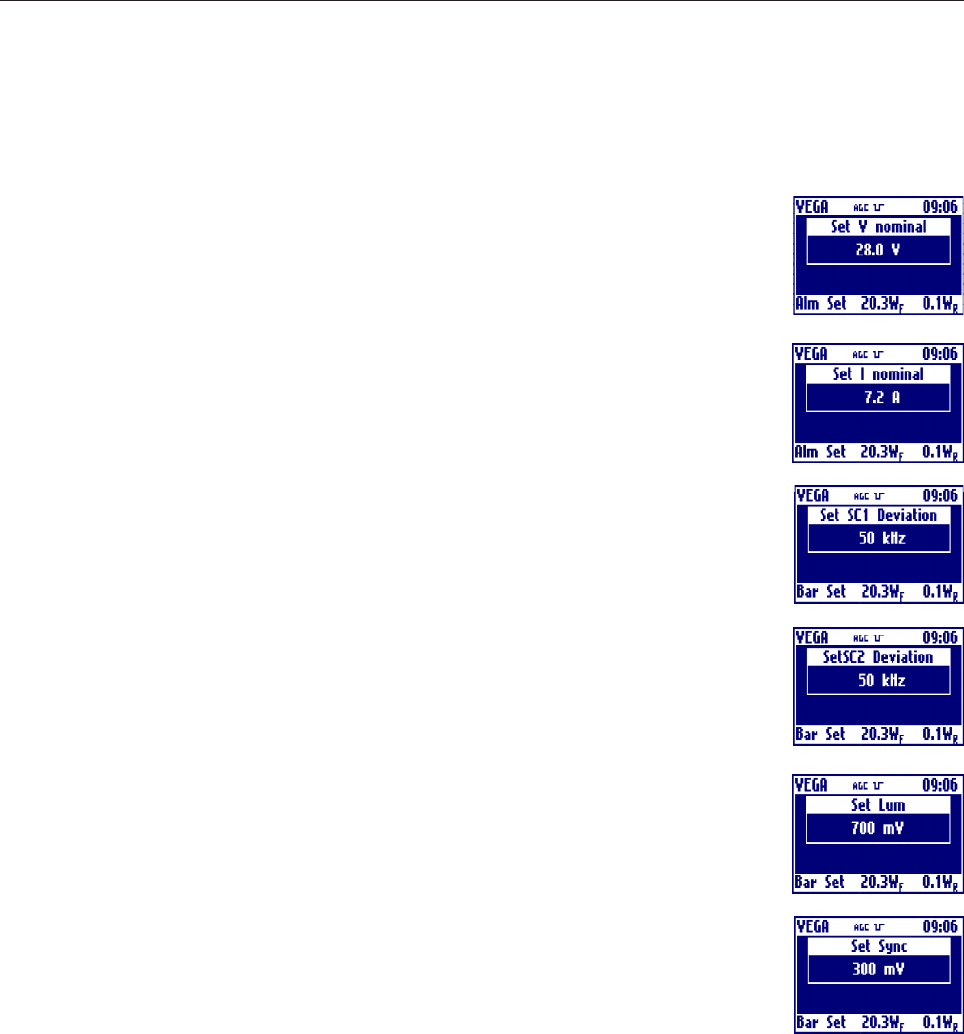
Nominal Voltage
Clicking on then knob, after selecting this voice, goes into the menu that allows to
change the value of the nominal voltage of the power supply of the power amplifier.
Rotate the knob to select the desired value and click on it.
Nominal Current
Clicking on then knob, after selecting this voice, goes into the menu that allows to
change the value of the nominal current of the power supply of the power amplifier.
Rotate the knob to select the desired value and click on it.
SubCarrier1 Deviation
Clicking on then knob, after selecting this voice, goes into the menu that allows to change
the value of Audio Sub Carrier 1 deviation. Rotate the knob to select the desired value
and click on it.
SubCarrier2 Deviation
Clicking on then knob, after selecting this voice, goes into the menu that allows to
change the value of Audio Sub Carrier 2 deviation. Rotate the knob to select the desired
value and click on it.
Luminance Level
Clicking on then knob, after selecting this voice, goes into the menu that allows to
change the level of luminance. Rotate the knob to select the desired value and click on
it.
Sync Level
Clicking on then knob, after selecting this voice, goes into the menu that allows to change
the level of sync. Rotate the knob to select the desired value and click on it.
- Setup Configuration
During Setup Configuration in the VEGA is manually entered which board is present or not on the BUS. This
modality is entered the first time the display board of the VEGA is programmed and by using the Config
menu in the General menu sequence. This menu is available only in Factory Setting mode.
Entered in Setup Configuration the user have to insert the working modality of VEGA: Transmitter, Repeater
or Amplifier.
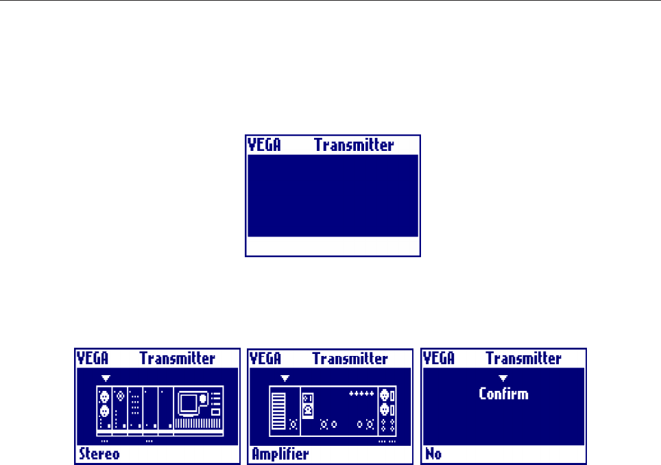
56
Then the user have to choose which kind of boards are connected on the bus, moving between front and read
view. The modifiable boards are that with symbol under them.
Once entered the configuration the user has to go in the rightmost windows and choose the Confirm to change
the actual configuration.