Elettronika S r l TXUP5000 TXUP5000 5 kW Analog TV Transmitter User Manual APT120A AUTV 5000LD Rev0 Date221003 p65
Elettronika S.r.l. TXUP5000 5 kW Analog TV Transmitter APT120A AUTV 5000LD Rev0 Date221003 p65
Contents
- 1. User Manual Part 1
- 2. User Manual Part 2
- 3. User Manual Part 3
User Manual Part 3
103
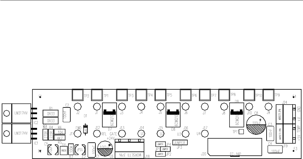
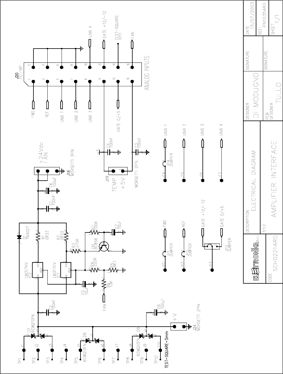
AMPLIFIER INTERFACE SCH0221AR0
Component layout SCH0221AR0
COMPONENT LIST SCH0221AR0
Part Name/Number Description Qty. Comps.
CC 100nFAVX 01065A 01065A CERAMIC COND 4 C1-4
CE 100uF100V 01795B ELETT. COND. 1 C8
CE 100uF50V 01795 01795 ELETT. COND. 1 C6
CE 10uF35V-S 01778A 01778A ELETTR SMD COND 2 C5, C7
D 1N4007 03009 03009 DIODE 1 D1
D 6CWQ10FN 03026 SMD DIODE SCHOTTKY 3,5A 3 D7-9
IC LM317HV 04340A INTEG CIRCUIT 2 IC1-2
J FC-16P 02701-02700 02701+02700 PCB CONNECTOR POL 1 J20
J SCREWCONN2 02853 02853 PCB SCREW CONNECTOR 2 J19, J24
J SCREWCONN3 02860 02860 PCB SCREW CONNECTOR 1 J18
J TESTP1.3mm 07913 07913 TEST POINT 17 J1-17
JU JUMP2 02739-02742 02739+02742 MASCHIO PAN2 3 JP1-2, JP4
JU JUMP3 02707-02742 02707+02742 MASCHIO PAN3 1 JP3
R 0R33-1W-S 00380 RES 1W 5% SMD 2512 2 R1-2
R 100K-S 00065A 00065A RES 1/4W 5% SMD 1206 1 R7
R 10K-S 00053A 00053A RES 1/4W 5% SMD 1206 1 R6
R 220R-S 00033A 00033A RES 1/4W 5% SMD 1206 1 R4
R 270R-S 00034A 00034A RES 1/4W5% SMD 1206 1 R3
R 4K7-S 00049A 00049A RES 1/4W 5% SMD 1206 1 R5
TR BC856 03455 03455 PNP SMD TRANSISTOR 1 TR1
104
105
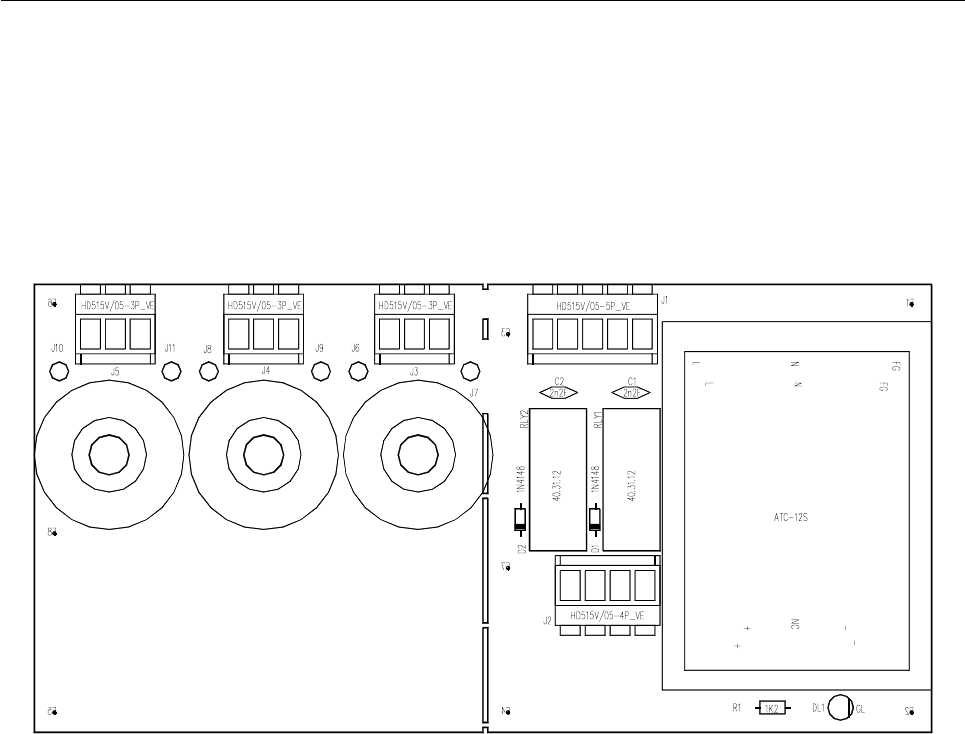
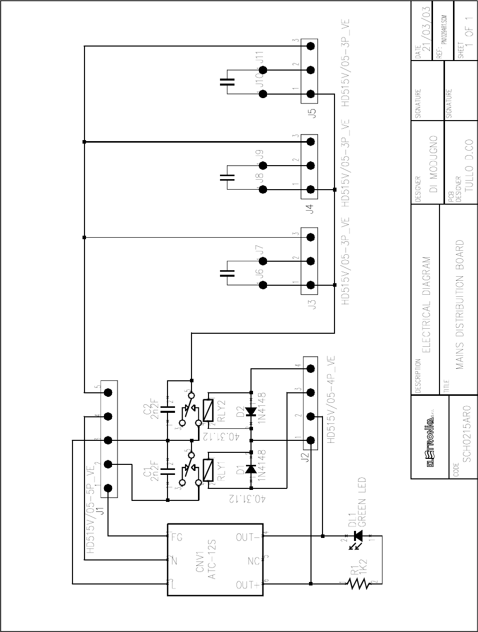
MAINS DISTRIBUTION BOARD SCH0215AR0
Component layout SCH0215AR0
COMPONENT LIST SCH0215AR0
Part Name/Number Description Qty. Comps.
CC 2nF2 2kV 01045A 01045A CERAMIC COND 2 C1-2
CNV AC-DC ATC-12S AC DC CONVERTER 1 CNV1
D 1N4148 03001 03001 DIODE 2 D1-2
DL LEDG3 03053 03053 GREEN LED DIODE 3mm 1 DL1
J CON HD515V/05-3PVE PANDUIT PCB CO 3 J3-5
J CON HD515V/05-4PVE 02881 + 02882 PANDUIT PCB CONN 1 J2
J CON HD515V/05-5PVE PANDUIT PCB CO 1 J1
J TESTP1.3mm 07913 07913 TEST POINT 6 J6-11
R 1K2 0042 0042RES 1/4W 5% 1 R1
RL 40.31.12 07567 07567 RELE 2 RLY1-2
106
107
TECHNICAL CHARACTERISTICS
- Input characteristics
Vin: 100..240Vrms
REND.: 80%
lin@FL: 16..6,5Arms
PF>0.95@FL (PFC)
- Output characteristics
Pout: 1300W on 2 outputs
Vout: 2 options a) 32Vdc 40A on 2 outputs
b) 52Vdc 25A on 2 outputs
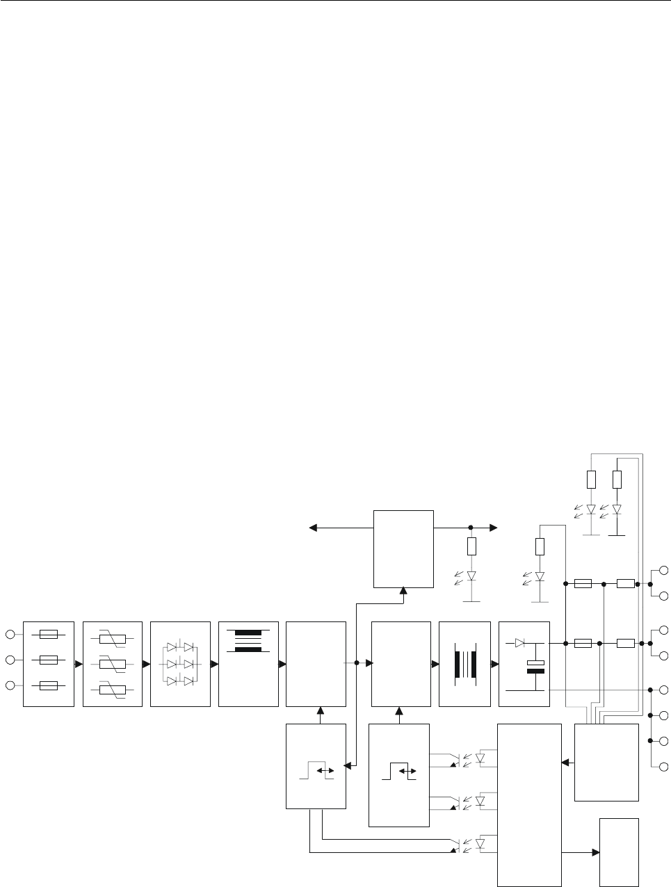
Block Diagram
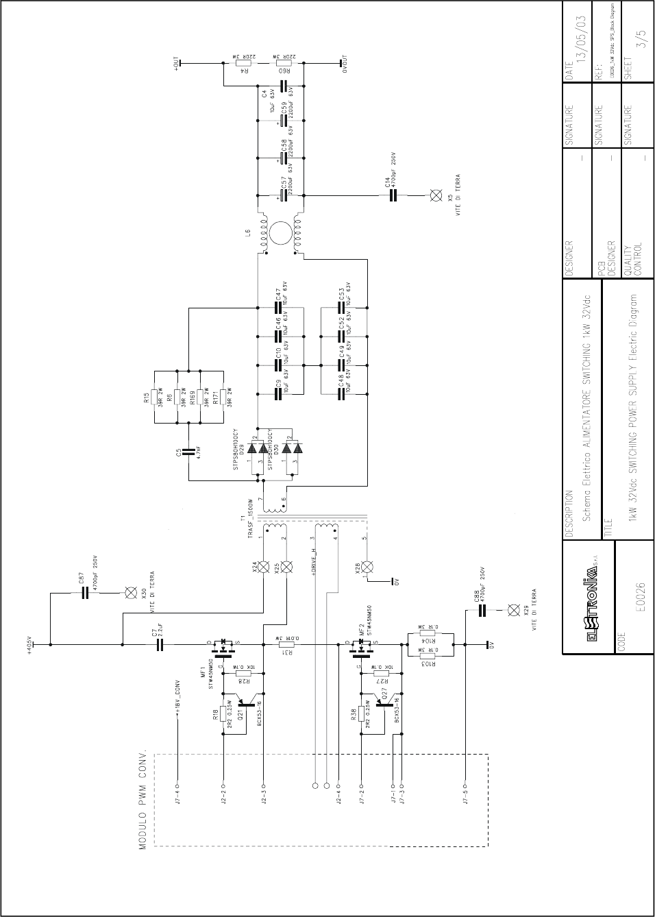
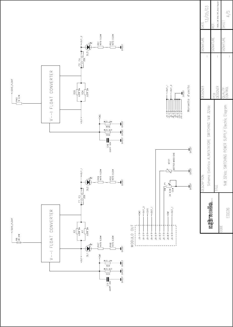
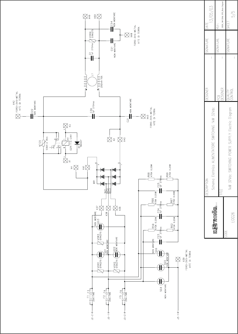
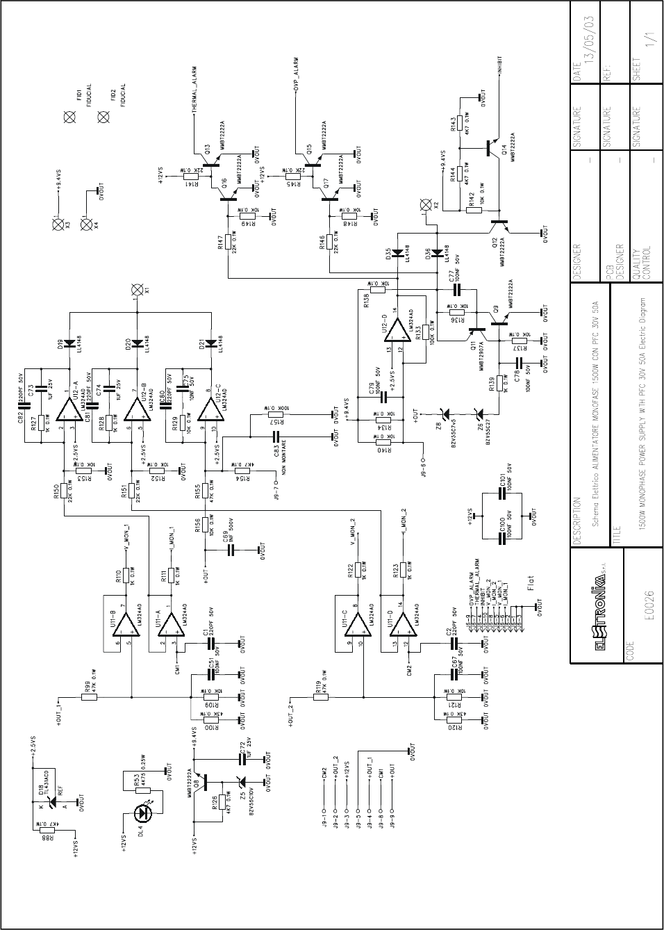
1kW 32Vdc SWITCHING POWER SUPPLY E0026
AUX
PRIM
AUX
AUX
SEC
L R
N S
T EMI
FILTER
PFC
POWER
STAGE
MAIN
CONVERTER
POWER
STAGE
+1
1
+2
+2
OUTPUT
CONTROL
AND
PROTECTION
MONITOR
FLAT
10PIN
Feedback
inhibit
inhibit
108
109
110
111
112
113
114
115

116
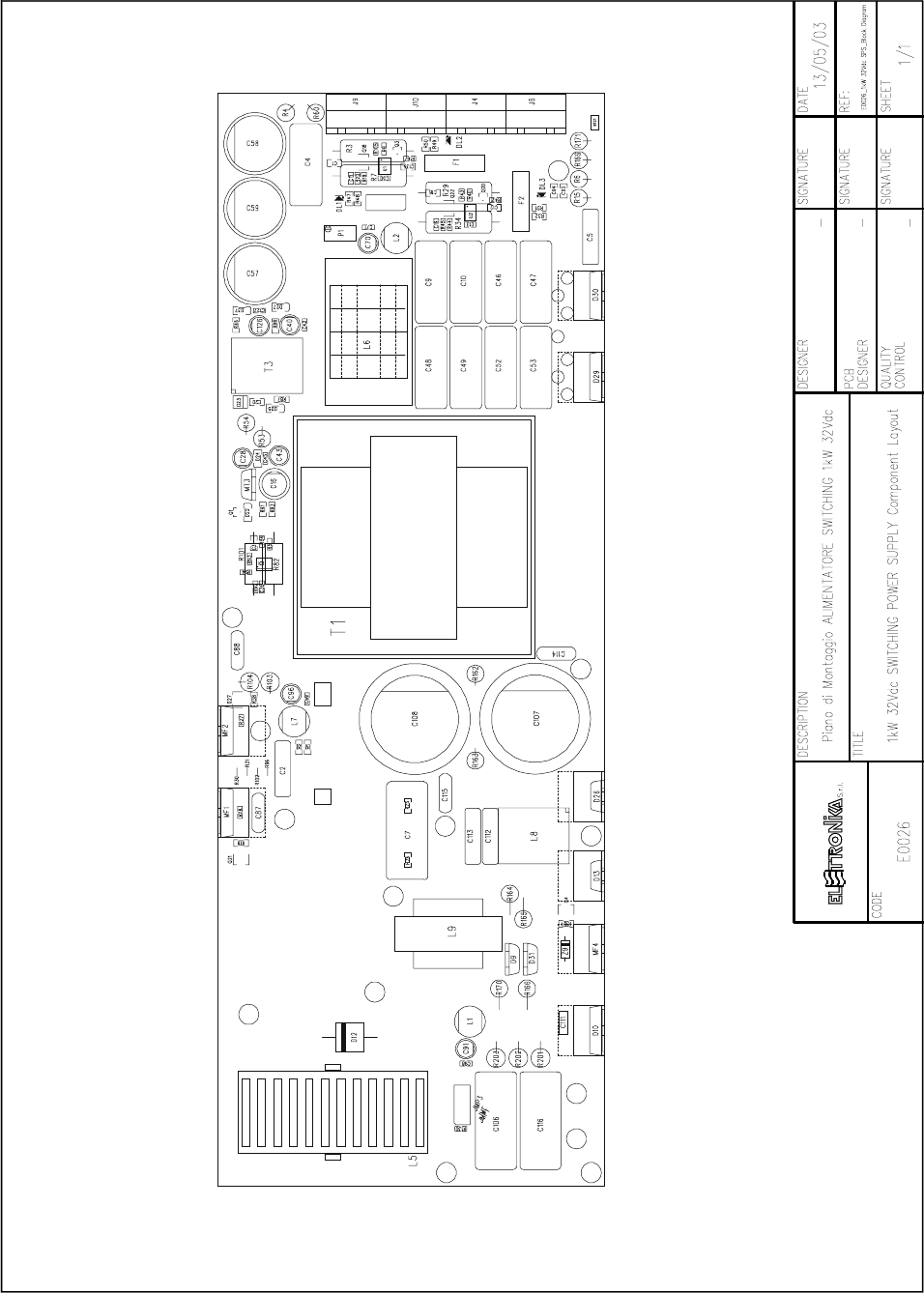
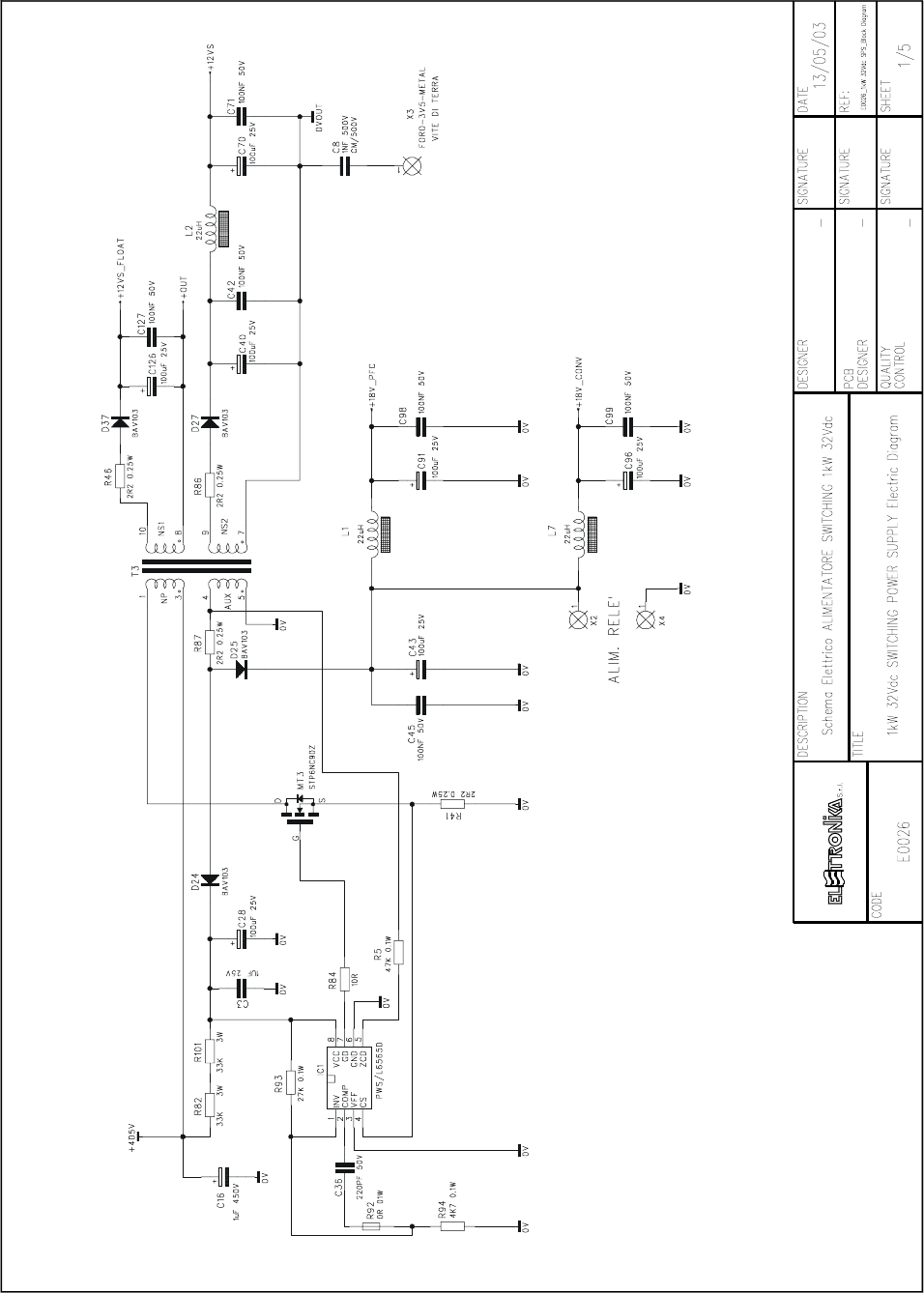
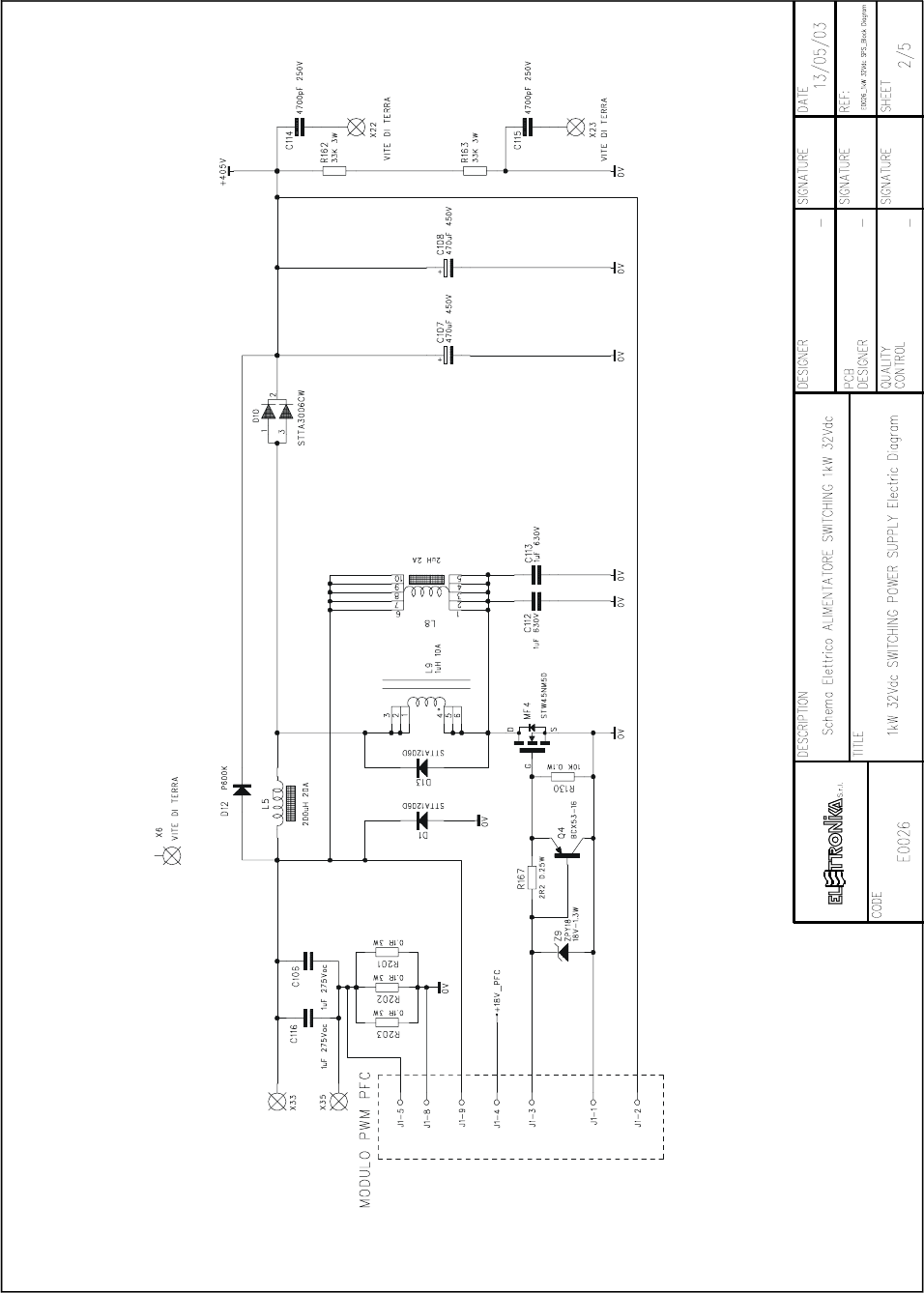
COMPONENT LIST 1kW 32Vdc Switching Power Supply
SMT COMPONENT
IT QTY STORE-CODE DESCRIPTION REF. Page 1/2
1 1 03.B04.0000A CHIP RES.0805 STR.MET.0.10W 0Ohm 5% R92
2 2 03.B05.0003B 100R 1% 0.1W RES. SMD 0805 100PPM R16, R42
3 3 03.B05.0006B 10K 1% 0.1W RES. SMD 0805 100PPM R27-28, R130
4 4 03.B05.0009B 1K 1% 0.1W RES. SMD 0805 100PPM R8, R40, R43, R105
5 3 03.B05.0014B 27K 1% 0.1W RES. SMD 0805 100PPM R20, R45, R93
6 1 03.B05.0020B 47K 1% 0.1W RES. SMD 0805 100PPM R5
7 3 03.B05.0061B 4K7 1% 0.1W RES. SMD 0805 100PPM R19, R44, R94
8 1 03.B05.0150B 150R 1% 0.1W RES. SMD 0805 100PPM R84
9 6 03.B10.0267B 4K75 1% 1% 25W RES. SMD 1206 100PPM R47-52
10 9 03.B17.0003B 2R2 1% 0.25W RES. SMD MINIMELF 100PPM R1-2, R18, R38, R41, R46,
R86-87, R167
11 2 03.B17.0010B 100K 1% 0.25W RES. SMD MINIMELF 100PPM R75-76
12 1 03.B25.0002A 0.01R 1% 3W RES. SMD 4527 WSR3 100PPM R31
13 8 03.D02.0004A COND. CRM MSTR Z5U 100NF 50V 20% SMT-0805 C13, C42, C45, C50, C71,
C98-99, C127
14 3 03.D02.0012A 220PF 50V 5% 0805 SMD COND. CMR X7R C11, C19, C36
15 3 03.D04.0004A 1NF 500V 10% 1206 SMD COND. CRM MSTR C8, C93-94
16 5 03.D04.0007A 1uF 25V 10% 1206 SMD GRM42-6 (MURATA) C1, C3, C12, C18, C135
17 1 05.B02.0014A L6565D FLYBACK QUASI-RESONANT CONTROL. IC1
18 2 05.B04.0010A LMC6482AIM DUAL CMOS SOP-8 OP.AMP UI-2
19 2 04.D00.0001A MMBT2222A BJT NPN 40V 1A 0.35W Hfe100-300 Q3, Q20
20 1 04.D00.0501A MMBT2907A BJT PNP -60V 0.8A 0.35W Hfe100-300 Q1
21 5 04.D00.0502A BJT PNP -80V -1A 1W Hfe 100 Ty. BCX53-16 Pk. SOT-89
(M.code: AL) Q4, Q18, Q21-22, Q27
22 6 04.B01.0001A BAV103 SMD DIODO SILICIO 200MA 250V PKG. SOD80 D1, D22, D24-25, D27,
D37
23 3 04.K00.0002A DIODO LED VERDE SMD 1206 BRIGHTLED DL1-3
THT COMPONENT
IT QTY STORE-CODE DESCRIPTIO REF. Page 1/2
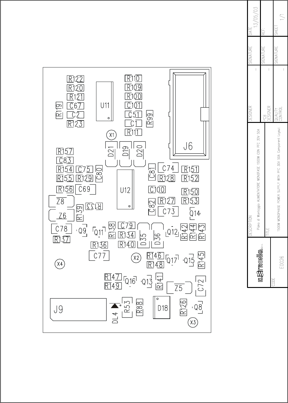
24 1 CIRCUITO STAMPATO D.N. D06.0203A_00R02
25 4 Morsetto Phoenix MKDS5/2-9.5 J4, J6, J9-10
26 1 RELAY 24VDC 16A G2R-1-E-24VDC OMRON K1
27 5 0,1R 5% 3W RES. OSSIDO. MET. R103-104, R201-203
28 2 220R 5% 3W RES. OSSIDO. MET. R4, R60
29 2 33KOhm 5% 3W RES. OSSIDO MET. R162-163
30 4 39R 5% 2W RES. OSSIDO MET. 250ppm R6, R15, R169, R171
31 2 100K 5% 2W RES. OSSIDO MET. 250ppm R82, R101

117
IT QTY STORE-CODE DESCRIPTION REF. Page 2/2
32 4 RESISTORE A FILO 0,01R 2W 5% R3, R7, R29, R34
33 1 Potenziometro Cermet 20Giri 2KOhm 0.5W 10% 100ppm
Ty: 67W P1
34 5 4700pF 250W COND. CRM CLASSE X1 Y2 P.7,5 C6, C15, C17, C87-88
35 1 100nF 600V 5% Cond. film mylar scat 7.5x17.5mm P.15 C2
36 2 1UF 275Vac X2COND. FILM. SCAT. 12.5x32.5mm P27.5 C106, C116
37 1 COND. FILM MYLAR SCATOLINO 4.7nF 250V 10% 5x17.5
P. 15 (mm) C5
38 2 1uF 630V COND. FILM SCAT. 18x32.5mm P.27.5 C112-113
39 9 10uF 63 COND. RAD. POLIES. 10% P22.5 10x25 (mm) C4, C9-10, C46-49, C52,
C53
40 1 Condensatore FILM SCATOLINO 2.2uF 400V 10% P.27,5 C7
41 2 470uF 450V 20% ETL SNAP-IN 20% ins. Radiale d35 / h52mm C107-108
42 7 COND. ETL AL 100uF 25V d6,3x11mm P.2,5 C28, C40, C43, C70, C91,
C96, C126
43 3 COND. ETL AL 220uF 63V 20% ins. Radiale d20 / h42mm P7.5 C57-59
44 1 COND. ETL 1uF 450V 20% ins. Radiale d8 / h11.5 P.3.8 (mm) C16
45 3 INDUTTORE 22uH I-MAX 2A PASSO 200 L1-2, L7
46 1 TRASF. DI POT. T0203.04R01 D.N. STT0203_04R01 T1
47 1 TRASF. AUX T0203.05R02 D.N. STT0203_05R02 T3
48 1 BOBINA SNUBBER PFC T0211.03R01 D.N. STT0211_03R01 L9
49 1 BOBINA CLAMPER PFC T0211.02R02 D.N. STT0211_02R02 L8
50 1 BOBINA PFC T0203.01R00 D.N. STT0203_01R00 L5
51 1 BOBINA DI MODO COMUNE T0203.06R00 D.N. STT0203 L6
52 1 NTC 10R DIAM. 9,5mm P.5 B57-235-S100M NTC5
53 1 NTC EPCOS B57045K0103K000 NTC1
54 2 FUSIBILE AUTO AL 25A 32V F3-4
55 4 CLIP PORTAFUSIBILE PER AUTO PZ1011 (OMEGA) F1-2
56 1 P600K DIODO RADDRIZZ. SILICIO 6A 800V D12
57 1 STTA3006CW DOPPIO DIODO ULTRA FAST TO247 D10
58 2 STT1206D TO220 D. TURBOSWITCH 600V 12A D9, D13
59 2 STPS80H100CY 100V 4X20 MAX TO247 D29, D30
60 1 DIODO ZENER 1,3W 18V ZPY18 DO-41 5% Z9
61 1 STP6NC90Z 900V 6A ENHAN. MODE N-MOSFET MT3
62 3 STW45NM50 TO247 500V 45A MOSFET MF1-2, MF4
63 1 COND. CER. MULTISTRATO 1uF 50V P.5 C14
Note:
within the notes:
- the V prefix is for Vertical mounting
- the M prefix stands for Mechanical details
118
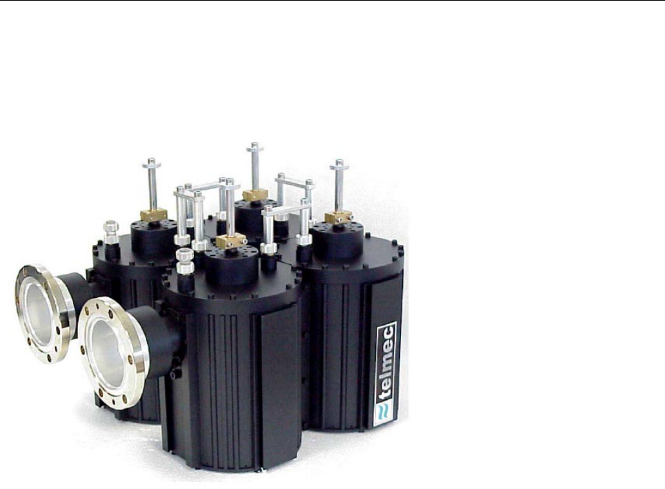
UHF 5/10kW ANALOG TV FILTER Code 06663
Suitable for use in solid state A-AB
class transmitter, in common
amplification, to eliminate out of band
products in all standard frequencies.
Available connectors:
- EIA 1 5/8
- RIGID LINE 1 5/8
- EIA 3 1/8
opposite or parallel position.
TECHNICAL CHARACTERISTICS
Configuration 4 Cavities
Max power output 10kW (cw)
Frequency range 470 - 860MHz
Insertion loss (Video c.) < 0,2dB
Return loss > 30dB
Temperature range -10°C / +50°C
Temperature shift < = 2kHz/K
Weight 20kg
Working position Any
Dimensions 395x380x347mm
119
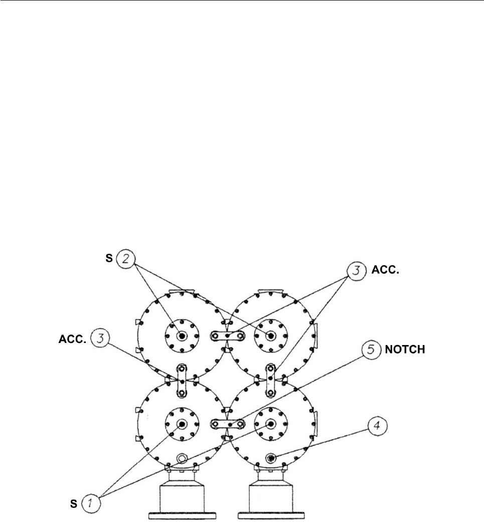
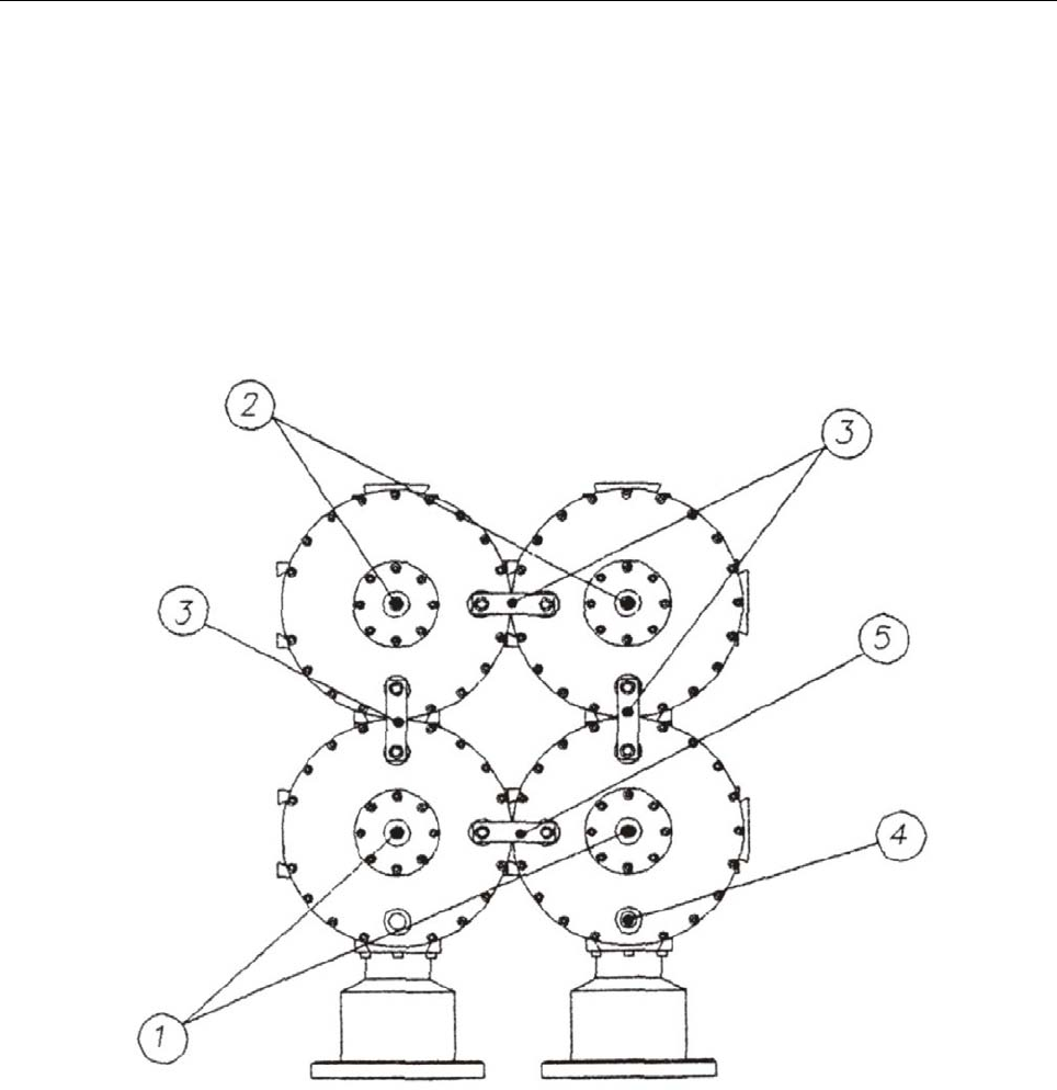
CALIBRATION PROCEDURE
In order to calibrate PBN153/44, a double-track Network Analyser is needed, in order to visualize the
frequency response of the passing and reflected signals.
- Calibration procedure from 470MHz to 666MHz
1. Extract the coupling 5 (Fig. 1) until it stops.
2. Insert the couplings 3, letting about 5mm out.
3. Connect the filter to the Network Analyser marking the input. Select the frequency of the desired channel
centre and set a SPAN of 50MHz.
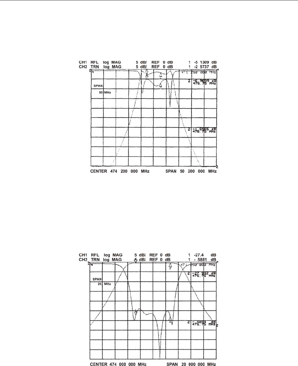
4. Act on the tuning rods 1 and 2 until the curve of the band-pass appears in the centre of the screeen, and
adjust it by means of the couplings 3 to obtain a width of about 10MHz (Fig. 2).
120
Fig. 2
5. Set a SPAN of 20MHz and act alternatively on:
- Interstage coupling 3 (rise and lower);
- IN/OUT couplings 4 (turn);
- Tuning 1 and 2 (rise and lower);
to obtain a bandwidth of 7-8MHz and an adaptation of about 25dB, composed by four peaks (Fig. 3).
Fig. 3
6. Insert the coupling 5 (Fig. 1) to set the position of the notch attenuation on the desired frequencies (Fig. 4)
(5.5MHz and +11MHz or 4-5MHz and +9MHz).
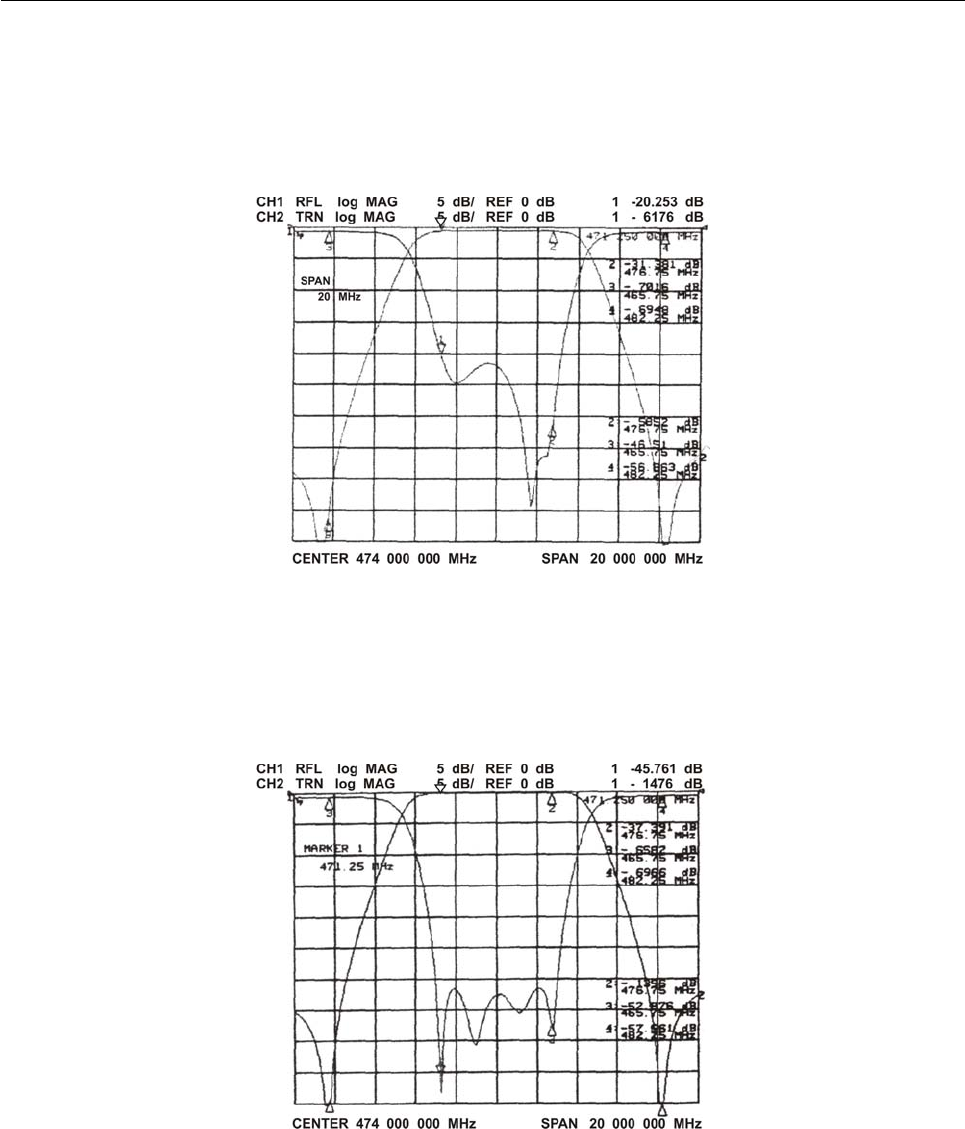
121
Fig. 4
7. The adaptation has moved; it can be adjusted by acting on the filter as per point 6, correcting each time the
attenuation tuning by means of the coupling 5, until a frequency response like that in the example (Fig. 5) is
obtained.
Fig. 5
8. Once the calibration is complete, the machanical movement during the locking stage will have to be
compensator for, because a variation of the adaptation may occur. It only takes to extract slightly the tuning
which is being fastened.
122
- Calibration procedure from 66MHz to 860MHz
1. Extract the coupling 5 (Fig. 1) until it stops.
2. Extract the couplings 3 making sure not to short-circuit them.
3.Connect the filter to the Network Analyser, marking the input. Select the frequency of the desired centre
channel and set a SPAN of 50MHz.
4. Act on the tuning rods 1 and 2 until the curve of the band-pass appears in the centre of the screen and
adjust it by means of the coupling 3 to obtain a width of about 10MHz (Fig. 2). The tuning 2, due to the
elliptical system according to which the filter has been designed, will compose the attenuation of the notch as
well as the curve of the band-pass.
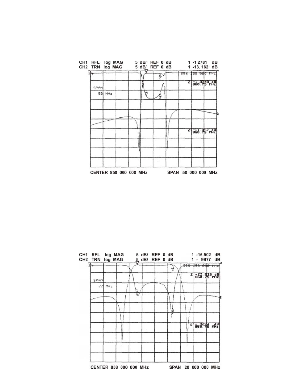
123
Fig. 2
5. Set a SPAN of 20MHz and act alternatively on:
- Interstage couplings 3 (rise and lower);
- IN/OUT couplings 4 (turn);
- Tuning 1 and 2 (rise and lower);
to obtain a bandwidth of 7-8MHz and an adaptation of about 25dB, composed by four peaks (Fig. 3).
Fig. 3
6. Use the coupling 5 (Fig. 1) to set the position of the notch attenuation on the desired frequencies (Fig. 4)
(5.5MHz and +11MHz or 4.5MHz and +9MHz).
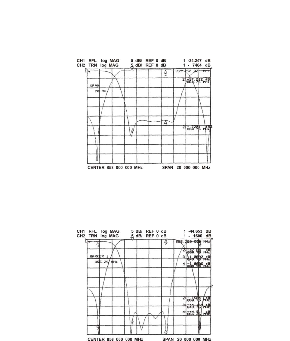
124
Fig. 4
7. It is possible to note that, by tuning the notch attenuation as described in point 6 above, the adaptation has
moved. It can be adjusted by acting on the filter as per point 6, correcting each time the tuning of the notch
attenuation by means of the coupling 5, until a frequency response like the one in the example (Fig. 5) is
obtained.
Fig. 5
8. Once the calibration is complete, the mechanical movement during the locking stage will have to be
compensated for, because a variation of the adaptation may occur. It only takes to extract slightly the tuning
which is being fastened.