Elettronika S r l TXUP5000 TXUP5000 5 kW Analog TV Transmitter User Manual APT120A AUTV 5000LD Rev0 Date221003 p65
Elettronika S.r.l. TXUP5000 5 kW Analog TV Transmitter APT120A AUTV 5000LD Rev0 Date221003 p65
Contents
- 1. User Manual Part 1
- 2. User Manual Part 2
- 3. User Manual Part 3
User Manual Part 1

AUTV/5000LD
LDMOS - UHF TV Solid State Amplifier
Users manual
CODE: APT120A TITLE: AUTV/5000LD REV: 0 DATE: 22/10/03

SS 96 Km 113
70027 Palo del Colle (Ba) ITALY
Tel. +39 (0)80 626755
Fax +39 (0)80 629262
E-mail: elettronika@elettronika.it
Web siste: http://www.elettronika.it
Registration number: IT-17686
Registration number: IT-24436

3
WARNING
The apparatus described in this manual has been designed and manufactured with devices to safe-
guard the users. In any case it is recommended that during any operation of installation, maintenance,
miscellaneous interventions and calibrations requiring the apparatus to be switched on,
THE USER TAKES ALL THE
PRECAUTIONS AGAINST INCIDENTS
It is required to use the proper clothes and protection gloves in order to prevent damages from inci-
dental contacts with high-voltage parts.
The manufacturer declines every responsibility in case the recommendations above are not followed.
IMPORTANT
The component lists attached to the relevant electrical diagrams indicate for each item the reference,
the description and the type normally used.
The Elettronika S.r.l. though reserves the right to use or supply as spare parts components with
equivalent characteristics but of a different type, assuring anyway the optimal work of the apparatus
in accordance with the specifications.
The enclosed monographs are solely owned by Elettronika S.r.l.
The use of anything enclosed in this technical manual without explicit authorization given by Elettronika
S.r.l. will be prosecuted by the law.
The data and technical characteristics of the apparatus described in this manual are not compelling for
the manufacturer.
The Elettronika S.r.l. reserves the right to make, without previous notice, modifications or updates in
order to improve the quality of the product.
The general conditions of supply and sale are described in the contracts.
The delivery time are in accordance with the products and quantities ordered.

4
Summary of warranty
We, ELETTRONIKA S.r.l., SS096 Km 113 Z.I. PALO DEL COLLE (BA) ITALY, warrant to the ORIGINAL PURCHASER of a NEW product, for a
period of one (1) year from the date of purchase by the original purchaser (the warranty period) that the new ELETTRONIKA product is free of defects
in materials and workmanship and will meet or exceed all advertised specifications for such a product. This warranty does not extend to any subsequent
purchaser or user, and automatically terminates upon sale or other disposition of our product.
Items excluded from this ELETTRONIKA warranty
We are not responsible for product failure caused by misuse, accident, or neglect. This warranty does not extend to any product on which the serial
number has been defaced, altered, or removed. It does not cover damage to loads or any other products or accessories resulting from ELETTRONIKA
product failure. It does not cover defects or damage caused by use of unauthorized modificstions, accessories, parts, or service.
What we will do
We will remedy any defect, in material or workmanship (except as excluded), in our sole discretion, by repair, replacement, or refund. If a refund is
elected, then you must make the defective or malfunctioning component available to us free and clear of all liens or other encumbrances. The refund will
be equal to the actual purchase price, not including interest, insurance, closing costs, and other finance charges less a reasonable depreciation on the
product from the date of original purchase. Warranty work can only be performed at our authorized service centers or at our factory. Expenses in
remedying the defect will be borne by ELETTRONIKA, including one-way surface freight shipping costs within the United States. (Purchaser must bear
the expense of shipping the product between any foreign country and the port of entry in the United States and all taxes, duties, and other customs fee(s)
for such foreign shipments).
How to obtain warranty service
You must notify us of your need for warranty service not later than ninety (90) days after the expiration of the warranty period. We will give you an
authorization to return the product for service. All components must be shipped in a factory pack or equivalent which, if needed, may
Desclaimer of consequential and incidental damages
You are not entitled to recover from us any consequential or incidental damages resulting from any defect in our product. This includes any damage
to another product or products resulting from such a defect.
Warranty alterations
No person has the authority to enlarge, or modify this warranty. The warranty is not extended by the lenght of time for which you are deprived of
the use of the product. Repairs and replacement parts are provided under the terms of this warranty shall carry only the unexpired portion of this
warranty.
Design changes
We reserve the right to change the design of any product from time to time without notice and with no obligation to make corresponding changes in
products previously manufactured.
Legal remedies of purchaser
There is no warranty which extends beyond the terms hereof. This written warranty is given in lieu of any oral or implied warranties not contained
herein. We disclaim all implied warranties, including without limitation any warranties of merchantability or fitness for a particular purpose. No action
to enforce this warranty shall be commenced later than ninety (90) days after expiration of the warranty period.
Warranty for electronic tubes
The warranty applied for electronic tubes is the one given by the manufacturer of the tube. In the event that the product shows anomalies within the
deadline of the validity of the warranty given by the manufacturer of the product itself, the buyer will have to return it to the seller with the needed
documents and the written description of the defect. The seller will ship the broken tube to the manufacturer in order to effect the necessary technical
tests to find out the cause of the anomaly. Meanwhile the buyer of the tube who needs to use, and as such to replace immediately the product, will have
to buy a new one and provide to the relevant payment, further to the issuing by the seller of a regular commercial invoice. After the adequate tests made
by the manufacturer, should the result be positive, that is confirm the defect in manufacturing, the seller will issue a regular credit note in the name of
the buyer and return the amount paid. Should the result be negative, that is detect a negligence in the installation or use by the buyer, he will have no
right against the seller.
Warranty

5
INTRODUCTION
The apparatus described in this manual is the latest of this series, offering high performances, remark-
able reliability and a wide range of characteristics, it all at a low cost.
Its is easy to install and use. It only takes to follow the installation procedure as shown in this manual:
after having removed all from the package, you only have to follow step by step the description in the
various sections.
Before starting to use the apparatus, remember to:
read carefully the general safety information contained in this section;
follow the instructions for the installation and set up of the apparatus;
read all the remaining sections of this manual in order to know well the apparatus and learn
how to obtain the best of its characteristics.
CONTENTS OF THE MANUAL
The chapter composing this manual contain all the information concerning the use of the apparatus.
For more information refer to ELETTRONIKA S.r.l.
This manual is made up of different chapters, each made up of various sections. Each individual
chapter represents a single apparatus composing the whole station.

6
WARNING!
The currents and voltages in this equipment are dangerous!
Personnel must at all times observe safety regulation!
This manual is intended as a general guide for trained and qualified personnel who are aware of the
dangers inherent in handling potentially hazaedous electrical and electronic circuits.
It is not intended to contain a complete statement of all safety precautions which should be observed by
personnel in using this or other electronic equipment.
The installation, operation, maintenance and service of this equipment involves risks both to personnel
and equipment, and must be performed only by qualified personnel exercising due care.
Elettronika S.r.l. shall not be responsible for injury or damage resulting from improper procedures or
from the use of improperly trained or inexperienced personnel performing such tasks.
During installation and operation of this equipment, local building codes and fire protection standards
must be observed.
WARNING!
Always disconnect power before opening covers,
doors, enclosures, gates, panels or shields.
Always use grounding nsticks and short out high
voltage points before servicing. Never make
internal adjustments, perform maintenance or
service when alone or when fatigued.
Do not remove, short-circuit or tamper with interlock switches on access covers, doors, enclosures,
gates, panels or shields.
Keep away from live circuits, know your equipment and dont take chances.
WARNING!
In case of emergency ensure that power has been disconnected.

7
A - AIRWAY
If unconscious, open airway lift up neck, push
forehead back, clear out mouth if necessary,
observe for breathing.
Treatment of electrical shock
1) If victim is not responsive follow the A, B, Cs of basic life support.
PLACE VICTIM FLAT ON HIS BACK ON A HARD SURFACE
B - BREATHING
If not breathing, begin artificial breathing. Tilt
head, pinch nostrils, make airttght seal, 4 quick
full breaths. Remember mouth to mouth resuscita-
tion must be commenced as soon as possible.
C - CIRCULATION
Check carotid pulse. If pulse
absent, begin artificial circulation.
Approx. 80sec.: 1 rescuer, 15 compressions, 2 quick breaths.
Approx. 60sec.: 2 rescuers, 5 compressions, 1 breath.
NOTE: DO NOT INTERRUPT RHYTHM OF COMPRESSIONS WHEN
SECOND PERSON IS GIVING BREATH.
Call for medical assistance as soon as possible.

8
2) If victim is responsive:
- keep them warm;
- keep them as quiet as possible;
- loosen their clothing (a reclining position is recommended).
FIRST-AID
Personnel engaged in the installation, operation, maintenance or servicing of this equipment are urged
to become familiar with first-aid theory and practices. The following information is not intended to be
a complete first-aid procedure, it is brief and is only to be used as a reference. It is the duty of all
personnel using the equipment to be prepared to give adequate Emergency First Aid and thereby pre-
vent avoidable loss of life.
TREATMENT OF ELECTRICAL BURNS
1) Extensive burned and broken skin.
- Cover area with clean sheet or cloth (cleansed available cloth article);
- do not break blisters, remove tissure, remove adhered particles of clothing, or apply any salve or
ointment;
- treat victim for shock as required;
- arrange transportation to a hospital as quickly as possible;
- if arms or legs are effected keep them elevated.
NOTE
If medical help will not be available within an hour and the victim is conscious and not vomiting, give
him a weak solution of salt and soda: 1 level teaspoonful of salt and 1/2 level teaspoonful of baking
soda to each quart of water (neither hot or cold).
Allow victim to sip slowly about 4 ounces (half a glass) over a period of 15 minutes.
Discontinue fluid if vomiting occurs (do not give alcohol).
2) Less severe burns - (1st & 2nd degree).
- Apply cool (not ice cold) compresses using the cleansed available cloth article;
- do not break blisters, remove tissue, remove adhered particles of clothing, or apply salve or ointment;
- apply clean dry dressing if necessary;
- treat victim for shock as required;
- arrange transportation to a hospital as qickly as possible;
- if arms or legs are affected keep them elevated.
9
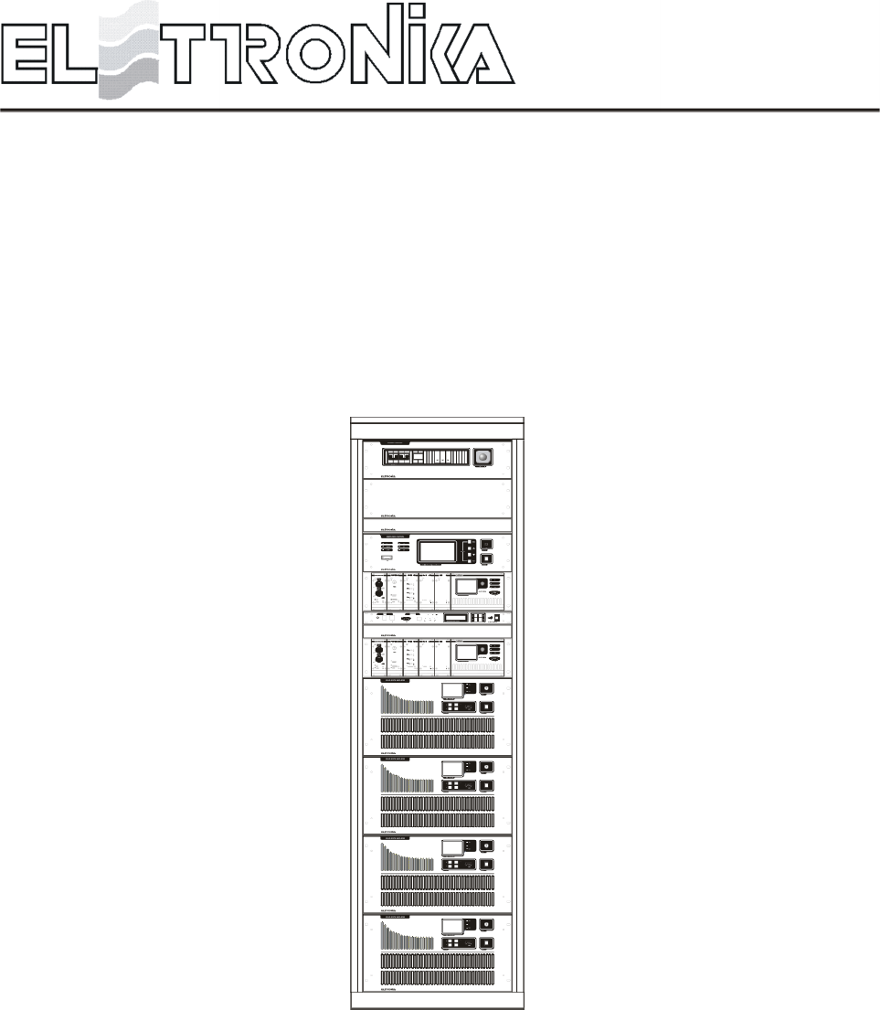
LDMOS - UHF TV AMPLIFIER
AUTV/5000LD
Users manual

10
DESCRIPTION
The AUTV/5000LD belongs to the High Power UHF products family of Television Amplifiers fully in solid
state technology.
The AUTV/5000LD series represents the 5kW TV Amplifier operating in the IV/V Band for Common
amplification process (separate amplification available) of the Vision and Sound carriers. This Transmitters
family has been designed to offer to the customer high performances, high reliability and greater simplicity in
their operation and maintenance procedures.
The Vision and Sound signal processing is provided for all TV Standards and all types of Audio applications
(Mono & Dual sound - NICAM) together with colour systems such as PAL - NTSC - SECAM. Thanks to
the amplitude and phase pre-correction circuit, it is possible to cancel the distortions in the output stage, thus
cutting down the operating costs. The RF transposition in the driver is carried out by a synthesizer with various
possibilities of accuracy and stability as well as precision offset locked by internal or external frequency
reference.
The RF amplifier is made up by four RF modules installed in a power rack, the modules are dedicated for the
Vision and Sound carriers common amplification. The amplifiers employ solid state LDMOS technology in
order to obtain wide band, reliability, and high efficiency. Each RF module has a built-in switching-mode
power supply unit, self-protected against overcurrents and overvoltages, as well as overtemperature and
VSWR for RF parameters. The cooling system is fully contained into the transmitter. The control unit provides
full management of the transmitter without the presence of the operator, the system includes a central controller
and several peripheral units installed in each RF module and rack. Controller and peripherals are connected
by a RS485 full-duplex bus.
Power supply output voltages and currents, forward and reflected power of any single power amplifier are
monitorized by central control unit.
In that way there is a single interface point between user and all the transmitter. The operator interface is made
by a high resolution LCD graphic display and a simple keyboard, the menu is very friendly and easy to use.
The Control Unit can be fully controlled in REMOTE mode via link or via modem in RS232 or other interface.
The equipment design allows the soft degradation (RF power loss) for several transistors faults.
AUTV/5000LD
LDMOS - UHF TV SOLID STATE AMPLIFIER

11
TECHNICAL CHARACTERISTICS
RF SECTION
Frequenchy range ............................................................................................................................................ 470 - 860MHz
Output power .......................................................................................................................................................... 5kW PEP
Vision / Sound power ratio ...................................................................................... 10/1 single sound - 20/1/0.2 dual sound
Out stage technology ............................................................................................................................. Solid State LDMOS
Vision / Sound amplification .................................................................................................................................... Common
Standards ................................................................................................................................................................G, K, I, M
Sound transmission ..................................................................... FM single sound - Dual sound coding IRT - NICAM 728
Harmonics and suppression emission ..................................................................................... In compliance with CCIR rec.
Intermodulation products from vision and sound ................................................................................................... < = 50dB
Frequency stability .........................................................................................................................2,5ppm (option 0,05ppm)
VISION SECTION
Video input ............................................................................................................................................. BNC 75W connector
Nominal input level .............................................................................................................................................. 1Vpp ±6dB
Return loss ............................................................................................................................................................... > = 30dB
DC Restoration ........................................................................... Clamped to the blanking level without affecting the burst
White limiter ................................................................................. At 90% picture signal without affecting the chrominance
Transmission characteristics
Sideband spewctrum response .................................................................................................... According to the standard
Amplitude frequency response....................................................................................................According to the standard
Group delay variation without receiver pre-correction and TV demodulator flat ................................................... < = ±35ns
Non linearity distortion (10 to 75% mod.) ................................................................................................................... < = 5%
Differential gain (10 to 75% mod.) ............................................................................................................................... < = 5%
Differential phase (10 to 75% mod.) ..............................................................................................................................< = 5°
Signal to random noise ratio (weighted 0.2 to 5MHz) .............................................................................................. > = 60dB
Blanking level variation............................................................................................................................................... < = 2%
2T k factor ................................................................................................................................................................... < = 2%
SOUND SECTION
Nominal input level (±50kHz dev.) ..................................................................................................................... -10 to +8dBm
Input impedance ............................................................................................................................................ 600W balanced
Pre-emphasis .................................................................................................................................................................. 50ms
Transmission characteristics
Amplitude frequency response............................................................................................................ 40 to 15000Hz ±0.5dB
Total harmonic distortion ......................................................................................................................................... < = 0.5%
FM Signal to noise ratio (referred to ±50kHz dev. f = 400Hz) ................................................................. > = 60dB (weighted)
AM Signal to nokise ratio .......................................................................................................... > = 50dB (referred to 100%)
AM Synchronous modulation ................................................................................................... < = 40dB (referred to 100%)
REMOTE CONTROL
Parallel interface ............................................................................................................................. On/Off, Alarms, Interlock
Serial interface ....................................................................................... RS232 or RS485 (Full monitoring and management)

12
GENERAL
Power supply voltage ................................................................................................... 3x380VAC, ±10% (other on request)
Frequency ........................................................................................................................................................ 50-60Hz, ±5%
Temperature operating range .................................................................................................................................. 0 to 45°C
Altitude ...............................................................................Up to 2.500 meters (> = 2.500m with additional cooling system)
Power consumption (cooling system included) .................................................................................< = 12kVA (black level)
Power factor ................................................................................................................................................................ > = 0.9
Cooling .................................................................................................................................................................. Forced air
Dimensions ...................................................................................................................................................... Rack 19-42U
13
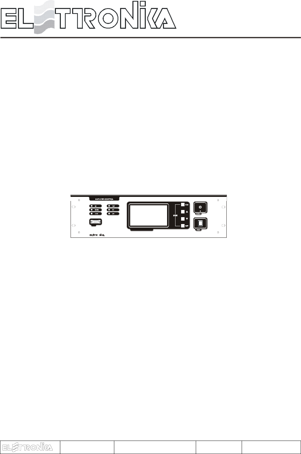
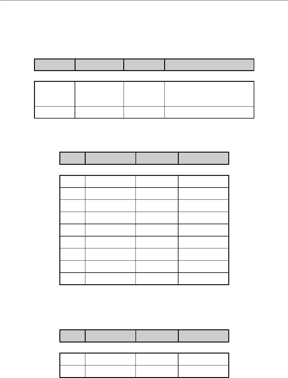
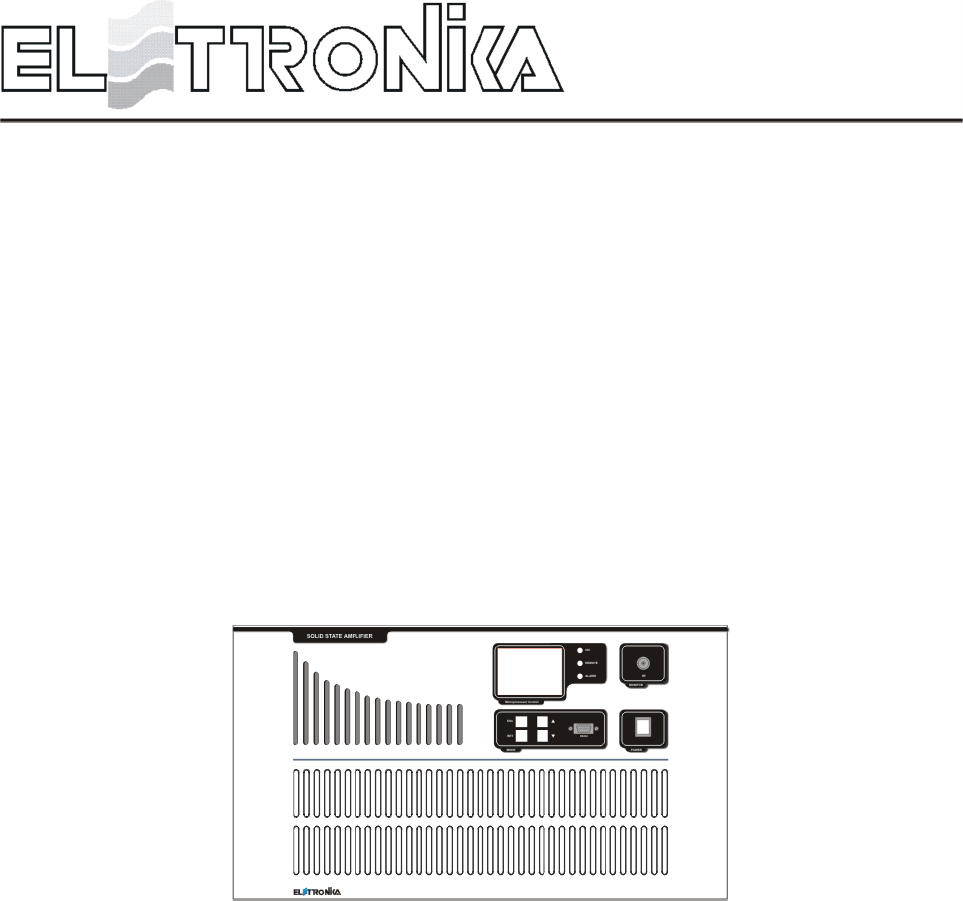
AMPLIFIER CONTROL
O
MICROPROC ESSOR CONTROLL ED SYST EM
RS2 32
CODE: APG012C TITLE: AMPLIFIER CONTROL REV: 1 DATE: 10/02/04
14
1.1 CONTROL SYSTEM OVERVIEW
The control system is made up by some Slave boards, which check locally the amplifier modules, and a
Master board to monitor the status of the Slave boards in each module and show on a graphic display all
the checked parameters.
The number of the Slaves changes depending on the output power of the amplifier. The communication
between Master and Slaves is made via RS485 standard. The Master board reads the overall parameters of
the equipment (Forward and Reflected power and Unbalancing), polls (interrogaes in sequence) the local
boards, shows on the display the values requested by the user, indicates alarm conditions, if any, and allows
to change some of the operating parameters of the apparatus. Besides it realizes a serial data interface to an
external system able to analyse the working parameters of the equipment, using the RS232 and RS485
communication protocols.
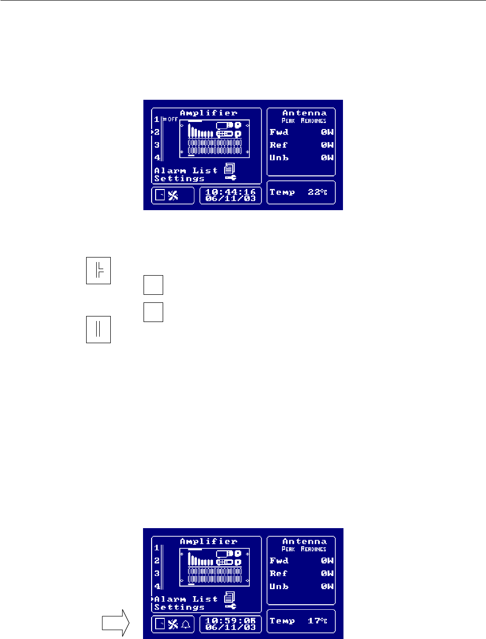
1.2 FUNCTIONS
At start-up, the display of Amplifier Control module shows an informational message concerning the equipment
and its firmware version.
- Main menu
The main menu has: a list of the amplifier modules, the measure of some parameters of the power in antenna,
a window with icons to show the alarm status (Alarm Status Window) and some general information, that is
date, time, temperature inside the module and, for FM equipment, transmission frequency.
The following picture is an exact representation of the main menu screen.
AMPLIFIER CONTROL
O
MICROPROCESSOR CONTROLLED SYSTEM
RS2 3 2
15
if the communication with the slave is correct and then
if the communication with the slave is interrupted
ON
if the amplifier module is OFF
OFF
if the amplifier module is ON
In the Amplifier List, next to each module, the following symbols can be found:
The UP and DOWN arrow keys allow to select one of the slave, the alarm list, or a menu allowing to change
some settings of the control module and the apparatus; the RET key is used to confirm the selection.
In the main and slave menu the Alarm Status Window (which position is indicated by an arrow in the picture
below) is shown: the gate symbol displays the status of the INTERLOCK, in case of alarm this icon blinks
and the buzzer ringgs.
The INTERLOCK signal is a control available to the user to manage an ON/OFF sensor.
When the relevant PIN is grounded, the Master board does not signal any alarm, as soon as the PIN is left
floating, an alarm is detected; the rotating screw symbol shows that the FANS work normally; in case of alarm
this icon blinks and the buzzer rings; the bell symbol appears in case of alarm detected by the control module
or the amplifier. It blinks if the alarm condition is terminated and the alarm itself can be displayed in the Alarm
List.
If one of the parameters of a Slave or any of the ones directly checked by the Master is alarmed, the general
16
Note that no numerical value is shown for amplifiers which are not communicating with the control module.
alarm LED and the alarm icon blink until the Alarm List is checked to see the type of alarm occurred.
Besides, if an alarm for any of the powers of the signals in antenna occurs, the relevant measure in the
Antenna window of the display and the relevant LED on the front panel of the Master module blink until the
measure decreases below the threshold level, determined by the nominal power of the amplifier.
If the slave modules are working and an INTERLOCK or FANS alarm occurs, aside from the indication
explained above, the amplifiers are switched off. This happens immediately after an INTERLOCK alarm, or
about 7 seconds after a FANS alarm is detected.
In case the amplifiers are communicating but switched off, or they are not communicating and the INTERLOCK
alarm contact is open, a WARNING condition occurs: buzzer on and blinking ALARM LED on the front
panel; while if it is the FANS alarm contact to be open, the icon of the alarm appears in the box.
Further to any of these two alarms it is possible to choose whether to turn off the amplifiers or not. In fact,
there is a submenu of the Settings menu which allows to choose whether to turn off the amplifiers connected
to the control module as a consequence of an INTERLOCK and FAN alarm.
- Slave menu
By selecting one of the slaves, it is possible to see all the parameters of that amplifier module in two pages. The
first one shows voltages and currents Power Supply, the second one shows RF Powers: forward and reflected
power, temperature and, for some amplifiers, unbalancing and input power. The UP and DOWN keys allow
to scroll the local measures of all the slaves, page by page. The ESC key is used to go back to the main menu.
The following pictures show the menu screen of one amplifier.
17
- Alarm List
By selecting the Alarm List, 26 pages listing the latest 130 alarms saved are shown. Each page shows 5
alarms, each contained in a box providing the following information: progressive number of the alarm, starting
with the most recent; number of the module in which the alarm occurred, following the Blk. Message (the
indication AC means that the alarm occurred in the Amplifier Control module); parameter in alarm, date and
time of the alarm. Next to the parameter showing the alarm type there may be a bell symbol. In case it is not
here, the alarm event has been communicated by an amplifier connected to the control module. These events
are different and on option of the Settings menu allows to choose whether they are displayed or not in the
alarm list.
The saved alarm can be deleted by keeping simultaneously pressed the UP and DOWN keys. The ESC key
is used to go back to the main menu. The picture shows a page of the list, containing both alarms and general
events.
1.3 PROGRAMMING MODE
The Settings menu gives access to programming mode. As shown below, the menu offers a list of settings next
to a window showing the default parameter set, or the one selected previously, when the pointer is moved on
the relevant options.
The menu under the cursor is accessed by pressing the RET key. This is shown by the Enabled Menu. Once
18
Description of the submenus included in Settings.
SUBMENU OPERATION
Update the time and date shown in the main menu box.
Selection of the analogue voltage signal (PEAK or RMS) to convert and
display the Forward power in antenna. A message in the main menu screen
confirms current choice.
It is possible to remotely control the apparatus, thus to monitor the parameters
shown on the display of Amplifier Control module and check the status of the
transmitter.
This is done through RS232 or RS485 standard serial communication, digital
and analog inputs through the DB25 telemetering connector on the rear panel
of the Amplifier Control module.
If the Local mode is set in this menu, the control module and the apparatus
can only be controlled locally, and a remote command is ignored. If Remote
is set instead, the REMOTE LED on the front panel of the module lights up
after going back to the main screen. From then on, incoming remote commands
from either the serial port or the telemeasuring connector on the rear panel
are handled (Note 1).
Clock / Date
FWD Read Mode
Remote Control
the menu is accessed, it is possible to change the value of the displayed fields or select a function by means of
the arrow keys. The RET key is used to confirm the selection (an acoustic signal should be heard). The ESC
key (or no key pressed for more than 7 seconds) sends back to the setting list. Pressing it again (or pressing
no key for more than 10 seconds) brings back to the main menu.
Every selection made in the Settings menu is stored into the EEPROM until it is changed again, this allows to
remember the settings status after an equipment reset.

19
Serial Comm
Buzzer
FAN Alarm
INT Alarm
LOG Mode
Working Timer
Backlight
Frequency
Thresholds info
Release info
Note 1: to control the apparatus from remote, consider that pins n. 1 and n. 14 of the telemetering connector on the rear panel
of Amplifier Control module are used to receive the ON (pin n. 1) and OFF (pin n. 14) commands, both impulsive and
stationary. The digital level on these contacts is usually high, becoming low when the remote control is active. When a remote
command to turn off the amplifiers is received while the transmitters is ON, the LED ON of the frontal panel blinks.
Selects the remote control via serial port.
RS232 MODE: the RS232 mode allows a direct access to the equipment
via PC and a remote access via modem or switched telephone line.
RS485 MODE: the RS485 mode allows a remote access to the equipment
via modem over switched telephone line or GSM network. It allows the
connection to the Remote Control System, designed to monitor several
apparatuses located at the same site.
Enables / disables the buzzer during normal operation.
Select OFF to have the amplifiers turned off further to a FAN alarm; if
ON is selected, they will stay on.
Select OFF to have the amplifiers turned off further to a INTERLOCK
alarm; if ON is selected, they will stay on.
Select only alarms to store in the EEPROM and display in the module LOG
only detected alarms; select all events to store and display also any event
detected by any amplifier and sent via RS485 to the control module.
Updates the counter of the working time of the transmitter. Once this menu
has been enabled, the counter reset option appears in the window.
If Switch Off is selected and no key is pressed for 8 minutes, the back light
of the display is turned off; select always ON to have it always on.
This menu only exists in the firmware for Amplifier Control of FM transmitters.
The working frequency can be selected within a range from 88 to 108MHz,
this allows to optimise the display of the Forward power sent to the antenna.
Shows for some seconds the alarms thresholds of the powers sent to the
antenna.
Shows for some seconds information concerning the transmitter and the
firmware version.

20
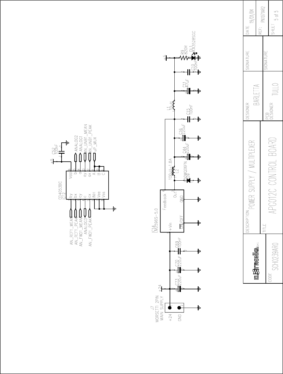
1.3 POWER CALIBRATION
- FWD Power calibration
Disconnect the antenna and connect a wattmeter to the antenna connector. Give power to the amplifier until
you will read on the wattmeter a value corresponding to the equipment nominal power. Then turn the trimmer
A (see mounting plan BOTTOM - PN1071AR2, it is a variable resistor used to adjust the A analog input
measure) until you read approximately the same FWD power value on the display.
- REF Power calibration
Disconnect the antenna and connect a wattmeter to the antenna connector. Connect the Forward power
monitoring cable to the Reflected power input connector. Give power to the amplifier until you will read on the
wattmeter a value corresponding to 10% of the equipment nominal power. Then turn the trimmer B (see
mounting plan BOTTOM - PN1071AR2, it is a variable resistor used to adjust the B analog input measure)
until you read approximately the same REF power value on the display.
- UNB Calibration
Connect a wattmeter before the dummy load. Give power to the amplifier then turn off one slave module: you
will read an amount of unbalancing power on the wattmeter. Turn the trimmer C (see mounting plan BOTTOM
- PN1071AR2, it is a variable resistor used to adjust the C analog input measure) until you read approximately
the same UNB power value on the display.
1.4 RS232 AND RS485 PIN TABLES
PIN N° SYGNAL TYPE IN/OUT FUNCTION
1- - -
2 Digital Input RX2_485B-
3 Digital Input RX2_485A+
4- - -
5GND - -
6- - -
7 Digital Output TX2_485Z-
8 Digital Output TX2_485Y+
9- - -
PIN N° SYGNAL TYPE IN/OUT FUNCTION
1- - -
2 Digital Output TX232
3 Digital Input RX232
4- - -
5GND - -
6 VDC +5V - -
7- - -
8- - -
9- - -
RS232 - DB9 Connector (Front panel) RS485 - DB9 Connector (Rear panel)

21
1.5 TELEMEASURING PINS TABLE
PIN N° SIGNAL TYPE IN / OUT FUNCTION
1 Digital -
REMOTE ON/OFF TTL:
GND = REMOTE ON
+5V = REMOTE OFF
2 Digital Output -
3 Digital Output -
4 Digital Output -
5 Digital Output -
6 Digital Output -
7 Digital Output AGC alarm TTL:
GND = AGC alarm, +5V = no AGC alarm
8 Digital Output -
9GND - -
10 Analog Output -
11 Analog Output -
12 Analog Output -
13 Analog Output -
14 Digital Input
REMOTE AMPLIFIER ON/OFF TTL:
if REMOTE ON then
GND = AMPLIFIER OFF
+5V = AMPLIFIER ON
15 Digital Output -
16 Digital Output -
17 Digital Output -
18 Digital Output -
19 Digital Output AGC alarm TTL:
GND = AGC alarm, +5V = no AGC alarm
20 GND - -
21 +5V - -
22 Analog Output FWD Power [0,+ 5V]
23 Analog Output REF Power [0,+ 5V]
24 Analog Output UNB Power [0,+ 5V]
25 Analog Output -
22
1.6 OTHER TABLES
BNC Connectors
AGC Connector
SYGNAL TYPE IN/OUT FUNCTION
A Analog Input FWD Power monitoring
B Analog Input REF Power monitoring
C Analog Input UNB Power monitoring
D- - -
E- - -
F- - -
G- - -
PIN N° SYGNAL TYPE IN/OUT FUNCTION
1GND - -
2 Digital Output AGC alarm TTL:
GND = AGC alarm, +5V = no AGC alarm
3 Digital Output AGC alarm TTL:
GND = AGC alarm, +5V = no AGC alarm
4- - -
5- - -
6- - -
7- - -
8 Analog Output FWD Power (range 0 - +5V)
9 Analog Output FWD Power (range 0 - +5V)
23
BNC SYGNAL TYPE IN/OUT FUNCTION
Contact Digital Input
FANS control Switch or TTL:
closed/GND = no FANS alarm
open/+5V = FANS alarm
Body GND - -
FANS CONTROL Connector
PIN N° SYGNAL TYPE IN/OUT FUNCTION
1- - -
2 Digital Output TX1_485Z-
3 Digital Output TX1_485Y-
4- - -
5GND - -
6- - -
7 Digital Input RX1_485B-
8 Digital Input RX1_485A+
9- - -
RS485 - DB9 Connector (Amplifiers communication)
PIN N° SYGNAL TYPE IN/OUT FUNCTION
1GND - -
2 VDC +24V - -
24VDC LOAD FAN Connector
24
O
MICROPROCESSOR CO NTROLL ED SYSTEM
RS 2 32
Front panel
1
34
5
6
7
2
DESCRIPTION
1Status LEDs
2Alarm LEDs
3 RS232 Socket
4 LCD Display
5 Function keys
6 RF Monitor connector
7ON/OFF Switch
25
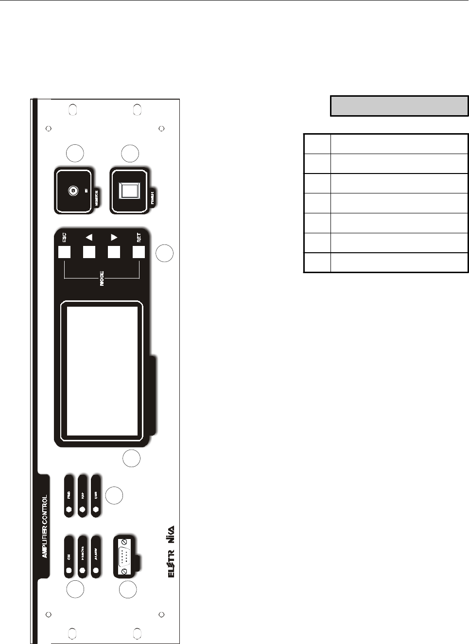
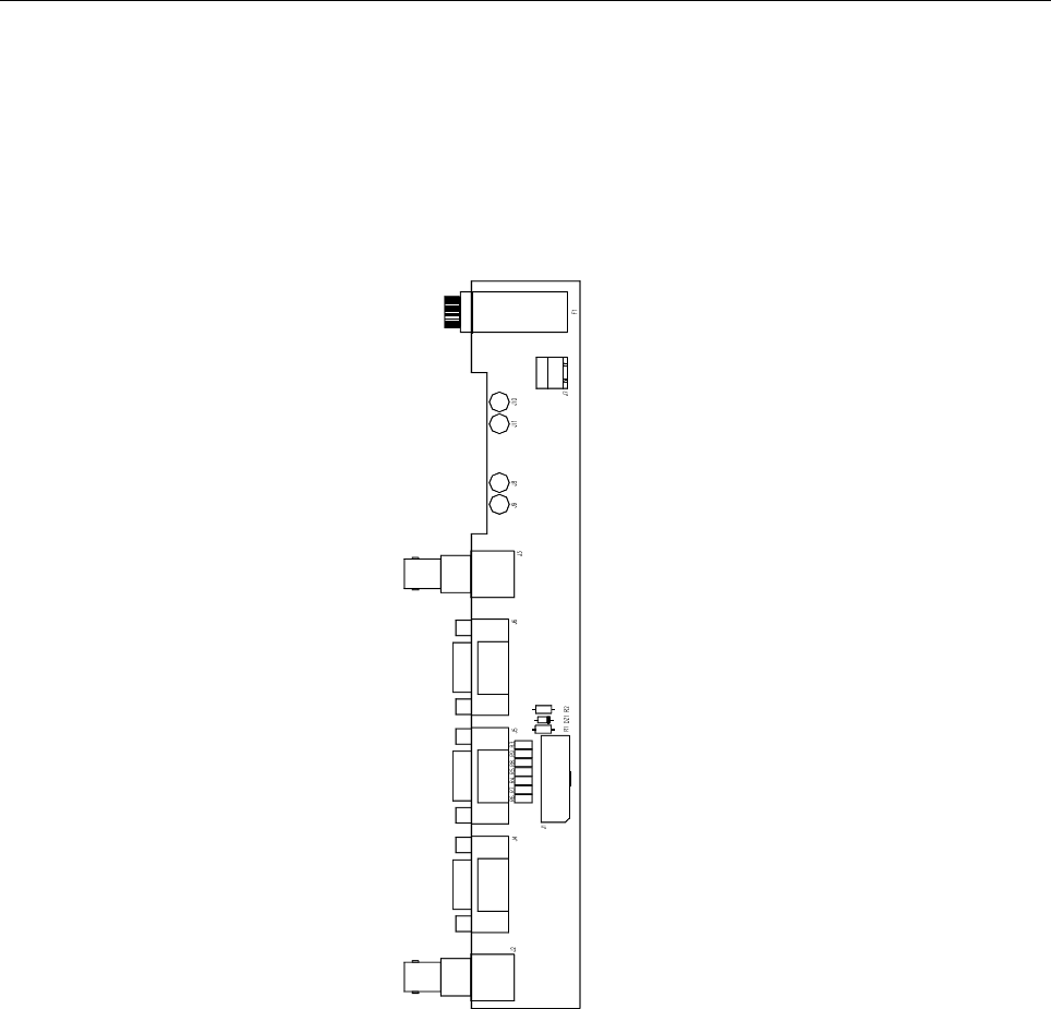
Rear panel
1
2
3 4 5
6
7
816
9 12 13 14 15
10 11
DESCRIPTION
1 RF Input connector
2 Main Power supply socket with Fuse-Holder by 10A
3 Driver1 Power socket
4 Driver2 Power socket
5 Fans Power socket
6GND
7 Fuse by 1A
8 Fuse by 8A
9 24Vdc Connectors
10 AGC Socket
11 Telemeasures socket
12 Fans Control connector
13 RS485 Socket (Amplifiers Communication)
14 RS485 Socket (Remote Control)
15 Interlock connector
16 Power measurement connector

26
Part Name Code Description Qty
CON0145 CON0145R0 POST. CASS. CONTROLLO APG012B 1
05504 CON0134R0 PIANO PROF. 260 ARE. p. 02047 ZN 1
05525 LAT. 3U PROF. 260 TAV. 424/A p. 2033 ZN 2
PAN0066 PAN0066R0 PANNELLO CONTR. APG012B 3U 1
CON0153 CON0153AR0 BASE CASS. CONTR. x APG012 ZN 1
0552B KIT MANIGLIE 3-4U cod. 235.012 2
02880 SPINA V.DE 10A + INT. + FUS. DA PANN. BZ15011 1
SCH0239AR0 SCHEDA DI CONTROLLO CON DISPLAY 1
SCH0110BR0 SCHEDA 3 IN. ANALOGICI MASTER APG012B 1
SCH0152AR0 SCHEDA COMMUTAZIONE 220VAC x APG012B 1
SCH0241AR0 SCHEDA IN/OUT DIGITAL SIGNAL FOR APG012C 1
E0031 ALIM. SWITCHING S-60-24 1
07926 PROTEZIONE IN GOMMA PVC PG 087 1
02843 SPINA SCHERM. 2 POLI cod. 525.2552 1
02695 CONNETTORE DB9F x CAVO IU008059 1
02856 CONNETTORE DB25F x CAVO 525-2812 1
07925 PROTEZIONE IN GOMMA PVC PG075 1
07524A INTERR. NERI I3910 1
02018 GE 35145D/22 BN(UG909/cxRG174) 1
02035 PRESA BNC/F x RG316 cod. 60140 1
08500 CAVO RG174 50W0,30
02700 CONNETTORE cod. 534-2303 FEM. 16 VIE 1
02790 CONNETTORE DB25M x CAVO SALDATO 525-2602 1
02871A CALOTTE PER DB25 cod. 525-2622 1
C0814 NASTRO CONDUT. IN RAME DA 25mm 264/9275 0,50
V0761 TAPPI NERI O 12.7 PLASTICA DP-500 5
Component list APG012C - Amplifier Control

27
This page is intentionally blank
28
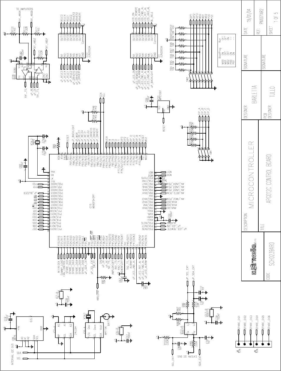
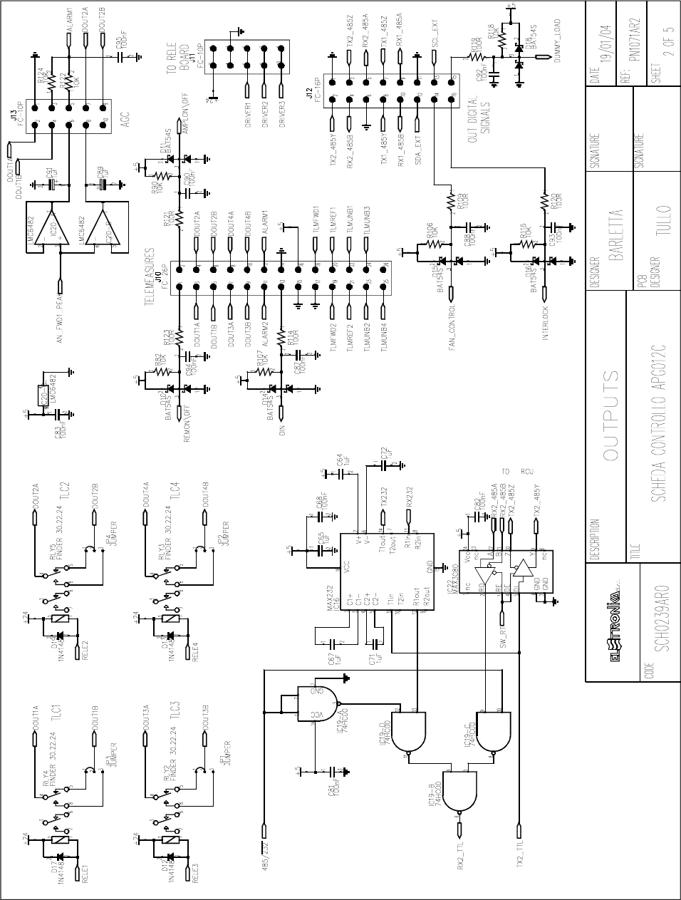
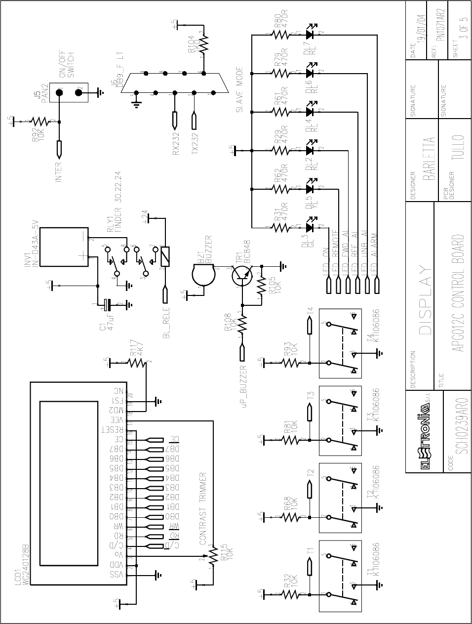
CONTROL AND DISPLAY BOARD SCH0239AR0
Component layout SCH0239AR0 (Bottom and Top layer)
29
30
31
32
33

34
COMPONENT LIST SCH0239AR0
Part Name/Number Description Qty. Comps. Page 1/2
BATT BH001RB 3093_90 03093 03090 BATTERY HOLDER 1 BATT1
BZ AI-155 03705 03705 5VDC BUZZER 1 BZ1
CC 100nF-S 01065C 01065C Y5V 1206 COND 33 C10, C15, C17-19, C22, C25, C28, C38,
C45, C49-52, C55, C62-63, C68-69, C78,
C80-85, C87-88, C90, C92-95
CC 15pF-S 01088 01088 SMD 1206 COND 2 C74-75
CC 1nF-S 01096 01096 SMD 1206 COND 20 C12-14, C31-33, C42-43, C53-54, C56-58,
C60-61, C66, C76-77, C79, C86
CC 1uF100V-S 01760A 01760A Y5V 1206 COND <<50 V>> 8 C21, C23, C37, C64-65, C67, C71-72
CC 220pF-S 01093 01093 SMD 1206 COND 8 C2-9
CC 47pF-S 01100 01100 SMD 1206 COND 8 C20, C30, C35-36, C40-41, C48, C59
CE 10uF16V-S 01626B TANT. ELETTR SMD CO 8 C24, C26-27, C29, C34, C39, C46-47
CE 1uF50V-S 01763A 01763A ELETTR SMD COND 2 C89, C91
CE 220uF50V LOW ESR 1799A ELETTR SMD COND LOW ESR 4 C16, C44, C70, C73
CE 47uF35V-S 01790A 01790A ELETTR SMD COND 1 C11
CE 47uF50V-S 01791C 01791C ELETTR SMD COND 1 C1
D 1N4148-S 03002 03002 SMD DIODE 4 D12-13, D17, D19
D 50WQ06FN 03019A SMD DIODE SCHOTTKY 5,5A 1 D9
D BAS85-S 03024 SMD DIODE SCHOTTKY 8 D1-8
D BAT54S 03199 SMD SCHOTTKY DIODE A-K T 6 D10-11, D14-16, D18
DIS WG240128B 03083 240/128 DOT MATRIX LCD 1 LCD1
DL KA-3528SGC 03057 03057 GREEN SMD LED DIODE 1 DL1
DL LEDG3 03053 03053 GREEN LED DIODE 3mm 1 DL3
DL LEDR3 03058 03058 RED LED DIODE 3mm 4 DL2, DL4, DL6-7
DL LEDY3 03051 03051 YELLOW LED DIODE 3mm 1 DL5
IC 24LC64 04815 04815 SMD INTEG CIRCUIT 1 IC7
IC 74HC00-S 4762A 4762A SMD INTEG CIRCUIT 1 IC19
IC 82B715-S 04734A 04734A SMD INTEG CIRCUIT 1 IC17
IC CD4053BC-S 04710A 04710A SMD INTEG CIRCUIT 1 IC12
IC LM2596S-5.0 04580 SMD INTEG CIRCUIT 1 IC14
IC LM75-S 00668 00668 SMD INTEG CIRCUIT 1 IC8
IC LMC6482-S 04632 SMD INTEG CIRCUIT 1 IC20
IC LMC6484-S 04634 SMD INTEG CIRCUIT 4 IC2-5
IC M41T56 04611 04611 SMD INTEG CIRCUIT 1 IC6
IC MAX232-S 04804B 04804B SMD INTEG CIRCUIT 1 IC16
IC MAX3080-S 04770 04770 SMD INTEG CIRCUIT 1 IC22
IC MAX3080-S N.M. NOT MOUTED SMD INTEG CIRCUIT 1 IC18
IC MAX942CSA-S 04572 SMD INTEG CIRCUIT 4 IC9-11, IC13
IC MB90F543PF 04596 SMD INTEG CIRCUIT 1 IC15
IC MPC100T-450I-TT 04577 SMD INTEG CIRCUIT 1 IC21
IC ULN2003A 4870 04870 SMD INTEG CIRCUIT 2 IC1, IC23
IND MS85 10uH-S 04948 INDUCTOR 2,7A 1 L1
IND T100uH-1.8A 4958 04958 TOROIDAL-STORAGE CHOKES 1 L2

35
Part Name/Number Description Qty. Comps. Page 2/2
INV IN-D43A-5V 03085 DC/AC MODULE 1 INV1
J DB9_F-0° LT 02794 PCB CONNECTOR DB9 LONG T 1 J6
J FC-10P 02697-02699 02697+02699 PCB CONNECTOR POL 2 J11, J13
J FC-16P 02701-02700 02701+02700 PCB CONNECTOR POL 2 J12, J14
J FC-26P 02855-02854 02855+02854 PCB CONNECTOR POL 1 J10
J PAN2 02739 02739 PCB CONNECTOR 1 J4
J PAN2 02739-40-41 02739+02740+02741 PCB CONNECTO 1 J5
J PAN3 02707 02707 PCB CONNECTOR 3 J1-3
J PAN3 NOT MOUNTED NOT MOUNTED PCB CONNECTOR 2 J8-9
J SCREWCONN2 02853 02853 PCB SCREW CONNECTOR 1 J7
JU JUMP3 02707-02742 02707+02742 MASCHIO PAN3 4 JP1-4
R 100R-S 00029A 00029A RES 1/4W 5% SMD 1206 6 R109, R114, R119-121, R123
R 10K-S 00053A 00053A RES 1/4W 5% SMD 1206 37 R22-27, R30, R32-33, R40, R47, R50, R57,
R68, R81-82, R85, R90-101, R105-108,
R116, R118, R122, R124
R 120R-S 00030A 00030A RES 1/4W 5% SMD 1206 2 R112-113
R 1K0-S 00041A 00041A RES 1/4W 5% SMD 1206 5 R46, R54, R87-88, R104
R 1K5-S 00043A 00043A RES 1/4W 5% SMD 1206 2 R110-111
R 22K-S 00057A 00057A RES 1/4W 5% SMD 1206 11 R18, R20-21, R28, R34, R36, R38-39, R41,
R43-44
R 2K2-S 00045A 00045A RES 1/4W 5% SMD 1206 8 R19, R35, R37, R42, R45, R53, R59-60
R 330R-S 00035B 00035B RES 1/4W 5% SMD 1206 2 R89, R103
R 33R-S 00023A 00023A RES 1/4W 5% SMD 1206 2 R86, R102
R 470K-S 00073A 00073A RES 1/4W 5% SMD 1206 8 R48-49, R51-52, R55-56, R58, R65
R 470R-S 00037A 00037A RES 1/4W 5% SMD 1206 30 R10-17, R29, R31, R61-64, R66-67,
R69-80, R83-84
R 4K7-S 00049A 00049A RES 1/4W 5% SMD 1206 1 R117
R 820R-S 00040A 00040A RES 1/4W 5% SMD 1206 1 R9
RL 30.22.24 07569 07569 RELE 5 RLY1-5
RV 10K-S-H 00715 00715 VARIABLE RESISTOR 1 R115
RV 1M-3266X 00815 VARIABLE RESISTOR 8 R1-8
SW SWITCH-4DIP 90° 07531A PCB DIP SWITCH 90° 1 SW1
SW SWITCH-8DIP 07530A PCB DIP SWITCH SMD 1 SW2
T 06086 N 7630 7632 7630 7632 KTI06086 PULSANTE 2 4 T1-4
TR BC848 03457 03457 NPN SMD TRANSISTOR 1 TR1
XTAL 32.768k-S 05146 05146 QUARTZ 1 XTAL1
XTAL 4MHz-S 05101A 05101A QUARTZ 1 XTAL2
36
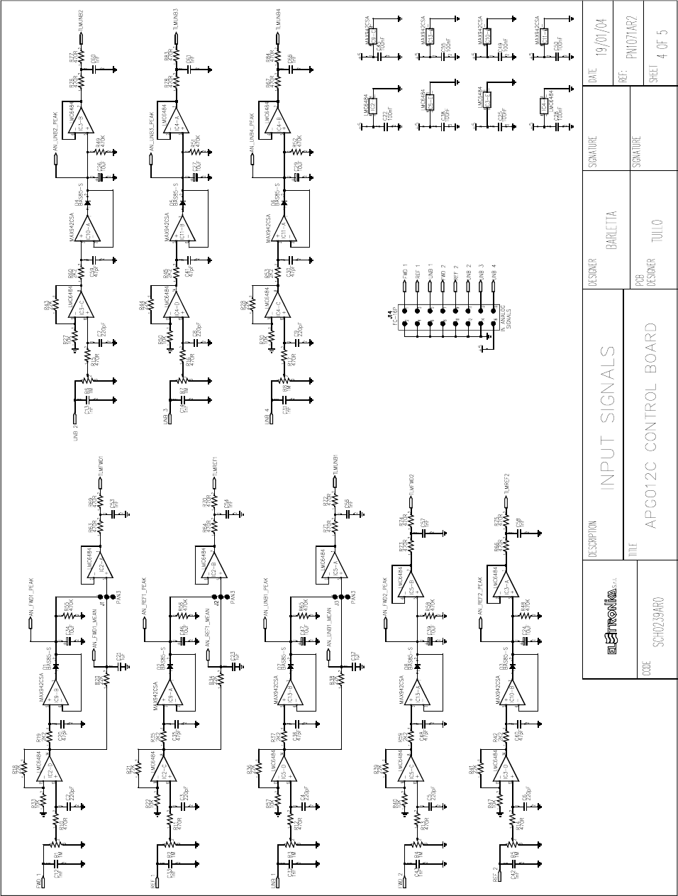
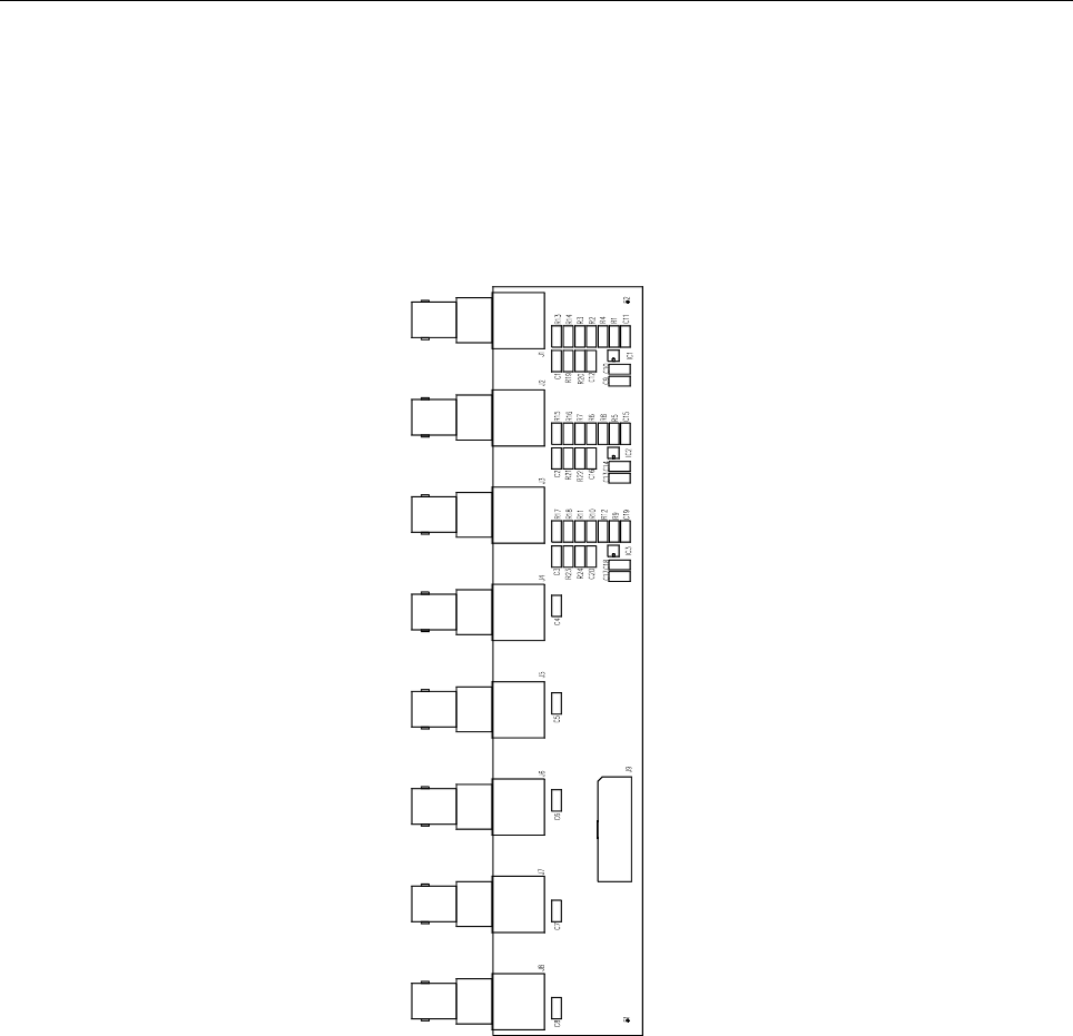
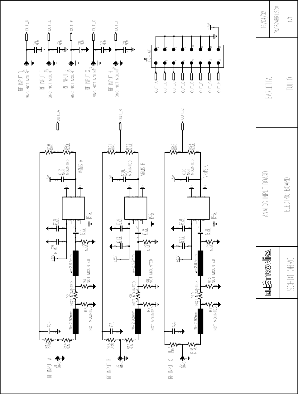
ANALOG INPUT BOARD SCH0110BR0
Component layout SCH0110BR0
COMPONENT LIST SCH0110BR0
Part Name/Number Description Qty. Comps.
CC 1206 N.M. N.M. SMD 1206 COND 17 C4-20
CC 1nF-S 01096 01096 SMD 1206 COND 3 C1-3
J BNC-90G-PCB 2034 02034 PCB CONNECTOR 3 J1-3
J BNC-90G-PCB 2034 N.M. BNC-90G 5 J4-8
J FC-16P 02701-02700 02701+02700 PCB CONNECTOR POL 1 J9
R 0R0-S 00001 00001 RES 1/4W 5% SMD 1206 6 R13, R15, R17, R19, R21, R23
R 1206 N.M. N.M. RES 1/4W 5% SMD 1206 18 R1-12, R14, R16, R18, R20, R22
R24
Z MICRO SOIC 8P N.M. SMD INTEG CIRCUIT NOT MOUNTED 3 IC1-3
37
38
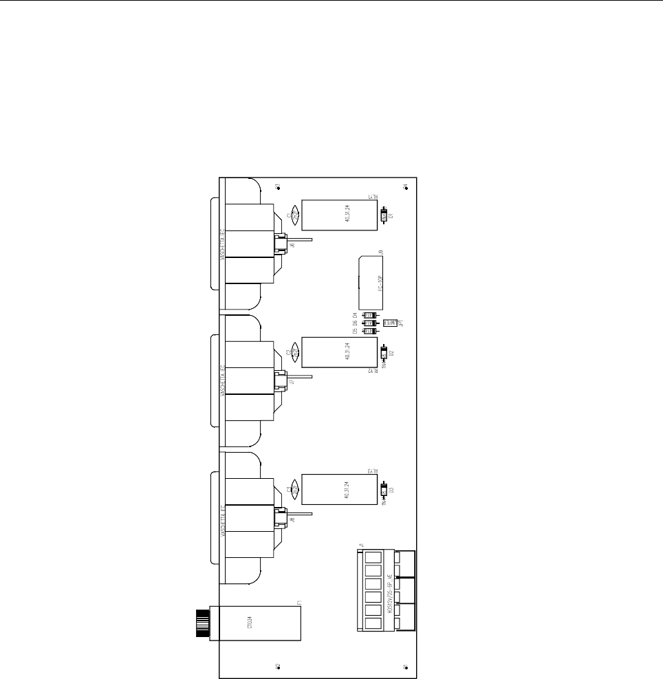
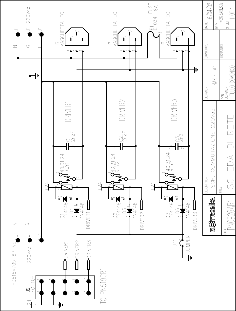
220VAC SWITCHING BOARD SCH0152AR0
Component layout SCH0152AR0
COMPONENT LIST SCH0152AR0
Part Name/Number Description Qty. Comps.
CC 2nF2 2kV 01045A 01045A CERAMIC COND 3 C1-3
D 1N4148 03001 03001 DIODE 6 D1-6
FUSE OMEGA C1034 FUS00008 PORTA FUSIBILE 5x20 D 1 F1
J CON HD515V/05-6PVE 02883 + 02884 PANDUIT PCB CONN 1 J1
J FC-10P 02697-02699 02697+02699 PCB CONNECTOR POL 1 J9
J VASCHETTA IEC 02879 VASCHETTA FEMALE PCB 3 J6-8
JU JUMP2 02739-02742 02739+02742 MASCHIO PAN2 1 JP1
RL 40.31.24 7567C RELE 3 RLY1-3
39
40
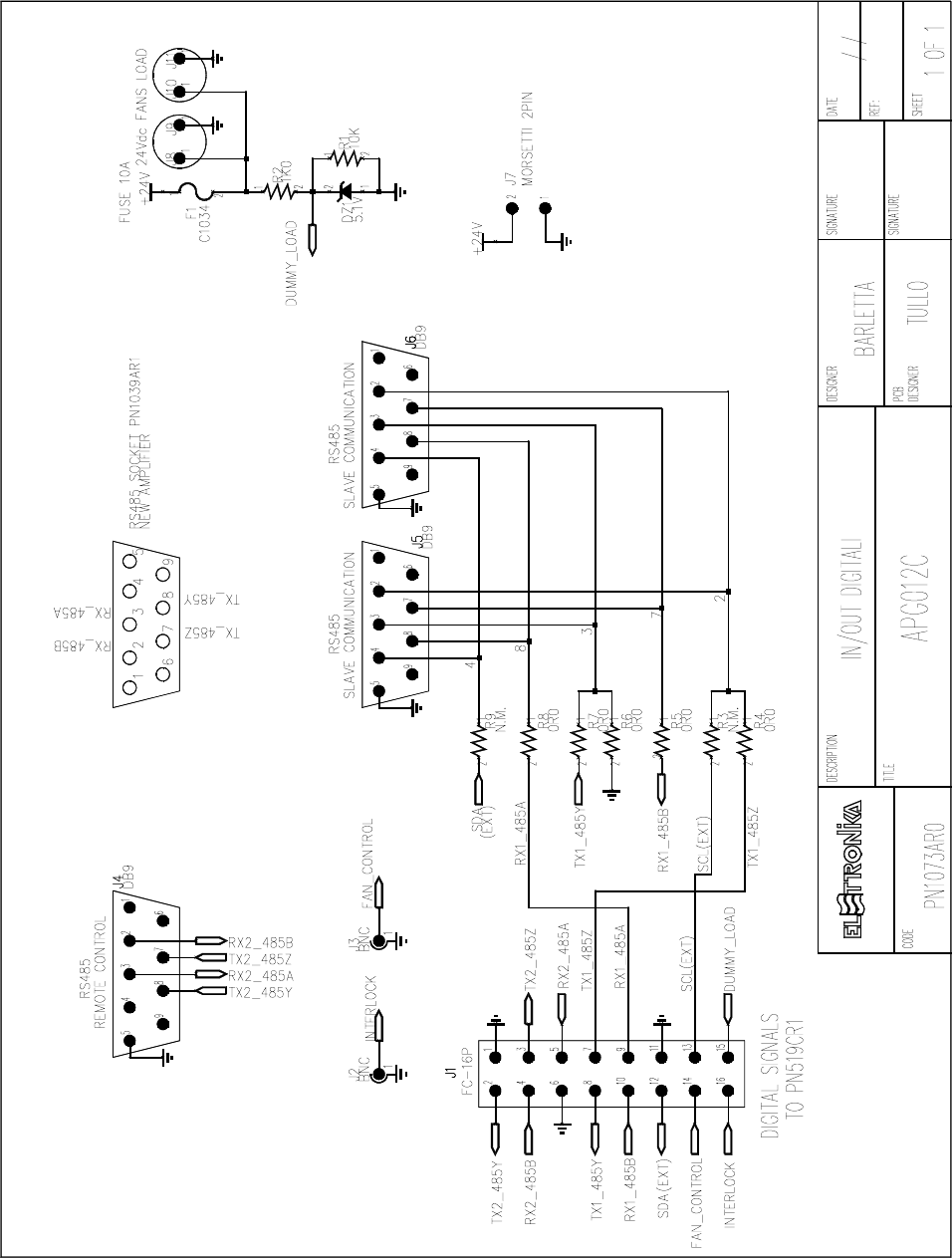
IN/OUT DIGITAL BOARD SCH0241AR0
Component layout SCH0241AR0
COMPONENT LIST SCH0241AR0
Part Name/Number Description Qty. Comps.
DZ 5V1 03109 03109 ZENER DIODE 1 DZ1
FUSE OMEGA C1034 FUS00008 PORTA FUSIBILE 5x20 D 1 F1
J BNC-90G-PCB 2034 02034 PCB CONNECTOR 2 J2-3
J DB9-90G 02797 02797 PCB CONNECTOR 3 J4-6
J FC-16P 02701-02700 02701+02700 PCB CONNECTOR POL 1 J1
J SCREWCONN2 02853 02853 PCB SCREW CONNECTOR 1 J7
J TESTP2.5mm 07912 07912 TEST POINT 4 J8-11
R 0R0-S 00001 00001 RES 1/4W 5% SMD 1206 7 R3-9
R 10K 0053 0053 RES 1/4W 5% 1 R1
R 1K0 0041 0041 RES 1/4W 5% 1 R2
41

42
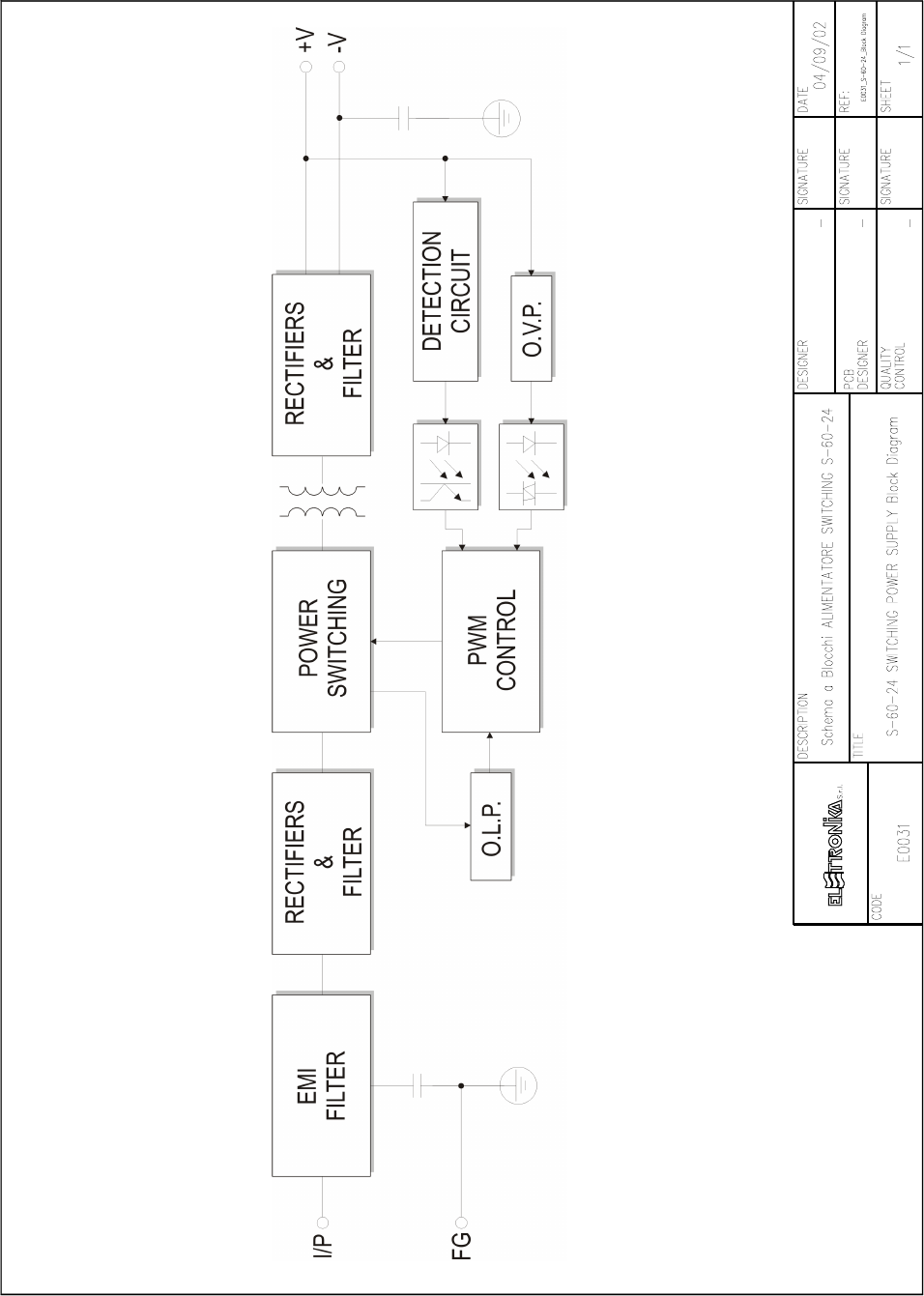
SPECIFICATION
MODEL S - 6 0 - 2 4
Input voltage 85 ~ 264VAC; 120 ~ 370VAC
Input frequency 47-63Hz
Inrush current Cold start, 30A/115V, 60A/230V
Output voltage Refer to below table (±10% ADJ.)
Overload protection 105% ~ 150% output pulsing code
Over voltage protection 115% ~ 135% of output voltage
Setup, rise, hold up time 800ms, 50ms, 10ms/115VAC
300ms, 50ms, 80ms/230VAC
Withstand voltage I/P-O/P:3kV, I/P-FG:1.5KV, 1min.
Working temp 0-50°C@100%, -10°C@80%, 60°C@60%
Safety standards UL 1012, UL 1950, TUV EN60950
EMC Standards EN55022 class B, EN61000-4-2,3,4,5, EN60555-2,3
Connection 5P/9.5mm pitch terminal block
Weight/Packing 0.55kgs/pcs; 30pcs/ 17kgs/ 1CUFT
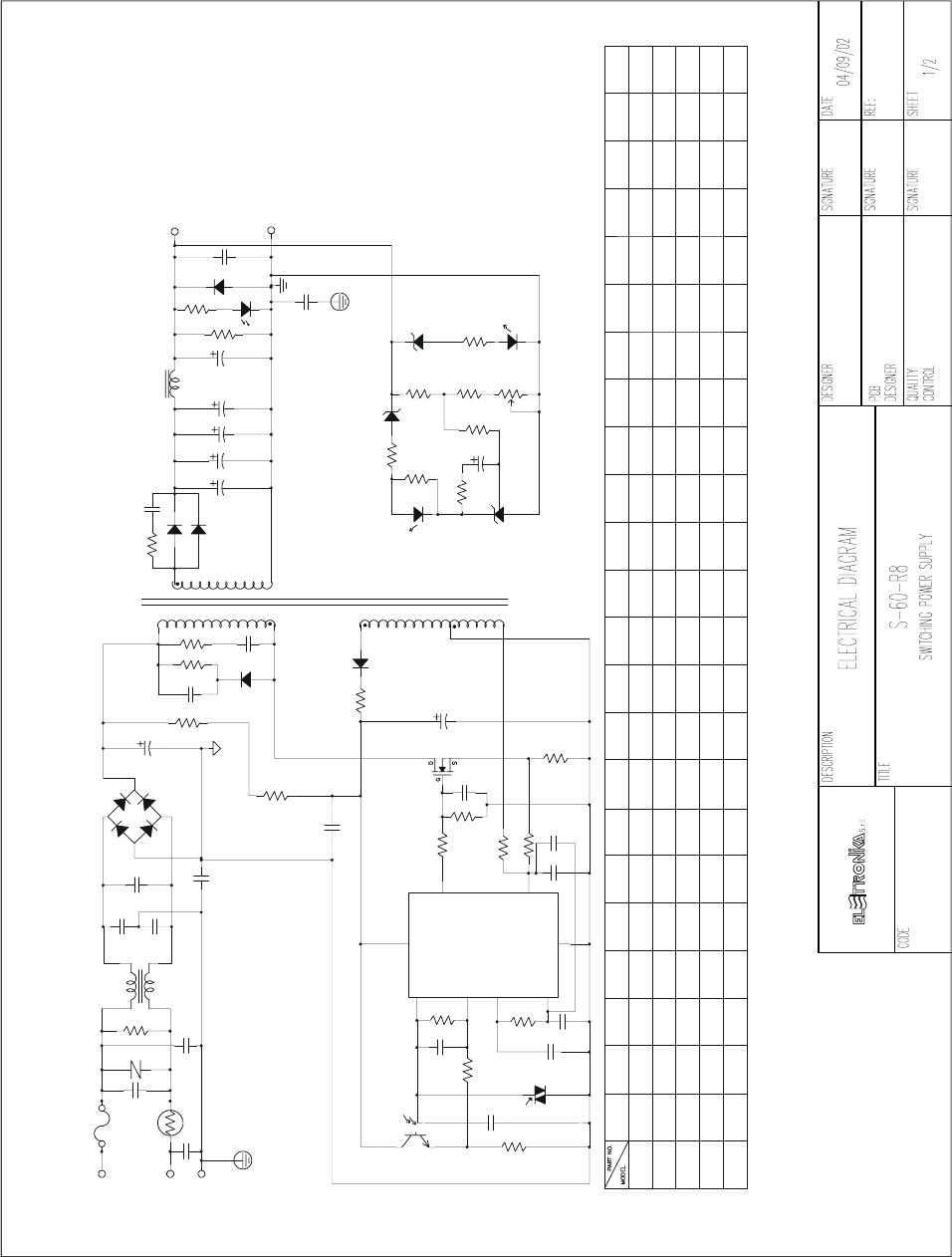
S-60-24 SWITCHING POWER SUPPLY E0031
Type No Output Tol. R&N Effi. P.P.
S-60-5 5V, 12A ± 2% 120mV 73% 58
S-60-12 12V, 5A ± 1% 120mV 76% 58
S-60-15 15V, 4A ± 1% 150mV 77% 58
S-60-24 24V, 2.5A ± 1% 150mV 79% 58
43
44
0.47U/50V
471/1KV
471/1KV
222/500V
15V
24V 104/100V
104/100V30V
12V 0.47U/50V 472/100V
1U/50V5V
S-60N DIFFERENT COMPONENT:
C18
103/50V
C20
103/50V
C13
R13
1K
C31
203/100V
3022
U3
R12
5K1
C14
223/50V
2
7
6
1
8
5
4
3
3842
U1
R10
680
R11
7K5
R7
5K1
R14
R9
C16
221/1KV
C15
471/50V
2200U/10V
C22C21
2200U/10V2200U/ 10V 2200U/10V
C23 C24 C25
2200U/10V
330U/35V X
330U/35V X
470U/25V
470u/25V
1000U/25V1000U/25V X 1000U /25V 470U/25V
X330U/35V
470U/25V
X470u/25V
330U/35V
330U/35V330U/35VX
U2
PC111
C12
474/250VAC
C1
C28
221/250VAC
C32
221/ 250VAC
FG
AC/N
FG
RTH1
10SP005
ZNR1
471
F 3A/250V
FS1
AC/L
BD1
4A/800V
R1
680K/1/2W
TF-096C1
LF1
472/250VAC
C3
C2
472/250VAC
C6
222/250VAC
104/250VAC
C4
R8
22
103/50V
C11
3
C9
47u/50V
Q1
2SK727
1
R5
5.1
D2
FR104
R29
47K/2W
5
T1
C5
150u/400V
R4
47K/2W
V-
R3
30K/3W
R2
330/3W
473/400V
C7
7
D1
EGP20J
101/1KV
C8
D4
D4
14-16
C20
R27
L2
C21
10-13
C22
C23
C24
R23
ZD3
JUMP
R17
U2
PC111
R22
2K2
BYQ28X-200 RB009
RB009
RB009BYQ28X-200
BYQ28X-200
BYQ28X-200 RB009 15K
15K 12K
7K5
15K 20K
1K5
24K22K
R17R14
10K
D4 L2
RB016CTB34M 2K
C10
472/50V
R6
2
1K5
R18
R19
R18
C18
R21
470
SHR1
TL431
SVR1
1K
10022
R20 R23 R26 R27
560 5.1/1/2W
2K 100 390
2K 390100
2K 22 220
22022 5.1/1/2W
5.1/1/2W2K7
4K7
2K7
47/1/2W
10K 47/1/ 2W 8200.39/2W1K/2W
820
820
0.39/2W
0.39/ 2W
680/2W
270/2W
0.39/2W270/2W 820 TF159-1 13.8V
TF161-1
TF160-1
TF158-1
17.9V
26.9V
33V/1WTF161-1
T1R6
0.33/2W39/2W
R28
680
R9
5.1V
ZD2
U3
3022 R20
C12R19
103/50V3K3
222/50V10K
222/50V
222/50V
20K
10K
222/50V20K
ZD2
C29
333/1KV
GND
+5V
D8
FR104
C30
104/100V
R26
GREEN
LED1
C25
R28

45
COMPONENT LIST S-60-24
SPECIFICATIONS QUANTITY POSITION
BOM FOR S-60-24 ON CASE 1
CASE 901-D-R1 M 1
CASE 901-T-R2 M 1
HS YS004W-055-R4 71268W-055 1 HS3
MHS002-R1 25mm 1 HS3
MYLAR FILM 901-R2 1
PR-7.5 1
BOX 901 168x105x45mm 1 1
SCREW F 3x6 ISO NI 2 HS3, HS3
SCREW F 3x18 ISO NI 1 HS3
SCREW T 3x6 ISO NI 2 HS1
SCREW P 3x6 ISO NI 1 CASE
LABEL UL S-60N-24-R2 1
LABEL IN/OUT UL BO17-R1 S-60N 1
CARTON 901 0.97CUFT 1 30
BOM FOR S-60-24 ON PCB 1
R/C 1/4W 5.1W 5% HP=10 T-52mm 1 R5
R/C 1/4W 22W 5% HP=10 T-52mm 1 R8
R/C 1/4W 100W 5% HP=10 T-52mm 1 R20
R/C 1/4W 390W 5% HP=10 T-52mm 1 R23
R/C 1/4W 470W 5% HP=10 T-52mm 1 R21
R/C 1/4W 680W 5% HP=10 T-52mm 1 R10
R/C 1/4W 820W 5% HP=10 T-52mm 1 R9
R/C 1/4W 1kW 5% HP=10 T-52mm 1 R13
R/C 1/4W 2kW 5% HP=10 T-52mm 1 R18
R/C 1/4W 2.2kW 5% HP=10 T-52mm 1 R22
R/C 1/4W 4.7kW 5% HP=10 T-52mm 1 R26
R/C 1/4W 5.1kW 5% HP=10 T-52mm 2 R12, R7
R/C 1/4W 7.5kW 5% HP=10 T-52mm 1 R11
R/C 1/4W 15kW 5% HP=10 T-52mm 1 R14
R/C 1/4W 20kW 5% HP=10 T-52mm 2 R17, R19
R/C 1/2W 47W 5% T-52mm 1 R27
R/C 1/2W 680kW 5% T-52mm 1 R1
R/MO 2W 680W 5% KINK 1 R28
R/MO 2W 47kW 5% 2 R29, R4
R/MO 3W 330W 5% MINI 1 R2
R/MO 3W 30kW 5% MINI 1 R3
R/NW 2W 0.39W 5% 1 R6
MVR 0.3W 1kW 10% HP=5x5 1 SCR1
NTC 4A 5W SCK054 KINK 1 RTH1
MOV 0.6W 470V TNR15G471K 1 ZNR1
JUMP 0.6 P=10 5 J1, J2, J3, J4, ZD3
JUMP 0.6 P=15 1 J5

46
SPECIFICATIONS QUANTITY POSITION
C/Y2 221/250VAC 20% P=7.5 AC 2 C28, C32
C/Y2 222/250VAC 20% P=7.5 AC 1 C6
C7Y2 472/250VAC 20% P=7.5 AC 2 C2, C3
C/X2 104/250VAC 20% P=15 KNB153X 1 C4
C/X2 474/250VAC 20% P=22 KNB153X 1 C1
C/M 473/400V 10% P=10 1 C7
C/M 104/63V 10% P=5 2 C18, C30
C/C 101/1KV 10% P=5 Y5P 1 C8
C/C 221/1KV 10% P=5 Y5P 1 C16
C/C 471/100V 10% P=5 Y5P 1 C15
C/C 471/1KV 10% P=5 Y5P 1 C20
C/ML 222/100V 5% P=3 1 C12
C/ML 472/100V 5% P=3 1 C10
C/ML 103/100V 5% P=3 2 C11, C13
C/ML 203/100V 5% P=5 1 C31
C/ML 223/100V 5% P=4.5 1 C14
C/C 333/1KV EPOXY 20% P=10 Z5V 1 C29
C/E 150u/400V 85°C 30x25 HP3 1 C5
C/E 47u/50V 105°C 6.3x11 KM 1 C9
C/E 330u/35V LL3K 10x16 YXG 3 C21, C24, C25
BD 4A/600V GLASS D3SB60 1 BD1
FRD 1A/400V FR104 T-52mm 2 D2, D8
SFRD BYQ28X-200 10A/200V TO220F 1 D4
SFRD EGP20J 2A/600V T-52mm 1 D1
ZD 1/2W 26.9V 2% 27-2 T-52mm 1 ZD2
LED GREEN 204GD-A 1 LED1
FET 2SK2652 6A/900V TO3P 1 Q1
SHR 431 2.5V 2% MM1431AT 1 SHR1
PHOTO CNX82A PC111 1 U2
PHOTO-TRIAC MOC3022 1 U3
PWM TL3842P TI 1 U1
RB-COIL RB009A 6x25 10. 1.5uH 1 L2
LF TF096C1 EE-25 0.5 23mH 1 LF1
MT TF161-1-R3 EER-35 1 T1
FUSE F3 L 250 5x20 G- U GFE/GMA 1 FS1
FUSE CLIP 5x20 2 FS1
TB HB 951-05P/DT49-B01W-05P 1 TB1
WIRE 07#18 100mm 05x05 1 F-F
HS HS001-R2 1 HS1
MHS002-R1 25mm 1 HS1
PCB S-60N-R5 CEM-1 20Z SS M1 1 PCB
SCREW F 3x12 ISO NI 1 Q1
SCREW P 3x6 ISO ZN 2 HS1
47
LDMOS - UHF TV AMPLIFIER
AUTV/1500LD
Users manual

48
This page is intentionally blank