Elster Solutions RX9A AUTOMATIC METER READING SYSTEM TRANSCEIVER User Manual IL42 4026
Elster Solutions, LLC AUTOMATIC METER READING SYSTEM TRANSCEIVER IL42 4026
UserManual.wiki
>
Elster Solutions
>
RX9A User Manual
>
Installation Instructions
Contents
1.
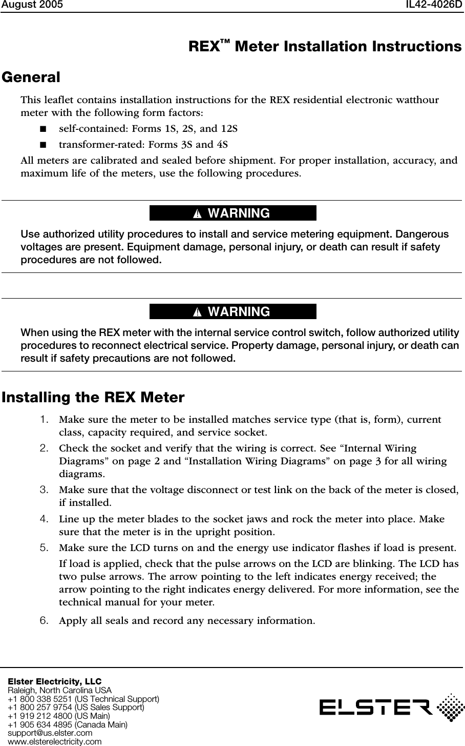
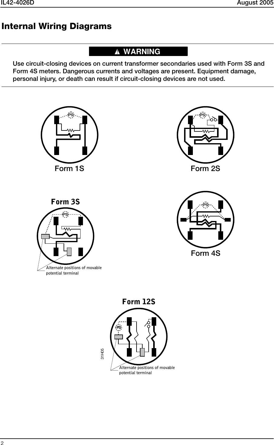
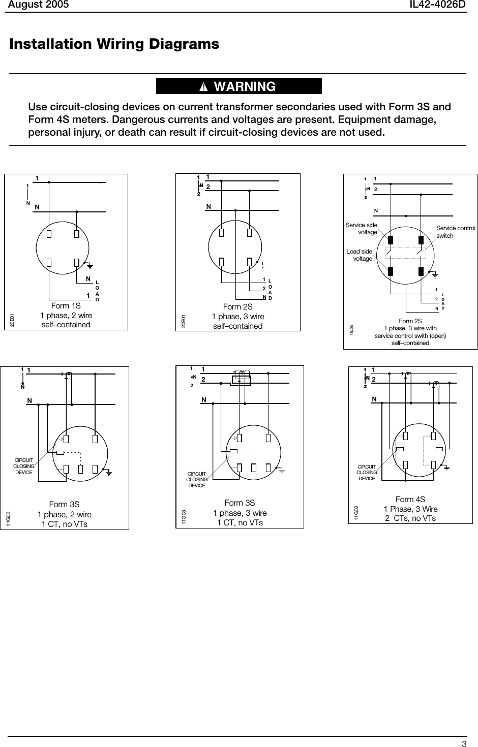
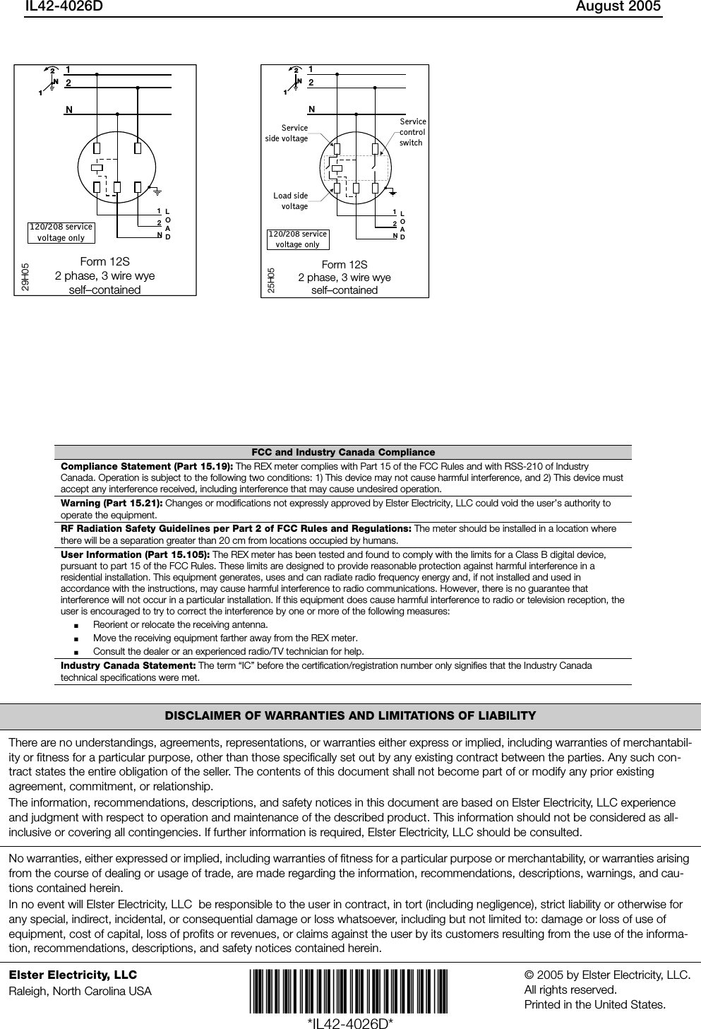
Installation Instructions
2.
User Manual
Installation Instructions
Navigation menu
Upload a User Manual
Namespaces
Wiki Guide
HTML
PDF
Info
Views
User Manual
Discussion / Help
Navigation