Enterprise Electronics RANGERX5 Ranger-X5 RADAR User Manual Section 2 Troubleshooting Maintenance Calibration v1 4 DRAFT 002

Enterprise Electronics Corporation Ranger-X5 RADAR Section 2 Troubleshooting Maintenance Calibration v1 4 DRAFT 002
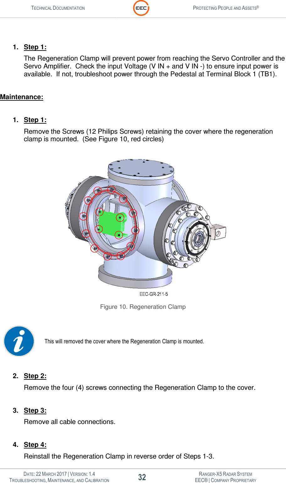
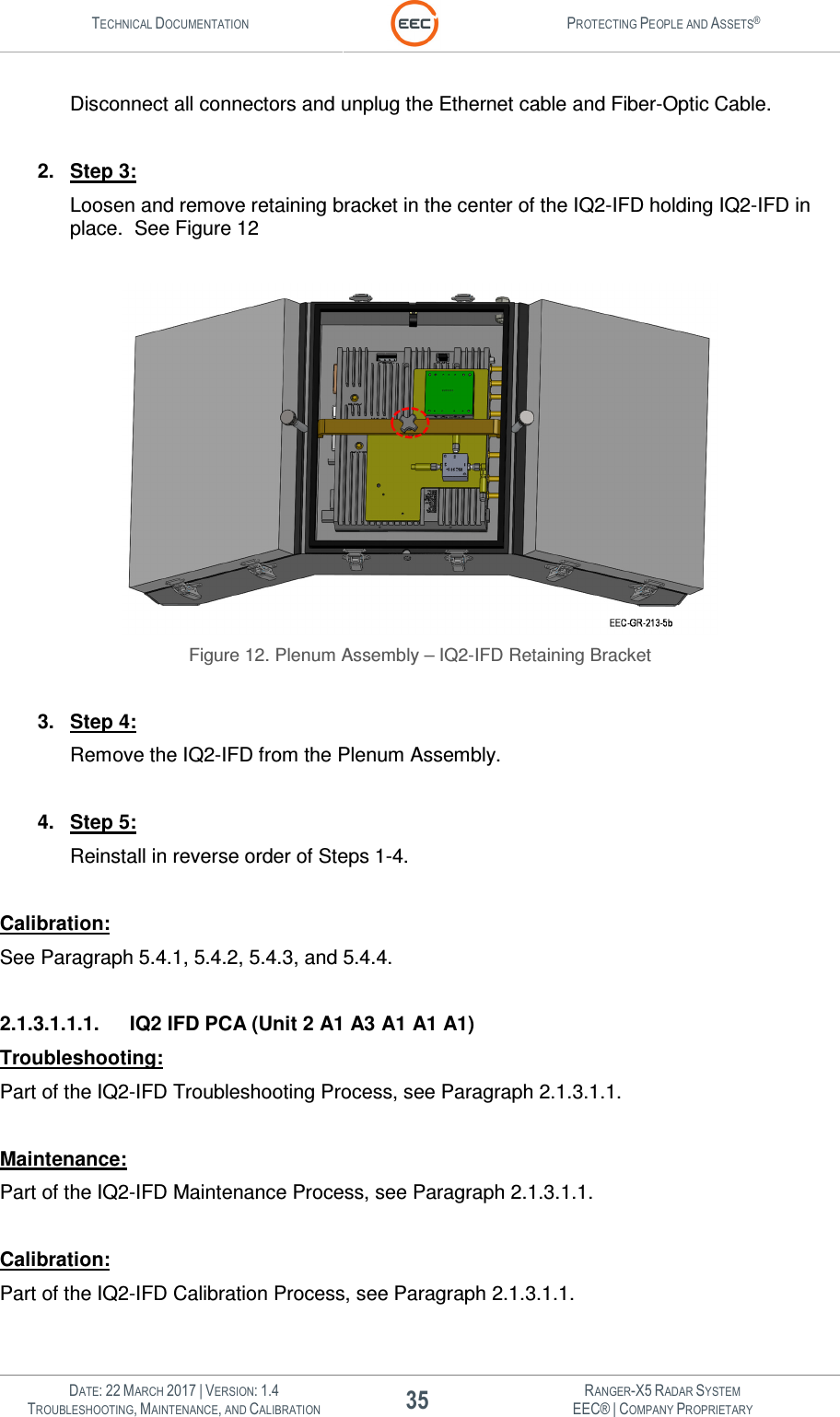
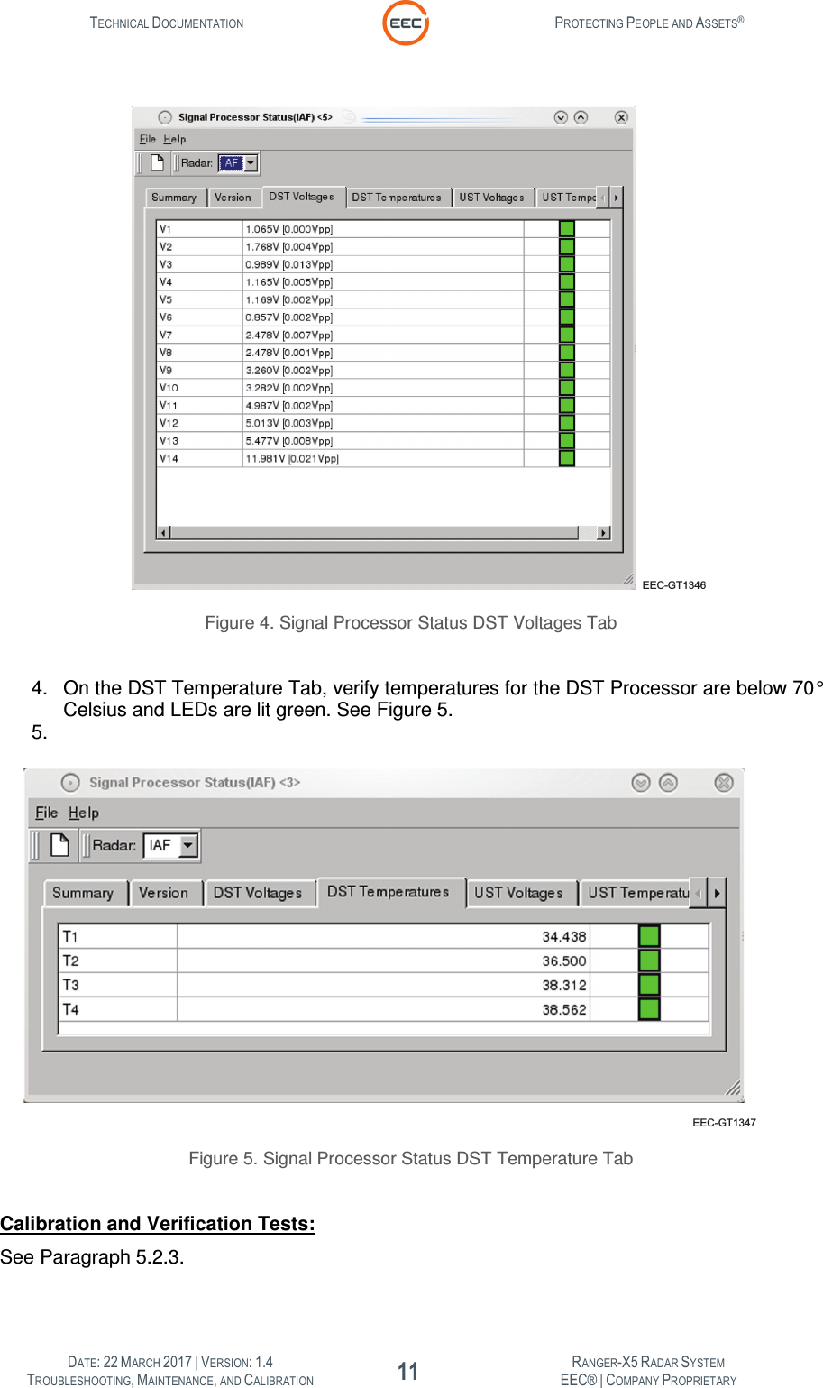
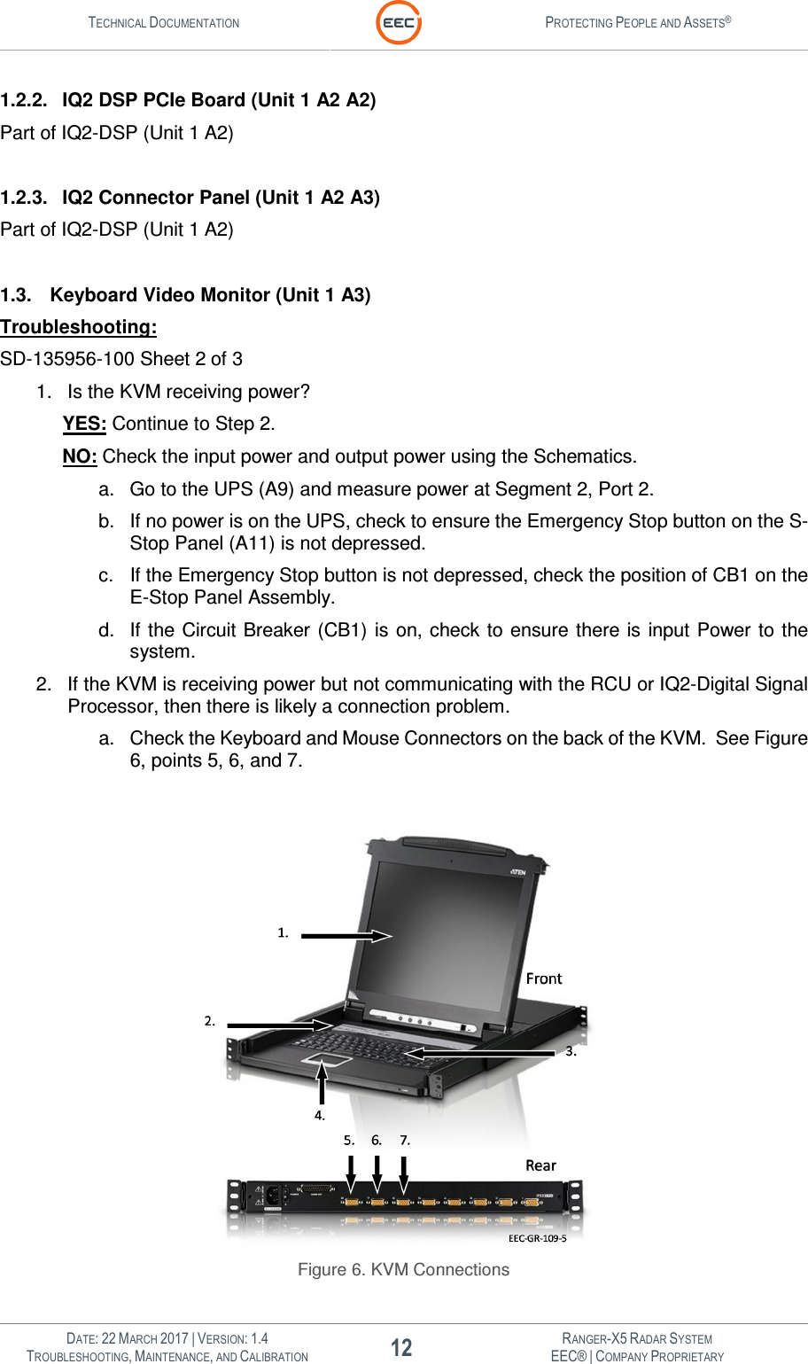
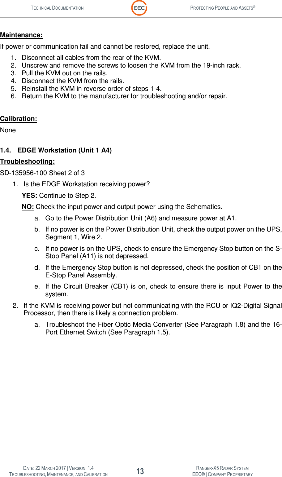
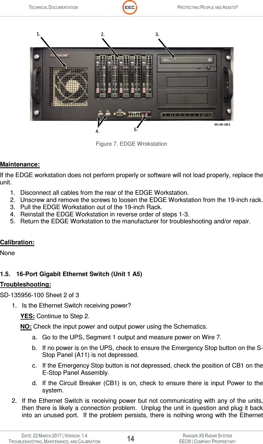
User Manual Troubleshooting Maintenance Calibration Part 1

 ® Enterprise Electronics Corporation TECHNICAL DOCUMENTATION SET OPERATIONS AND TECHNICAL MANUAL  RANGER® X5  TROUBLESHOOTING, MAINTENANCE, AND CALIBRATION  DESIGNED AND MANUFACTURED FOR: MOBILE CONFIGURATIONS  SECTION 2  JOB 9819    EEC • 128 SOUTH INDUSTRIAL BOULEVARD • ENTERPRISE, ALABAMA  36330 TELEPHONE (334) 347-3478 • FAX (334) 393-4556 • www.eecradar.com
   Official Enterprise Electronics Corporation (EEC) Indemnification Clause  The technical data and information (hereinafter “technical data”) contained herein is highly confidential and proprietary in nature and is the sole and exclusive intellectual property of the Enterprise Electronics Corporation ("EEC").  Any company, organization, entity or individual who seeks to benefit from the use of this technical data (“User”) agrees to hold said information in strict confidence.  User agrees that, unless required by law, it shall not disclose or make the technical data available in any form to a third party without the specific express written consent of EEC with regard to each such third party.  User agrees to take all necessary steps to ensure that Intellectual Property is not disclosed or distributed by its Directors, Officers, employees, representatives or agents in violation of this condition.  The User of the technical data contained herein agrees to defend (using counsel of EEC’s choosing), indemnify and hold harmless EEC, its Directors, Officers and its employees, parent company, affiliate companies and/or subsidiaries, its successors and assigns, customers and users of its Product(s) against all suits at law or in equity and from damages, claims and demands arising out of the death or injury to any person or damage of any kind to User's Directors, Officers, employees, agents or property as a result of User's use, misuse, assumptions or interpretations of the technical data contained herein.    EEC has made its best effort to offer the most current, correct, and clearly expressed information possible.  Nevertheless, inadvertent errors in information may occur.  In particular, but without limitation to the above, EEC disclaims any responsibility for typographical errors or punctuation errors contained herein.  EEC® is a registered Trademark of EEC. EEC PROTECTING PEOPLE AND ASSETS is a registered Trademark of EEC RANGER is a registered Trademark of EEC TELESPACE® is a registered Trademark of EEC EDGE is a Trademark of EEC.  Encoded Transmitted Signal In A Simultaneous Dual Polarization Weather System  United States Patent     US 7,439,899  Phase Shifted Transmitted Signals In A Simultaneous dual Polarization Weather System  United States Patent     US 7,551,123  Simultaneous Dual Polarization Radar System with Optical Communications Link  United States Patent     US 7,760,129  Simultaneous dual polarization radar systems offered by EEC are covered by one or more of the follow patents:  United States Patents     US 6,859,163 B2    (Inv-1)     US 6,803,875 B1    (Inv-2)     US 7,049,997    (Inv-3)   Foreign Patents     1200500266/13041 (OAPI African Organization)  (Inv-1)     200501316/009250 (EA Eurasia)     (Inv-1)     13694 (OAPI African Organization)    (Inv-3)     2394254 (Russia)        (Inv-3)  Simultaneous Dual Polarization Radar System Inv-2   Patented under European patent number 1608997   Various additional domestic and international patents have been applied for.  Validity Date:  24 September 2015
  FCC Part 15.19 Warning Statement- (Required for all Part 15 devices)   THIS DEVICE COMPLIES WITH PART 15 OF THE FCC RULES. OPERATION IS SUBJECT TO THE FOLLOWING TWO CONDITIONS: (1) THIS DEVICE MAY NOT CAUSE HARMFUL INTERFERENCE, AND (2) THIS DEVICE MUST ACCEPT ANY INTERFERENCE RECEIVED, INCLUDING INTERFERENCE THAT MAY CAUSE UNDESIRED OPERATION.  FCC Part 15.21 Warning Statement  NOTE:   THE GRANTEE IS NOT RESPONSIBLE FOR ANY CHANGES OR MODIFICATIONS NOT EXPRESSLY APPROVED BY THE PARTY RESPONSIBLE FOR COMPLIANCE. SUCH MODIFICATIONS COULD VOID THE USER’S AUTHORITY TO OPERATE THE EQUIPMENT.  FCC Part 15.105(b) Warning Statement- (ONLY Required for 15.109-JBP devices)  NOTE: This equipment has been tested and found to comply with the limits for a Class B digital device, pursuant to part 15 of the FCC Rules.  These limits are designed to provide reasonable protection against harmful interference in a residential installation.  This equipment generates uses and can radiate radio frequency energy and, if not installed and used in accordance with the instructions, may cause harmful interference to radio communications.  However, there is no guarantee that interference will not occur in a particular installation.  If this equipment does cause harmful interference to radio or television reception, which can be determined by turning the equipment off and on, the user is encouraged to try to correct the interference by one or more of the following measures:  • Reorient or relocate the receiving antenna. • Increase the separation between the equipment and receiver. • Connect the equipment into an outlet on a circuit different from that to which the receiver is connected. • Consult the manufacturer or an experienced radio/TV technician for help.  FCC Part 2.1091 Radiation Safety Warning NOTE: This equipment complies with the FCC RF radiation exposure limits set forth for an uncontrolled environment. This equipment should be installed and operated with a minimum distance of 22.43m between the radiator and any part of your body.
  RANGER X5 TUNING PROCEDURE  The power amplitude of the amplifier is completely dependent on the level of RF drive supplied to the amplifier. The RF drive is dependent on several factors. Drive amplitude is affected by the local oscillator output (which is adjustable in increments of 0.5 dBm), the 60 MHz IF output amplitude which derives from the output of the IFD, and the frequency to a lesser degree due to loss in the cabling.   The system will have a minimum output of 500 Watts (56.989 dBm), with an allowable overage of 0.792 dBm (Total Overage 600Watts (57.781dBm)). The maximum RF drive into the amplifier is +14 dBm, however the gain of two amps will not always yield the same output. Due to some minor inconsistencies in the gain and losses of the amplifiers, each amplifier may have its RF input drive increased or decreased. In other words, we have the ability to manipulate the RF drive to each amp independently from one another.  During factory testing the gain is set to around 10 dBm roughly to use as a starting point. The output of the amplifier is measured using a calibrated peak power meter (sensor) during this time. The RF drive is then adjusted through the use of SMA attenuators on the 60 MHz IF signal used in the up-convert chain for Input, Horizontal, and Vertical Channels. The local oscillator amplitude can be changed if necessary, however this will affect the drive to both amplifiers therefore, the local oscillator is set to a standard amplitude (typically 9 dBm), and drive adjustments are made by increasing or decreasing the 60 MHz amplitude as necessary to achieve the desired output power from the transmitters (Horizontal / Vertical).   SMA attenuators on the 60 MHz IF signal used in the up-convert chain for Input (3.), Horizontal (1.), and Vertical (2.) Channels.1. 2. 3.
  DATE: 22 MARCH 2017 | VERSION: 1.4 I RANGER-X5 RADAR SYSTEM TROUBLESHOOTING, MAINTENANCE, AND CALIBRATION EEC® | COMPANY PROPRIETARY  Revision Information  REVISION  DATE  MODIFICATION 1.0  15 November 2014  Initial Release 1.1  3 February 2015  Updated with latest procedures per ECNs 1.2  14 February 2017  Updated with latest procedures per ECNs 1.3  15 March 2017  Updated FCC radiation warning and tuning procedures 1.4  22 March 2017  Updated tuning procedures
  DATE: 22 MARCH 2017 | VERSION: 1.4 II RANGER-X5 RADAR SYSTEM TROUBLESHOOTING, MAINTENANCE, AND CALIBRATION EEC® | COMPANY PROPRIETARY  TABLE OF CONTENTS 1. Control Cabinet – Outdoor (Unit 1) ....................................................................................................... 9 1.1. RCU with Serial Card (Unit 1 A1) .......................................................................................................... 9 1.1.1. Computer System (Unit 1 A1 A1) .......................................................................................................... 9 1.1.2. Synclink GT 4E 4-Port Adapter (Unit 1 A1 A2) ................................................................................. 9 1.2. IQ2 Digital Signal Processor (Unit 1 A2)........................................................................................... 10 1.2.1. IQ2 Host Computer (Unit 1 A2 A1) ..................................................................................................... 10 1.2.2. IQ2 DSP PCIe Board (Unit 1 A2 A2) .................................................................................................. 12 1.2.3. IQ2 Connector Panel (Unit 1 A2 A3) .................................................................................................. 12 1.3. Keyboard Video Monitor (Unit 1 A3) .................................................................................................. 12 1.4. EDGE Workstation (Unit 1 A4)............................................................................................................. 13 1.5. 16-Port Gigabit Ethernet Switch (Unit 1 A5) .................................................................................... 14 1.6. Power Distribution Unit (Unit 1 A6) ..................................................................................................... 15 1.7. Fiber-Optic Coupler (Unit 1 A7) ........................................................................................................... 16 1.8. Fiber Optic Media Converter Assembly (Unit 1 A8) ...................................................................... 16 1.8.1. 7-Port Ethernet Switch with 1-Fiber Optic Port (Unit 1 A8 A1) .................................................. 16 1.8.2. 24VDC Power Supply (Unit 1 A8 PS1) ............................................................................................. 16 1.9. UPS, 2000/1800 KVA (Unit 1 A9) ....................................................................................................... 18 1.10. E-Stop Panel (Unit 1 A12) ..................................................................................................................... 18 1.11. DC Power Distribution Plate (Unit 1 A13)......................................................................................... 19 1.11.1. Lightning Protection Module (Unit 1 A13 A1) .................................................................................. 20 1.11.2. Contactor, 3-Phase, 24VDC (Unit 1 A13 K1) .................................................................................. 20 1.11.3. Safety Relay (Unit 1 A13 K2) ............................................................................................................... 21 1.11.4. 24VDC Power Supply (Unit 1 A13 PS1) ........................................................................................... 21 1.11.5. 48VDC Power Supply (Unit 1 A13, PS2) .......................................................................................... 22 1.11.6. 24VDC Power Supply, 600W, 27A Peak (Unit 1 A13 PS3) ........................................................ 22 1.11.7. 12VDC Power Supply (Unit 1 A13 PS4) ........................................................................................... 23 1.12. I/O Panel Assembly (Unit 1 A14) ........................................................................................................ 24 1.13. Control Cabinet Modification (Unit 1 MP1) ....................................................................................... 24 2. Antenna / Pedestal (Unit 2) ................................................................................................................... 27 2.1. Pedestal Assembly (Unit 2 A1) ............................................................................................................ 27 2.1.1. Azimuth Assembly (Unit 2 A1 A1) ....................................................................................................... 27 2.1.1.1. Slip Ring with Fiber Optic Rotary Joint (Unit 2 A1 A1 A1) .......................................................... 27 2.1.1.2. Actuator Unit (Unit 2 A1 A1 A2) ........................................................................................................... 27 2.1.2. Elevation Assembly (Unit 2 A1 A2) .................................................................................................... 27 2.1.2.1. Elevation Endcap Assembly (Unit 2 A1 A2 A1) .............................................................................. 27 2.1.2.1.1. Actuator Unit .............................................................................................................................................. 28 2.1.2.2. Elevation Driven Side Unit (Unit 2 A1 A2 A2) ................................................................................. 28 2.1.2.3. Servo Amplifier, 100V, 10A (Unit 2 A1 A2 A3) ............................................................................... 28 2.1.2.4. Aquarian Servo Controller PCA (Unit 2 A1 A2 A4) ....................................................................... 30 2.1.2.5. Regeneration Clamp (Unit 2 A1 A2 A5) ............................................................................................ 31 2.1.3. Payload Support Assembly (Unit 2 A1 A3) ...................................................................................... 33 2.1.3.1. Plenum Assembly (Unit 2 A1 A3 A1) ................................................................................................. 33 2.1.3.1.1. IQ2 Intermediate Frequency Digitizer Assembly (Unit 2 A1 A3 A1 A1) .................................. 33 2.1.3.1.2. I/O Control Module (Unit 2 A1 A3 A1 A3) ......................................................................................... 36 2.1.3.1.3. Cold Plate, Weatherized (Unit 2 A1 A3 A1 A4) .............................................................................. 40 2.1.3.1.4. 8-Port Ethernet Switch (Unit 2 A1 A3 A1 A5) .................................................................................. 42 2.1.3.1.5. Peltier Device Temperature Controller (Unit 2 A1 A3 A1 A6, A7) ............................................ 43 2.1.3.2. Transceiver Assembly (Horizontal) (Unit 2 A1 A3 A2) ................................................................. 44 2.1.3.2.1. 500W Power Amplifier (Unit 2 A1 A3 A2 A1) .................................................................................. 45 2.1.3.2.2. Horizontal UDC / Transmitter Control (Unit 2 A1 A3 A2 A2) ...................................................... 45 2.1.3.2.3. Transceiver Power Supply Unit (Unit 2 A1 A3 A2 A3) ................................................................. 49 2.1.3.2.4. Temperature / Humidity Sensor (Unit 2 A1 A3 A2 A4) ................................................................. 50 2.1.3.2.5. Crossguide Coupler (Unit 2 A1 A3 A2 DC1) ................................................................................... 51 2.1.3.2.6. 3-Port Circulator (Unit 2 A1 A3 A2 HY1)........................................................................................... 51 2.1.3.2.7. TR Limiter (Unit 2 A1 A3 A2 V1) ......................................................................................................... 52 2.1.3.3. Transceiver Assembly (Vertical) (Unit 2 A1 A3 A3) ...................................................................... 52 2.1.3.3.1. 500W Power Amplifier (Unit 2 A1 A3 A3 A1) .................................................................................. 52 2.1.3.3.2. Vertical UDC / Transmitter Control (Unit 2 A1 A3 A3 A2) ........................................................... 53 2.1.3.3.3. Transceiver Power Supply Unit (Unit 2 A1 A3 A3 A3) ................................................................. 53
  DATE: 22 MARCH 2017 | VERSION: 1.4 III RANGER-X5 RADAR SYSTEM TROUBLESHOOTING, MAINTENANCE, AND CALIBRATION EEC® | COMPANY PROPRIETARY  2.1.3.3.4. Temperature / Humidity Sensor (Unit 2 A1 A3 A3 A4) ................................................................. 53 2.1.3.3.5. Crossguide Coupler (Unit 2 A1 A3 A3 DC1) ................................................................................... 53 2.1.3.3.6. 3-Port Circulator (Unit 2 A1 A3 A3 HY1)........................................................................................... 53 2.1.3.3.7. TR Limiter (Unit 2 A1 A3 A3 V1) ......................................................................................................... 54 2.1.3.4. Fluid Pump Assembly (Unit 2 A1 A3 A4) .......................................................................................... 54 2.1.3.5. Weatherized Liquid Cooler (Unit 2 A1 A4 A6)................................................................................. 54 2.1.4. V-Clamp Pedestal Assembly (Unit 2 A1 A4) ................................................................................... 54 2.1.5. Pedestal Enclosure Plate Assembly (Unit 2 A1 A5)...................................................................... 55 2.1.5.1. 7-Port Ethernet Switch with 1-Fiber Optic Port (Unit 2 A1 A5 A1) ........................................... 55 2.1.5.2. Servo Amplifier, 100V, 10A (Unit 2 A1 A5 A2) ............................................................................... 55 2.1.5.3. Fiber Optic Coupler (Unit 2 A1 A5 A3) .............................................................................................. 57 2.1.5.4. Aquarian Servo Controller PCA (Unit 2 A1 A5 A4) ....................................................................... 57 2.1.5.5. Regeneration Clamp (Unit 2 A1 A5 A5) ............................................................................................ 59 3. Radome (Unit 3) ....................................................................................................................................... 63 4. System Troubleshooting ........................................................................................................................ 67 4.1. Control Cabinet ......................................................................................................................................... 67 4.1.1. Power ........................................................................................................................................................... 67 4.2. Pedestal System ....................................................................................................................................... 67 4.2.1. Azimuth Rotation ...................................................................................................................................... 67 4.2.2. Elevation Rotation .................................................................................................................................... 67 4.3. Communication ......................................................................................................................................... 68 4.3.1. Network Communication ........................................................................................................................ 68 4.3.2. Control Cabinet to/from Pedestal ........................................................................................................ 68 5. System Level Calibrations ..................................................................................................................... 71 5.1.1. Peak Power / Pulse Width and PRF Range Measurement ........................................................ 71 5.1.2. Transmission / Reception Mode (Horizontal and Vertical) Verification Procedure ............. 74 5.1.3. Operating Range and Range Resolution Verification Procedure ............................................. 74 5.1.4. Unambiguous Velocity and Dual PRF Mode Verification Procedure....................................... 75 5.1.5. Data Output Verification Procedure.................................................................................................... 75 5.2. Transmitter Verification Procedures ................................................................................................... 76 5.2.1. Transmitter Control and Indicator Test .............................................................................................. 76 5.2.2. Transmitter Control Panel Switches and Indicators Test ............................................................ 76 5.2.3. IQ2 Signal Processor Status Tests .................................................................................................... 77 5.3. Antenna / Pedestal Tests....................................................................................................................... 80 5.3.1. Elevation Level Verification Test ......................................................................................................... 80 5.3.2. Electrical Limit Switch Test ................................................................................................................... 80 5.3.3. Antenna Speed and Pointing Accuracy Test ................................................................................... 81 5.3.4. System Interlock and Safe Switch Test ............................................................................................ 81 5.3.4.1. Azimuth Safe Switch Verification Test ............................................................................................... 81 5.3.4.2. Elevation Safe Switch Verification Test ............................................................................................ 82 5.3.5. Azimuth Orientation and Sun-Track Verification ............................................................................ 82 5.4. Receiver Performance Verification Test ........................................................................................... 83 5.4.1. IQ2 Receiver Noise Level Verification ............................................................................................... 83 5.4.2. IQ2 Receiver Calibration and Dynamic Range Verification ........................................................ 83 5.4.3. Minimum Discernable Signal (MDS) Measurement and Verification Test ............................. 85 5.4.4. Clutter Filter and Clutter Rejection Verification Test ..................................................................... 85
  DATE: 22 MARCH 2017 | VERSION: 1.4 IV RANGER-X5 RADAR SYSTEM TROUBLESHOOTING, MAINTENANCE, AND CALIBRATION EEC® | COMPANY PROPRIETARY  TABLE OF FIGURES  Figure 1. Outdoor Control Cabinet ....................................................................................................................................... 3 Figure 2. 1.8 Meter Ranger-X5 Variant .............................................................................................................................. 4 Figure 3. Signal Processor Status Summary Tab ......................................................................................................... 10 Figure 4. Signal Processor Status DST Voltages Tab ................................................................................................. 11 Figure 5. Signal Processor Status DST Temperature Tab ......................................................................................... 11 Figure 6. KVM Connections ................................................................................................................................................. 12 Figure 7. EDGE Wrokstation ................................................................................................................................................ 14 Figure 8. 24VDC Power Supply .......................................................................................................................................... 18 Figure 9. Servo Amplifier Removal .................................................................................................................................... 29 Figure 10. Regeneration Clamp .......................................................................................................................................... 32 Figure 11. Plenum Assembly – Cover Retaining Screws and Latches .................................................................. 34 Figure 12. Plenum Assembly – IQ2-IFD Retaining Bracket ....................................................................................... 35 Figure 13. Ethernet Switch Retaining Brackets ............................................................................................................. 43 Figure 14. Temperature Controller Retaining Screws ................................................................................................. 44 Figure 15. UDC / Transmitter Control Signal Flow........................................................................................................ 48 Figure 16. Servo Amplifier Removal .................................................................................................................................. 56 Figure 17. Regeneration Clamp .......................................................................................................................................... 59 Figure 18. Test Setup for Peak Power Measurements ............................................................................................... 72 Figure 19 UST Temperature Tab ....................................................................................................................................... 77 Figure 20 UST Voltages Tab................................................................................................................................................ 78 Figure 21 DST Temperatures Tab ..................................................................................................................................... 79 Figure 22 DST Voltages Tab................................................................................................................................................ 80 Figure 23. Typical Calibration Test Results Screenshot (LDR > 100dB) .............................................................. 85    TABLE OF TABLES  Table 1. Discrete (Digital) I/O Module ............................................................................................................................... 37 Table 2. Analog I/O Map ........................................................................................................................................................ 39 Table 3. Transceiver and UDC Voltages .......................................................................................................................... 45 Table 4. UDC / TX Control Power Distribution ............................................................................................................... 47 Table 5 Power Sensor Worksheet...................................................................................................................................... 71 Table 6 Typical power Sensor Specifications ................................................................................................................. 71 Table 7 Peak Power Calculation using Duty Cycle Correction ................................................................................. 73 Table 8 Example of Peak Power Calculation.................................................................................................................. 73 Table 9. Peak Power Test Results ..................................................................................................................................... 74 Table 10. Velocity Scale and Nyquist Interval ................................................................................................................ 75 Table 11. Data Output Verification ..................................................................................................................................... 75 Table 12 Transmitter Control Panel Switches and Indicators Reference Table .................................................. 76 Table 13. Receiver Noise Figure and Dynamic Range Test Results ...................................................................... 84
  DATE: 22 MARCH 2017 | VERSION: 1.4 V RANGER-X5 RADAR SYSTEM TROUBLESHOOTING, MAINTENANCE, AND CALIBRATION EEC® | COMPANY PROPRIETARY  This page intentionally blank.
TECHNICAL DOCUMENTATION  PROTECTING PEOPLE AND ASSETS®   DATE: 22 MARCH 2017 | VERSION: 1.4 1 RANGER-X5 RADAR SYSTEM TROUBLESHOOTING, MAINTENANCE, AND CALIBRATION EEC® | COMPANY PROPRIETARY  INTRODUCTION  SYSTEM INTRODUCTION AND OVERVIEW
TECHNICAL DOCUMENTATION  PROTECTING PEOPLE AND ASSETS®   DATE: 22 MARCH 2017 | VERSION: 1.4 2 RANGER-X5 RADAR SYSTEM TROUBLESHOOTING, MAINTENANCE, AND CALIBRATION EEC® | COMPANY PROPRIETARY  This page intentionally blank.
TECHNICAL DOCUMENTATION  PROTECTING PEOPLE AND ASSETS®   DATE: 22 MARCH 2017 | VERSION: 1.4 3 RANGER-X5 RADAR SYSTEM TROUBLESHOOTING, MAINTENANCE, AND CALIBRATION EEC® | COMPANY PROPRIETARY  The Enterprise Electronics Corporation (EEC) Ranger-X5 radar system is a new generation, X-band (3 cm), Adaptive Polarization Doppler Weather Surveillance Radar that fills the gap between high-cost, high-power traditional radar systems and the passive ground-station weather sensors.  The system uses relatively low power solid-state transmitters and pulse compression technology to  attain  nearly  the  same  performance  capabilities  of  much  more  expensive  traditional  radar systems.    The  Ranger-X5  employs  Adaptive  Dual  Polarization  (ADP)  techniques  to  allow Alternating or Simultaneous Dual Polarization capability with total control over the transmission polarization state using dual independent coherent transmitters.  The entire Ranger-X5 design concept emphasizes precision, stability, reliability, and value using proven  solid-state  technology  combined  with  the  most  advanced  motion  control  system  ever conceived  for  weather  radar.    The  sealed,  lubricated  for  life,  mechanical  drive  system  in  the Ranger-X5 has an MTBF in excess of 180,000 hours without the need for routine maintenance or lubrication.  The motion system provides extremely high torque to weight ratios for outdoor operation and greater than 40 arc-second position accuracy.  Advanced configurations and networks of systems are available that meet all of the requirements for special missions, such as aviation or hydrological forecasting applications.  The  flexible  architecture  and  system  design  facilitates  automatic  remote  operations,  ensures minimal maintenance costs, and provides maximum configurability to meet specialized customer needs.    The  Ranger-X5  is  designed  for  continuous  (24  hours/day),  unattended  operations  at remote locations, providing the full suite of polarimetric radar data for local single-site operations, as a member of a network with predefined product contributions or, as the manager of a network of remote users providing specific radar products to suite the individual user’s needs.    Figure 1. Outdoor Control Cabinet  The  Ranger-X5  radar  system  is  a  lightweight,  high  performance  system  designed  for  tactical grade deployments on a wide variety of fixed and mobile platforms.  This densely packed system provides stability, stiffness, position accuracy and raw power directly coupled to the payload.
TECHNICAL DOCUMENTATION  PROTECTING PEOPLE AND ASSETS®   DATE: 22 MARCH 2017 | VERSION: 1.4 4 RANGER-X5 RADAR SYSTEM TROUBLESHOOTING, MAINTENANCE, AND CALIBRATION EEC® | COMPANY PROPRIETARY  The 1-meter variant shown in FIGURE XX is capable of supporting full operation in sustained winds up to 75 mph, and with wind gusts to 90 mph.  To deliver radar and motor cooling, the system provides for water-cooling using naval shipboard cooling techniques.      Figure 2. 1.8 Meter Ranger-X5 Variant  The  standard  Ranger-X5  system  configuration  includes  an  elevation  over  azimuth  pedestal providing  on-board,  environmentally  sealed,  and  controlled  electronics  housing  for  the transmitters, receivers, and signal digitizer in conjunction with a NEMA 4 grade environmentally controlled ground interface enclosure.  The ground interface contains the system power supplies, EEC  IQ2  signal  processor,  Local  Control  Interface  (LCI)  station,  Radar  Control  Unit  (RCU) Computer  running  EEC  COBRA  software,  EEC  EDGE  software  system  workstation,  and associated  communication  interfaces.    The  ground  interface  enclosure  is  not  required  with customer furnished facilities. The standard configuration uses two 500-Watt transmitters located on the pedestal above the elevation rotational axis to support Dual Polarization operation.  This design eliminates the need for  waveguide  switches,  waveguide  rotary  joints,  or  a  power  splitter,  allowing  for  complete diversity  in  H/V measurement  schemes  and minimum  path  loss  in both  the  transmission  and reception path. The radar system  provides  standard  precipitation  intensity, turbulence, and velocity modes of analysis with extremely high precision in all modes of operation.  Normal radar control and data processing utilizes the EDGE Radar Control and Analysis Software.  A separate technical manual
TECHNICAL DOCUMENTATION  PROTECTING PEOPLE AND ASSETS®   DATE: 22 MARCH 2017 | VERSION: 1.4 5 RANGER-X5 RADAR SYSTEM TROUBLESHOOTING, MAINTENANCE, AND CALIBRATION EEC® | COMPANY PROPRIETARY  describes the functions of EDGE. The transmitter provides a 500W peak RF power pulse (in each channel) with an adjustable pulse width from 0.2 and 100.0 microseconds (µs), providing excellent weather detection at range in all modes.  The transmitter radiates in staggered Pulse Repetition Frequency (PRF) modes at 3:2, 4:3, or 5:4 ratio allowing dual PRF sampling by the digital signal processor to produce maximum unambiguous velocities of up to ≥90 meters/second. The EEC IQ2-IFD Intermediate Frequency Digitizer ingests and digitizes the received radar return in 16-bit  resolution.   The  receiver  design utilizes state-of-the-science  components  to  optimize detection sensitivity, bandwidth, dynamic range, measurement accuracy, and useful life.  The IQ2-IFD converts the analog receiver IF signals into the digital domain.  The IQ2-DSP Digital Signal Processor receives the digitized Inphase /  Quadranture (I/Q)  data  via the PCI receiver card.    The  I/Q  data  stream  is  pre-processed  and  polar  rays  of  meteorological  moments  are generated.  The ray data is sent via a 1Gbit TCP/IP connection to the IQ2-DSP Signal Processor for storage and further processing.  The IQ2 design optimizes detection sensitivity, bandwidth, dynamic range, measurement accuracy, and useful life.  The IQ2-DSP is the central data processing point for the radar.  The IQ2-DSP is an advanced scientific  computer  system  utilizing  the  Linux  operating  system  and  employs  advanced scientifically  validated  algorithms.    The  standard  mode  of  operation  is  the  proven  pulse-pair method of Doppler processing to produce the standard data moments of Uncorrected Reflectivity (U), Corrected Reflectivity (ZH), Vertical Reflectivity (ZV), Velocity (V), and Spectrum Width (W).  In  addition  to  the  standard  base  Moments  the  Ranger-X5  provides  the  Polarimetric  Base Moments  Differential  Reflectivity  (ZDR),  Differential  Phase  (ΦDP),  Specific  Differential  Phase (KDP), Correlation Coefficient (ρHV), and Linear Depolarization Ratio (LDR), (where applicable).  The derived moment of rainfall (R) is also included.  General system control utilizes the standard EEC Radar Control Unit (RCU).  The RCU is used to correlate and process BITE information from the various modules and procedures, control the antenna pedestal operational parameters and perform basic radar control.  The RCU integrates closely  with  the  IQ2  Digital  Receiver  and  IQ2  Digital  Signal  Processor,  communicating  by standard Ethernet Protocol.  The  radar  system  design  allows  for  easy  maintenance  and  has  a  manually  selectable local/remote mode to permit maintenance personnel to  gain local control of the radar system.  Local control is implemented on a Local Control Interface (LCI) Display using a system of menus and status screens.  With the automatic calibration functions and easily accessible system test points, any necessary system testing, calibration, or repair is easily accomplished with minimum down time.
TECHNICAL DOCUMENTATION  PROTECTING PEOPLE AND ASSETS®   DATE: 22 MARCH 2017 | VERSION: 1.4 6 RANGER-X5 RADAR SYSTEM TROUBLESHOOTING, MAINTENANCE, AND CALIBRATION EEC® | COMPANY PROPRIETARY  This page intentionally blank.
TECHNICAL DOCUMENTATION  PROTECTING PEOPLE AND ASSETS®   DATE: 22 MARCH 2017 | VERSION: 1.4 7 RANGER-X5 RADAR SYSTEM TROUBLESHOOTING, MAINTENANCE, AND CALIBRATION EEC® | COMPANY PROPRIETARY  CHAPTER 1  CONTROL CABINET (UNIT 1)
TECHNICAL DOCUMENTATION  PROTECTING PEOPLE AND ASSETS®   DATE: 22 MARCH 2017 | VERSION: 1.4 8 RANGER-X5 RADAR SYSTEM TROUBLESHOOTING, MAINTENANCE, AND CALIBRATION EEC® | COMPANY PROPRIETARY  This page intentionally blank.
TECHNICAL DOCUMENTATION  PROTECTING PEOPLE AND ASSETS®   DATE: 22 MARCH 2017 | VERSION: 1.4 9 RANGER-X5 RADAR SYSTEM TROUBLESHOOTING, MAINTENANCE, AND CALIBRATION EEC® | COMPANY PROPRIETARY  1.   Control Cabinet – Outdoor (Unit 1) 1.1.  RCU with Serial Card (Unit 1 A1) 1.1.1.  Computer System (Unit 1 A1 A1) Troubleshooting: SD-135956-100 Sheet 2 of 3 1.  Is the RCU receiving power? YES: Continue to Step 2.  NO: Check the input power and output power using the Schematics.   2.  Is the COBRA Software loading properly?   YES: Continue to Step 3. NO: Refer to Volume 5, Chapter 2, COBRA Operations. 3.  Are the communications with the network working properly?   YES: There is likely a problem with the COBRA Software load, Refer to Volume 2, Section 5, COBRA SW/FW Maintenance. NO:  Refer  to  paragraphs  1.5,  1.8.1,  and  2.1.5.1  to  ensure  the  Ethernet  Switches  are operating properly.  Maintenance: If the RCU system is inoperative OR the COBRA software will not load, replace the RCU.    1.  Disconnect all cables from the rear of the RCU. 2.  Use the quick disconnect latches to loosen the RCU from the 19-inch rack. 3.  Pull the RCU out on the rails. 4.  Disconnect the RCU from the rails. 5.  Reinstall the RCU in reverse order of steps 1-4. 6.  Return the RCU to the manufacturer for troubleshooting and/or repair.  Calibration: None Required  1.1.2.  Synclink GT 4E 4-Port Adapter (Unit 1 A1 A2) Part of Computer System (Unit 1 A1)
TECHNICAL DOCUMENTATION  PROTECTING PEOPLE AND ASSETS®   DATE: 22 MARCH 2017 | VERSION: 1.4 10 RANGER-X5 RADAR SYSTEM TROUBLESHOOTING, MAINTENANCE, AND CALIBRATION EEC® | COMPANY PROPRIETARY  1.2.  IQ2 Digital Signal Processor (Unit 1 A2) 1.2.1.  IQ2 Host Computer (Unit 1 A2 A1) Troubleshooting: SD-135956-100 Sheet 2 of 3  Maintenance: If the IQ2 Digital Signal Processor is inoperative OR the EDGE software will not load, replace the entire unit.    1.  Disconnect all cables from the rear of the IQ2-DSP. 2.  Loosen the screws retaining the IQ2-DSP in the 19-inch rack. 3.  Pull the IQ2-DSP out of the 19-inch rack. 4.  Reinstall the IQ2-DSP in reverse order of steps 1-3. 5.  Return the IQ2-DSP to the manufacturer for troubleshooting and/or repair.   Verification: This check is to verify the IQ2- Digital Signal Processor (DSP) (displayed as DST on EDGE) and the IQ2- Intermediate Frequency Digitizer (IFD) (displayed as UST on EDGE) are working within specified voltage and temperature limits. 1.  From EDGE Control screen, open the Signal Processor Status screen. 2.  On the Summary tab, verify the IQ2 and UST Uptime status. See Figure 3.  Figure 3. Signal Processor Status Summary Tab  3.  On  the  DST  Voltages  tab,  verify  all  voltages  are  within  specified  limits  and  the corresponding indicator is green. See Figure 4. EEC-GT1345
TECHNICAL DOCUMENTATION  PROTECTING PEOPLE AND ASSETS®   DATE: 22 MARCH 2017 | VERSION: 1.4 11 RANGER-X5 RADAR SYSTEM TROUBLESHOOTING, MAINTENANCE, AND CALIBRATION EEC® | COMPANY PROPRIETARY   Figure 4. Signal Processor Status DST Voltages Tab  4.  On the DST Temperature Tab, verify temperatures for the DST Processor are below 70° Celsius and LEDs are lit green. See Figure 5. 5.    Figure 5. Signal Processor Status DST Temperature Tab  Calibration and Verification Tests: See Paragraph 5.2.3. EEC-GT1346EEC-GT1347
TECHNICAL DOCUMENTATION  PROTECTING PEOPLE AND ASSETS®   DATE: 22 MARCH 2017 | VERSION: 1.4 12 RANGER-X5 RADAR SYSTEM TROUBLESHOOTING, MAINTENANCE, AND CALIBRATION EEC® | COMPANY PROPRIETARY  1.2.2.  IQ2 DSP PCIe Board (Unit 1 A2 A2) Part of IQ2-DSP (Unit 1 A2)  1.2.3.  IQ2 Connector Panel (Unit 1 A2 A3) Part of IQ2-DSP (Unit 1 A2)  1.3.  Keyboard Video Monitor (Unit 1 A3) Troubleshooting: SD-135956-100 Sheet 2 of 3 1.  Is the KVM receiving power?   YES: Continue to Step 2.  NO: Check the input power and output power using the Schematics.   a.  Go to the UPS (A9) and measure power at Segment 2, Port 2.   b.  If no power is on the UPS, check to ensure the Emergency Stop button on the S-Stop Panel (A11) is not depressed. c.  If the Emergency Stop button is not depressed, check the position of CB1 on the E-Stop Panel Assembly. d.  If the Circuit Breaker  (CB1) is on, check to ensure there  is  input  Power to the system. 2.  If the KVM is receiving power but not communicating with the RCU or IQ2-Digital Signal Processor, then there is likely a connection problem. a.  Check the Keyboard and Mouse Connectors on the back of the KVM.  See Figure 6, points 5, 6, and 7.   Figure 6. KVM Connections
TECHNICAL DOCUMENTATION  PROTECTING PEOPLE AND ASSETS®   DATE: 22 MARCH 2017 | VERSION: 1.4 13 RANGER-X5 RADAR SYSTEM TROUBLESHOOTING, MAINTENANCE, AND CALIBRATION EEC® | COMPANY PROPRIETARY  Maintenance: If power or communication fail and cannot be restored, replace the unit. 1.  Disconnect all cables from the rear of the KVM. 2.  Unscrew and remove the screws to loosen the KVM from the 19-inch rack. 3.  Pull the KVM out on the rails. 4.  Disconnect the KVM from the rails. 5.  Reinstall the KVM in reverse order of steps 1-4. 6.  Return the KVM to the manufacturer for troubleshooting and/or repair.  Calibration: None  1.4.  EDGE Workstation (Unit 1 A4) Troubleshooting: SD-135956-100 Sheet 2 of 3 1.  Is the EDGE Workstation receiving power?   YES: Continue to Step 2.  NO: Check the input power and output power using the Schematics.   a.  Go to the Power Distribution Unit (A6) and measure power at A1.   b.  If no power is on the Power Distribution Unit, check the output power on the UPS, Segment 1, Wire 2. c.  If no power is on the UPS, check to ensure the Emergency Stop button on the S-Stop Panel (A11) is not depressed. d.  If the Emergency Stop button is not depressed, check the position of CB1 on the E-Stop Panel Assembly. e.  If the Circuit Breaker  (CB1) is on, check to ensure there  is  input  Power to the system. 2.  If the KVM is receiving power but not communicating with the RCU or IQ2-Digital Signal Processor, then there is likely a connection problem. a.  Troubleshoot the Fiber Optic Media Converter (See Paragraph 1.8) and the 16-Port Ethernet Switch (See Paragraph 1.5).
TECHNICAL DOCUMENTATION  PROTECTING PEOPLE AND ASSETS®   DATE: 22 MARCH 2017 | VERSION: 1.4 14 RANGER-X5 RADAR SYSTEM TROUBLESHOOTING, MAINTENANCE, AND CALIBRATION EEC® | COMPANY PROPRIETARY   Figure 7. EDGE Wrokstation  Maintenance: If the EDGE workstation does not perform properly or software will not load properly, replace the unit. 1.  Disconnect all cables from the rear of the EDGE Workstation. 2.  Unscrew and remove the screws to loosen the EDGE Workstation from the 19-inch rack. 3.  Pull the EDGE Workstation out of the 19-inch Rack. 4.  Reinstall the EDGE Workstation in reverse order of steps 1-3. 5.  Return the EDGE Workstation to the manufacturer for troubleshooting and/or repair.  Calibration: None  1.5.  16-Port Gigabit Ethernet Switch (Unit 1 A5) Troubleshooting: SD-135956-100 Sheet 2 of 3 1.  Is the Ethernet Switch receiving power?   YES: Continue to Step 2.  NO: Check the input power and output power using the Schematics.   a.  Go to the UPS, Segment 1 output and measure power on Wire 7.   b.  If no power is on the UPS, check to ensure the Emergency Stop button on the S-Stop Panel (A11) is not depressed. c.  If the Emergency Stop button is not depressed, check the position of CB1 on the E-Stop Panel Assembly. d.  If the Circuit Breaker  (CB1) is on, check to ensure there  is  input  Power to the system. 2.  If the Ethernet Switch is receiving power but not communicating with any of the units, then there is likely a connection problem.  Unplug the unit in question and plug it back into an unused port.  If the problem persists, there is nothing wrong with the Ethernet
TECHNICAL DOCUMENTATION  PROTECTING PEOPLE AND ASSETS®   DATE: 22 MARCH 2017 | VERSION: 1.4 15 RANGER-X5 RADAR SYSTEM TROUBLESHOOTING, MAINTENANCE, AND CALIBRATION EEC® | COMPANY PROPRIETARY  Switch.   If the  problem  is corrected, then there is likely a  “dead Ethernet port” on the Ethernet Switch.  Replace the Ethernet Switch.  Maintenance: If the Ethernet Switch does not perform properly, replace the unit. 1.  Disconnect all cables from the Ethernet Switch, front and back. 2.  Unscrew and remove the screws to loosen Ethernet Switch from the 19-inch rack. 3.  Pull the Ethernet Switch out of the 19-inch Rack. 4.  Reinstall the Ethernet Switch in reverse order of steps 1-3.  Calibration: None  1.6.  Power Distribution Unit (Unit 1 A6) Troubleshooting: SD-135956-100 Sheet 2 of 3 1.  Is the Power Distribution Unit receiving power?   YES: Continue to Step 2.  NO: Check the input power and output power using the Schematics.   a.  Go to the UPS, Segment 1 output and measure power on Wire 2 and Wire 3.   b.  If no power is on the UPS, check to ensure the Emergency Stop button on the S-Stop Panel (A11) is not depressed. c.  If the Emergency Stop button is not depressed, check the position of CB1 on the E-Stop Panel Assembly. d.  If the Circuit Breaker  (CB1) is on, check to ensure there  is  input  Power to the system. 2.  If the Power Distribution Unit is receiving power input from the UPS, but has no power output, use the power switch to turn the unit OFF, then ON.   Did the unit reset? YES: End the process. NO: Replace the Power Distribution Unit.  Maintenance: If power fails and cannot be restored, replace the unit. 1.  Disconnect all cables from the rear of the Power Distribution Unit (PDU). 2.  Unscrew and remove the screws to loosen the PDU from the 19-inch rack. 3.  Pull the PDU out on the rails. 4.  Disconnect the PDU from the rails. 5.  Reinstall the PDU in reverse order of steps 1-4. 6.  Return the PDUto the manufacturer for troubleshooting and/or repair.  Calibration: None
TECHNICAL DOCUMENTATION  PROTECTING PEOPLE AND ASSETS®   DATE: 22 MARCH 2017 | VERSION: 1.4 16 RANGER-X5 RADAR SYSTEM TROUBLESHOOTING, MAINTENANCE, AND CALIBRATION EEC® | COMPANY PROPRIETARY   1.7.  Fiber-Optic Coupler (Unit 1 A7) Troubleshooting: SD-133116-100 Sheet 1 of 1 If the  Fiber-Optic network isn’t connected, check this  unit as  a last resort.   There  are several spare ports.  This is a passive device and it should not fail during the operational life of the radar system.  Maintenance: None Calibration: None  1.8.  Fiber Optic Media Converter Assembly (Unit 1 A8) 1.8.1.  7-Port Ethernet Switch with 1-Fiber Optic Port (Unit 1 A8 A1) Troubleshooting: SD-133116-100 Sheet 1 of 1  1.  Is the Ethernet Switch receiving power?   YES: Continue to Step 2.  NO: Check the input power using the Schematics.   a.  Check the 24VDC Power at the input of the Ethernet.  b.  If power is present, proceed to Step 2.  2.  If the Ethernet Switch is receiving power but not communicating with any of the units, then there is likely a connection problem.  Replace the Ethernet Switch.  Maintenance: If the Ethernet Switch does not perform properly, replace the unit. 1.  Disconnect all cables from the Ethernet Switch. 2.  Use a screwdriver to disconnect from the DIN rail. 3.  Pull the Ethernet Switch from the DIN rail. 4.  Reinstall the Ethernet Switch in reverse order of steps 1-3.  Calibration: None   1.8.2.  24VDC Power Supply (Unit 1 A8 PS1) Troubleshooting:
TECHNICAL DOCUMENTATION  PROTECTING PEOPLE AND ASSETS®   DATE: 22 MARCH 2017 | VERSION: 1.4 17 RANGER-X5 RADAR SYSTEM TROUBLESHOOTING, MAINTENANCE, AND CALIBRATION EEC® | COMPANY PROPRIETARY  SD-135956-100 Sheet 2 of 3 SD-133116-100 Sheet 1 of 1  Troubleshooting: 1.  Initial Testing: Using a voltmeter, measure the voltage of PS1 (Unit 1 A8 PS1) to verify proper voltage output.  Check at the output of the power supply.  Is it providing 24 VDC? NO: Verify AC power is present by measuring the input voltage on the input side of the Power Supply.  If AC voltage is present, replace the failed Power Supply. YES: Go to Step 2. 2.  Check the Ethernet Switch: Is the Ethernet Switch powered on? NO: Check the fuse (F3) between the power supply and Ethernet switch. YES: End Step.  Maintenance: If the Power Supply does not perform properly, replace the unit. 1.  Disconnect all cables from the Power Supply. 2.  Use a screwdriver to disconnect from the DIN rail. 3.  Pull the Power Supply from the DIN rail. 4.  Reinstall the Power Supply in reverse order of steps 1-3.  Calibration:   In the event of a total failure of the 24 VDC Power Supply, the Fiber Optic Media Converter will not function    Procedure: Adjust the 24VDC Power Supplies to 24VDC after replacement.  To make the adjustment: 1)  Ensure AC Power is available.  The “DC ON” LED will illuminate. 2)  Connect a Volt Meter to the output of the Power Supply. 3)  Measure the voltage. 4)  Using the Vout ADJ., adjust the voltage upward (clockwise turns) or downward (counter clockwise  turns)  until  the  voltage  readout  is  24.0  VDC  on  the  Volt  Meter.    Note:  The operational range of the voltage is 23.0 VDC to 24.6 VDC.   5)  Cleanup the work area and return the Radar System to normal operations.
TECHNICAL DOCUMENTATION  PROTECTING PEOPLE AND ASSETS®   DATE: 22 MARCH 2017 | VERSION: 1.4 18 RANGER-X5 RADAR SYSTEM TROUBLESHOOTING, MAINTENANCE, AND CALIBRATION EEC® | COMPANY PROPRIETARY   Figure 8. 24VDC Power Supply  1.9.  UPS, 2000/1800 KVA (Unit 1 A9) Troubleshooting: SD-135956-100 Sheet 2 of 3 Use Vendor Documentation (See Volume 2, Section 4, Paragraph 1.9)  Maintenance: Maintain the UPS per the Vendor Documentation.  Calibration: None  1.10. E-Stop Panel (Unit 1 A12) Troubleshooting: SD-135956-100 Sheet 2 of 3 The E-Stop Panel consists of two circuit breakers (CB1 and CB2), three power indicators (Input, Main, and Pedestal), and E-Stop Button, and an E-Stop Reset Button.  Troubleshoot according to the Schematic.  The E-Stop Button and E-Stop Reset Button control the Contactor and Relay on the DC Power Distribution Plate (See Paragraph 1.11).    Maintenance: Maintenance will consist of typical electrical maintenance activities.  Calibration: None
TECHNICAL DOCUMENTATION  PROTECTING PEOPLE AND ASSETS®   DATE: 22 MARCH 2017 | VERSION: 1.4 19 RANGER-X5 RADAR SYSTEM TROUBLESHOOTING, MAINTENANCE, AND CALIBRATION EEC® | COMPANY PROPRIETARY  1.11. DC Power Distribution Plate (Unit 1 A13) The DC Power Distribution Plate control is through the E-Stop Panel (Unit 1 A12).  When any component  on  the  DC  Power  Distribution  Plate  is  not  functioning  (with  the  exception  of  the Lightning Protection Module), follow the troubleshooting procedures in this section.   When the operator presses the E-Stop Button, the Safety Relay (K2) removes DC Power from the Contactor (K1).  When the Contactor (K1) is OPEN, AC Power is removed from the main DC Power Supplies (PS2, PS3, PS4) which provide DC power to the Pedestal (Unit 2).  Should the 24VDC Power Supply (PS1) fail, all DC Power will fail.  Troubleshooting: SD-135956-100 Sheet 2 of 3 SD-134932-101 Sheet 1 of 1  Follow these procedures for any failure on the DC Power Distribution Plate.  1.  Step 1:  Is this a communication problem? YES: Go to Paragraph 1.11.1 NO: Go to Step 2. 2.  Step 2: Troubleshoot the 24VDC Power Supply (PS1) per Paragraph 1.11.4., then proceed to Step 3. 3.  Step 3: Reset the E-Stop system using the E-Stop Reset Button on the E-Stop Panel. Is the problem resolved? NO: Continue to Step 4. YES: End Process. 4.  Step 4: Troubleshoot the Safety Relay (K2) per Paragraph 1.11.3 and the Contactor (K1) per Paragraph 1.11.2.  Is the problem resolved? NO: Continue to Step 4. YES: End Process. 5.  Step 5: Troubleshoot each individual DC Power Supply. •  Troubleshoot the 48VDC Power Supply (PS2) per Paragraph 1.11.5.  •  Troubleshoot the 24VDC Power Supply (PS3) per Paragraph 1.11.6. •  Troubleshoot the 12VDC Power Supply (PS4) per Paragraph 1.11.7. Is the problem resolved?  NO: Contact the Manufacturer. YES: End Process.
TECHNICAL DOCUMENTATION  PROTECTING PEOPLE AND ASSETS®   DATE: 22 MARCH 2017 | VERSION: 1.4 20 RANGER-X5 RADAR SYSTEM TROUBLESHOOTING, MAINTENANCE, AND CALIBRATION EEC® | COMPANY PROPRIETARY   1.11.1. Lightning Protection Module (Unit 1 A13 A1) Troubleshooting: SD-135956-100 Sheet 2 of 3 SD-134932-101 Sheet 1 of 1  If the Ranger-X5 has lost communication to the outside WAN, this unit may need to be replaced.  Test this unit by bypassing the connection temporarily.  Maintenance: To replace the Lightning Protection Module:  1.  Unscrew the four screws mounting the system to the DC Power Distribution Plate. 2.  Disconnect the ground wires. 3.  Disconnect the Ethernet Cables. 4.  Reinstall in reverse order of Steps 1-3.  Calibration: None  1.11.2. Contactor, 3-Phase, 24VDC (Unit 1 A13 K1) Troubleshooting: SD-134932-101 Sheet 1 of 1 The Contactor (K1) is controlled through the Safety Relay (K2).  1.  Initial Testing: If DC power is applied to the Contactor, it closes and allows AC power to flow through the relay to the other three DC power supplies on the DC Power Distribution Plate (Unit 1 A13).  If DC power is removed, the switch opens and removes AC power preventing the operation of the other DC Power Supplies.  Control is through the Safety replay.  Insure DC power is available on A1 and A2 of the Contactor.  Is it present? NO: Reset the E-Stop System and check the output DC power from Point 14 on the Safety Relay (K2).  Is DC power present? YES: Replace the Contactor (K1). NO: Go to Paragraph 1.11.3  YES: Return to Paragraph 1.11  Maintenance: To replace the Contactor:
TECHNICAL DOCUMENTATION  PROTECTING PEOPLE AND ASSETS®   DATE: 22 MARCH 2017 | VERSION: 1.4 21 RANGER-X5 RADAR SYSTEM TROUBLESHOOTING, MAINTENANCE, AND CALIBRATION EEC® | COMPANY PROPRIETARY  1.  Disconnect the terminals / wires from the Contactor. 2.  Use a slotted screwdriver to disconnect the Contactor from the DIN rail. 3.  Reinstall in reverse order of Steps 1-2.  Calibration: None  1.11.3. Safety Relay (Unit 1 A13 K2) Troubleshooting: SD-134932-101 Sheet 1 of 1  1.  Initial Testing: The Safety Relay receives power from a 24VDC Power Supply (PS1).  Is power present? NO: Go to Paragraph 1.11.4 YES: Go to Step 2 2.  Reset E-Stop Press the E-Stop Button and then press the E-Stop Reset Button.  Is power restored TO the Contactor (K1).  Check the input of the Contractor (K1) at point A1 and A2.  YES: Return to Paragraph 1.11, Troubleshooting, Step 5. NO: Replace the Safety Relay.  Maintenance: To replace the Safety Relay:  1.  Disconnect the terminals / wires from the Safety Relay. 2.  Use a slotted screwdriver to disconnect the Safety Relay from the DIN rail. 3.  Reinstall in reverse order of Steps 1-2.  Calibration: None  1.11.4.  24VDC Power Supply (Unit 1 A13 PS1) Troubleshooting: SD-134932-101 Sheet 1 of 1  1.  Initial Testing: Using a voltmeter, measure the voltage of PS1 (Unit 1 13 PS1) to verify proper voltage output.  Check at the output of the power supply.  Is it providing 24 VDC? NO: Verify AC power is present by measuring the input voltage on the TB1-3, 4, & 5 to
TECHNICAL DOCUMENTATION  PROTECTING PEOPLE AND ASSETS®   DATE: 22 MARCH 2017 | VERSION: 1.4 22 RANGER-X5 RADAR SYSTEM TROUBLESHOOTING, MAINTENANCE, AND CALIBRATION EEC® | COMPANY PROPRIETARY  ensure the presence of AC Power.  If AC voltage is present, replace the failed Power Supply. YES: End Process.  Maintenance: See Paragraph 1.8.2, Maintenance.  Calibration: See Paragraph 1.8.2, Calibration.  1.11.5.  48VDC Power Supply (Unit 1 A13, PS2) Troubleshooting: SD-134932-101 Sheet 1 of 1  1.  Step 1: Using a voltmeter, measure the input AC Voltage on Terminal Block 1, point 6, 7, and 8.  Is AC Voltage Present? NO: Troubleshoot the input power, then return to this step. YES: Go to Step 2. 2.  Step 2: Using a voltmeter, measure the input DC Voltage on Terminal Block 2, point 4 and 5.  Is DC Voltage Present? NO: Replace the Power Supply. YES: Go to Paragraph 1.11.6  Maintenance: To replace the Power Supply:  1.  Disconnect ALL the terminals / wires from the input and output of the Power Supply. 2.  Using a Philips Head screwdriver, loosen the screws connecting the Power Supply to the Plate. 3.  Remove the Power Supply from the Plate.  4.  Reinstall in reverse order of Steps 1-3.  Calibration: None  1.11.6. 24VDC Power Supply, 600W, 27A Peak (Unit 1 A13 PS3) Troubleshooting: SD-134932-101 Sheet 1 of 1
TECHNICAL DOCUMENTATION  PROTECTING PEOPLE AND ASSETS®   DATE: 22 MARCH 2017 | VERSION: 1.4 23 RANGER-X5 RADAR SYSTEM TROUBLESHOOTING, MAINTENANCE, AND CALIBRATION EEC® | COMPANY PROPRIETARY   1.  Step 1: Using a voltmeter, measure the input AC Voltage on Terminal Block 1, point 9, 10, and 11.  Is AC Voltage Present? NO: Troubleshoot the input power, then return to this step. YES: Go to Step 2. 2.  Step 2: Using a voltmeter, measure the input DC Voltage on Terminal Block 2, point 6 and 7.  Is DC Voltage Present? NO: Replace the Power Supply. YES: Go to Paragraph 1.11.7  Maintenance: To replace the Power Supply:  1.  Disconnect ALL the terminals / wires from the input and output of the Power Supply. 2.  Using a Philips Head screwdriver, loosen the screws connecting the Power Supply to the Plate. 3.  Remove the Power Supply from the Plate.  4.  Reinstall in reverse order of Steps 1-3.  Calibration: None  1.11.7.  12VDC Power Supply (Unit 1 A13 PS4) Troubleshooting: SD-134932-101 Sheet 1 of 1  1.  Step 1: Using a voltmeter, measure the input AC Voltage on Terminal Block 1, point 9, 10, and 11.  Is AC Voltage Present? NO: Troubleshoot the input power, then return to this step. YES: Go to Step 2. 2.  Step 2: Using a voltmeter, measure the input DC Voltage on Terminal Block 2, point 8 and 9.  Is DC Voltage Present? NO: Replace the Power Supply. YES: Return to Paragraph   Maintenance:
TECHNICAL DOCUMENTATION  PROTECTING PEOPLE AND ASSETS®   DATE: 22 MARCH 2017 | VERSION: 1.4 24 RANGER-X5 RADAR SYSTEM TROUBLESHOOTING, MAINTENANCE, AND CALIBRATION EEC® | COMPANY PROPRIETARY  See Paragraph 1.8.2, Maintenance.  Calibration: None  1.12. I/O Panel Assembly (Unit 1 A14) Troubleshooting: SD-134932-101 Sheet 1 of 1  Maintenance: No Maintenance Required.  Calibration: None  1.13. Control Cabinet Modification (Unit 1 MP1) No Troubleshooting, Maintenance or Calibration Required.
TECHNICAL DOCUMENTATION  PROTECTING PEOPLE AND ASSETS®   DATE: 22 MARCH 2017 | VERSION: 1.4 25 RANGER-X5 RADAR SYSTEM TROUBLESHOOTING, MAINTENANCE, AND CALIBRATION EEC® | COMPANY PROPRIETARY  CHAPTER 2  ANTENNA / PEDESTAL (UNIT 2)
TECHNICAL DOCUMENTATION  PROTECTING PEOPLE AND ASSETS®   DATE: 22 MARCH 2017 | VERSION: 1.4 26 RANGER-X5 RADAR SYSTEM TROUBLESHOOTING, MAINTENANCE, AND CALIBRATION EEC® | COMPANY PROPRIETARY  This page intentionally blank.
TECHNICAL DOCUMENTATION  PROTECTING PEOPLE AND ASSETS®   DATE: 22 MARCH 2017 | VERSION: 1.4 27 RANGER-X5 RADAR SYSTEM TROUBLESHOOTING, MAINTENANCE, AND CALIBRATION EEC® | COMPANY PROPRIETARY  2.  Antenna / Pedestal (Unit 2) 2.1.  Pedestal Assembly (Unit 2 A1) 2.1.1.  Azimuth Assembly (Unit 2 A1 A1) 2.1.1.1.  Slip Ring with Fiber Optic Rotary Joint (Unit 2 A1 A1 A1) Troubleshooting: SD-135953-100 or -101 Sheet 1 of 4             Sheet 3 of 4 SD-135887-100 Sheet 1 of 3  After troubleshooting all components between the Antenna / Pedestal and Control Cabinet that are part of the communications system, contact the manufacturer for additional assistance.  Maintenance: NONE – Depot Level Maintenance Only  Calibration: N/A  2.1.1.2.  Actuator Unit (Unit 2 A1 A1 A2) Troubleshooting: After troubleshooting all components leading to the actuator and determining their functionality, contact the manufacturer for additional assistance.  Maintenance: NONE – Depot Level Maintenance Only  Calibration: N/A  2.1.2.  Elevation Assembly (Unit 2 A1 A2) 2.1.2.1.  Elevation Endcap Assembly (Unit 2 A1 A2 A1) Troubleshooting: After troubleshooting all components leading to the actuator and determining their functionality, contact the manufacturer for additional assistance.  Maintenance: NONE – Depot Level Maintenance Only  Calibration:
TECHNICAL DOCUMENTATION  PROTECTING PEOPLE AND ASSETS®   DATE: 22 MARCH 2017 | VERSION: 1.4 28 RANGER-X5 RADAR SYSTEM TROUBLESHOOTING, MAINTENANCE, AND CALIBRATION EEC® | COMPANY PROPRIETARY  N/A  2.1.2.1.1.  Actuator Unit  Troubleshooting: After troubleshooting all components leading to the actuator and determining their functionality, contact the manufacturer for additional assistance.  Maintenance: NONE – Depot Level Maintenance Only  Calibration: N/A  2.1.2.2.  Elevation Driven Side Unit (Unit 2 A1 A2 A2) Troubleshooting: After troubleshooting all components leading to the actuator and determining their functionality, contact the manufacturer for additional assistance.  Maintenance: NONE – Depot Level Maintenance Only  Calibration: N/A  2.1.2.3.  Servo Amplifier, 100V, 10A (Unit 2 A1 A2 A3) Troubleshooting: SD-135953-100 or -101 Sheet 1 of 4 (Power)                    Sheet 2 of 4 (Command / Control)                    Sheet 3 of 4 (Ethernet)  See also Volume 2, Section 4, Paragraph 2.1.2.3 for additional Troubleshooting Steps.  1.  Step 1 (Power): Using a voltmeter, measure the DC Voltage on the Servo Amplifier at points VP+, PR, and PE (per the schematics).  Is 48 VDC Voltage Present? NO: Troubleshoot the input power through the Regeneration Clamp (Unit 2 A1 A2 A5).  If restored, restart with Step 1. YES: Go to Step 2. 2.  Step 2 (Command and Control):
TECHNICAL DOCUMENTATION  PROTECTING PEOPLE AND ASSETS®   DATE: 22 MARCH 2017 | VERSION: 1.4 29 RANGER-X5 RADAR SYSTEM TROUBLESHOOTING, MAINTENANCE, AND CALIBRATION EEC® | COMPANY PROPRIETARY  Check the connectors, J6 and J7.  Are the connectors inserted properly? NO: Reinsert and restart this step. YES: Go to Step 3. 3.  Step 3 (Communication): Are the Ethernet (J3) and RS232 (J4) connectors inserted properly? NO: Reinsert and restart this step. YES: Go to Step 4. 4.  Is the Ethernet Switch (Unit 2 A1 A3 A1 A5) functioning properly (See Paragraph 2.1.3.1.4) NO: Repair the Ethernet Switch per Paragraph 2.1.3.1.4) YES: End Process.  Maintenance:  Remove and Replace:  Figure 9. Servo Amplifier Removal  1.  Step 1: Open the Elevation Assembly FRONT Cover using a Philips Screwdriver (12 Screws).  See Figure 9, Point 1.     Do not remove the cover where the Regeneration Clamp is mounted.
TECHNICAL DOCUMENTATION  PROTECTING PEOPLE AND ASSETS®   DATE: 22 MARCH 2017 | VERSION: 1.4 30 RANGER-X5 RADAR SYSTEM TROUBLESHOOTING, MAINTENANCE, AND CALIBRATION EEC® | COMPANY PROPRIETARY  2.  Step 2: Remove the Aquarian Servo Controller per Paragraph 2.1.2.4.  3.  Step 3: Remove the Elevation Assembly TOP Cover using a Philips Screwdriver (12 Screws).  See Figure 9, Point 2.  4.   Step 4: Disconnect all connectors to the Servo Amplifier including Power, Ethernet, and Command and Control.  Refer to Volume 2, Section 1, Paragraph 2.1.2.3. for a complete description of all connectors.    5.  Step 5: Using a Philips screwdriver disconnect the four (4) retaining screws that mount the Servo Amplifier to the Elevation Assembly TOP Cover.  See Figure 9, Red Circles.  6.  Step 6: Reinstall in reverse order of Steps 1-5.  Calibration and Verification: See Paragraph 5.3.1, 5.3.2, 5.3.3, 5.3.4, & 5.3.5.  2.1.2.4.  Aquarian Servo Controller PCA (Unit 2 A1 A2 A4) Troubleshooting: SD-135953-100 or -101 Sheet 1 of 4 SD-134839-100 All Sheets  1.  Step 1 (Power): Using a voltmeter, measure the DC Voltage on the Aquarian Servo Controller on P1, 1 and 2 (per the schematics).  Is 48 VDC Voltage Present? NO: Troubleshoot the input power through the Regeneration Clamp (Unit 1 A1 A2 A5).  If restored, restart with Step 1. YES: Go to Step 2. 2.  Step 2 (Command and Control): Check the cable connections (all three) on Port C.  Check the Cable Connecting power to the Motor Actuator. Check the Encoder Cable on Port A. Are all cables connected? NO: Reinsert and restart this step. YES: Go to Step 3.
TECHNICAL DOCUMENTATION  PROTECTING PEOPLE AND ASSETS®   DATE: 22 MARCH 2017 | VERSION: 1.4 31 RANGER-X5 RADAR SYSTEM TROUBLESHOOTING, MAINTENANCE, AND CALIBRATION EEC® | COMPANY PROPRIETARY  3.  Step 3 (Communication): Is the Ethernet connector inserted properly? NO: Reinsert and restart this step. YES: Go to Step 4. 4.  Is the Ethernet Switch (Unit 2 A1 A3 A1 A5) functioning properly (See Paragraph 2.1.3.1.4) NO: Repair the Ethernet Switch per Paragraph 2.1.3.1.4) YES: End Process.  Maintenance:  1.  Step 1: Open the Elevation Assembly FRONT Cover using a Philips Screwdriver (12 Screws).  See Figure 9, Point 1.     Do not remove the cover where the Regeneration Clamp is mounted.    2.  Step 2: Disconnect all connectors to the Aquarian Servo Controller including Power, Ethernet, and Command and Control.  Refer to Volume 2, Section 1, Paragraph 2.1.2.4. for a complete description of all connectors.  3.  Step 3: Loosen and remove the four (4) Philips head screws and standoffs.  4.  Step 4: Remove the Aquarian Servo Controller from the Elevation Assembly.  5.  Step 5: Reinstall in reverse order of Steps 1-4.  Calibration: None  2.1.2.5.  Regeneration Clamp (Unit 2 A1 A2 A5) Troubleshooting: SD-134953-100 Sheet 1 of 4
TECHNICAL DOCUMENTATION  PROTECTING PEOPLE AND ASSETS®   DATE: 22 MARCH 2017 | VERSION: 1.4 32 RANGER-X5 RADAR SYSTEM TROUBLESHOOTING, MAINTENANCE, AND CALIBRATION EEC® | COMPANY PROPRIETARY   1.  Step 1: The Regeneration Clamp will prevent power from reaching the Servo Controller and the Servo Amplifier.  Check the input Voltage (V IN + and V IN -) to ensure input power is available.  If not, troubleshoot power through the Pedestal at Terminal Block 1 (TB1).  Maintenance:  1.  Step 1: Remove the Screws (12 Philips Screws) retaining the cover where the regeneration clamp is mounted.  (See Figure 10, red circles)   Figure 10. Regeneration Clamp   This will removed the cover where the Regeneration Clamp is mounted.    2.  Step 2: Remove the four (4) screws connecting the Regeneration Clamp to the cover.  3.  Step 3: Remove all cable connections.  4.  Step 4: Reinstall the Regeneration Clamp in reverse order of Steps 1-3.
TECHNICAL DOCUMENTATION  PROTECTING PEOPLE AND ASSETS®   DATE: 22 MARCH 2017 | VERSION: 1.4 33 RANGER-X5 RADAR SYSTEM TROUBLESHOOTING, MAINTENANCE, AND CALIBRATION EEC® | COMPANY PROPRIETARY   Calibration: None  2.1.3.  Payload Support Assembly (Unit 2 A1 A3) 2.1.3.1.  Plenum Assembly (Unit 2 A1 A3 A1) 2.1.3.1.1.  IQ2 Intermediate Frequency Digitizer Assembly (Unit 2 A1 A3 A1 A1) Troubleshooting: SD-135953-101 or -101 Sheet 1 of 4 (Power)              Sheet 3 of 4 (Communication)          Sheet 4 of 4 (Trigger) SD-133066-101 Sheet 1 of 1  1.  Step 1 (Power): The 24VDC Power supplied to the IQ2 PSU PCA routes from the Slip Ring Assembly to Terminal Block 1 (TB1) in the Payload Support Assembly on Pins 7 and 8, and from there to the IQ2 PSU PCA Plug (Pin 1 and 2).  Use the appropriate Schematics to trace the power from the source to the PSU in a logical manner.  Is power present at the plug? YES: Go to Step 2. NO:  Trace  the  power  back  to  the  power  supply  and  restart  this  troubleshooting procedure.  2.  Step 2 (Power Supply Unit - PSU): If 24VDC Power is available in Step 1 on the input side of the PSU, check the output side of the 5VDC power at Pin 5 and 6 on the PSU.  Is output power present? YES: Go to Step 3. NO: Replace the PSU and restart this troubleshooting procedure.  3.  Step 3 (Communication): Does the IQ2-IFD respond to commands via the Ethernet Connection? YES: Go to Step 4. NO: Troubleshoot the Ethernet Connection through: •  Ethernet Switch (Unit 2 A1 A3 A1 A5) •  Slip Ring (Unit 2 A1 A1 A1) •  Azimuth Assembly (Unit 2 A1 A1: SD-135887-100, Sheet 1 of 3) •  Pedestal Plate Enclosure Assembly (Unit 2 A1 A5: SD-135886-100, Sheet 3 of 3)  •  Fiber Optic Media Converter (Unit 1 A8)  •  16-Port Gigabit Ethernet Switch (Unit 1 A5).   If the communication connection is restored, continue to Step 4.
TECHNICAL DOCUMENTATION  PROTECTING PEOPLE AND ASSETS®   DATE: 22 MARCH 2017 | VERSION: 1.4 34 RANGER-X5 RADAR SYSTEM TROUBLESHOOTING, MAINTENANCE, AND CALIBRATION EEC® | COMPANY PROPRIETARY   4.  Step 4 (Fiber Optic): If the Ethernet Connection is working, but digitized data is not making it from the IQ2-IFD to the IQ2-DSP via the Fiber Optic Connection, then check the Fiber Optic Cables and Connectors.  Check the following components / connections: •  IQ2-IFD Connector •  Fiber -Optic Cable from IQ2-IFD to the Fiber-Optic Slip Ring •  Fiber-Optic  Slip  Ring  to  the  Fiber-Optic  Interconnect  in  the  Pedestal  Plate Enclosure (P3 on SD=135886-100, Sheet 3 of 3) •  Fiber-Optic  Interconnect  on  the  Pedestal  Plate  Enclosure  to  the  Fiber-Optic Interconnect in the Control Cabinet (P3 on SD-135732-100). •  From the Fiber-Optic Interconnect to the IQ2-DSP Is the Fiber Optic Connection Restored? YES: Go to Step 5. NO: Replace the defective connection.  If the problem is isolated to the Fiber-Optic Slip Ring, contact Enterprise Electronics Corporation.  5.  Step 5 (Data): If power, communications, and the Fiber-Optic connections are all operational, the IQ2-IFD is likely defective.  Replace the IQ2-IFD.  Maintenance:  1.  Step 1: Remove the cover from the Plenum Assembly by releasing the four quick-disconnect latches and by loosening two Retaining Screws (see Figure 11), then remove the lid.  Figure 11. Plenum Assembly – Cover Retaining Screws and Latches  1.  Step 2:
TECHNICAL DOCUMENTATION  PROTECTING PEOPLE AND ASSETS®   DATE: 22 MARCH 2017 | VERSION: 1.4 35 RANGER-X5 RADAR SYSTEM TROUBLESHOOTING, MAINTENANCE, AND CALIBRATION EEC® | COMPANY PROPRIETARY  Disconnect all connectors and unplug the Ethernet cable and Fiber-Optic Cable.  2.  Step 3: Loosen and remove retaining bracket in the center of the IQ2-IFD holding IQ2-IFD in place.  See Figure 12   Figure 12. Plenum Assembly – IQ2-IFD Retaining Bracket  3.  Step 4: Remove the IQ2-IFD from the Plenum Assembly.  4.  Step 5: Reinstall in reverse order of Steps 1-4.  Calibration: See Paragraph 5.4.1, 5.4.2, 5.4.3, and 5.4.4.  2.1.3.1.1.1.  IQ2 IFD PCA (Unit 2 A1 A3 A1 A1 A1) Troubleshooting: Part of the IQ2-IFD Troubleshooting Process, see Paragraph 2.1.3.1.1.  Maintenance: Part of the IQ2-IFD Maintenance Process, see Paragraph 2.1.3.1.1.  Calibration: Part of the IQ2-IFD Calibration Process, see Paragraph 2.1.3.1.1.
TECHNICAL DOCUMENTATION  PROTECTING PEOPLE AND ASSETS®   DATE: 22 MARCH 2017 | VERSION: 1.4 36 RANGER-X5 RADAR SYSTEM TROUBLESHOOTING, MAINTENANCE, AND CALIBRATION EEC® | COMPANY PROPRIETARY  2.1.3.1.1.2.  10dB Attenuator (Unit 2 A1 A3 A1 A1 AT1, AT2) Troubleshooting: Part of the IQ2-IFD Troubleshooting Process, see Paragraph 2.1.3.1.1.  Maintenance: Part of the IQ2-IFD Maintenance Process, see Paragraph 2.1.3.1.1.  Calibration: Part of the IQ2-IFD Calibration Process, see Paragraph 2.1.3.1.1.   2.1.3.1.1.3.  IQ2 Power Supply Unit PCA (Unit 2 A1 A3 A1 A1 A2) Troubleshooting: SD-135953-100 or -101 Sheet 1 of 4 SD-134066-101 Sheet 1 of 1 SD-134862-100 Sheet 1 of 1  Part of the IQ2-IFD Troubleshooting Process, see Paragraph 2.1.3.1.1.  Maintenance: Part of the IQ2-IFD Maintenance Process, see Paragraph 2.1.3.1.1.  Calibration: Part of the IQ2-IFD Calibration Process, see Paragraph 2.1.3.1.1.  2.1.3.1.1.4.  2-Way Splitter (Unit 2 A1 A3 A1 A1 HY1) Troubleshooting: Part of the IQ2-IFD Troubleshooting Process, see Paragraph 2.1.3.1.1.  Maintenance: Part of the IQ2-IFD Maintenance Process, see Paragraph 2.1.3.1.1.  Calibration: Part of the IQ2-IFD Calibration Process, see Paragraph 2.1.3.1.1.   2.1.3.1.2.   I/O Control Module (Unit 2 A1 A3 A1 A3)
TECHNICAL DOCUMENTATION  PROTECTING PEOPLE AND ASSETS®   DATE: 22 MARCH 2017 | VERSION: 1.4 37 RANGER-X5 RADAR SYSTEM TROUBLESHOOTING, MAINTENANCE, AND CALIBRATION EEC® | COMPANY PROPRIETARY  Troubleshooting: SD-135953-100 or -101 Sheet 3 of 4 (Communication)             Sheet 4 of 4 (Trigger) Troubleshoot each individual component separately.  2.1.3.1.2.1.  Ethernet 16-Channel Discrete I/O Module (Unit 2 A1 A3 A1 A3 A1) Troubleshooting: SD-135964-100 Sheet 1 of 1 SD-135953-100 or 101 Sheet 3 of 4  1.  Step 1 (Power): Using a voltmeter, measure the DC Voltage the Discrete I/O Module (+24VDC) at Pin 31 and Pin 32.  Is power present? YES: Continue to Step 2. NO: Troubleshoot the 24VDC Power System.  2.  Step 2 (Communication): Is the Ethernet connection working properly? Check the connection to the Ethernet Switch (See Paragraph 2.1.3.1.4).  YES: Continue to Step 3. NO: Troubleshoot the Ethernet connection.  3.  Step 3 (Status): If the unit has power (Step 1) and Ethernet Connection (Step 2), troubleshoot each of the individual channels and relays per the following table:  Terminal Block Pin Status TB1 11 Aux Power Enable  16 Return / Ground    TB2 21 UDC Power Enable  26 Return / Ground    TB4 43 Trigger Enable (K1)  44 Trigger Enable (K2)  45 Aux Power Enable  42 UDC Power Enable    Table 1. Discrete (Digital) I/O Module  Are all connections intact?  YES: If the problem persists, contact the manufacturer (EEC). NO: Restore the connections and revalidate the tests.
TECHNICAL DOCUMENTATION  PROTECTING PEOPLE AND ASSETS®   DATE: 22 MARCH 2017 | VERSION: 1.4 38 RANGER-X5 RADAR SYSTEM TROUBLESHOOTING, MAINTENANCE, AND CALIBRATION EEC® | COMPANY PROPRIETARY   Maintenance: 1.  Step 1: Remove the cover from the Plenum Assembly by releasing the four quick-disconnect latches and by loosening two Retaining Screws (see Figure 11), then remove the lid.  2.  Step 2: Disconnect all connectors and unplug the Ethernet cable.  3.  Step 3: Loosen and remove the two (2) Philips head screws holding the retaining bracket in place.  4.  Step 4: Remove the Discrete I/O Unit from the Plenum Assembly.  5.  Step 5: Reinstall in reverse order of Steps 1-4.  Calibration: None  2.1.3.1.2.2.  Ethernet 12-Channel Analog I/O Module (Unit 2 A1 A3 A1 A3 A2) Troubleshooting: SD-135964-100 Sheet 1 of 1 SD-135953-100 or -101 Sheet 3 of 4  4.  Step 1 (Power): Using a voltmeter, measure the DC Voltage the Analog I/O Module (+24VDC) at Pin 31 and Pin 32.  Is power present? YES: Continue to Step 2. NO: Troubleshoot the 24VDC Power System.  5.  Step 2 (Communication): Is the Ethernet connection working properly? Check the connection to the Ethernet Switch (See Paragraph 2.1.3.1.4).  YES: Continue to Step 3. NO: Troubleshoot the Ethernet connection.
TECHNICAL DOCUMENTATION  PROTECTING PEOPLE AND ASSETS®   DATE: 22 MARCH 2017 | VERSION: 1.4 39 RANGER-X5 RADAR SYSTEM TROUBLESHOOTING, MAINTENANCE, AND CALIBRATION EEC® | COMPANY PROPRIETARY  6.  Step 3 (Status): If the unit has power (Step 1) and Ethernet Connection (Step 2), troubleshoot each of the individual channels and relays per the following table:  Terminal Block Pin Status TB1 11 H Transmitter +5V Monitor  12 H UDC +5V Monitor  13 Return / Ground  14 H Transmitter +12V Monitor  15 H +48V Current  16 Return / Ground    TB2 21 H Temp Sensor  22 H Humidity Sensor  23 Return / Ground  24 V Transmitter +5V Monitor  25 V UDC +5V Monitor  26 Return / Ground    TB4 41 V Transmitter +12V Monitor  42 V +48V Current  43 Return / Ground  44 V Temp Sensor  45 V Humidity Sensor  46 Return / Ground     Table 2. Analog I/O Map  Are all connections intact?  YES: If the problem persists, contact the manufacturer (EEC). NO: Restore the connections and revalidate the tests.  Maintenance: 1.  Step 1: Remove the cover from the Plenum Assembly by releasing the four quick-disconnect latches and by loosening two Retaining Screws (see Figure 11), then remove the lid.    5.  Step 2: Disconnect all connectors and unplug the Ethernet cable.  6.  Step 3: Loosen and remove the two (2) Philips head screws holding the retaining bracket in place..  7.  Step 4: Remove the Analog I/O Unit from the Plenum Assembly.
TECHNICAL DOCUMENTATION  PROTECTING PEOPLE AND ASSETS®   DATE: 22 MARCH 2017 | VERSION: 1.4 40 RANGER-X5 RADAR SYSTEM TROUBLESHOOTING, MAINTENANCE, AND CALIBRATION EEC® | COMPANY PROPRIETARY   8.  Step 5: Reinstall in reverse order of Steps 1-4.  Calibration: None  2.1.3.1.3.  Cold Plate, Weatherized (Unit 2 A1 A3 A1 A4) Troubleshooting: EEC-135540-101 Sheet 1 of 3        Sheet 3 of 3 SD-135953-100 or -101 Sheet 1 of 4  1.  Step 1 (Power): Using a voltmeter, measure the DC Voltage at the Terminal Block (TB1) in the Plenum Assembly (Pin 7 and 8) for the Cold Plate and (Pin 9 and 10) for the Temperature Controller (Unit 2 A1 A3 A1 A6).  It Power Present? YES: Continue to Step 2. NO: Troubleshoot the 24VDC Power System.  2.  Step 2 (Power): Using a voltmeter, measure the DC Voltage at the input for the Cold Plate and Temperature Controller (Unit 2 A1 A3 A1 A6).  It Power Present? YES: Continue to Step 3. NO: Troubleshoot the Temperature Controller (Unit 2 A1 A3 A1 A6).  3.  Step 3 (Temperature Controller): Check the output power on the Temperature Controller.  It Power Present? YES: Continue to Step 4. NO: Replace the Temperature Controller (Unit 2 A1 A3 A1 A6) and continue Troubleshooting.  4.  Step 4 (Fan) Is the Fan operating? YES: Go to Step 5. NO: Replace the fan. 5.  Step 5 (Cold Plate) Is the Cold Plate operating? YES: End process.

Navigation menu