Enterprise Electronics RANGERX5 Ranger-X5 RADAR User Manual Overview Theory Part 4
Enterprise Electronics Corporation Ranger-X5 RADAR Overview Theory Part 4
UserManual.wiki
>
Enterprise Electronics
>
RANGERX5 User Manual
>
User Manual Overview Theory Part 4
Contents
1.
User Manual Troubleshooting Maintenance Calibration Part 1
2.
User Manual Troubleshooting Maintenance Calibration Part 2
3.
User Manual Overview Theory Part 2
4.
User Manual Overview Theory Part 1
5.
User Manual Overview Theory Part 3
6.
User Manual Overview Theory Part 4
User Manual Overview Theory Part 4
Navigation menu
Upload a User Manual
Namespaces
Wiki Guide
HTML
PDF
Info
Views
User Manual
Discussion / Help
Navigation


![TECHNICAL DOCUMENTATION PROTECTING PEOPLE AND ASSETS® DATE: 27 MARCH 2017 | VERSION: 1.8 89 RANGER®-X5 RADAR SYSTEM (MOBILE) FUNCTIONAL OVERVIEW AND THEORY OF OPERATION EEC® | COMPANY PROPRIETARY 5. System Startup / Shutdown The Startup and Shutdown Procedures include: • OPTION: Powering on the Generator, UPS, and other components (see Appropriate Vendor Instructions) • OPTION: Connecting the Communication System (See Appropriate Vendor Instructions) • Starting the Radar System (see Paragraph 5.1) 5.1. Ranger-X5 Power Procedures 5.1.1. Radar Power-On Procedure For the safety of the maintenance personnel, DO NOT power-on the Ranger-X5 Radar System until a safety inspection of the equipment is complete to ensure personnel are clear from high-voltage components and the moving parts of the antenna/pedestal. The complexities and design of the Ranger-X5 radar system requires training for personnel that will operate and maintain the radar system. The various components in the radar system will require the power switches and circuit breakers to be in the [ON] position before starting the radar system with the reset button. Figure 70. Emergency Stop Panel](https://usermanual.wiki/Enterprise-Electronics/RANGERX5.User-Manual-Overview-Theory-Part-4/User-Guide-3348739-Page-29.png)
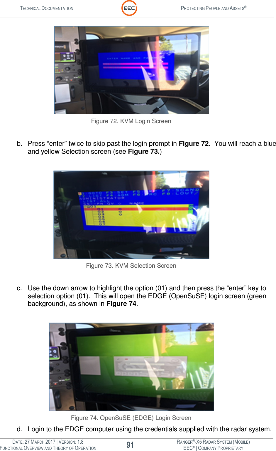
![TECHNICAL DOCUMENTATION PROTECTING PEOPLE AND ASSETS® DATE: 27 MARCH 2017 | VERSION: 1.8 90 RANGER®-X5 RADAR SYSTEM (MOBILE) FUNCTIONAL OVERVIEW AND THEORY OF OPERATION EEC® | COMPANY PROPRIETARY Figure 71. UPS Power On Sequence: 1. On the Emergency Stop Panel (see Figure 70, Point 6), ensure the Main Breaker (CB1) is in the [ON] position. 2. On the Emergency Stop Panel (see Figure 70, Point 7), ensure the Pedestal Breaker (CB2) is in the [ON] position. 3. On the Radar System UPS (see Figure 71, Point 1), press and hold the power button until the UPS power on. 4. Wait for the Power Distribution and Control Unit (see paragraph 1.1.6) to power on (approximately 2 minutes). 5. Press and hold the E-Stop Reset Button (see Figure 70, Point 1) for 2-3 seconds, then release. When the pedestal is initially powered on it will begin a warm-up and alignment process. The pedestal will rotate in azimuth as well as move up and down in elevation following a pre-programmed homing sequence. At the end of the homing process, the pedestal will rotate in azimuth until it reaches its home position, which is a variable position. The pedestal may pause at this position for a brief moment. 6. Ensure the power to the system is active by checking the various components in the Control Cabinet and verifying the lights (see Figure 70, Point 3, 4, and 5) are illuminated. a. Ensure the KVM monitor displays the blue and magenta login screen (see Figure 72, below.)](https://usermanual.wiki/Enterprise-Electronics/RANGERX5.User-Manual-Overview-Theory-Part-4/User-Guide-3348739-Page-30.png)
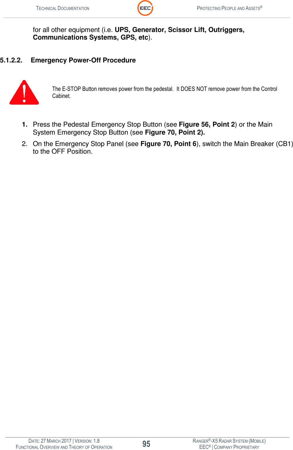
![TECHNICAL DOCUMENTATION PROTECTING PEOPLE AND ASSETS® DATE: 27 MARCH 2017 | VERSION: 1.8 94 RANGER®-X5 RADAR SYSTEM (MOBILE) FUNCTIONAL OVERVIEW AND THEORY OF OPERATION EEC® | COMPANY PROPRIETARY system. EDGE will update the latitude and longitude of the radar system based on input from the GPS / Compass unit. Please allow five to ten minutes for this process to complete. 3. After the latitude and longitude are updated and when the EDGE system has received enough information to determine “True North,” the antenna will automatically realign itself to “True North” and it will be ready for operational use. Please note, the radar can be operated after initial HOMING of the antenna is complete. However, the EDGE display for weather and other data will not be aligned with “True North” and therefore, their positions on the map will not be in the proper location relative to North. 5.1.2. Power-Off Procedure / System Shutdown For the safety of the maintenance personnel, they MUST complete the following system power off sequence before attempting any maintenance procedures. The complexities and design of the Ranger-X5 radar system requires training for personnel that will operate and maintain the radar system. The various components in the radar system will require the power switches and circuit breakers to be in the [OFF] position before performing maintenance. 5.1.2.1. Normal Power-Off Procedure 1. Power Down (in sequence) the following items. a. EDGE Local Host Computer (see Figure 8, Point 5 for switch location) b. IQ2-Digital Signal Processor (see Figure 6, Point 1 for switch location) c. RCU Computer (see Figure 5, Point 1 for switch location) d. UPS System (Figure 71, Point 1), press and hold the power button until the UPS powers off. 2. On the Emergency Stop Panel (see Figure 70, Point 7), switch the Pedestal Breaker (CB2) to the [OFF] position. 3. On the Emergency Stop Panel (see Figure 70, Point 6), switch the Main Breaker (CB1) to the [OFF] position. 4. Refer to Appropriate Vendor Documentation for shutdown and tear down procedures](https://usermanual.wiki/Enterprise-Electronics/RANGERX5.User-Manual-Overview-Theory-Part-4/User-Guide-3348739-Page-34.png)