Enterprise Electronics RANGERX5 Ranger-X5 RADAR User Manual Overview Theory Part 1
Enterprise Electronics Corporation Ranger-X5 RADAR Overview Theory Part 1
UserManual.wiki
>
Enterprise Electronics
>
RANGERX5 User Manual
>
User Manual Overview Theory Part 1
Contents
1.
User Manual Troubleshooting Maintenance Calibration Part 1
2.
User Manual Troubleshooting Maintenance Calibration Part 2
3.
User Manual Overview Theory Part 2
4.
User Manual Overview Theory Part 1
5.
User Manual Overview Theory Part 3
6.
User Manual Overview Theory Part 4
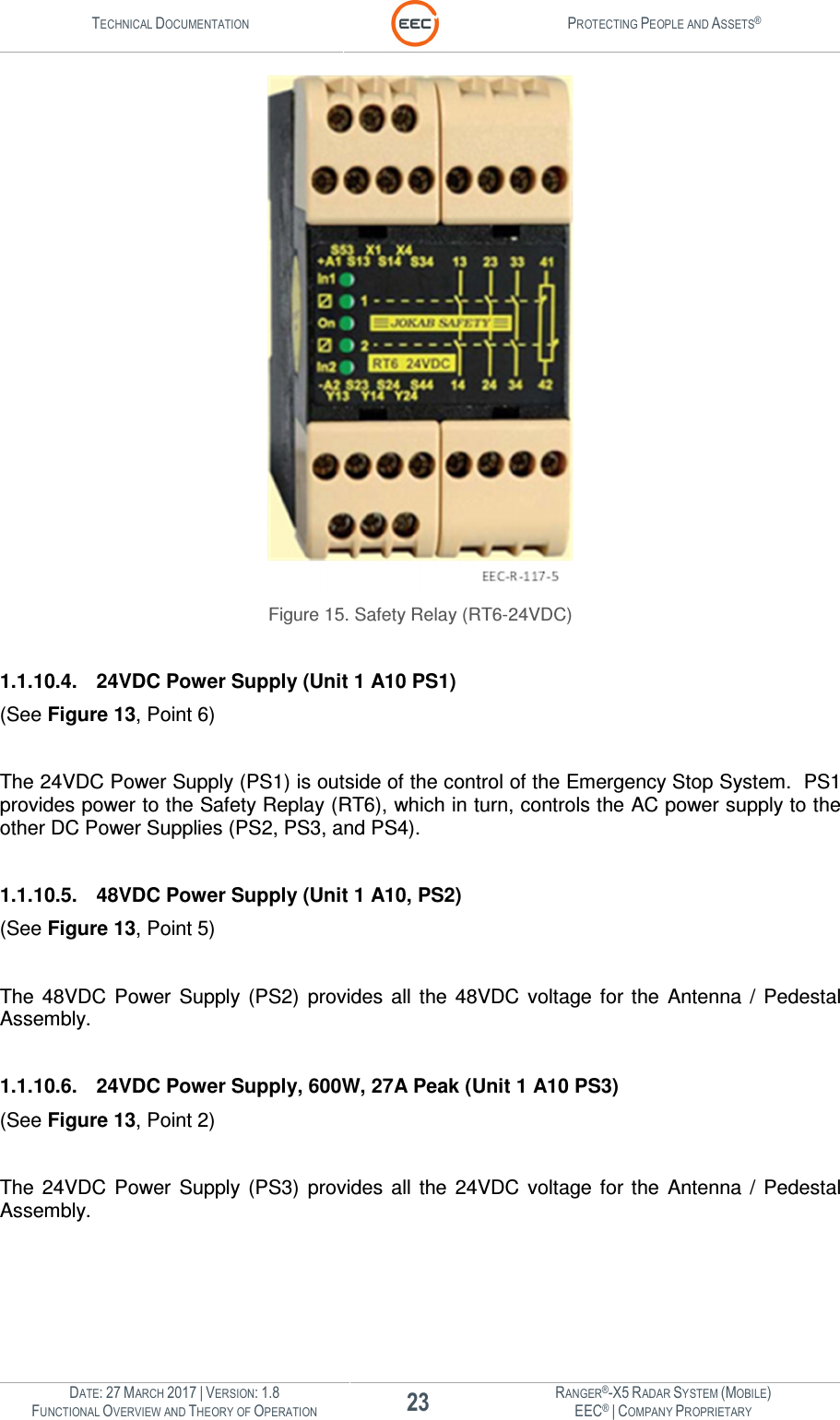
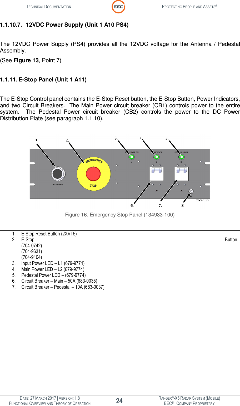
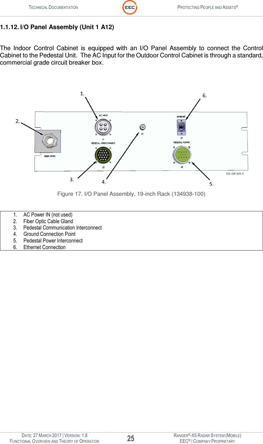
User Manual Overview Theory Part 1
Navigation menu
Upload a User Manual
Namespaces
Wiki Guide
HTML
PDF
Info
Views
User Manual
Discussion / Help
Navigation