Enterprise Electronics RANGERX5 Ranger-X5 RADAR User Manual Overview Theory Part 1
Enterprise Electronics Corporation Ranger-X5 RADAR Overview Theory Part 1
Contents
User Manual Overview Theory Part 1

®
Enterprise Electronics Corporation
T
ECHNICAL
D
OCUMENTATION
S
ET
O
PERATIONS AND
T
ECHNICAL
M
ANUAL
RANGER
®
X5
F
UNCTIONAL
O
VERVIEW AND
T
HEORY OF
O
PERATIONS
DESIGNED AND MANUFACTURED FOR:
MOBILE
CONFIGURATIONS
SECTION 1
J
OB
9819
EEC • 128 SOUTH INDUSTRIAL BOULEVARD • ENTERPRISE, ALABAMA 36330
TELEPHONE (334) 347-3478 • FAX (334) 393-4556 • www.eecradar.com

Official Enterprise Electronics Corporation (EEC
) Indemnification Clause
The technical data and information (hereinafter “technical data”) contained herein is highly confidential and proprietary in nature and is the sole
and exclusive intellectual property of the Enterprise Electronics Corporation ("EEC"). Any company, organization, entity or individual who seeks
to benefit from the use of this technical data (“User”) agrees to hold said information in strict confidence. User agrees that, unless required by
law, it shall not disclose or make the technical data available in any form to a third party without the specific express written consent of EEC with
regard to each such third party. User agrees to take all necessary steps to ensure that Intellectual Property is not disclosed or distributed by its
Directors, Officers, employees, representatives or agents in violation of this condition.
The User of the technical data contained herein agrees to defend (using counsel of EEC’s choosing), indemnify and hold harmless EEC, its
Directors, Officers and its employees, parent company, affiliate companies and/or subsidiaries, its successors and assigns, customers and users
of its Product(s) against all suits at law or in equity and from damages, claims and demands arising out of the death or injury to any person or
damage of any kind to User's Directors, Officers, employees, agents or property as a result of User's use, misuse, assumptions or interpretations
of the technical data contained herein.
EEC has made its best effort to offer the most current, correct, and clearly expressed information possible. Nevertheless, inadvertent errors in
information may occur. In particular, but without limitation to the above, EEC disclaims any responsibility for typographical errors or punctuation
errors contained herein.
EEC
®
is a registered Trademark of EEC.
EEC PROTECTING PEOPLE AND ASSETS
is a registered Trademark of EEC
RANGER
is a registered Trademark of EEC
TELESPACE
®
is a registered Trademark of EEC
EDGE is a Trademark of EEC.
Encoded Transmitted Signal In A Simultaneous Dual Polarization Weather System
United States Patent
US 7,439,899
Phase Shifted Transmitted Signals In A Simultaneous dual Polarization Weather System
United States Patent
US 7,551,123
Simultaneous Dual Polarization Radar System with Optical Communications Link
United States Patent
US 7,760,129
Simultaneous dual polarization radar systems offered by EEC are covered by one or more of the follow patents:
United States Patents
US 6,859,163 B2 (Inv-1)
US 6,803,875 B1 (Inv-2)
US 7,049,997 (Inv-3)
Foreign Patents
1200500266/13041 (OAPI African Organization) (Inv-1)
200501316/009250 (EA Eurasia) (Inv-1)
13694 (OAPI African Organization) (Inv-3)
2394254 (Russia) (Inv-3)
Simultaneous Dual Polarization Radar System Inv-2
Patented under European patent number 1608997
Various additional domestic and international patents have been applied for.
Validity Date: 24 September 2015
FCC Part 15.19 Warning Statement- (Required for all Part 15 devices)
THIS DEVICE COMPLIES WITH PART 15 OF THE FCC RULES. OPERATION IS SUBJECT TO THE FOLLOWING
TWO CONDITIONS: (1) THIS DEVICE MAY NOT CAUSE HARMFUL INTERFERENCE, AND (2) THIS DEVICE
MUST ACCEPT ANY INTERFERENCE RECEIVED, INCLUDING INTERFERENCE THAT MAY CAUSE
UNDESIRED OPERATION.
FCC Part 15.21 Warning Statement
NOTE: THE GRANTEE IS NOT RESPONSIBLE FOR ANY CHANGES OR MODIFICATIONS NOT EXPRESSLY
APPROVED BY THE PARTY RESPONSIBLE FOR COMPLIANCE. SUCH MODIFICATIONS COULD VOID THE
USER’S AUTHORITY TO OPERATE THE EQUIPMENT.
FCC Part 15.105(b) Warning Statement- (ONLY Required for 15.109-JBP devices)
NOTE: This equipment has been tested and found to comply with the limits for a Class B digital device, pursuant to
part 15 of the FCC Rules. These limits are designed to provide reasonable protection against harmful interference in
a residential installation. This equipment generates uses and can radiate radio frequency energy and, if not installed
and used in accordance with the instructions, may cause harmful interference to radio communications. However,
there is no guarantee that interference will not occur in a particular installation. If this equipment does cause harmful
interference to radio or television reception, which can be determined by turning the equipment off and on, the user
is encouraged to try to correct the interference by one or more of the following measures:
• Reorient or relocate the receiving antenna.
• Increase the separation between the equipment and receiver.
• Connect the equipment into an outlet on a circuit different from that to which the receiver is connected.
• Consult the manufacturer or an experienced radio/TV technician for help.
FCC Part 2.1091 Radiation Safety Warning
NOTE: This equipment complies with the FCC RF radiation exposure limits set forth for an uncontrolled
environment. This equipment should be installed and operated with a minimum distance of 22.43m between the
radiator and any part of your body.

DATE: 27 MARCH 2017 | VERSION: 1.8
i
RANGER
®
-X5 RADAR SYSTEM (MOBILE)
F
UNCTIONAL
O
VERVIEW AND
T
HEORY OF
O
PERATION
EEC
®
|
C
OMPANY
P
ROPRIETARY
Revision Information
REVISION DATE MODIFICATION
1.0 15 November 2014 Initial Version
1.1 3 February 2015 Updated with latest technical changes per ECNs
1.2 9 September 2015 Updated with latest changes.
Added the INDOOR Cabinet to the manuals.
1.3 7 April 2016 Updated information and graphics for pedestal section.
1.4N 31 October 2016 Update for NBC TRUCK Configurations – BRANCH VERSION
1.5A 6 Feb 2017 Pre-Delivery Version for J9819 – part numbers not yet updated.
1.6 14 Feb 2017 Added FCC Disclaimer and Updated ALL Part Numbers
1.7 15 March 2017 Updated FCC RF exposure statements antenna gains
1.8 27 March 2017 Updated images for Transmitter Control Assembly

DATE: 27 MARCH 2017 | VERSION: 1.8
ii
RANGER
®
-X5 RADAR SYSTEM (MOBILE)
F
UNCTIONAL
O
VERVIEW AND
T
HEORY OF
O
PERATION
EEC
®
|
C
OMPANY
P
ROPRIETARY
TABLE OF CONTENTS
1.
Control Components ................................................................................................................................. 9
1.1.
Control Components Housing (Unit 1) ................................................................................................ 9
1.1.1.
RCU with Serial Card (Unit 1 A1) ........................................................................................................ 11
1.1.1.1.
COBRA RCP Module .............................................................................................................................. 12
1.1.1.2.
COBRA HCI Module................................................................................................................................ 12
1.1.1.3.
COBRA LCI Module ................................................................................................................................ 12
1.1.2.
IQ2 Digital Signal Processor (Unit 1 A2)........................................................................................... 12
1.1.2.1.
IQ2 Host Computer (Unit 1 A2 A1) ..................................................................................................... 13
1.1.2.2.
IQ2 DSP PCIe Board (Unit 1 A2 A2) .................................................................................................. 14
1.1.2.3.
IQ2 Connector Panel (Unit 1 A2 A3) .................................................................................................. 14
1.1.3.
Keyboard Video Monitor (Unit 1 A3) .................................................................................................. 14
1.1.4.
EDGE Workstation (Unit 1 A4)............................................................................................................. 16
1.1.5.
16-Port Gigabit Ethernet Switch (Unit 1 A5) .................................................................................... 17
1.1.6.
Power Distribution Unit (Unit 1 A6) ..................................................................................................... 17
1.1.7.
Fiber-Optic Coupler (Unit 1 A7) ........................................................................................................... 18
1.1.8.
Fiber Optic Media Converter Assembly (Unit 1 A8) ...................................................................... 18
1.1.8.1.
7-Port Ethernet Switch with 1-Fiber Optic Port (Unit 1 A8 A1) .................................................. 19
1.1.8.2.
24VDC Power Supply (Unit 1 A8 PS1) ............................................................................................. 19
1.1.9.
UPS, 2000/1800 KVA (Unit 1 A9) ....................................................................................................... 19
1.1.10.
DC Power Distribution Plate (Unit 1 A10)......................................................................................... 20
1.1.10.1.
Lightning Protection Module (Unit 1 A10 A1) .................................................................................. 22
1.1.10.2.
Contactor, 3-Phase, 24VDC (Unit 1 A10 K1) .................................................................................. 22
1.1.10.3.
Safety Relay (Unit 1 A10 K2) ............................................................................................................... 22
1.1.10.4.
24VDC Power Supply (Unit 1 A10 PS1) ........................................................................................... 23
1.1.10.5.
48VDC Power Supply (Unit 1 A10, PS2) .......................................................................................... 23
1.1.10.6.
24VDC Power Supply, 600W, 27A Peak (Unit 1 A10 PS3) ........................................................ 23
1.1.10.7.
12VDC Power Supply (Unit 1 A10 PS4) ........................................................................................... 24
1.1.11.
E-Stop Panel (Unit 1 A11) ..................................................................................................................... 24
1.1.12.
I/O Panel Assembly (Unit 1 A12) ........................................................................................................ 25
2.
Antenna / Pedestal (Unit 2) ................................................................................................................... 29
2.1.
Pedestal Assembly (Unit 2 A1) ............................................................................................................ 30
2.1.1.
Azimuth Assembly (Unit 2 A1 A1) ....................................................................................................... 31
2.1.1.1.
Slip Ring with Fiber Optic Rotary Joint (Unit 2 A1 A1 A1) .......................................................... 32
2.1.1.2.
Actuator Unit (Unit 2 A1 A1 A2) ........................................................................................................... 33
2.1.2.
Elevation Assembly (Unit 2 A1 A2) .................................................................................................... 34
2.1.2.1.
Elevation Endcap Assembly (Unit 2 A1 A2 A1) .............................................................................. 35
2.1.2.2.
Actuator Unit (Unit 2 A1 A2 A1 A1) .................................................................................................... 36
2.1.3.
Elevation Driven Side Assembly (Unit 2 A1 A2 A2) ...................................................................... 37
2.1.3.1.
Servo Amplifier, 100V, 10A (Unit 2 A1 A2 A3) ............................................................................... 38
2.1.3.2.
Aquarian Servo Controller PCA (Unit 2 A1 A2 A4) ....................................................................... 39
2.1.3.3.
Regeneration Clamp (Unit 2 A1 A2 A5) ............................................................................................ 40
2.1.4.
Payload Support Assembly (Unit 2 A1 A3) ...................................................................................... 41
2.1.4.1.
Plenum Assembly (Unit 2 A1 A3 A1) ................................................................................................. 41
2.1.4.1.1.
IQ2 Intermediate Frequency Digitizer Assembly (Unit 2 A1 A3 A1 A1) .................................. 41
2.1.4.1.2.
I/O Control Module (Unit 2 A1 A3 A1 A3) ......................................................................................... 43
2.1.4.1.3.
Cold Plate, Weatherized (Unit 2 A1 A3 A1 A4) .............................................................................. 47
2.1.4.1.4.
8-Port Ethernet Switch (Unit 2 A1 A3 A1 A5) .................................................................................. 47
2.1.4.1.5.
Peltier Device Temperature Controller (Unit 2 A1 A3 A1 A6, A7) ............................................ 48
2.1.4.2.
Transceiver Assembly (Horizontal) (Unit 2 A1 A3 A2) ................................................................. 49
2.1.4.2.1.
500W Power Amplifier (Unit 2 A1 A3 A2 A1) .................................................................................. 50
2.1.4.2.2.
Horizontal UDC / Transmitter Control (Unit 2 A1 A3 A2 A2) ...................................................... 51
2.1.4.2.3.
Transceiver Power Supply Unit (Unit 2 A1 A3 A2 A3) ................................................................. 53
2.1.4.2.4.
Temperature / Humidity Sensor (Unit 2 A1 A3 A2 A4) ................................................................. 54
2.1.4.2.5.
Crossguide Coupler (Unit 2 A1 A3 A2 DC1) ................................................................................... 55
2.1.4.2.6.
3-Port Circulator (Unit 2 A1 A3 A2 HY1)........................................................................................... 55
2.1.4.2.7.
TR Limiter (Unit 2 A1 A3 A2 V1) ......................................................................................................... 56
2.1.4.3.
Transceiver Assembly (Vertical) (Unit 2 A1 A3 A3) ...................................................................... 56
2.1.4.3.1.
500W Power Amplifier (Unit 2 A1 A3 A3 A1) .................................................................................. 57

DATE: 27 MARCH 2017 | VERSION: 1.8
iii
RANGER
®
-X5 RADAR SYSTEM (MOBILE)
F
UNCTIONAL
O
VERVIEW AND
T
HEORY OF
O
PERATION
EEC
®
|
C
OMPANY
P
ROPRIETARY
2.1.4.3.2.
Vertical UDC / Transmitter Control (Unit 2 A1 A3 A3 A2) ........................................................... 57
2.1.4.3.3.
Transceiver Power Supply Unit (Unit 2 A1 A3 A3 A3) ................................................................. 57
2.1.4.3.4.
Temperature / Humidity Sensor (Unit 2 A1 A3 A3 A4) ................................................................. 57
2.1.4.3.5.
Crossguide Coupler (Unit 2 A1 A3 A3 DC1) ................................................................................... 58
2.1.4.3.6.
3-Port Circulator (Unit 2 A1 A3 A3 HY1)........................................................................................... 58
2.1.4.3.7.
TR Limiter (Unit 2 A1 A3 A3 V1) ......................................................................................................... 58
2.1.4.4.
Fluid Pump Assembly (Unit 2 A1 A3 A4) .......................................................................................... 58
2.1.4.5.
Weatherized Liquid Cooler (Unit 2 A1 A4 A6)................................................................................. 58
2.1.5.
V-Clamp Pedestal Assembly (Unit 2 A1 A4) ................................................................................... 59
2.1.6.
Pedestal Enclosure Plate Assembly (Unit 2 A1 A5)...................................................................... 60
2.1.6.1.
7-Port Ethernet Switch with 1-Fiber Optic Port (Unit 2 A1 A5 A1) ........................................... 60
2.1.6.2.
Servo Amplifier, 100V, 10A (Unit 2 A1 A5 A2) ............................................................................... 61
2.1.6.3.
Fiber Optic Coupler (Unit 2 A1 A5 A3) .............................................................................................. 61
2.1.6.4.
Aquarian Servo Controller PCA (Unit 2 A1 A5 A4) ....................................................................... 62
2.1.6.5.
Regeneration Clamp (Unit 2 A1 A5 A5) ............................................................................................ 62
2.2.
Antenna Assembly – 1 Meter Reflector (Unit 2 A2) ...................................................................... 63
3.
Radome (Unit 3) ....................................................................................................................................... 67
4.
System Theory of Operations .............................................................................................................. 71
4.1.
COBRA Software ..................................................................................................................................... 71
4.1.1.
BITE Page .................................................................................................................................................. 72
4.2.
Primary Power Supply and Distribution ............................................................................................ 76
4.3.
Interlock Circuitry ...................................................................................................................................... 78
4.3.1.
Hardware Interlocks................................................................................................................................. 78
4.3.2.
Software Interlocks .................................................................................................................................. 79
4.3.3.
Radiate Command ................................................................................................................................... 81
4.3.4.
IF to RF Signal Up and Down Conversion ....................................................................................... 81
4.3.5.
Fiber-Optic Rotary Joint ......................................................................................................................... 81
4.4.
Receiver Signal Flow .............................................................................................................................. 81
4.4.1.
IQ2-IFD ........................................................................................................................................................ 81
4.4.2.
IQ2-DSP ...................................................................................................................................................... 82
4.5.
Antenna Control ........................................................................................................................................ 82
4.5.1.
Angle Acquisition ...................................................................................................................................... 82
4.5.2.
Homing Sequence ................................................................................................................................... 82
4.6.
Communication Interface ....................................................................................................................... 83
4.6.1.
Radiation Safety ....................................................................................................................................... 85
5.
System Startup / Shutdown .................................................................................................................. 89
5.1.
Ranger-X5 Power Procedures ............................................................................................................. 89
5.1.1.
Radar Power-On Procedure ................................................................................................................. 89
5.1.1.1.
Verification of Alignment to True North ............................................................................................. 93
5.1.2.
Power-Off Procedure / System Shutdown ....................................................................................... 94
5.1.2.1.
Normal Power-Off Procedure ............................................................................................................... 94
5.1.2.2.
Emergency Power-Off Procedure ....................................................................................................... 95
TABLE OF FIGURES
Figure 1. 1.8-Meter Ranger-X5 Variant .............................................................................................................................. 4
Figure 2. Control Cabinet (Climate Controlled) – 137043-100 (Front) ..................................................................... 9
Figure 3. Control Cabinet (Climate Controlled) – 137043-100 (Rear) .................................................................... 10
Figure 4. Control Cabinet (Climate Controlled) – 137043-100 .................................................................................. 10
Figure 5. Radar Control Unit (133784-100) ..................................................................................................................... 11
Figure 6. IQ2-DSP Computer (134119-100) ................................................................................................................... 13
Figure 7. Keyboard, Video Monitor (132507-100) ......................................................................................................... 15
Figure 8. EDGE Workstation, Rack Mount ...................................................................................................................... 16
Figure 9. 16-Port Gigabit Ethernet Switch (JGS816) ................................................................................................... 17
Figure 10. Power Distribution and Control Unit (VMR-8HD20-2) ............................................................................. 17
Figure 11. Fiber Optic Media Converter Assembly (133116-100) ........................................................................... 18

DATE: 27 MARCH 2017 | VERSION: 1.8
iv
RANGER
®
-X5 RADAR SYSTEM (MOBILE)
F
UNCTIONAL
O
VERVIEW AND
T
HEORY OF
O
PERATION
EEC
®
|
C
OMPANY
P
ROPRIETARY
Figure 12. UPS, Powerware Model 9130, (PW9130I2000R-XL) ............................................................................. 19
Figure 13. DC Power Distribution Plate (134932-101) ................................................................................................ 21
Figure 14. Contactor (226-0516) ........................................................................................................................................ 22
Figure 15. Safety Relay (RT6-24VDC) ............................................................................................................................. 23
Figure 16. Emergency Stop Panel (134933-100) .......................................................................................................... 24
Figure 17. I/O Panel Assembly, 19-inch Rack (134938-100) .................................................................................... 25
Figure 18. Antenna / Pedestal Unit – 1.8 Meter Reflector (135955-101) .............................................................. 29
Figure 19. Pedestal Unit (135885-100)............................................................................................................................. 30
Figure 20. Azimuth Assembly (135887-100)................................................................................................................... 31
Figure 21. Slip Ring Assembly (134523-100) ................................................................................................................. 32
Figure 22. Actuator Unit (135782-100) ............................................................................................................................. 33
Figure 23. Elevation Assembly (135952-100) ................................................................................................................ 34
Figure 24. Elevation Driven Side Assembly (135539-100) ........................................................................................ 35
Figure 25. Actuator Unit (135782-100) ............................................................................................................................. 36
Figure 26. Elevation Endcap Assembly (134775-100) ................................................................................................ 37
Figure 27. Servo Amplifier (135534-100) ......................................................................................................................... 38
Figure 28. Aquarian Servo Controller (134839-103) .................................................................................................... 39
Figure 29. Regeneration Clamp (1000-327) ................................................................................................................... 40
Figure 30. Payload Support Assembly (135953-100) .................................................................................................. 41
Figure 31. Plenum Assembly (135540-100) ................................................................................................................... 41
Figure 32. IQ2-IFD (134066-101) ....................................................................................................................................... 42
Figure 33. I/O Control Module (135964-100) .................................................................................................................. 43
Figure 34. Ethernet 16-Channel Discrete I/O Module (132849-100) - Position ................................................... 44
Figure 35. Ethernet 16-Channel Discrete I/O Module (132849-100) – Connections ......................................... 44
Figure 36. Ethernet 12-Channel Analog I/O Module (132839-100) – Position .................................................... 45
Figure 37. Ethernet 12-Channel Analog I/O Module (132839-100) – Position .................................................... 46
Figure 38. Cold Plate (CP-3354) ........................................................................................................................................ 47
Figure 39. 8-Port Ethernet Switch (Spider 8TX) ............................................................................................................ 47
Figure 40. Peltier Temperature Controller (TC-48-20) ................................................................................................ 48
Figure 41. Horizontal Transceiver Assembly (135895-100) ...................................................................................... 49
Figure 42. 500W Power Amplifier (134325-500) ........................................................................................................... 50
Figure 43. UDC / Transmitter Control Assembly (135898-100) – Horizontal ....................................................... 51
Figure 44. UDC / Transmitter Control (135898-100) .................................................................................................... 52
Figure 45. Signal Generator (LMS-103) ........................................................................................................................... 53
Figure 46. Transceiver Power Supply (134728-100) ................................................................................................... 54
Figure 47. Temperature Humidity Sensor (134951-100) ............................................................................................ 55
Figure 48. Crossguide Coupler (609870) ......................................................................................................................... 55
Figure 49. 3-Port Circulator (135862-100) ....................................................................................................................... 55
Figure 50. TR Limiter (133723-100) .................................................................................................................................. 56
Figure 51. Vertical Transceiver Assembly (135891-100) ............................................................................................ 57
Figure 52. Fluid Pump Assembly (135118-100) ............................................................................................................ 58
Figure 53. Weatherized Liquid Cooler (LC-3356) ......................................................................................................... 59
Figure 54. V-Clamp Pedestal Assembly (135892-100) ............................................................................................... 59
Figure 55. Pedestal Enclosure Plate Assembly ............................................................................................................. 60
Figure 56. Ethernet Switch (EDS-308-M-SC-T) ............................................................................................................. 60
Figure 57. Servo Amplifier (135914-100) ......................................................................................................................... 61
Figure 58. Fiber Optic Coupler (FSP-SC-BR) ................................................................................................................ 62
Figure 59. Aquarian Servo Controller (134839-103) .................................................................................................... 62
Figure 60. Regeneration Clamp (1000-237) ................................................................................................................... 62
Figure 94. 1.8 Meter Antenna .............................................................................................................................................. 63
Figure 95.Ranger-X5 COBRA Software Architecture .................................................................................................. 72
Figure 96. BITE Command / Response Display ............................................................................................................ 74
Figure 97. BITE Commands and Function with Associated Limits .......................................................................... 74
Figure 98. Network Monitor Screen ................................................................................................................................... 75
Figure 99. Radar System Power Distribution.................................................................................................................. 77
Figure 100.UDC / Transmitter Control .............................................................................................................................. 80
Figure 101.Ranger-X5 Communication ............................................................................................................................ 85
Figure 102. Radiation Hazard Zone – General Population ........................................................................................ 86
Figure 106. Emergency Stop Panel ................................................................................................................................... 89
Figure 107. UPS ....................................................................................................................................................................... 90
Figure 108. KVM Login Screen ........................................................................................................................................... 91
Figure 109. KVM Selection Screen .................................................................................................................................... 91

DATE: 27 MARCH 2017 | VERSION: 1.8
v
RANGER
®
-X5 RADAR SYSTEM (MOBILE)
F
UNCTIONAL
O
VERVIEW AND
T
HEORY OF
O
PERATION
EEC
®
|
C
OMPANY
P
ROPRIETARY
Figure 110. OpenSuSE (EDGE) Login Screen .............................................................................................................. 91
Figure 111. EDGE A to EDGE B Script ICON ................................................................................................................ 92
Figure 112. EDGE Communications Window ................................................................................................................. 92
Figure 113. EDGE Application Icon ................................................................................................................................... 93
Figure 114. EDGE Control Menu ........................................................................................................................................ 93
TABLE OF TABLES
Table 1. EDGE Computer Characteristics ....................................................................................................................... 16
Table 2. BITE Display Naming Convention ..................................................................................................................... 73

T
ECHNICAL
D
OCUMENTATION
P
ROTECTING
P
EOPLE AND
A
SSETS
®
D
ATE
:
27
M
ARCH
2017
|
V
ERSION
:
1.8
1
R
ANGER
®
-
X5
R
ADAR
S
YSTEM
(M
OBILE
)
F
UNCTIONAL
O
VERVIEW AND
T
HEORY OF
O
PERATION
EEC
®
|
C
OMPANY
P
ROPRIETARY
I
NTRODUCTION
S
YSTEM
I
NTRODUCTION AND
O
VERVIEW

T
ECHNICAL
D
OCUMENTATION
P
ROTECTING
P
EOPLE AND
A
SSETS
®
D
ATE
:
27
M
ARCH
2017
|
V
ERSION
:
1.8
2
R
ANGER
®
-
X5
R
ADAR
S
YSTEM
(M
OBILE
)
F
UNCTIONAL
O
VERVIEW AND
T
HEORY OF
O
PERATION
EEC
®
|
C
OMPANY
P
ROPRIETARY
This page intentionally blank.

T
ECHNICAL
D
OCUMENTATION
P
ROTECTING
P
EOPLE AND
A
SSETS
®
D
ATE
:
27
M
ARCH
2017
|
V
ERSION
:
1.8
3
R
ANGER
®
-
X5
R
ADAR
S
YSTEM
(M
OBILE
)
F
UNCTIONAL
O
VERVIEW AND
T
HEORY OF
O
PERATION
EEC
®
|
C
OMPANY
P
ROPRIETARY
The Enterprise Electronics Corporation (EEC) Ranger-X5 radar system is a new generation, X-
band (3 cm), Adaptive Polarization Doppler Weather Surveillance Radar that fills the gap between
high-cost, high-power traditional radar systems and the passive ground-station weather sensors.
The system uses relatively low power solid-state transmitters and pulse compression technology
to attain nearly the same performance capabilities of much more expensive traditional radar
systems. The Ranger-X5 employs Adaptive Dual Polarization (ADP) techniques to allow
Alternating or Simultaneous Dual Polarization capability with total control over the transmission
polarization state using dual independent coherent transmitters.
The entire Ranger-X5 design concept emphasizes precision, stability, reliability, and value using
proven solid-state technology combined with the most advanced motion control system ever
conceived for weather radar. The sealed, lubricated for life, mechanical drive system in the
Ranger-X5 has an MTBF in excess of 180,000 hours without the need for routine maintenance
or lubrication. The motion system provides extremely high torque to weight ratios for outdoor
operation and greater than 40 arc-second position accuracy.
Advanced configurations and networks of systems are available that meet all of the requirements
for special missions, such as aviation or hydrological forecasting applications.
The flexible architecture and system design facilitates automatic remote operations, ensures
minimal maintenance costs, and provides maximum configurability to meet specialized customer
needs. The Ranger-X5 is designed for continuous (24 hours/day), unattended operations at
remote locations, providing the full suite of polarimetric radar data for local single-site operations,
as a member of a network with predefined product contributions or, as the manager of a network
of remote users providing specific radar products to suite the individual user’s needs.
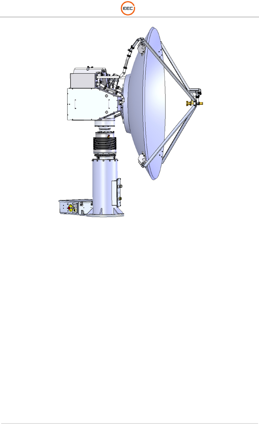
The Ranger-X5 radar system is a lightweight, high performance system designed for tactical
grade deployments on a wide variety of fixed and mobile platforms. This densely packed system
provides stability, stiffness, position accuracy and raw power directly coupled to the payload.
The 1-meter variant shown in Figure 1 is capable of supporting full operation in sustained winds
up to 75 mph, and with wind gusts to 90 mph. To deliver radar and motor cooling, the system
provides for water-cooling using naval shipboard cooling techniques.
T
ECHNICAL
D
OCUMENTATION
P
ROTECTING
P
EOPLE AND
A
SSETS
®
D
ATE
:
27
M
ARCH
2017
|
V
ERSION
:
1.8
4
R
ANGER
®
-
X5
R
ADAR
S
YSTEM
(M
OBILE
)
F
UNCTIONAL
O
VERVIEW AND
T
HEORY OF
O
PERATION
EEC
®
|
C
OMPANY
P
ROPRIETARY
Figure 1. 1.8-Meter Ranger-X5 Variant
The standard Ranger-X5 system configuration includes an elevation over azimuth pedestal
providing on-board, environmentally sealed, and controlled electronics housing for the
transmitters, receivers, and signal digitizer in conjunction with a NEMA 4 grade environmentally
controlled ground interface enclosure. The ground interface contains the system power supplies,
EEC IQ2 signal processor, Local Control Interface (LCI) station, Radar Control Unit (RCU)
Computer running EEC COBRA software, EEC EDGE software system workstation, and
associated communication interfaces. The ground interface enclosure is not required with
customer furnished facilities.
The standard configuration uses two 500-Watt transmitters located on the pedestal above the
elevation rotational axis to support Dual Polarization operation. This design eliminates the need
for waveguide switches, waveguide rotary joints, or a power splitter, allowing for complete
diversity in H/V measurement schemes and minimum path loss in both the transmission and
reception path.
The radar system provides standard precipitation intensity, turbulence, and velocity modes of
analysis with extremely high precision in all modes of operation. Normal radar control and data
processing utilizes the EDGE Radar Control and Analysis Software. A separate technical
manuals describes the functions of EDGE.
The transmitter provides a 500W peak RF power pulse (in each channel) with an adjustable pulse
width from 0.2 and 100.0 microseconds (µs), providing excellent weather detection at range in all
modes. The transmitter radiates in staggered Pulse Repetition Frequency (PRF) modes at 3:2,
4:3, or 5:4 ratio allowing dual PRF sampling by the digital signal processor to produce maximum
unambiguous velocities of up to ≥90 meters/second.
The EEC IQ2-IFD Intermediate Frequency Digitizer ingests and digitizes the received radar return
in 16-bit resolution. The receiver design utilizes state-of-the-science components to optimize

T
ECHNICAL
D
OCUMENTATION
P
ROTECTING
P
EOPLE AND
A
SSETS
®
D
ATE
:
27
M
ARCH
2017
|
V
ERSION
:
1.8
5
R
ANGER
®
-
X5
R
ADAR
S
YSTEM
(M
OBILE
)
F
UNCTIONAL
O
VERVIEW AND
T
HEORY OF
O
PERATION
EEC
®
|
C
OMPANY
P
ROPRIETARY
detection sensitivity, bandwidth, dynamic range, measurement accuracy, and useful life.
The IQ2-IFD converts the analog receiver IF signals into the digital domain. The IQ2-DSP Digital
Signal Processor receives the digitized Inphase / Quadranture (I/Q) data via the PCI receiver
card. The I/Q data stream is pre-processed and polar rays of meteorological moments are
generated. The ray data is sent via a 1Gbit TCP/IP connection to the IQ2-DSP Signal Processor
for storage and further processing. The IQ2 design optimizes detection sensitivity, bandwidth,
dynamic range, measurement accuracy, and useful life.
The IQ2-DSP is the central data processing point for the radar. The IQ2-DSP is an advanced
scientific computer system utilizing the Linux operating system and employs advanced
scientifically validated algorithms. The standard mode of operation is the proven pulse-pair
method of Doppler processing to produce the standard data moments of Uncorrected Reflectivity
(U), Corrected Reflectivity (ZH), Vertical Reflectivity (ZV), Velocity (V), and Spectrum Width (W).
In addition to the standard base Moments, the system provides the Polarimetric Base Moments
Differential Reflectivity (ZDR), Differential Phase (ΦDP), Specific Differential Phase (KDP),
Correlation Coefficient (ρHV), and Linear Depolarization Ratio (LDR), (where applicable). The
derived moment of rainfall (R) is also included.
General system control utilizes the standard EEC Radar Control Unit (RCU). The RCU is used
to correlate and process BITE information from the various modules and procedures, control the
antenna pedestal operational parameters and perform basic radar control. The RCU integrates
closely with the IQ2 Digital Receiver and IQ2 Digital Signal Processor, communicating by
standard Ethernet Protocol.
The radar system design allows for easy maintenance and has a manually selectable
local/remote mode to permit maintenance personnel to gain local control of the radar system.
Local control is implemented on a Local Control Interface (LCI) Display using a system of menus
and status screens. With the automatic calibration functions and easily accessible system test
points, any necessary system testing, calibration, or repair is easily accomplished with minimum
down time.

T
ECHNICAL
D
OCUMENTATION
P
ROTECTING
P
EOPLE AND
A
SSETS
®
D
ATE
:
27
M
ARCH
2017
|
V
ERSION
:
1.8
6
R
ANGER
®
-
X5
R
ADAR
S
YSTEM
(M
OBILE
)
F
UNCTIONAL
O
VERVIEW AND
T
HEORY OF
O
PERATION
EEC
®
|
C
OMPANY
P
ROPRIETARY
This page intentionally blank.

T
ECHNICAL
D
OCUMENTATION
P
ROTECTING
P
EOPLE AND
A
SSETS
®
D
ATE
:
27
M
ARCH
2017
|
V
ERSION
:
1.8
7
R
ANGER
®
-
X5
R
ADAR
S
YSTEM
(M
OBILE
)
F
UNCTIONAL
O
VERVIEW AND
T
HEORY OF
O
PERATION
EEC
®
|
C
OMPANY
P
ROPRIETARY
C
HAPTER
1
C
ONTROL
C
ABINET
(U
NIT
1)

T
ECHNICAL
D
OCUMENTATION
P
ROTECTING
P
EOPLE AND
A
SSETS
®
D
ATE
:
27
M
ARCH
2017
|
V
ERSION
:
1.8
8
R
ANGER
®
-
X5
R
ADAR
S
YSTEM
(M
OBILE
)
F
UNCTIONAL
O
VERVIEW AND
T
HEORY OF
O
PERATION
EEC
®
|
C
OMPANY
P
ROPRIETARY
This page intentionally blank.
T
ECHNICAL
D
OCUMENTATION
P
ROTECTING
P
EOPLE AND
A
SSETS
®
D
ATE
:
27
M
ARCH
2017
|
V
ERSION
:
1.8
9
R
ANGER
®
-
X5
R
ADAR
S
YSTEM
(M
OBILE
)
F
UNCTIONAL
O
VERVIEW AND
T
HEORY OF
O
PERATION
EEC
®
|
C
OMPANY
P
ROPRIETARY
1.
Control Components
The Control Components are mounted in special configurations. The layout is significantly
different that cabinet mounted versions of the Ranger-X5 systems.
1.1. Control Components Housing (Unit 1)
The Ranger-X5 Control Cabinet houses the Keyboard Video Monitor (KVM), Signal Processor,
and Radar Control Unit, Local UPS, Power Controller, DC Power Supplies and the
Communications Interface for the radar system. The components are located in a rack and
connected to the pedestal and transceiver units via a fiber-optic communications connection and
DC power cables.
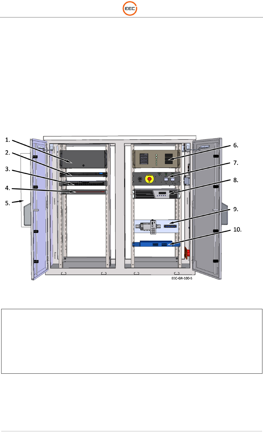
Figure 2. Control Cabinet (Climate Controlled) – 137043-100 (Front)
1.
EDGE Workstation
2. Keyboard Video Monitor (A3) – 132507-100
3. Radar Control Unit (A1) – 133784-100
4. Power Distribution Unit (A6) – VMR-8HD20-2
5. Air Conditioning Unit
6. IQ2 Digital Signal Processor (A2) – 134119-100
7. E-Stop Panel Assembly (A12) – 134933-100
8. UPS, 2000/1800 KVA (A9) – PW91302000R-XL
9. FO Media Converter Assembly (A8) – 133116-100
10. 16-Port Ethernet Switch (A5) – JGS516
T
ECHNICAL
D
OCUMENTATION
P
ROTECTING
P
EOPLE AND
A
SSETS
®
D
ATE
:
27
M
ARCH
2017
|
V
ERSION
:
1.8
10
R
ANGER
®
-
X5
R
ADAR
S
YSTEM
(M
OBILE
)
F
UNCTIONAL
O
VERVIEW AND
T
HEORY OF
O
PERATION
EEC
®
|
C
OMPANY
P
ROPRIETARY
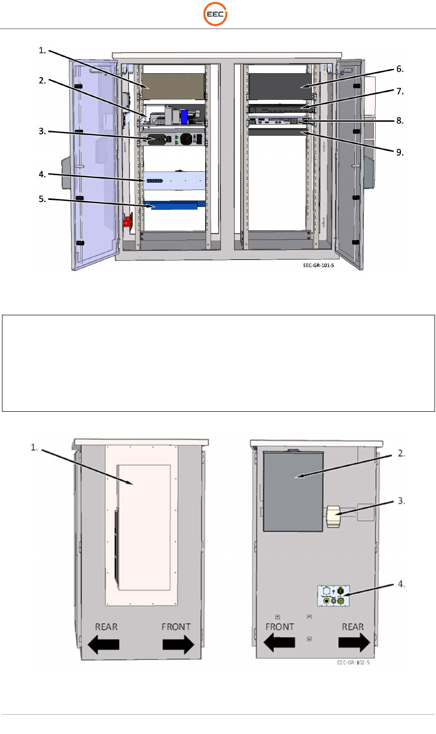
Figure 3. Control Cabinet (Climate Controlled) – 137043-100 (Rear)
1.
IQ2 Digital Signal Processor
(A2)
–
134119
-
100
2. DC Power Distribution Plate (A13) – 134932-100
3. UPS, 2000/1800 KVA (A9) – PW91302000R-XL
4. FO Media Converter Assembly (A8) – 133116-100
5. 6-Port Ethernet Switch (A5) – JGS516
6. EDGE Workstation
7. Keyboard Video Monitor (A3) – 132507-100
8. Radar Control Unit (A1) – 133784-100
9. Power Distribution Unit (A6) – VMD-8HD20-2
Figure 4. Control Cabinet (Climate Controlled) – 137043-100
T
ECHNICAL
D
OCUMENTATION
P
ROTECTING
P
EOPLE AND
A
SSETS
®
D
ATE
:
27
M
ARCH
2017
|
V
ERSION
:
1.8
11
R
ANGER
®
-
X5
R
ADAR
S
YSTEM
(M
OBILE
)
F
UNCTIONAL
O
VERVIEW AND
T
HEORY OF
O
PERATION
EEC
®
|
C
OMPANY
P
ROPRIETARY
1.
Air Conditioning Unit
2. A/C Circuit Breaker Box
3. GFCI Power Outlet
4. I/O Panel Assembly (135204-100)
1.1.1. RCU with Serial Card (Unit 1 A1)
The RCU host computer is a Linux based standard industrial PC that physically converts to
Ethernet I/O slave modules to control and monitor radar hardware, using the open industrial
standard ModbusTCP for communications. The Radar Control Unit is loaded with Cobra
Software (See Section 3, RCU Cobra Software).
Implementation of command and control of the pedestal is over the Ethernet link from the Radar
Control Unit PC (COBRA Application software) all of the other components in the Control Cabinet
and the Pedestal Unit. The control of the azimuth and elevation servo is directly through an
Ethernet connection to the Servo Controller Assembly.
Position commands route to the Servo Controller from the COBRA software system based on
commands from either the Local Control Interface (LCI) or the remote host operator. A position
command invokes a command interpreter script in COBRA that sends the appropriate command
to the pre-loaded servo control module. The Servo Controller has an extensive standard
command and control set and an extended command set for use with radar servo systems.
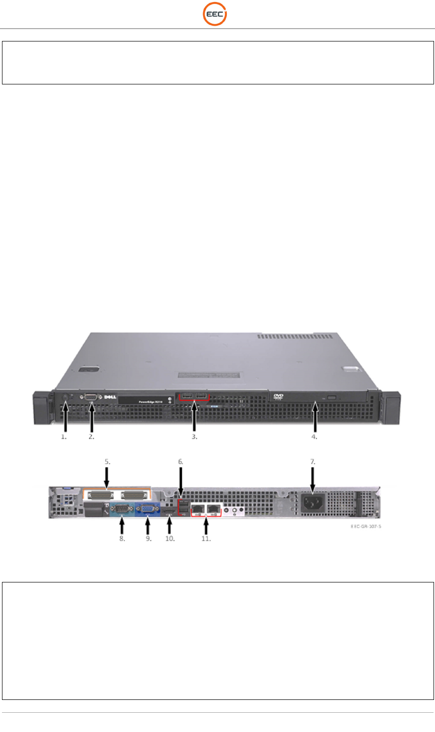
Figure 5. Radar Control Unit (133784-100)
1.
Power Switch
2. Front VGA Port
3. Front USB Ports (2)
4. DVD Drive
5. Synclink Ports (2) – (IQ2-DSP Connect)
6. Rear USB Ports (2) – (KVM Connect)
7. Power Connect
8. RS232 Port (Inclinometer) – (OPTIONAL)
9. VGA Port (KVM Connect)
10. eSATA Port
11.
Ethernet (2)
–
(Ethernet Switch)

T
ECHNICAL
D
OCUMENTATION
P
ROTECTING
P
EOPLE AND
A
SSETS
®
D
ATE
:
27
M
ARCH
2017
|
V
ERSION
:
1.8
12
R
ANGER
®
-
X5
R
ADAR
S
YSTEM
(M
OBILE
)
F
UNCTIONAL
O
VERVIEW AND
T
HEORY OF
O
PERATION
EEC
®
|
C
OMPANY
P
ROPRIETARY
1.1.1.1. COBRA RCP Module
The COBRA Radar Control Processor (RCP) module controls the radar hardware through a
series of coordinated and supervised hardware Analog and Digital control modules. These I/O
modules connect to the RCU by Ethernet. The Ethernet communication layer between the RCU
and the distributed modules is functionally isolated from any point beyond the RCU so there is
no danger to having a remote host attempt to communicate directly with the hardware control
modules.
The COBRA RCP software is hardware independent through a software abstraction layer. This
allows easy transition to other vendors and products based on availability and features
In order to assure accurate and complete time stamping of each command, response, and status,
each module comprising the RCU is synchronized using the Network Time Protocol (NTP).
Additionally, filters and other integrity checks within the RCU and associated software elements
ensure that any command, response, error message, or status message is appropriately logged
and repeated entries are avoided.
1.1.1.2. COBRA HCI Module
The COBRA HCI software module operates at the gateway between the RCP module and the
EEC EDGE Radar Host computer.
1.1.1.3. COBRA LCI Module
The Local Control Interface (LCI) module is a computer based local control and operator interface
to the COBRA program functions. In this configuration, the LCI runs on the same computer as
the COBRA software. The user display shares the standard commercial keyboard and video
monitor unit with the IQ2-DSP and EDGE Host computer.
The software communicates with various radar components through the COBRA application
software in order to provide user commands to the system and reflect control and status data to
the user. Such data includes but is not limited to azimuth and elevation position, power levels,
and voltage/current measurements. The ability to monitor the radar performance over Ethernet
connections provides the flexibility and opportunity to monitor the radar from virtually anywhere.
LCI presents the radar control information as familiar indicators and controls on the computer
screen as a virtual control panel. Common indicator styles include the LED, round gauges and
seven-segment digital readouts. Some indicators switch views when clicked. Interaction is
through the keyboard and touch pad.
1.1.2. IQ2 Digital Signal Processor (Unit 1 A2)
The IQ2 DSP consists of a PCIe card in a high-performance Host Computer used for signal
processing deployed in the Control Cabinet. This design of the computer and PCIe card ensures
the highest performance available, as well as for flexibility in adapting to various radar system
configurations. The DSP receives digital I/Q over the high-speed optical link from the IQ2-IFD,
passes this data to the high-speed server for moments processing.
T
ECHNICAL
D
OCUMENTATION
P
ROTECTING
P
EOPLE AND
A
SSETS
®
D
ATE
:
27
M
ARCH
2017
|
V
ERSION
:
1.8
13
R
ANGER
®
-
X5
R
ADAR
S
YSTEM
(M
OBILE
)
F
UNCTIONAL
O
VERVIEW AND
T
HEORY OF
O
PERATION
EEC
®
|
C
OMPANY
P
ROPRIETARY
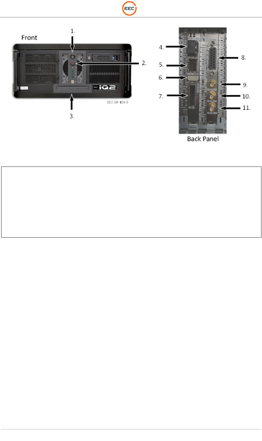
Figure 6. IQ2-DSP Computer (134119-100)
1.
Power Switch
2. Power Indicator
3. DVD Drive
4. J7 - Fiber-Optic Connect
5. J8 – Ethernet
6. J6 – Antenna Serial Anglers
7. J10 – PCIe Connect
8. J1 – GPIO
9. J2 – Waveform Generator (Primary)
10. J3 – Waveform Generator (Secondary)
11. J4 – Trigger Output
1.1.2.1. IQ2 Host Computer (Unit 1 A2 A1)
The IQ2-DSP Host Computer is equipped with a powerful, state-of-the-art, signal processor that
receives In-Phase and Quadrature (I/Q) data from the IQ2-IFD coming in real time. The Signal
Processor elaborates the real-time I/Q data to create the required single and dual polarization
meteorological moments.
The IQ2-DSP consists of a PCIe communications card plugged into a high-speed server. The
PCIe card receives the high-speed optical link from the IQ2-IFD, passes this data to the high-
speed server for the processing of meteorological moments, and provides additional interfaces
that may be required to support other radar-site systems.
The IQ2-DSP Host Computer processes the I/Q data stream, already broken into range-gate
intervals, with floating-point algorithms to provide all required moments. The server also provides
all the configuration and control signals to all of the components in the IQ2-DSP system.
The IQ2-DSP Host Computer is a Linux based standard industrial PC. The standard mode of
operation is the well-defined, proven pulse-pair method of Doppler radar data processing that
produces the standard data moments of:
• Uncorrected Reflectivity (U)
• Corrected Reflectivity (ZH)
• Vertical Reflectivity (Zv)
• Velocity (V)
• Spectrum Width (W)

T
ECHNICAL
D
OCUMENTATION
P
ROTECTING
P
EOPLE AND
A
SSETS
®
D
ATE
:
27
M
ARCH
2017
|
V
ERSION
:
1.8
14
R
ANGER
®
-
X5
R
ADAR
S
YSTEM
(M
OBILE
)
F
UNCTIONAL
O
VERVIEW AND
T
HEORY OF
O
PERATION
EEC
®
|
C
OMPANY
P
ROPRIETARY
When processing dual-polarization data, the IQ2-DSP also produces:
• Differential Reflectivity (ZDR)
• Differential Phase ( DP)
• Specific Differential Phase (KDP)
• Correlation Coefficient ( HV)
• Linear Depolarization Ratio (LDR)
The standard IQ2-DSP algorithms for the horizontally and vertically polarized channels include
but are not limited to the following:
• Thresholding: Noise, SQI 1& 2, SIGPOW, CCOR, & RHOHV
• Speckle Remover: Z, V, W, & DP
• Averaging: Time and Range
• Doppler Clutter Filters: Time- and Frequency- Domain
• Pulse-Pair Processing
• Discrete Fourier Transform (DFT) Processing
• Staggered PRT Processing or Dual PRT (DPRT)
• Second Trip Processing
• Range-Doppler Dilemma.
Each moment for the current mode of operations routes to the EDGE radar product generator for
further processing and display.
The IQ2-DSP produces the IF transmit pulse input to the RF/IF Up-Converter Assembly in the
Modulator Cabinet. The IQ2-DSP is the master radar synchronizer using a very stable, accurate
trigger generator to produce the system control and timing signals during normal REMOTE and
LOCAL operations.
1.1.2.2. IQ2 DSP PCIe Board (Unit 1 A2 A2)
The EEC IQ2-DSP utilizes a PCIe used for signal processing deployed in the Control Cabinet.
This IQ2-DSP Host Computer and PCIe card design allows for the highest performance available,
as well as for flexibility in adapting to various radar system configurations. The IQ2 IFD is in an
RF Enclosure above the elevation rotary joint. This configuration ensures system optimization
for low transmit and receive losses, as well as for very high data throughput.
1.1.2.3. IQ2 Connector Panel (Unit 1 A2 A3)
The connector panel allows the IQ2 Digital Signal Processor to connect with and communicate
with the IQD-IFD and the EDGE workstation.
1.1.3. Keyboard Video Monitor (Unit 1 A3)
The Keyboard/Video Monitor (KVM) is a control unit that allows access to multiple computers
from a single keyboard, video monitor, and mouse console. The configuration of the KVM allows
it to control the RCU and IQ2-DSP. A local host computer (EDGE) also connects to the KVM.
The cover had a built-in LCD display, and the keyboard and touchpad are built-in to the base.
The KVM module fully integrates into the cabinet and can slide out and open for use.
T
ECHNICAL
D
OCUMENTATION
P
ROTECTING
P
EOPLE AND
A
SSETS
®
D
ATE
:
27
M
ARCH
2017
|
V
ERSION
:
1.8
15
R
ANGER
®
-
X5
R
ADAR
S
YSTEM
(M
OBILE
)
F
UNCTIONAL
O
VERVIEW AND
T
HEORY OF
O
PERATION
EEC
®
|
C
OMPANY
P
ROPRIETARY
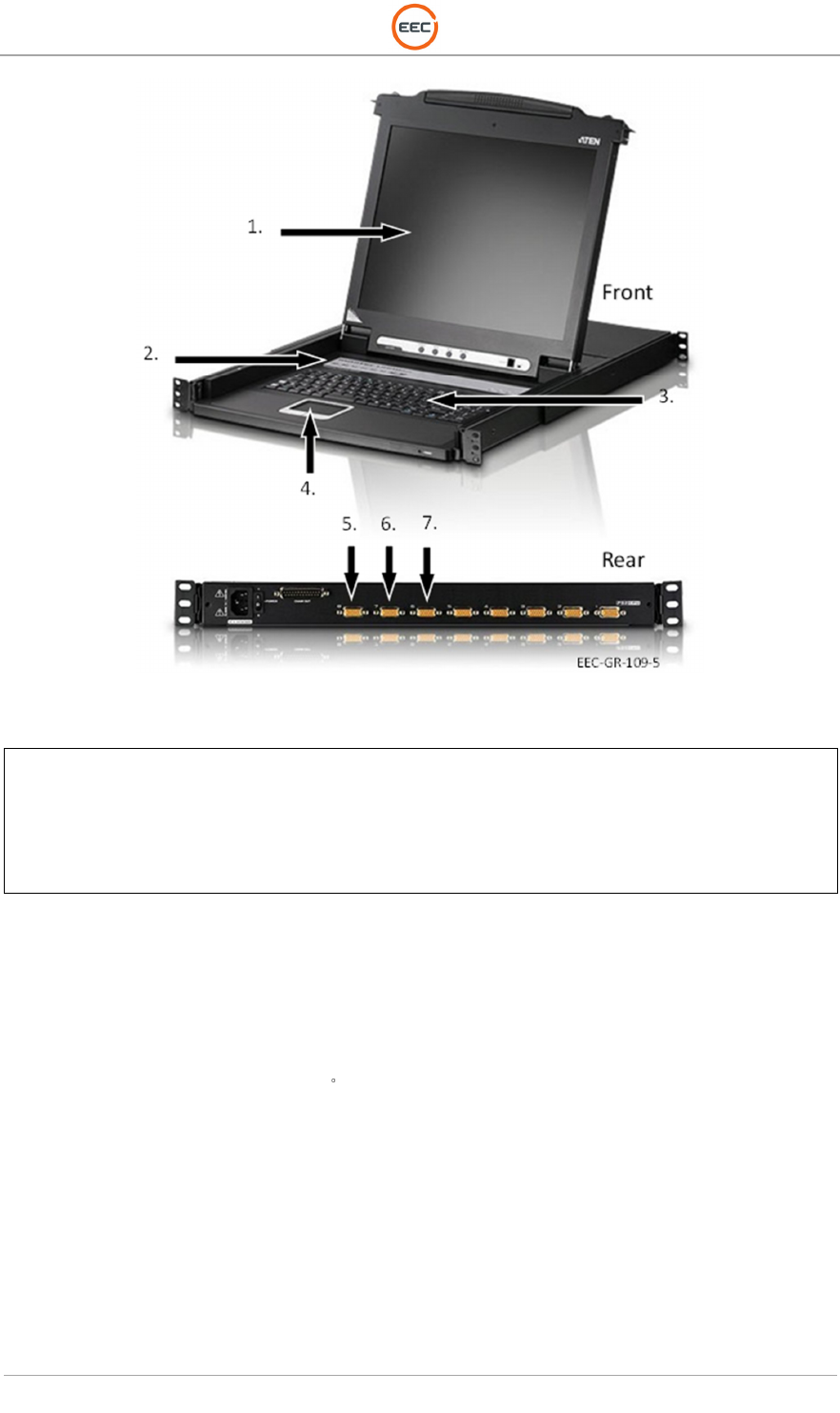
Figure 7. Keyboard, Video Monitor (132507-100)
1.
17
-
Inch Display
2. Source Selection
3. Keyboard
4. Touchpad
5. EDGE (V1)
6. RCU (V2)
7. IQ2-DSP (V3)
The keyboard has a standard laptop-style touchpad with two command buttons for manipulation
of the command cursor and executing operator commands. The display screen is a 17-in. liquid
crystal display (LCD) color monitor.
Key features of the KVM include:
• Integrated KVM console featuring a 17-in. LCD color monitor in slide-away housing
• LCD module rotates up to 115 for a more comfortable viewing angle
• 105-key keyboard
• Compatible with all operating systems (O/S) platforms PC (Windows, Linux, Unix, Mac)
• Less than 1U high mountable rack
• Auto PS/2 and universal serial bus (USB) interface detection
• Internal built-in power
• Dedicated hotkey mode and on-screen display (OSD) invocation keys
• Computer selection via pushbutton, hotkeys and OSD
• Superior video quality - up to 1280x1024
• A-Grade thin-film-transistor (TFT) LCD panel
• RoHS compliant.
T
ECHNICAL
D
OCUMENTATION
P
ROTECTING
P
EOPLE AND
A
SSETS
®
D
ATE
:
27
M
ARCH
2017
|
V
ERSION
:
1.8
16
R
ANGER
®
-
X5
R
ADAR
S
YSTEM
(M
OBILE
)
F
UNCTIONAL
O
VERVIEW AND
T
HEORY OF
O
PERATION
EEC
®
|
C
OMPANY
P
ROPRIETARY
1.1.4. EDGE Workstation (Unit 1 A4)
The EDGE Workstation (see separate EDGE Manual) is a standard computer system nearly
identical to the IQ2-DSP computer system. The EDGE software operates on the Linux platform
and shares the KVM with the IQ2-DSP and RCU systems.
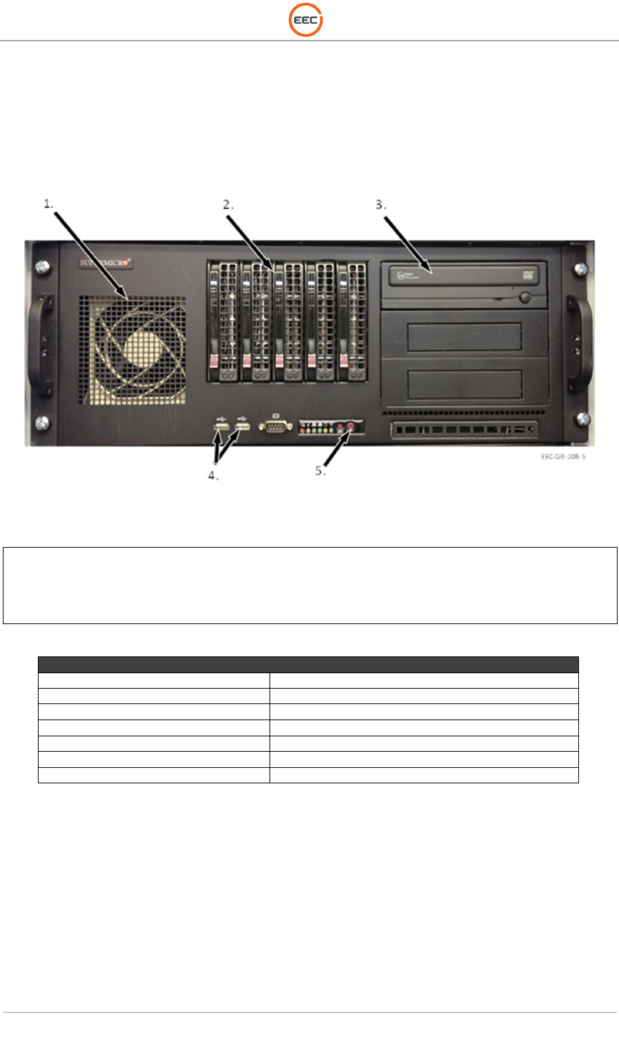
Figure 8. EDGE Workstation, Rack Mount
1.
Cooling Fan
2. Raid Drives
3. DVD Drive
4. USB Ports
5. Power Button
EDGE Computer Characteristics
Processor
Intel Xeon quad
-
core 5520 or superior
Memory:
16GB DD3
Disk:
1TB in
RAID1, including SATA RAID Card
Ethernet:
Two Gigabit Ethernet ports
Operating System:
Linux
Extra Drive Bay
16X DVD R/W
Video Card
Nvidia GTS 450 1GB or better
Table 1. EDGE Computer Characteristics
T
ECHNICAL
D
OCUMENTATION
P
ROTECTING
P
EOPLE AND
A
SSETS
®
D
ATE
:
27
M
ARCH
2017
|
V
ERSION
:
1.8
17
R
ANGER
®
-
X5
R
ADAR
S
YSTEM
(M
OBILE
)
F
UNCTIONAL
O
VERVIEW AND
T
HEORY OF
O
PERATION
EEC
®
|
C
OMPANY
P
ROPRIETARY
1.1.5. 16-Port Gigabit Ethernet Switch (Unit 1 A5)
The 16-Port Ethernet Switch provides connectivity between components in the system and the
RCU. The 16-Port Ethernet Switch has up to 48 Gbps of bandwidth and can blast 2000 Mbps
per port. Each port is equipped with 10/100/1000 automatic speed and full/half-duplex sensing
plus Auto Uplink to adjust for straight-through or crossover cables to make the right link.
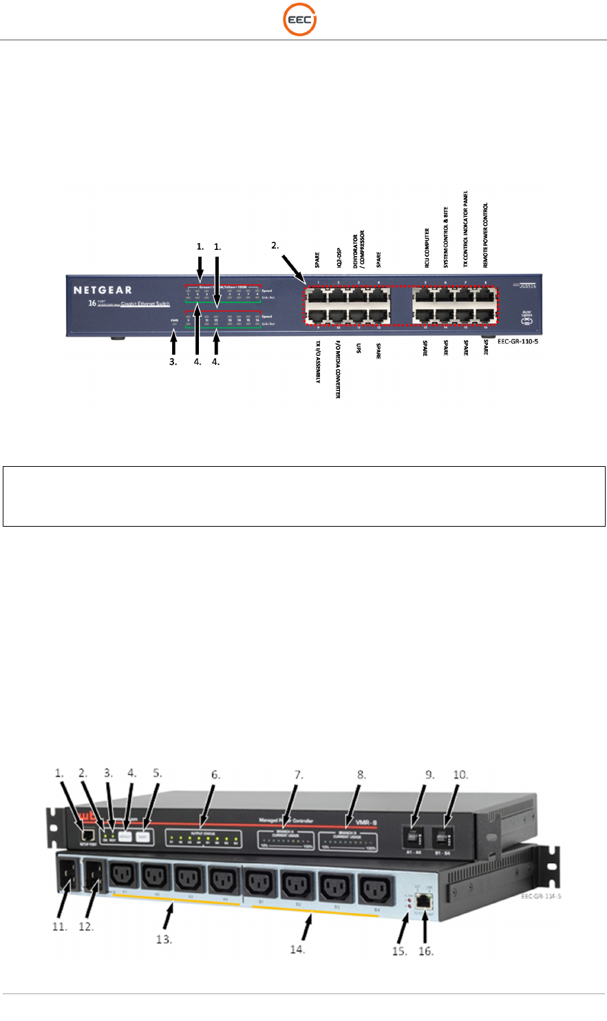
Figure 9. 16-Port Gigabit Ethernet Switch (JGS816)
1.
Speed Indicator LEDs
2. Ethernet Connections
3. Power Indicator LED
4. Link Activity LEDs
1.1.6. Power Distribution Unit (Unit 1 A6)
The Power Distribution Unit accepts the incoming 2-phase AC power from the Power Control &
Distribution Module and provides a convenient central point of distribution. The module also
contains filtering circuitry to reduce electro-magnetic interference (EMI). This module accepts
standard IEC-C13 and C19 plugs.
The Power Distribution and Control Unit provide secure, remote management of the AC powered
equipment and components in the control cabinet via Ethernet connection. The unit allows the
operator to control the power (on / off) to the various components in the radar system via Ethernet.
Figure 10. Power Distribution and Control Unit (VMR-8HD20-2)
T
ECHNICAL
D
OCUMENTATION
P
ROTECTING
P
EOPLE AND
A
SSETS
®
D
ATE
:
27
M
ARCH
2017
|
V
ERSION
:
1.8
18
R
ANGER
®
-
X5
R
ADAR
S
YSTEM
(M
OBILE
)
F
UNCTIONAL
O
VERVIEW AND
T
HEORY OF
O
PERATION
EEC
®
|
C
OMPANY
P
ROPRIETARY
1.
Setup Port
2. ON LED
3. READY LED
4. Default Button
5. Reset Button
6. Output Status Indicators
7. Branch A Current Usage
8. Branch B Current Usage
9. Branch A Circuit Breakers
10. Branch B Circuit Breakers
11. Branch A Power Inlet
12. Branch B Power Inlet
13. Branch A (A1-A4) Power Outlets
14. Branch B (B1-B4) Power Outlets
15. Alarm LEDs
16. Ethernet Connection
1.1.7. Fiber-Optic Coupler (Unit 1 A7)
The SC, 6X Fiber-Optic Coupler (see Error! Reference source not found.) is used for snap-on
mounting for fast and easy installation of as many as six fiber-optic connections between the
Control Cabinet and the Antenna/Pedestal.
1.1.8. Fiber Optic Media Converter Assembly (Unit 1 A8)
The Fiber-Optic Converter Assembly contains an Ethernet Switch for network access and to
convert fiber-optic signal from the Antenna/Pedestal to Ethernet, a 24 VDC Power Supply to
supply direct current (DC) power to the Ethernet Hub, and a Fuse Block to protect the critical
circuits on the assembly.
Figure 11. Fiber Optic Media Converter Assembly (133116-100)

T
ECHNICAL
D
OCUMENTATION
P
ROTECTING
P
EOPLE AND
A
SSETS
®
D
ATE
:
27
M
ARCH
2017
|
V
ERSION
:
1.8
19
R
ANGER
®
-
X5
R
ADAR
S
YSTEM
(M
OBILE
)
F
UNCTIONAL
O
VERVIEW AND
T
HEORY OF
O
PERATION
EEC
®
|
C
OMPANY
P
ROPRIETARY
1.
Terminal Block End Stop (CA702)
2. Fuse Block (3 Each), (CAFL4U)
3. Power Supply, 24 VDC (DPP100-24)
4. Ethernet Switch, 7-Port, 1 FO (EDS-308-M-SC-T)
1.1.8.1. 7-Port Ethernet Switch with 1-Fiber Optic Port (Unit 1 A8 A1)
The Ethernet Switch with Fiber-Optic Media Converter provides network access to the RCU
computer for the Analog and Discrete Input Modules and converts a fiber-optic connection to
Ethernet. The fiber-optic connection extends Ethernet connectivity to the Antenna/Pedestal.
1.1.8.2. 24VDC Power Supply (Unit 1 A8 PS1)
The 24 VDC power supply provides power to the 7-Port Ethernet Switch. See also paragraph
1.1.10.4.
1.1.9. UPS, 2000/1800 KVA (Unit 1 A9)
The 2KVA Uninterruptable Power Supply (UPS) provides adequate power for the Control
Cabinet. The 2KVA UPS provides backup power and line conditioning for the all components in
the Control Cabinet.
Figure 12. UPS, Powerware Model 9130, (PW9130I2000R-XL)

T
ECHNICAL
D
OCUMENTATION
P
ROTECTING
P
EOPLE AND
A
SSETS
®
D
ATE
:
27
M
ARCH
2017
|
V
ERSION
:
1.8
20
R
ANGER
®
-
X5
R
ADAR
S
YSTEM
(M
OBILE
)
F
UNCTIONAL
O
VERVIEW AND
T
HEORY OF
O
PERATION
EEC
®
|
C
OMPANY
P
ROPRIETARY
1.
On / Off Button
2. Escape Button
3. UP Button
4. DOWN Button
5. Enter Button
6. Power Indicator (Green)
7. On Batter Indicator (Yellow)
8. Bypass Indicator (Yellow)
9. Alarm Indicator (Red)
10. Power Output Segment 1
11. Remote Power Off (REPO)
12. Cooling Fan
13. RS232 Connection
14. Power Input
15. Power Output Segment 2
16. Ground Connection
17. Standard Relay Output Contact
18. Communication Bay
19. SNMP Card (Ethernet)
The UPS will power the Ranger-X5 for up to 15 minutes. External (optional) battery packs can
extend the operational time of the UPS and Ranger-X5.
1.1.10. DC Power Distribution Plate (Unit 1 A10)
A proprietary power control system and industry-standard AC/DC power supplies are installed in
the Control Cabinet. This includes a 48VDC power supply and a 24VDC power supply. DC
Power is transmitted from the Control Cabinet to the pedestal through shielded cable and the
FOSR (Fiber-Optic Slip Ring) system.
T
ECHNICAL
D
OCUMENTATION
P
ROTECTING
P
EOPLE AND
A
SSETS
®
D
ATE
:
27
M
ARCH
2017
|
V
ERSION
:
1.8
21
R
ANGER
®
-
X5
R
ADAR
S
YSTEM
(M
OBILE
)
F
UNCTIONAL
O
VERVIEW AND
T
HEORY OF
O
PERATION
EEC
®
|
C
OMPANY
P
ROPRIETARY
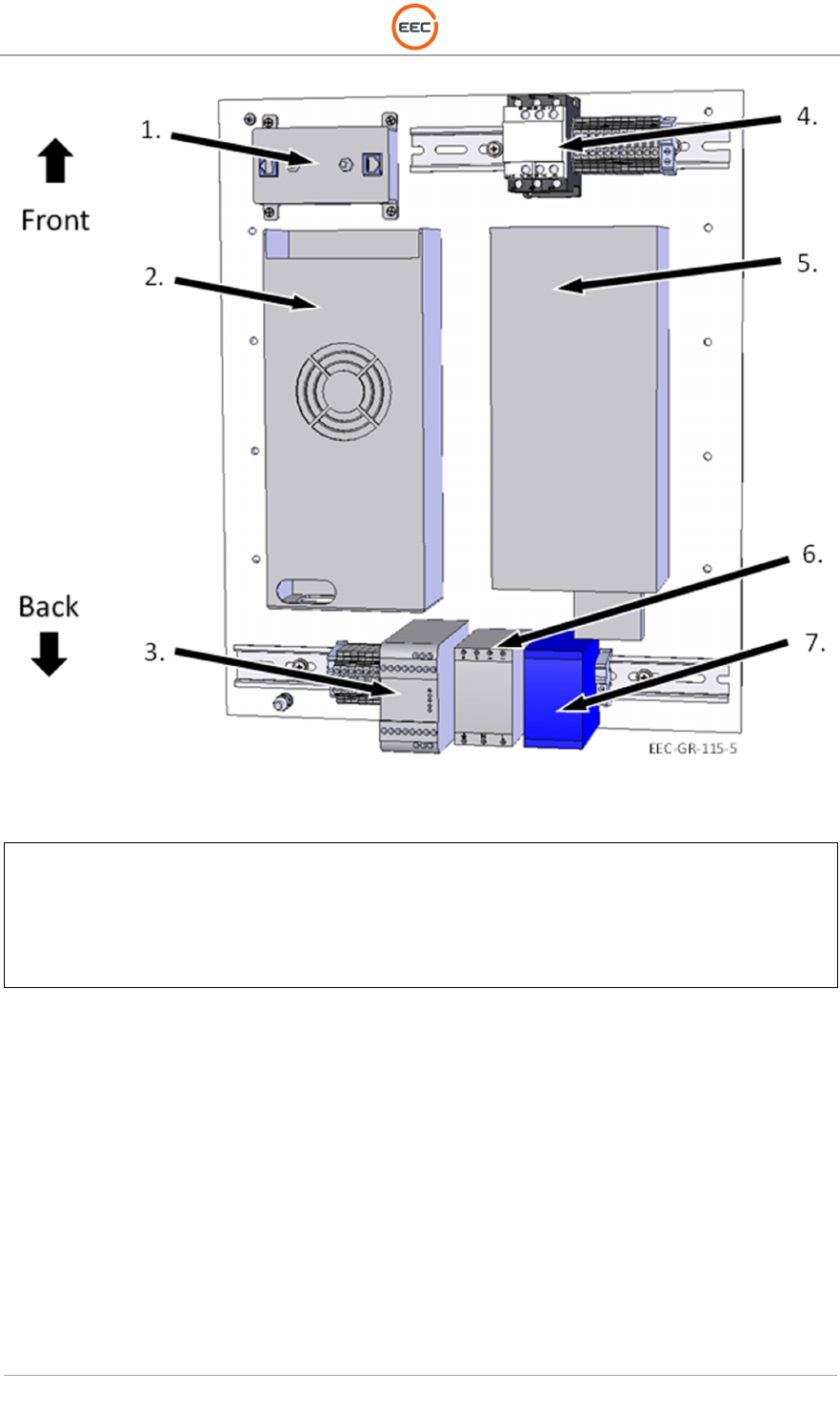
Figure 13. DC Power Distribution Plate (134932-101)
1.
Lightning Protect Module (A1)
-
HGLN
-
CAT6
-
HP
2. Power Supply, 600W, 24V (PS3) – GEM600-24G
3. Safety Relay (K2) – RT6-24VDC
4. 3-Phase Contactor, 24VDC (K1) – 226-0516
5. Power Supply, 48VDC, 32A, (PS2) – RSP1500-48
6. Power Supply, 24VDC (PS1) – DPP50-24
7. Power Supply, 12VDC (PS4) – DPP30-12
T
ECHNICAL
D
OCUMENTATION
P
ROTECTING
P
EOPLE AND
A
SSETS
®
D
ATE
:
27
M
ARCH
2017
|
V
ERSION
:
1.8
22
R
ANGER
®
-
X5
R
ADAR
S
YSTEM
(M
OBILE
)
F
UNCTIONAL
O
VERVIEW AND
T
HEORY OF
O
PERATION
EEC
®
|
C
OMPANY
P
ROPRIETARY
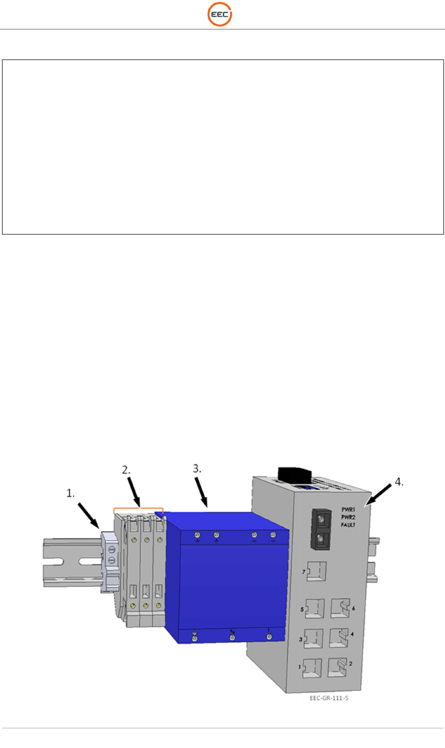
1.1.10.1. Lightning Protection Module (Unit 1 A10 A1)
(See Figure 13, Point 1)
The lighting protection module protects the main Ethernet input from outside the Ranger-X5 radar
system.
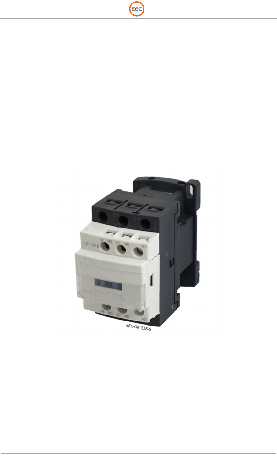
1.1.10.2. Contactor, 3-Phase, 24VDC (Unit 1 A10 K1)
(See Figure 13, Point 4 and Figure 14)
The Contactor (K1) receives DC power from the Safety Replay (K2). When DC power is not
available, the Contactor (K1) is open (Normally Open) it removes all AC power to the remaining
power supplies on the DC Power Distribution Plate. This ensures the power in the pedestal is off
and the system stops radiating and the antenna stops moving.
Figure 14. Contactor (226-0516)
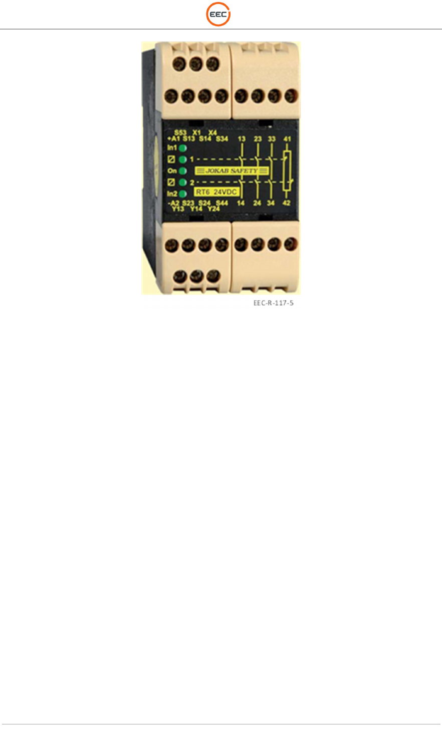
1.1.10.3. Safety Relay (Unit 1 A10 K2)
(See Figure 13, Point 3)
The Safety Relay (K2) receives DC power from the 24VDC Power Supply (PS1). The Safety
Relay receives command and control to open or close DC power output to the Contactor (K1)
from the E-Stop Control Switches on the E-Stop Panel (Unit 1 A12) and/or on the Pedestal Plate
Enclosure Assembly (Unit 2 A1 A5).
When an E-Stop Button is depressed, the Safety Relay stops sending DC power to the
Contactors (K1) and it opens. When the Contactor (K1) is open, it removes all AC power to the
remaining DC Power Supplies (PS2, PS3, and PS4).
T
ECHNICAL
D
OCUMENTATION
P
ROTECTING
P
EOPLE AND
A
SSETS
®
D
ATE
:
27
M
ARCH
2017
|
V
ERSION
:
1.8
23
R
ANGER
®
-
X5
R
ADAR
S
YSTEM
(M
OBILE
)
F
UNCTIONAL
O
VERVIEW AND
T
HEORY OF
O
PERATION
EEC
®
|
C
OMPANY
P
ROPRIETARY
Figure 15. Safety Relay (RT6-24VDC)
1.1.10.4. 24VDC Power Supply (Unit 1 A10 PS1)
(See Figure 13, Point 6)
The 24VDC Power Supply (PS1) is outside of the control of the Emergency Stop System. PS1
provides power to the Safety Replay (RT6), which in turn, controls the AC power supply to the
other DC Power Supplies (PS2, PS3, and PS4).
1.1.10.5. 48VDC Power Supply (Unit 1 A10, PS2)
(See Figure 13, Point 5)
The 48VDC Power Supply (PS2) provides all the 48VDC voltage for the Antenna / Pedestal
Assembly.
1.1.10.6. 24VDC Power Supply, 600W, 27A Peak (Unit 1 A10 PS3)
(See Figure 13, Point 2)
The 24VDC Power Supply (PS3) provides all the 24VDC voltage for the Antenna / Pedestal
Assembly.
T
ECHNICAL
D
OCUMENTATION
P
ROTECTING
P
EOPLE AND
A
SSETS
®
D
ATE
:
27
M
ARCH
2017
|
V
ERSION
:
1.8
24
R
ANGER
®
-
X5
R
ADAR
S
YSTEM
(M
OBILE
)
F
UNCTIONAL
O
VERVIEW AND
T
HEORY OF
O
PERATION
EEC
®
|
C
OMPANY
P
ROPRIETARY
1.1.10.7. 12VDC Power Supply (Unit 1 A10 PS4)
The 12VDC Power Supply (PS4) provides all the 12VDC voltage for the Antenna / Pedestal
Assembly.
(See Figure 13, Point 7)
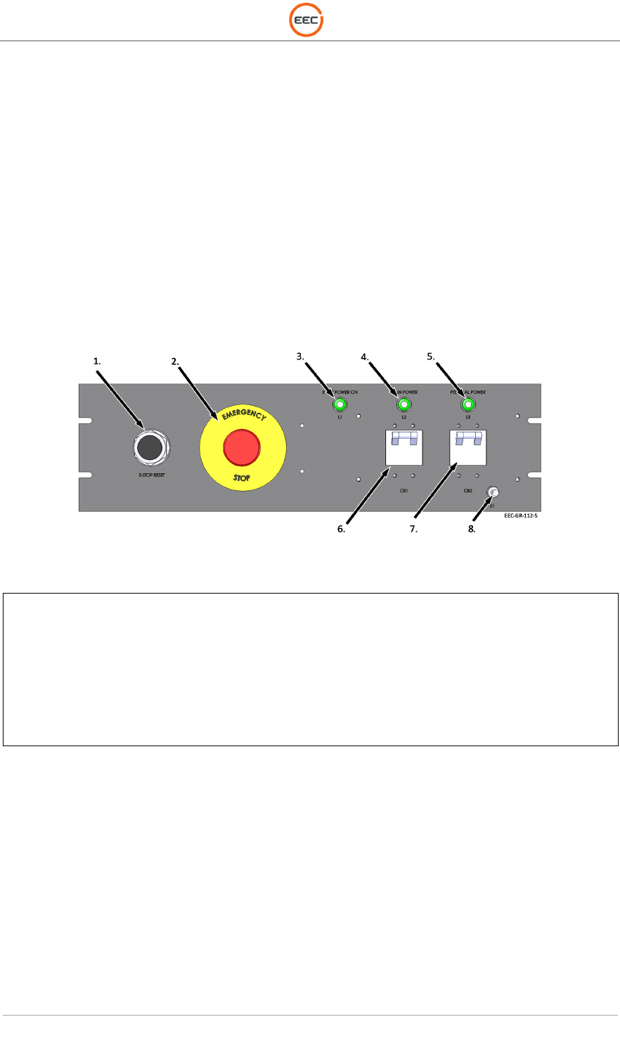
1.1.11. E-Stop Panel (Unit 1 A11)
The E-Stop Control panel contains the E-Stop Reset button, the E-Stop Button, Power Indicators,
and two Circuit Breakers. The Main Power circuit breaker (CB1) controls power to the entire
system. The Pedestal Power circuit breaker (CB2) controls the power to the DC Power
Distribution Plate (see paragraph 1.1.10).
Figure 16. Emergency Stop Panel (134933-100)
1.
E
-
Stop Reset Button (2XVT5)
2. E-Stop Button
(704-0742)
(704-9631)
(704-9104)
3. Input Power LED – L1 (679-9774)
4. Main Power LED – L2 (679-9774)
5. Pedestal Power LED – (679-9774)
6. Circuit Breaker – Main – 50A (683-0035)
7. Circuit Breaker – Pedestal – 10A (683-0037)
T
ECHNICAL
D
OCUMENTATION
P
ROTECTING
P
EOPLE AND
A
SSETS
®
D
ATE
:
27
M
ARCH
2017
|
V
ERSION
:
1.8
25
R
ANGER
®
-
X5
R
ADAR
S
YSTEM
(M
OBILE
)
F
UNCTIONAL
O
VERVIEW AND
T
HEORY OF
O
PERATION
EEC
®
|
C
OMPANY
P
ROPRIETARY
1.1.12. I/O Panel Assembly (Unit 1 A12)
The Indoor Control Cabinet is equipped with an I/O Panel Assembly to connect the Control
Cabinet to the Pedestal Unit. The AC Input for the Outdoor Control Cabinet is through a standard,
commercial grade circuit breaker box.
Figure 17. I/O Panel Assembly, 19-inch Rack (134938-100)
1.
AC Power IN (not used)
2. Fiber Optic Cable Gland
3. Pedestal Communication Interconnect
4. Ground Connection Point
5. Pedestal Power Interconnect
6. Ethernet Connection

T
ECHNICAL
D
OCUMENTATION
P
ROTECTING
P
EOPLE AND
A
SSETS
®
D
ATE
:
27
M
ARCH
2017
|
V
ERSION
:
1.8
26
R
ANGER
®
-
X5
R
ADAR
S
YSTEM
(M
OBILE
)
F
UNCTIONAL
O
VERVIEW AND
T
HEORY OF
O
PERATION
EEC
®
|
C
OMPANY
P
ROPRIETARY
This page intentionally blank