Enterprise Electronics RANGERX5 Ranger-X5 RADAR User Manual Overview Theory Part 2
Enterprise Electronics Corporation Ranger-X5 RADAR Overview Theory Part 2
Contents
User Manual Overview Theory Part 2

T
ECHNICAL
D
OCUMENTATION
P
ROTECTING
P
EOPLE AND
A
SSETS
®
D
ATE
:
27
M
ARCH
2017
|
V
ERSION
:
1.8
27
R
ANGER
®
-
X5
R
ADAR
S
YSTEM
(M
OBILE
)
F
UNCTIONAL
O
VERVIEW AND
T
HEORY OF
O
PERATION
EEC
®
|
C
OMPANY
P
ROPRIETARY
C
HAPTER
2
A
NTENNA
/
P
EDESTAL
(U
NIT
2)

T
ECHNICAL
D
OCUMENTATION
P
ROTECTING
P
EOPLE AND
A
SSETS
®
D
ATE
:
27
M
ARCH
2017
|
V
ERSION
:
1.8
28
R
ANGER
®
-
X5
R
ADAR
S
YSTEM
(M
OBILE
)
F
UNCTIONAL
O
VERVIEW AND
T
HEORY OF
O
PERATION
EEC
®
|
C
OMPANY
P
ROPRIETARY
This page intentionally blank.

T
ECHNICAL
D
OCUMENTATION
P
ROTECTING
P
EOPLE AND
A
SSETS
®
D
ATE
:
27
M
ARCH
2017
|
V
ERSION
:
1.8
29
R
ANGER
®
-
X5
R
ADAR
S
YSTEM
(M
OBILE
)
F
UNCTIONAL
O
VERVIEW AND
T
HEORY OF
O
PERATION
EEC
®
|
C
OMPANY
P
ROPRIETARY
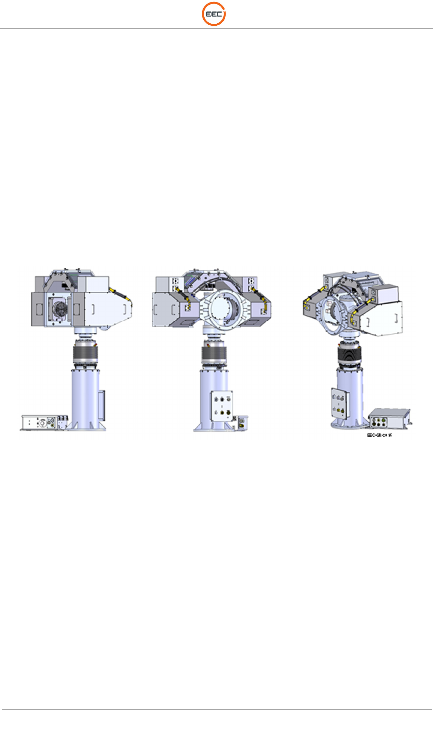
2. Antenna / Pedestal (Unit 2)
Figure 18 shows the short pedestal with a 1.8 meter reflector. Consult the Schematics and
Drawings that come with your system for detailed information.
Figure 18. Antenna / Pedestal Unit – 1.8 Meter Reflector (135955-101)
T
ECHNICAL
D
OCUMENTATION
P
ROTECTING
P
EOPLE AND
A
SSETS
®
D
ATE
:
27
M
ARCH
2017
|
V
ERSION
:
1.8
30
R
ANGER
®
-
X5
R
ADAR
S
YSTEM
(M
OBILE
)
F
UNCTIONAL
O
VERVIEW AND
T
HEORY OF
O
PERATION
EEC
®
|
C
OMPANY
P
ROPRIETARY
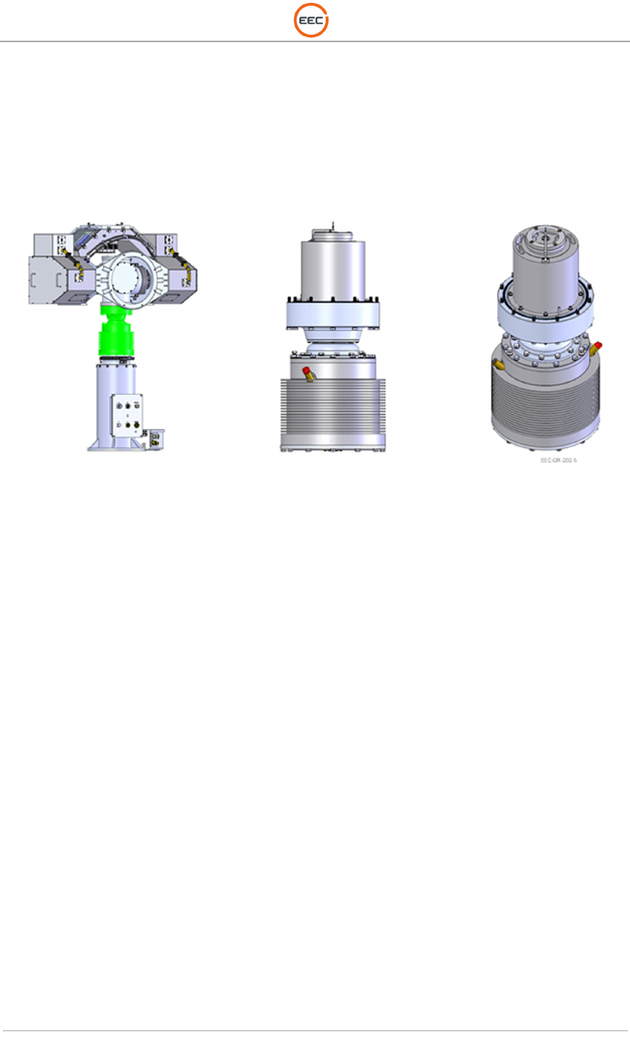
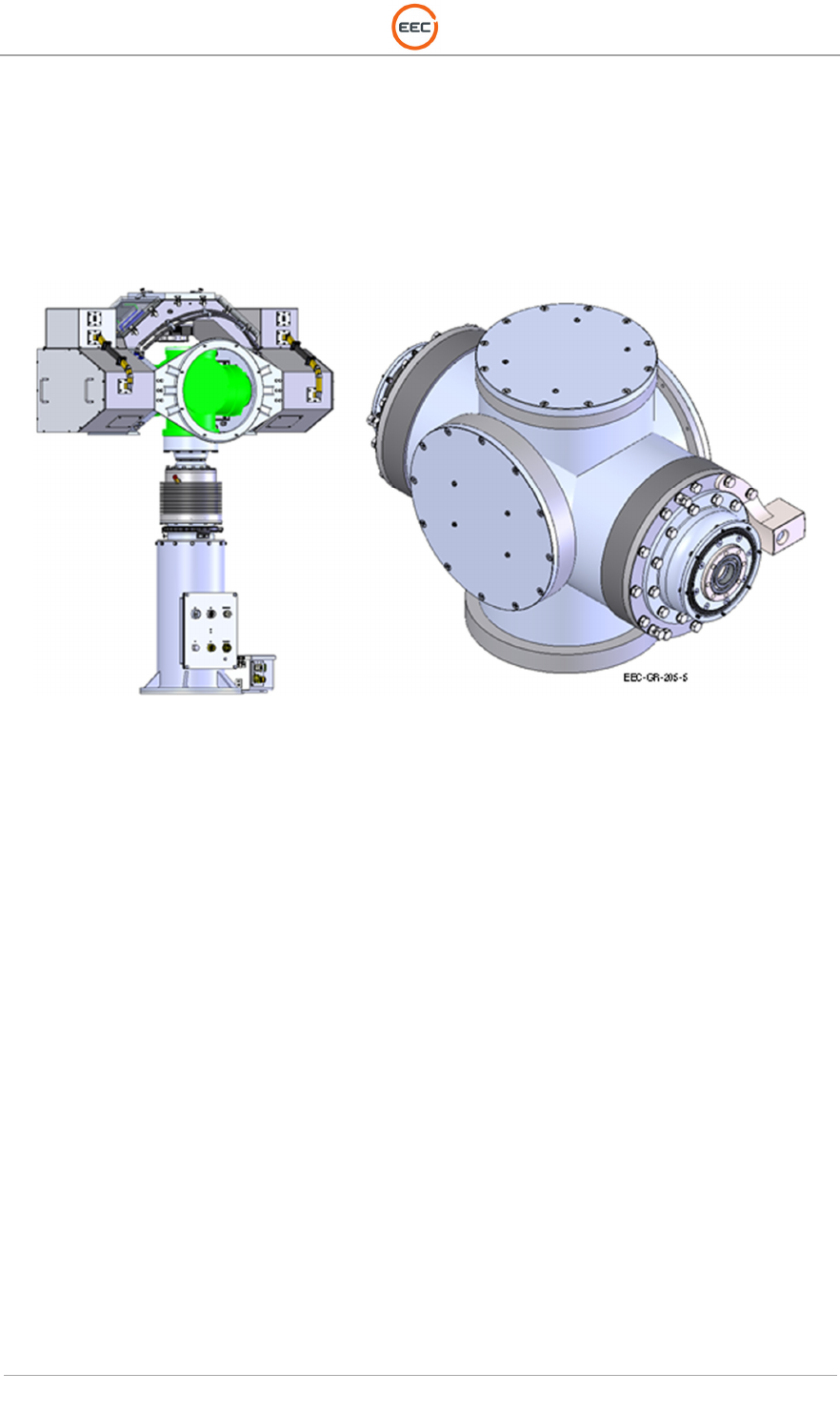
2.1. Pedestal Assembly (Unit 2 A1)
The design of the pedestal system for the Ranger-X5 utilizes components and elements that
allow for constant outdoor exposure and 24/7 unattended operation. Utilizing multiple O-ring
seals and weather tight compartments prevents contaminants from entering the pedestal from
the outside environment. The motor drives used in both azimuth and elevation utilize a wave
generator and circular spine, eliminating traditional gearing found in most pedestal systems.
There is no traditional bull-gear and pinion, as the motor drive itself is the rotation axis.
Since the motor drives are sealed and permanently lubricated, there is no periodic maintenance
required. Additionally, this technology also eliminates backlash and the need to adjust backlash,
and provides exceptionally high positional accuracy and repeatability. The remaining bearings
utilized (elevation idler side, and drive tube stabilizer) in the Ranger-X5 are also permanently
sealed and require no maintenance.
A sealed slip ring limits the need for periodic or preventative maintenance. The slip ring is design
is originally for high-speed operation and has a proven pedigree in military and aviation
applications. Even at the highest rotation speed of the Ranger-X5 for weather operation, the slip
ring operates at less than 25% of its rotational speed capacity.
Figure 19. Pedestal Unit (135885-100)
T
ECHNICAL
D
OCUMENTATION
P
ROTECTING
P
EOPLE AND
A
SSETS
®
D
ATE
:
27
M
ARCH
2017
|
V
ERSION
:
1.8
31
R
ANGER
®
-
X5
R
ADAR
S
YSTEM
(M
OBILE
)
F
UNCTIONAL
O
VERVIEW AND
T
HEORY OF
O
PERATION
EEC
®
|
C
OMPANY
P
ROPRIETARY
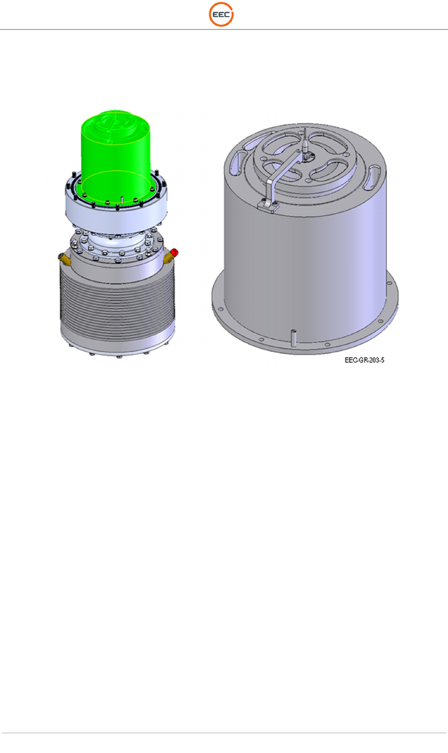
2.1.1. Azimuth Assembly (Unit 2 A1 A1)
The Azimuth Assembly is a sealed unit. There are no “field serviceable” components in the
Azimuth unit. The sealed Slip Ring Assembly extends into the Elevation Assembly and the top
of the Fiber Optic Rotary Joint is accessible from the maintenance port on the Elevation
Assembly. The mechanical components are virtually “maintenance free,” with the Actuator Unit
boasting an MTBF (Mean Time Between Failure) of more than 180,000 operational hours (> 20
years).
Figure 20. Azimuth Assembly (135887-100)
T
ECHNICAL
D
OCUMENTATION
P
ROTECTING
P
EOPLE AND
A
SSETS
®
D
ATE
:
27
M
ARCH
2017
|
V
ERSION
:
1.8
32
R
ANGER
®
-
X5
R
ADAR
S
YSTEM
(M
OBILE
)
F
UNCTIONAL
O
VERVIEW AND
T
HEORY OF
O
PERATION
EEC
®
|
C
OMPANY
P
ROPRIETARY
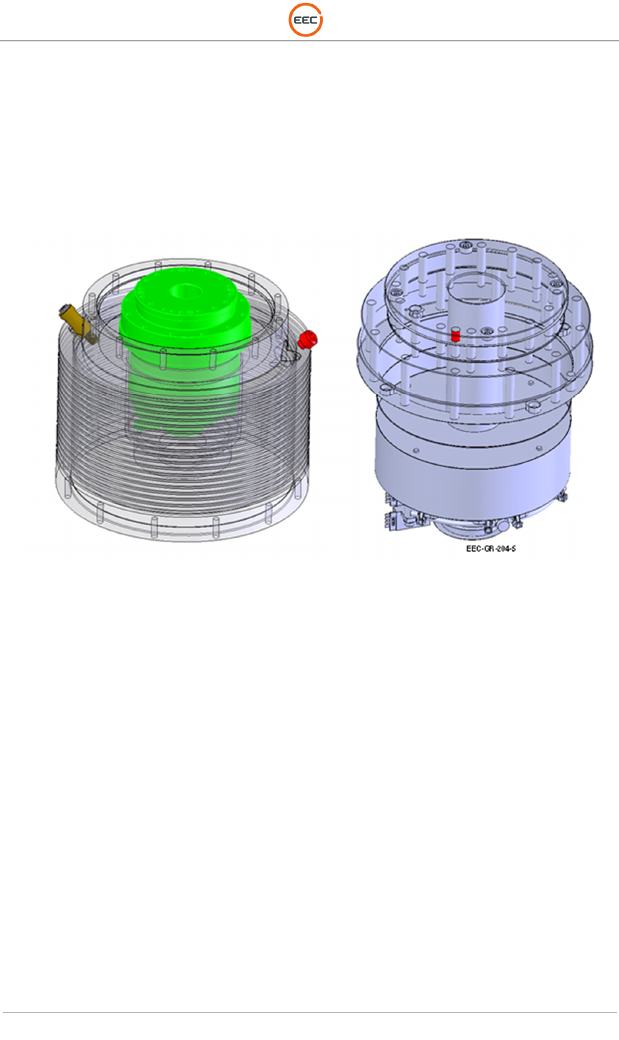
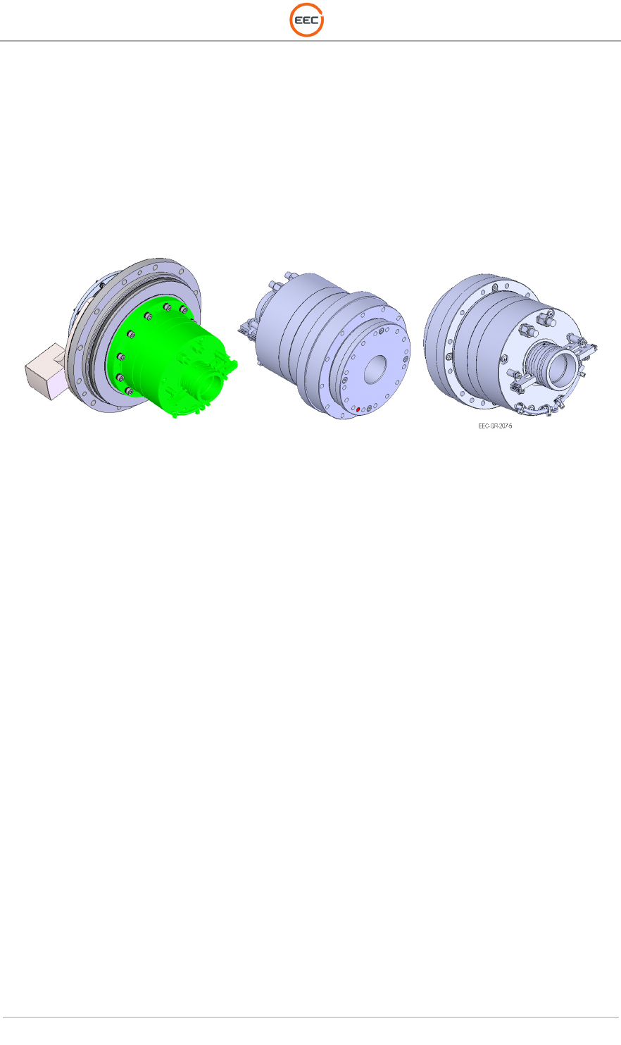
2.1.1.1. Slip Ring with Fiber Optic Rotary Joint (Unit 2 A1 A1 A1)
The Fiber Optic Rotary Joint / Slip Ring Assembly is permanently installed in the Azimuth
Assembly. It is completely sealed and requires no maintenance.
Figure 21. Slip Ring Assembly (134523-100)
T
ECHNICAL
D
OCUMENTATION
P
ROTECTING
P
EOPLE AND
A
SSETS
®
D
ATE
:
27
M
ARCH
2017
|
V
ERSION
:
1.8
33
R
ANGER
®
-
X5
R
ADAR
S
YSTEM
(M
OBILE
)
F
UNCTIONAL
O
VERVIEW AND
T
HEORY OF
O
PERATION
EEC
®
|
C
OMPANY
P
ROPRIETARY
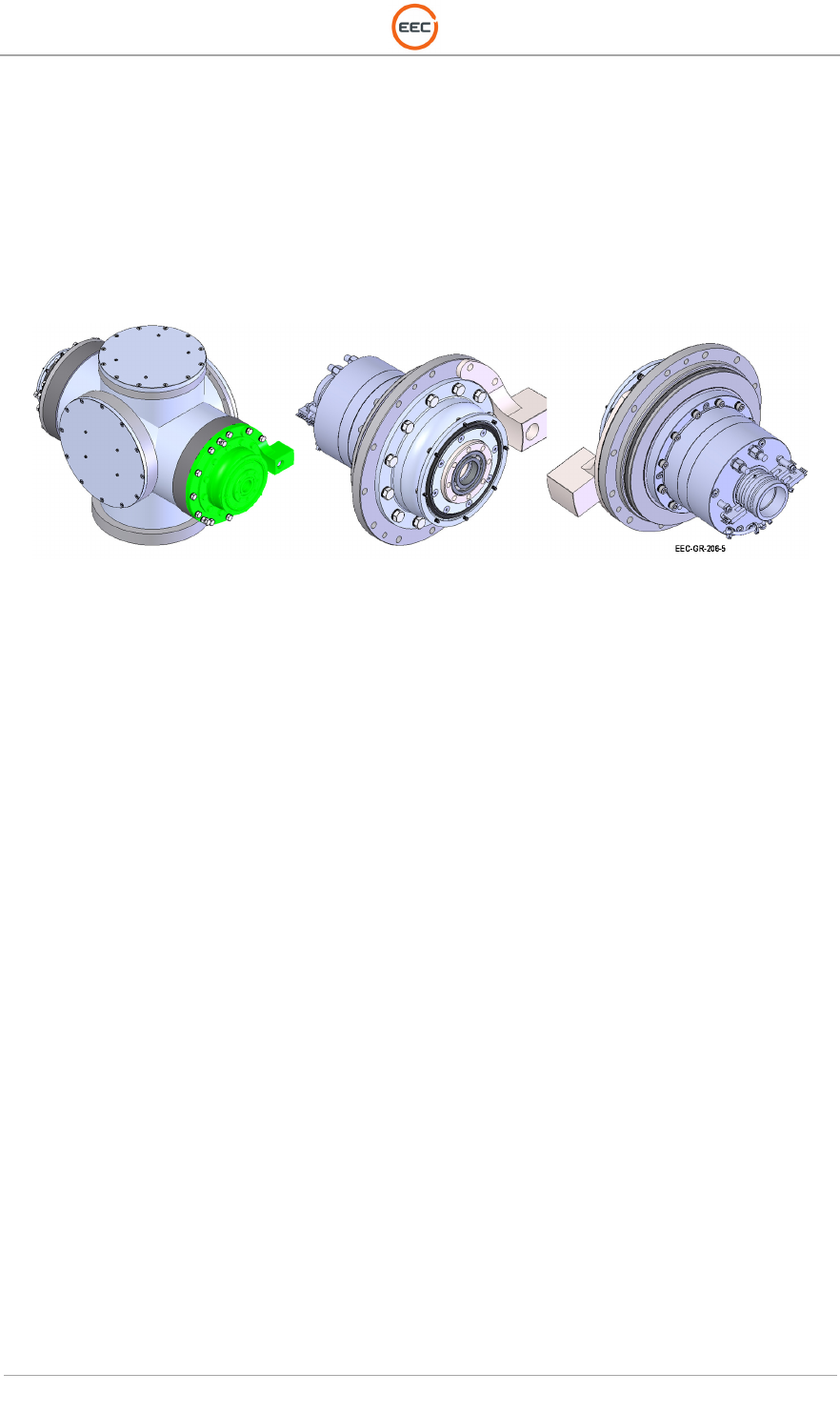
2.1.1.2. Actuator Unit (Unit 2 A1 A1 A2)
The Actuator Unit is the main drive of the Azimuth Section. The unit connects to the receives
command and control function from the Servo Amplifier (Unit 2 A1 A5 A2) and Aquarian Controller
(Unit 2 A1 A5 A4) located in the Pedestal Plate Enclosure Assembly (Unit 2 A1 A5).
The Actuator Unit is a sealed unit. The Mean Time Between Failure (MTBF) is more than 180,000
hours. It requires no maintenance.
Figure 22. Actuator Unit (135782-100)
T
ECHNICAL
D
OCUMENTATION
P
ROTECTING
P
EOPLE AND
A
SSETS
®
D
ATE
:
27
M
ARCH
2017
|
V
ERSION
:
1.8
34
R
ANGER
®
-
X5
R
ADAR
S
YSTEM
(M
OBILE
)
F
UNCTIONAL
O
VERVIEW AND
T
HEORY OF
O
PERATION
EEC
®
|
C
OMPANY
P
ROPRIETARY
2.1.2. Elevation Assembly (Unit 2 A1 A2)
The Elevation Assembly is an open unit. There are two access panels; both allow access to the
Servo Control System and inspection of the Actuator Assembly. The drive components of the
Elevation Assembly are virtually “maintenance free,” with the Actuator Unit boasting an MTBF
(Mean Time Between Failure) of more than 180,000 operational hours (> 20 years).
Figure 23. Elevation Assembly (135952-100)
T
ECHNICAL
D
OCUMENTATION
P
ROTECTING
P
EOPLE AND
A
SSETS
®
D
ATE
:
27
M
ARCH
2017
|
V
ERSION
:
1.8
35
R
ANGER
®
-
X5
R
ADAR
S
YSTEM
(M
OBILE
)
F
UNCTIONAL
O
VERVIEW AND
T
HEORY OF
O
PERATION
EEC
®
|
C
OMPANY
P
ROPRIETARY
2.1.2.1. Elevation Endcap Assembly (Unit 2 A1 A2 A1)
The Elevation Endcap Assembly is the pass-through point for power and communication from
the Riser to the Payload Support Assembly. There is a no-maintenance bearing to support the
movement of the payload in the elevation axis.
Figure 24. Elevation Driven Side Assembly (135539-100)
T
ECHNICAL
D
OCUMENTATION
P
ROTECTING
P
EOPLE AND
A
SSETS
®
D
ATE
:
27
M
ARCH
2017
|
V
ERSION
:
1.8
36
R
ANGER
®
-
X5
R
ADAR
S
YSTEM
(M
OBILE
)
F
UNCTIONAL
O
VERVIEW AND
T
HEORY OF
O
PERATION
EEC
®
|
C
OMPANY
P
ROPRIETARY
2.1.2.2. Actuator Unit (Unit 2 A1 A2 A1 A1)
The Actuator Unit is the main drive of the Elevation Section. The unit connects to the receives
command and control function from the Servo Amplifier (Unit 2 A1 A2 A3) and Aquarian Controller
(Unit 2 A1 A2 A4) located in the Elevation Assembly (Unit 2 A1 A2).
The Actuator Unit is a sealed unit. The Mean Time Between Failure (MTBF) is more than 180,000
hours. It requires no maintenance.
Figure 25. Actuator Unit (135782-100)
T
ECHNICAL
D
OCUMENTATION
P
ROTECTING
P
EOPLE AND
A
SSETS
®
D
ATE
:
27
M
ARCH
2017
|
V
ERSION
:
1.8
37
R
ANGER
®
-
X5
R
ADAR
S
YSTEM
(M
OBILE
)
F
UNCTIONAL
O
VERVIEW AND
T
HEORY OF
O
PERATION
EEC
®
|
C
OMPANY
P
ROPRIETARY
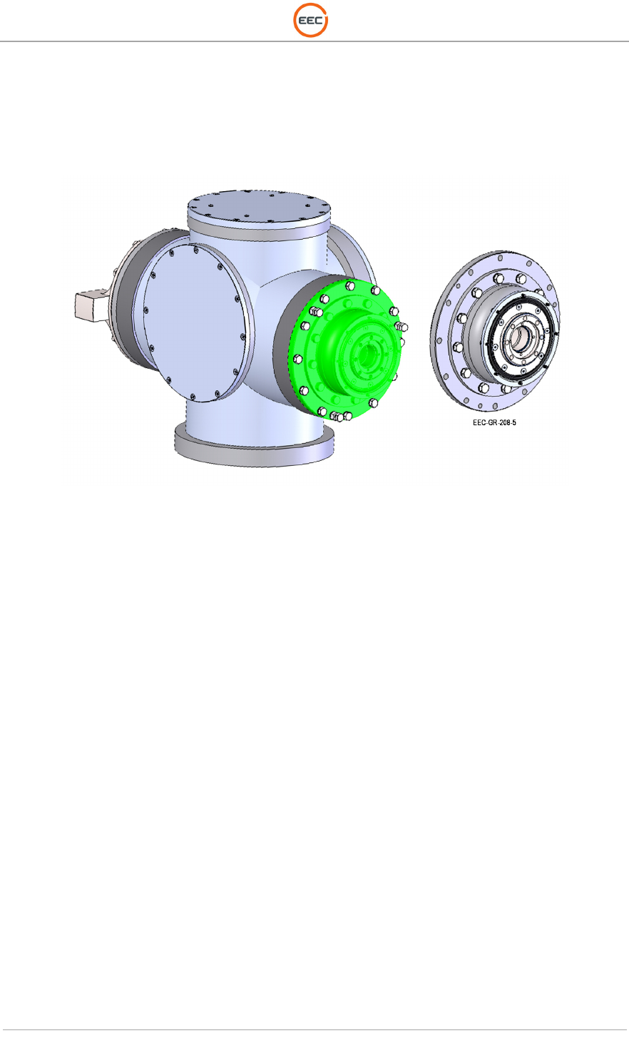
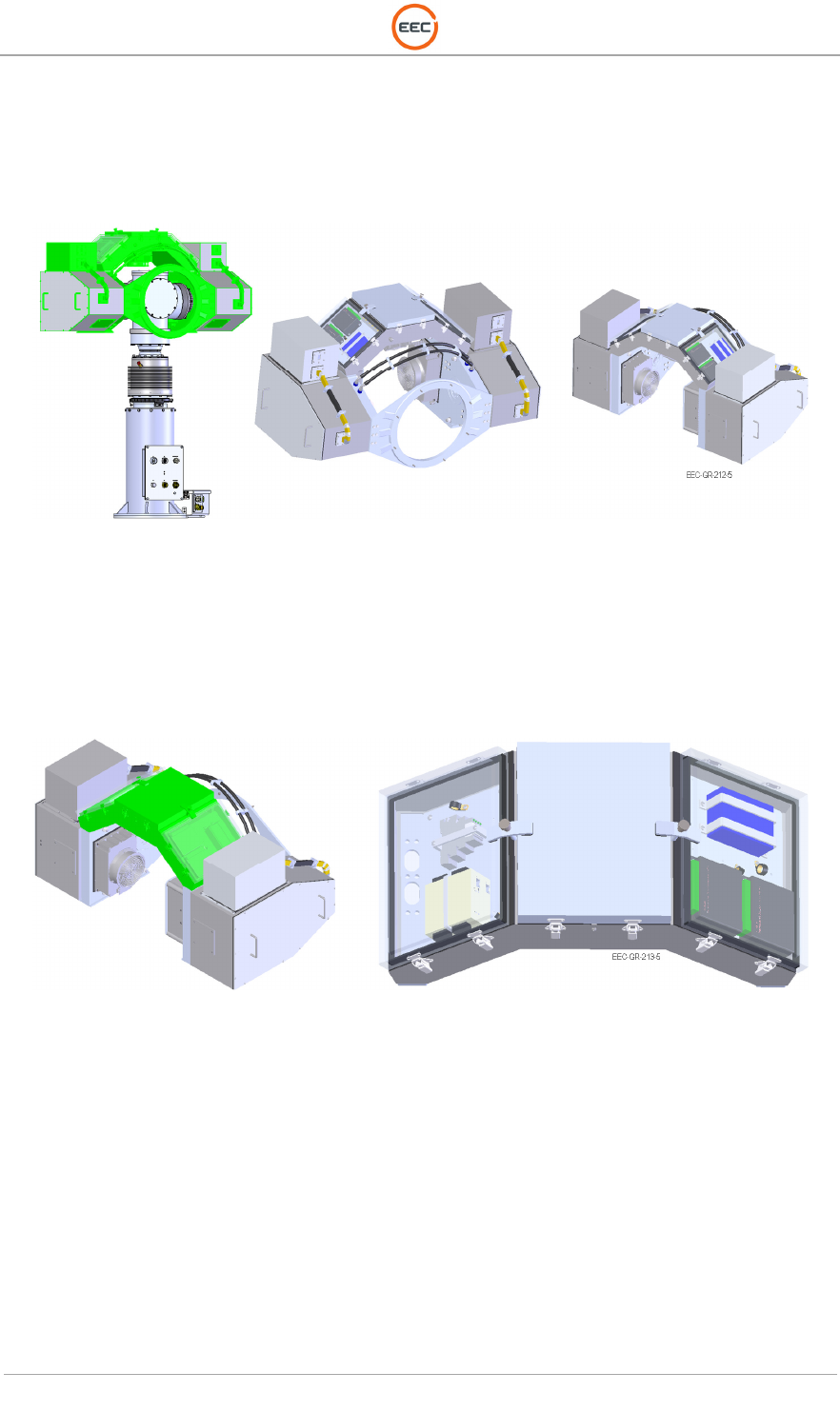
2.1.3. Elevation Driven Side Assembly (Unit 2 A1 A2 A2)
The Elevation Driven Side Assembly contains the “drive” components for the Ranger Elevation
section. This includes the Actuator Unit (see Paragraph 0).
Figure 26. Elevation Endcap Assembly (134775-100)
T
ECHNICAL
D
OCUMENTATION
P
ROTECTING
P
EOPLE AND
A
SSETS
®
D
ATE
:
27
M
ARCH
2017
|
V
ERSION
:
1.8
38
R
ANGER
®
-
X5
R
ADAR
S
YSTEM
(M
OBILE
)
F
UNCTIONAL
O
VERVIEW AND
T
HEORY OF
O
PERATION
EEC
®
|
C
OMPANY
P
ROPRIETARY
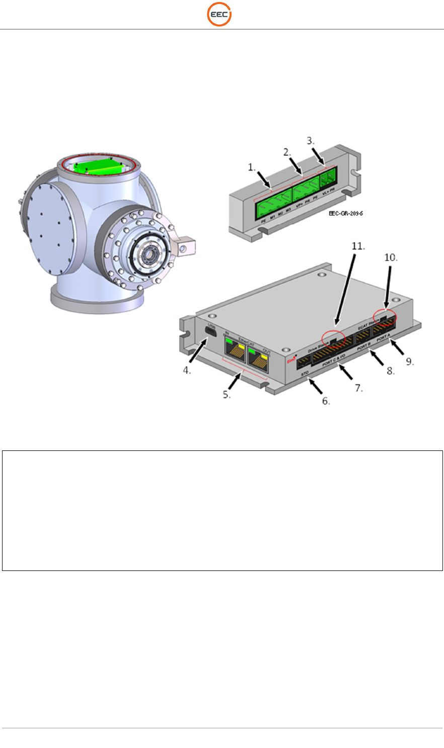
2.1.3.1. Servo Amplifier, 100V, 10A (Unit 2 A1 A2 A3)
The Servo Amplifier drives the Actuator Unit. It is an Ethernet configurable device that takes
digital and analog input/output commands sent by the Aquarian Servo Controller and converts
them to the language spoken by the actuator system and simultaneously controls the voltages
necessary to move the unit.
Figure 27. Servo Amplifier (135534-100)
1.
Power to Servo Motor (J14)
2. Main Power IN (J13)
3. Auxiliary Power IN (J12)
4. USB Connector (J9)
5. EtherCAT IN (J7) and EtherCAT OUT (J8)
6. Safe Torque Off (J11)
7. Port C and I/O (Programmable Port) (J2)
8. Port A (Encoder Connector) (J1)
9. Port B (Sine / Cosine Encoder) (J3)
10. ECAT Status Indicator
11. Drive Status Indicator
T
ECHNICAL
D
OCUMENTATION
P
ROTECTING
P
EOPLE AND
A
SSETS
®
D
ATE
:
27
M
ARCH
2017
|
V
ERSION
:
1.8
39
R
ANGER
®
-
X5
R
ADAR
S
YSTEM
(M
OBILE
)
F
UNCTIONAL
O
VERVIEW AND
T
HEORY OF
O
PERATION
EEC
®
|
C
OMPANY
P
ROPRIETARY
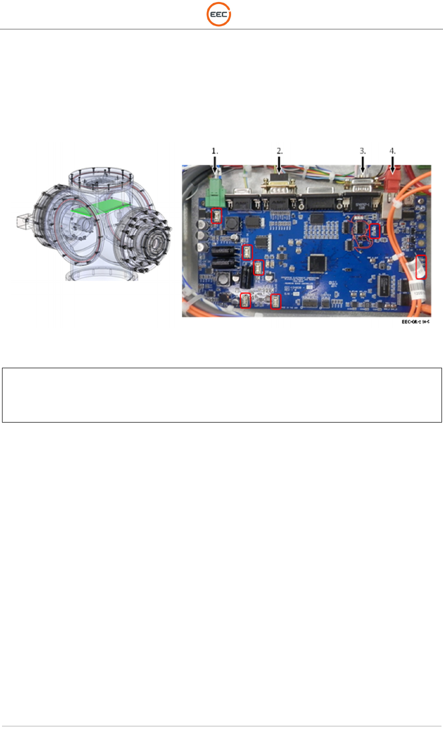
2.1.3.2. Aquarian Servo Controller PCA (Unit 2 A1 A2 A4)
The Aquarian Servo Controller is a single axis Ethernet motion controller. The Aquarian Servo
Controller provides a structured text-programming environment and the ability to perform many
modes of motion including camming, gearing, and contouring. Point-to-point control and
communications takes place over standard Ethernet connections. The Ethernet function allows
multiple handles or devices to communicate with the controller.
Figure 28. Aquarian Servo Controller (134839-103)
1.
Power Cable (P1)
2. Encoder Input from Servo Amplifier (J7)
3. Control, Status (J6)
4. Ethernet (J3)
Red Outline – Status Indicators
T
ECHNICAL
D
OCUMENTATION
P
ROTECTING
P
EOPLE AND
A
SSETS
®
D
ATE
:
27
M
ARCH
2017
|
V
ERSION
:
1.8
40
R
ANGER
®
-
X5
R
ADAR
S
YSTEM
(M
OBILE
)
F
UNCTIONAL
O
VERVIEW AND
T
HEORY OF
O
PERATION
EEC
®
|
C
OMPANY
P
ROPRIETARY
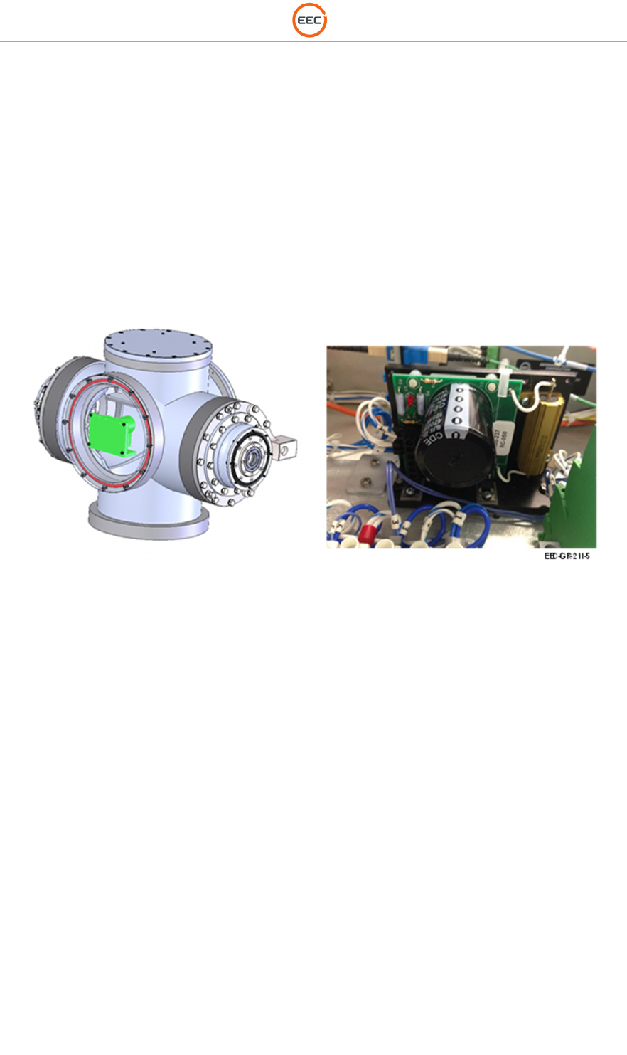
2.1.3.3. Regeneration Clamp (Unit 2 A1 A2 A5)
As with most servo systems, a clamp circuit is required to limit increase power supply buss
voltage when the motor is decelerating under load. This common name for this process is
“regeneration” and happens when the load on the unit drives the DC motor. During regeneration,
the DC motor can produce enough voltage to exceed the “input” power supply voltage. More
sophisticated servo amplifiers deal with this by channeling the increased motor voltage back to
the source power supply. If the voltage is not “clamped” to a safe level, it can destroy or severely
damage the amplifier.
The servo amplifier and controller are the types that channel the increasing voltage back to the
input power supply. A simple capacitor isn’t large enough to handle the power that generates
back into the controller when the system is under inertial load. The Regeneration Clamp is us
sufficient capacity to track the input power and ensure the servo amplifier voltage will not exceed
the capacity rating.
Figure 29. Regeneration Clamp (1000-327)
T
ECHNICAL
D
OCUMENTATION
P
ROTECTING
P
EOPLE AND
A
SSETS
®
D
ATE
:
27
M
ARCH
2017
|
V
ERSION
:
1.8
41
R
ANGER
®
-
X5
R
ADAR
S
YSTEM
(M
OBILE
)
F
UNCTIONAL
O
VERVIEW AND
T
HEORY OF
O
PERATION
EEC
®
|
C
OMPANY
P
ROPRIETARY
2.1.4. Payload Support Assembly (Unit 2 A1 A3)
The Payload Support Assembly (Unit 2 A1 A3) houses the entire transmitter and receiver system
in the Plenum Assembly (Unit 2 A1 A3 A1), the Transceiver Assemblies – Horizontal (Unit 2 A1
A3 A2) and Vertical (Unit 2 A1 A3 A3), and the Fluid Pump Assembly (Unit 2 A1 A3 A4).
Figure 30. Payload Support Assembly (135953-100)
2.1.4.1. Plenum Assembly (Unit 2 A1 A3 A1)
The Plenum Assembly (aka the Saddle) houses the IQ2 IFD, the I/O Control Modules, the Cold
Plate, the 8-Port Ethernet Switch, and the Peltier Temperature Controllers for the Cold Plate and
the Fluid Pump Assembly.
Figure 31. Plenum Assembly (135540-100)
2.1.4.1.1. IQ2 Intermediate Frequency Digitizer Assembly (Unit 2 A1 A3 A1 A1)
The IQ2-IFD receives the horizontal and vertical receive IF from the Horizontal UDC (Unit 2 A1
A3 A2 A2) and Vertical UDC (Unit 2 A1 A3 A3 A2). The IQ2-IFD digitizes the received IF and
outputs “I and Q” serial data in digital format. The data output connects to the IQ2-DSP via a
fiber-optic cable and the fiber-optic rotary joint.
The IQ2-IFD Assembly (see Error! Reference source not found.) extracts the maximum
amount of useable information from reflected radar energy. There are five 60 MHz IF channels
sampled at >76 MHz. Four of the IQ2-IFD 60 MHz IF channels (two channels for the horizontally
polarized signal and two channels for the vertically polarized signal in dual polarization systems)
include wide-band down-converters to base-band for Receiver use. The fifth IF channel normally
functions as a Transmitter sample (IF burst) channel for Transmitter amplitude and phase
correction on a pulse-by-pulse basis.
T
ECHNICAL
D
OCUMENTATION
P
ROTECTING
P
EOPLE AND
A
SSETS
®
D
ATE
:
27
M
ARCH
2017
|
V
ERSION
:
1.8
42
R
ANGER
®
-
X5
R
ADAR
S
YSTEM
(M
OBILE
)
F
UNCTIONAL
O
VERVIEW AND
T
HEORY OF
O
PERATION
EEC
®
|
C
OMPANY
P
ROPRIETARY
This processing can include pulse compression as an option. The digital IF signals pass to the
IQ2-DSP unit via a 2.5 Gbits/sec optical link and command/control/status information is through
a Gigabit Ethernet link. The unit has nine fully programmable triggers, serial angle input ports,
and other I/O ports that for special applications.
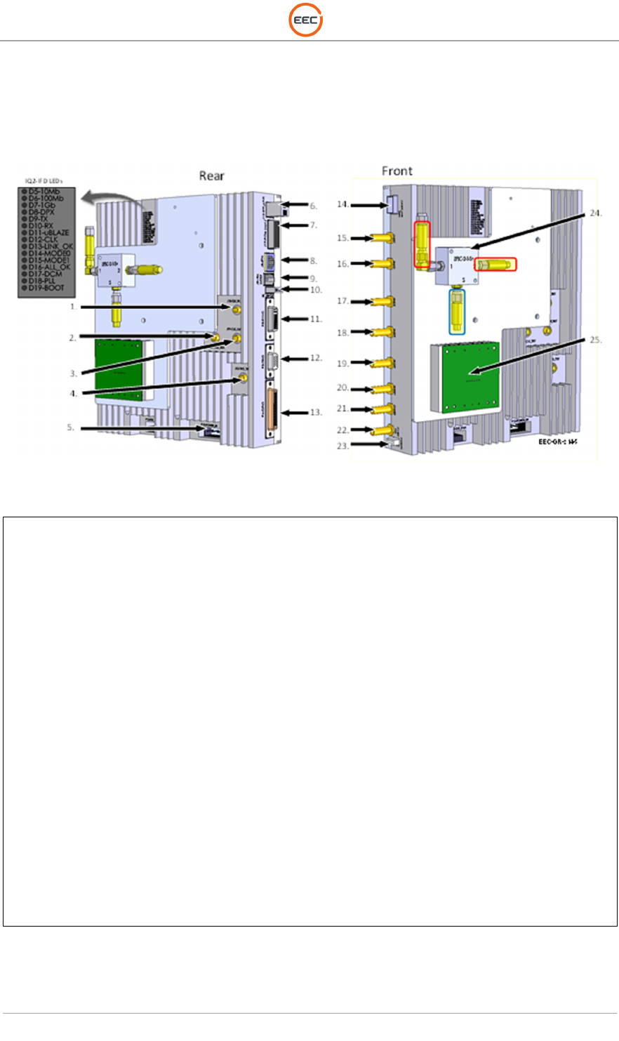
Figure 32. IQ2-IFD (134066-101)
1.
J18
–
External Clock M
onitor
2. J19 – Reference Clock Test Point
3. J10 – Reference Clock Monitor
4. J15 – Trigger Generator Test Point
5. P10 – 12 VDC Power
6. J13, Fiber Optic
7. J17 – PCIe (not used in SDP system)
8. J8 – Ethernet
9. J9 – IRX Connector (not used)
10. J12 – Antenna Position
11. P5 – Sync
12. P3 – Trigger
13. P4 – GPIO
14. J14 Fiber Optic
15. J1 – RX Channel 1
16. J2 – RX Channel 2
17. J3 – RX Channel 3
18. J4 – RX Chanel 4
19. J5 – Burst
20. J6 – Waveform Generator
21. J77 – Waveform Generator (2)
22. J11 – Clock Reference In
23. J16 – RS232 / I2C / SAFC
24. Directional Coupler, ZFDC-20-4-S+
25. IQ2 PSU PCA – 134862-100
RED OUTLINE - 10dB Attenuator, VAT-10
BLUE OUTLINE - 5dB Attenuator, VAT-5