Enterprise Electronics RANGERX5 Ranger-X5 RADAR User Manual Overview Theory Part 3
Enterprise Electronics Corporation Ranger-X5 RADAR Overview Theory Part 3
Contents
User Manual Overview Theory Part 3
T
ECHNICAL
D
OCUMENTATION
P
ROTECTING
P
EOPLE AND
A
SSETS
®
D
ATE
:
27
M
ARCH
2017
|
V
ERSION
:
1.8
43
R
ANGER
®
-
X5
R
ADAR
S
YSTEM
(M
OBILE
)
F
UNCTIONAL
O
VERVIEW AND
T
HEORY OF
O
PERATION
EEC
®
|
C
OMPANY
P
ROPRIETARY
The subcomponents of the IQ2-IFD Assembly are:
• IQ2 IFD PCA (Unit 2 A1 A3 A1 A1 A1)
o Part No: 134040-100
• 10dB Attenuator (Unit 2 A1 A3 A1 A1 AT1, AT2)
o Part No: VAT-10
• IQ2 Power Supply Unit PCA (Unit 2 A1 A3 A1 A1 A2)
o Part No: 134862-100
• 2-Way Splitter (Unit 2 A1 A3 A1 A1 HY1)
o Part No: ZFSC-2-1
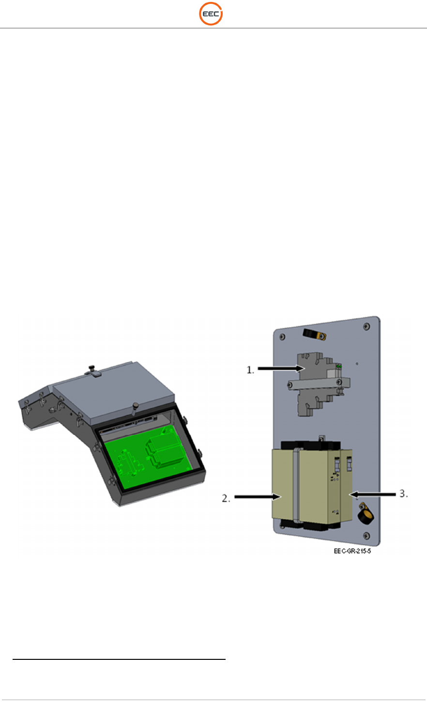
2.1.4.1.2. I/O Control Module (Unit 2 A1 A3 A1 A3)
The I/O Control Module contains the hardware used to monitor the various components within
the pedestal system. The I/O Control Module consists of the Analog and Discrete I/O modules
that are the heart of the BITE system and the main input for the RCU COBRA software. The
system utilizes loop-back monitoring on all channels where the inputs confirm output states for
increased system reliability. There are watchdog timers and failsafe outputs whereby a
communication fault sends output to a pre-defined state or holds the last value. Output fault
detection is selectable on individual channels.
Figure 33. I/O Control Module (135964-100)
2.1.4.1.2.1. Ethernet 16-Channel Discrete I/O Module (Unit 2 A1 A3 A1 A3 A1)
The 16-Channel Discrete (Digital) I/O (Input/Output) device has 16 bi-directional channels
available supporting an input/output mix in a single unit. It has a very small footprint. All 16-
channels update in 1ms. The unit is programmable trough a web-based user interface described
in Volume 1, Section 4, Vendor Documentation.
The system utilizes loop-back monitoring on all channels where the inputs confirm output states
for increased system reliability. There are watchdog timers and failsafe outputs whereby a
T
ECHNICAL
D
OCUMENTATION
P
ROTECTING
P
EOPLE AND
A
SSETS
®
D
ATE
:
27
M
ARCH
2017
|
V
ERSION
:
1.8
44
R
ANGER
®
-
X5
R
ADAR
S
YSTEM
(M
OBILE
)
F
UNCTIONAL
O
VERVIEW AND
T
HEORY OF
O
PERATION
EEC
®
|
C
OMPANY
P
ROPRIETARY
communication fault sends output to a pre-defined state or holds the last value. Output fault
detection is selectable on individual channels.
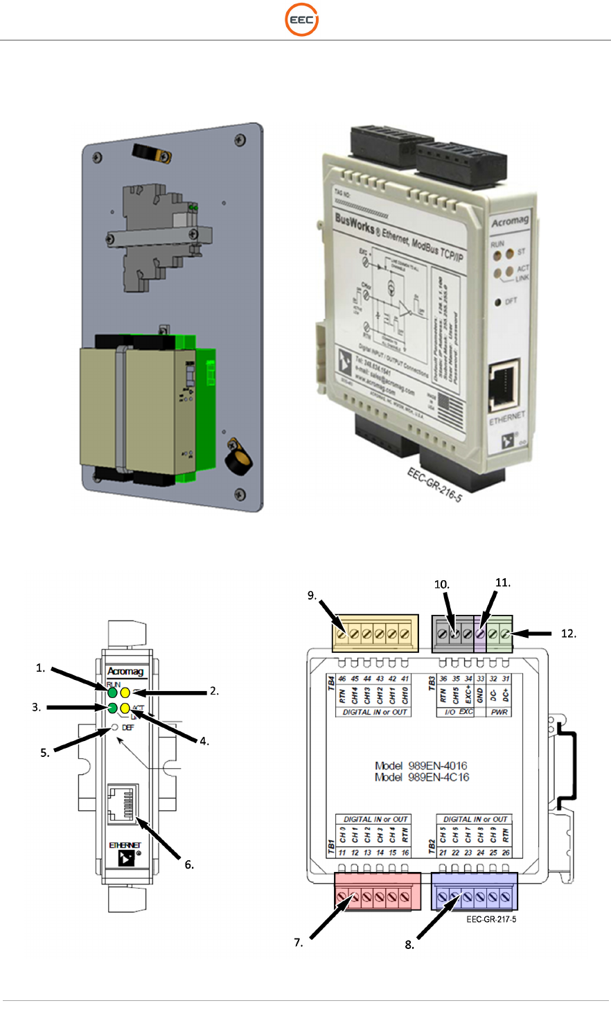
Figure 34. Ethernet 16-Channel Discrete I/O Module (132849-100) - Position
Figure 35. Ethernet 16-Channel Discrete I/O Module (132849-100) – Connections
T
ECHNICAL
D
OCUMENTATION
P
ROTECTING
P
EOPLE AND
A
SSETS
®
D
ATE
:
27
M
ARCH
2017
|
V
ERSION
:
1.8
45
R
ANGER
®
-
X5
R
ADAR
S
YSTEM
(M
OBILE
)
F
UNCTIONAL
O
VERVIEW AND
T
HEORY OF
O
PERATION
EEC
®
|
C
OMPANY
P
ROPRIETARY
1.
Run / Power LED (Green)
2. Status LED (Yellow)
3. Ethernet Link (Green)
4. Activity LED (Yellow)
5. Default Address Button
6. RJ45 Ethernet Connector
7. Terminal Block 1
8. Terminal Block 2
9. Terminal Block 4
10. Terminal Block 3
11. Ground
12. DC Power
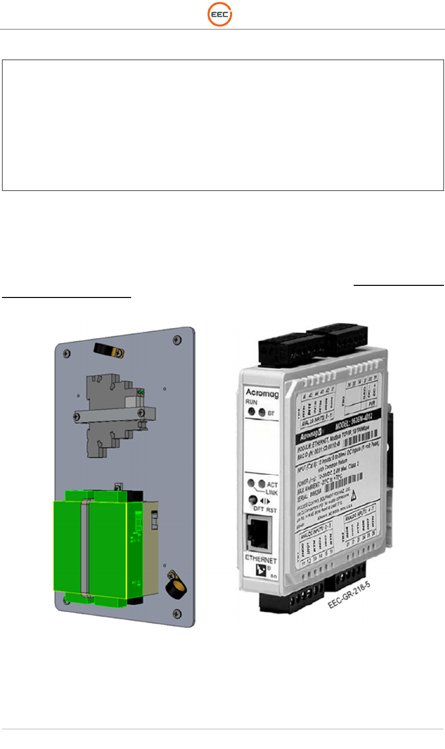
2.1.4.1.2.2. Ethernet 12-Channel Analog I/O Module (Unit 2 A1 A3 A1 A3 A2)
The 12-Channel Analog modules provide an isolated Ethernet network interface for analog input
channels. They have multi-range inputs to accept signals from a variety of sensors and devices.
They are high-resolution, low noise, A/D converters to deliver high accuracy and reliability.
This unit is programmable through a web-based user interface described in Volume 1, Section
4, Vendor Documentation.
Figure 36. Ethernet 12-Channel Analog I/O Module (132839-100) – Position
T
ECHNICAL
D
OCUMENTATION
P
ROTECTING
P
EOPLE AND
A
SSETS
®
D
ATE
:
27
M
ARCH
2017
|
V
ERSION
:
1.8
46
R
ANGER
®
-
X5
R
ADAR
S
YSTEM
(M
OBILE
)
F
UNCTIONAL
O
VERVIEW AND
T
HEORY OF
O
PERATION
EEC
®
|
C
OMPANY
P
ROPRIETARY
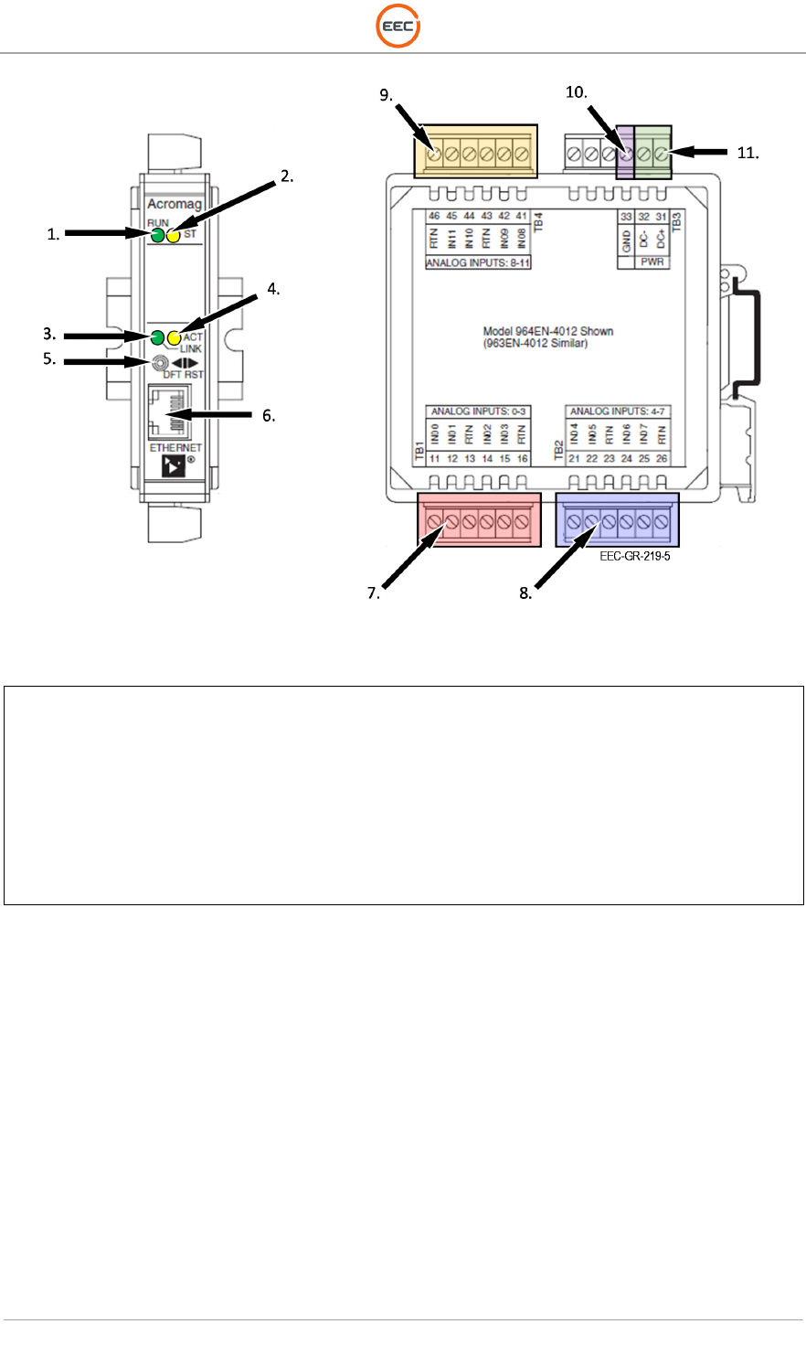
Figure 37. Ethernet 12-Channel Analog I/O Module (132839-100) – Position
1.
Run/Power LED (GREEN)
2. Module Status LED (YELLOW)
3. Ethernet Activity LED (YELLOW)
4. Link LED (GREEN)
5. Reset / Default Address Toggle Switch
6. RJ45 Ethernet Connector
7. I/O Port (CH0-3)
8. I/O Port (CH4-7)
9. I/O Port (CH8-11)
10. Ground
11. DC Power
T
ECHNICAL
D
OCUMENTATION
P
ROTECTING
P
EOPLE AND
A
SSETS
®
D
ATE
:
27
M
ARCH
2017
|
V
ERSION
:
1.8
47
R
ANGER
®
-
X5
R
ADAR
S
YSTEM
(M
OBILE
)
F
UNCTIONAL
O
VERVIEW AND
T
HEORY OF
O
PERATION
EEC
®
|
C
OMPANY
P
ROPRIETARY
2.1.4.1.3. Cold Plate, Weatherized (Unit 2 A1 A3 A1 A4)
The weatherized Cold Plate provides direct cooling to the IQ2-IFD Assembly. The thermal
stability of the IQ2-IFD is extremely important. The Cold Plate Assembly provides all of the
required cooling and environmental stability for the IF2-IFD.
Figure 38. Cold Plate (CP-3354)
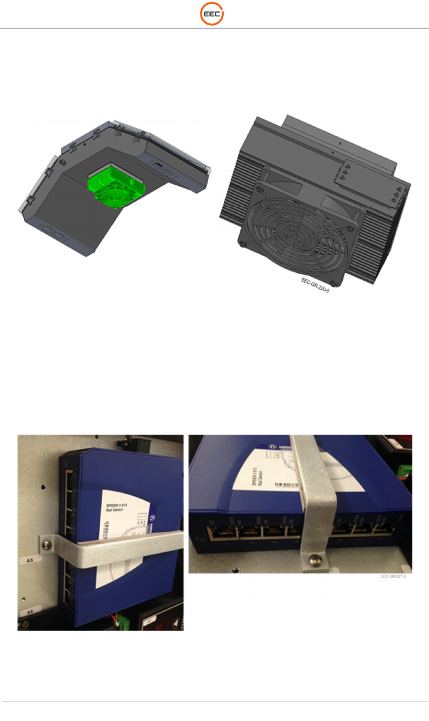
2.1.4.1.4. 8-Port Ethernet Switch (Unit 2 A1 A3 A1 A5)
The 8-Port Ethernet Switch is in a rugged, compact, DIN rail mount housing. It features passive
fan-less cooling and redundant 12/24VDC connections ensure high network availability. The
configuration data can be saved and restored through a serial interface, if necessary. This feature
permits for extremely low mean time to recover/replace (MTTR) values in the event of any
failures.
Figure 39. 8-Port Ethernet Switch (Spider 8TX)

T
ECHNICAL
D
OCUMENTATION
P
ROTECTING
P
EOPLE AND
A
SSETS
®
D
ATE
:
27
M
ARCH
2017
|
V
ERSION
:
1.8
48
R
ANGER
®
-
X5
R
ADAR
S
YSTEM
(M
OBILE
)
F
UNCTIONAL
O
VERVIEW AND
T
HEORY OF
O
PERATION
EEC
®
|
C
OMPANY
P
ROPRIETARY
2.1.4.1.5. Peltier Device Temperature Controller (Unit 2 A1 A3 A1 A6, A7)
The TC‐48‐20 is thermoelectric temperature controller capable of controlling up to 50 volts and
20 amps. Housed in a die‐cast aluminum box, it incorporates a keypad and a liquid‐crystal
display capable of displaying two lines of text, each up to 16 characters long. The display allows
the user to monitor the sensor temperature, output level, and menu settings. The integrated
keypad accesses an easy‐to‐use menu system, allowing the user to adjust all of the basic
controller parameters such as the set temperature, tuning parameters, and alarm parameters.
There are two TC-48-20 devices. One connects to the Weatherized Cold Plate (Unit 2 A1 A3 A1
A4) on the IQ2-IFD and the other connects to the Weatherized Liquid Cooler (Unit 2 A1 A4 A6).
Figure 40. Peltier Temperature Controller (TC-48-20)
1.
Menu Button
2. Decrease Parameter (Down Arrow)
3. Increase Parameter (Up Arrow)
4. LCD Display
T
ECHNICAL
D
OCUMENTATION
P
ROTECTING
P
EOPLE AND
A
SSETS
®
D
ATE
:
27
M
ARCH
2017
|
V
ERSION
:
1.8
49
R
ANGER
®
-
X5
R
ADAR
S
YSTEM
(M
OBILE
)
F
UNCTIONAL
O
VERVIEW AND
T
HEORY OF
O
PERATION
EEC
®
|
C
OMPANY
P
ROPRIETARY
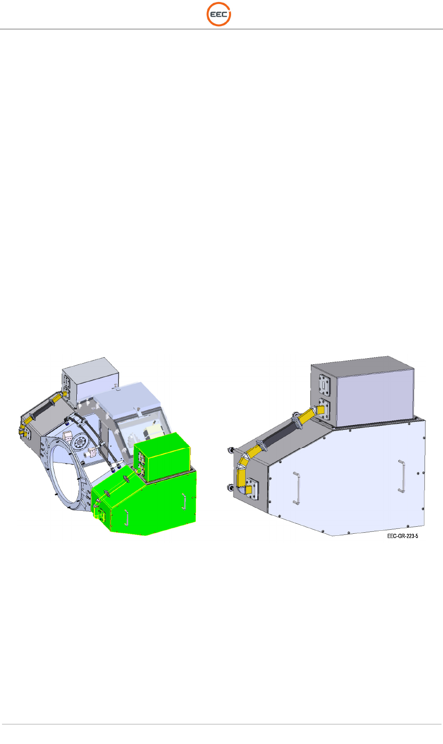
2.1.4.2. Transceiver Assembly (Horizontal) (Unit 2 A1 A3 A2)
The Ranger-X5 transmitter employs an X-band solid-state amplifier as the stable, power device.
Mounted within the saddle of the radar pedestal are the transceiver assembly subsystems. The
SIDPOL® model has two units—one Horizontal and one Vertical (see paragraph Error!
Reference source not found.). The Transceiver Assembly houses:
• 500 Watt Power Amplifier (Unit 2 A1 A2 A1)
• RF Up/Down Converter (UDC) / Transmitter Control Assembly (Unit 2 A1 A2 A2)
• Transceiver Power Supply (Unit 2 A1A2 A3)
• Temperature Humidity Sensor (Unit 2 A1 A2 A4)
• Cross Guide Coupler (Unit 2 A1 A2 DC1)
• 3-Port Circulator (Unit 2 A1 A2 HY1)
• TR Limiter (Unit 2 A2 V1)
The Transmitter Control Assembly includes an RF coupler that allows the burst signal to pass
through the down-conversion network for sampling by the IQ2-IFD Intermediate Frequency
Digitizer (digital receiver). In order for pulse compression algorithms to approach theoretical
performance, the transmit signal waveforms must be known and used by the matched filter during
the received signal processing stage.
The Power Amplifier is a compact 500W solid-state power amplifier (SSPA) housed within the
Transmitter Assembly. The Transmitter Control Assembly incorporates other radar front-end
components (LNA, RF Amplifier, Signal Generator). Utilizing pulse widths of up to 100µs, the
Transceiver Assembly allows the Ranger-X5 Radar to achieve sensitivity levels comparable to
that of a 250kW transmitter with a 1µs pulse (assuming 100:1 pulse compression ratio).
Figure 41. Horizontal Transceiver Assembly (135895-100)

T
ECHNICAL
D
OCUMENTATION
P
ROTECTING
P
EOPLE AND
A
SSETS
®
D
ATE
:
27
M
ARCH
2017
|
V
ERSION
:
1.8
50
R
ANGER
®
-
X5
R
ADAR
S
YSTEM
(M
OBILE
)
F
UNCTIONAL
O
VERVIEW AND
T
HEORY OF
O
PERATION
EEC
®
|
C
OMPANY
P
ROPRIETARY
2.1.4.2.1. 500W Power Amplifier (Unit 2 A1 A3 A2 A1)
A 500-watt X-band solid-state provides higher duty cycles and greater sensitivity despite
transmitting at significantly lower powers. The Ranger-X5 is capable of producing waveforms with
duty cycles up to 15% and pulse widths up to 100-µsec utilizing pulse compression technology.
The Transmitter Control Unit (Unit 2 A1 A2 A2) provides the control and trigger signals necessary
for amplification within the Power Amplifier.
The Transmitter Assembly is comprised of a series of six (6) 100W Solid-State Power Amplifiers
and a power combiner providing a minimum of 500 watts of power at the output of the power
amplifier.
Figure 42. 500W Power Amplifier (134325-500)
T
ECHNICAL
D
OCUMENTATION
P
ROTECTING
P
EOPLE AND
A
SSETS
®
D
ATE
:
27
M
ARCH
2017
|
V
ERSION
:
1.8
51
R
ANGER
®
-
X5
R
ADAR
S
YSTEM
(M
OBILE
)
F
UNCTIONAL
O
VERVIEW AND
T
HEORY OF
O
PERATION
EEC
®
|
C
OMPANY
P
ROPRIETARY
2.1.4.2.2. Horizontal UDC / Transmitter Control (Unit 2 A1 A3 A2 A2)
The Ranger-X5 combines the up and down conversion subsystem into a single unit. The UDC
translates information between the intermediate frequency (IF) and X-band operating
frequencies. It utilizes low-noise amplifiers (LNA), RF Amplifiers, IF Amplifiers, a Frequency
Multiplier (on Horizontal Assembly Only), and a Signal Generator (on Horizontal Assembly Only).
The frequency multiplier and signal generator also provide signals for the Vertical Channel.
Figure 43. UDC / Transmitter Control Assembly (135898-100) – Horizontal
The IQ2-IFD (Unit 2 A1 A3 A1 A1) generates the waveform at the IF frequency of 60MHz that
drives the shape of the waveform for the UDC. The Signal Generator (Unit 2 A1 A3 A2 A2 A6)
provides the RF Frequency and bandwidth of the transmit frequency. The waveform and
frequency mix in the Image Reject mixer before and route to the RF Amplifier (Unit 2 A1 A3 A2
A2 A1). From the RF Amplifier, the RF signal (waveform and frequency) route to the 500W
Power Amplifier (Unit 2 A1 A3 A2 A1) for final amplification and pulse transmission into the
waveguide system.
The UDC is a breakthrough in achieving excellent performance of image rejection (without narrow
band filters in the module or multiple conversion states), TR isolation, and phase noise in an
integrated module. This UDC design combines a very simple conversion structure and image-
rejection mixer technology, which achieves strong image rejection performance without onboard
filters or multiple stages of conversion. This technology also helps reduce complexity and
minimize space requirements. The shielded RF enclosure helps to achieve the required level of
TR isolation.
T
ECHNICAL
D
OCUMENTATION
P
ROTECTING
P
EOPLE AND
A
SSETS
®
D
ATE
:
27
M
ARCH
2017
|
V
ERSION
:
1.8
52
R
ANGER
®
-
X5
R
ADAR
S
YSTEM
(M
OBILE
)
F
UNCTIONAL
O
VERVIEW AND
T
HEORY OF
O
PERATION
EEC
®
|
C
OMPANY
P
ROPRIETARY
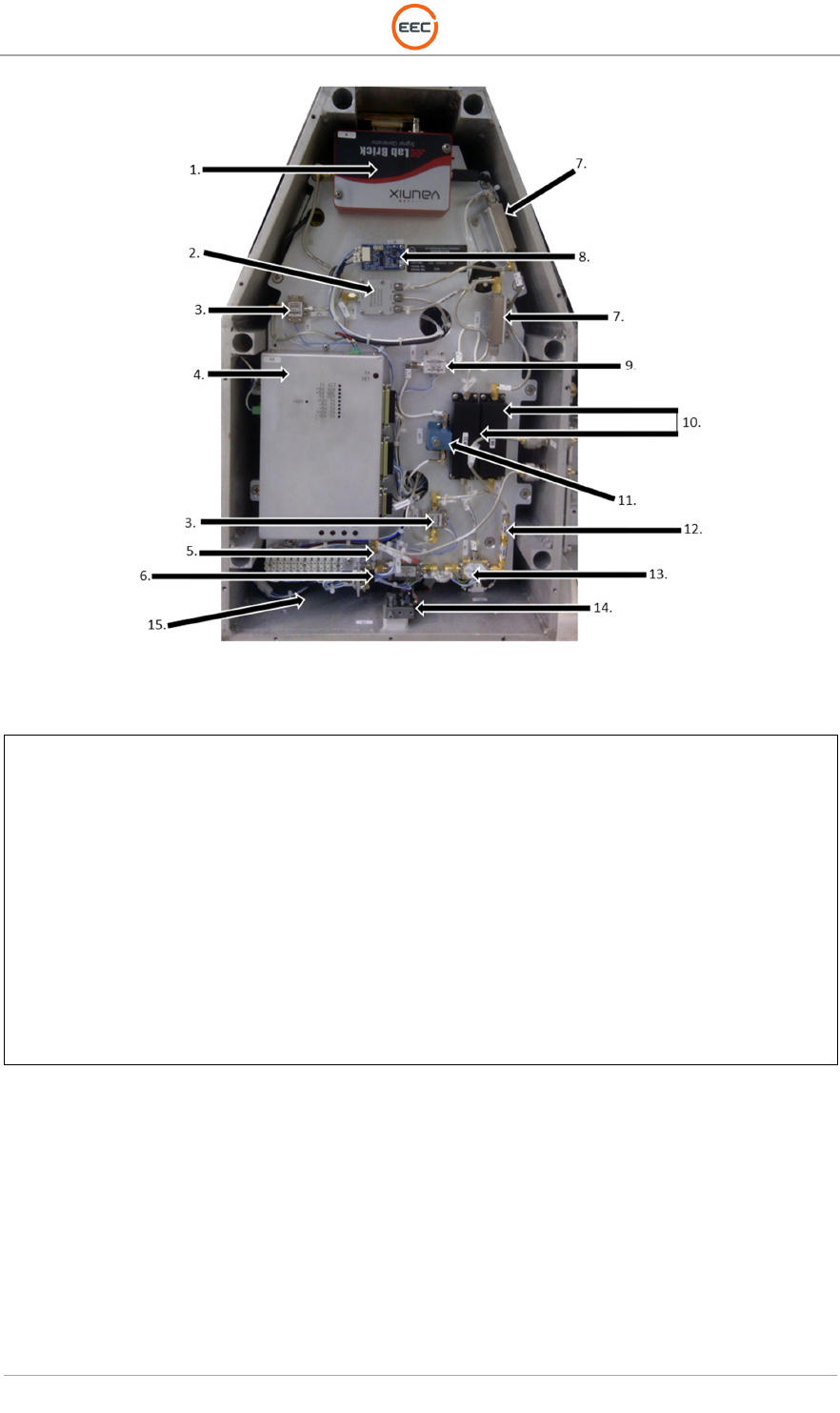
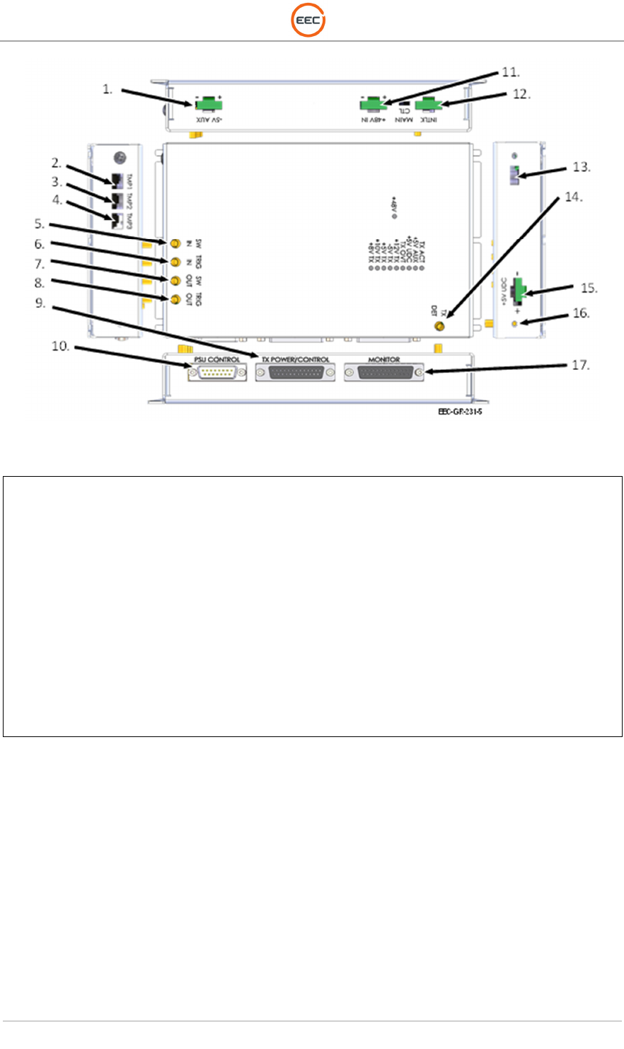
Figure 44. UDC / Transmitter Control (135898-100)
1.
Signal
Generator, LMS
-
103
2. Power Divider, RFLT3WG18G
3. Coaxial RF Amplifier, ZVA-183X-S+
4. Transceiver Power Supply, 134728-100 (NOT AN RF COMPONENT)
5. PIN Diode Limiter, LP7012
6. X-Band LNA, CA910-259L
7. Image Reject Mixer, IRM0812LC2B-1
8. Temperature / Humidity Sensor, 134951-100 (NOT AN RF COMPONENT)
9. IF Amplifier, ZJL-7G
10. Narrow Bandwidth Cavity Filters, 3C60-9275/U10-0/0
11. Variable Attenuator, ARM-1
12. Coaxial Attenuator, BW-S40W2
13. Coaxial Switch, S2X1-1-5
14. Interlock Switch (NOT AN RF COMPONENT)
15. Cooling Fan (NOT AN RF COMPONENT)
16. 2-Way Splitter, ZFSC-2-10G
2.1.4.2.2.1. LNA, X-Band (Unit 2 A1 A3 A2 A2 A1)
(See Figure 44, Point 6) - (CA910-259L)
The LNA is a solid-state device to amplify the very weak return signal with a minimal contribution
to the overall noise figure of the receiver. The primary characteristic of an LNA is the noise figure,
a measure of how much the LNA degrades the signal-to-noise ratio of the received signal. Other
important characteristics of the LNA are linearity (measured in P1dB or third order intercept), the
survivable input power, and the DC dissipation.

T
ECHNICAL
D
OCUMENTATION
P
ROTECTING
P
EOPLE AND
A
SSETS
®
D
ATE
:
27
M
ARCH
2017
|
V
ERSION
:
1.8
53
R
ANGER
®
-
X5
R
ADAR
S
YSTEM
(M
OBILE
)
F
UNCTIONAL
O
VERVIEW AND
T
HEORY OF
O
PERATION
EEC
®
|
C
OMPANY
P
ROPRIETARY
2.1.4.2.2.2. Coaxial RF Amplifier ((Unit 2 A1 A3 A2 A2 A2, A3)
(See Figure 44, Point 3) - (ZVA-183X-S+)
The RF Amplifier is a stable and power wideband amplifier (typically +33dBm). It will provide 24
to 26dB of gain to the output signal unit with a high output.
2.1.4.2.2.3. IF Amplifier (Unit 2 A1 A3 A2 A2 A4)
(See Figure 44, Point 9) - (ZJL-7G)
The IF Amplifier is a stable and power wideband amplifier. It will provide 8 to 10dB of gain to the
input signal unit with a high output.
2.1.4.2.2.4. Signal Generator (Unit 2 A1 A3 A2 A2 A6)
The Lab Brick LMS-103 is a USB-compatible synthesized signal generator that covers
frequencies from 5000MHz to 10000MHz. It has low phase noise, fast 100 microsecond
switching time, and fine 100 Hz frequency resolution. It requires no additional DC supply voltage
and has features such as phase continuous linear frequency sweeping, internal/external 10 MHz
reference, and optional pulse modulation.
Figure 45. Signal Generator (LMS-103)
2.1.4.2.2.5. PIN Diode Limiter (Unit 2 A1 A3 A2 A2 V1)
(See Figure 44, Point 6) - (LP7012)
The PIN Diode Limiter is a protective unit within the RF signal flow to protect the LNA from power
overload.
2.1.4.2.3. Transceiver Power Supply Unit (Unit 2 A1 A3 A2 A3)
The Transceiver Power Supply Unit provides power to the Transceiver Units and the UDC. Status
of the Transceiver Power Supply Unit routes through the I/O modules.
T
ECHNICAL
D
OCUMENTATION
P
ROTECTING
P
EOPLE AND
A
SSETS
®
D
ATE
:
27
M
ARCH
2017
|
V
ERSION
:
1.8
54
R
ANGER
®
-
X5
R
ADAR
S
YSTEM
(M
OBILE
)
F
UNCTIONAL
O
VERVIEW AND
T
HEORY OF
O
PERATION
EEC
®
|
C
OMPANY
P
ROPRIETARY
Figure 46. Transceiver Power Supply (134728-100)
1.
Not Used
2. Not Used
3. Not Used
4. Not Used
5. Factory Use ONLY
6. Factory Use ONLY
7. Factory Use ONLY
8. Factory Use ONLY
9. Transmitter Power and Control
10. Power Supply Unit Control
11. +48 VDC Power Input
12. Not Used
13. Not Used
14. Factory Use ONLY
15. +5 VDC Power Output to UDC
16. Ground Point
17. Servo Controller Output
2.1.4.2.4. Temperature / Humidity Sensor (Unit 2 A1 A3 A2 A4)
The Temperature / Humidity sensor provides continuous, instantaneous feedback of the
environmental conditions in the Horizontal Transceiver Assembly.
T
ECHNICAL
D
OCUMENTATION
P
ROTECTING
P
EOPLE AND
A
SSETS
®
D
ATE
:
27
M
ARCH
2017
|
V
ERSION
:
1.8
55
R
ANGER
®
-
X5
R
ADAR
S
YSTEM
(M
OBILE
)
F
UNCTIONAL
O
VERVIEW AND
T
HEORY OF
O
PERATION
EEC
®
|
C
OMPANY
P
ROPRIETARY
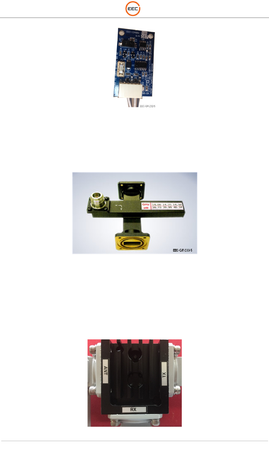
Figure 47. Temperature Humidity Sensor (134951-100)
2.1.4.2.5. Crossguide Coupler (Unit 2 A1 A3 A2 DC1)
The Crossguide Coupler provide a point of connection for sampling the power of the transmit
burst before it reaches the circulator.
Figure 48. Crossguide Coupler (609870)
2.1.4.2.6. 3-Port Circulator (Unit 2 A1 A3 A2 HY1)
The function of the circulator is to provide isolation from the output of the circulator (port 2) and
the input of the circulator (port 1). This isolation safeguards the receiver components from a
mismatch occurring which may damage the ceramic output window. The third port (port 3)
provides a connection point for the TR Limiter (Unit 2 A1 A3 A2 V1) to protect the critical low
power receiver components from the higher power of the transmit signal.
Figure 49. 3-Port Circulator (135862-100)
T
ECHNICAL
D
OCUMENTATION
P
ROTECTING
P
EOPLE AND
A
SSETS
®
D
ATE
:
27
M
ARCH
2017
|
V
ERSION
:
1.8
56
R
ANGER
®
-
X5
R
ADAR
S
YSTEM
(M
OBILE
)
F
UNCTIONAL
O
VERVIEW AND
T
HEORY OF
O
PERATION
EEC
®
|
C
OMPANY
P
ROPRIETARY
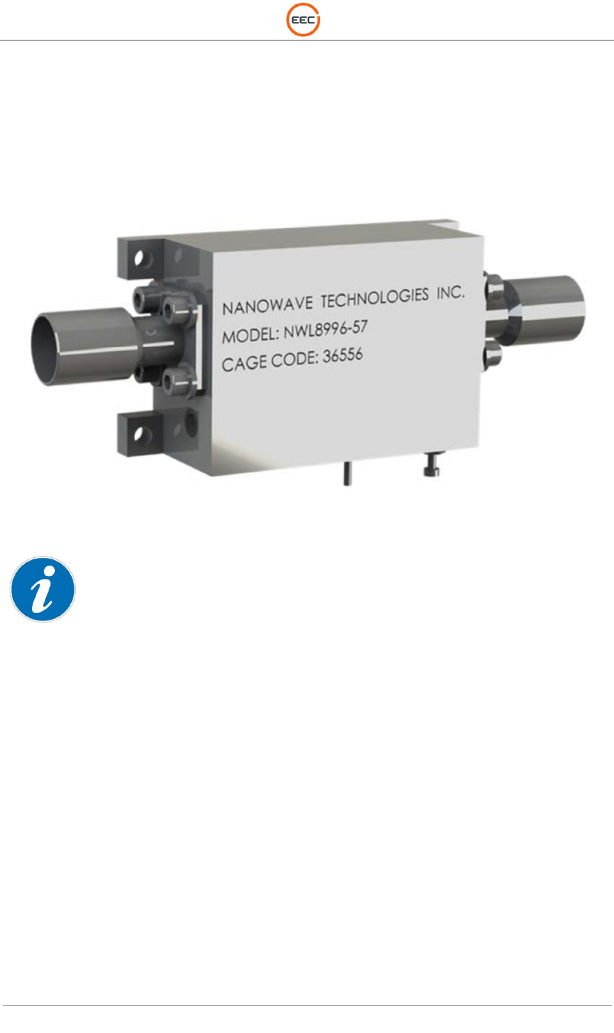
2.1.4.2.7. TR Limiter (Unit 2 A1 A3 A2 V1)
The Ranger-X5 radar system has a Transmit/Receive (TR) Limiter that contain a small amount
of tritium (see Volume 1, Section 4, Vendor Documentation). The TR Limiter protects the
sensitive receiver components from the high-energy burst of the transmit RF burst. The TR
Limiter is a passive device.
Figure 50. TR Limiter (NWLIM8896-57)
The receiver protector tubes are individually sealed units and normal handling does not
present
any
radioactive problems. The manufacture of TR Limiters complies with 49 CFR 173.422. The TR Limiters are
parts in compliance with 29 CFR 1910.1200. The TR Limiters are classified as “electron tubes” in compliance
with 10 CFR 30.15 (a) (8). See Volume 1, Section 4, Vendor Documentation for the Material Safety Data
Sheet (MSDS), which includes information about special care and disposal of the TR Limiter.
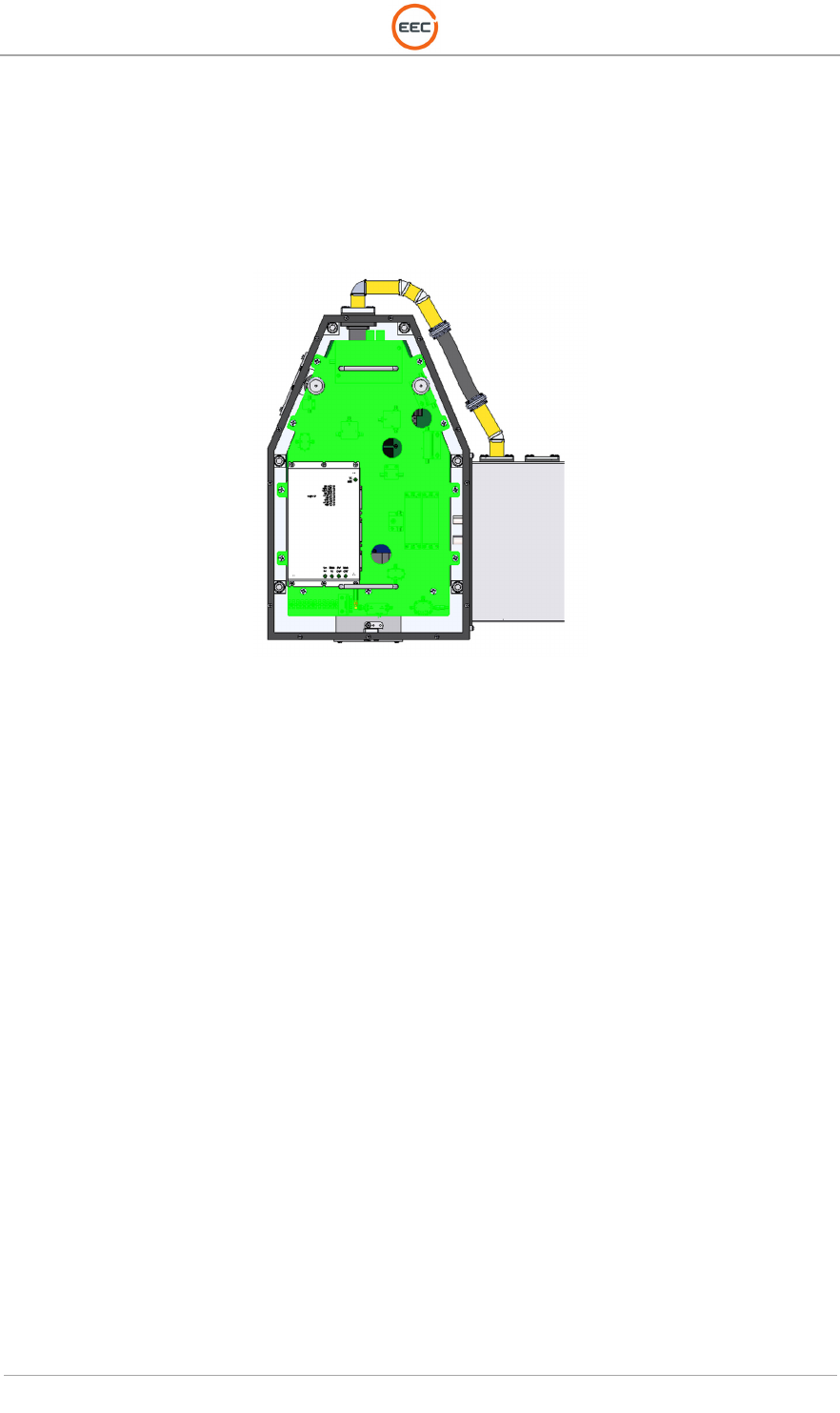
2.1.4.3. Transceiver Assembly (Vertical) (Unit 2 A1 A3 A3)
The Vertical Transceiver Assembly is identical to the Horizontal Transceiver Assembly (see
paragraph Error! Reference source not found.. The Vertical Transceiver Assembly does not
have the following components:
• Frequency Multiplier
• Signal Generator
Other than these two components, the Vertical Transceiver Assembly is identical in every way to
the Horizontal Transceiver Assembly.

T
ECHNICAL
D
OCUMENTATION
P
ROTECTING
P
EOPLE AND
A
SSETS
®
D
ATE
:
27
M
ARCH
2017
|
V
ERSION
:
1.8
57
R
ANGER
®
-
X5
R
ADAR
S
YSTEM
(M
OBILE
)
F
UNCTIONAL
O
VERVIEW AND
T
HEORY OF
O
PERATION
EEC
®
|
C
OMPANY
P
ROPRIETARY
Figure 51. Vertical Transceiver Assembly (135891-100)
2.1.4.3.1. 500W Power Amplifier (Unit 2 A1 A3 A3 A1)
Identical to the Horizontal Unit – see paragraph 2.1.4.2.1.
2.1.4.3.2. Vertical UDC / Transmitter Control (Unit 2 A1 A3 A3 A2)
Identical to the Horizontal Unit - see Paragraph 2.1.4.2.2.
2.1.4.3.2.1. LNA, X-Band (Unit 2 A1 A3 A3 A2 A1)
Identical to the Horizontal Unit – see Paragraph 2.1.4.2.2.1.
2.1.4.3.2.2. Coaxial RF Amplifier (Unit 2 A1 A3 A3 A2 A2)
Identical to the Horizontal Unit - see Paragraph 2.1.4.2.2.2.
2.1.4.3.2.3. IF Amplifier (Unit 2 A1 A3 A3 A2 A3)
Identical to the Horizontal Unit - see Paragraph 2.1.4.2.2.3.Error! Reference source not found.
2.1.4.3.2.4. PIN Diode Limiter (Unit 2 A1 A3 A3 A3 V1)
Identical to the Horizontal Unit - see Paragraph Error! Reference source not found.1.4.2.2.5.
2.1.4.3.3. Transceiver Power Supply Unit (Unit 2 A1 A3 A3 A3)
Identical to the Horizontal Unit - see Paragraph Error! Reference source not found.2.1.4.2.3.
2.1.4.3.4. Temperature / Humidity Sensor (Unit 2 A1 A3 A3 A4)
Identical to the Horizontal Unit - see Paragraph 2.1.4.2.4
T
ECHNICAL
D
OCUMENTATION
P
ROTECTING
P
EOPLE AND
A
SSETS
®
D
ATE
:
27
M
ARCH
2017
|
V
ERSION
:
1.8
58
R
ANGER
®
-
X5
R
ADAR
S
YSTEM
(M
OBILE
)
F
UNCTIONAL
O
VERVIEW AND
T
HEORY OF
O
PERATION
EEC
®
|
C
OMPANY
P
ROPRIETARY
2.1.4.3.5. Crossguide Coupler (Unit 2 A1 A3 A3 DC1)
Identical to the Horizontal Unit - see Paragraph 2.1.4.2.5.
2.1.4.3.6. 3-Port Circulator (Unit 2 A1 A3 A3 HY1)
Identical to the Horizontal Unit - see Paragraph 2.1.4.2.6.
2.1.4.3.7. TR Limiter (Unit 2 A1 A3 A3 V1)
Identical to the Horizontal Unit - see Paragraph 2.1.4.2.7.
2.1.4.4. Fluid Pump Assembly (Unit 2 A1 A3 A4)
The Transceiver Systems operate at a very high temperature. Simple “air cooling” techniques
found in other radar systems are not sufficient for extracting heat away from the Transmitter. To
enhance and improve the cooling capability, EEC employs a Liquid Cooling Assembly to remove
excess heat from the Transceiver units. The Liquid Cooling Assembly consists of a Weatherized
Liquid Cooler utilizing a Peltier device and a Fluid Pump Assembly. The liquid is standard
automotive antifreeze (Ethylene Glycol, Propylene Glycol or Glycerol) that can be purchased
worldwide at any automotive parts supplier.
The Fluid Pump Assembly moves the liquid through the cooling system. The Weatherized Liquid
Cooler unit (See paragraph Error! Reference source not found.) acts as the heat exchanger.
Figure 52. Fluid Pump Assembly (135118-100)
2.1.4.5. Weatherized Liquid Cooler (Unit 2 A1 A4 A6)
The Liquid Cooler is the heat exchanger unit of the Liquid Cooling System. This unit performs
the same duties as a radiator in an automobile.
T
ECHNICAL
D
OCUMENTATION
P
ROTECTING
P
EOPLE AND
A
SSETS
®
D
ATE
:
27
M
ARCH
2017
|
V
ERSION
:
1.8
59
R
ANGER
®
-
X5
R
ADAR
S
YSTEM
(M
OBILE
)
F
UNCTIONAL
O
VERVIEW AND
T
HEORY OF
O
PERATION
EEC
®
|
C
OMPANY
P
ROPRIETARY
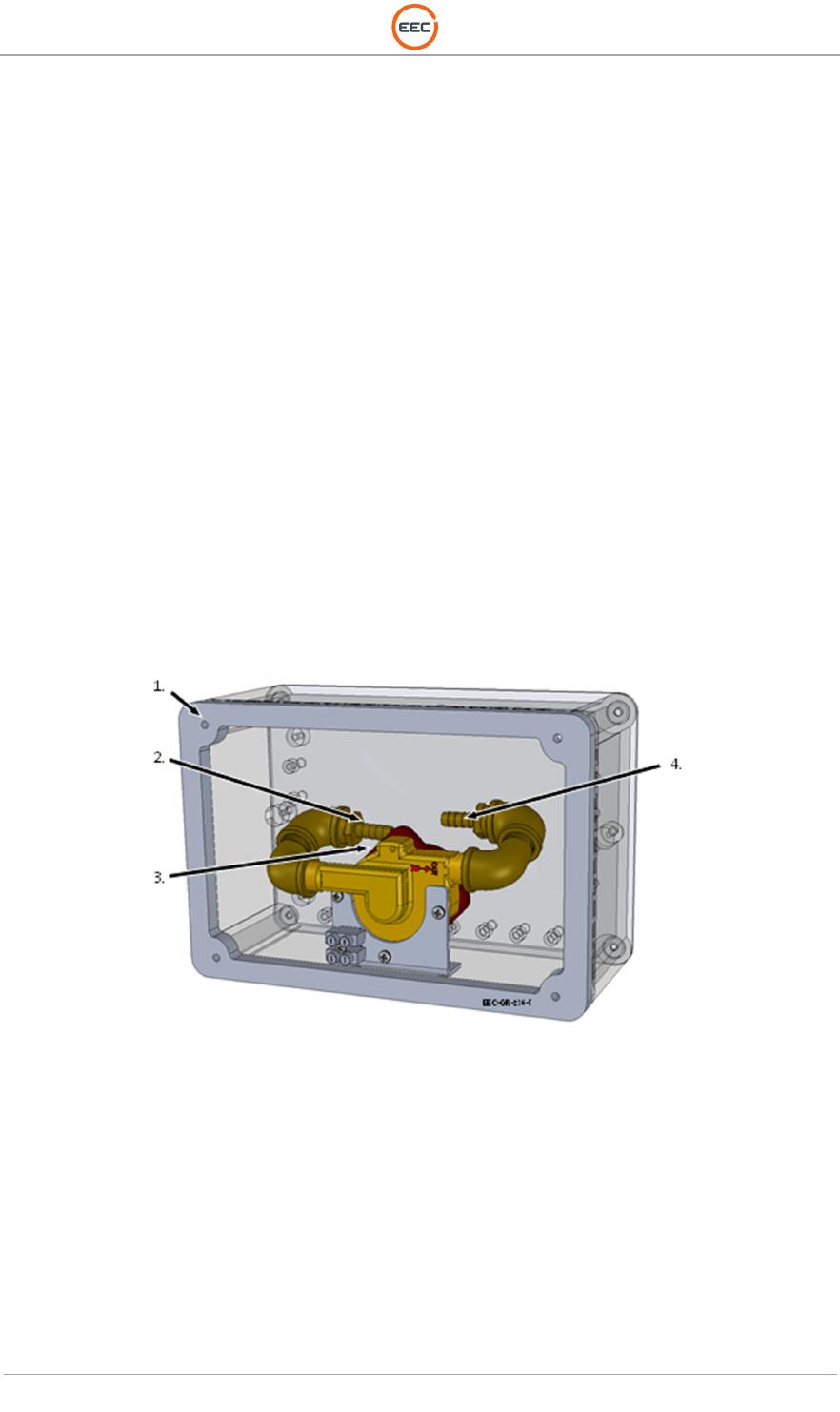
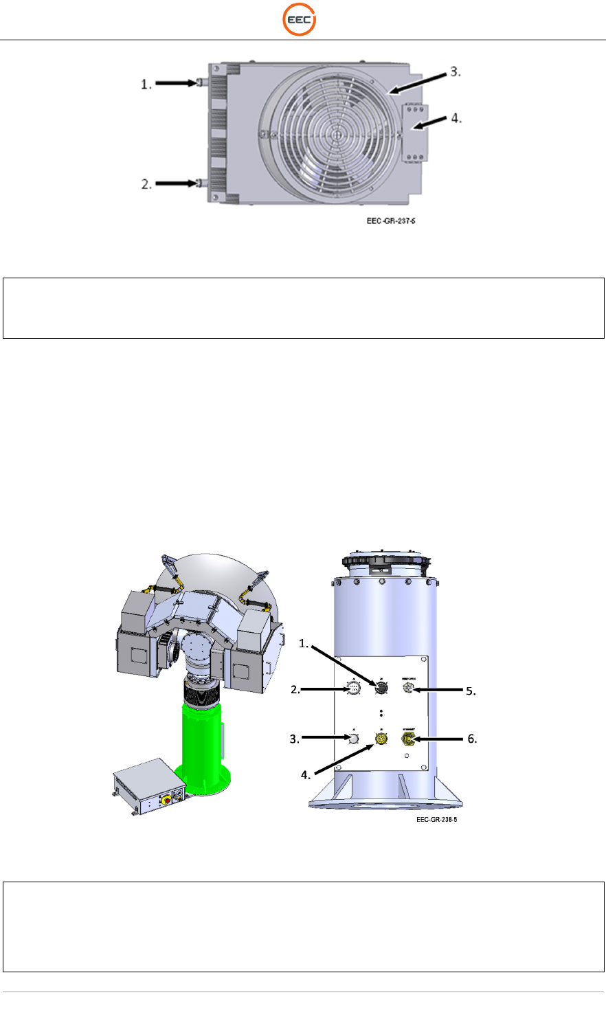
Figure 53. Weatherized Liquid Cooler (LC-3356)
1.
Coolant In
2. Coolant Out
3. Cooling Fan
4. Terminal Connector
2.1.5. V-Clamp Pedestal Assembly (Unit 2 A1 A4)
The V-Clamp Pedestal Assembly is also called the “Riser.” The Riser provides a rigid mounting
platform for the Payload Support Assembly (Unit 2 A1 A3). There are connectors on the riser
connecting the Pedestal Plate Enclosure Assembly (Unit 2 A1 A5) to the Riser. Internally, there
is wiring to connect the Payload Support Assembly to the connector panel. There are also holes
in the base of the riser for connecting the assembly to the mounting surface and for leveling the
unit to the mounting surface.
Figure 54. V-Clamp Pedestal Assembly (135892-100)
1.
J4. Signal Cable
2. J3. DC Power
3. J5. Drive Power Cable
4. J6. Drive Encoder and Rotary Sensor
5. Fiber Optic Cable Gland
6. Ethernet
T
ECHNICAL
D
OCUMENTATION
P
ROTECTING
P
EOPLE AND
A
SSETS
®
D
ATE
:
27
M
ARCH
2017
|
V
ERSION
:
1.8
60
R
ANGER
®
-
X5
R
ADAR
S
YSTEM
(M
OBILE
)
F
UNCTIONAL
O
VERVIEW AND
T
HEORY OF
O
PERATION
EEC
®
|
C
OMPANY
P
ROPRIETARY
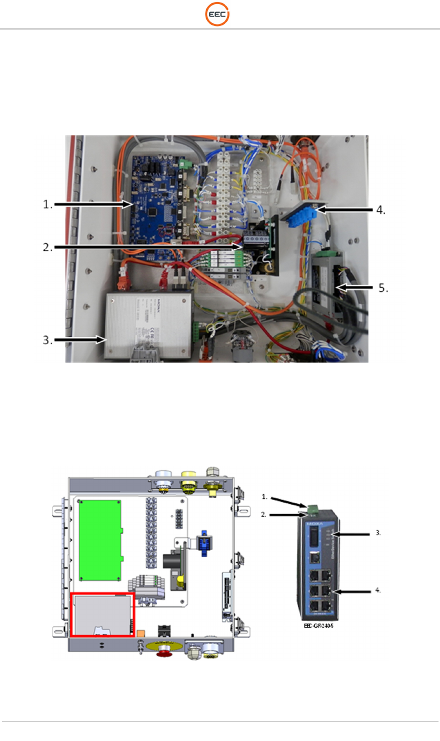
2.1.6. Pedestal Enclosure Plate Assembly (Unit 2 A1 A5)
The Pedestal Enclosure Plate Assembly contains the Azimuth Servo Controller and Power
Amplifier, the Ethernet Communications, the Fiber Optic Ports and the Azimuth Regeneration
Clamp.
Figure 55. Pedestal Enclosure Plate Assembly
2.1.6.1. 7-Port Ethernet Switch with 1-Fiber Optic Port (Unit 2 A1 A5 A1)
The Ethernet Switch is an industrial grade Gigabit Ethernet connection with built-in relay warning
function that provides information to the BITE system when power failures or port breaks occur.
Figure 56. Ethernet Switch (EDS-308-M-SC-T)
See Paragraph 1.1.8.1 for more details.