Enterprise Electronics RANGERX5 Ranger-X5 RADAR User Manual Section 2 Troubleshooting Maintenance Calibration v1 4 DRAFT 002
Enterprise Electronics Corporation Ranger-X5 RADAR Section 2 Troubleshooting Maintenance Calibration v1 4 DRAFT 002
Contents
- 1. User Manual Troubleshooting Maintenance Calibration Part 1
- 2. User Manual Troubleshooting Maintenance Calibration Part 2
- 3. User Manual Overview Theory Part 2
- 4. User Manual Overview Theory Part 1
- 5. User Manual Overview Theory Part 3
- 6. User Manual Overview Theory Part 4
User Manual Troubleshooting Maintenance Calibration Part 2

T
ECHNICAL
D
OCUMENTATION
P
ROTECTING
P
EOPLE AND
A
SSETS
®
D
ATE
:
22
M
ARCH
2017
|
V
ERSION
:
1.4
41
R
ANGER
-X5
R
ADAR
S
YSTEM
T
ROUBLESHOOTING
,
M
AINTENANCE
,
AND
C
ALIBRATION
EEC
®
|
C
OMPANY
P
ROPRIETARY
NO: Replace the Cold Plate.
Maintenance:
Cold Plate
1. Step 1:
Remove the cover from the Plenum Assembly by releasing the four quick-disconnect
latches and by loosening two Retaining Screws (see Figure 11), then remove the lid.
1. Step 2:
Disconnect and remove the IQ2-IFD Assembly (see Paragraph 2.1.3.1.1).
2. Step 3:
Loosen and remove the four (4) Philips head screws retaining the Cold Plate in Place.
Take care to retain the rubber seal for reuse.
3. Step 4:
Remove the Cold Plate from the Plenum Assembly.
4. Step 5:
Reinstall in reverse order of Steps 1-4.
Fan
1. Step 1:
Disconnect the fan from the power on the IQ2 PSU.
2. Step 2:
Loosen and remove the four (4) Philips head screws retaining the Fan to the Cold
Plate.
3. Step 3:
Pull the power cables through the opening.
4. Step 4:
Remove the Fan from the Cold Plate.

T
ECHNICAL
D
OCUMENTATION
P
ROTECTING
P
EOPLE AND
A
SSETS
®
D
ATE
:
22
M
ARCH
2017
|
V
ERSION
:
1.4
42
R
ANGER
-X5
R
ADAR
S
YSTEM
T
ROUBLESHOOTING
,
M
AINTENANCE
,
AND
C
ALIBRATION
EEC
®
|
C
OMPANY
P
ROPRIETARY
5. Step 5:
Reinstall in reverse order of Steps 1-4.
Calibration:
None
2.1.3.1.4. 8-Port Ethernet Switch (Unit 2 A1 A3 A1 A5)
Troubleshooting:
SD-135953-100 or -101 Sheet 3 of 4
If the Ethernet Communication within the Plenum Assembly or the Transmitter Assemblies is no
longer functioning, verify the power and Ethernet connectivity of the 8-Port Ethernet Switch. If it
is not functioning properly and power is available, replace the unit. If power is available but
Ethernet communication is not functioning, replace the unit.
Maintenance:
1. Step 1:
Remove the cover from the Plenum Assembly by releasing the four quick-disconnect
latches and by loosening two Retaining Screws (see Figure 11), then remove the lid.
2. Step 2:
Disconnect all power and Ethernet cables from the Switch Assembly.
3. Step 3:
Loosen and remove the four (4) Philips head screws holding the bracket that retain the
Ethernet Switch to the mounting plate (See Figure 13).
T
ECHNICAL
D
OCUMENTATION
P
ROTECTING
P
EOPLE AND
A
SSETS
®
D
ATE
:
22
M
ARCH
2017
|
V
ERSION
:
1.4
43
R
ANGER
-X5
R
ADAR
S
YSTEM
T
ROUBLESHOOTING
,
M
AINTENANCE
,
AND
C
ALIBRATION
EEC
®
|
C
OMPANY
P
ROPRIETARY
Figure 13. Ethernet Switch Retaining Brackets
4. Step 4:
Remove the Ethernet Switch from the Plenum Assembly.
5. Step 5:
Reinstall in reverse order of Steps 1-4.
Calibration:
None
2.1.3.1.5. Peltier Device Temperature Controller (Unit 2 A1 A3 A1 A6, A7)
Troubleshooting:
SD-135953-100 or -101 Sheet 1 of 4
Troubleshoot the Peltier Device Temperature Controller Use Vendor Documentation (See
Volume 2, Section 4, Paragraph 2.1.3.1.5)
Maintenance:
1. Step 1:
Remove the cover from the Plenum Assembly by releasing the four quick-disconnect
latches and by loosening two Retaining Screws (see Figure 11), then remove the lid.
T
ECHNICAL
D
OCUMENTATION
P
ROTECTING
P
EOPLE AND
A
SSETS
®
D
ATE
:
22
M
ARCH
2017
|
V
ERSION
:
1.4
44
R
ANGER
-X5
R
ADAR
S
YSTEM
T
ROUBLESHOOTING
,
M
AINTENANCE
,
AND
C
ALIBRATION
EEC
®
|
C
OMPANY
P
ROPRIETARY
2. Step 2:
Disconnect all power and cables from the Ethernet Controllers.
3. Step 3:
Loosen and remove the four (4) Philips head screws holding Controller to the mounting
plate (See Figure 14).
Figure 14. Temperature Controller Retaining Screws
4. Step 4:
Remove the Controller from the Plenum Assembly.
5. Step 5:
Reinstall in reverse order of Steps 1-4.
Calibration:
None
2.1.3.2. Transceiver Assembly (Horizontal) (Unit 2 A1 A3 A2)
Troubleshooting:
SD-135895-100 or SD-136033-100

T
ECHNICAL
D
OCUMENTATION
P
ROTECTING
P
EOPLE AND
A
SSETS
®
D
ATE
:
22
M
ARCH
2017
|
V
ERSION
:
1.4
45
R
ANGER
-X5
R
ADAR
S
YSTEM
T
ROUBLESHOOTING
,
M
AINTENANCE
,
AND
C
ALIBRATION
EEC
®
|
C
OMPANY
P
ROPRIETARY
SD-135953-100 or -101
SD-135898-100
SD-135897-100
Power:
Using a voltmeter, assess the power for each component in Table 3:
Component / Location
Designator
Test Point
Voltage
500W Transmitter Assembly (Horz)
500W Transmitter Assembly (Vert)
Unit 2 A1 A3 A2 A1 (Horz)
Unit 2 A1 A3 A3 A1 (Vertical)
Plenum Assembly,
Terminal Block 4 (TB4),
Pins 1, 2, 4, and 5)
+48VDC
UDC / TX Control
(Horz)
UDC / TX Control (Vert)
Unit 2 A1 A3 A2 A2 (Horz)
Unit 2 A1 A3 A3 A2) (Vert)
UDC/Transmitter Assy,
Terminal Block 1 (TB1),
Pin 1-6
+12VDC
Pins 7
-
12
+24VDC
Transceiver Power Supply (Horz)
Transceiver Power Supply (Vert)
Unit 2 A1 A3 A2 A3 (Horz)
Unit 2 A1 A3 A3 A3 (Vert)
Transceiver Power
Supply, Plug 2 (P2), Input
+48VDC
Plug 7 (P7) Output
+5VDC
Table 3. Transceiver and UDC Voltages
2.1.3.2.1. 500W Power Amplifier (Unit 2 A1 A3 A2 A1)
Troubleshooting:
SD-135895-100 Sheet 1 of 1
EEC-135895-100 Sheet 5 of 5
If power is available and the 500W Power Amplifier will not transmit, contact EEC for instructions
to troubleshoot and isolate the unit.
Maintenance:
There is no field level maintenance possible.
Calibration and Verification:
See Paragraph 5.1.1, 5.1.2, 5.1.3, 5.1.4, and 5.1.5.
2.1.3.2.2. Horizontal UDC / Transmitter Control (Unit 2 A1 A3 A2 A2)
Troubleshooting:
SD-135895-100 (Sheet 1 of 1) or SD-136033-100 (Sheet 1 of 1)
SD-135898-100 Sheet 1 of 1

T
ECHNICAL
D
OCUMENTATION
P
ROTECTING
P
EOPLE AND
A
SSETS
®
D
ATE
:
22
M
ARCH
2017
|
V
ERSION
:
1.4
46
R
ANGER
-X5
R
ADAR
S
YSTEM
T
ROUBLESHOOTING
,
M
AINTENANCE
,
AND
C
ALIBRATION
EEC
®
|
C
OMPANY
P
ROPRIETARY
The Horizontal UDC / Transmitter Control (Unit 2 A1 A3 A2 A2) is essentially identical to the Vertical UDC /
Transmitter Control (Unit 2 A1 A3 A2 A3) and the procedures for Troubleshooting, Maintenance, and
Calibration and Alignment are identical. The only exception is the Signal Generator (Unit 2 A1 A3 A2 A2 A6)
and the Frequency Multiplier (Unit 2 A1 A3 A2 A2 A5), which mounts on the Horizontal Assembly ONLY.
When troubleshooting the Vertical Assembly, the aforementioned subcomponents in the Horizontal Assembly
will remain a part of the Troubleshooting Procedures.
The UDC/Transmitter Control Unit controls the power, communication, and signal for all
components in the Transceiver Assembly. Use the following procedures to troubleshoot the
Horizontal Transmitter.
1. Step 1 (Power):
Check the power per Paragraph 2.1.3.2.
Check the Status Lights on the Transceiver Power Supply.
Is the power output correct? Are the status lights properly lighted?
YES: Continue to Step 2
NO: Replace the Transceiver Power Supply and restart the troubleshooting steps.
T
ECHNICAL
D
OCUMENTATION
P
ROTECTING
P
EOPLE AND
A
SSETS
®
D
ATE
:
22
M
ARCH
2017
|
V
ERSION
:
1.4
47
R
ANGER
-X5
R
ADAR
S
YSTEM
T
ROUBLESHOOTING
,
M
AINTENANCE
,
AND
C
ALIBRATION
EEC
®
|
C
OMPANY
P
ROPRIETARY
2. Step 2 (Internal Power Distribution):
Check the power for the following components:
Component / Location
Designator
Test Point
Voltage
Coaxial
RF Amplifier
A3
TB1
-
2
TB1-6
+12VDC
IF Amplifier
A4
TB1
-
3
TB1-5
+12VDC
Signal Generator
A6
USB Output from
Transceiver Assembly
+5VDC
Coaxial RF Amplifier
A2
TB1
-
2
TB1-6
+12VDC
Coaxial Switch
S1
J2
-
Pin 1
J2 - Pin 2
J2 - Pin 3
J2 - Pin 7
TB1-1
TB1-4
+12VDC
Low Noise Amplifier (LNA)
A1
J2
-
Pin 9
J2 - Pin 5
TB1-1
TB1-4
+12VDC
Table 4. UDC / TX Control Power Distribution
Is the power output reaching the component?
YES: Continue to Step 3
NO: Use the schematics to isolate the power interruption.
3. Step 3 (Signal Flow):
Is the Signal Flow and output per the diagram in Figure 15?
YES: Continue to Step 4
NO: Replace defective component on UDC and restart Troubleshooting.
T
ECHNICAL
D
OCUMENTATION
P
ROTECTING
P
EOPLE AND
A
SSETS
®
D
ATE
:
22
M
ARCH
2017
|
V
ERSION
:
1.4
48
R
ANGER
-X5
R
ADAR
S
YSTEM
T
ROUBLESHOOTING
,
M
AINTENANCE
,
AND
C
ALIBRATION
EEC
®
|
C
OMPANY
P
ROPRIETARY
Figure 15. UDC / Transmitter Control Signal Flow

T
ECHNICAL
D
OCUMENTATION
P
ROTECTING
P
EOPLE AND
A
SSETS
®
D
ATE
:
22
M
ARCH
2017
|
V
ERSION
:
1.4
49
R
ANGER
-X5
R
ADAR
S
YSTEM
T
ROUBLESHOOTING
,
M
AINTENANCE
,
AND
C
ALIBRATION
EEC
®
|
C
OMPANY
P
ROPRIETARY
Maintenance:
After isolating the malfunctioning component, remove and replace the component. Most
components on the UDC / Transmitter Control Assembly mount directly to the mounting plate
with Philips head screws. The connections between the components are either semi-rigid or
coaxial connections. Either the power connectors are soldered to the component or utilize quick-
disconnects. Use the appropriate tool to make the repair. Use the Assembly Drawings and the
Schematics to determine placement.
Calibration:
See Paragraph 5.1.1, 5.1.2, 5.1.4, 5.4.1, 5.4.2, 5.4.3, and 5.4.4
2.1.3.2.2.1. LNA, X-Band (Unit 2 A1 A3 A2 A2 A1)
Part of Horizontal UDC / Transmitter Control (See Paragraph 2.1.3.2.2).
2.1.3.2.2.2. Coaxial RF Amplifier ((Unit 2 A1 A3 A2 A2 A2, A3)
Part of Horizontal UDC / Transmitter Control (See Paragraph 2.1.3.2.2).
2.1.3.2.2.3. IF Amplifier (Unit 2 A1 A3 A2 A2 A4)
Part of Horizontal UDC / Transmitter Control (See Paragraph 2.1.3.2.2).
2.1.3.2.2.4. Signal Generator (Unit 2 A1 A3 A2 A2 A6)
Part of Horizontal UDC / Transmitter Control (See Paragraph 2.1.3.2.2).
2.1.3.2.2.5. PIN Diode Limiter (Unit 2 A1 A3 A2 A2 V1)
Part of Horizontal UDC / Transmitter Control (See Paragraph 2.1.3.2.2).
2.1.3.2.3. Transceiver Power Supply Unit (Unit 2 A1 A3 A2 A3)
Troubleshooting:
SD-134569-100 (All Sheets)
EEC-134728-100 Sheet 1 of 1
1. Step 1 (Power):
Check the power per Paragraph 2.1.3.2.
Check the Status Lights on the Transceiver Power Supply.
Is the power output correct? Are the status lights properly lighted?
YES: Continue to Step 2
NO: Replace the Transceiver Power Supply and restart the troubleshooting steps.

T
ECHNICAL
D
OCUMENTATION
P
ROTECTING
P
EOPLE AND
A
SSETS
®
D
ATE
:
22
M
ARCH
2017
|
V
ERSION
:
1.4
50
R
ANGER
-X5
R
ADAR
S
YSTEM
T
ROUBLESHOOTING
,
M
AINTENANCE
,
AND
C
ALIBRATION
EEC
®
|
C
OMPANY
P
ROPRIETARY
2. Step 2 (Power):
Utilize the Assembly Drawing (EEC-134728-100) and the Power Supply Board PCA
Schematic (SD-134569-100) to determine the operational state of the Power Supply
Unit.
Is the Power Supply Unit operating properly?
YES: End the process.
NO: Replace the Power Supply Unit
Maintenance:
1. Step 1:
Remove the cover from the Transceiver Assembly by releasing the four quick-
disconnect latches and by loosening two Retaining Screws, then remove the lid.
2. Step 2:
Disconnect all connectors from the Transceiver Power Supply.
3. Step 3:
Loosen the sxc (6) Philips head screws retaining the assembly to the mounting plate.
4. Step 4:
Reinstall in reverse order of Steps 1-3.
Calibration:
See Paragraph 5.1.1, 5.1.2, 5.1.4, 5.4.1, 5.4.2, 5.4.3, and 5.4.4
2.1.3.2.4. Temperature / Humidity Sensor (Unit 2 A1 A3 A2 A4)
Troubleshooting:
SD-134951-100 Sheet 1 of 1
The indication that the Temperature / Humidity Sensor is not operating properly is an incorrect
reading in the BITE system or failure of the system to cool properly with a fully functional cooling
system.
Maintenance:
1. Step 1:
Remove the cover from the Transceiver Assembly by releasing the four quick-
disconnect latches and by loosening two Retaining Screws, then remove the lid.
2. Step 2:
Locate and disconnect the sensor.
3. Step 3:
Reinstall in reverse order of Steps 1-2.

T
ECHNICAL
D
OCUMENTATION
P
ROTECTING
P
EOPLE AND
A
SSETS
®
D
ATE
:
22
M
ARCH
2017
|
V
ERSION
:
1.4
51
R
ANGER
-X5
R
ADAR
S
YSTEM
T
ROUBLESHOOTING
,
M
AINTENANCE
,
AND
C
ALIBRATION
EEC
®
|
C
OMPANY
P
ROPRIETARY
Calibration:
None
2.1.3.2.5. Crossguide Coupler (Unit 2 A1 A3 A2 DC1)
Troubleshooting:
SD-136033-100 or -101 Sheet 1 of 1
EEC-136033-100 or -101 All Sheets
The only indication of a failure of the crossguide coupler is improper readings at the test point.
Maintenance:
1. Step 1:
Remove the cover from the waveguide assembly. Use the assembly drawings as a
guide.
2. Step 2:
Locate the crossguide coupler and remove the faulty unit.
3. Step 3:
Reinstall in reverse order of Steps 1-2.
Calibration:
See Paragraph 5.1.1, 5.1.2, 5.4.1, 5.4.2, and 5.4.3.
2.1.3.2.6. 3-Port Circulator (Unit 2 A1 A3 A2 HY1)
Troubleshooting:
SD-136033-100 or -101 Sheet 1 of 1
EEC-136033-100 or -101 All Sheets
The only indication of a failure of the Circulator is improper receiver readings.
Maintenance:
1. Step 1:
Remove the cover from the waveguide assembly. Use the assembly drawings as a
guide.
2. Step 2:
Locate the circulator and remove the faulty unit.
3. Step 3:
Reinstall in reverse order of Steps 1-2.

T
ECHNICAL
D
OCUMENTATION
P
ROTECTING
P
EOPLE AND
A
SSETS
®
D
ATE
:
22
M
ARCH
2017
|
V
ERSION
:
1.4
52
R
ANGER
-X5
R
ADAR
S
YSTEM
T
ROUBLESHOOTING
,
M
AINTENANCE
,
AND
C
ALIBRATION
EEC
®
|
C
OMPANY
P
ROPRIETARY
Calibration:
See Paragraph 5.1.1, 5.1.2, 5.4.1, 5.4.2, and 5.4.3.
2.1.3.2.7. TR Limiter (Unit 2 A1 A3 A2 V1)
Troubleshooting:
SD-136033-100 or -101 Sheet 1 of 1
EEC-136033-100 or -101 All Sheets
The main indication of a failure of the TR Limiter a problem with the LNA in the receiver system.
Maintenance:
1. Step 1:
Remove the cover from the waveguide assembly. Use the assembly drawings as a
guide.
2. Step 2:
Locate the TR Limiter and remove the faulty unit.
3. Step 3:
Reinstall in reverse order of Steps 1-2.
Calibration:
See Paragraph 5.1.1, 5.1.2, 5.4.1, 5.4.2, and 5.4.3.
2.1.3.3. Transceiver Assembly (Vertical) (Unit 2 A1 A3 A3)
2.1.3.3.1. 500W Power Amplifier (Unit 2 A1 A3 A3 A1)
Troubleshooting:
SD-135891-100 Sheet 1 of 1
EEC-135891-100 Sheet 5 of 5
If power is available and the 500W Power Amplifier will not transmit, contact EEC for instructions
to troubleshoot and isolate the unit.
Maintenance:
There is no field level maintenance possible.
Calibration and Verification:
See Paragraph 5.1.1, 5.1.2, 5.1.3, 5.1.4, and 5.1.5.

T
ECHNICAL
D
OCUMENTATION
P
ROTECTING
P
EOPLE AND
A
SSETS
®
D
ATE
:
22
M
ARCH
2017
|
V
ERSION
:
1.4
53
R
ANGER
-X5
R
ADAR
S
YSTEM
T
ROUBLESHOOTING
,
M
AINTENANCE
,
AND
C
ALIBRATION
EEC
®
|
C
OMPANY
P
ROPRIETARY
2.1.3.3.2. Vertical UDC / Transmitter Control (Unit 2 A1 A3 A3 A2)
Troubleshooting:
SD-135895-100 Sheet 1 of 1
EEC-135895-100 Sheet 5 of 5
See Paragraph 2.1.3.2.2 for Troubleshooting, Maintenance, and Calibration details.
2.1.3.3.2.1. LNA, X-Band (Unit 2 A1 A3 A3 A2 A1)
Part of Paragraph 2.1.3.3.2
2.1.3.3.2.2. Coaxial RF Amplifier (Unit 2 A1 A3 A3 A2 A2)
Part of Paragraph 2.1.3.3.2
2.1.3.3.2.3. IF Amplifier (Unit 2 A1 A3 A3 A2 A3)
Part of Paragraph 2.1.3.3.2
2.1.3.3.2.4. PIN Diode Limiter (Unit 2 A1 A3 A3 A3 V1)
Part of Paragraph 2.1.3.3.2
2.1.3.3.3. Transceiver Power Supply Unit (Unit 2 A1 A3 A3 A3)
SD-134569-100 (All Sheets)
EEC-134728-100 Sheet 1 of 1
See Paragraph 2.1.3.2.3 for Troubleshooting, Maintenance, and Calibration details.
2.1.3.3.4. Temperature / Humidity Sensor (Unit 2 A1 A3 A3 A4)
SD-134951-100 Sheet 1 of 1
See Paragraph 2.1.3.2.4 for Troubleshooting, Maintenance, and Calibration details.
2.1.3.3.5. Crossguide Coupler (Unit 2 A1 A3 A3 DC1)
SD-136033-100 Sheet 1 of 1
See Paragraph 2.1.3.2.5 for Troubleshooting, Maintenance, and Calibration details.
2.1.3.3.6. 3-Port Circulator (Unit 2 A1 A3 A3 HY1)
SD-136033-100 Sheet 1 of 1

T
ECHNICAL
D
OCUMENTATION
P
ROTECTING
P
EOPLE AND
A
SSETS
®
D
ATE
:
22
M
ARCH
2017
|
V
ERSION
:
1.4
54
R
ANGER
-X5
R
ADAR
S
YSTEM
T
ROUBLESHOOTING
,
M
AINTENANCE
,
AND
C
ALIBRATION
EEC
®
|
C
OMPANY
P
ROPRIETARY
See Paragraph 2.1.3.2.6 for Troubleshooting, Maintenance, and Calibration details.
2.1.3.3.7. TR Limiter (Unit 2 A1 A3 A3 V1)
SD-136033-100 Sheet 1 of 1
See Paragraph 2.1.3.2.6 for Troubleshooting, Maintenance, and Calibration details.
2.1.3.4. Fluid Pump Assembly (Unit 2 A1 A3 A4)
Troubleshooting:
Schematics:
SD-135118-100 Sheet 1 of 2
Sheet 2 of 2
SD-135953-100 or -101 Sheet 1 of 4
Maintenance:
Refer to Vendor Maintenance Manual
Calibration:
None
2.1.3.5. Weatherized Liquid Cooler (Unit 2 A1 A4 A6)
Troubleshooting:
SD-135953-100 or -101 Sheet 1 of 4
Maintenance:
Contract Enterprise Electronics for Maintenance Instructions.
Calibration:
None.
2.1.4. V-Clamp Pedestal Assembly (Unit 2 A1 A4)
Troubleshooting:
SD-135887-400 Sheet 1 of 3
The schematics for the V-Clamp Pedestal Assembly are in the Azimuth Assembly. The V-Clamp
Pedestal Assembly does not contain moving parts or electrical components. It contains only
wiring and connectors (passive components) and should not need maintenance for the life of the
radar system.

T
ECHNICAL
D
OCUMENTATION
P
ROTECTING
P
EOPLE AND
A
SSETS
®
D
ATE
:
22
M
ARCH
2017
|
V
ERSION
:
1.4
55
R
ANGER
-X5
R
ADAR
S
YSTEM
T
ROUBLESHOOTING
,
M
AINTENANCE
,
AND
C
ALIBRATION
EEC
®
|
C
OMPANY
P
ROPRIETARY
Maintenance:
Contact Enterprise Electronics Corporation should this component require maintenance.
Calibration:
None
2.1.5. Pedestal Enclosure Plate Assembly (Unit 2 A1 A5)
2.1.5.1. 7-Port Ethernet Switch with 1-Fiber Optic Port (Unit 2 A1 A5 A1)
Troubleshooting:
SD-135886-100 Sheet 1 of 3
Sheet 3 of 3
EEC-135886-100 Sheet 2 of 5
Sheet 3 of 5
1. Is the Ethernet Switch receiving power?
YES: Continue to Step 2.
NO: Check the input power using the Schematics.
a. Check the 12VDC Power at Terminal Block (TB1-5, TB1-6, TB1-7).
b. If power is present, proceed to Step 2.
2. If the Ethernet Switch is receiving power but not communicating with any of the units,
then there is likely a connection problem. Replace the Ethernet Switch.
Maintenance:
If the Ethernet Switch does not perform properly, replace the unit.
1. Disconnect all cables from the Ethernet Switch.
2. Use a screwdriver to disconnect from the DIN rail.
3. Pull the Ethernet Switch from the DIN rail.
4. Reinstall the Ethernet Switch in reverse order of steps 1-3.
Calibration:
None
2.1.5.2. Servo Amplifier, 100V, 10A (Unit 2 A1 A5 A2)
Troubleshooting:
SD-135886-100 Sheet 1 of 3
Sheet 2 of 3
Sheet 3 of 3
EEC-135886-100 Sheet 2 of 5
T
ECHNICAL
D
OCUMENTATION
P
ROTECTING
P
EOPLE AND
A
SSETS
®
D
ATE
:
22
M
ARCH
2017
|
V
ERSION
:
1.4
56
R
ANGER
-X5
R
ADAR
S
YSTEM
T
ROUBLESHOOTING
,
M
AINTENANCE
,
AND
C
ALIBRATION
EEC
®
|
C
OMPANY
P
ROPRIETARY
Sheet 3 of 5
See also Volume 2, Section 4, Paragraph 2.1.2.3 for additional Troubleshooting Steps.
1. Step 1 (Power):
Using a voltmeter, measure the DC Voltage on the Servo Amplifier at points VP+, PR,
and PE (per the schematics). Is 48 VDC Voltage Present?
NO: Troubleshoot the input power through the Regeneration Clamp (Unit 2 A1 A5 A5).
If restored, restart with Step 1.
YES: Go to Step 2.
2. Step 2 (Command and Control):
Check the connectors, J6 and J7. Are the connectors inserted properly?
NO: Reinsert and restart this step.
YES: Go to Step 3.
3. Step 3 (Communication):
Are the Ethernet (J3) and RS232 (J4) connectes inserted properly?
NO: Reinsert and restart this step.
YES: Go to Step 4.
4. Is the Ethernet Switch (Unit 2 A1 A5 A1) functioning properly (See Paragraph 2.1.5.1)
NO: Repair the Ethernet Switch per Paragraph 2.1.5.1)
YES: End Process.
Maintenance:
Remove and Replace:
Figure 16. Servo Amplifier Removal
1. Step 1:

T
ECHNICAL
D
OCUMENTATION
P
ROTECTING
P
EOPLE AND
A
SSETS
®
D
ATE
:
22
M
ARCH
2017
|
V
ERSION
:
1.4
57
R
ANGER
-X5
R
ADAR
S
YSTEM
T
ROUBLESHOOTING
,
M
AINTENANCE
,
AND
C
ALIBRATION
EEC
®
|
C
OMPANY
P
ROPRIETARY
Open the Pedestal Plate Enclosure Assembly using the latches and swing the lid out of
the way.
2. Step 2:
Disconnect all connectors to the Servo Amplifier including Power, Ethernet, and
Command and Control. Refer to Volume 2, Section 1, Paragraph 2.1.5.2. for a
complete description of all connectors.
3. Step 3:
Disconnect the four (4) retaining screws using a Philips screwdriver that mount the
Servo Amplifier to the Pedestal Plate Enclosure Assembly. See Figure 16, Red Circles.
4. Step 4:
Reinstall in reverse order of Steps 1-3.
Calibration and Verification:
See Paragraph 5.3.1, 5.3.2, 5.3.3, 5.3.4, & 5.3.5.
2.1.5.3. Fiber Optic Coupler (Unit 2 A1 A5 A3)
Troubleshooting:
SD-135896-100 Sheet 3 of 3
EEC-135886-100 Sheet 1 of 5
Sheet 2 of 5
Sheet 3 of 5
If the Fiber-Optic communications is not functioning properly, check an open port on the coupler.
If the port is malfunctioning, replace the Coupler.
Maintenance:
Disconnect the Coupler from the mount using the single mounting screw. Disconnect the cables.
Reinstall in reverse order.
Calibration:
None.
2.1.5.4. Aquarian Servo Controller PCA (Unit 2 A1 A5 A4)
Troubleshooting:
SD-135886-100 Sheet 1 of 3

T
ECHNICAL
D
OCUMENTATION
P
ROTECTING
P
EOPLE AND
A
SSETS
®
D
ATE
:
22
M
ARCH
2017
|
V
ERSION
:
1.4
58
R
ANGER
-X5
R
ADAR
S
YSTEM
T
ROUBLESHOOTING
,
M
AINTENANCE
,
AND
C
ALIBRATION
EEC
®
|
C
OMPANY
P
ROPRIETARY
Sheet 2 of 3
Sheet 3 of 3
EEC-135886-100 Sheet 2 of 5
Sheet 3 of 5
1. Step 1 (Power):
Using a voltmeter, measure the DC Voltage on the Aquarian Servo Controller on P1, 1
and 2 (per the schematics). Is 48 VDC Voltage Present?
NO: Troubleshoot the input power through the Regeneration Clamp (Unit 1 A1 A5 A5).
If restored, restart with Step 1.
YES: Go to Step 2.
2. Step 2 (Command and Control):
Check the cable connections (all three) on Port C.
Check the Cable Connecting power to the Motor Actuator.
Check the Encoder Cable on Port A.
Are all cables connected?
NO: Reinsert and restart this step.
YES: Go to Step 3.
3. Step 3 (Communication):
Is the Ethernet connector inserted properly?
NO: Reinsert and restart this step.
YES: Go to Step 4.
4. Is the Ethernet Switch (Unit 2 A1 A5 A1) functioning properly (See Paragraph 2.1.5.1)
NO: Repair the Ethernet Switch per Paragraph 2.1.5.1)
YES: End Process.
Maintenance:
1. Step 1:
Open the Pedestal Plate Enclosure Assembly using the latches and swing the lid out of
the way.
1. Step 2:
Disconnect all connectors to the Aquarian Servo Controller including Power, Ethernet,
and Command and Control. Refer to Volume 2, Section 1, Paragraph 2.1.5.4 for a
complete description of all connectors.
2. Step 3:
Loosen and remove the four (4) Philips head screws and standoffs.
3. Step 4:
T
ECHNICAL
D
OCUMENTATION
P
ROTECTING
P
EOPLE AND
A
SSETS
®
D
ATE
:
22
M
ARCH
2017
|
V
ERSION
:
1.4
59
R
ANGER
-X5
R
ADAR
S
YSTEM
T
ROUBLESHOOTING
,
M
AINTENANCE
,
AND
C
ALIBRATION
EEC
®
|
C
OMPANY
P
ROPRIETARY
Remove the Aquarian Servo Controller from the Elevation Assembly.
4. Step 5:
Reinstall in reverse order of Steps 1-4.
Calibration:
None
2.1.5.5. Regeneration Clamp (Unit 2 A1 A5 A5)
Troubleshooting:
SD-135886-100 Sheet 1 of 3
EEC-135886-100 Sheet 2 of 5
Sheet 3 of 5
1. Step 1:
The Regeneration Clamp will prevent power from reaching the Servo Controller and the
Servo Amplifier. Check the input Voltage (V IN + and V IN -) to ensure input power is
available. If not, troubleshoot power from the control cabinet.
Maintenance:
1. Step 1:
Open the Pedestal Plate Enclosure Assembly using the latches and swing the lid out of
the way.
Figure 17. Regeneration Clamp
1. Step 2:
Remove the four (4) screws connecting the Regeneration Clamp to the Pedestal Plate
Enclosure Assembly floor.

T
ECHNICAL
D
OCUMENTATION
P
ROTECTING
P
EOPLE AND
A
SSETS
®
D
ATE
:
22
M
ARCH
2017
|
V
ERSION
:
1.4
60
R
ANGER
-X5
R
ADAR
S
YSTEM
T
ROUBLESHOOTING
,
M
AINTENANCE
,
AND
C
ALIBRATION
EEC
®
|
C
OMPANY
P
ROPRIETARY
2. Step 3:
Remove all cable connections.
3. Step 4:
Reinstall the Regeneration Clamp in reverse order of Steps 1-3.
Calibration:
None

T
ECHNICAL
D
OCUMENTATION
P
ROTECTING
P
EOPLE AND
A
SSETS
®
D
ATE
:
22
M
ARCH
2017
|
V
ERSION
:
1.4
61
R
ANGER
-X5
R
ADAR
S
YSTEM
T
ROUBLESHOOTING
,
M
AINTENANCE
,
AND
C
ALIBRATION
EEC
®
|
C
OMPANY
P
ROPRIETARY
C
HAPTER
3
R
ADOME
(U
NIT
3)

T
ECHNICAL
D
OCUMENTATION
P
ROTECTING
P
EOPLE AND
A
SSETS
®
D
ATE
:
22
M
ARCH
2017
|
V
ERSION
:
1.4
62
R
ANGER
-X5
R
ADAR
S
YSTEM
T
ROUBLESHOOTING
,
M
AINTENANCE
,
AND
C
ALIBRATION
EEC
®
|
C
OMPANY
P
ROPRIETARY
This page intentionally blank.

T
ECHNICAL
D
OCUMENTATION
P
ROTECTING
P
EOPLE AND
A
SSETS
®
D
ATE
:
22
M
ARCH
2017
|
V
ERSION
:
1.4
63
R
ANGER
-X5
R
ADAR
S
YSTEM
T
ROUBLESHOOTING
,
M
AINTENANCE
,
AND
C
ALIBRATION
EEC
®
|
C
OMPANY
P
ROPRIETARY
3. Radome (Unit 3)
Refer to Vendor Documentation in Volume 2, Section 4.

T
ECHNICAL
D
OCUMENTATION
P
ROTECTING
P
EOPLE AND
A
SSETS
®
D
ATE
:
22
M
ARCH
2017
|
V
ERSION
:
1.4
64
R
ANGER
-X5
R
ADAR
S
YSTEM
T
ROUBLESHOOTING
,
M
AINTENANCE
,
AND
C
ALIBRATION
EEC
®
|
C
OMPANY
P
ROPRIETARY
This page intentionally blank.

T
ECHNICAL
D
OCUMENTATION
P
ROTECTING
P
EOPLE AND
A
SSETS
®
D
ATE
:
22
M
ARCH
2017
|
V
ERSION
:
1.4
65
R
ANGER
-X5
R
ADAR
S
YSTEM
T
ROUBLESHOOTING
,
M
AINTENANCE
,
AND
C
ALIBRATION
EEC
®
|
C
OMPANY
P
ROPRIETARY
C
HAPTER
4
S
YSTEM
L
EVEL
T
ROUBLESHOOTING
P
ROCEDURES

T
ECHNICAL
D
OCUMENTATION
P
ROTECTING
P
EOPLE AND
A
SSETS
®
D
ATE
:
22
M
ARCH
2017
|
V
ERSION
:
1.4
66
R
ANGER
-X5
R
ADAR
S
YSTEM
T
ROUBLESHOOTING
,
M
AINTENANCE
,
AND
C
ALIBRATION
EEC
®
|
C
OMPANY
P
ROPRIETARY
This Page Intentionally Blank

T
ECHNICAL
D
OCUMENTATION
P
ROTECTING
P
EOPLE AND
A
SSETS
®
D
ATE
:
22
M
ARCH
2017
|
V
ERSION
:
1.4
67
R
ANGER
-X5
R
ADAR
S
YSTEM
T
ROUBLESHOOTING
,
M
AINTENANCE
,
AND
C
ALIBRATION
EEC
®
|
C
OMPANY
P
ROPRIETARY
4. System Troubleshooting
4.1. Control Cabinet
4.1.1. Power
1. Verify that the main power input cable is connected, and is receiving the proper voltage
from your power source.
2. Verify that the “main” power breaker is in the on position (in the closed position) and the
associated LED is illuminated.
3. Verify that the UPS is powered on.
NOTE: On initial power up the UPS LCD will display data, but may actually be in standby
mode. Ensure that the UPS is actually in an operational mode. To change the UPS from
standby mode to “ON” or an operational state, the power button on the face of the UPS
will need to be pressed and held until it powers on, at which time it can be released.
4. Verify that the power distribution unit is on, and has completed its warm up cycle (this
may take a few minutes on initial power up).
If all of the afore mentioned conditions have been met, you should be able to power on the IQ2,
EDGE, and Cobra “machines” using their respective power buttons. If these conditions have been
met and you are still unable to power on the cabinet or computers, please contact EEC’s
customer service department.
4.2. Pedestal System
4.2.1. Azimuth Rotation
1. Verify that servo power is enabled in the EDGE software.
2. Ensure that the pedestal power breaker is in the on (closed) position, and the respective
LED is illuminated.
3.
Verify that both emergency stop switches are disengaged.
NOTE: If either emergency stop switch is engaged, the reset button (located on the front of the
cabinet) must be pressed and held for 2 to 3 seconds, then released after the emergency stop
switch has been disengaged.
4. Ensure that all connections between the cabinet, box, and pedestal are attached firmly.
5. Using a voltmeter or multimeter, carefully verify that the +48 VDC power supply (located
inside the cabinet) is generating the proper voltage.
6. Reset the EDGE software via the terminal, and restart the IQ2 computer.
7. Contact EEC Customer Service Department.
4.2.2. Elevation Rotation
See Paragraph 4.2.1.
and
1. Verify the +48 VDC power is passing through the slip-ring by measuring the voltage either
inside the “T-Cross” on the elevation Elmo power input, or on the respective terminal block
inside the payload support assembly.
2. Verify the +24 VDC power is passing through the slip-ring by measuring the voltage either
inside the “T-Cross” on the elevation Aquarian controller PCA power input, or on the
respective terminal block inside the payload support assembly.
3. Verify that the power indication LEDs on the Aquarian are illuminated.
4. Verify the Ethernet hub inside the payload support has connectivity through the slip-ring
(this can be achieved by “pinging” the UST from your workstation).

T
ECHNICAL
D
OCUMENTATION
P
ROTECTING
P
EOPLE AND
A
SSETS
®
D
ATE
:
22
M
ARCH
2017
|
V
ERSION
:
1.4
68
R
ANGER
-X5
R
ADAR
S
YSTEM
T
ROUBLESHOOTING
,
M
AINTENANCE
,
AND
C
ALIBRATION
EEC
®
|
C
OMPANY
P
ROPRIETARY
5. Verify all connections between Aquarian controller PCA, and Elmo servo amplifier are
connected properly.
4.3. Communication
4.3.1. Network Communication
1. Verify that the cabinet is connected to your network via Ethernet cable.
2. Verify that you are receiving adequate service from your network or internet service
provider.
3. Verify that the Ethernet hubs are receiving the proper voltage, and are powered on.
4. Verify that all Ethernet connections inside the cabinet are securely connected to their
respective ports.
5. If you are still experiencing internet communication issues, please contact EEC’s
customer service department, your ISP, or network service administrator as applicable.
4.3.2. Control Cabinet to/from Pedestal
1. Verify that the pedestal is powered on.
2. Verify that all Ethernet and fiber optic connectors are properly connected (to include the
cabinet, enclosure box, and pedestal).
3. Verify that all of the Ethernet hubs are receiving the proper voltage (+12 VDC), and are
powered on (to include the cabinet, enclosure box, and pedestal).
4. Verify that the Ethernet signal is passing through the slip ring by “pinging” the UST.
5. If you are still experiencing communication issues, please contact EEC’s customer
service department.

T
ECHNICAL
D
OCUMENTATION
P
ROTECTING
P
EOPLE AND
A
SSETS
®
D
ATE
:
22
M
ARCH
2017
|
V
ERSION
:
1.4
69
R
ANGER
-X5
R
ADAR
S
YSTEM
T
ROUBLESHOOTING
,
M
AINTENANCE
,
AND
C
ALIBRATION
EEC
®
|
C
OMPANY
P
ROPRIETARY
C
HAPTER
5
S
YSTEM
L
EVEL
C
ALIBRATIONS

T
ECHNICAL
D
OCUMENTATION
P
ROTECTING
P
EOPLE AND
A
SSETS
®
D
ATE
:
22
M
ARCH
2017
|
V
ERSION
:
1.4
70
R
ANGER
-X5
R
ADAR
S
YSTEM
T
ROUBLESHOOTING
,
M
AINTENANCE
,
AND
C
ALIBRATION
EEC
®
|
C
OMPANY
P
ROPRIETARY
This Page Intentionally Blank
T
ECHNICAL
D
OCUMENTATION
P
ROTECTING
P
EOPLE AND
A
SSETS
®
D
ATE
:
22
M
ARCH
2017
|
V
ERSION
:
1.4
71
R
ANGER
-X5
R
ADAR
S
YSTEM
T
ROUBLESHOOTING
,
M
AINTENANCE
,
AND
C
ALIBRATION
EEC
®
|
C
OMPANY
P
ROPRIETARY
5. System Level Calibrations
The following procedure will be used to verify that the frequency determining components of the
transmitter and receiver have been verified to be operational over the frequency range specified
in the requirements document.
1. Visually inspect the horizontal and vertical channel transmitter amplifier units.
2. Log the Serial number and test data results from the datasheet provided in the table
below.
3. Attach the data sheets to the test procedure.
5.1.1. Peak Power / Pulse Width and PRF Range Measurement
1. Verify the Transmitter Type used is a Solid State.
2. Apply power to the radar system. Verify or select the following settings.
• Point of Control REMOTE
• Transmitter Power On
• Radiate Power - Off
4. Select the 2 µs pulsewidth mode of operation.
5. Prior to conducting any power measurements, calibrate the power meter to be used, as
per the manufacturer’s instructions. Always be aware of the maximum power handling
capabilities of your particular sensor and take precautions to protect the test equipment.
6. Complete the following worksheet (Table 5) to determine whether additional attenuation
will be necessary when performing the Peak Power measurements.
7. If the sensor type in Column (A) of Table 5 is “Average,” then calculate the Duty Cycle
Correction Factor using the following formula and enter the value in Column E of Table 5
otherwise enter a zero (0) in column E and proceed to step 8.
(
A )
Sensor Type
(Peak or
Average)
( B )
Sensor
Maximum Input
Capacity
( C )
Peak Power
Specification for
System Under
Test in dB
( D )
Forward Port
Coupler
Attenuation in
dB
( E)
Duty Cycle
Correction
Factor.
(Average Power
Sensors Only)
( F ) Subtract
Columns D and
E from Column
C (F=C – (D+E)
Table 5 Power Sensor Worksheet
Some commonly used sensors and specifications are in the following table.
Sensor Manufacturer Part Number and Type
Maximum Input
Level Capacity
Gigatronics 80351A (Peak and CW)
+ 43 dBm Peak/ +37 dBm CW
HP/Agilent 84811A (Peak)
+ 20 dBm Peak
HP/Agilent 8481A (Peak)
+ 20 dBm Peak
HP/Agilent 8484A (Average)
+ 20 dBm Average
HP/Agilent 478A (Average)
+ 10 dBm Average
Table 6 Typical power Sensor Specifications
8. Subtract Columns D and E from Column C and enter the result in Column F.
9. If the result recorded in column F is less than the value recorded in column B then your
sensor selection does not require any additional attenuation and you may continue to step
10. If the value recorded in column F is greater than the value recorded in column B then an
T
ECHNICAL
D
OCUMENTATION
P
ROTECTING
P
EOPLE AND
A
SSETS
®
D
ATE
:
22
M
ARCH
2017
|
V
ERSION
:
1.4
72
R
ANGER
-X5
R
ADAR
S
YSTEM
T
ROUBLESHOOTING
,
M
AINTENANCE
,
AND
C
ALIBRATION
EEC
®
|
C
OMPANY
P
ROPRIETARY
attenuator with a value exceeding the value recorded in column F must be placed in line
with the sensor to avoid permanent damage to the sensor. The additional attenuator
should also be considered and accounted for in all subsequent Peak Power calculations.
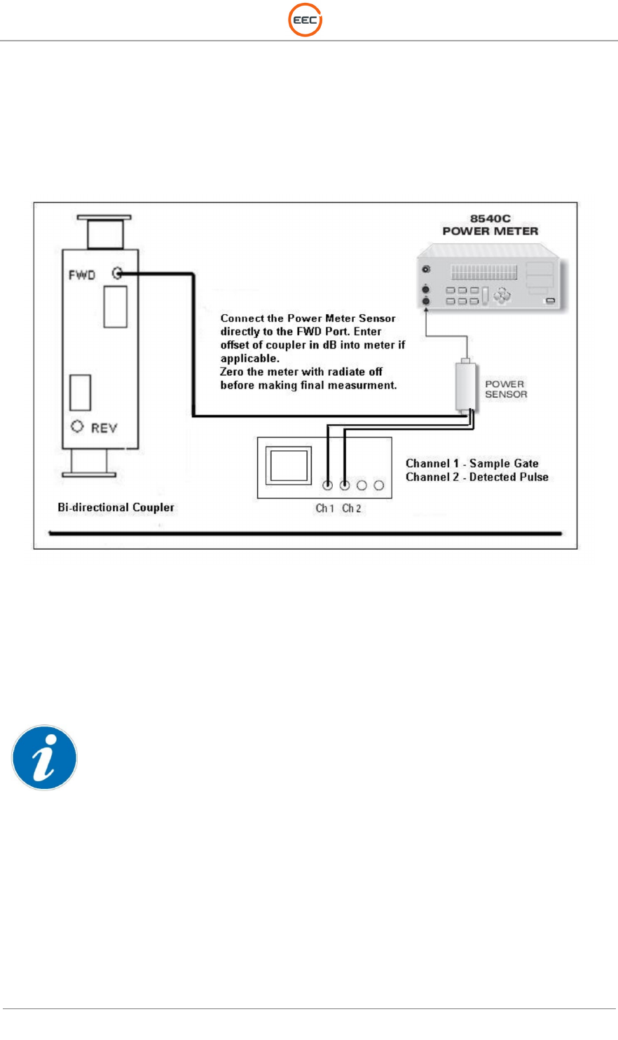
11. Connect the power sensor/detector to the forward port of the bidirectional coupler in the
TX/RX cabinet. Attached the sensors detected pulse and sample pulse to the
oscilloscope per Figure 18.
Figure 18. Test Setup for Peak Power Measurements
12. Zero the power meter. Verify any offsets (if required) and frequency corrections are
applied.
13. Place the radar to RADIATE at full power, measure the detected RF pulse width using the
oscilloscope, and record the results on the test data sheet.
Note: When using the 80351A power meter sensor as the detector the detected pulse will be a positive
going pulse.
14. Connect the oscilloscope (or frequency counter) to the TRIGGER jack and measure the
PRF. Record the PRF value on the data sheet provided.
15. If using an average power meter compute and record the “radar duty cycle” correction
factor using the formula shown below, otherwise log the “duty cycle” correction value as
0 and continue to step 15.

T
ECHNICAL
D
OCUMENTATION
P
ROTECTING
P
EOPLE AND
A
SSETS
®
D
ATE
:
22
M
ARCH
2017
|
V
ERSION
:
1.4
73
R
ANGER
-X5
R
ADAR
S
YSTEM
T
ROUBLESHOOTING
,
M
AINTENANCE
,
AND
C
ALIBRATION
EEC
®
|
C
OMPANY
P
ROPRIETARY
Equation for Duty Cycle Power Correction in dB
When using a Peak Power Meter the Duty Cycle Correction, do not apply the correction to the calculation for
peak power.
16. Using the spectrum analyzer connected to the bidirectional coupler forward port (using
attenuators as required to protect the test equipment), measure and if necessary set, the
RF frequency. Record the frequency for the selected Pulse Width on the test data sheet.
17. De-radiate the system. If not already connected, connect the power meter to the
bidirectional coupler forward port at the transmitter. Zero the power meter. Radiate the
system. Measure and record the power meter measurement.
18. Using the frequency recorded above, find and record the attenuation of the bidirectional
coupler from the calibration chart attached to the FWD port. Compute the peak RF power
from the data recorded above as follows:
Peak power in dB = duty cycle correction factor (if applicable) + coupler attenuation + or the
power meter reading.
For example, assume the following:
Parameter
Measured Value in dB
Notes
Duty Cycle Correction Factor
32.95
See note in step
6
Coupler Attenuation
53.43
See vendor data attached to coupler
Power Meter Reading
-
3.28
Peak Power at TX Coupler
83.1
Sum of columns 1
-
3
Table 7 Peak Power Calculation using Duty Cycle Correction
19. If applicable compute the waveguide line loss and record.
For instance, assume the following:
Parameter
Measured value in dB
Notes
Duty Cycle Correction Factor
32.95
See note in step
6
Couple Attenuation
30.00
See vendor data attached to coupler
Calibrated Attenuator Loss
20.00
See vendor data
Power Meter Reading
-
0.85
Peak Power at Antenna
82.10
Sum of columns 1
-
4
Waveguide Loss
01.00
Power at TX
–
Power at
Antenna
Table 8 Example of Peak Power Calculation
20. Repeat steps 4 thru 18 for the remaining three pulse widths.
21. Record the test results in the Peak Power Test Results – Table 9.
PRFxPW
1
log10

T
ECHNICAL
D
OCUMENTATION
P
ROTECTING
P
EOPLE AND
A
SSETS
®
D
ATE
:
22
M
ARCH
2017
|
V
ERSION
:
1.4
74
R
ANGER
-X5
R
ADAR
S
YSTEM
T
ROUBLESHOOTING
,
M
AINTENANCE
,
AND
C
ALIBRATION
EEC
®
|
C
OMPANY
P
ROPRIETARY
PW0 2
µs
(standard pulse, no pulse compression applied)
Test Parameter
Data
Limit
PW at Transmitter 2.0 ± 10%
PRF 3000 ± 1 Hz
Duty cycle correction
N/A
RF frequency
9500 MHz
Power meter reading
Reference Only (dB)
Coupler attenuation
See vendor data (dB)
Peak RF power
≥ 500 Watts
Peak RF power at antenna Horizontal
coupler
N/A
RF line
loss to Horizontal Coupler (H LDR Mode)
N/A
Peak RF power at antenna Vertical coupler
N/A
RF line loss to Vertical
Coupler
N/A
Table 9. Peak Power Test Results
5.1.2. Transmission / Reception Mode (Horizontal and Vertical) Verification Procedure
1. Apply power to the radar system. Verify or select the following settings.
• Point of Control REMOTE
• Modulator Power On
• Radiate Power - Off
2. Obtain control of the radar system using the EDGE host workstation in the Surveillance
mode of operation.
3. Select the 100 µs pulsewidth mode of operation.
4. Using the EDGE A-scope utility open two A-scope windows. Select the Horizontal
received data in one A-scope window and the vertical received data in the second.
5. With the system still in the radiate or data simulation mode verify ground clutter or
simulated data is observable in each A-scope window.
5.1.3. Operating Range and Range Resolution Verification Procedure
1. Apply power to the radar system. Verify or select the following settings.
• Point of Control REMOTE
• Modulator Power On
• Radiate Power - Off
2. Obtain control of the radar system using the EDGE host workstation in the Surveillance
mode of operation.
3. Set the data range to a value of 45 kilometers.
4. Select a gate width/range resolution of 15.625 meters.
5. Using the EDGE A-scope utility open two A-scope windows. Select the Horizontal
received data in one A-scope window and the vertical received data in the second.
6. With the system still in the radiate mode, verify the presence of ground clutter in each A-
scope window.
7. Change the gate width/range resolution to 31.25 meters.
8. Change the data range value to 100 kilometers.
9. Verify the data resolution and range of the A-scope changes to match the selected gate
resolution.
10. Complete the following table to indicate a range resolution selection of < 50 meters is
available for data acquired up to 100 kilometers.
T
ECHNICAL
D
OCUMENTATION
P
ROTECTING
P
EOPLE AND
A
SSETS
®
D
ATE
:
22
M
ARCH
2017
|
V
ERSION
:
1.4
75
R
ANGER
-X5
R
ADAR
S
YSTEM
T
ROUBLESHOOTING
,
M
AINTENANCE
,
AND
C
ALIBRATION
EEC
®
|
C
OMPANY
P
ROPRIETARY
5.1.4. Unambiguous Velocity and Dual PRF Mode Verification Procedure
1. Apply power to the radar system. Verify or select the following settings.
• Point of Control REMOTE
• Modulator Power On
• Radiate Power - Off
2. Obtain control of the radar system using the EDGE host workstation in the Surveillance
mode of operation.
3. Set the data range to a value of 45 kilometers.
4. Select a gate width/range resolution of 15.625 meters.
5. Open an A-scope window and select the V (velocity) moment for display.
6. Select a pulse width of 2usec at a PRF of 3000.
7. Using the Table 10 as a reference verify the velocity scale changes to match the Nyquist
interval for each mode of operation:
• No-unfolding,
• Unfolding 3:2
• Unfolding 4:3
• Unfolding 5:4.
Velocity Scale and Nyquist Interval
The
wavelength of
9500
MHZ is
0.031557101
meters or
3.155710084
centimeters
The Fold Velocity at
3000
PRF is
23.66782563
meters per second
3:2
4:3
5:4
The Fold Frequency for this input would be
1500
Hertz or
23.7
meters per second
47.3
71
94.7
Table 10. Velocity Scale and Nyquist Interval
5.1.5. Data Output Verification Procedure
1. Apply power to the radar system. Verify or select the following settings.
• Point of Control REMOTE
• Modulator Power On
• Radiate Power - Off
2. Obtain control of the radar system using the EDGE host workstation in the Surveillance
mode of operation.
3. Set the data range to a value of 45 kilometers.
4. Select a gate width/range resolution of 15.625 meters.
5. Open an A-scope window and a real-time data display window.
6. Using the Table 11 as a reference verify that each type of data moment listed can be
selected for display in the A-scope window and the real-time data display window.
Data Moment
Pass / Fail
Uncorrected Reflectivity (UZ)
Pass
Fail
Corrected Reflectivity (Z)
Pass
Fail
Radial Velocity (V)
Pass
Fail
Spectrum Width (W)
Pass
Fail
Differential Reflectivity (ZDR)
Pass
Fail
Differential Phase Shift (PhiDP)
Pass
Fail
Specific Differential Phase (KDP)
Pass
Fail
Polarimetric Correlation Coefficient (RhoHV)
Pass
Fail
Table 11. Data Output Verification

T
ECHNICAL
D
OCUMENTATION
P
ROTECTING
P
EOPLE AND
A
SSETS
®
D
ATE
:
22
M
ARCH
2017
|
V
ERSION
:
1.4
76
R
ANGER
-X5
R
ADAR
S
YSTEM
T
ROUBLESHOOTING
,
M
AINTENANCE
,
AND
C
ALIBRATION
EEC
®
|
C
OMPANY
P
ROPRIETARY
5.2. Transmitter Verification Procedures
5.2.1. Transmitter Control and Indicator Test
These tests verify the operation of the transmitter-receiver controls and indicators.
1. Set point of control to REMOTE. With radar control at the operator workstation, use the
mouse to verify the following functions operate correctly:
• Radar Transmitter Power ON/OFF
• Radiate Mode ON/OFF
• Servo Power ON/OFF
2. It is required that user intervention be required after and emergency system shutdown.
The following steps will demonstrate the procedure enclosure box.
3. Place the system in a normal operating mode.
4. Activate the Emergency Stop switch located on the pedestal.
5. Verify removal of power to the pedestal.
6. Rotate the Emergency Stop switch in the direction of the indicator arrows and verify the
E-Stop return the normal operating position and the restoration of system power after
pressing and holding the E-Reset button for 10 seconds.
7. Verify that the system automatically returns to operation.
Pass
Fail
5.2.2. Transmitter Control Panel Switches and Indicators Test
These tests verify the operation of the transmitter control panel switches and indicators.
1. Using Table 12 as a reference verify each switch and indicator functions as described.
Switch/Indicator
Function
Pass/Fail/NA
Comments
Emergency Stop
De
-
activates pedestal
power immediately
when depressed.
Pass Fail NA
Table 12 Transmitter Control Panel Switches and Indicators Reference Table
T
ECHNICAL
D
OCUMENTATION
P
ROTECTING
P
EOPLE AND
A
SSETS
®
D
ATE
:
22
M
ARCH
2017
|
V
ERSION
:
1.4
77
R
ANGER
-X5
R
ADAR
S
YSTEM
T
ROUBLESHOOTING
,
M
AINTENANCE
,
AND
C
ALIBRATION
EEC
®
|
C
OMPANY
P
ROPRIETARY
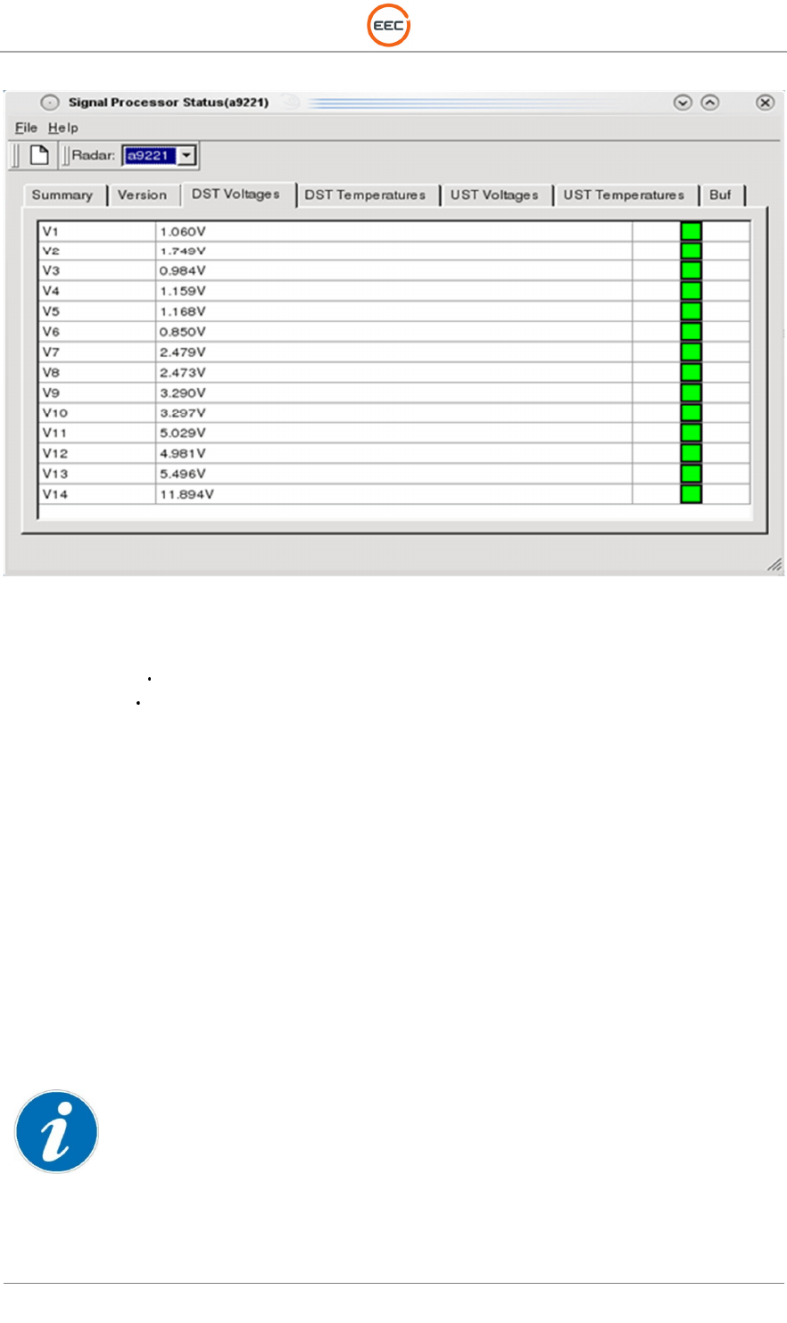
5.2.3. IQ2 Signal Processor Status Tests
1. From EDGE Control Menu open Signal Processor Status Utility.
2. Use Figure 19 to Figure 22 as reference, select the corresponding TAB and verify that
each parameter displayed is shown to be in a GREEN state, which indicates a Pass
condition.
Figure 19 UST Temperature Tab
3. All Temperature indicators are GREEN indicating a Pass condition.
Pass
Fail
T
ECHNICAL
D
OCUMENTATION
P
ROTECTING
P
EOPLE AND
A
SSETS
®
D
ATE
:
22
M
ARCH
2017
|
V
ERSION
:
1.4
78
R
ANGER
-X5
R
ADAR
S
YSTEM
T
ROUBLESHOOTING
,
M
AINTENANCE
,
AND
C
ALIBRATION
EEC
®
|
C
OMPANY
P
ROPRIETARY
Figure 20 UST Voltages Tab
4. All Voltage indicators are GREEN indicating a Pass condition.
Pass
Fail
T
ECHNICAL
D
OCUMENTATION
P
ROTECTING
P
EOPLE AND
A
SSETS
®
D
ATE
:
22
M
ARCH
2017
|
V
ERSION
:
1.4
79
R
ANGER
-X5
R
ADAR
S
YSTEM
T
ROUBLESHOOTING
,
M
AINTENANCE
,
AND
C
ALIBRATION
EEC
®
|
C
OMPANY
P
ROPRIETARY
Figure 21 DST Temperatures Tab
5. All Temperature indicators are GREEN indicating a Pass condition.
Pass
Fail
T
ECHNICAL
D
OCUMENTATION
P
ROTECTING
P
EOPLE AND
A
SSETS
®
D
ATE
:
22
M
ARCH
2017
|
V
ERSION
:
1.4
80
R
ANGER
-X5
R
ADAR
S
YSTEM
T
ROUBLESHOOTING
,
M
AINTENANCE
,
AND
C
ALIBRATION
EEC
®
|
C
OMPANY
P
ROPRIETARY
Figure 22 DST Voltages Tab
6. All Voltage indicators are GREEN indicating a Pass condition.
Pass
Fail
5.3. Antenna / Pedestal Tests
The antenna tests consist of running antenna patterns, measuring the gain, beamwidth, side
lobes and verifying the settings of the upper and lower limit switches. The antenna pedestal must
be level before running the remaining tests.
5.3.1. Elevation Level Verification Test
1. Turn the EL SERVO POWER ON and rotate the antenna for a 0-degree readout
indication.
2. Verify that the elevation level indicates level.
5.3.2. Electrical Limit Switch Test
Before performing test, verify and/or enter Upper and Lower Soft stops settings in the Settings tab on the
LCI.

T
ECHNICAL
D
OCUMENTATION
P
ROTECTING
P
EOPLE AND
A
SSETS
®
D
ATE
:
22
M
ARCH
2017
|
V
ERSION
:
1.4
81
R
ANGER
-X5
R
ADAR
S
YSTEM
T
ROUBLESHOOTING
,
M
AINTENANCE
,
AND
C
ALIBRATION
EEC
®
|
C
OMPANY
P
ROPRIETARY
Summary and Setup:
The electrical limit switches are safety devices installed in the elevation “antenna drive circuit” to
prevent damage to the antenna.
The limit switches remove drive voltage from the elevation motor prior to reaching the lower or
upper mechanical limit stops.
Perform a limit switch alignment prior to this test.
1. Monitor the readout of the antenna elevation position.
2. Slowly drive the antenna up using the manual controls and observe that the drive
movement stops when the antenna reaches an elevation of 90 -0, +1°.
3. Drive the antenna down and observe that the drive stops at approximately -
2.0° + 1° degrees elevation.
4. Turn off the servo drive by activating the pedestal mounted System Safe switch. Manually
move the antenna to the lower hard stop. Record and verify the elevation readout
indicates between -3° to -5°.
5. Manually move the antenna to the upper hard stop. Record and verify the elevation
readout indicates 92° to 96°.
5.3.3. Antenna Speed and Pointing Accuracy Test
1. Set point of control to REMOTE.
2. Using the Edge host computer open a shell terminal and type ‘rex’. (NOTE: Some systems
require typing ‘rexd’ instead of ‘rex’. If atest fails to run, exit out of rex, return to step 2,
and type ‘rexd’ instead of ‘rex’.)
3. Then type ‘point 0 0’
4. Then type ‘atest’.
5. The system will now enter into an automated mode of testing where the antenna
positioning accuracy and speed will be measure and reported to the user. This test will
produce a “Pass” or “Fail” status as well as the error measured.
6. During the automated the test the antenna elevation will be positioned at a rate of > 5
degrees per /second.
7. Using the table below as reference visually monitor and verify the angle displays on the
EDGE Surveillance displays windows.
8. Allow time for the automatic antenna test utility to complete.
9. Note all test results indicated a PASS.
10. Complete the table below by entering a checkmark for each angle pointing accuracy
verification.
11. Save and Print out the ‘atest’ test results and include as an attachment to the SAT
document.
5.3.4. System Interlock and Safe Switch Test
5.3.4.1. Azimuth Safe Switch Verification Test
The Azimuth safe switch, located at the Pedestal Electrical Panel, is designed to prevent
movement in the Azimuth axis while permitting movement in the elevation axis and allowing
radiate. To verify operation of the Azimuth Safe Switch:
Test Procedure:
1. Perform Pedestal Safe Switch Verification Tests.
2. At the Pedestal Electrical Enclosure, place the Azimuth Safe switch in safe mode. Verify

T
ECHNICAL
D
OCUMENTATION
P
ROTECTING
P
EOPLE AND
A
SSETS
®
D
ATE
:
22
M
ARCH
2017
|
V
ERSION
:
1.4
82
R
ANGER
-X5
R
ADAR
S
YSTEM
T
ROUBLESHOOTING
,
M
AINTENANCE
,
AND
C
ALIBRATION
EEC
®
|
C
OMPANY
P
ROPRIETARY
Antenna will not move in the Azimuth Axis.
3. Place the Azimuth Safe switch to [OPERATE] position.
4. Verify the antenna resumes normal operation in the Azimuth Axis.
5. Has Azimuth Safe Switch operation been verified?
5.3.4.2. Elevation Safe Switch Verification Test
The Elevation safe switch, located on the Pedestal Electrical Panel, is designed to prevent
movement in the Elevation axis while permitting movement in the Azimuth axis and allowing
radiate. To verify operation of the Elevation Safe Switch:
Test Procedure:
1. Perform Pedestal Safe Switch Verification Test.
2. At the Pedestal Electrical Enclosure, place the Elevation Safe switch in safe mode. Verify
Antenna will not move in the Elevation Axis.
3. Place the Elevation Safe switch to [OPERATE] position.
4. Verify the antenna resumes normal operation in the Elevation Axis.
5. Has Elevation Safe Switch operation been verified?
5.3.5. Azimuth Orientation and Sun-Track Verification
Test Setup:
A prerequisite is that the radar must have been grossly oriented by compass or other means, to
within +/- 10 degrees Azimuth, and +/- 3 degrees Elevation for the Sun Track utility to be able to
find the sun's position. If the radar is not already within +/- 10 degrees for correct Azimuth, go to
the "Align to Compass" window under the View drop down menu on the menu bar of this window.
Special Note: If the radar to be oriented is x-band, the orientation process using sun track should
be performed on a clear day, with no clouds to block the rays of the sun. Other radar frequencies
are more tolerant of cloud coverage.
Test Prerequisite:
The radar should be powered up and allowed to warm up for 2 hours to ensure that the receiver
frequency is stable.
1. From the Edge Control - Settings, select Configure Edge.
2. In the Configure window, select Radar - Site Information and ensure that the site
Longitude,
3. Latitude, and Height are correct. When they are correct select Apply and OK to exit the
window.
4. Observe the KDE Tool bar at the bottom of the display and verify that the system time is
accurate to within 5 seconds. If the time needs to be adjusted, right click on the time
display and select "Adjust Date and Time". Set the proper system time and select Apply
and OK to exit the window.
5. From the Edge Control window select Antenna Test.
6. In the Antenna Test window select View - Sun Track to see the Sun Track antenna
orientation window. If this is the first attempt at antenna orientation, select Wide from the
Defaults: drop down list. This will enable a +/- 10 degree search area and a 0.5 degree
search step.
7. Use the mouse to select the Start Icon at the top of the Antenna Test window. At this time,
the Edge program will configure the radar, and begin a rectangular search pattern, plotting
the received signal strength. A dark gray colored block indicates a weak return signal, and
a white colored block indicates a strong return signal. The object of the antenna

T
ECHNICAL
D
OCUMENTATION
P
ROTECTING
P
EOPLE AND
A
SSETS
®
D
ATE
:
22
M
ARCH
2017
|
V
ERSION
:
1.4
83
R
ANGER
-X5
R
ADAR
S
YSTEM
T
ROUBLESHOOTING
,
M
AINTENANCE
,
AND
C
ALIBRATION
EEC
®
|
C
OMPANY
P
ROPRIETARY
orientation procedure is to have the white colored blocks, the strongest returns from the
sun, in the center of the Antenna Test viewing area.
8. The Sun Track process may take a considerable amount of time. The operator can
observe the progress in the percent completed status bar, and also can view the time to
completion in the Time: status indicator at the top of the window.
9. When the Sun Track process is complete, the operator should see a blue circle which
indicates the point of strongest return in the Sun Track viewing area.
10. With the mouse, select "Correct" to administer a system wide Azimuth and Elevation
correction to compensate for the difference between the calculated sun position, and the
radar strongest return position.
11. At the Defaults: drop down list, select Medium and repeat the above steps to more
accurately correct the antenna position. When the search process is complete, select
"Correct" to compensate for the known error.
12. At the Defaults: drop down list, select Narrow and repeat the above steps to more
accurately correct the antenna position. When the search process is complete, select
"Correct" to compensate for the known error.
13. Repeat the process for the Narrow mode until the Peak value is less than the system
orientation specification, usually +/- 0.1 degrees.
14. When the Peak values are within the specification as described in the previous step, the
antenna orientation is complete.
15. Print the resulting image from the Narrow Sun-track plot. Attach the printout.
16. Exit the Antenna Test window.
5.4. Receiver Performance Verification Test
5.4.1. IQ2 Receiver Noise Level Verification
1. Use an external signal generator to insert a signal into the receiver before the LNA.
2. Put the external signal generator in CW mode.
3. Configure the external signal generator so that it produces a -50 dBm CW.
4. Place the system in SIDPOL mode of operation (SIM H/V)
5. Open the A-Scope and adjust the receiver band pass filter for peak signal level on the A-
Scope. Peak the signal level by adjusting the frequency on the signal generator.
6. Turn off the RF output of the signal generator and set to maximum attenuation.
7. In the Surveillance window select pulse width 2.0 and set the noise value and log noise
threshold to 0. Take noise sample by clicking on the Sample icon.
8. Verify the noise value is correct by observing the A-Scope. Examples of Correct Noise,
High Noise and Low Noise A-scope displays are shown in the following image.
5.4.2. IQ2 Receiver Calibration and Dynamic Range Verification
Test Procedure:
When using EDGE, select calibration from EDGE control.
Prior to performing the receiver calibration confirm that all performance parameters, such as
transmitted power, antenna gain, beamwidth, path loss, etc…have been entered into the EDGE
configuration GUI.
1. Prior to performing the Dynamic range verification verify or perform a point CAL for each
pulse width as follows:
2. Select the external generator as the source and point as the mode.
3. Set the range to 20KM and the Signal Level to –50.
4. With the pulse width set to 2 usec, verify the frequency is still peaked by observing the A-
scope display. The –50 dBm signal should be clearly visible. Re-peak the frequency of
the generator if necessary.

T
ECHNICAL
D
OCUMENTATION
P
ROTECTING
P
EOPLE AND
A
SSETS
®
D
ATE
:
22
M
ARCH
2017
|
V
ERSION
:
1.4
84
R
ANGER
-X5
R
ADAR
S
YSTEM
T
ROUBLESHOOTING
,
M
AINTENANCE
,
AND
C
ALIBRATION
EEC
®
|
C
OMPANY
P
ROPRIETARY
5. Depress the calibrate button.
6. If the returned value and the expected values are different use the mouse to highlight the
difference in the table then depress the correct button.
7. Depress the run button once again.
8. Repeat steps 2 through 7 for the remaining pulse widths.
9. Using the calibration window, select Range from the calibration window. Enter Range
20km. Click ‘Calibrate’ to start the test.
10. Follow the on screen prompts to set the signal levels.
11. At the completion of the Calibration Save and Print the image.
12. Attached the hardcopy image to the Test Procedure. An example of a typical calibration
result is shown in Figure 15. The green markers on the receiver response curve indicate
the calculated (expected value) and the actual returned value are within the specified
range.
13. Complete Table 13 using the Calibration graph documents produced by the Calibration
utility by entering the final calibration corrections factors and the measured linear dynamic
range.
14. Verify that the calibrated zcal value is automatically or manually updated in the EDGE
configuration file config.rex or using the EDGE configuration miscellaneous interface.
15. After completing the calibration and dynamic range verification utilize the EDGE
calibration utility to calculate the signal level required to simulate a weather target with a
reflectivity value of 13.5 dBz at the range selected for calibration (typically 20km). The
mode of operation should be set to 2usec with a bandwidth of 0.5 MHZ prior to performing
the calculation.
16. Use the calibrated signal generator to inject the signal level taken from the calibration
chart for 13.5 dBz (~0.3mm/hr). Pulse mode is recommended with the pulse centered on
the same range as used for calibration (typically 20 KM)
17. Slowly adjust the signal level and verify that when the power level needed to simulate
13.5 dBz of signal is reached that the signal is still easily detectable on the ascope display.
18. Change the ascope display to the rain rate mode and verify that a signal level of 0.3mm/hr
is also easily observed at the same range.
19. Repeat the sensitivity test for the vertical channel using the same pulsewidth selection
(2usec/BW 0.5MHZ).
20. Log the sensitivity test results in Table 13.
Pulsewidth (µs)
Measured Dynamic Range (dB)
Calibration Correction Factor
(dBz0/ZCal)
H(Horizontal)
V (Vertical)
H(Horizontal)
V (Vertical)
2.0
20.0
50.0
100.0
Noise
Figure Data from LNA
Datasheet (dB)
≤ 2.5 dB
≤ 2.5 dB
Hard Copies
of
Calibration
Verification are Attached
Yes
No
Yes
No
13.5 dBz sensitivity Achieved
Yes
No
Yes
No
0.3 mm/hr. sensitivity
achieved
Yes
No
Yes
No
Table 13. Receiver Noise Figure and Dynamic Range Test Results
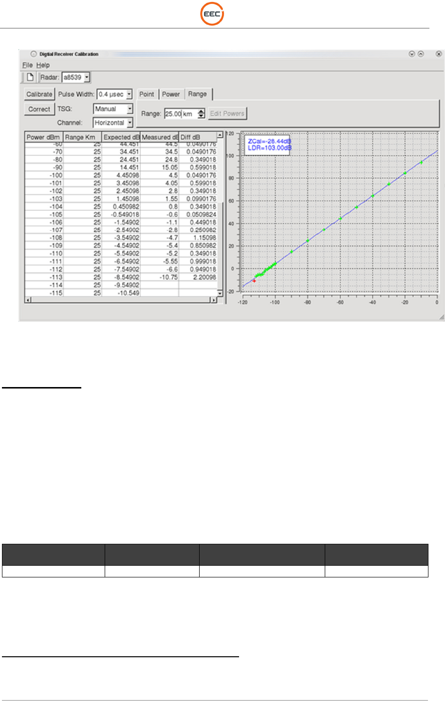
T
ECHNICAL
D
OCUMENTATION
P
ROTECTING
P
EOPLE AND
A
SSETS
®
D
ATE
:
22
M
ARCH
2017
|
V
ERSION
:
1.4
85
R
ANGER
-X5
R
ADAR
S
YSTEM
T
ROUBLESHOOTING
,
M
AINTENANCE
,
AND
C
ALIBRATION
EEC
®
|
C
OMPANY
P
ROPRIETARY
Figure 23. Typical Calibration Test Results Screenshot (LDR > 100dB)
5.4.3. Minimum Discernable Signal (MDS) Measurement and Verification Test
Test Preparation
1. Use an external signal generator to insert a signal into the receiver before the LNA.
2. Put the external signal generator in pulse mode synchronizing to the radar trigger.
3. Configure the external signal generator so that it produces a 10 km wide pulse (65 µs)
centered at 15 km (trigger delay of approximately 100 µs).
4. Open A-Scope display modes. Select unfiltered intensity, no clutter-filtering mode.
5. From Edge surveillance select range normalization ON and 30 km range. Set Gate Width
to 15.625 meters and the sample size to 32 pulses.
6. Be sure to take a new noise sample with no signal injected after selecting the pulsewidth
to be verified.
7. Inject the following signal levels shown in the Signal Strength column for each pulse width.
Verify for both the Horizontal and Vertical Receiver channels.
Pulse Width
Signal Strength
Pulse Discernible
Horizontal
Pulse Discernible Vertical
PW0 (2.0µs)
-
113
dBm
Pass
Fail
Pass
Fail
5.4.4. Clutter Filter and Clutter Rejection Verification Test
The following test will verify a ground clutter suppression capability of the system to be 40 dB or
greater. TX Correction must be enabled prior to running the clutter suppression test.
Clutter Filter Suppression Verification Procedure:
This will show that the IQ2 is capable of rejecting clutter signals in filters 1 through 15. The CSS
of the IQ2 will be evaluated using a stable signal source such as the Agilent 33250A or equivalent

T
ECHNICAL
D
OCUMENTATION
P
ROTECTING
P
EOPLE AND
A
SSETS
®
D
ATE
:
22
M
ARCH
2017
|
V
ERSION
:
1.4
86
R
ANGER
-X5
R
ADAR
S
YSTEM
T
ROUBLESHOOTING
,
M
AINTENANCE
,
AND
C
ALIBRATION
EEC
®
|
C
OMPANY
P
ROPRIETARY
signal source. This signal will be injected into the IQ2 receiver using coaxial cables. The IQ2 will
be configured in such a manner that the level of the injected CW signal, which is clutter, will be
reduced by 40 dB.
Test Preparation:
1. Using the Agilent 33250A or equivalent signal source and an IF splitter inject a CW signal
at 60MHZ into both the burst input and the horizontal input of the IQ2. A typical starting
level for the injected signal is 500millivolts P-P.
2. Open an A-scope windows and select the CCOR H data moment for display.
3. Select an operational mode of 2.0uSec at 60 KM range using the Surveillance control
screen.
4. Set the sample size to 240 pulses to ensure accurate readings.
5. Set the A-scope cursor to a range of 30 KM.
6. Open the burst alignment utility and initiate a burst sample.
7. Adjust the signal level input until a burst level of at least +/-25,000 units is displayed in
the burst sample window.
8. Set the Clutter Correction Threshold to 70 dB for the selected pulse width.
Test Procedure:
1. Select Clutter Filter (50db)
2. Apply clutter filter number 1.
3. Visual observe a clutter rejection of at least 40 dB in the CCOR A-scope display.
4. Repeat the verification procedure for all available clutter filters.
5. Verify a CCOR moment data value of at least 40 dB for all selected filters.
Pass
Fail