Enterprise Electronics RANGERX5 Ranger-X5 RADAR User Manual Section 2 Troubleshooting Maintenance Calibration v1 4 DRAFT 002
Enterprise Electronics Corporation Ranger-X5 RADAR Section 2 Troubleshooting Maintenance Calibration v1 4 DRAFT 002
Contents
- 1. User Manual Troubleshooting Maintenance Calibration Part 1
- 2. User Manual Troubleshooting Maintenance Calibration Part 2
- 3. User Manual Overview Theory Part 2
- 4. User Manual Overview Theory Part 1
- 5. User Manual Overview Theory Part 3
- 6. User Manual Overview Theory Part 4
User Manual Troubleshooting Maintenance Calibration Part 2
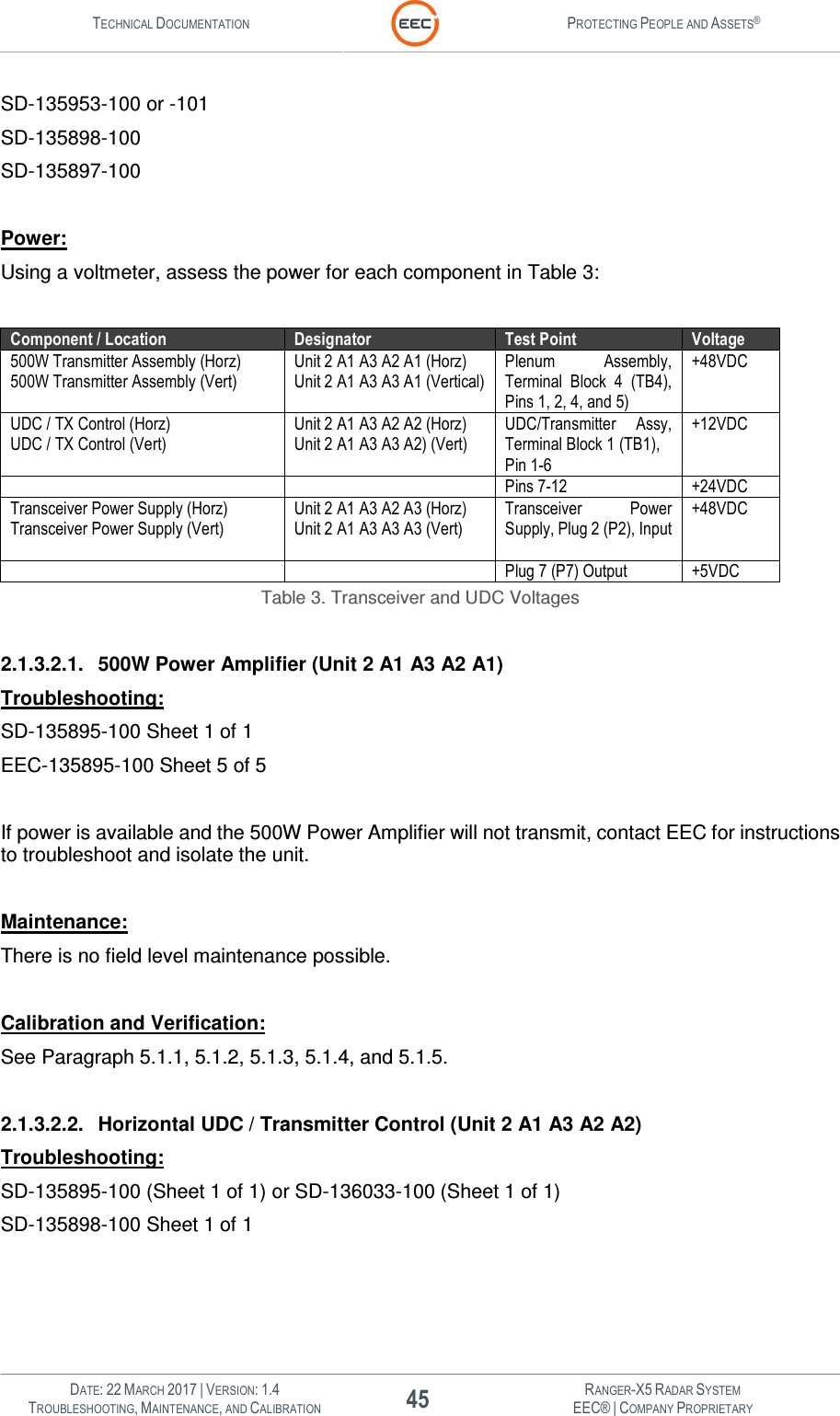
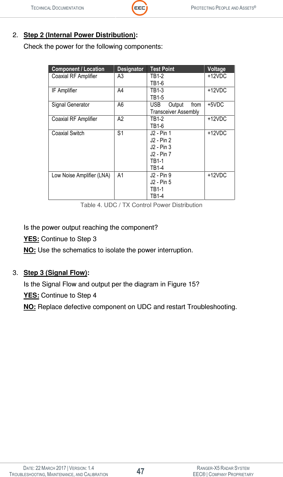
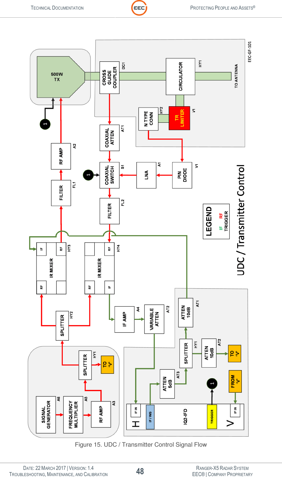
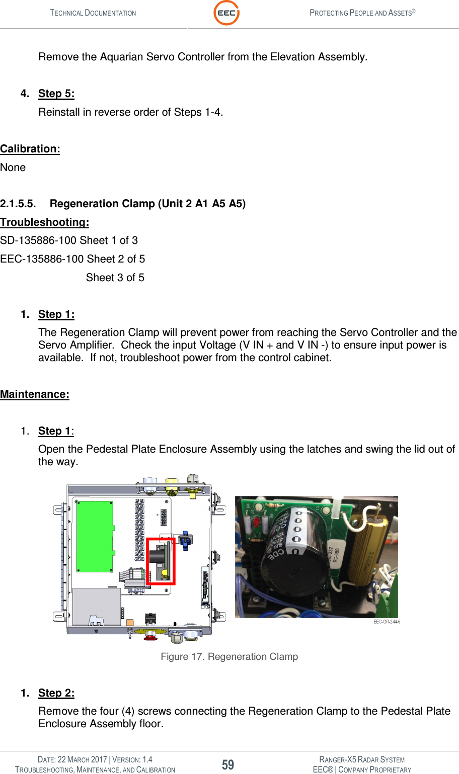


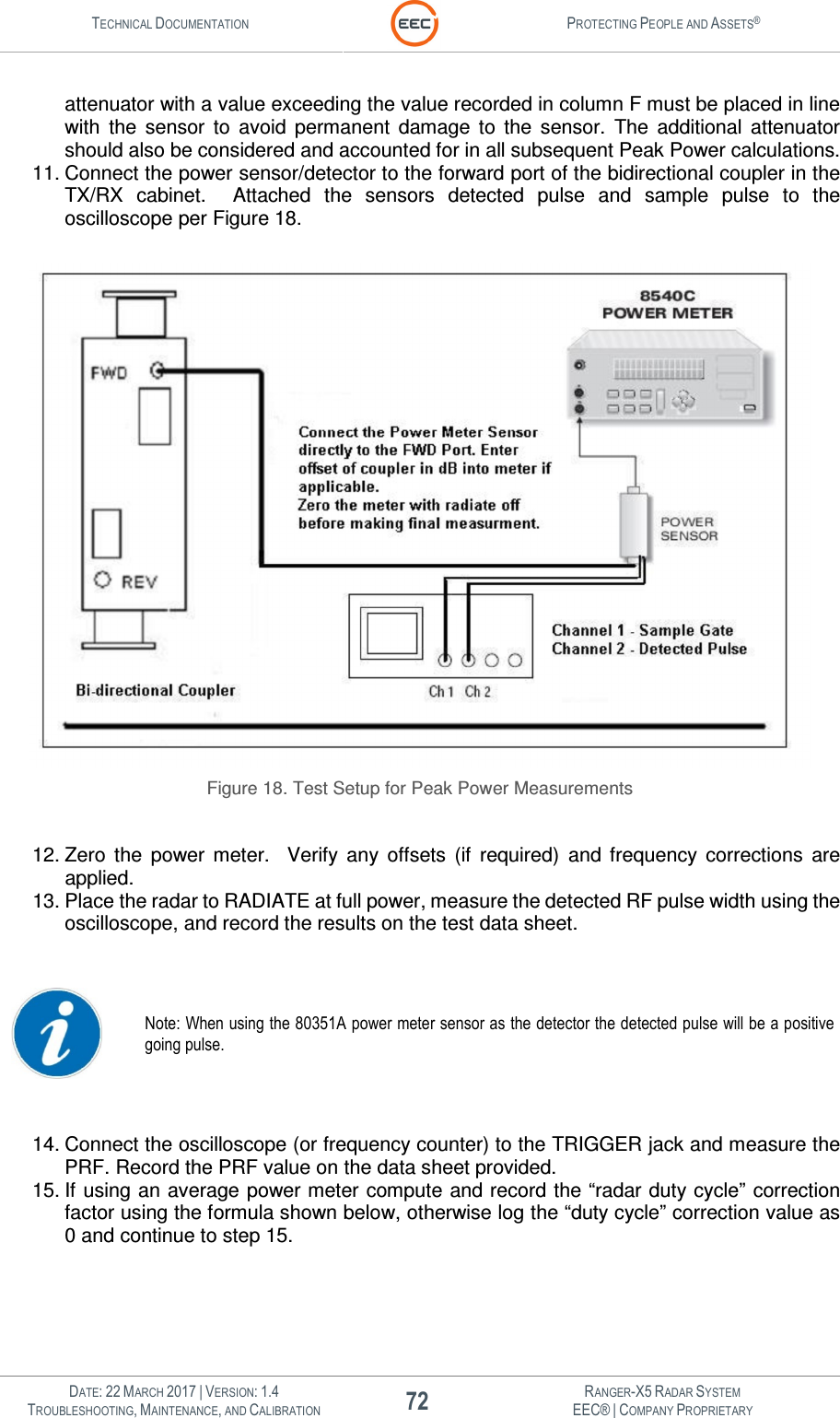
![TECHNICAL DOCUMENTATION PROTECTING PEOPLE AND ASSETS® DATE: 22 MARCH 2017 | VERSION: 1.4 82 RANGER-X5 RADAR SYSTEM TROUBLESHOOTING, MAINTENANCE, AND CALIBRATION EEC® | COMPANY PROPRIETARY Antenna will not move in the Azimuth Axis. 3. Place the Azimuth Safe switch to [OPERATE] position. 4. Verify the antenna resumes normal operation in the Azimuth Axis. 5. Has Azimuth Safe Switch operation been verified? 5.3.4.2. Elevation Safe Switch Verification Test The Elevation safe switch, located on the Pedestal Electrical Panel, is designed to prevent movement in the Elevation axis while permitting movement in the Azimuth axis and allowing radiate. To verify operation of the Elevation Safe Switch: Test Procedure: 1. Perform Pedestal Safe Switch Verification Test. 2. At the Pedestal Electrical Enclosure, place the Elevation Safe switch in safe mode. Verify Antenna will not move in the Elevation Axis. 3. Place the Elevation Safe switch to [OPERATE] position. 4. Verify the antenna resumes normal operation in the Elevation Axis. 5. Has Elevation Safe Switch operation been verified? 5.3.5. Azimuth Orientation and Sun-Track Verification Test Setup: A prerequisite is that the radar must have been grossly oriented by compass or other means, to within +/- 10 degrees Azimuth, and +/- 3 degrees Elevation for the Sun Track utility to be able to find the sun's position. If the radar is not already within +/- 10 degrees for correct Azimuth, go to the "Align to Compass" window under the View drop down menu on the menu bar of this window. Special Note: If the radar to be oriented is x-band, the orientation process using sun track should be performed on a clear day, with no clouds to block the rays of the sun. Other radar frequencies are more tolerant of cloud coverage. Test Prerequisite: The radar should be powered up and allowed to warm up for 2 hours to ensure that the receiver frequency is stable. 1. From the Edge Control - Settings, select Configure Edge. 2. In the Configure window, select Radar - Site Information and ensure that the site Longitude, 3. Latitude, and Height are correct. When they are correct select Apply and OK to exit the window. 4. Observe the KDE Tool bar at the bottom of the display and verify that the system time is accurate to within 5 seconds. If the time needs to be adjusted, right click on the time display and select "Adjust Date and Time". Set the proper system time and select Apply and OK to exit the window. 5. From the Edge Control window select Antenna Test. 6. In the Antenna Test window select View - Sun Track to see the Sun Track antenna orientation window. If this is the first attempt at antenna orientation, select Wide from the Defaults: drop down list. This will enable a +/- 10 degree search area and a 0.5 degree search step. 7. Use the mouse to select the Start Icon at the top of the Antenna Test window. At this time, the Edge program will configure the radar, and begin a rectangular search pattern, plotting the received signal strength. A dark gray colored block indicates a weak return signal, and a white colored block indicates a strong return signal. The object of the antenna](https://usermanual.wiki/Enterprise-Electronics/RANGERX5.User-Manual-Troubleshooting-Maintenance-Calibration-Part-2/User-Guide-3348735-Page-42.png)