Enterprise Electronics RANGERX5 Ranger-X5 RADAR User Manual Overview Theory Part 4
Enterprise Electronics Corporation Ranger-X5 RADAR Overview Theory Part 4
Contents
User Manual Overview Theory Part 4
T
ECHNICAL
D
OCUMENTATION
P
ROTECTING
P
EOPLE AND
A
SSETS
®
D
ATE
:
27
M
ARCH
2017
|
V
ERSION
:
1.8
61
R
ANGER
®
-
X5
R
ADAR
S
YSTEM
(M
OBILE
)
F
UNCTIONAL
O
VERVIEW AND
T
HEORY OF
O
PERATION
EEC
®
|
C
OMPANY
P
ROPRIETARY
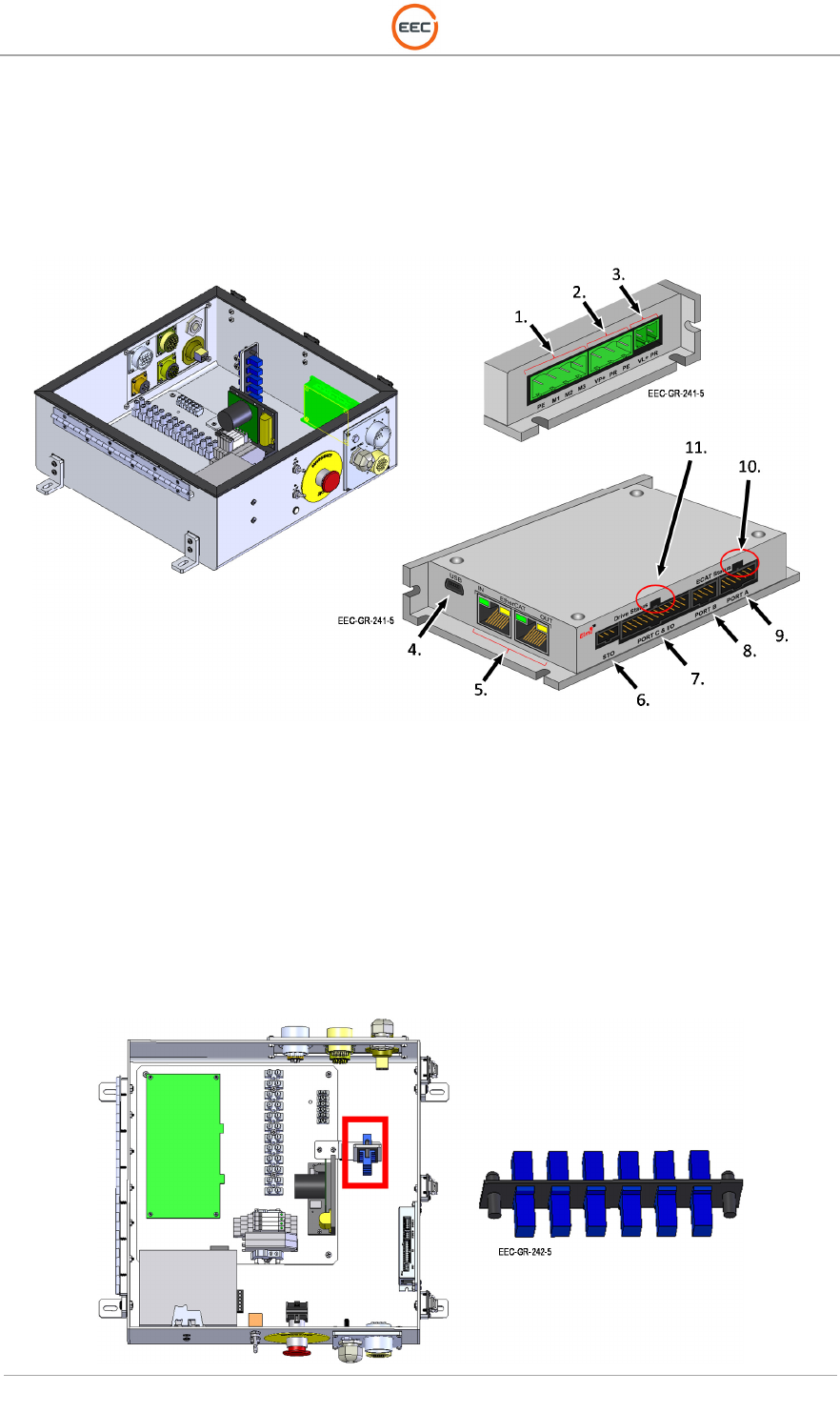
2.1.6.2. Servo Amplifier, 100V, 10A (Unit 2 A1 A5 A2)
The Servo Amplifier is a digital servo amplifier providing advanced position control for the Ranger-
X5 Antenna System. The servo amplifier works in conjunction with the Aquarian Servo Controller
to ensure the pointing accuracy of the pedestal system.
Figure 57. Servo Amplifier (135914-100)
See Paragraph 0 for more details
2.1.6.3. Fiber Optic Coupler (Unit 2 A1 A5 A3)
This unit is functionally identical to the Fiber Optic Coupler in the Control Cabinet. See Paragraph
1.1.7 for details.
T
ECHNICAL
D
OCUMENTATION
P
ROTECTING
P
EOPLE AND
A
SSETS
®
D
ATE
:
27
M
ARCH
2017
|
V
ERSION
:
1.8
62
R
ANGER
®
-
X5
R
ADAR
S
YSTEM
(M
OBILE
)
F
UNCTIONAL
O
VERVIEW AND
T
HEORY OF
O
PERATION
EEC
®
|
C
OMPANY
P
ROPRIETARY
Figure 58. Fiber Optic Coupler (FSP-SC-BR)
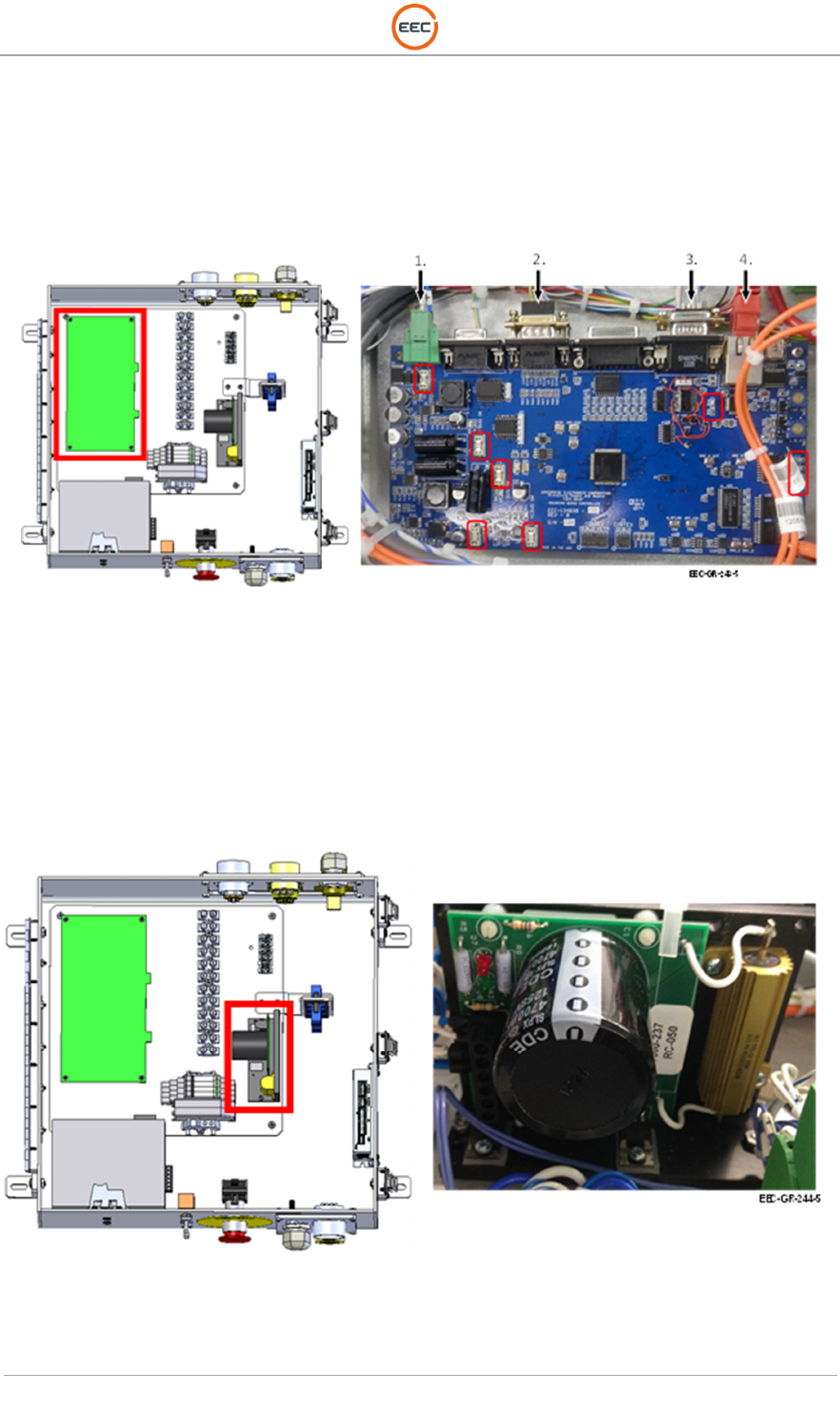
2.1.6.4. Aquarian Servo Controller PCA (Unit 2 A1 A5 A4)
This unit is functionally identical to the Elevation Servo Controller. See Paragraph 0 for details.
Figure 59. Aquarian Servo Controller (134839-103)
2.1.6.5. Regeneration Clamp (Unit 2 A1 A5 A5)
This unit is functionally identical to the Regeneration Clamp in the Elevation Assembly. See
Paragraph 0 for details.
Figure 60. Regeneration Clamp (1000-237)
T
ECHNICAL
D
OCUMENTATION
P
ROTECTING
P
EOPLE AND
A
SSETS
®
D
ATE
:
27
M
ARCH
2017
|
V
ERSION
:
1.8
63
R
ANGER
®
-
X5
R
ADAR
S
YSTEM
(M
OBILE
)
F
UNCTIONAL
O
VERVIEW AND
T
HEORY OF
O
PERATION
EEC
®
|
C
OMPANY
P
ROPRIETARY
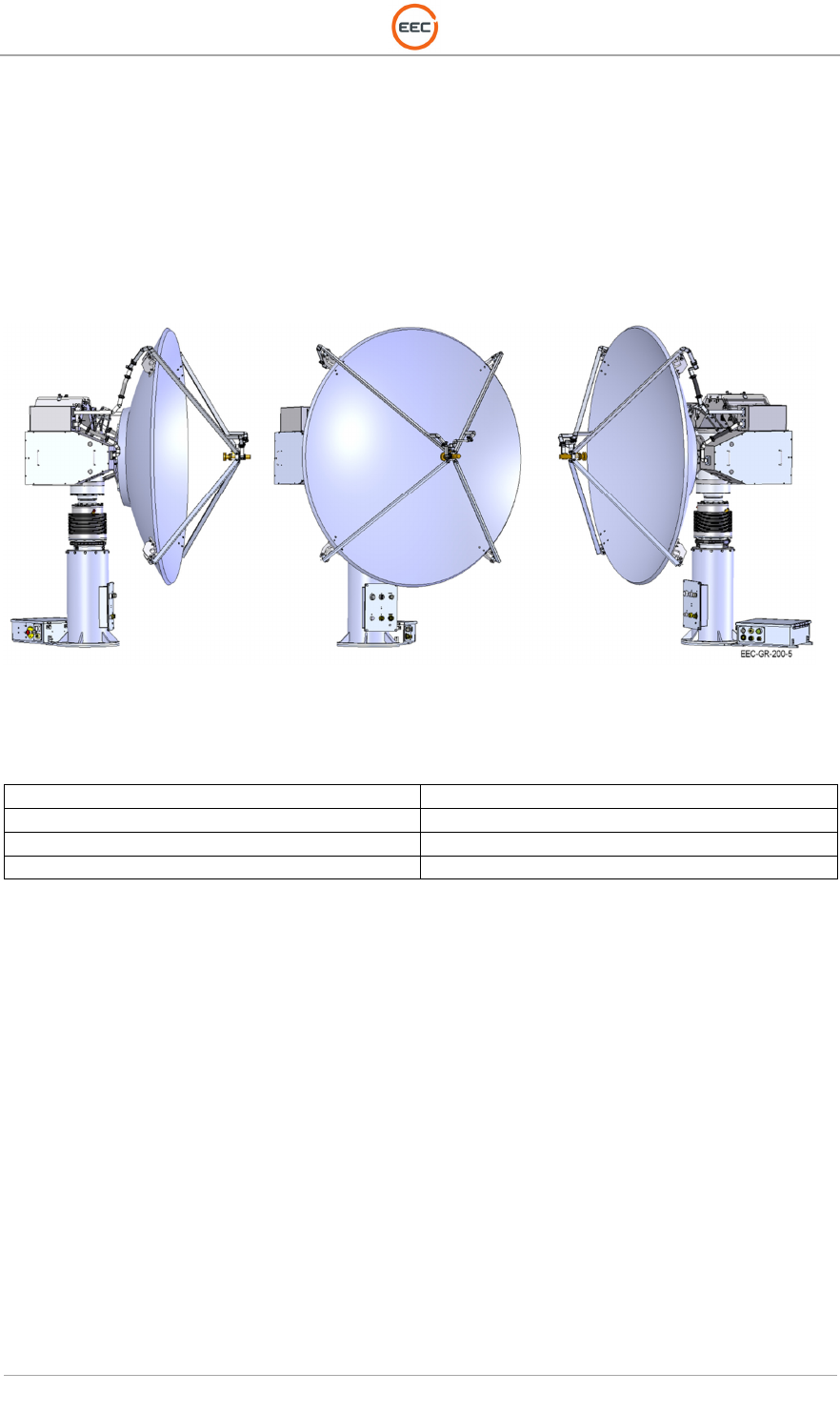
2.2. Antenna Assembly – 1 Meter Reflector (Unit 2 A2)
The 1.8-Meter Antenna / Feed Horn Assembly is specifically designed and built for the Ranger
Series radar system. The unit is a lightweight, composite material. The feed horn is tuned to the
reflector and mounted for optimal dual polarization performance.
Figure 61. 1.8 Meter Antenna
Antenna Size Antenna Gain
1 Meter / 3.2 Feet 36.0 ± 0.5 dBi
1.8 Meter / 6 Feet 42.0 ± 0.5 dBi
2.4 Meter / 8 Feet 44.5 ± 0.5 dBi

T
ECHNICAL
D
OCUMENTATION
P
ROTECTING
P
EOPLE AND
A
SSETS
®
D
ATE
:
27
M
ARCH
2017
|
V
ERSION
:
1.8
64
R
ANGER
®
-
X5
R
ADAR
S
YSTEM
(M
OBILE
)
F
UNCTIONAL
O
VERVIEW AND
T
HEORY OF
O
PERATION
EEC
®
|
C
OMPANY
P
ROPRIETARY

T
ECHNICAL
D
OCUMENTATION
P
ROTECTING
P
EOPLE AND
A
SSETS
®
D
ATE
:
27
M
ARCH
2017
|
V
ERSION
:
1.8
65
R
ANGER
®
-
X5
R
ADAR
S
YSTEM
(M
OBILE
)
F
UNCTIONAL
O
VERVIEW AND
T
HEORY OF
O
PERATION
EEC
®
|
C
OMPANY
P
ROPRIETARY
C
HAPTER
3
R
ADOME

T
ECHNICAL
D
OCUMENTATION
P
ROTECTING
P
EOPLE AND
A
SSETS
®
D
ATE
:
27
M
ARCH
2017
|
V
ERSION
:
1.8
66
R
ANGER
®
-
X5
R
ADAR
S
YSTEM
(M
OBILE
)
F
UNCTIONAL
O
VERVIEW AND
T
HEORY OF
O
PERATION
EEC
®
|
C
OMPANY
P
ROPRIETARY
This page intentionally blank.

T
ECHNICAL
D
OCUMENTATION
P
ROTECTING
P
EOPLE AND
A
SSETS
®
D
ATE
:
27
M
ARCH
2017
|
V
ERSION
:
1.8
67
R
ANGER
®
-
X5
R
ADAR
S
YSTEM
(M
OBILE
)
F
UNCTIONAL
O
VERVIEW AND
T
HEORY OF
O
PERATION
EEC
®
|
C
OMPANY
P
ROPRIETARY
3. Radome (Unit 3)
A separate (OPTIONAL) Protective Radome technical description is included as an attachment,
if provided by EEC.

T
ECHNICAL
D
OCUMENTATION
P
ROTECTING
P
EOPLE AND
A
SSETS
®
D
ATE
:
27
M
ARCH
2017
|
V
ERSION
:
1.8
68
R
ANGER
®
-
X5
R
ADAR
S
YSTEM
(M
OBILE
)
F
UNCTIONAL
O
VERVIEW AND
T
HEORY OF
O
PERATION
EEC
®
|
C
OMPANY
P
ROPRIETARY
This page intentionally blank.

T
ECHNICAL
D
OCUMENTATION
P
ROTECTING
P
EOPLE AND
A
SSETS
®
D
ATE
:
27
M
ARCH
2017
|
V
ERSION
:
1.8
69
R
ANGER
®
-
X5
R
ADAR
S
YSTEM
(M
OBILE
)
F
UNCTIONAL
O
VERVIEW AND
T
HEORY OF
O
PERATION
EEC
®
|
C
OMPANY
P
ROPRIETARY
C
HAPTER
4
S
YSTEM
T
HEORY OF
O
PERATIONS

T
ECHNICAL
D
OCUMENTATION
P
ROTECTING
P
EOPLE AND
A
SSETS
®
D
ATE
:
27
M
ARCH
2017
|
V
ERSION
:
1.8
70
R
ANGER
®
-
X5
R
ADAR
S
YSTEM
(M
OBILE
)
F
UNCTIONAL
O
VERVIEW AND
T
HEORY OF
O
PERATION
EEC
®
|
C
OMPANY
P
ROPRIETARY
This page intentionally blank.

T
ECHNICAL
D
OCUMENTATION
P
ROTECTING
P
EOPLE AND
A
SSETS
®
D
ATE
:
27
M
ARCH
2017
|
V
ERSION
:
1.8
71
R
ANGER
®
-
X5
R
ADAR
S
YSTEM
(M
OBILE
)
F
UNCTIONAL
O
VERVIEW AND
T
HEORY OF
O
PERATION
EEC
®
|
C
OMPANY
P
ROPRIETARY
4. System Theory of Operations
The following sections describe the system theory of operations. System theory is used to
describe software controls, signal flow and the relationships of sub-assemblies. System theory is
divided into the following categories:
1. COBRA Software
2. Primary Power Supply and Distribution
3. Interlock Circuitry
4. Transmitter Control and Transmit
5. Transmit Waveguide and Star Waveguide Assembly
6. Receiver Signal Flow
7. Antenna Control and Angle Acquisition
8. Communication Interface
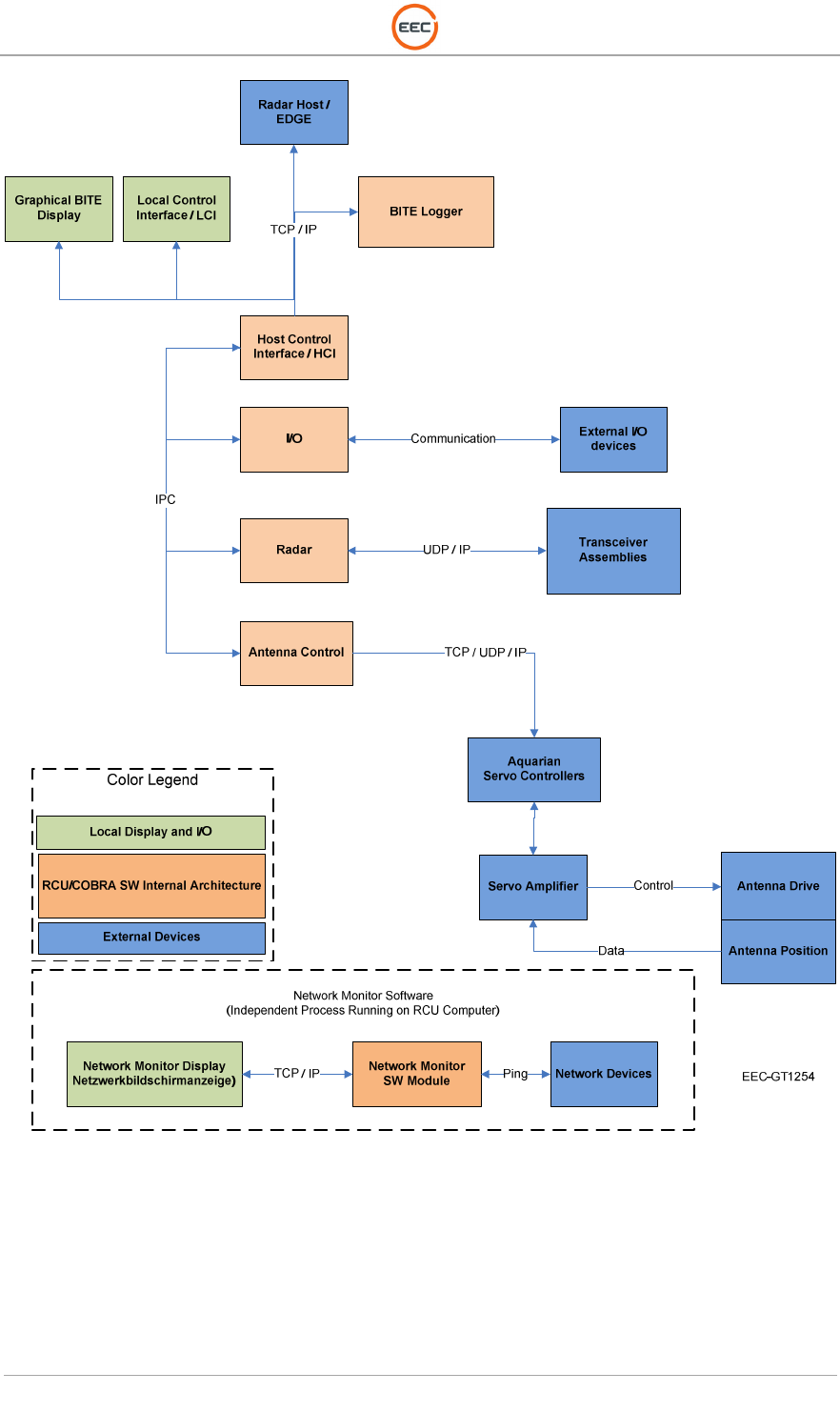
4.1. COBRA Software
The Ranger-X5 local user station operates through the EDGE Software through an interface to
the COBRA application software and the Local Control Interface (LCI). COBRA processes all
operator commands from either the local or remote operator EDGE workstations and routes them
to the appropriate radar control circuits. The I/O modules collect information on radar
performance and status, and provide basic, bit level control to specific subsystems. The COBRA
program also correlates and processes information and procedures from the BITE sub-system,
controls the Antenna/Pedestal operational parameters, and performs basic radar control
functions. The Aquarian Servo Controller, the UDC / Transmit Control Unit, and the COBRA
software seamlessly integrate with the IQ2-IFD and IQ2-DSP, communicating by standard
Ethernet protocol.
The EDGE workstation(s) input the commands and pass system status signals to and from the
system units such as the transmitter/receiver system and the Antenna system. In LOCAL mode,
manual inputs for Antenna drive commands come from the EDGE operator control. The EDGE
Software and the COBRA software can display all radar BITE data on the KVM screen. The
COBRA software also sends the BITE data to the EDGE remote host processor.
The interface, internally and to external workstations and processors, is a 10/100/1000 Ethernet
data communications circuit. See Figure 62 for a graphical depiction of the COBRA software
Architecture and communications protocols with other radar units.
T
ECHNICAL
D
OCUMENTATION
P
ROTECTING
P
EOPLE AND
A
SSETS
®
D
ATE
:
27
M
ARCH
2017
|
V
ERSION
:
1.8
72
R
ANGER
®
-
X5
R
ADAR
S
YSTEM
(M
OBILE
)
F
UNCTIONAL
O
VERVIEW AND
T
HEORY OF
O
PERATION
EEC
®
|
C
OMPANY
P
ROPRIETARY
Figure 62.Ranger-X5 COBRA Software Architecture
4.1.1. BITE Page
The BITE information from within the RANGER-X5 is processed and routed to the EDGE
software. The BITE information can also display on the COBRA LCI software through the KVM
display. The COBRA LCI BITE Display has tabs to display the log file of command and

T
ECHNICAL
D
OCUMENTATION
P
ROTECTING
P
EOPLE AND
A
SSETS
®
D
ATE
:
27
M
ARCH
2017
|
V
ERSION
:
1.8
73
R
ANGER
®
-
X5
R
ADAR
S
YSTEM
(M
OBILE
)
F
UNCTIONAL
O
VERVIEW AND
T
HEORY OF
O
PERATION
EEC
®
|
C
OMPANY
P
ROPRIETARY
responses; to set the limits for the statuses of the various components; and to configure the layout
of the Transmitter, Pedestal, Signal Processor, and Receiver BITE screens.
The Naming Conventions and Source are as follows:
Abbreviation
Naming Convention and Source
Abbreviation
Naming Convention and Source
mrp
IQ2
mb
Motherboard
ped
Pedestal
mfc
Manuel Frequency Control
rcu
Radar Control Unit
mode
Mode
rx
Receiver
neg
Negative
tx
Transmitter
normal
Normal
5
v
Direct Current Voltage
ntp
Network Time Protocol
1
2
v
Direct Current Voltage
offset
Offset
24v
Direct Current Voltage
online
Online
48v
Direct Current Voltage
over
Over
az
Azimuth
pci
Process Capability Index
blanking
Blanking
performance
Performance
burst
Burst
pos
Positive
cab
Cabinet
present
Present
clock
Clock
press
Press
coax
Coaxcable
proc
Processing
contactor
Contactor
protocol
Protocol
cpu
Central Processing Unit
ps
Power Supply
current
Current
psa12
Power Supply 12
V
detected
Detected
psa15
Power Supply 15V
dma
Direct Memory Access
psa
48
Power Supply
48V
downlink
Downlink
psa5
Power Supply 5V
dsp
Digital Signal Processor
pump
Pump
el
Elevation
purge
Purge
enabled
Enabled
pwr
Power
error
Error
radiate
Radiate
ext
External
ray
Ray
fault
Fault
relay
Relay
fifo
First In First Out
reverse
Reverse
filament
Filament
safe
Safe
fo
Fiber Optic
safety
Safety
forward
Forward
sample
Sample
fpga
Field
Programmable Gate
-
Array
servo
Servo
free space
Free Space
speed
Speed
freq
Frequency
Stalo
Stalo
hd
Hard Disk
standby
Standby
hh
Horizontal High
start
Start
hl
Horizontal Low
step
Step
hold
Hold
switch
Switch
home
Home
sys
System
hotbox
Description of the Klystron Enclosure
sw
Switch
humidity
Humidity
temp
Temperature
hw
Hardware
timeout
Timeout
i
Current
tp
Throughput
ifd
Intermediate Frequency Digitizer
trigger
Trigger
igbt
Insulated Gate Bipolar Transistor
uplink
Uplink
initialized
Initialized
v
Velocity
int
Internal
velocity
Velocity
interlock
Interlock
vh
Vertical High
lock
Lock
vl
Vertical Low
lube
Lube
vswr
Voltage Standing Wave Ratio
SSPA
Solid State Power Amplifier
main
Main
Table 2. BITE Display Naming Convention
T
ECHNICAL
D
OCUMENTATION
P
ROTECTING
P
EOPLE AND
A
SSETS
®
D
ATE
:
27
M
ARCH
2017
|
V
ERSION
:
1.8
74
R
ANGER
®
-
X5
R
ADAR
S
YSTEM
(M
OBILE
)
F
UNCTIONAL
O
VERVIEW AND
T
HEORY OF
O
PERATION
EEC
®
|
C
OMPANY
P
ROPRIETARY
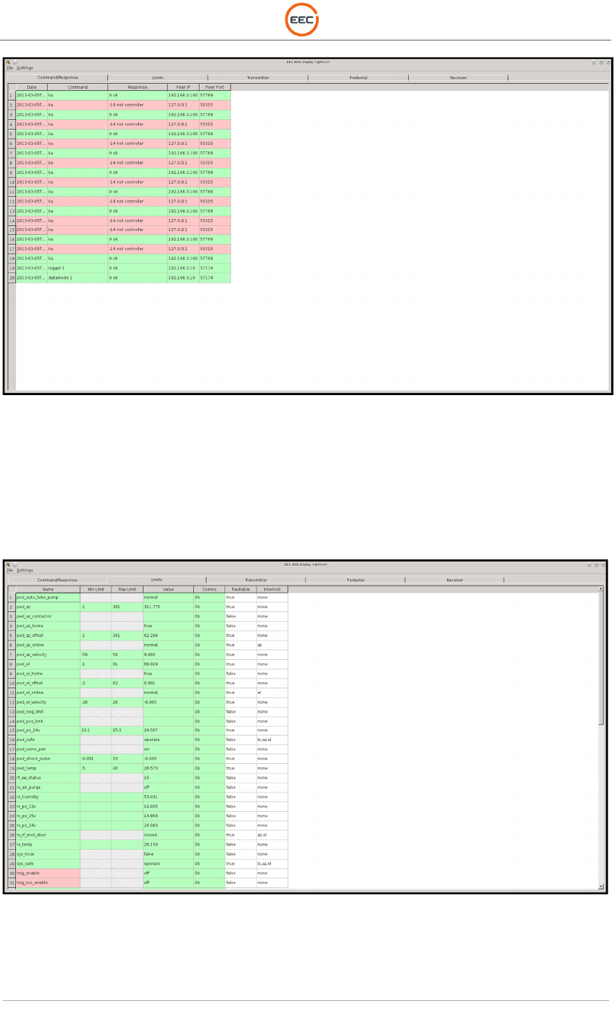
Figure 63. BITE Command / Response Display
Figure 63
contains the command/response display. There is a display of command sent to the
COBRA in sequential order along with the response from COBRA and information about where
the command came from. Commands with a successful response have a green background;
commands resulting in an error have a red background. The most recent 1000
command/response pairs are available in this screen.
Figure 64. BITE Commands and Function with Associated Limits
The BITE Command Functions and Limits screen (see
Figure 64
) displays the BITE limits and
allows the user to modify the limits. For example, if the BITE is monitoring a 15 V power supply,
the limits may be set to 14.5 and 15.5 volts, meaning anything out of this range will be indicated
T
ECHNICAL
D
OCUMENTATION
P
ROTECTING
P
EOPLE AND
A
SSETS
®
D
ATE
:
27
M
ARCH
2017
|
V
ERSION
:
1.8
75
R
ANGER
®
-
X5
R
ADAR
S
YSTEM
(M
OBILE
)
F
UNCTIONAL
O
VERVIEW AND
T
HEORY OF
O
PERATION
EEC
®
|
C
OMPANY
P
ROPRIETARY
as an error. If no upper limit is supplied, then anything above the lower limit is considered good.
Conversely, if no lower limit is provided, then anything below the upper limit is considered good.
If there are no limits, the item is for informational purposes only.
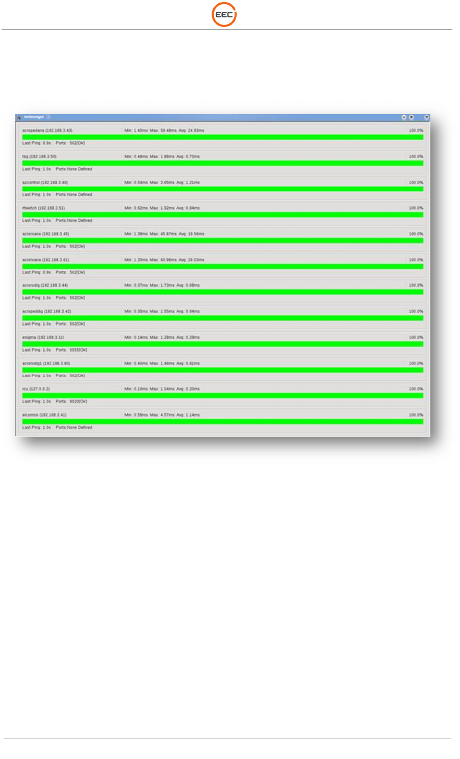
The Network Monitor displays the interaction between the communication devices.
Figure 65. Network Monitor Screen

T
ECHNICAL
D
OCUMENTATION
P
ROTECTING
P
EOPLE AND
A
SSETS
®
D
ATE
:
27
M
ARCH
2017
|
V
ERSION
:
1.8
76
R
ANGER
®
-
X5
R
ADAR
S
YSTEM
(M
OBILE
)
F
UNCTIONAL
O
VERVIEW AND
T
HEORY OF
O
PERATION
EEC
®
|
C
OMPANY
P
ROPRIETARY
4.2. Primary Power Supply and Distribution
Primary power for the Ranger-X5 is a single-phase 120/208 VAC input from the sites Main input.
The end user is required to provide an external UPS and a service disconnect with an Emergency
Stop button to remove all power from the radar system and provide a Lock-out/Tag-out point for
maintenance.
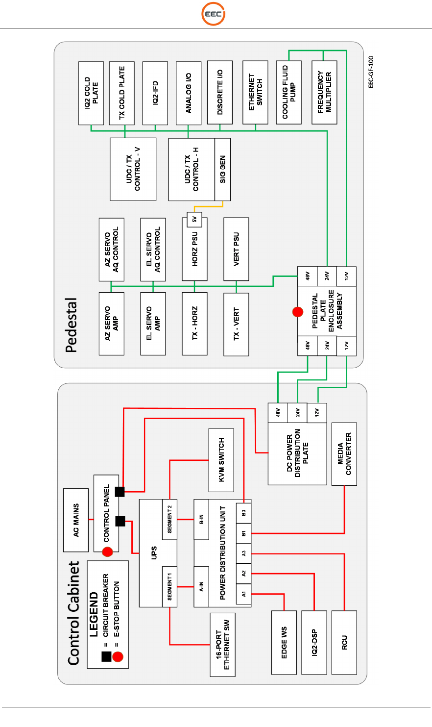
See Figure 66 for a block diagram showing the Primary Power Distribution through the Radar
System. For a more detailed drawing of the Power Control & Distribution Assembly, see the
Schematics and Circuit Diagrams.
Site power wires directly into the Power Control & Distribution Assembly into the Control Cabinet.
Power and ground cables connect to Field Terminals. Input power routes to the MAINS Circuit
Breaker on the E-Stop Panel Assembly (see Figure 16). DC Power controls through the Pedestal
Power circuit breaker (CB2) on the E-Stop Panel Assembly.
AC power is removed from the Ranger-X5 by use of any of the Emergency Stop switches (TX Indicator
Control Panel or Pedestal Enclosure). AC power is reset through the E-Stop Reset button located on the
E-Stop Panel Assembly.
A 2kVA UPS is an integral part of the system. The UPS power divides into two segments – 1
and 2. Segment 1 feeds the “A-Input” on the Power Distribution Unit. Segment 2 feeds the “B-
Input” on the PDU. The 16-Port Ethernet Switch and the KVM Switch are not controlled by the
PDU.
The Power Distribution Unit (PDU) provides the operator with remote command and control of
the power within the Ranger-X5. The PDU controls all of the operational aspects of the
machinery within Ranger-X5 – transmit, receive, antenna motion.
The Ranger-X5 is a DC powered radar system. The DC Power Plate feeds power to the Servo
System (AZ and EL), the Transceiver Units, the IQ2 Receiver system, and the cooling systems.
The DC Power Plate is controlled by a Circuit Breaker (CB2) on the output of the AC power of
port B2 on the Power Distribution Unit. CB2 can be interrupted by activating either of the two
E-Stop buttons.
T
ECHNICAL
D
OCUMENTATION
P
ROTECTING
P
EOPLE AND
A
SSETS
®
D
ATE
:
27
M
ARCH
2017
|
V
ERSION
:
1.8
77
R
ANGER
®
-
X5
R
ADAR
S
YSTEM
(M
OBILE
)
F
UNCTIONAL
O
VERVIEW AND
T
HEORY OF
O
PERATION
EEC
®
|
C
OMPANY
P
ROPRIETARY
Figure 66. Radar System Power Distribution

T
ECHNICAL
D
OCUMENTATION
P
ROTECTING
P
EOPLE AND
A
SSETS
®
D
ATE
:
27
M
ARCH
2017
|
V
ERSION
:
1.8
78
R
ANGER
®
-
X5
R
ADAR
S
YSTEM
(M
OBILE
)
F
UNCTIONAL
O
VERVIEW AND
T
HEORY OF
O
PERATION
EEC
®
|
C
OMPANY
P
ROPRIETARY
4.3. Interlock Circuitry
Use of Interlocks in the Ranger-X5 ensure safe operation of the radar. Should conditions
threatening the safety of personnel or equipment exist, they will inhibit some or all radar
operations. These interlocks are implemented using mechanical and electrical devices. The
interlocks fall into the following categories:
• Emergency Stop Circuitry - removes primary power from the system at the Power
Control & Distribution Assembly.
• Transmitter/Radiate inhibit - disables the ability of the Solid-State Power Amplifiers to
transmit by removing the radiate command line to the Transceiver Assembly.
• Antenna movement inhibit - disables movement of the Antenna in either or both axes by
removing power to the servo amplifiers and holding the controller in a reset condition.
• Antenna Power off - RCU commanded interlock to remove primary power to the
Pedestal using PED POWER RESET command.
4.3.1. Hardware Interlocks
Use of hardware interlocks in the Ranger-X5 electromechanically interrupt equipment operation
to protect personnel from exposed operating equipment, remove unsafe conditions, ensure safe
operations, or protect equipment from damage. These critical hardware interlocks place the radar
in a SAFE mode that could include disabling RF transmission, Antenna movement, or both RF
transmission and Antenna movement.
Any time the radar is put into operate mode when any axis was previously disabled and servo power is
commanded on, the Antenna homing sequence will be initiated.
The hardware interlocks that place the radar in SAFE mode include:
• Main Circuit Breaker (MAINS) - located on the TX Control and Indicator Panel - disables
the entire system by removing power.
• AZ Safe Switch - located on the Pedestal Enclosure Plate Assembly - disables azimuth
axis Antenna movement
• EL Safe Switch - located on the Pedestal Enclosure Plate Assembly - disables elevation
axis Antenna movement

T
ECHNICAL
D
OCUMENTATION
P
ROTECTING
P
EOPLE AND
A
SSETS
®
D
ATE
:
27
M
ARCH
2017
|
V
ERSION
:
1.8
79
R
ANGER
®
-
X5
R
ADAR
S
YSTEM
(M
OBILE
)
F
UNCTIONAL
O
VERVIEW AND
T
HEORY OF
O
PERATION
EEC
®
|
C
OMPANY
P
ROPRIETARY
4.3.2. Software Interlocks
Software interlocks are used to interrupt radar operations if certain conditions are present.
Configuration of the software interlocks is through the extensible markup language (XML) for the
I/O devices used by the BITE system. If a condition exists that is set to disable system operation,
the RCU will shut down the associated function and produce a BITE error message indicating the
fault that caused the error to occur.
All hardware interlocks are also software interlocked and produces a corresponding BITE
message. Software interlocks that disable the transmitter produce a tx_interlock fault BITE
message and the RCU will issue a “RADIATE OFF” command. Software interlocks that disable
both Azimuth and Elevation axes will generate a “SERVO OFF” indication from the RCU.
The following Software Interlocks are generated by the RCU:
• TX Interlock - opens the Radiate Command disabling the Transceivers.
• EL Interlock - disables elevation axis Antenna movement.
• AZ Interlock – disables azimuth axis Antenna movement.
• Mod Power Interlock – turns off the Transceivers.
• Antenna Power Interlock – removes primary power to the Pedestal using PED POWER
RESET command.
T
ECHNICAL
D
OCUMENTATION
P
ROTECTING
P
EOPLE AND
A
SSETS
®
D
ATE
:
27
M
ARCH
2017
|
V
ERSION
:
1.8
80
R
ANGER
®
-
X5
R
ADAR
S
YSTEM
(M
OBILE
)
F
UNCTIONAL
O
VERVIEW AND
T
HEORY OF
O
PERATION
EEC
®
|
C
OMPANY
P
ROPRIETARY
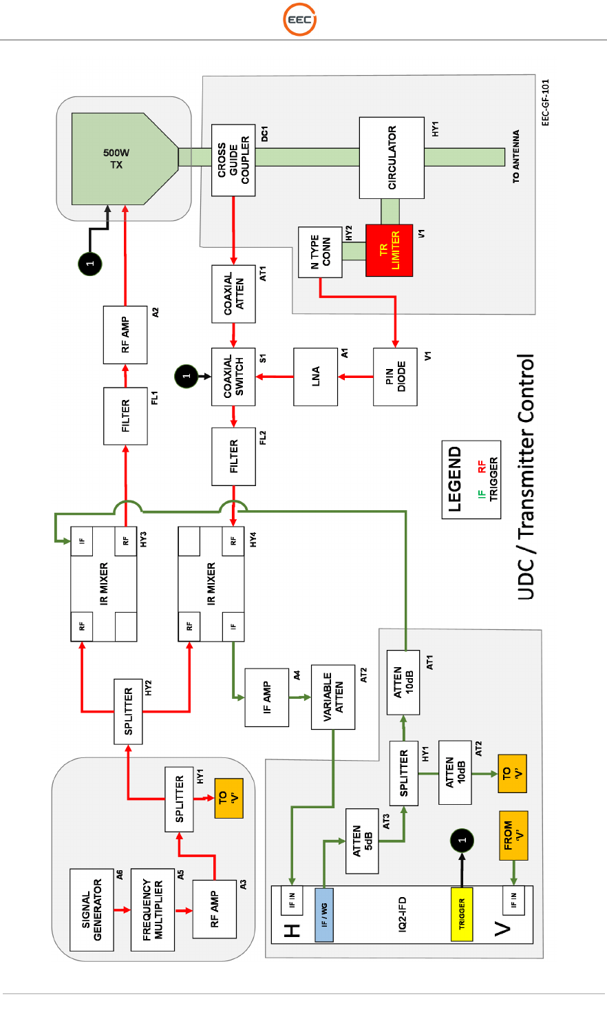
Figure 67.UDC / Transmitter Control

T
ECHNICAL
D
OCUMENTATION
P
ROTECTING
P
EOPLE AND
A
SSETS
®
D
ATE
:
27
M
ARCH
2017
|
V
ERSION
:
1.8
81
R
ANGER
®
-
X5
R
ADAR
S
YSTEM
(M
OBILE
)
F
UNCTIONAL
O
VERVIEW AND
T
HEORY OF
O
PERATION
EEC
®
|
C
OMPANY
P
ROPRIETARY
4.3.3. Radiate Command
Radiate is turned on automatically when EDGE is in the scheduler mode or by command from the
Surveillance screen “Radiate.” Radiate is also available in the LOCAL mode through the LCI screen
at the Control Cabinet console. Before the RCU will initiate a “radiate on” command, the system
must meet all software tx_interlock conditions, and the radar must be in a STANDBY status. The
RCU will initiate a “radiate on” command when commanded to radiate by the EDGE Software.
4.3.4. IF to RF Signal Up and Down Conversion
The Up-down converter (UDC) / Transmiter Control for the Ranger-X5 radar translates information
between the intermediate frequency (IF) and X-band operating frequencies. It is a high performance
unit which greatly reduces the size, weight and complexity of a microwave transceiver subsystem in
weather radar, while maintaining excellent performance characteristics. The UDC / Transmit Control
system provides the local oscillator signals to both the up-converter and down-converter and utilizes
other components, such as filters, low-noise amplifiers (LNA), and RF Amplifier all integrated in the
same RF assembly.
A pulsed waveform produced by the IQ2 at the IF frequency of 60MHz drives the up converter, which
translates the signal to the desired X-band frequency. A range of RF values are available to select
as the up converter output, ranging from 9.2 to 9.7GHz with 20MHz resolution and controlled through
a serial interface. An on-board PLL and frequency synthesizer utilizes the 100MHz reference
oscillator signal and provides the LO to the single stage mixing network. Similarly, the down
conversion block mixes the RF signal with the LO to produce the 60MHz IF signal, then is passed
to the IQ2 for base band digitization. Prior to the RF input on the down conversion stage, a pre-
amplifier network ensures that the dynamic range of the transmitter assembly block is matched to
the input of the digital receiver, maximizing the capabilities of the system.
The UDC is a breakthrough in achieving excellent performance of image rejection (without narrow
band filters in the module or multiple conversion states), TR isolation, and phase noise in an
integrated module. This UDC design combines a very simple single-stage conversion structure and
image-rejection mixer technology, which achieves strong image rejection performance without
onboard filters or multiple stages of conversion. This technology also helps reduce complexity and
minimize space requirements. The shielded RF enclosure helps to achieve the required level of TR
isolation. The PLL circuitry gives the phase noise performance and frequency agility, which are
normally available only in much more complex microwave signal sources. This also enhances the
radar system performance such as clutter visibility and Doppler accuracy.
4.3.5. Fiber-Optic Rotary Joint
The Fiber-Optic Rotary Joint provides the transition Fiber Optic cable transmission through the
azimuth axis.
4.4.
Receiver Signal Flow
The Ranger-X5 receiver (see Figure 67) is fully contained within the Payload Support Assembly on
the Pedestal. It is an integral part of the UDC and includes the UDC and IQ2-IFD.
4.4.1. IQ2-IFD
The IQ2-IFD receives the horizontal and vertical receive IF from the two UDCs. The IQ2-IFD digitizes

T
ECHNICAL
D
OCUMENTATION
P
ROTECTING
P
EOPLE AND
A
SSETS
®
D
ATE
:
27
M
ARCH
2017
|
V
ERSION
:
1.8
82
R
ANGER
®
-
X5
R
ADAR
S
YSTEM
(M
OBILE
)
F
UNCTIONAL
O
VERVIEW AND
T
HEORY OF
O
PERATION
EEC
®
|
C
OMPANY
P
ROPRIETARY
the received IF and outputs I and Q serial data through fiber-optic cable to the Fiber-Optic Rotary
Joint. The data is coupled through the Fiber-Optic Rotary Joint and sent to the IQ2-DSP in the
Control Cabinet.
4.4.2. IQ2-DSP
The IQ2-DSP digitally processes the “I and Q” data stream from the IQ2-IFD, already broken into
range-gate intervals, with floating-point algorithms to provide all required moments.
4.5.
Antenna Control
The user utilized the EDGE software or the LCI software on the RCU to send commands or EDGE
Software to provide Antenna control. The positioning commands are provided through an Ethernet
connection to each axis Aquarian Servo Controller Module, which develops the drive signal for the
Servo Amplifier and drive motors to move the Antenna.
The RCU breaks the high level command down into intermediate motion type, some are simple
(Point, PPI) some are more complex and require the RCU to execute a state machine to control the
desired motion (Sector, RHI). Once the RCU converts the high level command into a intermediate
level it is sent to the servo control for further processing.
The Aquarian takes an intermediate level command from the RCU to generate a motion profile in
real time. This process is known as trajectory generation. For the desired motions to be successful,
the trajectory generator outputs a command for each sample period telling the servo system the
position of the motor. The Aquarian samples the encoder for each position axis. The actual position
combined with the trajectory information creates a closed loop drive signal known as “error.” The
servo amplifier uses the “error” signal to actual the DC brushless motor.
The moving mass of the antenna system can be a hazard to personnel when performing maintenance on
the radar system. The Aquarian controller has a “safe input” that requires a ground signal to be applied in
order for the antenna to operate in a normal fashion.
4.5.1. Angle Acquisition
The Aquarian samples the incremental encoder via a dedicated high-speed quadrature Integrated
Circuit decoder. The sampled encoder positions are converted to angular data in degrees. This
resolved position uses a feedback in the closed loop control and is sent to the RCU. The RCU
receives angle data via Ethernet from the Aquarian. This data is corrected for true north by an offset
stored in the RCU. The data is transferred to the signal processor via high-speed RS422 serial link.
4.5.2. Homing Sequence
A homing sequence is required for each axis in order to resolve the incremental units of the axis

T
ECHNICAL
D
OCUMENTATION
P
ROTECTING
P
EOPLE AND
A
SSETS
®
D
ATE
:
27
M
ARCH
2017
|
V
ERSION
:
1.8
83
R
ANGER
®
-
X5
R
ADAR
S
YSTEM
(M
OBILE
)
F
UNCTIONAL
O
VERVIEW AND
T
HEORY OF
O
PERATION
EEC
®
|
C
OMPANY
P
ROPRIETARY
encoders and convert them to an absolute angle. The Aquarian performs this when a restart of the
controller causes the loss of the zero set point on an axis and there is a request for servo power. In
azimuth, the motor is driven clockwise until the homing sensor is detected and the quadrature
decoder hardware is reset to zero. In elevation, the motor is driven until it reaches the lower electrical
limit. Once the lower electrical limit is detected, the motor will drive in the opposite direction until it
detects the homing sensor. At that point, the quadrature encoder hardware is reset to zero.
4.6.
Communication Interface
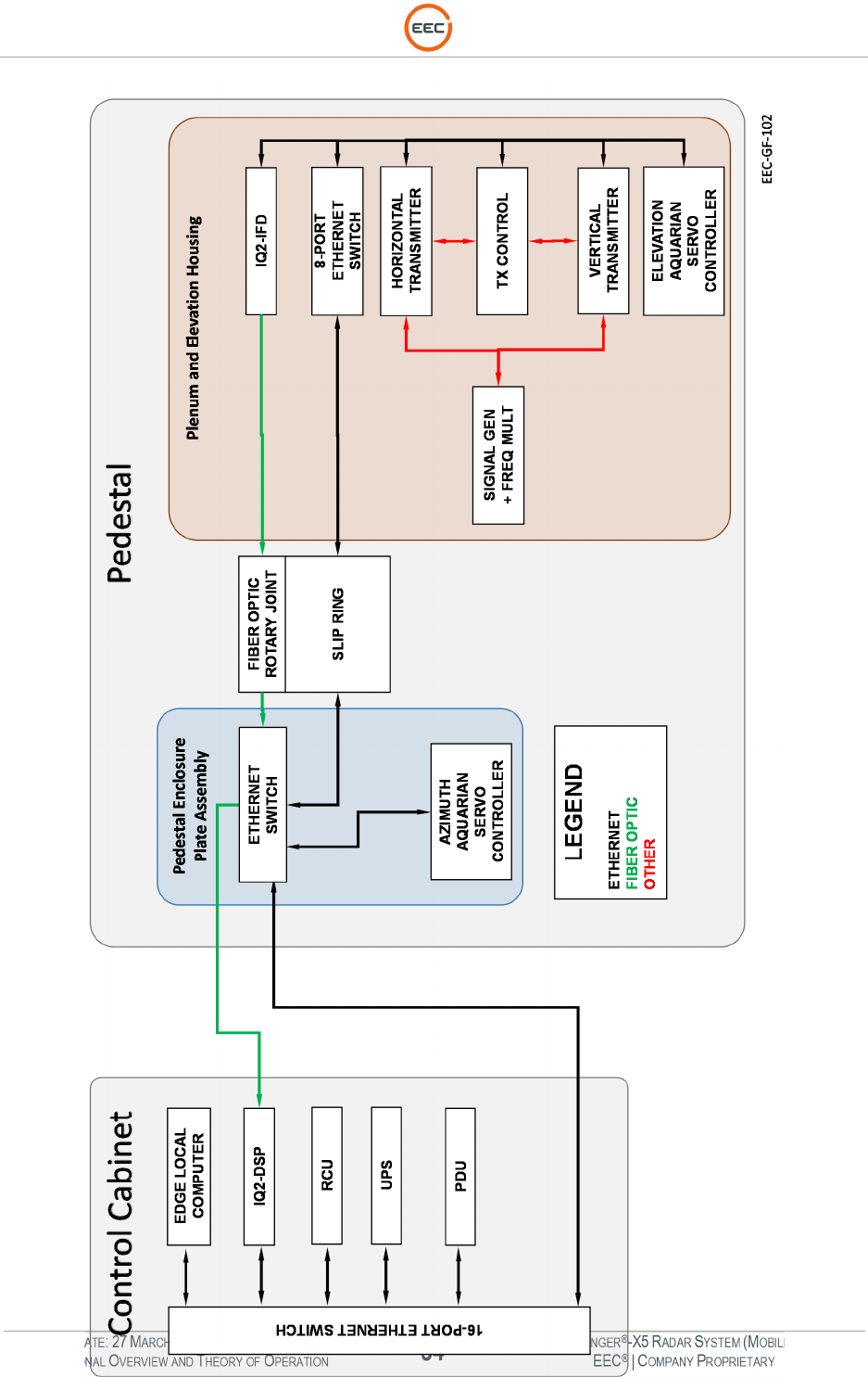
The radar uses an Ethernet network (see Figure 68) to provide command and control of the radar
set and to receive status flags and BITE information. Three Ethernet switches provide connection
points for all the I/O and controlled devices in the Control Cabinet, the Pedestal Enclosure, and RF
Enclosure.
Ethernet communications between the Pedestal and the Control Cabinet are provided over a fiber-
optic connection by the use of Ethernet Switches with Fiber-Optic Media Converters in the Control
Cabinet and Pedestal Enclosure. Communications within the Pedestal is possible by the use of the
Ethernet connection through the Slip-ring Module. Communications between the Radar and the
local host computer are provided through the rear panel of the Control Cabinet. Additional ports on
the front and rear of the Control Cabinet provide access to the radar network for expandability and
testing.
Received data from the IQ2-IFD, on the Pedestal, is transmitted via a fiber-optic cable through the
Fiber-Optic Rotary Joint to the downlink input and the IQ2-DSP. Uplink information is transmitted
from the IQ2-DSP over the Ethernet network to the IQ2-IFD.
T
ECHNICAL
D
OCUMENTATION
P
ROTECTING
P
EOPLE AND
A
SSETS
®
D
ATE
:
27
M
ARCH
2017
|
V
ERSION
:
1.8
84
R
ANGER
®
-
X5
R
ADAR
S
YSTEM
(M
OBILE
)
F
UNCTIONAL
O
VERVIEW AND
T
HEORY OF
O
PERATION
EEC
®
|
C
OMPANY
P
ROPRIETARY

T
ECHNICAL
D
OCUMENTATION
P
ROTECTING
P
EOPLE AND
A
SSETS
®
D
ATE
:
27
M
ARCH
2017
|
V
ERSION
:
1.8
85
R
ANGER
®
-
X5
R
ADAR
S
YSTEM
(M
OBILE
)
F
UNCTIONAL
O
VERVIEW AND
T
HEORY OF
O
PERATION
EEC
®
|
C
OMPANY
P
ROPRIETARY
Figure 68.Ranger-X5 Communication
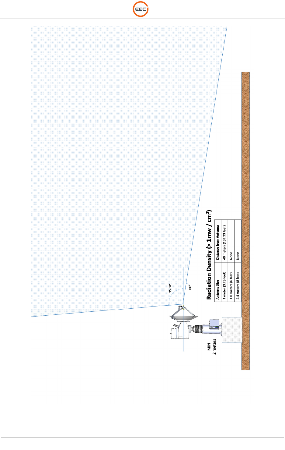
4.6.1. Radiation Safety
RF Hazard regulations are in place to protect personnel from harmful RF exposure. The primary
effect of RF exposure is thermal. Exposure to RF energy will cause an increase in the thermal
energy of the body’s molecules. The heating effect is very similar to how our microwave ovens cook
our food. Because of this, Enterprise Electronics Corporation (EEC) weather radar systems are
designed with safety at the top of the list.
The Ranger-X5 is a low powered radar system with only 500 watts of power per channel (horizontal
and vertical). Even with the longer pulse widths (100 microseconds) the power density is relatively
small.
The United States Federal Communications Commission (FCC) and International Commission on
Non-Ionizing Radiation Protection (ICNIRP) have established the same MPE limits based on
person’s awareness of the RF hazard. Two exposure limits exist, Occupational/Controlled and
General Population/Uncontrolled. Below is an excerpt from FCC OET 65 explaining the differences1.
“Occupational/Controlled exposure limits apply to situations in which persons are exposed as a
consequence of their employment and in which those persons who are exposed have been made
fully aware of the potential for exposure and can exercise control over their exposure.”
“General Population/Uncontrolled exposure limits apply to situations in which the general public may
be exposed or in which persons who are exposed as a consequence of their employment may not
be made fully aware of the potential for exposure or cannot exercise control over their exposure.
Therefore, members of the general public would always be considered under this category when
exposure is not employment-related.”
In order to protect personnel, the minimum safety distances for the General Population has been
computed and is diagrammed in Figure 69.
T
ECHNICAL
D
OCUMENTATION
P
ROTECTING
P
EOPLE AND
A
SSETS
®
D
ATE
:
27
M
ARCH
2017
|
V
ERSION
:
1.8
86
R
ANGER
®
-
X5
R
ADAR
S
YSTEM
(M
OBILE
)
F
UNCTIONAL
O
VERVIEW AND
T
HEORY OF
O
PERATION
EEC
®
|
C
OMPANY
P
ROPRIETARY
Figure 69. Radiation Hazard Zone – General Population

T
ECHNICAL
D
OCUMENTATION
P
ROTECTING
P
EOPLE AND
A
SSETS
®
D
ATE
:
27
M
ARCH
2017
|
V
ERSION
:
1.8
87
R
ANGER
®
-
X5
R
ADAR
S
YSTEM
(M
OBILE
)
F
UNCTIONAL
O
VERVIEW AND
T
HEORY OF
O
PERATION
EEC
®
|
C
OMPANY
P
ROPRIETARY
CHAPTER 5
S
YSTEM
S
TARTUP
/
S
HUTDOWN

T
ECHNICAL
D
OCUMENTATION
P
ROTECTING
P
EOPLE AND
A
SSETS
®
D
ATE
:
27
M
ARCH
2017
|
V
ERSION
:
1.8
88
R
ANGER
®
-
X5
R
ADAR
S
YSTEM
(M
OBILE
)
F
UNCTIONAL
O
VERVIEW AND
T
HEORY OF
O
PERATION
EEC
®
|
C
OMPANY
P
ROPRIETARY
This page intentionally blank.
T
ECHNICAL
D
OCUMENTATION
P
ROTECTING
P
EOPLE AND
A
SSETS
®
D
ATE
:
27
M
ARCH
2017
|
V
ERSION
:
1.8
89
R
ANGER
®
-
X5
R
ADAR
S
YSTEM
(M
OBILE
)
F
UNCTIONAL
O
VERVIEW AND
T
HEORY OF
O
PERATION
EEC
®
|
C
OMPANY
P
ROPRIETARY
5.
System Startup / Shutdown
The Startup and Shutdown Procedures include:
• OPTION: Powering on the Generator, UPS, and other components (see Appropriate
Vendor Instructions)
• OPTION: Connecting the Communication System (See Appropriate Vendor Instructions)
• Starting the Radar System (see Paragraph 5.1)
5.1.
Ranger-X5 Power Procedures
5.1.1. Radar Power-On Procedure
For the safety of the maintenance personnel, DO NOT power-on the Ranger-X5 Radar System until
a safety inspection of the equipment is complete to ensure personnel are clear from high-voltage
components and the moving parts of the antenna/pedestal.
The complexities and design of the Ranger-X5 radar system requires training for personnel that will
operate and maintain the radar system.
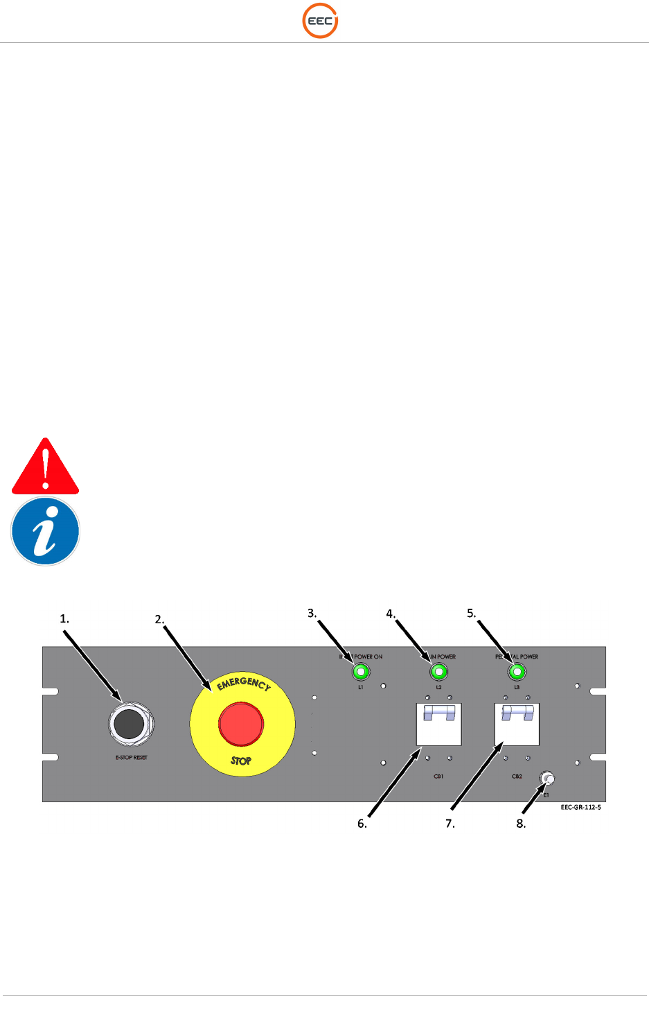
The various components in the radar system will require the power switches and circuit breakers to be in
the [ON] position before starting the radar system with the reset button.
Figure 70. Emergency Stop Panel
T
ECHNICAL
D
OCUMENTATION
P
ROTECTING
P
EOPLE AND
A
SSETS
®
D
ATE
:
27
M
ARCH
2017
|
V
ERSION
:
1.8
90
R
ANGER
®
-
X5
R
ADAR
S
YSTEM
(M
OBILE
)
F
UNCTIONAL
O
VERVIEW AND
T
HEORY OF
O
PERATION
EEC
®
|
C
OMPANY
P
ROPRIETARY
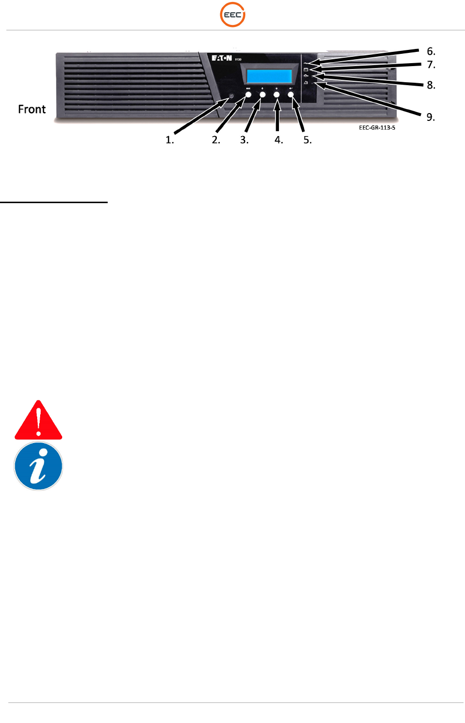
Figure 71. UPS
Power On Sequence:
1. On the Emergency Stop Panel (see Figure 70, Point 6), ensure the Main Breaker
(CB1) is in the [ON] position.
2. On the Emergency Stop Panel (see Figure 70, Point 7), ensure the Pedestal Breaker
(CB2) is in the [ON] position.
3. On the Radar System UPS (see Figure 71, Point 1), press and hold the power button
until the UPS power on.
4. Wait for the Power Distribution and Control Unit (see paragraph 1.1.6) to power on
(approximately 2 minutes).
5. Press and hold the E-Stop Reset Button (see Figure 70, Point 1) for 2-3 seconds, then
release.
When the pedestal is initially powered on it will begin a warm-up and alignment process. The pedestal
will rotate in azimuth as well as move up and down in elevation following a pre-programmed homing
sequence. At the end of the homing process, the pedestal will rotate in azimuth until it reaches its home
position, which is a variable position. The pedestal may pause at this position for a brief moment.
6. Ensure the power to the system is active by checking the various components in the
Control Cabinet and verifying the lights (see Figure 70, Point 3, 4, and 5) are
illuminated.
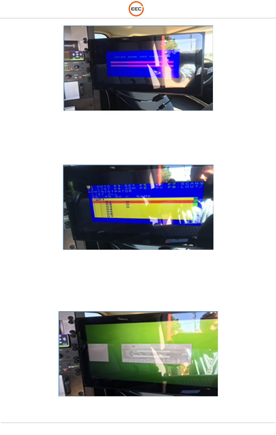
a. Ensure the KVM monitor displays the blue and magenta login screen (see Figure
72, below.)
T
ECHNICAL
D
OCUMENTATION
P
ROTECTING
P
EOPLE AND
A
SSETS
®
D
ATE
:
27
M
ARCH
2017
|
V
ERSION
:
1.8
91
R
ANGER
®
-
X5
R
ADAR
S
YSTEM
(M
OBILE
)
F
UNCTIONAL
O
VERVIEW AND
T
HEORY OF
O
PERATION
EEC
®
|
C
OMPANY
P
ROPRIETARY
Figure 72. KVM Login Screen
b. Press “enter” twice to skip past the login prompt in Figure 72. You will reach a blue
and yellow Selection screen (see Figure 73.)
Figure 73. KVM Selection Screen
c. Use the down arrow to highlight the option (01) and then press the “enter” key to
selection option (01). This will open the EDGE (OpenSuSE) login screen (green
background), as shown in Figure 74.
Figure 74. OpenSuSE (EDGE) Login Screen
d. Login to the EDGE computer using the credentials supplied with the radar system.
T
ECHNICAL
D
OCUMENTATION
P
ROTECTING
P
EOPLE AND
A
SSETS
®
D
ATE
:
27
M
ARCH
2017
|
V
ERSION
:
1.8
92
R
ANGER
®
-
X5
R
ADAR
S
YSTEM
(M
OBILE
)
F
UNCTIONAL
O
VERVIEW AND
T
HEORY OF
O
PERATION
EEC
®
|
C
OMPANY
P
ROPRIETARY
Normally, it is:
i. User ID: root
ii. Password: eecj#### (where #### us the job number for the production unit –
ex. eecj9818 or eecj9821
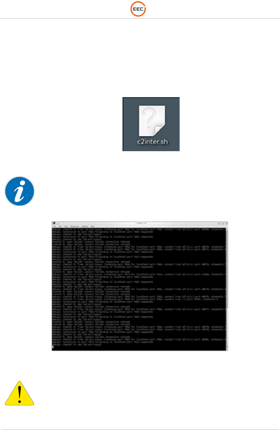
e. After completing the EDGE login, the OpenSuSE desktop will display. From the
selection of desktop icons, run the “c2inter.sh” icon as shown in Figure 75.
Figure 75. EDGE A to EDGE B Script ICON
This icon runs a script that establishes communication between the radar’s EDGE “A” computer and an
online VPS server used to communicate with the EDGE “B” remote computer located at the TV studio.
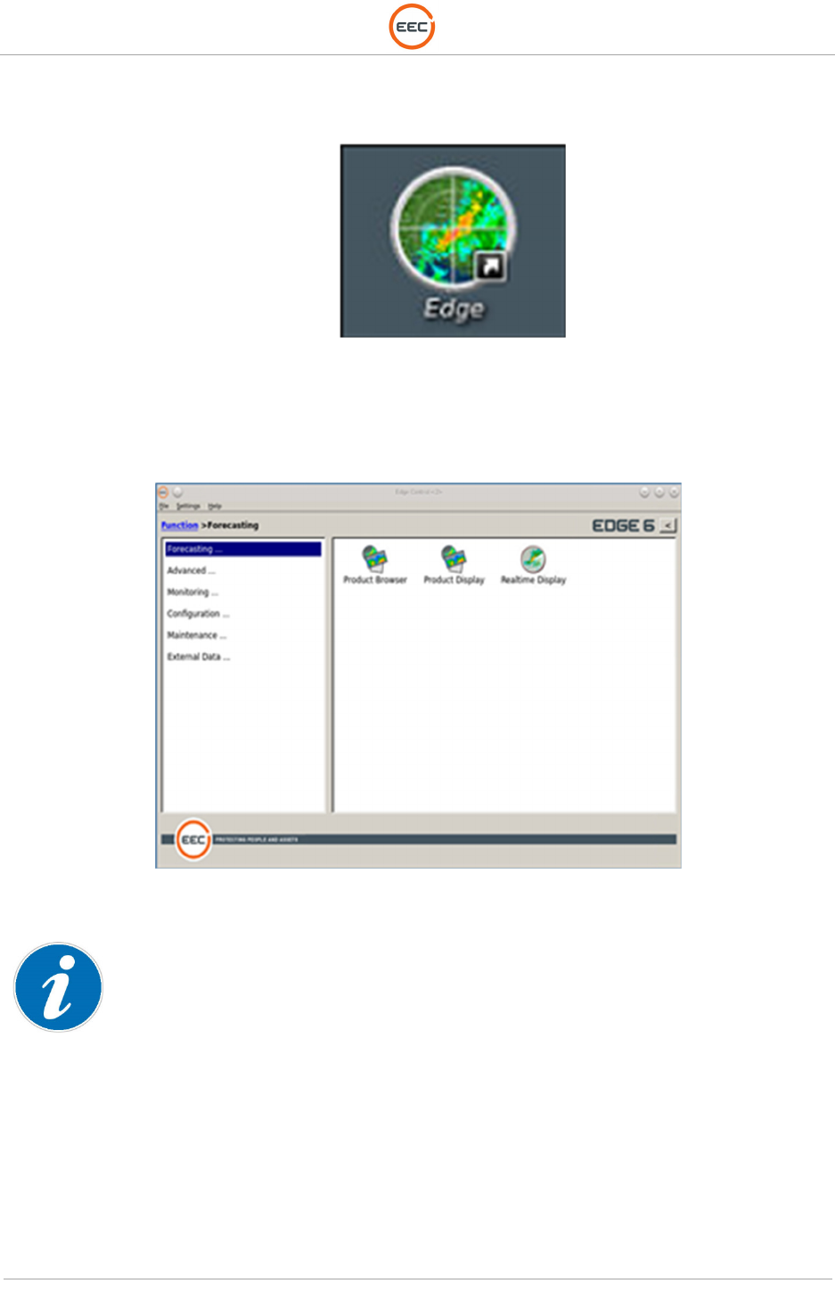
After selecting the icon the script will begin to run and appear similar to Figure 76.
Figure 76. EDGE Communications Window
The EDGE Communications Window may be minimized but it MUST remain running in the background to
maintain communication between the Local Radar System workstation and the REMOTE EDGE
workstation (normally studio or weather station). Use the down arrow at the upper right-hand corner of the
display to minimize, but not close this window.
f. After minimizing the window in Step e., select the EDGE icon located on the
T
ECHNICAL
D
OCUMENTATION
P
ROTECTING
P
EOPLE AND
A
SSETS
®
D
ATE
:
27
M
ARCH
2017
|
V
ERSION
:
1.8
93
R
ANGER
®
-
X5
R
ADAR
S
YSTEM
(M
OBILE
)
F
UNCTIONAL
O
VERVIEW AND
T
HEORY OF
O
PERATION
EEC
®
|
C
OMPANY
P
ROPRIETARY
OpenSuSE desktop (see Figure 77). Click the icon to open the EDGE program.
.
Figure 77. EDGE Application Icon
g. The EDGE “Control Menu” will display once the program starts.
Figure 78. EDGE Control Menu
Refer to the EDGE Operations Manual for Operational Instructions using the EDGE software.
5.1.1.1. Verification of Alignment to True North
1. After all components are powered “ON,” the pedestal should have successfully “homed”
and “aligned” facing the forward position (based on Paragraph 5.1.1, Step 5.) It will
continue, automatically, to adjust itself to “True North” as described in this Verification.
2. After aligning with the front of the unit, the antenna will remain in that position until the
EDGE software receives the GPS / Compass information from the GPS / Compass
T
ECHNICAL
D
OCUMENTATION
P
ROTECTING
P
EOPLE AND
A
SSETS
®
D
ATE
:
27
M
ARCH
2017
|
V
ERSION
:
1.8
94
R
ANGER
®
-
X5
R
ADAR
S
YSTEM
(M
OBILE
)
F
UNCTIONAL
O
VERVIEW AND
T
HEORY OF
O
PERATION
EEC
®
|
C
OMPANY
P
ROPRIETARY
system. EDGE will update the latitude and longitude of the radar system based on
input from the GPS / Compass unit. Please allow five to ten minutes for this process to
complete.
3. After the latitude and longitude are updated and when the EDGE system has received
enough information to determine “True North,” the antenna will automatically realign
itself to “True North” and it will be ready for operational use.
Please note, the radar can be operated after initial HOMING of the antenna is complete. However, the
EDGE display for weather and other data will not be aligned with “True North” and therefore, their
positions on the map will not be in the proper location relative to North.
5.1.2. Power-Off Procedure / System Shutdown
For the safety of the maintenance personnel, they MUST complete the following system power off
sequence before attempting any maintenance procedures.
The complexities and design of the Ranger-X5 radar system requires training for personnel that will
operate and maintain the radar system.
The various components in the radar system will require the power switches and circuit breakers to be in
the [OFF] position before performing maintenance.
5.1.2.1. Normal Power-Off Procedure
1. Power Down (in sequence) the following items.
a. EDGE Local Host Computer (see Figure 8, Point 5 for switch location)
b. IQ2-Digital Signal Processor (see Figure 6, Point 1 for switch location)
c. RCU Computer (see Figure 5, Point 1 for switch location)
d. UPS System (Figure 71, Point 1), press and hold the power button until the
UPS powers off.
2. On the Emergency Stop Panel (see Figure 70, Point 7), switch the Pedestal Breaker
(CB2) to the [OFF] position.
3. On the Emergency Stop Panel (see Figure 70, Point 6), switch the Main Breaker (CB1)
to the [OFF] position.
4. Refer to Appropriate Vendor Documentation for shutdown and tear down procedures

T
ECHNICAL
D
OCUMENTATION
P
ROTECTING
P
EOPLE AND
A
SSETS
®
D
ATE
:
27
M
ARCH
2017
|
V
ERSION
:
1.8
95
R
ANGER
®
-
X5
R
ADAR
S
YSTEM
(M
OBILE
)
F
UNCTIONAL
O
VERVIEW AND
T
HEORY OF
O
PERATION
EEC
®
|
C
OMPANY
P
ROPRIETARY
for all other equipment (i.e. UPS, Generator, Scissor Lift, Outriggers,
Communications Systems, GPS, etc).
5.1.2.2. Emergency Power-Off Procedure
The E-STOP Button removes power from the pedestal. It DOES NOT remove power from the Control
Cabinet.
1. Press the Pedestal Emergency Stop Button (see Figure 56, Point 2) or the Main
System Emergency Stop Button (see Figure 70, Point 2).
2. On the Emergency Stop Panel (see Figure 70, Point 6), switch the Main Breaker (CB1)
to the OFF Position.

T
ECHNICAL
D
OCUMENTATION
P
ROTECTING
P
EOPLE AND
A
SSETS
®
D
ATE
:
27
M
ARCH
2017
|
V
ERSION
:
1.8
96
R
ANGER
®
-
X5
R
ADAR
S
YSTEM
(M
OBILE
)
F
UNCTIONAL
O
VERVIEW AND
T
HEORY OF
O
PERATION
EEC
®
|
C
OMPANY
P
ROPRIETARY
This page intentionally blank