Exalt Wireless 105P25M 5 GHz Point to Point Fixed Link Radio Module User Manual
Exalt Wireless, Inc. 5 GHz Point to Point Fixed Link Radio Module
Contents
User Manual 1
Exalt Installation and Management Guide
EX-i Series (TDD)
206501-019 i
2016-05-24
EX-i Series (TDD)
Digital Microwave Radios
Installation and Management Guide
Models:
EX-2.4i/EX-2.4i Lite
EX-2.4i-16/EX-2.4i-16 K
EX-4.9i
EX-5i/EX-5i Lite
EX-5i-16/EX-5i-16 K
EX-5i-DS3

Exalt Installation and Management Guide
EX-i Series (TDD) Digital Microwave Radios
ii 206501-019
2016-05-24
Legal Notice
The information contained herein is the property of Exalt Wireless, Inc. (“Exalt”) and is supplied
without liability for errors or omissions. No part of this document may be reproduced, in any form,
except as authorized by contract or other written permission from the owner.
Any brand names and product names included in this manual are trademarks, registered trademarks, or
trade names of their respective holders.
The contents of this document are current as of the date of publication. Exalt reserves the right to
change the contents without prior notice.
The publication of information in this document does not imply freedom from patent or other rights of
Exalt or others.
© 2011 Exalt Wireless Inc. All rights reserved. The Exalt logo is a trademark of Exalt Wireless, Inc.
ExtendAir is a registered trademark of Exalt Wireless Inc.
Open-Source License Information
Per the terms of your Exalt Limited Hardware Warranty, Software License, and RMA Procedures
Agreement with Exalt Wireless, Inc. and/or its subsidiaries, certain Third Party Software may be
provided with and as part of the Exalt products provided to you, and any such Third Party Software
files provided are governed by the terms of their separate Third Party Licenses, which licenses give
you at least the license rights licensed to you in the Exalt End User Agreement and may give you
additional license rights as to the Third Party Software, but only with respect to the particular Third
Party Software to which the Third Party License applies.
The Exalt Products may include or be bundled with some or all of the following third party software.
Copies of the copyright notices and license agreements for any or all of these may be requested by
contacting Exalt support at email: support@exaltcom.com.
Open Source Code License Agreement Website
Embedded Linux - OS
U-Boot Boot Code. Both licensed under GPL Version 3 www.gnu.org
www.sourceforge.net
Busy Box Linux Commands. Licensed under GPL Version 2 www.gnu.org and
www.busybox.net
Scew Expat Wrapper. Licensed under LGPL Version 3 www.gnu.org
OpenSSL SSL Web Access. Licensed under dual license www.openssl.org
Net-SNMP SNMP Agent. Licensed under NetSNMP (see
Copyright Notices)
Dropbear SSH 2 Server; Expat - XML Parser; BarelyFitz –
Java Script Tabifier; jQuery; and Flotr – Java Script
Plotting Library. All of which are licensed under
MIT License
www.opensource.org/
licenses/mit-license.php
GoAhead Webserver Licensed under GoAhead License Agreement www.goahead.com

Exalt Installation and Management Guide
EX-i Series (TDD) Digital Microwave Radios
206501-019 iii
2016-05-24
Table of Contents
Legal Notice . . . . . . . . . . . . . . . . . . . . . . . . . . . . . . . . . . . . . . . . . . . . . . . . . . . . . . . . . . . . . . . ii
Open-Source License Information . . . . . . . . . . . . . . . . . . . . . . . . . . . . . . . . . . . . . . . . . . . . . . ii
List of Figures . . . . . . . . . . . . . . . . . . . . . . . . . . . . . . . . . . . . . . . . . . . . . . . . . . . . . . . . . . . . vii
List of Tables . . . . . . . . . . . . . . . . . . . . . . . . . . . . . . . . . . . . . . . . . . . . . . . . . . . . . . . . . . . . viii
About this Document . . . . . . . . . . . . . . . . . . . . . . . . . . . . . . . . . . . . . . . . . . . . . . . . . . . . . . . ix
Revision History . . . . . . . . . . . . . . . . . . . . . . . . . . . . . . . . . . . . . . . . . . . . . . . . . . . . . . . ix
Icons . . . . . . . . . . . . . . . . . . . . . . . . . . . . . . . . . . . . . . . . . . . . . . . . . . . . . . . . . . . . . . . . . . x
Introduction . . . . . . . . . . . . . . . . . . . . . . . . . . . . . . . . . . . . . . . . . . . . . . . . . . . . . . . . . . . . . . . 1
Related Documentation and Software . . . . . . . . . . . . . . . . . . . . . . . . . . . . . . . . . . . . . . . . 1
The Exalt i-Series Digital Microwave Radios . . . . . . . . . . . . . . . . . . . . . . . . . . . . . . . . . . 1
Pre-installation Tasks . . . . . . . . . . . . . . . . . . . . . . . . . . . . . . . . . . . . . . . . . . . . . . . . . . . . . . . . 6
Link Engineering and Site Planning . . . . . . . . . . . . . . . . . . . . . . . . . . . . . . . . . . . . . . . . . 6
Familiarization with the i-Series Radios . . . . . . . . . . . . . . . . . . . . . . . . . . . . . . . . . . . . . . 6
Shipping Box Contents . . . . . . . . . . . . . . . . . . . . . . . . . . . . . . . . . . . . . . . . . . . . . . . . . 7
Initial Configuration and Back-to-Back Bench Test . . . . . . . . . . . . . . . . . . . . . . . . . . . . . 8
RF Output Power Setting . . . . . . . . . . . . . . . . . . . . . . . . . . . . . . . . . . . . . . . . . . . . . . . . . . 9
Time Division Duplex (TDD) Factors . . . . . . . . . . . . . . . . . . . . . . . . . . . . . . . . . . . . . . . . 9
Link Orientation and Synchronization . . . . . . . . . . . . . . . . . . . . . . . . . . . . . . . . . . . . . . . 10
Radio A/B Configuration . . . . . . . . . . . . . . . . . . . . . . . . . . . . . . . . . . . . . . . . . . . . . . 11
Radio Synchronization . . . . . . . . . . . . . . . . . . . . . . . . . . . . . . . . . . . . . . . . . . . . . . . . . . . 12
Synchronization Modes . . . . . . . . . . . . . . . . . . . . . . . . . . . . . . . . . . . . . . . . . . . . . . . 12
Internal Synchronization. . . . . . . . . . . . . . . . . . . . . . . . . . . . . . . . . . . . . . . . . . . . . . . 12
External Synchronization . . . . . . . . . . . . . . . . . . . . . . . . . . . . . . . . . . . . . . . . . . . . . . 13
Offset Timing . . . . . . . . . . . . . . . . . . . . . . . . . . . . . . . . . . . . . . . . . . . . . . . . . . . . . . . . . . 14
When Sync is Lost . . . . . . . . . . . . . . . . . . . . . . . . . . . . . . . . . . . . . . . . . . . . . . . . . . . 15
LEDs . . . . . . . . . . . . . . . . . . . . . . . . . . . . . . . . . . . . . . . . . . . . . . . . . . . . . . . . . . . . . . 15
Virtual Local Area Network (VLAN) . . . . . . . . . . . . . . . . . . . . . . . . . . . . . . . . . . . . . . . 15
Link Symmetry . . . . . . . . . . . . . . . . . . . . . . . . . . . . . . . . . . . . . . . . . . . . . . . . . . . . . . . . 16
Simple Network Management Protocol (SNMP) . . . . . . . . . . . . . . . . . . . . . . . . . . . . . . 17
System Installation and Initiation Process . . . . . . . . . . . . . . . . . . . . . . . . . . . . . . . . . . . . . . . 18
Record Keeping . . . . . . . . . . . . . . . . . . . . . . . . . . . . . . . . . . . . . . . . . . . . . . . . . . . . . . . . 19
Installation . . . . . . . . . . . . . . . . . . . . . . . . . . . . . . . . . . . . . . . . . . . . . . . . . . . . . . . . . . . . . . . 20
Mechanical Configuration and Mounting . . . . . . . . . . . . . . . . . . . . . . . . . . . . . . . . . . . . 20
Rack Mounting . . . . . . . . . . . . . . . . . . . . . . . . . . . . . . . . . . . . . . . . . . . . . . . . . . . . . . 20
Table or Rack Shelf Mounting the System. . . . . . . . . . . . . . . . . . . . . . . . . . . . . . . . . 21
Radio Ports and Indicators . . . . . . . . . . . . . . . . . . . . . . . . . . . . . . . . . . . . . . . . . . . . . . . . 21
Connector Overview. . . . . . . . . . . . . . . . . . . . . . . . . . . . . . . . . . . . . . . . . . . . . . . . . . 22
LED Indicators . . . . . . . . . . . . . . . . . . . . . . . . . . . . . . . . . . . . . . . . . . . . . . . . . . . . . . 23
RMT (Remote) Button . . . . . . . . . . . . . . . . . . . . . . . . . . . . . . . . . . . . . . . . . . . . . . . . 25
Power . . . . . . . . . . . . . . . . . . . . . . . . . . . . . . . . . . . . . . . . . . . . . . . . . . . . . . . . . . . . . . . . 25
Terminating the RF Connector . . . . . . . . . . . . . . . . . . . . . . . . . . . . . . . . . . . . . . . . . . 25
AC Power . . . . . . . . . . . . . . . . . . . . . . . . . . . . . . . . . . . . . . . . . . . . . . . . . . . . . . . . . . 26
DC Power . . . . . . . . . . . . . . . . . . . . . . . . . . . . . . . . . . . . . . . . . . . . . . . . . . . . . . . . . . 26
Reset to Critical Factory Settings . . . . . . . . . . . . . . . . . . . . . . . . . . . . . . . . . . . . . . . . 28
Antenna/Transmission System . . . . . . . . . . . . . . . . . . . . . . . . . . . . . . . . . . . . . . . . . . . . 28
Initial Antenna Mounting . . . . . . . . . . . . . . . . . . . . . . . . . . . . . . . . . . . . . . . . . . . . . . 29

Exalt Installation and Management Guide
EX-i Series (TDD) Digital Microwave Radios
iv 206501-019
2016-05-24
Transmission Line from Antenna to Egress . . . . . . . . . . . . . . . . . . . . . . . . . . . . . . . . 29
RF Lightning Arrestor . . . . . . . . . . . . . . . . . . . . . . . . . . . . . . . . . . . . . . . . . . . . . . . . 31
Transmission Line from Egress to Radio . . . . . . . . . . . . . . . . . . . . . . . . . . . . . . . . . . 32
Antenna Alignment . . . . . . . . . . . . . . . . . . . . . . . . . . . . . . . . . . . . . . . . . . . . . . . . . . . . . 32
Configuration and Management . . . . . . . . . . . . . . . . . . . . . . . . . . . . . . . . . . . . . . . . . . . . . . 34
Command Line Interface (CLI) . . . . . . . . . . . . . . . . . . . . . . . . . . . . . . . . . . . . . . . . . . . . 34
Connect to the Radio with a Serial Connection . . . . . . . . . . . . . . . . . . . . . . . . . . . . . 34
Telnet into the Command Line Interface (CLI) . . . . . . . . . . . . . . . . . . . . . . . . . . . . . . . . 34
Connect to the Radio in a Telnet Session . . . . . . . . . . . . . . . . . . . . . . . . . . . . . . . . . . 34
Exalt Graphical User Interface (GUI) . . . . . . . . . . . . . . . . . . . . . . . . . . . . . . . . . . . . . . . 35
Preparing to Connect . . . . . . . . . . . . . . . . . . . . . . . . . . . . . . . . . . . . . . . . . . . . . . . . . 35
Log In . . . . . . . . . . . . . . . . . . . . . . . . . . . . . . . . . . . . . . . . . . . . . . . . . . . . . . . . . . . . . 36
Login Privileges . . . . . . . . . . . . . . . . . . . . . . . . . . . . . . . . . . . . . . . . . . . . . . . . . . . . . 37
Quick Start . . . . . . . . . . . . . . . . . . . . . . . . . . . . . . . . . . . . . . . . . . . . . . . . . . . . . . . . . . . . 38
Navigating the GUI . . . . . . . . . . . . . . . . . . . . . . . . . . . . . . . . . . . . . . . . . . . . . . . . . . . . . 39
Summary Status Section . . . . . . . . . . . . . . . . . . . . . . . . . . . . . . . . . . . . . . . . . . . . . . . 39
Navigation Panel. . . . . . . . . . . . . . . . . . . . . . . . . . . . . . . . . . . . . . . . . . . . . . . . . . . . . 40
Radio Information Page . . . . . . . . . . . . . . . . . . . . . . . . . . . . . . . . . . . . . . . . . . . . . . . . . . 42
Administration Settings Page . . . . . . . . . . . . . . . . . . . . . . . . . . . . . . . . . . . . . . . . . . . . . . 43
Simple Network Management Protocol (SNMP) Configuration . . . . . . . . . . . . . . . . . . . 45
SNMP v1/v2c/v3 Support Options . . . . . . . . . . . . . . . . . . . . . . . . . . . . . . . . . . . . . . . 45
SNMP Traps . . . . . . . . . . . . . . . . . . . . . . . . . . . . . . . . . . . . . . . . . . . . . . . . . . . . . . . . 46
File Transfer Page . . . . . . . . . . . . . . . . . . . . . . . . . . . . . . . . . . . . . . . . . . . . . . . . . . . . . . 48
File Activation Page . . . . . . . . . . . . . . . . . . . . . . . . . . . . . . . . . . . . . . . . . . . . . . . . . . . . . 51
Access Security Page . . . . . . . . . . . . . . . . . . . . . . . . . . . . . . . . . . . . . . . . . . . . . . . . . . . . 52
System Configuration Page . . . . . . . . . . . . . . . . . . . . . . . . . . . . . . . . . . . . . . . . . . . . . . . 54
MHS Configuration Page . . . . . . . . . . . . . . . . . . . . . . . . . . . . . . . . . . . . . . . . . . . . . . . . . 58
Ethernet Interface Configuration Page . . . . . . . . . . . . . . . . . . . . . . . . . . . . . . . . . . . . . . 59
VLAN Configuration Page . . . . . . . . . . . . . . . . . . . . . . . . . . . . . . . . . . . . . . . . . . . . . . . 60
T1/E1 Configuration Pages . . . . . . . . . . . . . . . . . . . . . . . . . . . . . . . . . . . . . . . . . . . . . . . 62
T1 Interface Configuration Page. . . . . . . . . . . . . . . . . . . . . . . . . . . . . . . . . . . . . . . . . 62
E1 Interface Configuration Page. . . . . . . . . . . . . . . . . . . . . . . . . . . . . . . . . . . . . . . . . 63
T1/E1 Loopback . . . . . . . . . . . . . . . . . . . . . . . . . . . . . . . . . . . . . . . . . . . . . . . . . . . . . 64
DS3 Configuration Page . . . . . . . . . . . . . . . . . . . . . . . . . . . . . . . . . . . . . . . . . . . . . . . . . 65
GPS Information Page . . . . . . . . . . . . . . . . . . . . . . . . . . . . . . . . . . . . . . . . . . . . . . . . . . . 66
Alarms Page . . . . . . . . . . . . . . . . . . . . . . . . . . . . . . . . . . . . . . . . . . . . . . . . . . . . . . . . . . . 67
MHS Status Page . . . . . . . . . . . . . . . . . . . . . . . . . . . . . . . . . . . . . . . . . . . . . . . . . . . . . . . 69
Performance Page . . . . . . . . . . . . . . . . . . . . . . . . . . . . . . . . . . . . . . . . . . . . . . . . . . . . . . 70
Event Log Page . . . . . . . . . . . . . . . . . . . . . . . . . . . . . . . . . . . . . . . . . . . . . . . . . . . . . . . . 72
User Throughput Page . . . . . . . . . . . . . . . . . . . . . . . . . . . . . . . . . . . . . . . . . . . . . . . . . . . 73
Diagnostic Charts Page . . . . . . . . . . . . . . . . . . . . . . . . . . . . . . . . . . . . . . . . . . . . . . . . . . 75
Spectrum Analyzer Page . . . . . . . . . . . . . . . . . . . . . . . . . . . . . . . . . . . . . . . . . . . . . . . . . 77
Ethernet Utilization Page . . . . . . . . . . . . . . . . . . . . . . . . . . . . . . . . . . . . . . . . . . . . . . . . . 79
Reboot Page . . . . . . . . . . . . . . . . . . . . . . . . . . . . . . . . . . . . . . . . . . . . . . . . . . . . . . . . . . . 80
Manual Page . . . . . . . . . . . . . . . . . . . . . . . . . . . . . . . . . . . . . . . . . . . . . . . . . . . . . . . . . . 81
Specifications . . . . . . . . . . . . . . . . . . . . . . . . . . . . . . . . . . . . . . . . . . . . . . . . . . . . . . . . . . . . . 82
Physical Specifications . . . . . . . . . . . . . . . . . . . . . . . . . . . . . . . . . . . . . . . . . . . . . . . . . . 82

Exalt Installation and Management Guide
EX-i Series (TDD) Digital Microwave Radios
206501-019 v
2016-05-24
Common System Specifications . . . . . . . . . . . . . . . . . . . . . . . . . . . . . . . . . . . . . . . . . . . 82
EX-2.4i System Specifications . . . . . . . . . . . . . . . . . . . . . . . . . . . . . . . . . . . . . . . . . . . . 83
EX-4.9i System Specifications . . . . . . . . . . . . . . . . . . . . . . . . . . . . . . . . . . . . . . . . . . . . 84
EX-5i System Specifications, 5.3GHz Band . . . . . . . . . . . . . . . . . . . . . . . . . . . . . . . . . . 85
EX-5i System Specifications, 5.4GHz Band . . . . . . . . . . . . . . . . . . . . . . . . . . . . . . . . . . 86
EX-5i System Specifications, 5.8GHz Band . . . . . . . . . . . . . . . . . . . . . . . . . . . . . . . . . . 87
Interfaces . . . . . . . . . . . . . . . . . . . . . . . . . . . . . . . . . . . . . . . . . . . . . . . . . . . . . . . . . . . . . 88
Interface Connections . . . . . . . . . . . . . . . . . . . . . . . . . . . . . . . . . . . . . . . . . . . . . . . . . . . . . . 90
T1/E1 Connections . . . . . . . . . . . . . . . . . . . . . . . . . . . . . . . . . . . . . . . . . . . . . . . . . . . . . 90
Ethernet Connections . . . . . . . . . . . . . . . . . . . . . . . . . . . . . . . . . . . . . . . . . . . . . . . . . . . . 91
Sync Connections . . . . . . . . . . . . . . . . . . . . . . . . . . . . . . . . . . . . . . . . . . . . . . . . . . . . . . 92
Alarm Connector . . . . . . . . . . . . . . . . . . . . . . . . . . . . . . . . . . . . . . . . . . . . . . . . . . . . . . . 93
Console Connector . . . . . . . . . . . . . . . . . . . . . . . . . . . . . . . . . . . . . . . . . . . . . . . . . . . . . . 94
DC Power Connector . . . . . . . . . . . . . . . . . . . . . . . . . . . . . . . . . . . . . . . . . . . . . . . . . . . . 95
DIP Switch Settings (-16 Models Only) . . . . . . . . . . . . . . . . . . . . . . . . . . . . . . . . . . . . . . . . 96
Antennas . . . . . . . . . . . . . . . . . . . . . . . . . . . . . . . . . . . . . . . . . . . . . . . . . . . . . . . . . . . . . . . . 98
DC Coupler for Antenna Alignment . . . . . . . . . . . . . . . . . . . . . . . . . . . . . . . . . . . . . . . . . . 100
Required Items . . . . . . . . . . . . . . . . . . . . . . . . . . . . . . . . . . . . . . . . . . . . . . . . . . . . . . . . 100
Interconnections . . . . . . . . . . . . . . . . . . . . . . . . . . . . . . . . . . . . . . . . . . . . . . . . . . . . . . . 100
Troubleshooting . . . . . . . . . . . . . . . . . . . . . . . . . . . . . . . . . . . . . . . . . . . . . . . . . . . . . . . . . . 102
General Practices . . . . . . . . . . . . . . . . . . . . . . . . . . . . . . . . . . . . . . . . . . . . . . . . . . . . . . 102
Typical Indications of Issues . . . . . . . . . . . . . . . . . . . . . . . . . . . . . . . . . . . . . . . . . . . . . 103
Improper RF Cable Termination . . . . . . . . . . . . . . . . . . . . . . . . . . . . . . . . . . . . . . . . . . 104
Multipath Propagation . . . . . . . . . . . . . . . . . . . . . . . . . . . . . . . . . . . . . . . . . . . . . . . . . . 104
RF Interference . . . . . . . . . . . . . . . . . . . . . . . . . . . . . . . . . . . . . . . . . . . . . . . . . . . . . . . 104
Path Obstruction . . . . . . . . . . . . . . . . . . . . . . . . . . . . . . . . . . . . . . . . . . . . . . . . . . . . . . 105
Misaligned Antenna . . . . . . . . . . . . . . . . . . . . . . . . . . . . . . . . . . . . . . . . . . . . . . . . . . . . 105
Faulty Antenna . . . . . . . . . . . . . . . . . . . . . . . . . . . . . . . . . . . . . . . . . . . . . . . . . . . . . . . . 105
Improper Grounding . . . . . . . . . . . . . . . . . . . . . . . . . . . . . . . . . . . . . . . . . . . . . . . . . . . 106
Insufficient Link Margin . . . . . . . . . . . . . . . . . . . . . . . . . . . . . . . . . . . . . . . . . . . . . . . . 106
Moisture in the Transmission System . . . . . . . . . . . . . . . . . . . . . . . . . . . . . . . . . . . . . . 106
Back-to-back Bench Testing . . . . . . . . . . . . . . . . . . . . . . . . . . . . . . . . . . . . . . . . . . . . . . . . 107
Basic Test . . . . . . . . . . . . . . . . . . . . . . . . . . . . . . . . . . . . . . . . . . . . . . . . . . . . . . . . . . . . 107
Specification Performance Verification . . . . . . . . . . . . . . . . . . . . . . . . . . . . . . . . . . . . . 108
General Compliance and Safety . . . . . . . . . . . . . . . . . . . . . . . . . . . . . . . . . . . . . . . . . . . . . 110
Dynamic Frequency Selection . . . . . . . . . . . . . . . . . . . . . . . . . . . . . . . . . . . . . . . . . . . . . . . 111
Safety Notices . . . . . . . . . . . . . . . . . . . . . . . . . . . . . . . . . . . . . . . . . . . . . . . . . . . . . . . . . . . 112
Regulatory Notices . . . . . . . . . . . . . . . . . . . . . . . . . . . . . . . . . . . . . . . . . . . . . . . . . . . . . . . 113
4.9GHz Model . . . . . . . . . . . . . . . . . . . . . . . . . . . . . . . . . . . . . . . . . . . . . . . . . . . . . . . . 113
United States Compliance . . . . . . . . . . . . . . . . . . . . . . . . . . . . . . . . . . . . . . . . . . . . . . . 113
Federal Communications Commission (FCC), United States . . . . . . . . . . . . . . . . . 113
Canada Compliance . . . . . . . . . . . . . . . . . . . . . . . . . . . . . . . . . . . . . . . . . . . . . . . . . . . . 114
Industry Canada (IC), Canada . . . . . . . . . . . . . . . . . . . . . . . . . . . . . . . . . . . . . . . . . 115
Antennas Supported in Canada. . . . . . . . . . . . . . . . . . . . . . . . . . . . . . . . . . . . . . . . . 115
Europe and ITU Country Compliance . . . . . . . . . . . . . . . . . . . . . . . . . . . . . . . . . . . . . . 115
Regulatory Compliance . . . . . . . . . . . . . . . . . . . . . . . . . . . . . . . . . . . . . . . . . . . . . . . . . . . . 117
Regulatory Domain Keys . . . . . . . . . . . . . . . . . . . . . . . . . . . . . . . . . . . . . . . . . . . . . . . . . . . 119

Exalt Installation and Management Guide
EX-i Series (TDD) Digital Microwave Radios
vi 206501-019
2016-05-24
EIRP Limits for the United States and Canada . . . . . . . . . . . . . . . . . . . . . . . . . . . . . . . . . . 120
EX-2.4i EIRP for the USA and Canada . . . . . . . . . . . . . . . . . . . . . . . . . . . . . . . . . . . . . 120
EX-4.9i EIRP for the USA and Canada . . . . . . . . . . . . . . . . . . . . . . . . . . . . . . . . . . . . . 120
EX-5i Series EIRP for the US and Canada . . . . . . . . . . . . . . . . . . . . . . . . . . . . . . . . . . 120
5250–5350 MHz Band . . . . . . . . . . . . . . . . . . . . . . . . . . . . . . . . . . . . . . . . . . . . . . . 120
5470–5725 MHz Band . . . . . . . . . . . . . . . . . . . . . . . . . . . . . . . . . . . . . . . . . . . . . . . 121
5725–5850 MHz Band . . . . . . . . . . . . . . . . . . . . . . . . . . . . . . . . . . . . . . . . . . . . . . . 121
EIRP Limits for the European Union and ITU Countries . . . . . . . . . . . . . . . . . . . . . . . . . . 122
EX-2.4i-Series EIRP . . . . . . . . . . . . . . . . . . . . . . . . . . . . . . . . . . . . . . . . . . . . . . . . . . . 122
EX-5i Series EIRP . . . . . . . . . . . . . . . . . . . . . . . . . . . . . . . . . . . . . . . . . . . . . . . . . . . . . 123
5250–5350 MHz band . . . . . . . . . . . . . . . . . . . . . . . . . . . . . . . . . . . . . . . . . . . . . . . 123
5470–5725 MHz band . . . . . . . . . . . . . . . . . . . . . . . . . . . . . . . . . . . . . . . . . . . . . . . 124
5725–5850 MHz band . . . . . . . . . . . . . . . . . . . . . . . . . . . . . . . . . . . . . . . . . . . . . . . 124
EIRP Limits for Australia . . . . . . . . . . . . . . . . . . . . . . . . . . . . . . . . . . . . . . . . . . . . . . . . . . 126
EX-5i Series EIRP for Australia . . . . . . . . . . . . . . . . . . . . . . . . . . . . . . . . . . . . . . . . . . 126
5470–5725 MHz Band . . . . . . . . . . . . . . . . . . . . . . . . . . . . . . . . . . . . . . . . . . . . . . . 126
5725–5850 MHz Band . . . . . . . . . . . . . . . . . . . . . . . . . . . . . . . . . . . . . . . . . . . . . . . 126
Declaration of Conformity to the R&TTE Directive
1999/5/EC . . . . . . . . . . . . . . . . . . . . . . . . . . . . . . . . . . . . . . . . . . . . . . . . . . . . . . . . . . . . . . 127
EU WEEE . . . . . . . . . . . . . . . . . . . . . . . . . . . . . . . . . . . . . . . . . . . . . . . . . . . . . . . . . . . 128
EU RoHS . . . . . . . . . . . . . . . . . . . . . . . . . . . . . . . . . . . . . . . . . . . . . . . . . . . . . . . . . . . . 128
END USER AGREEMENT . . . . . . . . . . . . . . . . . . . . . . . . . . . . . . . . . . . . . . . . . . . . . . . . 130
Copyright Notices . . . . . . . . . . . . . . . . . . . . . . . . . . . . . . . . . . . . . . . . . . . . . . . . . . . . . . . . 135
Index . . . . . . . . . . . . . . . . . . . . . . . . . . . . . . . . . . . . . . . . . . . . . . . . . . . . . . . . . . . . . . . . . . 139

Exalt Installation and Management Guide
EX-i Series (TDD) Digital Microwave Radios
206501-019 vii
2016-05-24
List of Figures
Figure 1 EX-2.4i Digital Microwave Radio . . . . . . . . . . . . . . . . . . . . . . . . . . . . . . . . . . . . . . . . . . 1
Figure 2 Indoor mount interconnection . . . . . . . . . . . . . . . . . . . . . . . . . . . . . . . . . . . . . . . . . . . . . . 4
Figure 3 Enclosure mount interconnection . . . . . . . . . . . . . . . . . . . . . . . . . . . . . . . . . . . . . . . . . . . 4
Figure 4 Basic radio interconnectivity using internal synchronization . . . . . . . . . . . . . . . . . . . . . 12
Figure 5 Collocated radios, one in AUTO SYNC mode to provide redundancy . . . . . . . . . . . . . 13
Figure 6 Multiple-link site configuration, using AUTO SYNC for redundancy . . . . . . . . . . . . . . 13
Figure 7 GPS as primary sync source using AUTO SYNC . . . . . . . . . . . . . . . . . . . . . . . . . . . . . . 14
Figure 8 Synchronized GPS sources using AUTO SYNC . . . . . . . . . . . . . . . . . . . . . . . . . . . . . . 14
Figure 9 Radio installation tasks . . . . . . . . . . . . . . . . . . . . . . . . . . . . . . . . . . . . . . . . . . . . . . . . . . 18
Figure 10 Front flush mount configuration . . . . . . . . . . . . . . . . . . . . . . . . . . . . . . . . . . . . . . . . . . . 20
Figure 11 Front projection mount configuration . . . . . . . . . . . . . . . . . . . . . . . . . . . . . . . . . . . . . . . 20
Figure 12 Rear-mount locations . . . . . . . . . . . . . . . . . . . . . . . . . . . . . . . . . . . . . . . . . . . . . . . . . . . . 21
Figure 13 Front panel (EX-2.4i, EX-4.9i, or EX-5i) . . . . . . . . . . . . . . . . . . . . . . . . . . . . . . . . . . . . 21
Figure 14 Front panel (EX-2.4i-16 or EX-5i-16) . . . . . . . . . . . . . . . . . . . . . . . . . . . . . . . . . . . . . . . 22
Figure 15 Front panel (EX-5i-DS3) . . . . . . . . . . . . . . . . . . . . . . . . . . . . . . . . . . . . . . . . . . . . . . . . . 22
Figure 16 Primary front panel connectors (standard models) . . . . . . . . . . . . . . . . . . . . . . . . . . . . . 22
Figure 17 EX-5i-DS3 connectors and grounding switches . . . . . . . . . . . . . . . . . . . . . . . . . . . . . . . 23
Figure 18 DC connector . . . . . . . . . . . . . . . . . . . . . . . . . . . . . . . . . . . . . . . . . . . . . . . . . . . . . . . . . . 27
Figure 19 CLI root menu . . . . . . . . . . . . . . . . . . . . . . . . . . . . . . . . . . . . . . . . . . . . . . . . . . . . . . . . . 35
Figure 20 Initiating the browser connection . . . . . . . . . . . . . . . . . . . . . . . . . . . . . . . . . . . . . . . . . . 36
Figure 21 Browser Login screens–model dependent . . . . . . . . . . . . . . . . . . . . . . . . . . . . . . . . . . . . 37
Figure 22 Radio Information page . . . . . . . . . . . . . . . . . . . . . . . . . . . . . . . . . . . . . . . . . . . . . . . . . . 38
Figure 23 Exalt GUI window description . . . . . . . . . . . . . . . . . . . . . . . . . . . . . . . . . . . . . . . . . . . . 39
Figure 24 Summary status information . . . . . . . . . . . . . . . . . . . . . . . . . . . . . . . . . . . . . . . . . . . . . . 40
Figure 25 Radio Information page . . . . . . . . . . . . . . . . . . . . . . . . . . . . . . . . . . . . . . . . . . . . . . . . . . 42
Figure 26 Administration Settings page . . . . . . . . . . . . . . . . . . . . . . . . . . . . . . . . . . . . . . . . . . . . . 43
Figure 27 Changed fields and Update button . . . . . . . . . . . . . . . . . . . . . . . . . . . . . . . . . . . . . . . . . 43
Figure 28 SNMP Configuration page . . . . . . . . . . . . . . . . . . . . . . . . . . . . . . . . . . . . . . . . . . . . . . . 45
Figure 29 Trap Configuration page . . . . . . . . . . . . . . . . . . . . . . . . . . . . . . . . . . . . . . . . . . . . . . . . . 46
Figure 30 File Transfer page . . . . . . . . . . . . . . . . . . . . . . . . . . . . . . . . . . . . . . . . . . . . . . . . . . . . . . 48
Figure 31 File Transfer page—download file link . . . . . . . . . . . . . . . . . . . . . . . . . . . . . . . . . . . . . 49
Figure 32 File Activation page . . . . . . . . . . . . . . . . . . . . . . . . . . . . . . . . . . . . . . . . . . . . . . . . . . . . 51
Figure 33 Access Security page . . . . . . . . . . . . . . . . . . . . . . . . . . . . . . . . . . . . . . . . . . . . . . . . . . . . 52
Figure 34 System Configuration page . . . . . . . . . . . . . . . . . . . . . . . . . . . . . . . . . . . . . . . . . . . . . . . 54
Figure 35 MHS Configuration page . . . . . . . . . . . . . . . . . . . . . . . . . . . . . . . . . . . . . . . . . . . . . . . . 58
Figure 36 Ethernet Interface Configuration page . . . . . . . . . . . . . . . . . . . . . . . . . . . . . . . . . . . . . . 59
Figure 37 VLAN Configuration page . . . . . . . . . . . . . . . . . . . . . . . . . . . . . . . . . . . . . . . . . . . . . . . 60
Figure 38 T1 Interface Configuration page . . . . . . . . . . . . . . . . . . . . . . . . . . . . . . . . . . . . . . . . . . . 63
Figure 39 E1 Interface Configuration page . . . . . . . . . . . . . . . . . . . . . . . . . . . . . . . . . . . . . . . . . . . 63
Figure 40 External (remote) loopback . . . . . . . . . . . . . . . . . . . . . . . . . . . . . . . . . . . . . . . . . . . . . . . 64
Figure 41 External (local) loopback . . . . . . . . . . . . . . . . . . . . . . . . . . . . . . . . . . . . . . . . . . . . . . . . 64
Figure 42 DS3 Configuration page . . . . . . . . . . . . . . . . . . . . . . . . . . . . . . . . . . . . . . . . . . . . . . . . . 65
Figure 43 GPS Information page . . . . . . . . . . . . . . . . . . . . . . . . . . . . . . . . . . . . . . . . . . . . . . . . . . . 66
Figure 44 Alarms page . . . . . . . . . . . . . . . . . . . . . . . . . . . . . . . . . . . . . . . . . . . . . . . . . . . . . . . . . . . 67
Figure 45 MHS Status page . . . . . . . . . . . . . . . . . . . . . . . . . . . . . . . . . . . . . . . . . . . . . . . . . . . . . . . 69
Figure 46 Performance page . . . . . . . . . . . . . . . . . . . . . . . . . . . . . . . . . . . . . . . . . . . . . . . . . . . . . . 70
Figure 47 Event Log page . . . . . . . . . . . . . . . . . . . . . . . . . . . . . . . . . . . . . . . . . . . . . . . . . . . . . . . . 72
Figure 48 User Throughput page . . . . . . . . . . . . . . . . . . . . . . . . . . . . . . . . . . . . . . . . . . . . . . . . . . . 73
Figure 49 Aggregate User Throughput Help page . . . . . . . . . . . . . . . . . . . . . . . . . . . . . . . . . . . . . . 74

Exalt Installation and Management Guide
EX-i Series (TDD) Digital Microwave Radios
viii 206501-019
2016-05-24
Figure 50 Diagnostic Charts page . . . . . . . . . . . . . . . . . . . . . . . . . . . . . . . . . . . . . . . . . . . . . . . . . . 75
Figure 51 Spectrum Analyzer page . . . . . . . . . . . . . . . . . . . . . . . . . . . . . . . . . . . . . . . . . . . . . . . . . 77
Figure 52 Spectrum analyzer graph example . . . . . . . . . . . . . . . . . . . . . . . . . . . . . . . . . . . . . . . . . . 78
Figure 53 Ethernet Utilization page . . . . . . . . . . . . . . . . . . . . . . . . . . . . . . . . . . . . . . . . . . . . . . . . . 79
Figure 54 Reboot page . . . . . . . . . . . . . . . . . . . . . . . . . . . . . . . . . . . . . . . . . . . . . . . . . . . . . . . . . . . 80
Figure 55 Manual page . . . . . . . . . . . . . . . . . . . . . . . . . . . . . . . . . . . . . . . . . . . . . . . . . . . . . . . . . . . 81
Figure 56 T1/E1 connectors . . . . . . . . . . . . . . . . . . . . . . . . . . . . . . . . . . . . . . . . . . . . . . . . . . . . . . . 90
Figure 57 Ethernet connectors (MAIN and AUX) . . . . . . . . . . . . . . . . . . . . . . . . . . . . . . . . . . . . . . 91
Figure 58 Sync In connector . . . . . . . . . . . . . . . . . . . . . . . . . . . . . . . . . . . . . . . . . . . . . . . . . . . . . . . 92
Figure 59 Sync Out connector . . . . . . . . . . . . . . . . . . . . . . . . . . . . . . . . . . . . . . . . . . . . . . . . . . . . . 92
Figure 60 Alarm Connector . . . . . . . . . . . . . . . . . . . . . . . . . . . . . . . . . . . . . . . . . . . . . . . . . . . . . . . 93
Figure 61 Console Connector . . . . . . . . . . . . . . . . . . . . . . . . . . . . . . . . . . . . . . . . . . . . . . . . . . . . . . 94
Figure 62 DC Power connector . . . . . . . . . . . . . . . . . . . . . . . . . . . . . . . . . . . . . . . . . . . . . . . . . . . . 95
Figure 63 DIP Switch Orientation . . . . . . . . . . . . . . . . . . . . . . . . . . . . . . . . . . . . . . . . . . . . . . . . . . 96
Figure 64 DC coupler interconnection . . . . . . . . . . . . . . . . . . . . . . . . . . . . . . . . . . . . . . . . . . . . . . 101
Figure 65 Basic back-to-back bench test configuration . . . . . . . . . . . . . . . . . . . . . . . . . . . . . . . . . 107
List of Tables
Table 1 Factory default settings . . . . . . . . . . . . . . . . . . . . . . . . . . . . . . . . . . . . . . . . . . . . . . . . . . . 11
Table 2 Connectors . . . . . . . . . . . . . . . . . . . . . . . . . . . . . . . . . . . . . . . . . . . . . . . . . . . . . . . . . . . . . 22
Table 3 LED indicators . . . . . . . . . . . . . . . . . . . . . . . . . . . . . . . . . . . . . . . . . . . . . . . . . . . . . . . . . . 23
Table 4 Recommended transmission line . . . . . . . . . . . . . . . . . . . . . . . . . . . . . . . . . . . . . . . . . . . . 30
Table 5 Default login information . . . . . . . . . . . . . . . . . . . . . . . . . . . . . . . . . . . . . . . . . . . . . . . . . 37
Table 6 Alarm status indicators . . . . . . . . . . . . . . . . . . . . . . . . . . . . . . . . . . . . . . . . . . . . . . . . . . . 67
Table 7 DIP Switch Functions . . . . . . . . . . . . . . . . . . . . . . . . . . . . . . . . . . . . . . . . . . . . . . . . . . . . 96
Table 8 Standard Factory Defaults (-16 Models) . . . . . . . . . . . . . . . . . . . . . . . . . . . . . . . . . . . . . . 96
Table 9 Common DIP Switch Applications . . . . . . . . . . . . . . . . . . . . . . . . . . . . . . . . . . . . . . . . . . 97
Table 10 EX-2.4i supported antennas . . . . . . . . . . . . . . . . . . . . . . . . . . . . . . . . . . . . . . . . . . . . . . . . 98
Table 11 EX-5i supported antennas . . . . . . . . . . . . . . . . . . . . . . . . . . . . . . . . . . . . . . . . . . . . . . . . . 99
Table 12 Product approvals . . . . . . . . . . . . . . . . . . . . . . . . . . . . . . . . . . . . . . . . . . . . . . . . . . . . . . . 117
Table 13 Regulatory Domain Keys . . . . . . . . . . . . . . . . . . . . . . . . . . . . . . . . . . . . . . . . . . . . . . . . . 119
Table 14 EU and ITU Country-Specific EIRP Levels for the EX-2.4i Series . . . . . . . . . . . . . . . . 122
Table 15 EU and ITU Country Specific EIRP Levels for EX-5i Series . . . . . . . . . . . . . . . . . . . . . 124

Exalt Installation and Management Guide
EX-i Series (TDD) Digital Microwave Radios
206501-019 ix
2016-05-24
About this Document
This manual provides a complete description of the EX-i Series (TDD) of Exalt Digital Microwave
Radios and related software. This manual provides planners, engineers, installers, system
administrators, and technicians general and specific information related to the planning, installation,
operation, management, and maintenance of these devices.
Revision History
Date Products and Release code
2006-04-28 EX-2.4i release 1.0
2006-05-03 EX-2.4i release 1.01 (also valid for 1.0.2)
2006-07-06 EX-5i release 1.0.0 (also valid for 1.0.1)
2006-09-01 EX-2.4i release 1.1.0 (Mode 2 feature release)
EX-5i-16 release 1.0.0
EX-2.4i-16 release 1.0.0
EX-5i release 1.1.0 (SNMP feature release)
2006-09-27 EX-2.4i and EX-5i release 1.1.0 (SNMP feature release)
2006-10-27 EX-2.4i v1.2.0 (Sync and VLAN feature releases)
EX-5i release v2.0.0 (Sync and VLAN feature releases)
EX-2.4i and EX-5i-16 v1.1.1 (Sync feature release)
2007-02-28 EX-4.9i (initial release)
2007-04-20 EX-4.9i release v1.1.0 (AES and GPS Sync feature releases)
2007-05-07 EX-5i release v3.0.0 (Symmetry, Enhanced Event Log, and Legacy SNMP feature releases)
2007-07-16 EX-5i v3.1.0 (Regulatory Domain Key, Base License Key, and Dynamic Frequency Selection feature
releases)
EX-5i-16 v2.0.0 (Regulatory Domain Key, Base License Key, and Dynamic Frequency Selection feature
releases)
2007-10-18 EX-5i-DS3 v1.0.0
2007-11-30 EX-5i release 3.2.0 (Spectrum Analyzer, AES-256, Enhanced CLI, SNMP Traps, MIB-II enhancements
feature releases)
2008-05-16 Related documentation update.
2009-12-15 EX-2.4i-16 and EX-5i-16 release 4.0.0 (VLAN, User Throughput, Ethernet Utilization Diagnostics, SSL/
SSH and DHCP feature releases)
2011-10-26 EX-5i-DS3 release v4.2.0 (major feature release and first release of management security feature)
2012-01-20 EX-5i release v4.2.1 (management security feature and other minor features)
2014-06-27 EX-5i release v4.3 (multiple SNMP server support)
2015-11-06 Updated to include current contact information
2016-05-24 Updated for FCC Class II Permissive Change

Exalt Installation and Management Guide
EX-i Series (TDD) Digital Microwave Radios
x206501-019
2016-05-24
Icons
The following icons denote specific types of information:
Note: This symbol means take note. Notes contain helpful suggestions or references to
materials not contained in the manual.
Warning! This symbol means there is a risk of electric shock or bodily injury. Before
working on any equipment, be aware of the hazards involved with electrical circuitry and be
familiar with standard practices for preventing accidents.
Caution! This symbol means be careful. There is a risk of doing something that might
result in equipment damage or loss of data. This is a general warning, caution, or risk of
danger.
Exalt Installation and Management Guide
EX-i Series (TDD) Digital Microwave Radios
206501-019 1
2016-05-24
Introduction
Exalt Wireless, Inc. thanks you for your purchase. Our goal is to build the highest quality, highest
reliability digital microwave radio products. This commitment to quality and reliability extends to our
employees and partners alike. We appreciate any comments on how we can improve our products, as
well as your sales and Customer Care experience.f
Related Documentation and Software
This manual makes reference to other documentation and software files that may be necessary. To
access all documents and software mentioned in this manual visit:
http://login.exaltcom.com
You must have a user account to view all downloads. Follow the online instructions to create a user
account and request access.
The Exalt i-Series Digital Microwave Radios
The Exalt i-Series Digital Microwave Radios are the most advanced carrier-class point-to-point
terrestrial radio communications devices operating in the 2400 to 2483.5 MHz, 4940 to 4990MHZ, and
5250 to 5850MHz frequency bands, respectively. Figure 1 shows the EX-2.4i Digital Microwave
Radio.
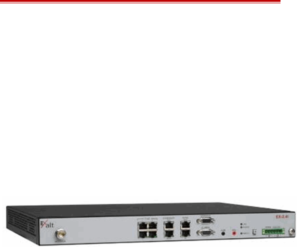
Figure 1 EX-2.4i Digital Microwave Radio
The i-Series radios connect voice and/or digital data from one location to another, obviating the need
for copper or fiber connectivity, or enhancing existing connectivity by providing a redundancy
solution, a primary solution, and/or additional capacity.
Customer Care Hotline (USA): (408) 740-3622
Toll-Free Customer Care Hotline (USA): (844) EXALT-01 (392-5801)
Website: www.exaltcom.com
Sales e-mail: sales@exaltcom.com
Customer Care e-mail: support@exaltcom.com
Mailing Address: Exalt Wireless, Inc.
530 Division Street
Campbell, CA 95008
USA

Exalt Installation and Management Guide
EX-i Series (TDD) Digital Microwave Radios
2206501-019
2016-05-24
The following models of radios are covered in this manual:
• EX-2.4i, 10/100 Ethernet + 4xT1/E1
– Configured for 100Mbps + 4xT1/E1 (32MHz/Mode2)
– With license-key upgrade for 200Mbps capacity (64MHz/Mode2)
– With license-key upgrade for FIPS-197 compliant 128-bit or 256-bit AES encryption
•EX-2.4i Lite, 10/100 Ethernet + 4xT1/E1
– Configured for 27Mbps (8MHz/Mode2 and 16MHz/Mode1)
– With license-key upgrade for 55Mbps
– With license-key upgrade for 100Mbps
– With license-key upgrade for 2xT1/E1
– With license-key upgrade for 4xT1/E1
– With license-key upgrade for FIPS-197 compliant 128-bit or 256-bit AES encryption
•EX-2.4i-16 (or EX-2.4i-16 K, exclusively for Korea), 10/100 Ethernet + 16xT1/E1
– Configured for 4xT1/E1, 100Mbps (32MHz/Mode2)
– With license-key upgrade for 8xT1/E1, 100Mbps (32MHz/Mode2)
– With license-key upgrade for 12xT1/E1, 100Mbps (32MHz/Mode2)
– With license-key upgrade for 16xT1/E1, 200Mbps (64MHz/Mode2)
– With license-key upgrade for FIPS-197 compliant 128-bit or 256-bit AES encryption
• EX-4.9i, 10/100 Ethernet + 4xT1/E1
– Configured for 2xT1/E1, 27Mbps (10MHz/Mode2, 20MHz/Mode1)
– With license-key upgrade for 4xT1/E1, 55Mbps (20MHz/Mode2)
– With license-key upgrade for FIPS-197 compliant 128-bit or 256-bit AES encryption
• EX-5i, 10/100 Ethernet + 4xT1/E1
– Configured for 100Mbps (32MHz/Mode2)
– With license-key upgrade for 200Mbps capacity (64MHz/Mode2)
– With license-key upgrade for FIPS-197 compliant 128-bit or 256-bit AES encryption
•EX-5i Lite, 10/100 Ethernet + 4xT1/E1
– Configured for 27Mbps (8MHz/Mode2 and 16MHz/Mode1)
– With license-key upgrade for 55Mbps
– With license-key upgrade for 100Mbps
– With license-key upgrade for 2xT1/E1
– With license-key upgrade for 4xT1/E1
– With license-key upgrade for FIPS-197 compliant 128-bit or 256-bit AES encryption
•EX-5i-DS3 10/100 Ethernet + 1xDS3 + 16xT1/E1
– Configured for 100Mbps + 4xT1/E1 (32MHz/Mode2)

Exalt Installation and Management Guide
EX-i Series (TDD) Digital Microwave Radios
206501-019 3
2016-05-24
– With license-key upgrade for 200Mbps + 16xT1/E1 (64MHz/Mode2)
– With license-key upgrade for 200Mbps + 1xDS3 (64MHz/Mode2)
– With license-key upgrade for FIPS-197 compliant 128-bit or 256-bit AES encryption
•EX-5i-16 (or EX-5i-16 K, exclusively for Korea), 10/100 Ethernet + 16xT1/E1
– Configured for 4xT1/E1, 100Mbps (32MHz/Mode2)
– With license-key upgrade for 8xT1/E1, 100Mbps (32MHz/Mode2)
– With license-key upgrade for 12xT1/E1, 100Mbps (32MHz/Mode2)
– With license-key upgrade for 16xT1/E1, 200Mbps (64MHz/Mode2)
– With license-key upgrade for FIPS-197 compliant 128-bit or 256-bit AES encryption
Generally, the i-Series models require a clear line-of-sight and proper path clearance to achieve a high-
performance, reliable connection. Perform professional path engineering and site planning BEFORE
installing this equipment.
The primary focus of this document is the installation and maintenance of the digital microwave radio,
and assumes that path engineering and site planning were already performed.
The EX-2.4i models utilize radio frequencies in the range of 2400 to 2483.5MHz. The EX-5i models
utilize radio frequencies in the range of 5250 to 5850 MHz. In most countries these frequency bands
are considered as ‘license-exempt’ or ‘unlicensed.’ This means that virtually any user may use these
frequencies freely, without paying for access, or any type of pre-notification, post-notification or
registration. As a result of this designation, users may also move or change these systems at any time,
with significant flexibility to the location, orientation and configuration of the system. However, also
due to this designation, there may be uncontrolled interference from other similar devices occupying
this spectrum. In these cases, it is up to engineering and maintenance personnel to design the system
with existing and future interference sources in mind, recognizing that there is a chance that the
interference conditions could be very dynamic, and outages may occur on the system as a result, and
that, in some very rare cases, the system may cause interference into another system and may be
required to be disengaged or modified/re-oriented to eliminate the interference.
If the spectrum in your country is designated as ‘license-exempt’ or similar, this does not infer that the
installer may configure the system in any manner at any location. In most cases, there are regulations,
or device-based conditions that limit the use of the device, such as maximum gain antenna, antenna
types and maximum output power, as well as, in some cases, application limits, limited geography of
use, and other unique regulations. The link design engineer and/or professional installer must
determine these limitations and engineer/install the system within the confines of all local regulations.
Also, it is required to examine any regulations that may apply to peripheral equipment, installation and
cabling of the system that may be regulated for human safety, electrical code, air-traffic control, and
other safety-related categories.
In certain countries, the spectrum for this product is NOT considered to be license-exempt. In these
cases, there may be additional regulatory requirements concerning the location, frequency, power,
orientation, configuration, and other aspects of the system, including, in some cases, a need for link
registration, coordination, and fees that may apply to the system usage. Please consult your local
regulatory organization(s) to determine usage requirements.
The EX-4.9i utilizes frequencies in the 4940–4990MHz range, and is typically a licensed band
reserved for use by Public Safety agencies and applications.
In almost all cases, either for license-exempt or other designation, the product itself must be authorized
for use in your country. Either Exalt or Exalt’s agent must have applied for certification or
Exalt Installation and Management Guide
EX-i Series (TDD) Digital Microwave Radios
4206501-019
2016-05-24
authorization to allow the sale and deployment of the system within the country. It is also possible that
only certain versions or configurations of the device are allowed within a particular country. Please
contact Exalt or your authorized Exalt representative for information pertaining to your country.
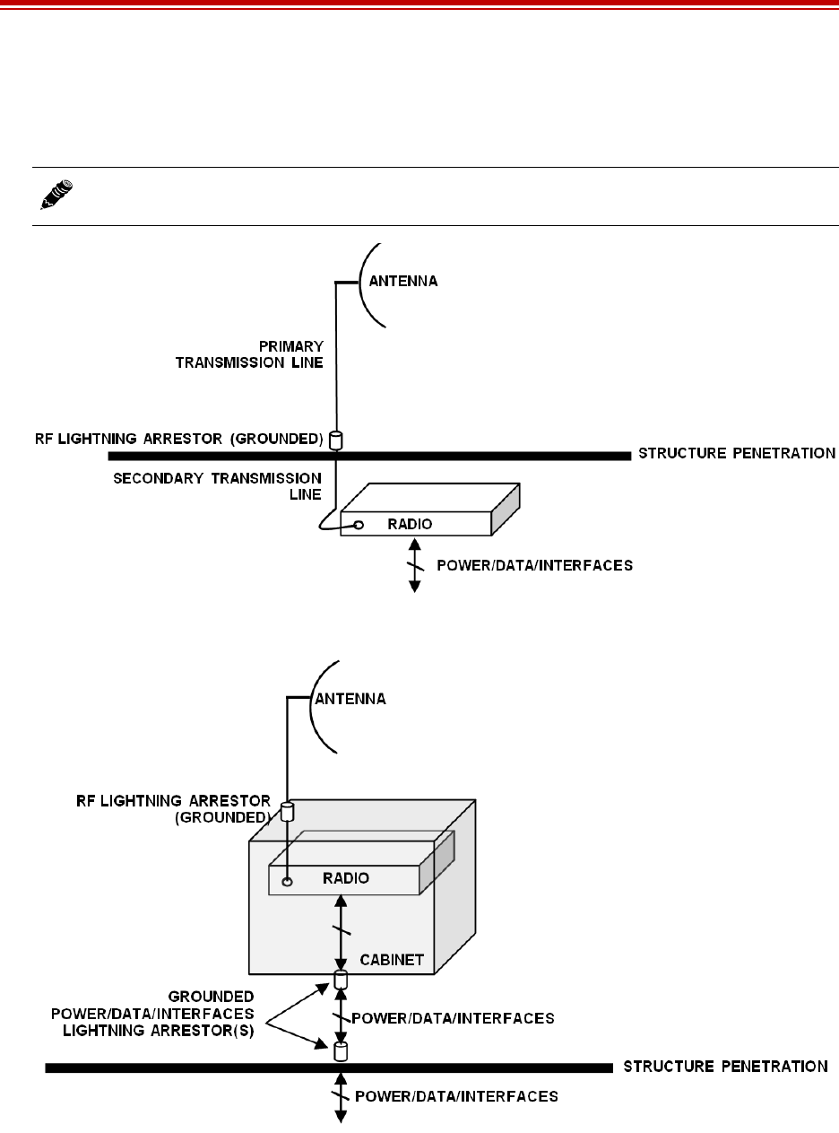
Figure 2 Indoor mount interconnection
Figure 3 Enclosure mount interconnection
For highest performance and reliability, it is advised to minimize the length of RF cable and associated
transmission system losses between the antenna and the radio's antenna port.
Depending on model, combinations of the following data communication interfaces are provided:
Note: It is the professional installer’s responsibility to ensure that the radio system is
implemented in a legal fashion. Exalt is not liable for any unsafe or illegal installations.

Exalt Installation and Management Guide
EX-i Series (TDD) Digital Microwave Radios
206501-019 5
2016-05-24
•10/100BaseT Ethernet
•Up to 16xT1/E1 interfaces for synchronous voice traffic (number of TDM interfaces is determined
by specific model and license-key configuration)
•Up to 1xDS-3 interface for synchronous voice traffic
The i-Series radios feature a wide-mouth direct DC connection (24V or 48V), and are also provided
with an external AC adapter.
All models provide the following primary features and benefits:
•Low-latency optimization and control for voice and data connections
•Very high throughput and flexible interface configurations with voice+data combinations
•Encryption for extreme wireless security
•Easy-to-use management and configuration
•Flexible utilized channel bandwidth selection for interference avoidance and frequency
coordination
•Flexible center frequency tuning for interference avoidance and frequency coordination

Exalt Installation and Management Guide
EX-i Series (TDD) Digital Microwave Radios
6206501-019
2016-05-24
Pre-installation Tasks
This section describes the steps necessary to prepare a site for the installation of the Exalt Digital
Microwave Radio.
Link Engineering and Site Planning
Design all terrestrial wireless links prior to purchase and installation. Generally, professional wireless
engineering personnel are engaged to determine the viability and requirements for a well-engineered
link to meet the users’ needs for performance and reliability.
The reader is referred to the Exalt document, Guidance for Engineering and Site Planning of
Terrestrial Wireless Links. This document and calculator aid in the pre-planning and engineering
required to determine following attributes:
•Antenna type/gain at each end of the link
•Antenna mounting height/location for proper path clearance
•Antenna polarization orientation
•RF cabling type, length, connectors, route, and mounting
•Antenna system grounding
•Lightning arrestor type(s), location(s), and grounding
•Radio mounting location and mechanisms
•Radio grounding
•Radio transmitter output power setting
•Anticipated received signal level (RSL) at each end
•Anticipated fade margin and availability performance at each end
•Radio settings for TDD frame length and occupied bandwidth
•Anticipated throughput performance (TDM circuit support and Ethernet)
•Anticipated system latency
With respect to radio path and site planning, these radios are generally identical to other microwave
terrestrial wireless systems. Engineering of these systems requires specific knowledge about the
radios, including:
•RF specifications (transmitter output power, receiver threshold, occupied channel bandwidth, and
carrier-to-interference tolerance)
•Regulatory limitations on transmitter output power setting and antenna type/gain
•Noise/interference profile for the intended location
Familiarization with the i-Series Radios
The Exalt i-Series radios utilize time division duplex (TDD) radio transmission. This means that the
transmitted signal in both directions uses the same center frequency and transmits in one direction for
a period of time, and then in the opposite direction for another period of time. This total period of time
is referred to as the frame length or TDD frame length, and is further discussed in Time Division
Duplex (TDD) Factors.

Exalt Installation and Management Guide
EX-i Series (TDD) Digital Microwave Radios
206501-019 7
2016-05-24
The two radio terminals are identical hardware, except for the TDD setting in software. When the
radios are in their default state, both radios are configured as Radio B. One end of the link must be
configured as Radio A before the two ends of the radio system can communicate.
It can be considered that Radio A is the primary radio in the link. Radio A provides the master clock
and control to Radio B. For most applications, it is not important how the radio link is oriented, only
that one end is configured for Radio A and the other for Radio B. For some applications (such as,
multi-radio hub sites or repeaters), the orientation of the radio systems may be more critical. See Link
Orientation and Synchronization.
There are three ways to configure the radios for Radio A/B determination:
1Use the Exalt browser-based graphical user interface (GUI) – preferred.
2Use the Command Line Interface (CLI) through Telnet on the AUX port or a Serial connection to
the Console port.
3Use the front panel DIP switch, in case of emergency (EX-2.4i-16 model only).
Exalt recommends using the Exalt GUI for radio configuration. This interface requires a computer
with an Ethernet port and web browser software, such as Microsoft Internet Explorer 5.0 or above. See
Configuration and Management for details on how to connect to and use the browser-based GUI
interface.
-16 and -DS3 models: The front panel DIP switch provides a fast temporary means for Radio A/
Radio B configuration. EX-5i-16 and EX-5i-DS3 models may also require installation of the
Regulatory Domain Key prior to DIP switch operation. See DIP Switch Settings (-16 Models Only).
Shipping Box Contents
Unless purchased as a spare terminal, the radios are shipped as a complete hop (that is, a radio link pair
consisting of two terminals). An outer box has labeling that indicates the contents of the box, with the
part number and serial number details for both radio terminals.
Inside the outer box are two identical boxes, each of these boxes is also marked with the part number
and serial number of the individual terminal contained inside the box. The terminal box contains the
following items:
•Radio terminal (configured as Radio B)
•AC adapter
•Accessory kit
– Rack mount flanges
– Flange mounting hardware (4 x M4 screws; 4 x M4 wave washers)
– DC power connector (1)
– Grounding hardware (1 x M5 screw; 1 x M5 wave washer; 2 x M5 flat washers)
•Registration card
•Quick-start guide
Note: Models with the Access Security management feature ignore DIP switch configurations
after any reset. See the Access Security Page.

Exalt Installation and Management Guide
EX-i Series (TDD) Digital Microwave Radios
8206501-019
2016-05-24
Inspect the outer packaging and the contents of the boxes upon receipt. If you suspect any shipping
damage or issues with the contents, contact Exalt Customer Care.
Initial Configuration and Back-to-Back Bench Test
Every Exalt digital microwave radio goes through extensive quality testing and performance
evaluation over the full operating temperature range prior to shipment. However, before installation, it
is strongly advised to perform several tests and tasks that are much more difficult to perform once the
radio link endpoints are distant from one another. A back-to-back bench test and pre-configuration will
provide confidence that the radio link is operational and properly configured prior to installation, so
that if troubleshooting is necessary, the radio hardware and configuration settings are eliminated from
the troubleshooting process. Verify the following in the back-to-back testing:
•Confirm that the radio system is generally operational
– Radios power-up with planned power and wiring solutions
– Regulatory Domain Key (RDK) entry successful
– RF link connects in both directions
– Traffic passes across the link
•Configure connected equipment and cabling
– Test Ethernet (CAT5) cabling, and/or T1/E1 cabling, any auxiliary connector cabling and
configure all interfaces
– Configure IP settings for configuration and management
– Configure passwords and security modes
– Become familiar with the configuration and management interfaces through the Exalt GUI
interface
– Configure radio parameters, including installing any optional software license keys and
configuring features controlled by license keys
– Set transmitter output power to engineered or allowed level (see RF Output Power Setting)
– Set operating center frequency
Note: Register your system as soon as possible. A 2-year Warranty period applies to products
registered within 90 days of purchase. The Warranty period is reduced to 1-year for
unregistered products and products registered after the first 90 days. See Exalt Limited
Hardware Warranty.
Note: Exalt radios with the RDK function are DISABLED when initially shipped. To
ENABLE the radio, a valid RDK must be entered on the Administration Settings Page of the
Exalt GUI. The RDK references the unit's serial number and is provided based on the country
and/or region where the radio system will be deployed. The RDK is obtained through your
Exalt Authorized distributor or reseller.
Note: Some countries require Dynamic Frequency Selection (DFS), which delays the
transmitter turn-on time during the initial Clear Channel Assessment period of 1 minute. In
accordance with these regulations, the radios boot up, and then wait for 1 minute before
linking.

Exalt Installation and Management Guide
EX-i Series (TDD) Digital Microwave Radios
206501-019 9
2016-05-24
– Set link distance, occupied channel bandwidth, and frame length
•Make detailed radio performance measurements
– Measure transmitter output power
– Measure receiver threshold performance
– Confirm unfaded error-free performance
Some of these tasks may not be possible or practical within a bench test environment due to the nature
of the remote connectivity of peripheral equipment. However, it is good practice to perform as much as
possible in this environment to minimize field/installation time and troubleshooting efforts.
Detailed performance measurements are usually not required for pre-installation, but can be easily
performed at this stage and may be helpful for later troubleshooting efforts or for internal records.
During troubleshooting, there may often be a point at which a back-to-back bench test should be
performed to verify many or all of the above items, and in the case of a suspected faulty device, to help
confirm the fault and determine which end of the system is at fault and in need of repair or
replacement.
RF Output Power Setting
The maximum RF output power is bounded by one of the following criteria:
•Maximum RF output power setting capability of the radio device
•Maximum RF output power allowed/authorized by the local government regulations and for this
specific device
•Maximum effective isotropic radiated power (EIRP) of the transmission system allowed/
authorized by the local government regulations and for this specific device
•Desired RSL to not exceed the maximum RSL allowed by the device
•Desired RSL to minimize/eliminate interference into neighboring systems
1
Time Division Duplex (TDD) Factors
The i-Series radios are very dynamic, allowing the installer to optimize and control the performance of
the radio system for the intended application. The following parameters must be carefully determined
during the link engineering phase:
•Link distance
•Bandwidth
•TDD frame size
•Mode (modulation)
The setting of the above parameters determines the following performance factors:
•Number of supported T1/E1/DS3 channels
•Ethernet throughput
Note: See Back-to-back Bench Testing for detailed instructions.
Exalt Installation and Management Guide
EX-i Series (TDD) Digital Microwave Radios
10 206501-019
2016-05-24
•System latency (delay)
The following generalizations can be made with regards to these factors:
•The shorter the TDD frame size, the lower the latency
•The shorter the link distance, the lower the latency, the higher the throughput
•The longer the TDD frame size, the higher the throughput
•The higher the bandwidth, the higher the capacity
•The higher the mode, the higher the capacity
Link Orientation and Synchronization
Link orientation refers to the Radio A and Radio B placement in your network. Link synchronization
refers to using external or internal timing to coordinate multiple links.
For every link, one end of the radio link must be configured as Radio A, while the other end is
configured as Radio B. In single-link systems, it does not matter which end of the system is mounted at
which end of the link, and there is typically no requirement for any link synchronization.
Link orientation and synchronization are more important for networks with site(s) where there is more
than one link of the same type or for sites using the same type of radio that are very close to each
another at one or both ends.
Configure collocated radio terminals for the same link orientation. That is, configure all radios at the
same location as Radio A or Radio B.
It can be advantageous to utilize link synchronization for collocated links. The radios allow the use of
an optional GPS synchronization kit. This synchronization controls the transmitter and receiver frame
timing so that collocated radios are transmitting at the same time and receiving at the same time. This
can substantially reduce the opportunity for self-interference. Without synchronization, collocated
radios may be transmitting and receiving at the same time, incurring near-end interference.
Note: Disable all T1/E1/DS3 ports if there are no T1/E1/DS3 interfaces connected. This
shifts all available throughput to the Ethernet interface.
Note: If a selected combination of the Link Distance, Frame Size, Bandwidth, and Mode
parameters cannot support all the desired TDM ports, the ports that cannot be supported are
automatically disabled. Priority is placed on the DS3 port, and then the T1/E1 port number.
That is, the first port to be disabled, if necessary, is the highest T1/E1 port number, such as
Port 4 for the standard models, and Port 16 for -16 or -DS3 models (assuming that the DS3
and/or all 16 TDM interfaces are licensed for use). See T1/E1 Configuration Pages for more
information.
Note: It is not always necessary to synchronize collocated radios. If antennas are substantially
separated or blocked from one another and/or frequency separation tuning is used, the
opportunity for near-end interference can be eliminated.
Note: The GPS sync feature is not available on all models. Contact your Exalt Wireless
representative for details.

Exalt Installation and Management Guide
EX-i Series (TDD) Digital Microwave Radios
206501-019 11
2016-05-24
Radio A/B Configuration
Use the Exalt GUI to configure the radio terminals for Radio A and Radio B orientation. Since many
other parameters also need to be set, and the Exalt GUI is needed for these configurations, this is the
best way to completely configure the radio terminals.
Radios arrive from manufacture in default configuration, orientated as Radio B and configured as
shown in Table 1.
DIP Switch Configuration (-16 and -DS3 Models only)
The -16 and -DS3 models have a DIP switch to allow temporary configuration for Radio A and Radio
B. See DIP Switch Settings (-16 Models Only) for information on DIP switch functions.
Table 1 Factory default settings
Parameter EX-2.4i EX-4.9i EX-5i
Frequency 2441 MHz 4965 MHz 5788 MHz; 5600 or 5785 MHz if the
regulatory domain does not allow 5788
MHz
Transmit Power +7dBm +4dBm +4dBm
Bandwidth 8MHz 10MHz 8MHz; 10MHz for some regulatory
domains
Mode Mode 1
Link Distance <10 miles
TDD Frame Size 2ms
Link Security Key 000000000000
Administration Password password
User Passworda
a. Some firmware releases use passwords of admin and user instead of the global password.
password
IP Address 10.0.0.1
IP Mask 255.0.0.0
IP Gateway 0.0.0.0
Ethernet Interfaces MAIN: Alarm Enabled, 100/Full; AUX: Alarm Disabled, 100/Full
AUX port NMS Access In-Band
T1/E1 Settings All Enabled, T1, B8ZS, AIS
Note: In many cases, the system design will not be identical to the factory default
configuration, and in some cases, these differences prohibit the installation of the radio. If at
all possible, obtain a computer and configure the radio terminals using the browser-based
GUI. See Exalt Graphical User Interface (GUI).
Note: Models with the Access Security management feature ignore DIP switch configurations
after any reset. See the Access Security Page.
Exalt Installation and Management Guide
EX-i Series (TDD) Digital Microwave Radios
12 206501-019
2016-05-24
Radio Synchronization
The radio synchronization feature improves the performance of Exalt radios operating in the same
frequency band and that are collocated (such as in repeater and hub configurations). Radio
synchronization ties radio systems together to operate off of a common clock system, ensuring that all
radios simultaneously transmit and receive, and thus eliminating near-field interference issues and
related radio system coupling.
Synchronization Modes
Synchronization can be accomplished using either an internal or external source. In either case, one
radio in the network must be defined as the primary sync source (A) radio.
A Global Positioning System (GPS) kit from Exalt is required to implement external source
synchronization. GPS synchronization is not available on all radio models. Contact your Exalt
representative for details.
Synchronization implementation only requires one synchronization source for any interconnected
network. The system also implements a redundancy configuration to maintain a majority of the
synchronization functions in case of primary radio failure.
For internal synchronization, the primary radio is designated SYNC SOURCE. This radio provides the
master timing for all interconnected radios. SYNC SOURCE radios and collocated radios must be
configured as Radio A.
Collocated radios must be in SYNC RECIPIENT mode; they receive sync signaling from the SYNC
SOURCE, either directly or daisy-chained with other collocated radios. Alternatively, the radio(s) can
be placed in AUTO SYNC mode. AUTO SYNC synchronizes the radios to any source provided on the
SYNC IN port. However, if an appropriate synchronization signal is unavailable, the radio becomes
the SYNC SOURCE for all connected radios.
Internal Synchronization
Figure 4 illustrates the basic interconnectivity of a radio system using internal synchronization. In this
scenario, there are two radios collocated at one site.
Figure 4 Basic radio interconnectivity using internal synchronization
In Figure 5, there are three collocated radios. In this configuration it may be desirable to make one
radio a secondary sync source using AUTO SYNC. This provides redundancy if the primary sync
source radio (A) loses power or experiences any other failure.
Note: The synchronization function is not currently available on all Exalt radio models. A
firmware upgrade may be required for models without sync if sync is desired. Contact your
Exalt representative for details.
Exalt Installation and Management Guide
EX-i Series (TDD) Digital Microwave Radios
206501-019 13
2016-05-24
Figure 5 Collocated radios, one in AUTO SYNC mode to provide redundancy
The synchronization function can be carried across links to additional collocation sites. For example,
Figure 6 illustrates a multi-link backbone with two hub sites.
Figure 6 Multiple-link site configuration, using AUTO SYNC for redundancy
Virtually any combination of hubs and repeater sites, star configurations, and/or backbones can be
implemented with synchronization using these configurations. It is typically necessary or ideal in each
configuration to match the following parameters on every radio in the network:
•Link Distance – Match to the longest distance link in the network.
•Frame Length – Match to the lowest frame length to optimize total system latency (for example,
for TDM networks) or match to a highest frame length to optimize user throughput. Choose an
intermediate value to compromise between latency and throughput.
•Mode – It is desirable, but not always necessary, to match the mode for all collocated links.
•Bandwidth – It is desirable, but not always necessary, to match the bandwidth for all collocated
links.
For complex networks, an Exalt engineer should review multi-link networks before deployment as
several factors can optimize the network for desired performance.
External Synchronization
Use an external GPS source as an alternative to the internal synchronization source for system
synchronization. This is ideal for links that are nearby each other, but are not directly collocated at the
Note: Currently, the configuration shown in Figure 6 is not supported in all models. Consult
your Exalt representative for details.
Exalt Installation and Management Guide
EX-i Series (TDD) Digital Microwave Radios
14 206501-019
2016-05-24
same site. Figure 7 illustrates using a GPS source for the primary synchronization at a typical site with
collated radios.
Figure 7 GPS as primary sync source using AUTO SYNC
Figure 8 illustrates two separate radio locations benefiting from synchronized GPS sources.
Figure 8 Synchronized GPS sources using AUTO SYNC
Offset Timing
Manual control of offset timing is also allowed. This provides a means to delay the synchronization
signal using a user-defined offset. This is helpful when Exalt radios are near other devices operating in
the same frequency band that also use a timing source, such as GPS. The timing source to the Exalt
radios can be adjusted to match the other radio system timing source mechanism.
Offset timing can also optimize timing intervals for repeaters and backbones. As the distance of each
link results in a unique factor for speed-of-light transmission of the radio signal, a subsequent radio can
be delayed in timing so that the overall synchronization of radios is precisely maintained.
Offset timing can be adjusted in 1-ms intervals, from zero to the radio’s frame length setting. For
example, if using a 2-ms frame length, the offset timing can be set from zero up to 1999 ms.
Note: When GPS Sync is enabled, link initiation typically takes 1 to 3 minutes to allow for
the radio to properly synchronize to the available GPS satellites.

Exalt Installation and Management Guide
EX-i Series (TDD) Digital Microwave Radios
206501-019 15
2016-05-24
When Sync is Lost
If the primary sync source (for example, the sync source radio or GPS source) signal is lost due to
equipment failure, a disconnected sync cable, or other conditions, the first radio in the daisy-chain
configuration set to AUTO SYNC resumes the sync function for the remaining connected radios.
If a radio is configured as SYNC RECIPIENT, transmission ceases if the sync signal does not appear
at the SYNC IN connector.
A radio running in AUTO SYNC (without the sync source) is said to be flywheeling. That is, the clock
is free-running off internal clocking and is no longer synchronized to any source.
If the original sync source is restored to the flywheeling radio configuration, the flywheeling radio
attempts to synchronize to this signal without causing transmission interruption. All interconnected
radios receiving sync from the flywheeling radio also continue to operate without interruption.
When the flywheeling radio runs independently for long periods of time, the synchronization signal
can be too far outside of the capture range of the synchronization loop, and portions of transmission
frames can be lost during the re-synchronization process. This condition is temporary and all
interconnected radios re-synchronize to the sync source, as necessary.
For GPS synchronization, the wiring inside the Exalt radio carries the GPS signal to the next radio
cabled in the system, even when power is removed from the SYNC SOURCE radio or during radio
failures. This provides redundancy for catastrophic failure of the SYNC SOURCE and maintains GPS
synchronization. If the GPS source is lost (for example, due to failure of the GPS unit, a disconnected
cable, or satellite blockage), the AUTO SYNC radio resumes synchronization duties for all collocated
radios.
LEDs
There are two LEDs on both the SYNC OUT and SYNC IN ports. Table 3 describes the two SYNC IN
and two SYNC OUT LEDs.
Virtual Local Area Network (VLAN)
VLAN segments information in a single connection and creates multiple separate connections to
secure information of one type or for one set of users from other information types or for other sets of
users. Exalt’s VLAN communications implementation adheres to the IEEE standard 802.1q.
In most cases, an Exalt radio acting as a Layer 2 bridge between two locations is only required to pass
traffic with VLAN tagging. Without additional configuration, all Exalt radios support frame sizes in
excess of 1900 bytes, which currently supports all defined VLAN packet sizes.
Some situations require Exalt radios to act upon VLAN traffic and perform any or all of the following
functions:
•Connect specific traffic, using VLAN tagging, to a specific port on the radio, such as management
traffic to the AUX port.
Note: Offset timing is not supported in all models at the time of this writing. Consult your
Exalt representative for details.
Note: If an application only requires the transparent passing of VLAN traffic, disable the
VLAN function.

Exalt Installation and Management Guide
EX-i Series (TDD) Digital Microwave Radios
16 206501-019
2016-05-24
•Allow only traffic with specifically assigned VLANs to pass across the link, blocking all other
VLANs or any non-VLAN traffic.
•Allow management access only through a VLAN connection, leaving the main traffic transparent.
•Allow management access without a VLAN connection, but flowing only specific VLAN traffic
across the link.
Link Symmetry
The default configuration of i-Series radios provides 50/50 symmetrical throughput. The Tx/Rx
Throughput Ratio setting enables programming different symmetry for applications where
significantly higher throughput in one direction is anticipated such as for video broadcast, video
aggregation, or remote server/storage WANs.
Exalt does not recommend placing two links with asymmetry back-to-back in a serial configuration
due to the TDD cycle of the radios. This configuration requires that one radio transmits in an
overlapping time period while another radio is receiving. Physical antenna isolation and/or frequency
channel spacing may accommodate this configuration. Asymmetry is, however, ideal for single-hop,
multi-link hub/spoke architectures, or simply single independent links.
TDD frame sizes of 2ms and 5ms are supported. The 5ms configuration maximizes the aggregate
throughput of the radio for every situation. The 2ms configuration reduces latency to meet latency-
critical applications, especially for multi-link and TDM circuit support. The following RF BW/mode
combinations are supported for these two configurations:
•16MHz/Mode1
•16MHz/Mode2
•32MHz/Mode1
•32MHz/Mode2
•64MHz/Mode1 (64MHz requires a license key)
The following Tx/Rx ratios are supported for these two configurations:
•65/35 and 35/65
•80/20 and 20/80
For example, a radio configuration of 32MHz/Mode2 with a 5ms TDD frame size supports up to
110Mbps user capacity or 55Mbps full-duplex. By selecting 80/20 on one side of the link and 20/80 on
the other side, the radio allows up to 88Mbps in one direction, and 22Mbps in the opposite direction.
T1/E1 is supported with asymmetric settings. However, based on the BW/mode setting (and in some
cases, TDD frame size and distance), the direction with the limited throughput limits the number of T1
or E1 connections obtained. For example, the 16MHz/Mode1 setting typically supports up to 27Mbps
aggregate throughput. In the 80/20 ratio configuration, one direction is limited to 5.4Mbps, which is
less than 3xE1 and less than 4xT1. Since TDM connections must be symmetrical, this setting therefore
limits throughput to no more than 2xE1 or 3xT1.
Note: Asymmetry is only supported for a specific subset of system configurations that are
optimized for typical asymmetric applications.
Note: Internal and GPS sync is supported with asymmetric settings, but in addition to the
other requirements for sync, all radios tied to sync must be set with matching ratios.

Exalt Installation and Management Guide
EX-i Series (TDD) Digital Microwave Radios
206501-019 17
2016-05-24
Simple Network Management Protocol (SNMP)
The Exalt radios primarily use a browser-based graphical user interface (GUI) for radio configuration
and management, as described in Exalt Graphical User Interface (GUI). In addition, a command line
interface (CLI) is provided for serial and/or Telnet access, as described in Command Line Interface
(CLI). SNMP is often used for management of larger networks as described here. Use SNMP to
manage networked devices and execute the following functions:
•GET: Obtain information from the device, such as a configuration setting or parameter.
•SET: Change a configuration setting on the device.
•TRAP: The device proactively informs the management station of a change of state, usually used
for critical alarms or warnings.
One feature of the SNMP implementation is that system configuration changes do not take effect using
the SET command. Instead, groups of configuration settings can be preconfigured for global change,
and a single 'Save' (Commit) command implements all changes.
When some parameters are changed, a link may drop and/or management control lost. MIB files allow
many parameters to be set at once, allowing only a temporarily dropped link or management control
issue. The opposite end radio can be quickly reconfigured, with little downtime for the link and
management control. The save (Commit) command is similar to the Update button.
Dropped links or management control issues do not occur with every parameter change. Many
configuration changes do not impact traffic or management access.
Exalt radios utilize SNMPv3, a high security version of SNMP, to ensure secure access to and storing
of management data. The SNMPv3 security string matches the admin and user passwords. Passwords
must be eight characters or longer.
Some Exalt radio models also allow for “legacy” SNMP support for SNMPv1 and SNMPv2.
Configuration of all passwords and community strings is performed from a separate Simple Network
Management Protocol (SNMP) Configuration page.
Exalt Installation and Management Guide
EX-i Series (TDD) Digital Microwave Radios
18 206501-019
2016-05-24
System Installation and Initiation Process
The tasks required for radio installation and initiation are outlined in the following figure.
Figure 9 Radio installation tasks
Path & Site
Analysis
Link Design
Build Antenna
Structures &
Egress
Mount
Antennas &
Transmission
Line
Install & Test
Network &
Power Wiring
Read This
Manual
Completely
Pre-configure
Radios
Perform
Back-to-Back
Test
Mount Radios
Connect
Transmission
Line
Connect
Power
Align
Antennas to
Planned RSL
Verify LEDs
for Good Link
Test Network
Connectivity
Connect &
Test Primary
Services
Test Network
Management
System
Both Transmission
System & Radio
Preparation Tasks
Must Be Complete
Transmission System Tasks Radio Preparation Tasks

Exalt Installation and Management Guide
EX-i Series (TDD) Digital Microwave Radios
206501-019 19
2016-05-24
Record Keeping
After installation, record the following items for ongoing maintenance and future troubleshooting.
Keep a record for each end of the radio link and store a copy of these records at the radio location, at
the opposite end radio location, and a central record storage location.
•GPS coordinates for antenna locations at each site
•Antenna heights above ground level (AGL), as mounted
•Antenna model numbers, serial numbers, and specifications
•Antenna polarization as mounted
•Length/type of primary transmission lines at each site
•Model number and serial number of RF lightning arrestors
•Length/type of secondary transmission line(s)
•Transmitter output power setting as installed at each site
•RSL as measured after antenna alignment at each site
•Designed RSL per original design at each site
•RSL reading with far-end power off (from each end)
•Spectrum analyzer plot with far end off at each site
•Voltage standing wave ratio (VSWR)/return loss at radio’s antenna connector at each site
•Radio’s network management IP address at each site
•Radio’s network management gateway address at each site
•Radio’s operating frequency, bandwidth setting, and mode of operation
•Optionally purchased extended warranty and/or emergency service contract details
In addition, certain information may be desired for central record-keeping only:
•Link security codes and log in passwords (stored in a secure place)
•Photographs of complete installation
•End-user sign-off/acceptance documentation (if any)
•Photo of product identification label (part number, serial number, MAC address information)
•Electronic copy of radio’s configuration file
•Electronic copy of radio’s installed software

Exalt Installation and Management Guide
EX-i Series (TDD) Digital Microwave Radios
20 206501-019
2016-05-24
Installation
This section presents all tasks required to install the Exalt Digital Microwave Radio.
Mechanical Configuration and Mounting
The i-Series radios are one-piece designs intended for deployment in a telecom equipment rack indoors
or in an appropriate environmental enclosure. The device must be deployed within an ambient
temperature range as specified, and properly ventilated with no obstructions to the air intake and
exhaust. The standard models occupy 1 rack unit (1RU = 1.75"/4.5cm) height in a typical telecom rack.
The -16 and -DS3 models occupy 1.5 RU (2.625"/6.7cm).
In most cases, additional racked equipment can be placed directly above and/or below the device with
no empty spaces in the rack. However, depending on power consumption and ventilation for adjoining
devices, they may pass heat to the device, not allowing the radio to cool properly and increasing the risk
of malfunction. Heat dissipation from the radio may also affect adjoining devices. Provide air space
above and below the device, where possible. If not possible, a thermal analysis may be required by a
professional engineer to determine the impact of thermal transfer between all adjoining units.
Provide proper clearance for all cables and connectors attached to the device. Notably, the RF cable
connector may require significant clearance for the bend radius of the coaxial cable assembly. Use a
properly specified 90º RF connector to minimize clearance requirements, which may be necessary in
enclosure implementations. All RF connectors, cables, and adapters must be rated for operation within
the radio’s frequency range (2400–2483.5 MHz for EX-2.4i; 4940–4990 MHz for EX-4.9i; 5250–5850
MHz for EX-5i). RF connector losses must be accounted for within the link engineering design and
output power settings.
Rack Mounting
Rack mounting hardware for a standard 19" (48cm) rack is included in the accessory kit. Attach the rack
mounting brackets to the sides of the unit with the provided screws. The radio can be mounted in one
of four configurations:
•Front flush mount (front panel even with the rack mounting surface)
Figure 10 Front flush mount configuration
•Front projection mount (front panel extended forward from the rack mounting surface)
Figure 11 Front projection mount configuration
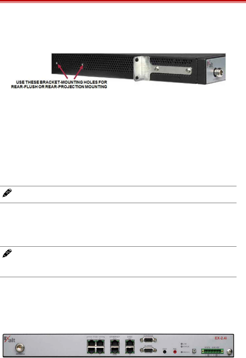
Exalt Installation and Management Guide
EX-i Series (TDD) Digital Microwave Radios
206501-019 21
2016-05-24
•Rear flush mount (rear panel even with the rack mounting surface)
•Rear projection mount (rear panel extended forward from the rack mounting surface)
Figure 12 Rear-mount locations
The rack mounting brackets accommodate identical mounting configurations as shown in the previous
figures, and can be mounted three different ways with respect to the vertical orientation in the rack:
1Projecting down, using one full rack space and half of the space below, and leaving a half-space
gap below.
2Projecting up, using one full rack space and half of the space above, and leaving a half-space gap
above.
3Centered within two spaces, with ¼ rack space gap above and below.
Two radios mounted in the same rack can be mounted in adjoining spaces, utilizing a total of three rack
spaces.
Table or Rack Shelf Mounting the System
Affix rubber feet or adhesive-backed non-slip pads (not included) near the corners of the unit along the
bottom panel when mounting on a table or a rack shelf. These pads help keep the radio stable on a
wooden or metal surface.
Radio Ports and Indicators
This section provides a brief overview of the connectors, controls, and indicators on the device. Details
about each item are in other sections of this document.
The EX-2.4i front panel is shown in Figure 13. The EX-4.9i and EX-5i front panel are identical to the
EX-2.4i model, except for the model number shown in the upper-right corner.
Figure 13 Front panel (EX-2.4i, EX-4.9i, or EX-5i)
Note: Screws for attaching the radio to the telecom rack are not provided; use the appropriate
screw type that matches the equipment rack.
In many areas, it is necessary to strap the equipment to a table or rack shelf if mounting in
this manner. In case of earthquake or other shock or vibration, or an accidental pull of a
cable, the unit should be secured from falling. It may also be necessary to secure the AC
adapter, if it is used.
Exalt Installation and Management Guide
EX-i Series (TDD) Digital Microwave Radios
22 206501-019
2016-05-24
The EX-2.4i-16 front panel is shown in Figure 14. The EX-5i-16 front panel is identical, except for the
model number shown in the upper-right corner.
Figure 14 Front panel (EX-2.4i-16 or EX-5i-16)
The EX-5i-DS3 model front panel is shown in Figure 15.
Figure 15 Front panel (EX-5i-DS3)
Connector Overview
The primary user interfaces are shown in Figure 16 provides details of the front panel connectors of the
EX-2.4i EX-4.9i, or EX-5i. Detailed pin structures for each connector are in Interface Connections.
Figure 16 Primary front panel connectors (standard models)
Table 2 Connectors
Label Type Gender Function
Antenna N F Transmission line connection to antenna.
T1/E1 (1–4 or 1–16) RJ-48C F Primary ports for User T1 or E1 circuits to
traverse link.
DS3 (IN/OUT) BNC F Primary ports for User DS3 circuit to traverse
link.
ETHERNET (MAIN/
AUX) RJ-45 F Primary ports for user Ethernet and/or
management data (10BaseT or 100BaseT) to
traverse link.
SYNC (IN/OUT) RJ-45 F Internal or external radio synchronizing source
(for example, GPS) input and output.
CONSOLE 9-pin sub-D F Management port (serial) for PC/PDA for
Command Line Interface (CLI)
communications.
ALARMS 9-pin sub-D F External alarm inputs and outputs.
Exalt Installation and Management Guide
EX-i Series (TDD) Digital Microwave Radios
206501-019 23
2016-05-24
DS3 IN and DS3 OUT connections (Figure 17) may be independently grounded or ungrounded to the
chassis using a small DIP switch between the connectors. Ground loops to connected equipment must
be avoided. Set the DIP switches accordingly.
Figure 17 EX-5i-DS3 connectors and grounding switches
LED Indicators
Table 3 provides details of the LED indicators on all models.
GND (Ground) Bantam F Common (return) volt meter test point for
measuring RSL.
RSL Bantam F Voltmeter test point for measuring received
signal level.
24–48VDC 6-pin modular M DC power input from DC source or AC
adapter.
(Ground) Threaded (M5)
receptacle F Chassis ground connection (M5 x 0.8 threads).
Table 3 LED indicators
Location/Label Type Function
LINK 3-color
LED Indicates RF link status:
Green Solid = Error-free connection (BER<10e-6)
Yellow Solid = Errored connection (10e-3>BER >10e-6)
Red Solid = No link (BER>10e-3)
Red Flash= No remote information available (when RMT is
pressed and held)
Off = Improperly powered or fatal system failure
STATUS 3-color
LED Indicates system status:
Green Solid = No alarm conditions (normal operation)
Yellow Solid = Alarm conditions, not traffic effecting
Yellow Slow Flash = In loopback (from this end)
Yellow Fast Flash = In loopback (at this end)
Red Solid = Alarm conditions; traffic effecting
Red Flash = No remote information available (when RMT is
pressed and held)
Off = Improperly powered or fatal system failure
Table 2 Connectors (Continued)
Label Type Gender Function

Exalt Installation and Management Guide
EX-i Series (TDD) Digital Microwave Radios
24 206501-019
2016-05-24
DS3 3-color
LED Indicates DS3 connection status:
Green Solid = No alarm conditions (normal operation)
Yellow Solid = DS3 signal present, but DS3 is not enabled
Red Solid = DS3 enabled, but not present
Off = DS3 not in use
RADIO A 3-color
LED Indicates radio orientation:
Green Solid = Radio is configured as Radio A, based on software
setting
Off = Radio is configured as Radio B
ETHERNET MAIN/AUX Left Corner Green LED Solid/Flashing = Data present
Off = No data present
ETHERNET MAIN/AUX Right
Corner Green LED Solid = Negotiated @ 100Mbps
Flash = Negotiated @ 10Mbps
Off = No connection negotiated
T1/E1 Left Corner Green LED Solid = Connection present (clocking confirmed)
Fast Flash = Connection present; coding/clock problem
Slow Flash = Connection present, but unexpected
Off = No connection/clock
T1/E1 Right Corner Green LED Solid = In a loopback state
Fast Flash = Automatic indication signal (AIS) is active
Off = No loopback; no AIS activity
RMT (LED inside button) Amber
LED Off = Remote end LINK and STATUS LEDs are both green
Solid = No remote end status available
Flash = Alarm conditions at the remote end (LINK and/or
STATUS LEDs are non-green)
SYNC IN Left Corner Green LED Solid on = GPS is normal (no alarms)
Flash = GPS is in alarm
Off = No GPS source detected
SYNC IN Right Corner Green LED Solid on = Sync locked, no alarms
Flash = Sync signal detected, but not locked
Off = No input sync signals detected
SYNC OUT Left Corner Green LED Solid on = Radio configured as SYNC SOURCE
Flash = Radio configured as AUTO SYNC
Off = Radio configured as SYNC RECIPIENT or sync is
disabled
SYNC OUT Right Corner Green LED Solid on = SYNC SOURCE is external (GPS 1 pps)
Off = SYNC SOURCE is internal
Table 3 LED indicators (Continued)
Location/Label Type Function

Exalt Installation and Management Guide
EX-i Series (TDD) Digital Microwave Radios
206501-019 25
2016-05-24
RMT (Remote) Button
The RMT button is the only external control on the radios. This button allows easy and quick evaluation
of the status of the remote-end radio. When the RMT LED is amber flashes, this is an alert that the
remote end has an alarm condition. Press the RMT button to determine the alarm conditions.
When the RMT button is pressed and held and local LEDs flash, this indicates that no remote-end
information is available. This indicates that the remote radio is either not powered, is booting, or is not
linked in the direction towards the local radio, or the local radio is receiving excessive errors in this
direction. It could also indicate a serious failure of either radio.
Local-end LEDs (when this button is not pressed) in combination with remote-end information (from a
technician located at the far end, and/or when the button is pressed) can substantially aid in rapid
troubleshooting analysis.
Power
The radio requires a DC power source within specifications. The DC can be provided from a DC battery
source, central lab/rack supply, or from the supplied AC adapter.
Terminating the RF Connector
Before applying power, the device’s RF connector must be properly terminated into a 50-Ohm load. If
this is not performed, the radio may be damaged by simply applying power. Also, there are human
safety factors to consider regarding potentially harmful RF radiation.
There are a few simple means to accommodate proper termination:
•Connect a 50-Ohm coaxial termination device to the RF port of the radio. The termination must be
rated to 1W (or more). Example(s) include:
– Broadwave Technologies P/N 552-200-002, or similar
•Connect the complete transmission system. That is, the RF cabling including the antenna. The
cabled antenna provides a proper termination for the RF output.
•Connect a fixed (or a series of fixed) 50-Ohm attenuator(s) to the RF connector, either directly or
at the end of an RF transmission line. The attenuator must be at least 30dB as specified at the
operating frequency (~2400 MHz for the EX-2.4i; ~4950 MHz for the EX-4.9i; ~5700 MHz for
the EX-5i), and rated for a minimum of 1W input power. Examples include:
– Broadwave Technologies P/N 352-103-xxx
(Unmarked LED on rear panel) 2-color
LED
Indicates overall status (from the rear panel):
Green = LINK and STATUS LEDs are both green
Red Flash = LINK and/or STATUS are in a yellow state; no red
states exist
Red Solid = LINK and/or STATUS are in a red state
Off = Improperly powered or fatal system failure
Read this section completely before applying power.
Table 3 LED indicators (Continued)
Location/Label Type Function

Exalt Installation and Management Guide
EX-i Series (TDD) Digital Microwave Radios
26 206501-019
2016-05-24
– Bird 2-A-MFN-xx
– JFW Industries 50FP-xxx-H6-N
AC Power
The AC adapter easily connects to the device. The AC rating of the adapter accepts most standard
voltages and frequencies worldwide. Refer to the input voltage requirements stated on the label affixed
to the adapter to ensure that the adapter can be used with the AC mains supply.
The AC plug outlet provided with the adapter may need to be replaced to match the country
configuration. The adapter cable uses a standard connector for this cable for use of a pre-wired cable
appropriate to the outlet configuration. If the appropriate cable is not available, the existing AC plug
end can be severed and a replacement plug affixed. Consult a qualified electrician for this activity.
Do not plug the adapter into the mains power. First, verify that the RF connector is properly terminated
(see Power), and then plug in the radio-side connector from the AC adapter to the radio. If the AC mains
can be turned off using a switch, disable the power, plug the AC side of the adapter into the AC mains
socket, and then enable power to the circuit. If the AC mains cannot be turned off, plug in to the AC
main socket to apply power.
Verify that the radio is active by observing LED activity. All LEDs on the radio flash at initial power
cycle.
It is strongly encouraged that the AC mains supply be fused or on a separate breaker to ensure against
over-voltage and/or over-current situations and to provide some form of protection to the radio
electronics and other devices connected to the same supply. In addition, if the AC power is subject to
significant spikes or variation, power conditioning is a worthwhile investment, as the quality of mains
power may have a direct impact on the device operation, performance and/or reliability. An
Uninterruptible Power Source (UPS) or other form of battery-backed system protects against brown-out
and black-out conditions, and condition the power presented to the adapter.
Evaluate the opportunity for lightning or other similar surges to be present on the powering system,
including the ability for surges to couple to the power wiring system. If an evaluation indicates that there
is a potential likelihood for these conditions to occur, additional surge protection is recommended for
the input power wiring, especially to protect the radio electronics between the adapter and the radio’s
DC input connector.
The above statement is similarly true for every wired connection to the device. While the configuration
for surge suppression or line conditioning is of a different type for each kind of signal interface, the
opportunity for damage to the device, loss of communications and property is significant. In some cases,
there can also be a risk to human life by not protecting against lightning entering a building through
wiring or improper grounding. If you do not have experience in this type of installation practice, consult
a qualified electrician and/or telecoms professional during the installation and wiring of the equipment.
DC Power
The device accepts DC power within the voltage specifications. For some EX-2.4i terminals, the DC
voltage is 48 volts, nominal. For all other i-Series models, the DC voltage input accepts either 24 volts
or 48 volts, nominal. Ensure that the power source is specified for the proper amount of current delivery
capacity. The DC power may be connected as a positive or negative voltage supply, and be referenced
to ground or ‘floating’ (differential voltage). There are different system grounding considerations
depending on the nature of the DC supply grounding, and consult a qualified electrician or telecoms
professional on the proper wiring and grounding process.
Exalt Installation and Management Guide
EX-i Series (TDD) Digital Microwave Radios
206501-019 27
2016-05-24
To connect a DC source, with the power disabled on the DC supply, connect proper gauge wiring to the
DC supply. For most (short) power cable runs, 18AWG or 24AWG wire can be typically used. Strip the
ends just long enough for enclosure to the DC radio connector (approximately 0.25 inches/6mm). If
using stranded wire, the stripped ends inserted into the DC terminal connector must be solder-tipped. If
using solid wire, a solder tip is not necessary. Ensure that the power wiring is long enough to neatly
traverse, when properly dressed, between the source supply and the radio mounting location. If DC
wires are to be exposed to outdoor environments, use wire in the proper weatherproof wiring jacket.
For longer runs of DC wiring, use a higher gauge wire and/or higher current source supply to overcome
the additional resistance of the DC wiring. However, the DC connector for the radio may not be able to
accept a high diameter wire, transition to thinner gauge near the end of the wiring run or use the
maximum diameter wire for the entire wiring run, as long as it meets the powering requirements
considering total resistance of the wiring and the power source current load capacity.
Insert the wiring ends into the DC mating connector (supplied) and tighten the terminal screws to secure
the wire into the connector. Do not connect the mating connector to the radio system and disable the
power system.
Pay close attention to the polarization of the DC signals coming from the DC supply and the ground
conductor (if any), and ensure that they are connected to the proper pins of the DC mating connector.
The connector mate on the radio is clearly marked on the front panel for proper polarization and for
ground connection.
Wire across the plus (+) and minus (-) terminals from the DC supply. In addition, place a separate
jumper between the proper terminal and the ground terminal to reference one side of the power supply
line to the radio chassis ground. In some cases, the DC system may need to be floating and this ground
jumper is not necessary; however, many configurations require one side to be grounded for proper
electrical safety.
Figure 18 DC connector
Once the wires are connected to the mating connector, do not connect to the radio. First test the DC
connection to the connector from the DC supply. Engage power on the DC supply, and use a volt meter
to verify proper voltage level and polarity.
Verify that the RF connector is properly terminated, as described in Terminating the RF Connector.
Disengage power once again on the DC source, and connect the mating connector to the radio device.
Engage power on the DC source. Verify radio is active by observing LED activity. All LEDs flash
during the initial power cycle to verify that they are operational. Secure the DC connector using the
integral captive screws at each end. This prevents accidental disconnection.
Warning! Consult a qualified electrician if uncertain about how to properly ground the
system and connect power.

Exalt Installation and Management Guide
EX-i Series (TDD) Digital Microwave Radios
28 206501-019
2016-05-24
See Power regarding fusing, breakers, lightning protection, surge protection and power conditioning.
Follow these recommendations for a DC supply.
Reset to Critical Factory Settings
If necessary, the radio terminal may be reset to critical factory settings. This may be necessary if the IP
address and/or passwords for the system are not known. All other configurations are left at their current
settings. If a complete default factory configuration is desired, load the Default Configuration File into
the system, as described in File Activation Page.
The following parameters are configured after a reset to critical factory settings:
•IP Address = 10.0.0.1
•IP Mask = 255.0.0.0
•IP Gateway = 0.0.0.0
•Administration password = password (or ‘admin’1)
•User password = password (or ‘user’1)
•Endpoint Identifier = Radio B (on some models, depending on firmware version and/or DIP switch
position)
•VLAN disabled
•Disabled management interfaces are enabled
To perform a reset to critical factory settings:
1Remove power.
2Remove connections to the ALARMS port.
3Hold the RMT button on the front panel while applying power.
Continue to hold the RMT button through the entire boot cycle (approximately 45 seconds).
The front-panel LEDs toggle during the boot cycle.
4Release the RMT button when LED behavior stabilizes.
Antenna/Transmission System
This section provides guidance to mounting and connecting the RF transmission system, which consists
of the antenna, RF cabling, and RF lightning arrestors. Consult the manufacturer's instructions for
proper mounting, grounding, and wiring of these devices, and for definitive direction. These
manufacturer's instructions supersede any information in this section. See Antennas for a list of
supported antennas.
1. Some firmware versions use the passwords admin and user instead of the global password of password.
Note: Models that have the access security management feature that also have DIP switches
on the front panel ignore DIP switch configurations after any reset. See the Access Security
Page.

Exalt Installation and Management Guide
EX-i Series (TDD) Digital Microwave Radios
206501-019 29
2016-05-24
Initial Antenna Mounting
The antenna must be an exact model recommended by the path and site planning engineer(s). Mount the
antenna at the proper height, mast/mounting location and polarization orientation as determined by the
path and site planning engineer(s). The model type, location, and orientation of the antenna is critical
with respect to achieving proper path clearance, as well as to mitigate external or self- interference from
nearby or collocated systems operating in or near the same frequency band.
The antenna structure must be secure and safe with respect to the mounting of the antenna, transmission
system weight, and the combined weight of any personnel that may climb or attach to the structure. The
combined weight of items and forces on the structure must be carefully considered in the design and
construction of the structure. This must include the weight bearing on the structure in the highest wind
conditions possible in the region, and with respect to all objects affixed to the structure.
If additional objects are affixed to the structure in the future, it may be important to evaluate both the
mechanical impact of these planned additions (with respect to wind and weight loading), as well as the
potential impact to RF interference and frequency coordination (if additional radio equipment is
anticipated). This is especially important if future equipment is likely to operate within the same
frequency band.
Once the antenna is mounted, cabled, and aligned, your goal is to never require modification. This prior
planning is important in the path and site planning stages and in construction of the antenna structure.
Follow the antenna manufacturer’s instructions for mechanical mounting of the antenna. Ensure that
there is enough room around the antenna for alignment activities (moving the antenna in vertical and
horizontal arcs), and for the RF transmission line to connect to the antenna connector unobstructed and
within the specified bend radius requirements of the transmission line.
At this point, the antenna mounts should be fully secure to the structure, the feed of the antenna securely
mounted to the antenna (if the feed is a separate assembly), and the azimuth and elevation adjustments
not completely tightened in preparation of the antenna alignment activity. It is a good practice to
connect the transmission line to the antenna connector as early in the process as possible, to reduce the
opportunity for debris or moisture to enter either the antenna connector or the transmission line
connector. Use a connector cover or other temporary measures to ensure that the connector is kept clear.
Take extra care if the antenna is installed during inclement weather to ensure that no moisture gets inside
the antenna connector at any time.
Now the antenna can be aimed in the general direction required for the link. Use a compass, a reference
bearing, binoculars or any other similar device to point the antenna in the direction (generally) of the
far end radio, and then slightly tighten the azimuth and elevation adjustments so that the antenna
maintains its general position and is safe to be left without additional securing. Refer to the Exalt white
paper, Antenna Alignment, for more information on antenna alignment techniques.
Transmission Line from Antenna to Egress
Most installations use coaxial transmission line for the connection between the antenna and the radio
device. Coaxial transmission line can either have a solid or braided shield. Solid-shield cables are more
resistant to external signal coupling and interference, but are generally stiffer than braided cables.
Warning! Mount the antenna in a restricted area and in a manner preventing long-term
human exposure to the transmitted RF energy. To comply with FCC and Industry Canada
regulations, the minimum safe distance from the antenna for continuous human exposure for
the EX-2.4i models is 10'/3m, 3.3' (1m) for EX-4.9i models, and 10.5'/3.2m for EX-5i
models.

Exalt Installation and Management Guide
EX-i Series (TDD) Digital Microwave Radios
30 206501-019
2016-05-24
Consult the path or site engineer(s) to ensure that the proper materials are chosen for the installation and
that all factors were considered. Refer to the Exalt white paper, Transmission Line for Exalt Indoor
Radio Systems.
Generally, the larger the diameter of the transmission line, the lower the loss. So for longer runs of
transmission line, larger diameter cables are highly advised. However, at every frequency, there is a
maximum diameter cable that supports the operating frequency. Verify the specifications. This is
determined in the path and site planning process.
In some cases, the choice of transmission line is not coaxial cable, but is instead air-dielectric
waveguide. This is an expensive solution and is generally not necessary, but may be required for very
long transmission line runs, and/or very long link distances, and/or for systems requiring extremely high
reliability.
Table 4 lists representative samples of transmission line types recommended for the Exalt Digital
Microwave Radio.
There are several other brands and models of transmission line that are perfectly acceptable. However,
for extremely long transmission lines and/or extremely long radio paths, it may be necessary to use
waveguide transmission line instead of coaxial transmission line. In these cases, waveguide type EW20
is recommended for EX-2.4i models (0.45dB/100ft. loss at 2.4GHz), type EW52 for the EX-4.9i and
EX-5i models (1.2dB/100ft. loss at 5.8GHz, 1.35dB/100ft. loss at 5.3GHz).
It is critical that the transmission line and antenna be capable of supporting the same type of connector,
or easily adapted. It can be important to minimize the number of connectors and adapters, and it is ideal
that they match directly without adaptation. In most cases, transmission line allows for N-type male
connectors and antennas have N-type female connectors. For waveguide, the waveguide flange can
typically accommodate a direct adapter to an N connector, or alternatively, the antenna can be
purchased with a direct waveguide connection. But often a flexible coaxial jumper is required to connect
between the waveguide and antenna, as waveguide is generally inflexible and can be mechanically
challenging to align to the exact antenna connector location.
If possible, connect the primary transmission line directly to the antenna. It is desired to have the fewest
possible pieces of transmission line in the system, to minimize losses and points of failure from
connectors. The antenna can typically accommodate a direct connection if planned in advance. Use a
90º adapter for the connection to the antenna, if necessary, but confirm that all connectors and
transmission lines are properly specified for the operating frequency with minimum loss, proper
impedance (50 Ohm) and proper VSWR characteristics.
Transmission line connector termination is a critical element of the installation. Many ‘factory built’ RF
transmission lines do not provide the proper characteristics for proper transmission, despite their
published specifications, often due to the fully or semi-automated process of factory termination, which
may not have considered the frequency of your system. When buying pre-terminated transmission line,
it is strongly advised to obtain the documentation of test measurements on the connected transmission
Table 4 Recommended transmission line
Manufacturer Type Description Loss at 2.4GHz Loss at 4.9GHz Loss at 5.3GHz Loss at 5.8GHz
Andrew LDF4-50 1/2-inch solid shield 3.3dB/100ft. 5.6dB/100ft. 5.7dB/100ft. 6.0dB/100ft.
Andrew LDF4.5-50 5/8-inch solid shield 2.5dB/100ft. 4.3dB/100ft. 4.4dB/100ft. 4.7dB/100ft.
Times LMR-600 1/2-inch braided shield 4.3dB/100ft. 6.8dB/100ft. 6.9dB/100ft. 7.3dB/100ft.
Times LMR-900 5/8-inch braided shield 2.9dB/100ft. 4.5dB/100ft. 4.6dB/100ft. 4.9dB/100ft.
RFS LCF12-50J 1/2-inch solid shield 3.5dB/100ft. 5.5dB/100ft. 5.6dB/100ft. 5.9dB/100ft.
RFS LCF12-58J 5/8-inch solid shield 2.8dB/100ft. 4.4dB/100ft. 4.5dB/100ft. 4.8dB/100ft.

Exalt Installation and Management Guide
EX-i Series (TDD) Digital Microwave Radios
206501-019 31
2016-05-24
line showing that the loss characteristics and VSWR are within the specified limits specifically at your
operating frequency. In addition to factory-built transmission line, self-terminated transmission line can
suffer the same issues.
The manufacturers of transmission line typically offer instruction and certification for transmission line
termination, and may also provide videos illustrating the process. There is no amount of extra care,
education, precision, and effort that can be overstated for this process.
Once the transmission line is connected to the antenna, traverse the exact route provided by the site
planner. There is often a need for a small excess of transmission line near the antenna to accommodate
both the need for extra slack as the antenna is loosened and moved for the alignment process, and to
accommodate a drip loop for the transmission line and the initial transmission line securing hardware
and grounding near the antenna. In addition, the transmission line is typically very stiff, and can provide
undue pulling force on the antenna connector. Take care to align the cable with the connector so that it
does not provide any torque or strain on the connector.
Consult your transmission line manufacturer for the proper transportation, hoisting, securing, and
grounding process. Always be very mindful of the entire length of transmission line to ensure that the
transmission line is never twisted, kinked, or over-bent beyond the specified bend radius. Once a
transmission line is over-bent or kinked, it will likely never recover its specified characteristics, even
after straightening, and will often be completely unusable.
The opposite end of this primary transmission line typically terminates at the building or enclosure
egress point. This is where to locate the RF lightning arrestor. Ensure that a proper termination to the
connector-type of the lightning arrestor is made at this location. A drip loop may be required and proper
securing hardware and grounding must be accommodated.
As soon as practical, weatherproof the connected ends of the transmission line to the antenna and
lightning arrestor. This process should be delayed as long as possible to ensure that all systems are
working properly before applying the weatherproofing. Once weatherproofing is applied, it may have
to be removed for testing or installation modification. With this in mind, if the installation is occurring
during inclement weather, take extra care at all times to ensure that no moisture enters any connector at
any time. If moisture is suspected to have compromised the antenna or transmission line, it may render
those devices useless without any means for remedy except for full replacement.
Indoor Mounting
On rare occasions the antenna can be mounted indoors behind a window. In these cases, there would
not be a need for drip loops or an RF lightning arrestor. Use a very short transmission line connected
directly between the antenna and the radio mounted nearby. The weatherproofing process can also be
omitted.
RF Lightning Arrestor
RF lightning arrestors provide a direct path to ground for lightning strikes that may couple to or directly
hit the outdoor transmission system or antenna structure. The RF lightning arrestor prevents any
associated voltage and current from entering the building or enclosure, where it might harm the radio
equipment, other equipment, or humans.
The following lightning arrestors are examples of proper devices for Exalt Digital Microwave Radios:
Caution! Always follow the manufacturer’s termination process EXACTLY, and only use
the manufacturer’s authorized tools and connectors for a given transmission line type.

Exalt Installation and Management Guide
EX-i Series (TDD) Digital Microwave Radios
32 206501-019
2016-05-24
•Polyphaser AL-LSXM
•Citel PRC5800
Mount and ground the RF lightning arrestor in accordance to the manufacturer’s recommendations.
Place it as close as possible to the egress point where the next piece of transmission line enters the
building or enclosure. Minimize the distance to the egress to lessen the opportunity for lightning to
couple to or strike the unprotected section of transmission line (if any). Where possible, use a bulkhead
connector to eliminate any opportunity of this risk. Keep cable lengths behind the arrestor and into the
egress substantially short (less than 3'/1m) as a safe practice. Consult a qualified electrician or installer
in all cases of grounding and lightning arrestor implementation.
Transmission Line from Egress to Radio
A single transmission line section from the egress to the radio RF connection is always desired.
Minimize the number of connectors and adapters. For indoor runs, a cable ladder or tray may be needed
to properly secure the cable. In some cases, a short flexible jumper allows ease of connection to the
radio’s RF connector. A properly specified 90º connector can often eliminate this need. An installation
with space around the radio to accommodate a gentle bend radius of the transmission line is also good
for a direct connection. In all cases, ensure that the transmission line is not a pulling force of the RF
connector on the radio. Transmission lines can be very stiff and can damage the connector if not dressed
properly. Also, follow the transmission line manufacturer’s instructions for the proper use of cable
securing devices.
Antenna Alignment
Antennas must be installed at both ends of the planned link to commence precision alignment. Refer to
the Exalt white paper, Antenna Alignment.
Antennas are typically aligned using the radio hardware for precise alignment. However, there are many
very useful tools available to aid in this process, inclusive of devices specifically designed for the
purpose of aligning antennas. Some examples are:
•XL Microwave Path Align-R
•Teletronics 17-402
Use of these devices may be extremely advantageous as compared to using the radio, because they
employ many unique facilities to aid in this process. Using these tools also makes it possible to align
the antennas before the radio equipment is delivered. However, many installers successfully use the
radios as the means for antenna alignment.
There are two primary facilities when using the radio to align the antenna:
•RSL voltage test point using a volt meter (recommended)
The RSL test point DC voltage is inversely proportional and numerically calibrated to the received
signal level. The voltage rises as the antennas are less in alignment, and falls as antennas are more
in alignment. The voltage measurement corresponds to the received signal level in measurements
of dBm (a negative number for RSL measurements). For example, an RSL of -60dBm yields an
RSL voltage measurement of 0.60VDC; an RSL of -45dBm measures 0.45VDC.
•GUI RSL reading indicates the current RSL in dBm.
Alignment of the antennas using the RSL test point can be accomplished in the following ways:
•Radio near or at antenna location

Exalt Installation and Management Guide
EX-i Series (TDD) Digital Microwave Radios
206501-019 33
2016-05-24
– Temporarily connect the radio to the antenna using a short piece of transmission line, so that
the radio is very close to the antenna location
–Run wires, as necessary, from the RSL test point to the volt meter so that the antenna
installer can directly view the volt meter
•Run separate wires from radio mounted location to antenna location
– Temporarily connect a set of wires from the RSL test point to the antenna location, to allow
the radio installer to use a local volt meter
•RF/DC coupler
Install a temporary DC coupling device at the radio antenna port and at the antenna connector.
Connect the RSL test point to the radio antenna port coupler, and the volt meter to the antenna
connector coupler. See DC Coupler for Antenna Alignment for more information
•Verbal relay/walkie-talkie/mobile radio/cell phone
– A person located at the radio front panel can use a short-range communication device or verbal
relay to communicate to the antenna installer and read off RSL voltage measurements
Only use the browser-based GUI for antenna alignment if there is no other means available. If this
method is required, refer to Exalt Graphical User Interface (GUI). The RSL reading can be read on a
PC or any handheld computing device that supports an HTML browser and Ethernet connectivity.
Note: Using this method, the final RSL voltage readings during alignment may be different
(better) than the planned RSL, due to the short RF transmission line. Use the path calculation
tool to determine the RSL that should result in this temporary configuration to ensure proper
ideal alignment.
Note: Due to the resistance of the cable, the RSL readings might be impacted. Use the thickest
wiring possible. Test the impact of the voltage reading due to the wiring by comparing a direct
measurement at the RSL test point as opposed to the end of the wiring.
Note: There is a slight delay in RSL readings in the GUI as the RSL levels change. In this case,
fine alignment can be done in small adjustments allowing a small gap of time so that the impact
of the adjustment on the GUI display catches up to real time.

Exalt Installation and Management Guide
EX-i Series (TDD) Digital Microwave Radios
34 206501-019
2016-05-24
Configuration and Management
This section describes the command line interface (CLI) and Exalt graphical user interface (GUI).
Command Line Interface (CLI)
Exalt Digital Microwave Radios provide a CLI to set key parameters on the system. Use the Console
port for serial devices, or use the Ethernet MAIN or AUX ports for a Telnet session over a network
connection.
Connect to the Radio with a Serial Connection
For serial interface to the CONSOLE port, on your PC, PDA, dumb terminal, or any other device with
a serial interface and text input capabilities, use Hyperterminal or a similar application with the
following settings:
Use a standard straight-through serial cable to connect between most computer serial ports and the
Console port on the radio. A null modem cable is not properly wired for this interface. See Interface
Connections for wiring details.
After establishing the serial connection, press ENTER to display the login prompt.
Telnet into the Command Line Interface (CLI)
Use a Telnet connection to access the CLI in the Exalt Digital Microwave Radios. Use the CLI to set
key parameters on the system.
Connect to the Radio in a Telnet Session
Make the Telnet connection to the radio through the Ethernet port. Use Windows and perform the
following steps:
1Open a command prompt or MS-DOS prompt (Start>Run).
2Type C:\>Telnet <IP Address> at the command line:
The default IP address is 10.0.0.1
Use Telnet when prompted to enter the administration level login and password. The default
administration login is admin and password is password. It is recommended that the default
administration password be reset by performing a radio reset (see Reset to Critical Factory Settings).
Bits per second: 9600
Data bits: 8
Parity: None
Stop bits: 1
Flow Control: None
Note: The accessing computer must be on the same IP subnet as the radio. If the radio
supports DHCP and DHCP is enabled (see Ethernet Interface Configuration Page), which is
the default setting for a radio shipped from Exalt (for the models with this feature), and your
computer’s Ethernet port is set for DHCP addressing, the radio will configure your computer
to an IP address value which is either 2 or 10 higher than the radio’s current IP address (for
example, if the radio is set to 10.0.0.1, the computer will be set to 10.0.0.3 or 10.0.0.11,
depending on the radio model and the software version running on the radio).
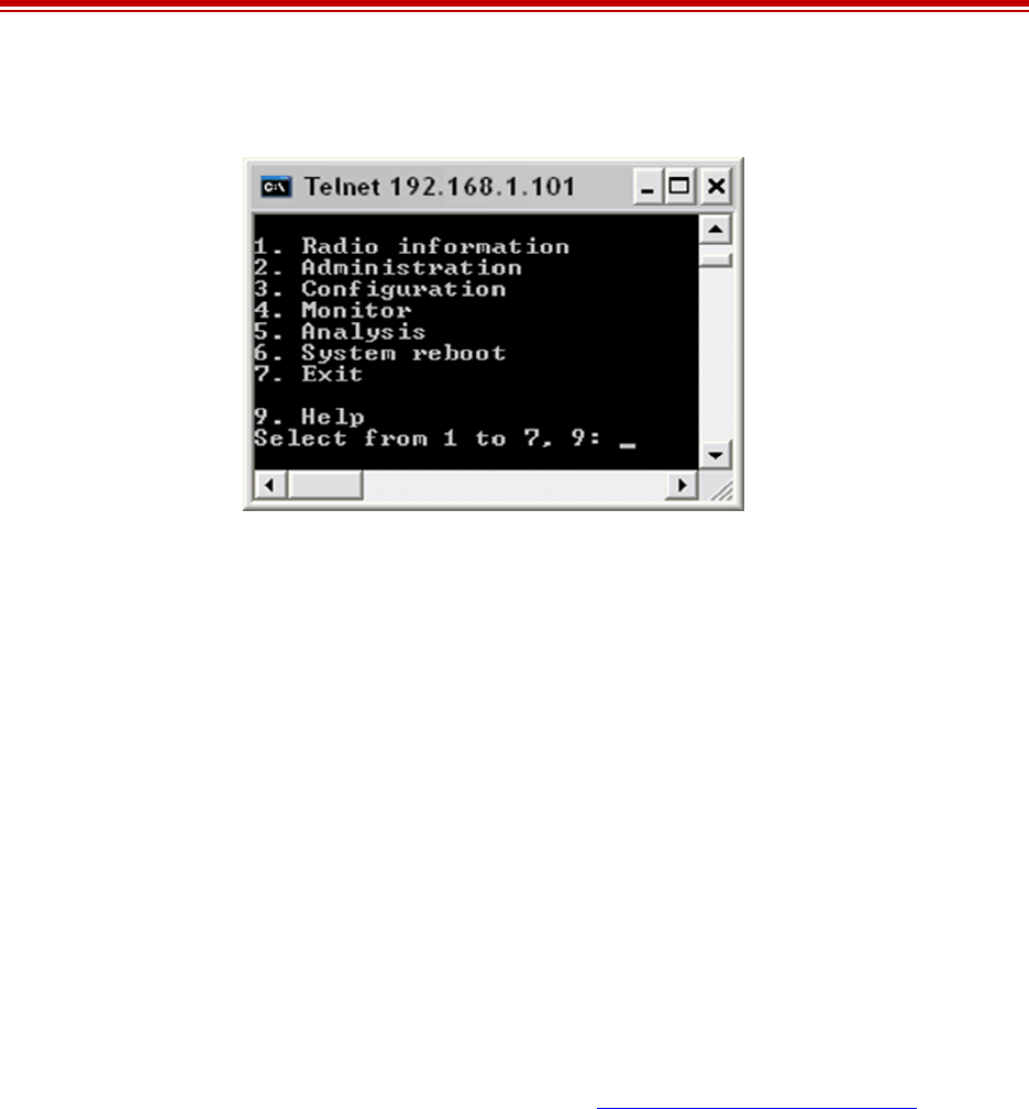
Exalt Installation and Management Guide
EX-i Series (TDD) Digital Microwave Radios
206501-019 35
2016-05-24
Figure 19 shows the menu choices available after log in.
Figure 19 CLI root menu
The following selections can be made on all screens:
•0 = back to previous screen
•9 = help
•Ctrl+\ (control and backslash keys) = exit session
Exalt Graphical User Interface (GUI)
The Exalt GUI is the primary user interface for configuring and troubleshooting the radio and radio
system. A computer or hand-held device with a conventional HTML browser and Ethernet port is
required. Microsoft Internet Explorer is the preferred browser. Netscape, Mozilla, and Firefox are also
supported.
Preparing to Connect
If the radios are new, both radios are preconfigured as Radio B, and have the same IP address. The
initial priority is to configure one radio to Radio A and assign different IP addresses, unique to each
radio. There are two ways to change the IP address:
1Reset the radio to the critical default factory settings (see Reset to Critical Factory Settings).
2Connect to the GUI using the default IP address (10.0.0.1), and change the IP address through the
GUI interface.
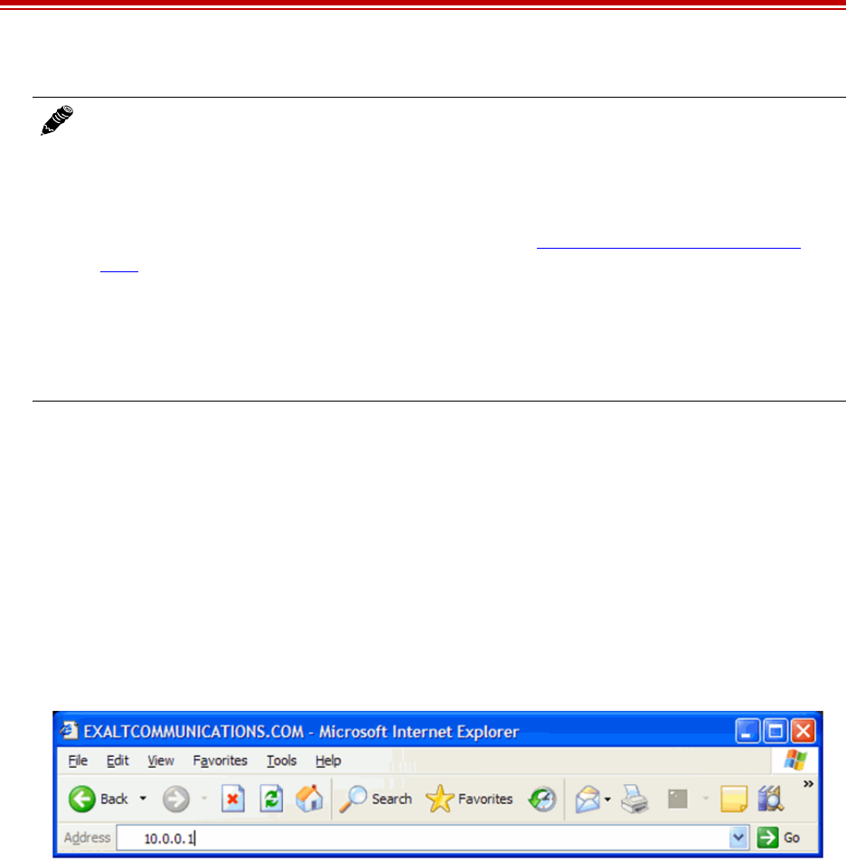
Exalt Installation and Management Guide
EX-i Series (TDD) Digital Microwave Radios
36 206501-019
2016-05-24
To configure a radio as Radio A, connect to the GUI and change the configuration, as discussed in this
section.
Log In
Use the following steps to log in to the Exalt GUI.
1Open a browser window.
Microsoft Internet Explorer is the recommended browser. Netscape, Mozilla, and Firefox are also
supported. If there are issues with your browser, please report it to Exalt Customer Care. You may
be required to use a different browser to immediately overcome issues.
2Type the IP address of the radio in the address bar.
Figure 20 Initiating the browser connection
The following window displays after pressing the Enter key or clicking the Go button in the
browser window.
Note: To connect to the radio’s Ethernet port and use the GUI interface, the accessing
computer must match the radio’s IP address subnet. It is therefore necessary to either change
the radio’s IP address through the CLI to match the subnet of the computer, or change the
computer’s IP address to match the subnet of the radio (such as, a computer IP address of
10.0.0.10 if trying to connect to a radio set to the factory default IP address of 10.0.0.1).
If the radio supports DHCP and DHCP is enabled (see Ethernet Interface Configuration
Page), which is the default setting for a radio shipped from Exalt (for the models with this
feature), and your computer’s Ethernet port is set for DHCP addressing, the radio will
configure your computer to an IP address value which is either 2 or 10 higher than the radio’s
current IP address (for example, if the radio is set to 10.0.0.1, the computer will be set to
10.0.0.3 or 10.0.0.11, depending on the radio model and the software version running on the
radio).
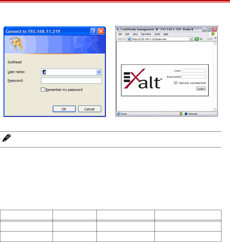
Exalt Installation and Management Guide
EX-i Series (TDD) Digital Microwave Radios
206501-019 37
2016-05-24
Figure 21 Browser Login screens–model dependent
Login Privileges
There are two levels of login privileges:
•Administrator (admin) – assigned complete permissions to view, edit, and configure
•User (user) – assigned limited, view-only permissions with no edit or configuration rights
The default login names and passwords are as follows:
Administrator login credentials are required for configuration purposes. Type the user name and
passwords for Administrator level and click OK. The following screen displays.
Note: Some models support SSL/SSH secure browser management, and display the login
screen on the right. Browser security can be enabled or disabled for these models.
Table 5 Default login information
Privilege level User name Default password Alternate passworda
a. Early firmware versions use the alternate passwords.
Administrator admin password Admin
User user password User
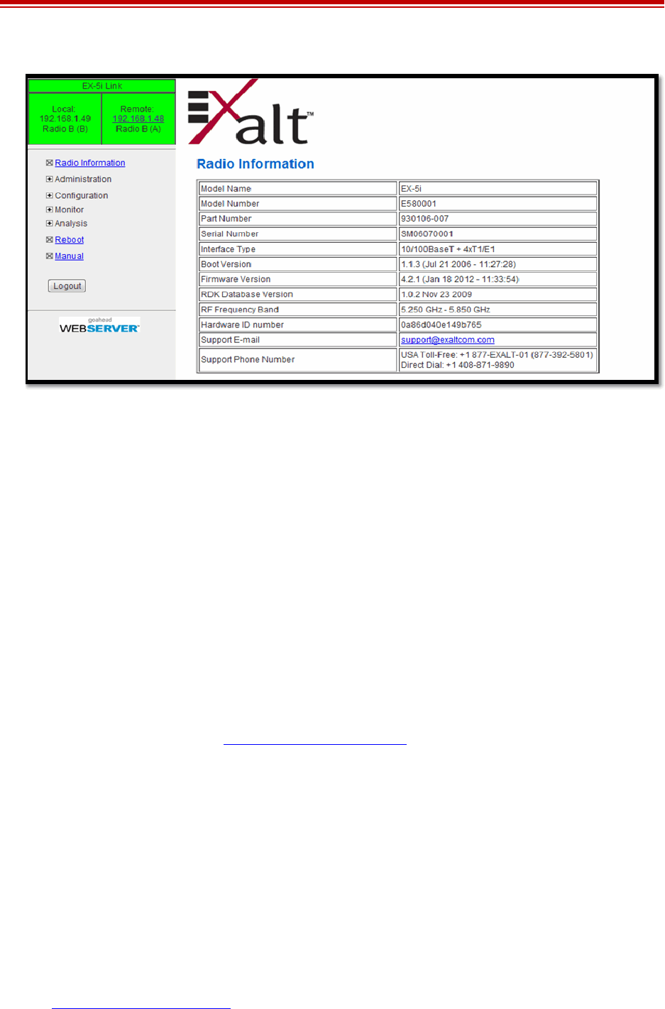
Exalt Installation and Management Guide
EX-i Series (TDD) Digital Microwave Radios
38 206501-019
2016-05-24
Figure 22 Radio Information page
Quick Start
To establish a link on the bench, apply the following basic configurations to the radio terminal. Use the
steps in the Quick Start Guide included with the radio. A summary of the items that need to be
configured are:
•Radio IP address for each end.
– Each end must have a different IP address and cannot match the accessing computer’s IP
address or any address assigned if radios are part of a larger network.
– It may be required to change the IP address of the accessing computer after changing the IP
address of the radio so that the IP subnet matches.
– The radio IP address is listed on the Administration Settings page.
•Install the Regulatory Domain Key (RDK) for RDK-enabled radios only.
– The radio is non-functional without the RDK.
– RDK is entered on the Administration Settings Page.
– RDK references the unit’s serial number and the country/region where the radio will be
deployed.
– RDK is obtained through your Exalt Authorized reseller or distributor.
•Set one radio as Radio A.
– The radio selected as Radio A must be configured.
– Radio A/B selection is the Endpoint Identifier parameter on the System Configuration page.
– Even though both radios are set as Radio B by default, confirm this configuration on the radio
intended to be Radio B.
If all other parameters are still configured at their factory default settings, the radios can now be
connected back-to-back to verify that the link is communicating and perform any other desired tests.
See Back-to-back Bench Testing for test information.
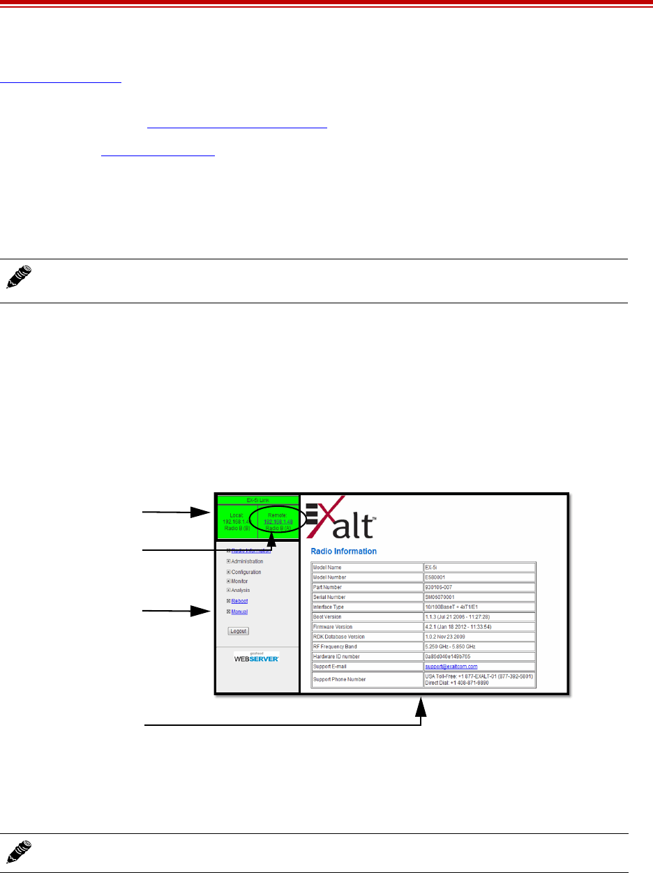
Exalt Installation and Management Guide
EX-i Series (TDD) Digital Microwave Radios
206501-019 39
2016-05-24
Navigating the GUI describes each page of the GUI. Most configuration parameter settings are
intuitive. The following link parameters must match at both ends for the link to communicate:
•Link Security Key (Administration Settings Page)
•Bandwidth (File Transfer Page)
•RF Frequency (System Configuration page)
•Link Distance (System Configuration page)
•TDD Frame Size (System Configuration page)
Navigating the GUI
The GUI provides the primary interface for all configuration and management. There are three sections
of the main GUI window:
•Summary status information section (upper-left corner)
•Navigation panel
•Main window
Figure 23 Exalt GUI window description
Summary Status Section
This section of the Exalt GUI provides a review of the system status.
In the screens in Figure 23, the top bar illustrates the alarm condition of the link. The information
inside the bar is equivalent to the entry of the Link Name set by the administrator in the Administration
Settings page.
The color of the panel indicates alarm status:
•Green indicates the system is communicating and all functions are normal
Note: Changing any of these parameters causes a temporary loss of link. The GUI displays a
warning and provides an opportunity to cancel changes.
Note: Click the radio IP address link to access that radio for management.
SUMMARY STATUS
NAVIGATION PANE
MAIN WINDOW
LINK TO
REMOTE RADIO
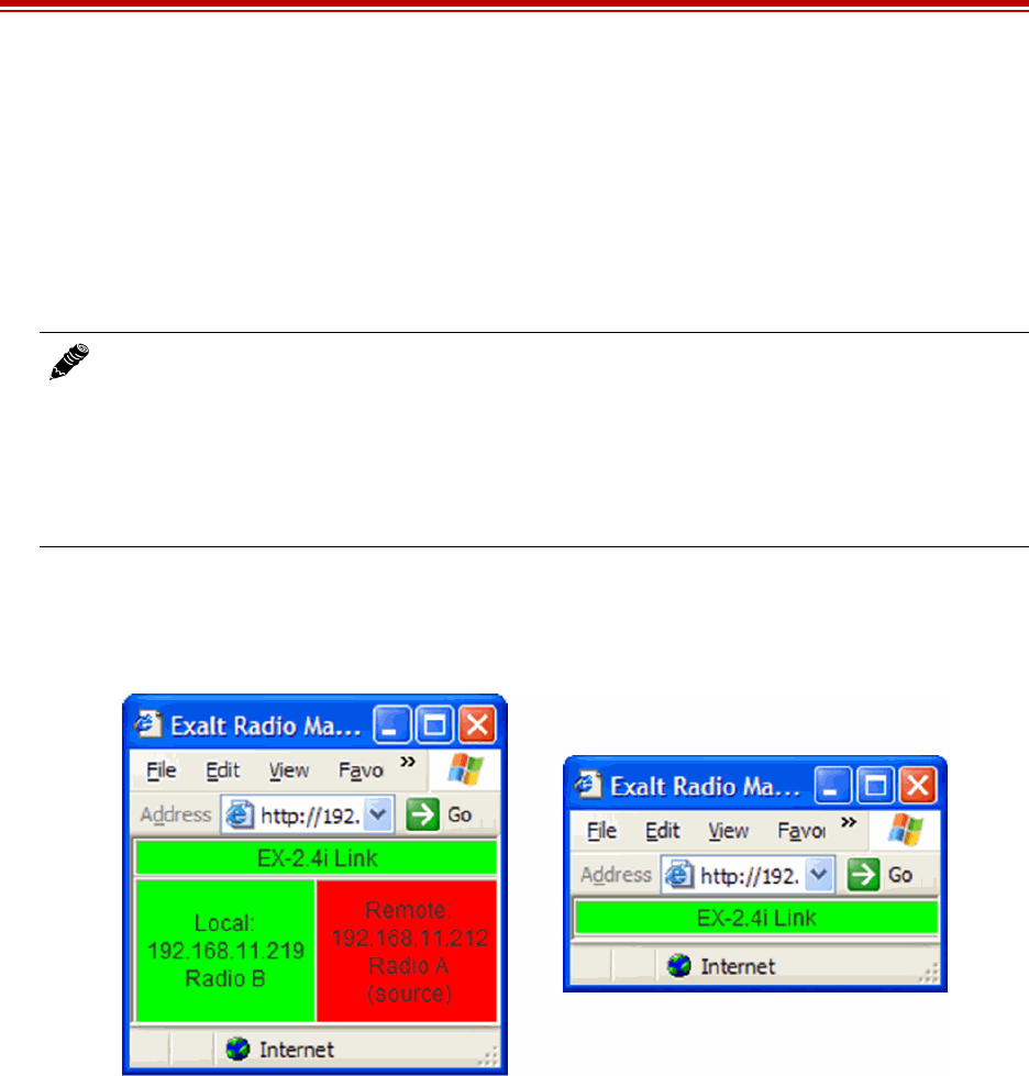
Exalt Installation and Management Guide
EX-i Series (TDD) Digital Microwave Radios
40 206501-019
2016-05-24
•Yellow indicates a minor non-traffic affecting alarm condition
•Red indicates a major traffic affecting alarm condition
The left panel summarizes the alarm conditions of the local radio (the radio that matches the IP
address). The information displayed is the IP address and the endpoint identifier (Radio A or Radio B).
The right panel summarizes the alarm conditions of the remote radio (the radio linked to the local
radio).
The Summary Status Section allows the Exalt GUI to be a rudimentary management system. Minimize
the browser window to display just the top bar or the top bar and radio information, and open several
browsers on the desktop. When a window status changes to yellow or red, you can quickly maximize
that window to determine the issues.
Figure 24 Summary status information
Navigation Panel
In the navigation panel, pages with sub-pages have a plus (+) to the left of the page link. Click the plus
sign or page name title to view sub-page titles. The pages can be collapsed to hide the sub-pages when
a minus (–) sign appears to the left of the page link.
Management pages are indicated with an X to the left of the page name. Click the X or page name to
display the page within the main window.
Note: The ‘local’ radio might be the near-end or the far-end radio, depending on the
management interface connection. The terms local and remote refer to the orientation of the
radio terminals relative to the IP address you are managing. When making certain changes to
a near-end radio without first making changes to the far-end radio, the link may become
disconnected unless configuration changes are reverted to their original settings. When
making changes that may disrupt the link, always change the far-end radio first, and then the
near-end radio to match.

Exalt Installation and Management Guide
EX-i Series (TDD) Digital Microwave Radios
206501-019 41
2016-05-24
Note: The ‘local’ radio might be the near-end or the far-end radio, depending on the
management interface connection. The terms local and remote refer to the orientation of the
radio terminals relative to the IP address you are managing. When making certain changes to
a near-end radio without first making changes to the far-end radio, the link may become
disconnected unless configuration changes are reverted to their original settings. When
making changes that may disrupt the link, always change the far-end radio first, and then the
near-end radio to match.
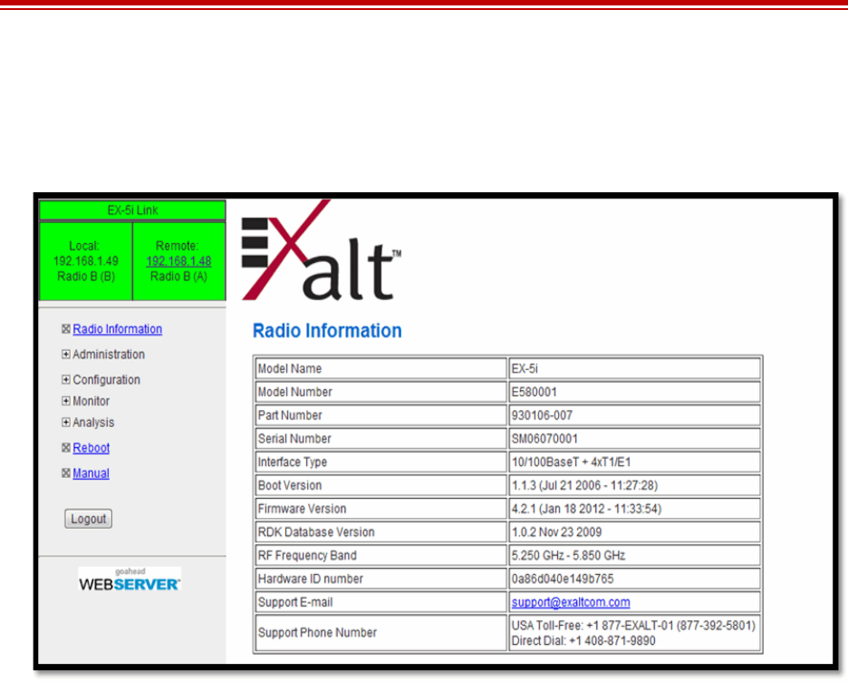
Exalt Installation and Management Guide
EX-i Series (TDD) Digital Microwave Radios
42 206501-019
2016-05-24
Radio Information Page
This page provides general information about the local radio terminal. This information is helpful for
troubleshooting and for record keeping.
Figure 25 Radio Information page
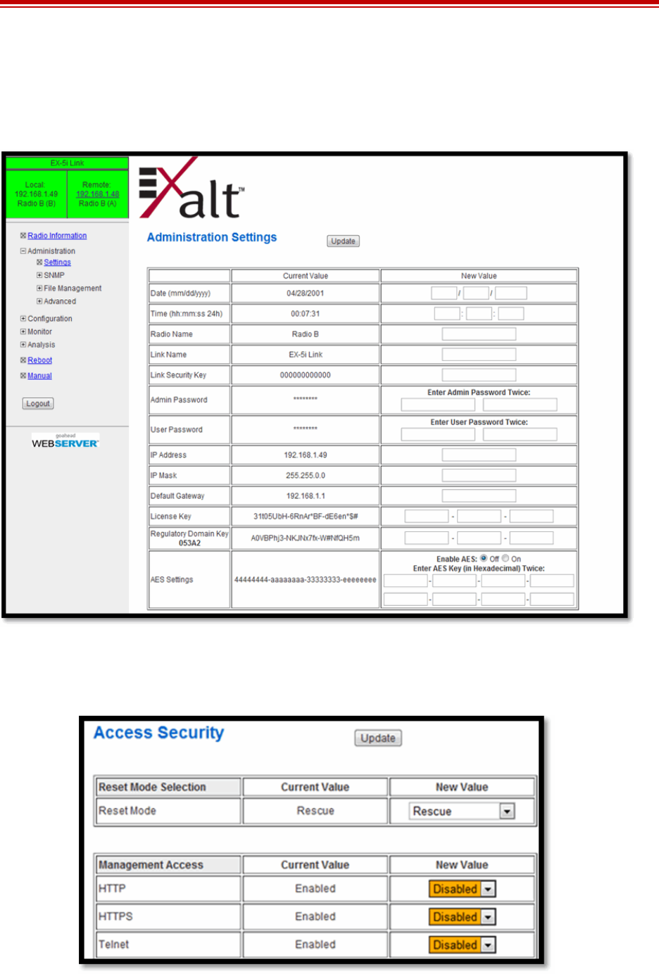
Exalt Installation and Management Guide
EX-i Series (TDD) Digital Microwave Radios
206501-019 43
2016-05-24
Administration Settings Page
This page allows contains general parameters for the radio system. The Current Value column lists
entries actual settings. Desired changes are entered in the New Value column.
Figure 26 Administration Settings page
As shown in Figure 27, on all pages changed fields display with an orange background. After all
desired changes are entered, click the Update button to accept and enable changes.
Figure 27 Changed fields and Update button

Exalt Installation and Management Guide
EX-i Series (TDD) Digital Microwave Radios
44 206501-019
2016-05-24
Most entries on this page are self-explanatory. The following lists unique or important parameters.
•Fill in the date and time fields as soon as practical. Events are captured with time/date stamps,
which is valuable information for troubleshooting.
•Set the Link Security Key to something other than the factory default setting (12 characters, all
zeros) at each end. The link security key must match at both sides of the link. If the security key
remains at the factory setting, the radio link is open to sabotage by a party with the same radio
model. Each link should have a unique security key. If using the same security key for every link
in the network, the radio could link to any other radio with the same security key. This is
problematic in multi-radio networks.
– Note that the security key must be exactly 12 characters. Any alphanumeric character can be
used. The link security key is case sensitive.
•Reset the admin and user passwords. These passwords should not match. If the admin password
remains at the factory default setting, it provides an opportunity for random reassignment by a
network-connected user.
– The new password must be entered twice. If the passwords do not match and the Update
button clicked, the password is not changed and remains set to the previous password.
•Enter the license key provided by Exalt to access extended features or diagnostic capabilities.
Click Update to accept the changes and enable the new features. License keys are issued by radio
serial number, so ensure that the license key used was issued for this particular radio.
•The Regulatory Domain Key establishes the frequency bands, tuning frequencies, bandwidths,
output power and Dynamic Frequency Selection (DFS) requirements, in accordance with the
regulations that apply in the country where the product is deployed. The RDK must be typed in to
enable ANY functionality for the radio. The RDK is issued to the Exalt Authorized distributor or
reseller, and is paired to the specific serial number of the radio.
•AES (Advance Encryption Standard) can be implemented to provide additional data security for
the wireless link. This function requires an upgrade license key (purchased separately). Both
radios in the link must have a valid AES upgrade license key to implement AES. Different bit-
length encryption license keys (for example, 128-bit and 256-bit) are also available, depending on
model type. If the required upgrade license key is present, simply insert a matching hexadecimal
string on both terminals and select the Enable AES On option for AES encryption. Note that
similar to the administration and user passwords, the AES string must be entered twice for each
terminal.
Note: Changing the link security key interrupts transmission until the opposite end is
changed to match. Always change the far-end radio first, and then change the near-end radio.
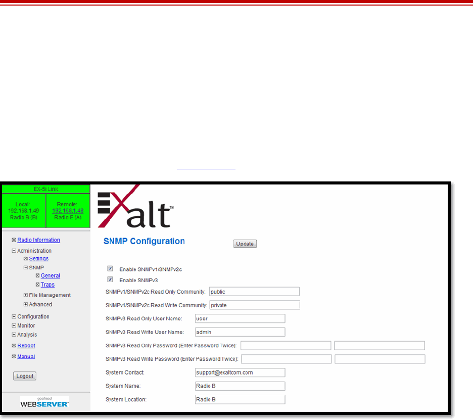
Exalt Installation and Management Guide
EX-i Series (TDD) Digital Microwave Radios
206501-019 45
2016-05-24
Simple Network Management Protocol (SNMP) Configuration
This page allows the enabling and disabling of the Simple Network Management Protocol (SNMP)
functions. Use SNMP to manage networked devices and execute the following functions:
•GET: Obtain information from the device, such as a configuration setting or parameter.
•SET: Change a configuration setting on the device.
•TRAP: The device proactively informs the management station of a change of state, usually used
for critical alarms or warnings. See SNMP Traps.
Figure 28 SNMP Configuration page
One feature of the SNMP implementation is that system configuration changes do not take effect using
the SET command. Instead, groups of configuration settings can be preconfigured for global change,
and a single ‘Save’ (Commit) command implements all changes.
When some parameters are changed, a link may drop and/or management control lost. MIB files allow
many parameters to be set at once, allowing only a temporarily dropped link or management control
issue. The opposite end radio can be quickly reconfigured, with little downtime for the link and
management control. The save (Commit) command is similar to the Update button.
Dropped links or management control issues do not occur with every parameter change. Many
configuration changes do not impact traffic or management access.
EX-i Series (TDD) utilize SNMPv3, a high security version of SNMP, to ensure secure access to and
storing of management data. The SNMPv3 security string matches the admin and user passwords.
Passwords must be eight characters or longer.
The SNMP MIBs are organized similar to the GUI. Become familiar with the GUI before using the
SNMP function.
SNMP v1/v2c/v3 Support Options
Enable the SNMPv1/v2c options to allow entering read and read/write community strings.
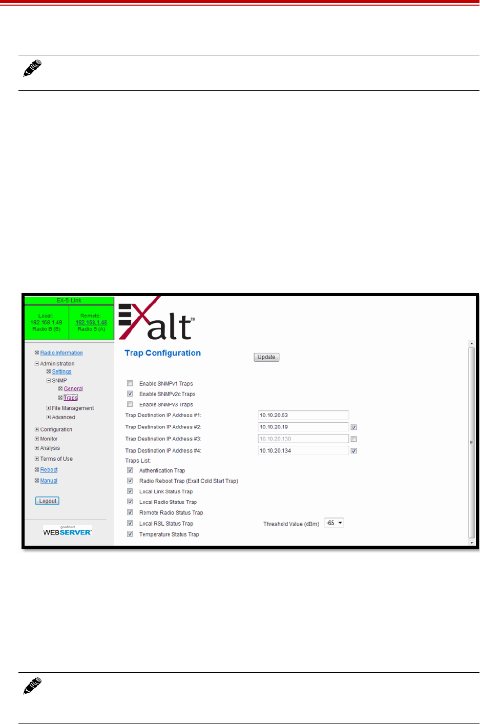
Exalt Installation and Management Guide
EX-i Series (TDD) Digital Microwave Radios
46 206501-019
2016-05-24
Enable the SNMPv3 options to allow entering read and read/write user names and passwords. These
entries are de-coupled from the standard radio user names and passwords. SNMPv3 provides full
management security.
SNMP Traps
SNMP traps alert the central network management system with important issues about the radio
system. Trap filters are set on the Traps Configuration page (Figure 29). Not all i-Series radios support
SNMP traps. Consult the release notes for more information.
Trap support for all versions of SNMP are provided and can be independently enabled. Enter the IP
address(es) to which the traps are directed in the Trap Destination IP Address field. The AUX port (or
the MAIN port when using in-band management) must be connected to the network to allow trap
information to reach the designated IP address. In a bridged network, this may not require special
network settings. In a routed network, the connected router must have a defined path for the IP address.
Figure 29 Trap Configuration page
Note: Users are encouraged to avoid enabling SNMPv1/V2c support due to known security
loopholes in these protocols.
Note: The Update button must be clicked to save any changes to this page.

Exalt Installation and Management Guide
EX-i Series (TDD) Digital Microwave Radios
206501-019 47
2016-05-24
The following traps are available:
•Authentication Trap: This is an SNMP standard trap when password information for SNMP is
incorrect. This can help identify unwanted intrusions into the management system and for
diagnosis of SNMP issues for valid users.
•Radio Reboot Trap: This trap is sent after any radio reboot to inform the manager of the reboot
status.
•Local/Remote Link Status Trap: This trap is sent when Link is in erroreds state (equivalent to the
Link LED on the radio front panel or the Link status bar in the upper-left of the Exalt GUI
window).
•Local/Remote Status Trap: This trap is sent when Status is in errored state (equivalent to the Status
LED on the front panel or the radio status box in the upper-left of the Exalt GUI window).
•Local RSL Status Trap: This trap is sent when the local RSL drops below the value set in the
Threshold Value (dBm) field. Buffers are provided so that continuous traps are not sent if the RSL
is bouncing near the set threshold value. This trap is reset only if the RSL rises to 3dBm above the
set threshold value and then drops below that value. Exalt recommends that this trap be set to a
value 5dBm or 10dBm above the threshold as a warning that the system has faded and may be
approaching an outage.
•Temperature Status Trap: This trap is sent when the internal temperature reaches the warning
point. This conveys that the external temperature control is in a fault state. Buffers are applied to
this trap to avoid multiple traps when the temperature remains near the warning point.
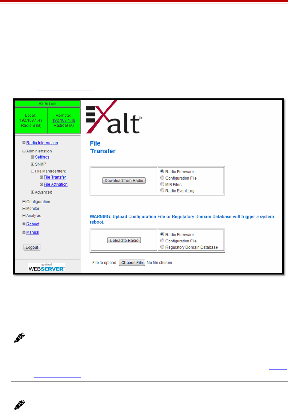
Exalt Installation and Management Guide
EX-i Series (TDD) Digital Microwave Radios
48 206501-019
2016-05-24
File Transfer Page
This page allows the administrator to upload and download files to and from the radio. Three types of
files can be uploaded: configuration, radio firmware, and Regulatory Domain Database (RDD). When
uploading Configuration Files, current configuration parameters are immediately overwritten, and the
unit automatically reboots. When uploading radio firmware files, the file is placed into reserve
memory space. After the new radio firmware file uploads, use the File Activation page to enable the
files (see File Activation Page).
Figure 30 File Transfer page
Up to four types of files can be downloaded: radio firmware, configuration, MIB, and event log. The
MIB file refers to the Management Information Base related to the Simple Network Management
Protocol (SNMP) function, and is only available on models which support SNMP. See Simple
Network Management Protocol (SNMP) Configuration for more information.
Note: Check the File Activation page before uploading radio firmware files. New file uploads
overwrite the secondary file location. If important files reside in the primary or secondary file
location, download them before uploading the new files. Only the active radio firmware file
can be downloaded. Therefore, to download the reserve file, it must first be activated (using
the Swap button). The current radio firmware and RDD versions can be viewed on the Radio
Information Page.
Note: Issues with the RDK may be caused when the Regulatory Domain Database (RDD) is
not up to date. Go to the Exalt Web site to download the current RDD.
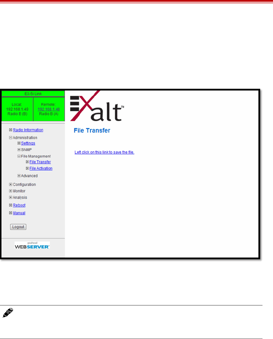
Exalt Installation and Management Guide
EX-i Series (TDD) Digital Microwave Radios
206501-019 49
2016-05-24
Use the following steps to download a file.
1Select the type of file to download (configuration or radio firmware).
2Click the Download button and wait for the radio to prepare the file for download.
3For the MIB file download, a second page/link appears.
4Left-click the link on the page to download the file to a desired location.
Figure 31 File Transfer page—download file link
File download and upload is useful when configuring several radios with similar settings. A copy of
the configuration file can also help restore radio settings. In addition, a copy of the Exalt default
configuration file is helpful to restore the radio to factory settings.
If copying the same configuration file into multiple radios, take as some parameters will match and
that may be undesirable. However, it may be easier to change just a subset of parameters rather than
every parameter. The following parameters can cause problems or confusion if they match at each of a
link:
•Radio Name
•Endpoint Identifier
•IP Address
Note: Do not change the name of any download file. The configuration file must be named
config.nv. To keep track of multiple configuration files, use a folder naming system or
temporarily rename the file, however, it must be named config.nv before it can be uploaded to
a radio. Never change radio firmware file names under any circumstances.

Exalt Installation and Management Guide
EX-i Series (TDD) Digital Microwave Radios
50 206501-019
2016-05-24
•IP Subnet Mask
•Default Gateway
The following parameters can match at both ends of the link:
•Link Name
•Link Security Key (although each link should be different)
•Admin and User passwords
•Bandwidth
•RF Frequency
•Link Distance
•Ethernet configurations
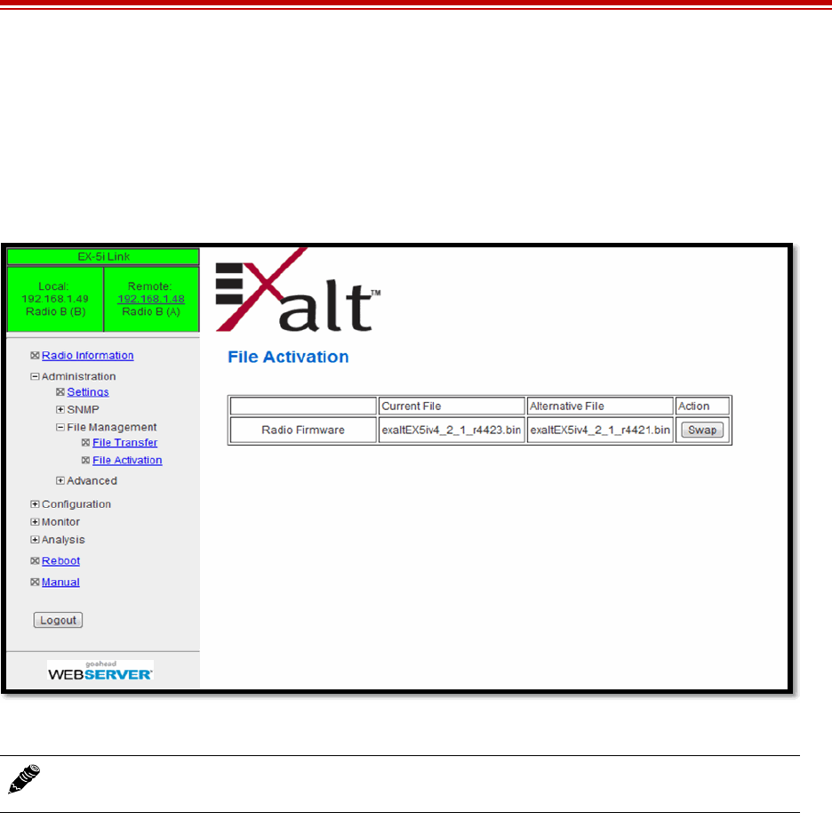
Exalt Installation and Management Guide
EX-i Series (TDD) Digital Microwave Radios
206501-019 51
2016-05-24
File Activation Page
Use this page to move stored or uploaded files for use on the radio. The page indicates which file is
currently in use, and which file is available for use. Click the Swap button to place the file in the
Alternative File column into the active state and move the file in the Current File column to the
Alternative File column.
Figure 32 File Activation page
Note: In all cases, the radio reboots after a new file is selected using the Swap function. This
places the radio out of service for a short time.
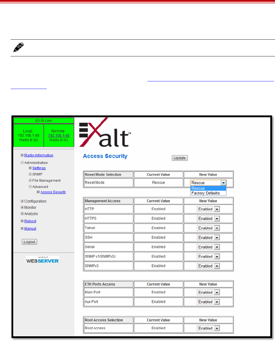
Exalt Installation and Management Guide
EX-i Series (TDD) Digital Microwave Radios
52 206501-019
2016-05-24
Access Security Page
This feature allows all radio management interfaces such as HTTP, HTTPS, SSH, Telnet, and serial to
be independently disabled/enabled. The default is all interfaces are enabled. Note that SNMP
interfaces are independently enabled/disabled on the Simple Network Management Protocol (SNMP)
Configuration page.
One management interface must be enabled at all times and the internal software ensures that one
interface is always available.
Figure 33 Access Security page
The ‘reset to critical factory defaults’ procedure is labeled ‘Rescue’ on this page, and restores only
those configurations required to access the radio (such as the IP address, mask, passwords, disables
VLANs, and so on).
This feature also ensures that all management interfaces are enabled after reset. Note that ‘Rescue’ is
the standard reset function and is recommended to retain all other configurations of the radio after a
reset. The reset feature can then be changed to reset all configurations to factory defaults. When this
feature is used, the entire radio configuration is changed back to the settings in the radio at
Note: As of this writing, this feature is not yet released on all models.

Exalt Installation and Management Guide
EX-i Series (TDD) Digital Microwave Radios
206501-019 53
2016-05-24
manufacture, except for installed License Keys and/or Regulatory Domain Keys, which are retained
even after a factory default reset.
For additional security, the Ethernet interfaces (MAIN and AUX) can be individually disabled. If both
interfaces are disabled, no Ethernet traffic can pass across the radio link and Ethernet cannot be used
for management. In this case, HTTP, HTTPS, Telnet, SSH, and all forms of SNMP are not available;
the only available management interface is Serial. This is only appropriate for radios exclusively
running TDM traffic (T1, E1, DS3), where serial access is sufficient. This feature is not available on
all models.
Root access is used by Exalt for remote software diagnosis (if the radio is accessible over the Internet
to Exalt and login credentials were provided). Root access is enabled by default.
If management security features on this page are used, then the management security features must be
manually reconfigured after any reset. Alternatively, after a reset you can upload a configuration file to
restore settings.
Note: If root access is disabled, there are conditions where Exalt may not be able to address
remotely that result in an RMA return that otherwise may not have been necessary had root
access been enabled. For this reason, it is advised to leave root access enabled, unless there
are significant concerns about access to the radio’s management ports where ‘hacking’ may
try to attack the Telnet or serial interfaces to gain access to the radio’s root directory. To allay
these types of issues, use private networks (such as VPN or VLAN) for management access.
Note: Models with this management security feature that also have DIP switches on the front
panel ignore DIP switch configuration after any reset.
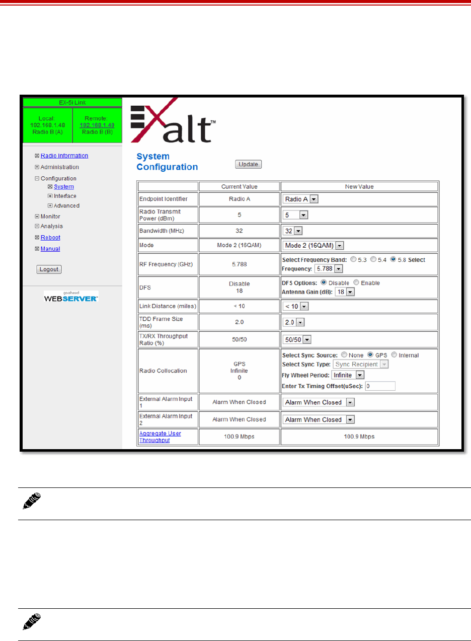
Exalt Installation and Management Guide
EX-i Series (TDD) Digital Microwave Radios
54 206501-019
2016-05-24
System Configuration Page
This page contains several critical system parameters.
Figure 34 System Configuration page
Most entries on this page are self-explanatory. The following lists unique or important parameters.
•Set the Radio Transmit Power (dBm) parameter to the designed level. The professional installer
sets this value or dictates the value of this setting to the system administrator following the system
design and local regulations. In many cases, this value must be set to a proper value to comply
with legal restrictions. Improper values can result in liability to the user and/or installer.
– Do not adjust the Radio Transmit Power parameter to a value higher than is legally allowed.
– Do not adjust the Radio Transmit Power parameter lower than the link budget and fade margin
can afford.
Note: For models requiring a Regulatory Domain Key (RDK), you must enter a valid RDK to
edit this page.
Note: Changing Radio Transmit Power may temporarily interrupt traffic. Small changes
in output power do not normally interrupt traffic, but larger changes may.

Exalt Installation and Management Guide
EX-i Series (TDD) Digital Microwave Radios
206501-019 55
2016-05-24
•Set the Bandwidth (MHz) parameter to the designed level. The value of this is determined in the
design/engineering stage. The Bandwidth parameter must also match at both ends of the link. In
conjunction with the Mode parameter, the Bandwidth parameter directly relates to the capacity,
latency, and the number of TDM circuits supported. The transmitter and receiver bandwidth are
modified using this parameter, making it critical that it be set with respect to the local RF noise and
interference profile, and/or in relation to any multi-link network design.
•Set the Mode parameter to the designed selection. The value of this setting is determined in the
design/engineering stage. The Mode parameter must match at both ends of the link. In conjunction
with the Bandwidth parameter, the Mode parameter setting directly relates to the capacity of the
system, as well as critical RF parameters, including receiver threshold, carrier-to-interference
ratio, and in some cases, maximum radio transmit power.
•Set the RF Frequency (GHz) parameter to the designed point. The value of this setting is
determined in the design/engineering stage. RF Frequency must match at both ends of the link. It
may be critical to set RF Frequency with respect to the local RF noise and interference profiles,
and/or in relation to any multi-link network design.
The frequency selection section includes the ability to select from either the complete list of
frequencies (“All”) that can be tuned for the selected band and bandwidth, or, in some cases, a pre-
selected list of non-overlapping center frequencies (“Preferred”) that Exalt determined provides
the most flexible collocation opportunities for large networks of Exalt radios
The frequency selection section includes a band selection button that must be enabled for the
frequency band of operation for which the link was engineered. Some bands may not be selectable
due to regulatory constraints. Some bands also require Dynamic Frequency Selection (DFS), based
Note: The link may be lost and unrecoverable through GUI control. If the link is lost due to
reduction of Radio Transmit Power, travel to the radio location(s) may be required to reset the
value.
Note: Changing Bandwidth will temporarily interrupt traffic. The Bandwidth parameter
must match at each end. Adjust the far-end radio first, and then the near-end radio. Changing
Bandwidth changes the radio’s threshold. A narrower bandwidth has better threshold
performance and improved interference immunity, therefore if changing to a wider
bandwidth, there is an opportunity that the link may be lost and unrecoverable through GUI
control. Check the available fade margin and interference profile to determine if the impact to
threshold and increased bandwidth is acceptable to maintain the link and the desired
performance. If the link is lost due to increasing the Bandwidth parameter, travel to the radio
location(s) may be required to reset the value.
Note: Changing Mode will temporarily interrupt traffic. The Mode setting must match at
each end. Adjust the far-end radio first, and then the near-end radio. Changing Mode changes
the radio’s threshold, carrier-to-interference ratio, and also may have impact on the Radio
Transmit Power. A lower mode has better threshold performance and carrier-to-interference
ratio, and in some cases, higher output power, therefore if changing to a higher mode (for
example, from Mode 1 to Mode 2), there is an opportunity that the link may be lost and
unrecoverable through GUI control. Check the available fade margin and interference profile,
and determine if the impact to RF performance is sufficient to maintain the link and desired
performance. If the link is lost due to increasing the Mode parameter, travel to the radio
location(s) may be required to reset the value.

Exalt Installation and Management Guide
EX-i Series (TDD) Digital Microwave Radios
56 206501-019
2016-05-24
on the active RDK. DFS is automatically enabled for these bands and is selectable for all other
bands.
•Set the Endpoint Identifier so that one end of the link is set to Radio A and the opposite end set to
Radio B. In single-link networks, it is unimportant which end is designated A or B. In multi-link
networks, however, it may be important to orient the links so that at any collocation site (where
there are multiple radios of the same type at the same site), all radios are set to the same Endpoint
Identifier (A or B). See Link Orientation and Synchronization.
•DFS is automatically enabled for any band where required based on the regulations that match the
active RDK. For bands where DFS is not required, it can still be selected. For DFS to operate
properly, set the antenna gain figure to match the installed transmission system gain (that is, the
gain of the antenna minus all losses between the radio and the antenna).
•Set the Link Distance (miles) parameter to the range that is equal to or greater than the actual link
distance. The value of this setting is determined in the design/engineering stage.
•Set the TDD Frame Size (ms) parameter to the designed level. The value of this setting is
determined in the design/engineering stage. The TDD Frame Size parameter must match at both
ends of the link. The TDD Frame Size parameter setting directly relates to the capacity, latency,
and number of TDM circuits that can be supported over the given link distance. In multi-link
networks, especially where there are collocated links, it is also important to set all radios to the
same TDD Frame Size setting to avoid self-interference. Future enhancement: The GPS or internal
sync function may be necessary for these networks. See RF Output Power Setting and Link
Orientation and Synchronization for more information.
Note: Changing RF Frequency will temporarily interrupt traffic. The RF Frequency
parameter setting must match at each end. Adjust the far-end radio first, and then the near-end
radio. If the RF Frequency parameter is changed to a frequency with interference, the link
may be lost and unrecoverable through GUI control. If the link is lost due to changing the RF
Frequency parameter, travel to the radio location(s) may be required to reset the value.
Note: Changing the Endpoint Identifier parameter requires a reboot of the radio to take effect.
The reboot temporarily interrupts traffic.
Note: When DFS is enabled, the radio temporarily stops transmitting for at least 60 seconds
to ensure that no radar interference is present. This is called “Channel Availability Check
(CAC).” The DFS status displays on the Alarms Page. Once CAC passes, the radio resumes
normal operation. If at any time during CAC or regular operation a qualifying radar signature
is detected, the radio shuts down communications for a minimum of 30 minutes. This is the
Non-Occupancy Period (NOP). Transmission only resumes after the NOP completes and then
only after a successful CAC.
Note: Changing the Link Distance parameter will temporarily interrupt traffic. The
Link Distance setting must match at each end and must not be less than the actual link
distance. Adjust the far-end radio first, and then the near-end radio. If the Link Distance
parameter is changed to a setting less than the actual distance, the link may be lost and
unrecoverable through GUI control. If the link is lost due to this situation, travel to the radio
location(s) may be required to reset the value. If the Link Distance parameter setting is set to
a distance unnecessarily higher than the actual link distance, the radio may have substantially
reduced performance with respect to throughput and latency.
Exalt Installation and Management Guide
EX-i Series (TDD) Digital Microwave Radios
206501-019 57
2016-05-24
•Set the TX/RX Throughput Ratio (%) parameter to program radio symmetry. The default setting is
50/50 for symmetrical, full-duplex throughput. Other throughput ratio options are 20/80, 80/20,
and 65/35, 35/65. See Link Symmetry.
For asymmetric throughput, only TDD frame size settings of 2ms and 5ms and RF Bandwidth
settings of 16MHz and higher are supported. The 64MHz/Mode2 configuration does not support
asymmetry due to capacity limitations of the 100BaseT interface.
•Radio Collocation enables the Sync feature. See Radio Synchronization.
•The External Alarm Inputs parameter can be ignored unless connecting external alarm sources to
the radio for monitoring the status of these external alarms through the radio management system
(see Interface Connections).
•Aggregate User Throughput parameter provides information about user capacity of the wireless
link, in the current configuration. The ‘new value’ column reflects throughput if changes are made
to Bandwidth, Mode, Link Distance, and/or TDD Frame Size. Click the “Aggregate User
Throughput” link for details on aggregate capacity.
Note: Changing the TDD Frame Size parameter will temporarily interrupt traffic. TDD
Frame Size parameters must match at each end. Adjust the far-end radio first, and then the
near-end radio. If the TDD Frame Size parameter is set to a value that cannot be supported for
the link distance, the link may be lost and unrecoverable through GUI control. If the link is
lost due to this situation, travel to the radio location(s) may be required to reset the value.
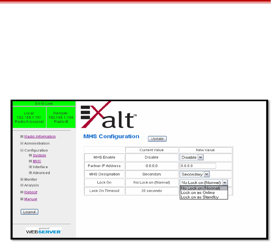
Exalt Installation and Management Guide
EX-i Series (TDD) Digital Microwave Radios
58 206501-019
2016-05-24
MHS Configuration Page
The -16 versions provide the Monitored Hot Standby (MHS) feature. The MHS kit is sold separately
and requires a valid license key, which is included with the kit. The radio system can be configured for
hardware redundancy at either end or both ends of the radio link. This configuration uses two radio
terminals per end with special hardware and cabling that switches the standby radio into the path when
the primary radio or its interfaces go offline. This minimizes any down-time for the link — especially
for hard-to-reach radio locations or critical traffic applications. Figure 35 shows the MHS
configuration screen.
Figure 35 MHS Configuration page
Refer to the MHS Implementation Guide for more information.
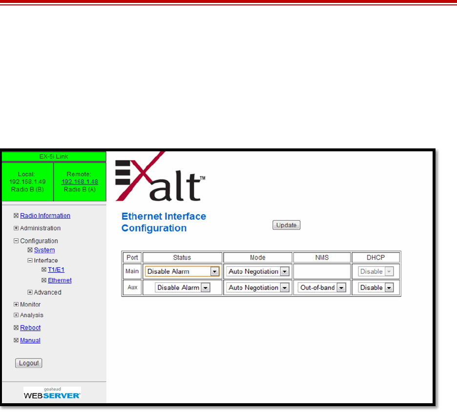
Exalt Installation and Management Guide
EX-i Series (TDD) Digital Microwave Radios
206501-019 59
2016-05-24
Ethernet Interface Configuration Page
This page allows the administrator to set the muting, alarm, and duplex settings of both the
ETHERNET MAIN and AUX connections.
It also allows determination of the management information for in-band (carried over the air and
available from both the MAIN and AUX connectors on either end of the link) or out-of-band (not
carried over the air and only available from the local AUX connector).
Figure 36 Ethernet Interface Configuration page
To ignore Ethernet alarms, disable the alarming of the MAIN and/or connector. Muting the MAIN
connection is desirable when connected equipment senses Ethernet signaling and makes decisions
(such as, spanning tree protocol enable) based on the Ethernet signal. If the MAIN connection has
muting enabled, the port is muted when the link is not active.
It may be desirable to disable the alarming of the AUX connector if it is not used.
Set the Ethernet interfaces on the radio and connected equipment to 100/full-duplex for best
performance. If the Ethernet ports are set to auto-negotiation, poor throughput performance may be a
result, as well as intermittent disconnections of the Ethernet connection.
Some models support the DHCP feature. When enabled, DHCP provides basic DHCP functions to
ease interfacing with a computer. By default DHCP is enabled for models that support it. If the
Ethernet port on the computer is set for DHCP addressing, on radio bootup (for up to 10 minutes) the
radio provides an IP address to the computer that is either 2 or 10 higher than the radio’s current IP
address (for example, if the radio’s IP address is 10.0.0.1, the computer will be set to 10.0.0.3 or
10.0.0.11, depending on the radio model and the software version running on the radio). The radio also
senses any DHCP server on the network and, if detected, mutes its own internal DHCP function.
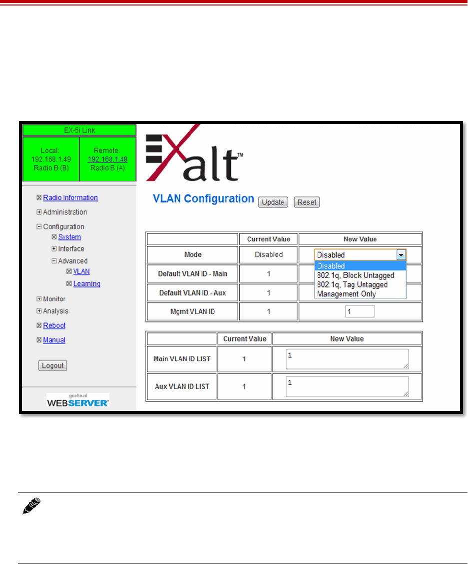
Exalt Installation and Management Guide
EX-i Series (TDD) Digital Microwave Radios
60 206501-019
2016-05-24
VLAN Configuration Page
VLAN is disabled as the default setting for Exalt radios. The Exalt radios still pass VLAN and non-
VLAN traffic across the link, but do not examine the VLAN traffic or act upon it. Enable VLAN using
the Exalt GUI for expanded VLAN support.
Figure 37 VLAN Configuration page
When VLAN is first enabled, all Ethernet interface ports (Aux and Main) are assigned as Default
VLAN, until the ports are configured with specific VLAN IDs. For example, a specific VLAN for
management access to the radio must be manually configured.
If any VLANs are configured in addition to the management VLAN, the radio automatically discards
traffic that not matching a configured VLAN. Non-tagged traffic, or traffic with tags matching VLANs
that are not configured, do not flow across the radio link.
Up to 16 unique VLANs can be configured. VLAN ID numbering ranges from 1 to 4094. The Native
(default) VLAN ID can be changed from the default setting. Every configured VLAN can also have a
logical name to help track the function of each VLAN.
VLAN configurations are maintained even when VLAN is disabled. That is, the VLANs can be
configured and the configuration saved, even though they are not active until VLAN is enabled. Use
Note: Once a management VLAN is configured or modified and the Update button clicked,
the management connection will likely be lost. The management connection to the radio must
follow the configuration to the assigned VLAN. After configuring and enabling the
management VLAN on the radio, reconfigure your network’s management access to match
the settings on the radio.

Exalt Installation and Management Guide
EX-i Series (TDD) Digital Microwave Radios
206501-019 61
2016-05-24
the following methods to restore the management connection if a mistake was made assigning the
management VLAN and access cannot be restored:
•Reset the radio to the critical factory defaults (see Reset to Critical Factory Settings).
•Connect to the Console port using a serial interface and the CLI, as described in Command Line
Interface (CLI), and reconfigure the VLAN settings.
Four VLAN configurations are provided:
•802.1q Block Untagged: To pass desired VLANs across the radio, they must be listed in the lower
tables per their respective interfaces. All other traffic, including untagged traffic, is not passed
across the link. The radio must be managed on a VLAN whose ID is set in the upper table. This
management VLAN ID is available to any interface IDs listed in this lower table.
•802.1q Pass Untagged: To pass desired VLANs across the radio, they must be listed in the lower
tables per their respective interfaces. All other VLAN traffic is not passed across the link, and
untagged traffic is passed across the link with no changes. The radio must be managed on a VLAN
whose ID is set in the upper table. This management VLAN ID is available to any interface IDs
listed in this lower table.
•802.1q Tag Untagged: To pass desired VLANs across the radio, they must be listed in the lower
tables per their respective interfaces. All other VLAN traffic is not passed across the link, and
untagged traffic is tagged with the programmed Default VLAN, per interface, as set in the upper
table. Any interface requiring the default VLAN ID to pass must have the Default VLAN ID listed
in the table below. The radio must be managed on a VLAN whose ID is set in the upper table. This
management VLAN ID is available to any interface IDs listed in the lower table.
•Management only: All traffic is passed transparently, except the radio is managed on an assigned
Management VLAN ID, as programmed in the upper table.
Note: Only one entry per VLAN ID is allowed. If the same VLAN ID is entered into the table
more than once, the radio uses the first assignment found in the table and ignores duplicate
entries.

Exalt Installation and Management Guide
EX-i Series (TDD) Digital Microwave Radios
62 206501-019
2016-05-24
T1/E1 Configuration Pages
These pages allow the administrator to selectively enable or disable the T1 or E1 circuits, one at a time.
For enabled T1/E1 circuits, additional configuration, including loopback functions, are available.
Disable the unused T1 or E1 so that the alarms are turned off and more throughput is allocated to the
Ethernet interface. Every enabled T1 or E1 input, even if there is no T1 or E1 signal present, reduces
the aggregate throughput of the Ethernet interface by roughly 3Mbps (for T1) or 4Mbps (for E1).
This page toggles between T1 and E1, as required, by clicking the Set to T1 or Set to E1 button. A
warning displays that a reboot is necessary, and the radio reboots if the administrator continues. This
will interrupt traffic. It may be necessary to re-login to the radio after the reboot completes. T1/E1
mode self-coordinates across the link if the link is active. This means that it only needs to be set while
connected at one end. In addition, enabling and disabling T1/E1 circuits also self-coordinates across
the link if the link is active. If a link is not active and T1/E1 enabling is a mismatch when a link is first
created, the Radio A configuration for T1/E1 enabling supersedes the settings on the Radio B
configuration, and changes the settings on Radio B.
T1 Interface Configuration Page
This page allows the administrator to enable/disable each individual T1 channel, set the Line Build Out
(LBO), Line Code (either AMI or B8ZS), and AIS enabling/disabling for each input. If enabled, the
radio places an AIS code on the output of the associated interface if and when the link fails or when
there is no T1 signal available from the far end to provide the user at the local end. Loopback controls
are also provided (see T1/E1 Loopback).
Note: Certain combinations of the TDD Frame Size, Link Distance, Mode, and Bandwidth
parameter settings limit the number of T1/E1 circuits that can be carried by the radio. In these
cases, certain fields on the T1/E1 Interface Configuration pages are not available, starting with
the highest port number. For example, for a 4x T1/E1 radio version, if only three (3) circuits can
be carried, port 4 is not available for configuration and is disabled. If only two circuits can be
carried, both ports 3 and 4 are not available. Increasing the TDD frame size and Mode
parameters, and/or increasing the Bandwidth parameter results in an increase in the supported
number of T1/E1 circuits.
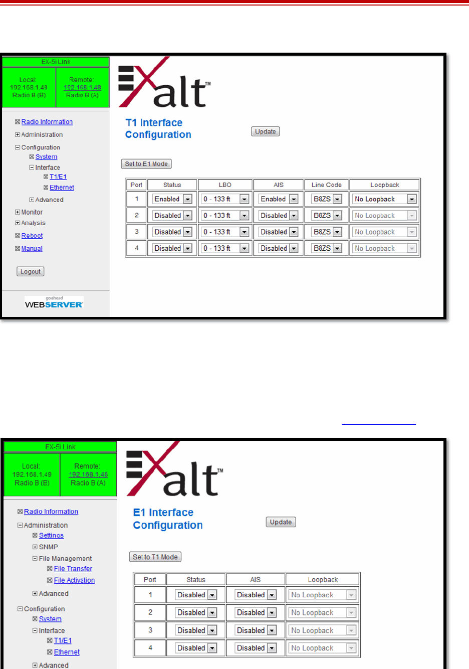
Exalt Installation and Management Guide
EX-i Series (TDD) Digital Microwave Radios
206501-019 63
2016-05-24
Figure 38 T1 Interface Configuration page
E1 Interface Configuration Page
This page allows the administrator to enable/disable each individual E1 channel. The AIS can also be
enabled and disabled for each input. If enabled, the radio places an AIS code on the output of the
associated interface if and when the link fails or when there is no E1 signal available from the far end
to provide the user at the local end. Loopback controls are also provided (see T1/E1 Loopback).
Figure 39 E1 Interface Configuration page
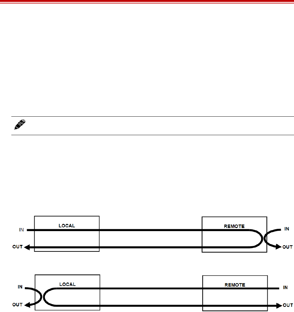
Exalt Installation and Management Guide
EX-i Series (TDD) Digital Microwave Radios
64 206501-019
2016-05-24
T1/E1 Loopback
Loopback is provided for any enabled T1 or E1 port. As shown in Figure 38 and Figure 39, the choices
are:
•No Loopback (default)
•External (local)
•External (remote)
•Internal
All loopback configurations control the loop at the Line Interface integrated circuit, which is the
device wired directly to the front panel ports.
External loopback modes are used in conjunction with an external test source. The designation of
‘local’ or ‘remote’ refers to where the loopback is occurring relative to the location where the loopback
is implemented. That is, on the radio being accessed, if External (remote) is selected, this loops the
signal back at the remote radio interface back towards the local radio. Likewise, if External (local) is
selected, the signal loops back at the local interface towards the remote radio (Figure 40 and Figure
41).
Figure 40 External (remote) loopback
Figure 41 External (local) loopback
When a local T1/E1 port is configured for External (remote) loopback, it is the same as configuring the
remote radio for External (local) loopback.
Note: Only one Internal loopback can be enabled at any time.
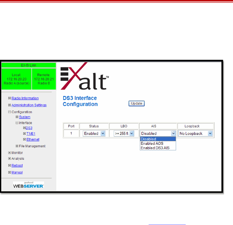
Exalt Installation and Management Guide
EX-i Series (TDD) Digital Microwave Radios
206501-019 65
2016-05-24
DS3 Configuration Page
This page allows the administrator to configure the DS3 interface (EX-5i-DS3 model only). The
interface should be disabled if there is no DS3 connected. The associated throughput is then allocated
to T1/E1 and/or Ethernet.
Figure 42 DS3 Configuration page
The Line Build Out (LBO) can be set for this interface. Also, the Automatic Insertion Signal (AIS) can
be disabled, or set to an All-Ones (AIS) or All-Zeros (AOS) signal type. In addition, some loopback
functions are provided, similar to the T1/E1 loopbacks described in T1/E1 Loopback.
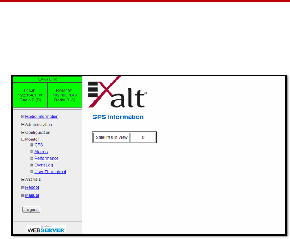
Exalt Installation and Management Guide
EX-i Series (TDD) Digital Microwave Radios
66 206501-019
2016-05-24
GPS Information Page
This page provides information on how many GPS satellites are within the view of the Exalt GPS
receiver. This page is active for implementations that include the GPS receiver connection for
synchronization. This information can be helpful for troubleshooting GPS issues.
Figure 43 GPS Information page
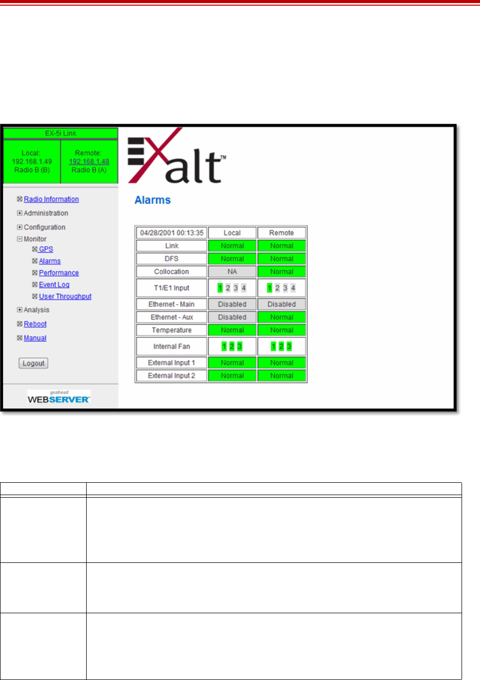
Exalt Installation and Management Guide
EX-i Series (TDD) Digital Microwave Radios
206501-019 67
2016-05-24
Alarms Page
This page provides an easy-to-read summary of the alarm status of both local and remote radios. The
colors on this page reflect the color of the alarms displayed on the radio front panel. However,
additional detail displays on this page to aid in quick assessment of issues and status.
Figure 44 Alarms page
Table 6 lists alarm status conditions that appear on this page.
Table 6 Alarm status indicators
Label Status
Link Indicates RF link status:
Green Solid = Error-free connection (BER<10e-6)
Yellow Solid = Errored connection (10e-3>BER >10e-6)
Red Solid = No link (BER>10e-3)
DFS Indicates the status of the Dynamic Frequency Selection (DFS).
Green = No DFS activity, normal transmission
Red = Either CAC or NOP is in progress.
Collocation Indicates the enabled/disabled status with Internal or GPS sync and current alarm status.
Green Solid = Sync enabled and sync input present
Yellow Solid = Sync enabled and missing proper sync input signal
Grey = Disabled

Exalt Installation and Management Guide
EX-i Series (TDD) Digital Microwave Radios
68 206501-019
2016-05-24
DS3 Indicates the status of the DS3 interface.
Green = Enabled and connection present
Yellow = Disabled and connection present
Red = Enabled and no connection present
Grey = Disabled or unavailable due to configuration
Ethernet – Main Green Solid = Data present
Grey = Disabled
Red Solid = No data present (and alarms are enabled)
Ethernet – Aux Green Solid = Alarm enabled and connection present
Yellow Solid = Alarm enabled and connection not present
Grey = Alarm disabled
Red Solid = No data present (and alarms are enabled)
T1/E1 Input Green = Enabled and connection present (clocking confirmed)
Red = Enabled and no connection present
Grey = Disabled or unavailable due to configuration
Temperature Green Solid = Normal temperature range
Yellow Solid = Exceeding normal temperature range
Internal Fan Indicates the internal fan status. There are 3 fans for redundancy
Green = Fan OK
Yellow = Fan in alarm
External Inputs
(1 and 2) Indicates the status of the external alarm inputs from the ALARMS connector, in accordance with
the open/closed logic defined on the System Configuration Page.
Green = Normal
Yellow = In alarm
DIP Switch Indicates the status of the front panel DIP switch for models without Access Security.
Yellow = Enabled
Grey = Disabled
Table 6 Alarm status indicators (Continued)
Label Status
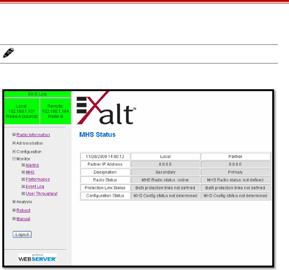
Exalt Installation and Management Guide
EX-i Series (TDD) Digital Microwave Radios
206501-019 69
2016-05-24
MHS Status Page
For -16 models with the MHS option, the MHS Status page shows the present alarm status of the MHS
functions. Figure 45 shows the MHS Status page.
Figure 45 MHS Status page
Refer to the MHS Implementation Guide for more information.
Note: MHS is a future enhancement.
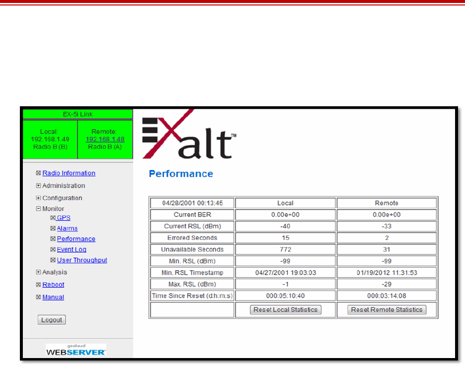
Exalt Installation and Management Guide
EX-i Series (TDD) Digital Microwave Radios
70 206501-019
2016-05-24
Performance Page
This page provides statistical information about the performance of the system in relation to the
integrity of the user data and the RF link.
Figure 46 Performance page
•The Current BER field indicates the current bit error rate of the link. If the link is operating
perfectly, this should indicate zero. Generally, the link should remain at a BER less than 1x10⁻⁶ (1
bit out of every million bits errored). This is the threshold performance specification and the
standard to which the link was engineered. However, radio links can and are affected by weather,
interference, and other external sources and will occasionally have a higher error rate. A link
remains operational unless the BER exceeds 1x10⁻³ (1 bit out of every hundred bits errored).
Consult the link design engineer for an understanding of the predicted error rate of the radio link as
it has been designed.
Many applications are unaffected by bit errors, but TDM circuits (for example, T1 or E1) are more
sensitive. Also, if the link operator is providing a service guarantee, this value may need to be
monitored or examined in cases of service issues. The behavior of BER in relation to other alarms
or measurements and external events can be very helpful in troubleshooting activities.
•Current RSL is the measurement of the received signal level at the radio antenna port. This is the
measured level of the RF signal coming from the opposite end of the radio link. The link was
engineered to a specific RSL by the link design engineer, and this RSL should be obtained during
installation and remain relatively stable during the operation of the link. RSL can and will vary as
a result of weather changes and other external sources, such as path obstructions. Once again, this
variation was part of the original design to achieve a certain level of performance over time. Bit
errors occur when the RSL falls to a level within roughly 3dB of the threshold specification. When
the RSL falls below the threshold specification, the link disconnects and will not reconnect until
the RSL is above the threshold specification. The behavior of RSL in relation to other alarms or
measurements and external events can be very helpful in troubleshooting activities.

Exalt Installation and Management Guide
EX-i Series (TDD) Digital Microwave Radios
206501-019 71
2016-05-24
•Errored Seconds (ES) indicates the total number of seconds that occurred where there was at least
one bit error since the last time that the radio statistics counter was reset. Generally, ES are not a
significant concern, so long as they are not continuous or above the anticipated performance based
on the original link engineering goals. If ES are continuous or at a high rate, this is normally an
indication of poor link performance due to poor RSL or interference, or severe impact by weather
or other environmental factors. However, similar to the performance factors previously listed, ES
can and will occur in any radio link. Once again, consult the link engineer to determine the original
design goals, and compare actual performance to these expectations to determine if any
improvements are necessary or if other problems may be causing excessive ES.
•Unavailable Seconds (also called UAS) are similar to ES, but this counter keeps track of every
second where the bit error rate equals or exceeds 1x10⁻³, as well as any seconds where there is a
complete loss of radio communication, over the period since the last counter reset. If Unavailable
Seconds are continuous or at a high rate, this is normally an indication of poor link performance
due to poor RSL or interference, or severe impact by weather or other environmental factors.
However, similar to the performance factors listed above, Unavailable Seconds can and do occur
in any radio link. Consult the link engineer to determine the original design goals, and compare
actual performance to these expectations to determine if any improvements are necessary or if
other problems may be causing excessive Unavailable Seconds.
•Minimum RSL indicates the worst (lowest) received signal level that occurred since the last
counter reset. It is helpful to know if the RSL dropped significantly from the normal level, or has
reached a level near or below threshold.
•Minimum RSL Timestamp indicates the date and time when the Minimum RSL occurred. This is
helpful for general troubleshooting, and especially comparing to items in the event log or
diagnostic charts from the same time period.
•Maximum RSL indicates the best (highest) RSL that occurred since the last counter reset. This
indicates the best performance of the radio link, which is normally equal to the installed value, and
is usually the designed value.
•Time Since Reset indicates the amount of time passed since the last counter reset. This helps to
quantify the seriousness of other statistics, such as ES and Unavailable Seconds, if there have been
high numbers of ES and/or Unavailable Seconds over a relatively short period of time.
All end-of-link statistics can be independently reset using the respective reset statistics button. It is
good practice to reset the statistics during link commissioning (after all antenna alignment is complete
and stable RSL at designed levels is achieved, and no more system reboots are anticipated). Regularly
review this page to record performance and reset the statistics so that the counters can more precisely
pinpoint issues.
Note: Unavailable Seconds do not register as ES. In other words, the ES counter counts all
seconds that are errored NOT INCLUDING the seconds that were classified as unavailable.
The total number of seconds with errors or outages is the sum of ES and Unavailable
Seconds.
Note: Resetting statistics from one end also resets the statistics for the same radio at the
opposite end. That is, if the Local statistics are reset, logging into the remote end shows the
Remote statistics on that end (which is the local radio in the first condition) as being reset at
the same time.
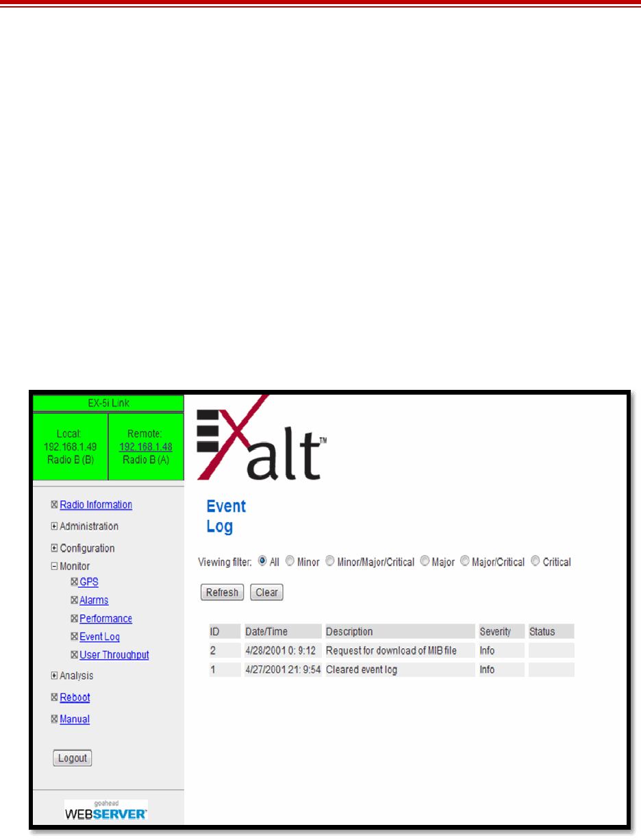
Exalt Installation and Management Guide
EX-i Series (TDD) Digital Microwave Radios
72 206501-019
2016-05-24
Event Log Page
Use this page to review a list of the events logged by the radio. The following items are listed in the
event log:
•Alarms
•Alarms clearing (normal)
•Radio reboots
•Radio configuration changes
•System logins
Every event is tagged with the time that the event occurred, and a severity and type. The event log also
allows filtering to limit the view of the log to only the level(s) of desired information.
The log contains the last 1000 events. Events are deleted on a FIFO basis, erasing the oldest entries to
make room for the newest entries. The event log can be cleared and downloaded from the file transfer
page (some models may require a software upgrade to enable this feature).
Figure 47 Event Log page
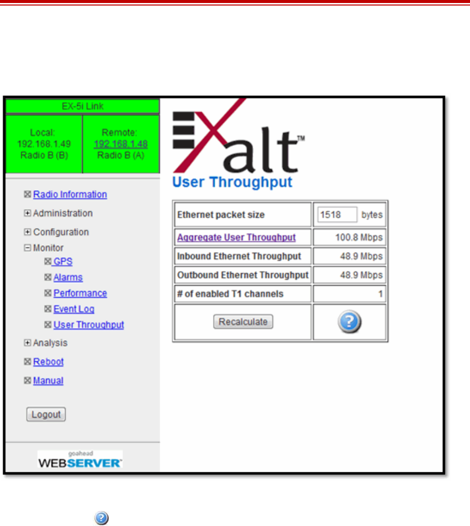
Exalt Installation and Management Guide
EX-i Series (TDD) Digital Microwave Radios
206501-019 73
2016-05-24
User Throughput Page
This page illustrates the user throughput of the radio, as configured.
Figure 48 User Throughput page
Click the help icon ( ) to go to page on how this information is determined (Figure 49).

Exalt Installation and Management Guide
EX-i Series (TDD) Digital Microwave Radios
74 206501-019
2016-05-24
Figure 49 Aggregate User Throughput Help page
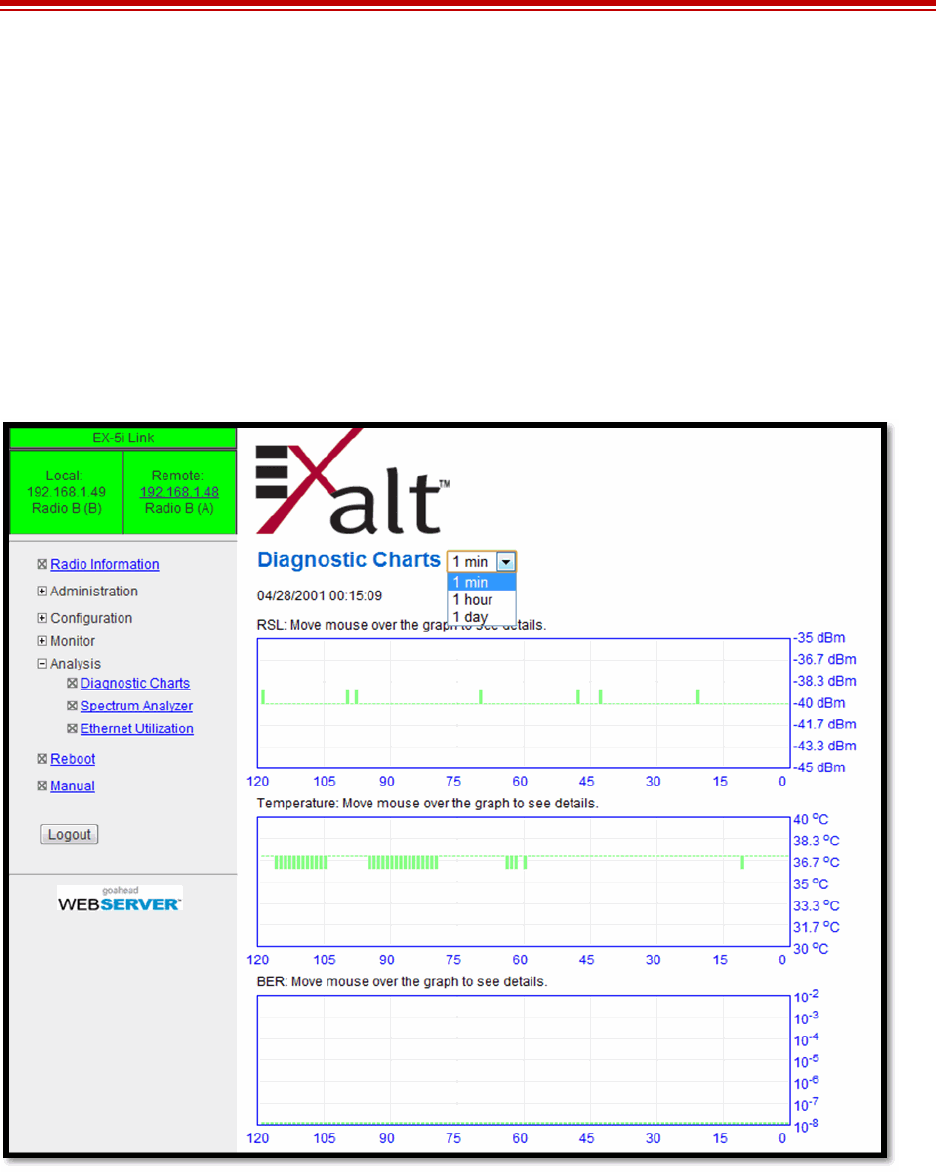
Exalt Installation and Management Guide
EX-i Series (TDD) Digital Microwave Radios
206501-019 75
2016-05-24
Diagnostic Charts Page
Use this page as an aid in troubleshooting. This page illustrates the historical (and current)
performance for three parameters: RSL, Radio Temperature, and BER.
The horizontal scale illustrates 120 points of time measurement and is synchronized on all three
graphs. The scale displays in minutes, hours, or days from the last two hours (120 minutes), five days
(120 hours), or four months (120 days). All information is stored, so all of these periods are available
for short- and long-term performance analysis. The right side of a graph represents the most recent
measurement, and data ‘marches’ from the right-to-left at every interval.
The vertical scale of each chart independently scales to show the maximum resolution based on the
maximum variation of the data over the selected time measurement.
Figure 50 Diagnostic Charts page
Use the cursor to point to any spot on any of the three charts, and all three charts illustrate the
measurements taken for that time interval in the upper-left corner of each chart. The time interval is
indicated by T=(value). This is followed by the value of the measurement, listing the highest value,
lowest value and average value measured over that time interval.
For example, if the displayed time interval is minutes, and the cursor is held at the T=17 mark on the
horizontal axis, the measurements shown indicate performance from 17 minutes ago. The high/low/
average values shown on each chart are measurements made across that specific one-minute interval.

Exalt Installation and Management Guide
EX-i Series (TDD) Digital Microwave Radios
76 206501-019
2016-05-24
Changes in RSL often have an impact on BER, and this can be confirmed by looking for synchronized
events. When BER events occur without corresponding changes in RSL, this normally indicates
interference, atmospheric changes, transmission system issues (such as problems with cables,
connectors, or antennas), or possibly radio hardware problems.
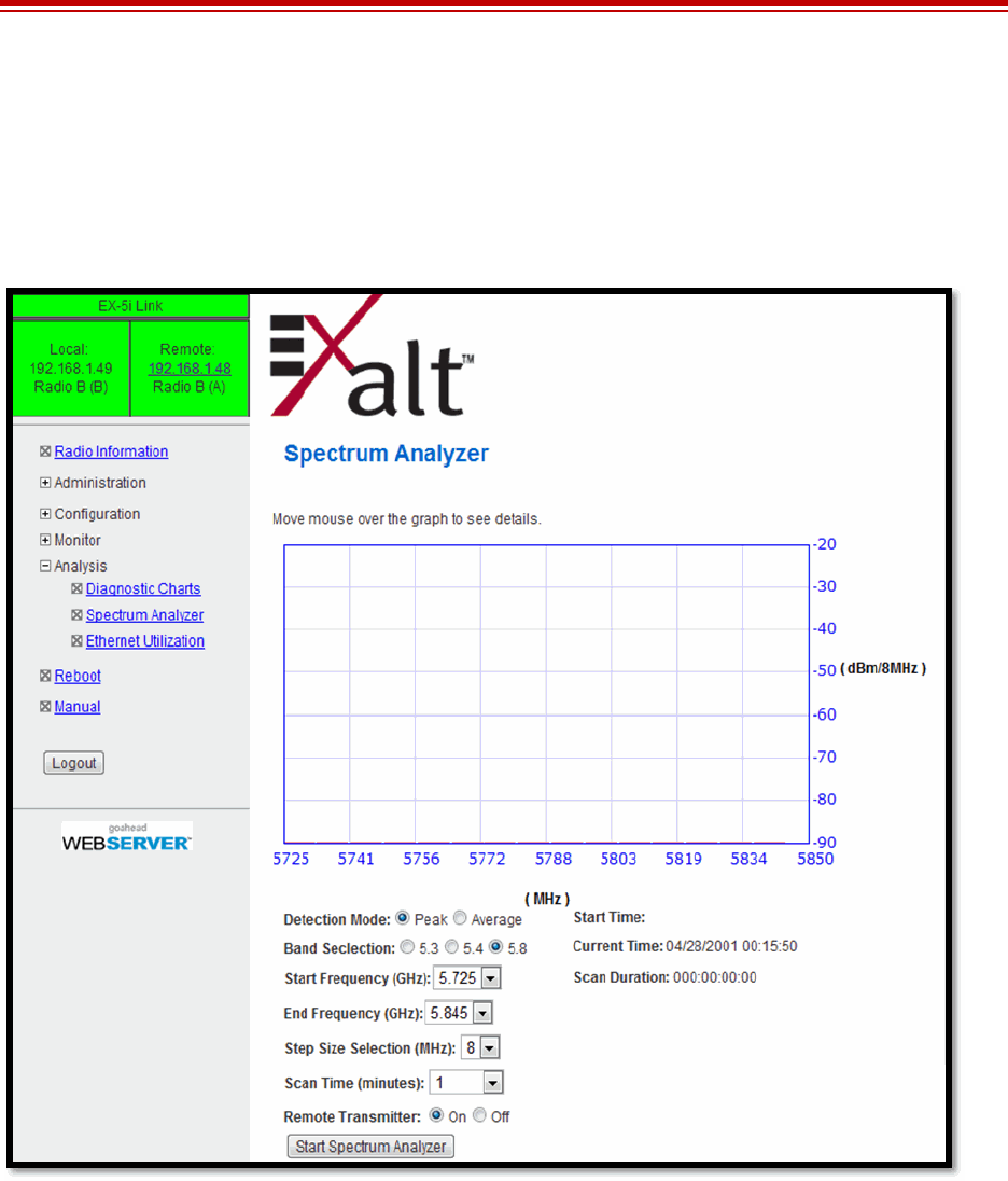
Exalt Installation and Management Guide
EX-i Series (TDD) Digital Microwave Radios
206501-019 77
2016-05-24
Spectrum Analyzer Page
The spectrum analyzer feature provides a useful pre-planning and troubleshooting tool. This feature is
only available on radios with firmware supporting the spectrum analyzer. Perform a spectrum analysis
after deployment and just before commissioning to maintain a record of the spectrum at the time of
deployment. Figure 51 shows the Spectrum Analyzer page.
Figure 51 Spectrum Analyzer page
While a professional spectrum analyzer provides higher levels of control and precision for pre-
planning, the Spectrum Analyzer page allows evaluation of the RF spectrum as seen at the radio’s RF
input port prior to deployment. This is useful for pre-planning the center frequency and occupied
bandwidth, and to determine polarization and antenna type and mounting locations.
For troubleshooting, enable the spectrum analyzer to scan the desired segment or full band of the
frequency range. Select the step size and set the remote radio transmitter ON or OFF. This allows
viewing of the clean spectrum without the remote transmitter on and a comparison of the remote
transmitter in the midst of other signals.
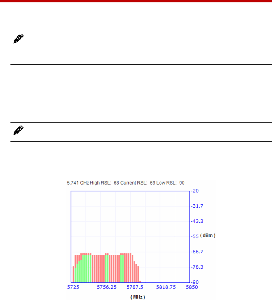
Exalt Installation and Management Guide
EX-i Series (TDD) Digital Microwave Radios
78 206501-019
2016-05-24
Use the smallest step size to obtain the finest view of the spectrum. The spectrum analyzer can be set
to match the start and stop frequency for a dwell mode. Peak and average detection modes are also
available. Peak detection is helpful for capturing intermittent events such as pulsed emissions.
It is best to set the Scan Time option to a time value as opposed to using the ‘infinity’ setting. If your
management computer is connected to the radio through the radio link, access to the GUI is interrupted
during the duration of the analysis.
The spectrum analyzer graph displays received signals in red, gray, or green (Figure 52), normalized in
dBm to the resolution bandwidth of the analyzer. Red indicates the highest level detected during the
entire scan. Gray indicates the lowest value seen during the scan. Green indicates the last value
measured at that frequency.
Figure 52 Spectrum analyzer graph example
A completely green vertical box indicates that the signal maintained a steady level for the entire scan
or that the last scan measured at a strong or stronger level than the rest of the analysis. A completely
red vertical box indicates that there was a signal at some point during the scan, but that the signal was
not detected at the last scan. A graph displaying green on the lower part and red at the upper part
indicates that at some time during the scan, a signal was detected at a higher level than was detected
during the last scan. A gray bar usually has a small green and/or red dot at the top or a green and/or red
bar extending above it. The top of a gray bar indicates the lowest value seen during the scan.
The last spectrum analyzer scan performed displays in this page until the radio is rebooted. You can do
a screen capture for record keeping and for comparison to future analyses. The time and date of the
analysis displays on the page, which is handy as a reference in a screen capture.
Note: Enabling the spectrum analyzer interrupts all radio traffic for the duration of the
analysis. In addition, access to the radio’s GUI may also be interrupted, depending on the
location of the interfaced computer relative to the radio where the spectrum analysis is
occurring. The GUI is available at the completion of the spectrum analysis.
Note: The result of selecting infinity may be complete loss of contact to that radio and may
require a physical visit to the radio location to disable the spectrum analyzer.
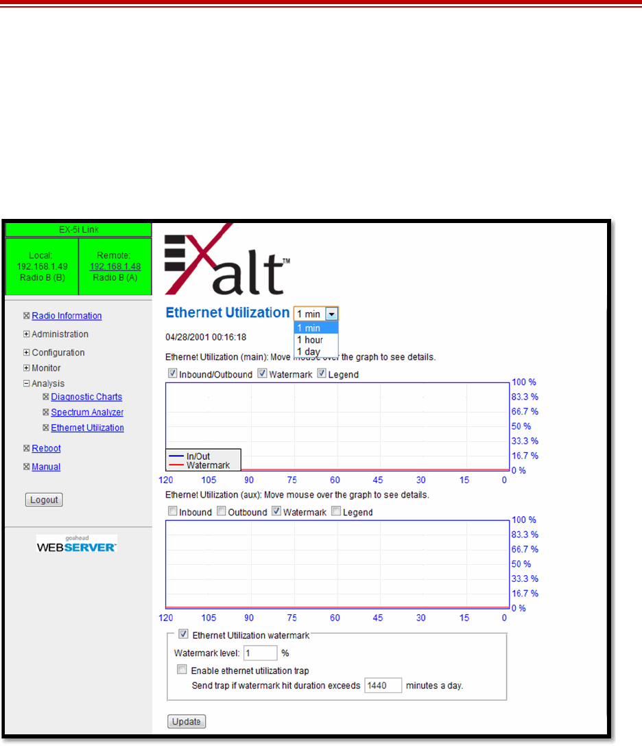
Exalt Installation and Management Guide
EX-i Series (TDD) Digital Microwave Radios
206501-019 79
2016-05-24
Ethernet Utilization Page
This page shows a chart for each Ethernet interface to illustrate inbound and outbound packet
utilization. This is shown as a percentage of the interface configuration (that is, if your interface is set
for 100BaseT, then 100% represents 100Mbps. Compare offered load (inbound) to delivered load
(outbound) to determine if radio capacity is a bottleneck for the data transfer. This chart can illustrate
inbound and/or outbound utilization, and uses different colors for data entry. The legend can be
hidden.
Figure 53 Ethernet Utilization page
Note that outbound utilization never exceeds the rate where a radio is configured. For example, if the
radio is configured for a 55 Mbps capacity, outbound utilization will never exceed 55 Mbps at
100BaseT.
The Ethernet Utilization Watermark level function allows administrators to receive an SNMP trap
when watermark conditions are exceeded. For example, if a radio is configured for 55 Mbps capacity,
the administrator may wish to be warned if the radio exceeds 50 Mbps for more than 1 hour per day. In
this case, set the Watermark level to 50% and the trap duration to 60 minutes. Traps must be enabled to
activate this function.
When the watermark level function is enabled, a line on the chart appears for data comparison to the
watermark.
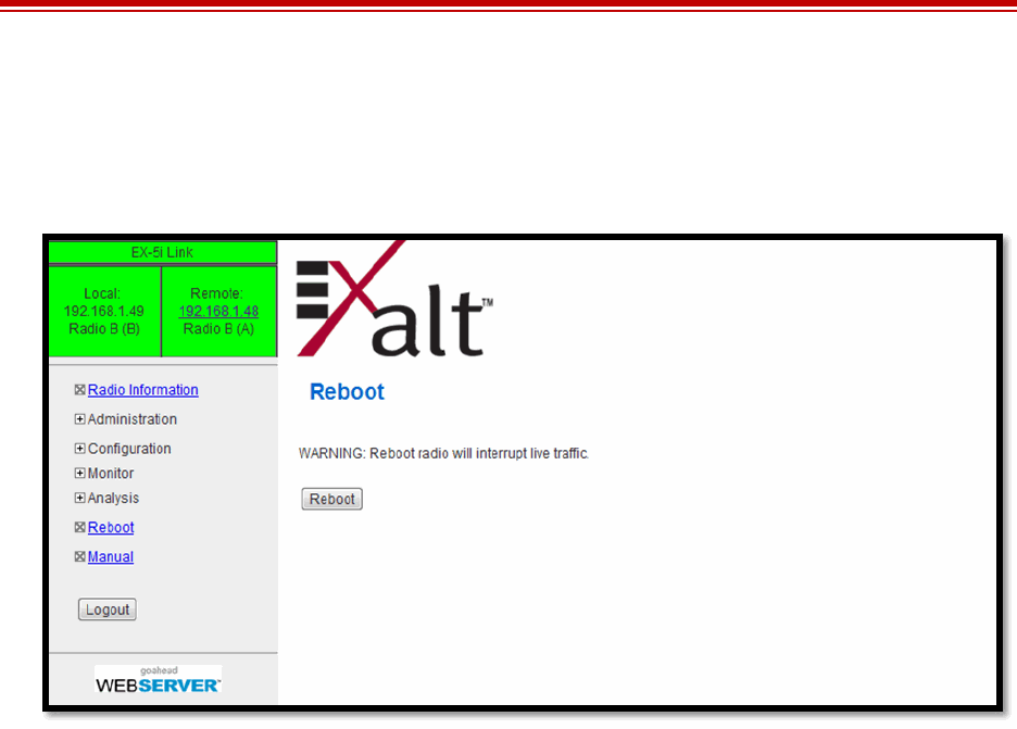
Exalt Installation and Management Guide
EX-i Series (TDD) Digital Microwave Radios
80 206501-019
2016-05-24
Reboot Page
Use this page to reboot the radio. The function may never be required, but can be used in emergencies.
All configurations that require a reboot automatically reboot on administrator confirmation.
Figure 54 Reboot page
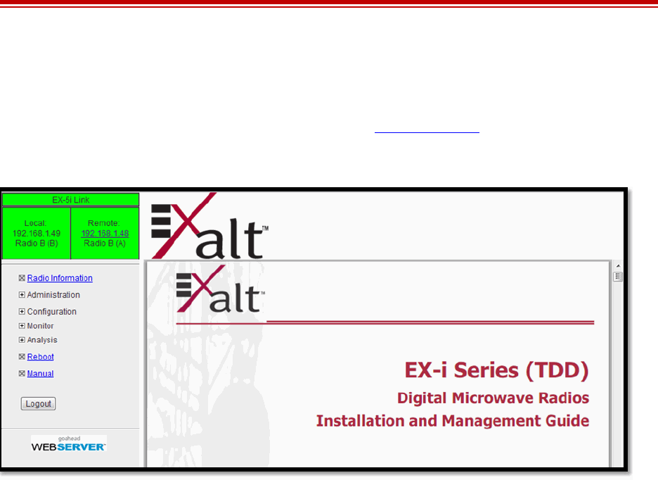
Exalt Installation and Management Guide
EX-i Series (TDD) Digital Microwave Radios
206501-019 81
2016-05-24
Manual Page
The manual (this document or the version that matches the installed firmware) is available within the
GUI. Adobe Acrobat Reader 5.5 or higher is required (go to www.adobe.com to download Acrobat
Reader). Click the Manual link to display the manual within the browser window. Once the manual
displays, click the save button on the PDF toolbar to download the manual locally.
Figure 55 Manual page

Exalt Installation and Management Guide
EX-i Series (TDD) Digital Microwave Radios
82 206501-019
2016-05-24
Specifications
This section presents specifications for the i-Series of Digital Microwave Radios.
Physical Specifications
Common System Specifications
Physical Configuration Single-piece Indoor Unit (IDU)
Dimensions (HxWxD), (std models) 1RU: 1.75" x 17" x 14"/ 4.5 x 43.2 x 35.6 cm
Dimensions (HxWxD), (-16 models) 1.5RU: 2.63" x 17" x 14"/ 6.7 x 43.2 x 35.6 cm
Weight (std models) 11.3 lbs/5.1 kg
Weight (-16 models) 12 lbs/5.5kg
Operating Temperature -13° +149°F /-25° to +65°C
Altitude 15,000'/4.6 km
Humidity 95% non-condensing
Safety EN 60950-1, IEC 60950-1
EMC EN 301 489-17 (EX-5i and EX-2.4i series), FCC Part 15,
IC Part 15
Tuning Resolution 1MHz; 5MHz for EX-4.9i and some regulatory domains
Power Control Step Size 0.5dB
Selectable Modulation Modes Mode 1 (QPSK); Mode 2 (16QAM)
Selectable Channel Bandwidths 8MHz, 16MHz, 32MHz, 64MHza
EX-4.9i and some regulatory domains:
10MHz, 20MHz, 40MHz
a. Not all bandwidth and mode combinations are available on all radio models. Some radios may require
specific software license keys, which can be purchased from your authorized Exalt representative.
Selectable Frame Lengths (ms) 0.5, 1, 2, 2.5, 4, 5
Maximum Aggregate User Capacity
Error Floor 10-12
Frequency Stability +7 ppm
Link Security 96-bit Security Code, optional NIST FIPS-197 compliant
128-bit or 256-bit AES encryption.
Mbps Mode 1 Mode 2
8 / 10 13 27
16 / 20MHz 27 55
32/40MHz 55 110
64MHz1110 216

Exalt Installation and Management Guide
EX-i Series (TDD) Digital Microwave Radios
206501-019 83
2016-05-24
EX-2.4i System Specifications
Frequency Band 2400 to 2483.5MHz
Tunable Range 2406 to 2468MHz
Output Power (at full power) +27dBm (0.5W), Mode 1
+24dBm (0.25W), Mode 2
Output Power (at minimum power) +7dBm
Selectable Channel Bandwidths 8MHz, 16MHz, 32MHz, 64MHza
a. 64MHz BW is enabled for the EX-2.4i though a firmware option. 64MHz BW is enabled for the EX-2.4i-16
when the 16xT1/E1 license key is enabled.
Receiver Threshold (BER=10-6)
Maximum RSL Mode 1: -25dBm error-free; 0dBm no damage
Non-overlapping channels 8MHz: 8; 16MHz: 4; 32MHz: 2; 641: 1
Regulatory Compliance FCC 15.247; IC RSS-210
FCC ID TTM-102P40I
IC ID 6254A-102P40I
Emission Designator(s)
dBm Mode 1 Mode 2
8MHz -88 -80
16MHz -85 -77
32MHz -82 -74
64MHz1-79 -71
Mode 1 Mode 2
8MHz 10M2W7D 9M9W7D
16MHz 17M3W7D 19M0W7D
32MHz 34M7W7D 36M0W7D
64MHz* 60M7W7D 61M3W7D

Exalt Installation and Management Guide
EX-i Series (TDD) Digital Microwave Radios
84 206501-019
2016-05-24
EX-4.9i System Specifications
Frequency Band 4940 to 4990 MHz
Tunable Range 4945 to 4985 MHz
Output Power (at full power, Mode 1) +24dBm (20MHz BW)
+22dBm (10MHz BW)
Output Power (at minimum power) +4dBm
Selectable Channel Bandwidths 10MHz, 20MHza
a. Mode 2 for 20MHz BW is enabled through firmware options for the EX-4.9i.
Receiver Threshold (BER=10-6)
Maximum RSL Mode 1: -25dBm error-free; 0dBm no damage
Non-overlapping channels 10MHz: 5; 20MHz: 2
Regulatory Compliance FCC Part 90; IC RSS-111
FCC ID TTM-104P90I
IC ID 6254A-104P90I
Emission Designator(s)
dBm Mode 1 Mode 2
10MHz -86 -78
20MHz -83 -751
10MHz 8M72W7D
20MHz 19M0W7D

Exalt Installation and Management Guide
EX-i Series (TDD) Digital Microwave Radios
206501-019 85
2016-05-24
EX-5i System Specifications, 5.3GHz Band
Frequency Band 5250 to 5350 MHz
Tunable Range 5260 to 5332 MHz
Output Power (at full power) +13dBm (0.02W)
Output Power (at minimum power) -7dBm
Receiver Threshold (BER=10-6)
Maximum RSL Mode 1: -25dBm error-free; 0dBm no damage
Non-overlapping channels 8MHz: 10; 16MHz: 5; 32MHz: 2; 64MHza: 1
a. 64MHz BW is enabled through a firmware option for the EX-5i. 64MHz BW is enabled when the 16xT1/E1
license key is enabled for the EX-5i-16.
Regulatory Compliance FCC 15.407; IC RSS-210
FCC ID TTM-105P25M
IC ID 6254A-105P25I
Emission Designator(s)
dBm Mode 1 Mode 2
8/10MHz -86 -78
16/20MHz -83 -75
32/40MHz -80 -72
64MHz1-77 -69
8MHz 7M8W7D
16MHz 15M7W7D
32MHz 30M9W7D
64MHz160M8W7D

Exalt Installation and Management Guide
EX-i Series (TDD) Digital Microwave Radios
86 206501-019
2016-05-24
EX-5i System Specifications, 5.4GHz Band
Frequency Band 5470 to 5725 MHz
Tunable Range 5488 to 5715 MHz
Output Power (at full power) +13dBm (0.02W)
Output Power (at minimum power) -7dBm
Receiver Threshold (BER=10-6)
Maximum RSL Mode 1: -25dBm error-free; 0dBm no damage
Non-overlapping channels 8MHz: 29; 16MHz: 14; 32MHz: 7; 64MHza: 3
a. 64MHz BW is enabled through a firmware option for the EX-5i. 64MHz BW is enabled when the 16xT1/E1
license key is enabled for the EX-5i-16.
Regulatory Compliance FCC 15.407; IC RSS-210
FCC ID: TTM-105P25M
IC ID: 6254A-105P25I
Emission Designator(s)
dBm Mode 1 Mode 2
8/10MHz -86 -78
16/20MHz -83 -75
32/40MHz -80 -72
64MHz1-77 -69
8MHz 8M27W7D
16MHz 16M7W7D
32MHz 33M0W7D
64MHz165M0W7D

Exalt Installation and Management Guide
EX-i Series (TDD) Digital Microwave Radios
206501-019 87
2016-05-24
EX-5i System Specifications, 5.8GHz Band
Frequency Band 5725 to 5850 MHz
Tunable Range 5731 to 5844 MHz
Output Power (at full power) +24dBm (0.25W), Mode 1
+21dBm (0.13W), Mode 2
Output Power (at minimum power) +4dBm
Receiver Threshold (BER=10-6)
Maximum RSL Mode 1: -25dBm error-free; 0dBm no damage
Non-overlapping channels 8MHz: 15; 16MHz: 7; 32MHz: 3; 64MHza: 1
a. 64MHz BW is enabled through a firmware option for the EX-5i. 64MHz BW is enabled when the 16xT1/E1
license key is enabled for the EX-5i-16.
Regulatory Compliance FCC 15.407 (b) (4) (ii); IC RSS-210
FCC ID TTM-105P25M
IC ID 6254A-105P25I
Emission Designator(s)
(dBm) Mode 1 Mode 2
8/10MHz -86 -78
16/20MHz -83 -75
32MHz -80 -72
64MHz1-77 -69
8MHz 8M4W7D
16MHz 16M7W7D
32MHz 33M1W7D
64MHz164M5W7D

Exalt Installation and Management Guide
EX-i Series (TDD) Digital Microwave Radios
88 206501-019
2016-05-24
Interfaces
RF
T1/E1 (x4 or x16)
DS3
Ethernet (x2)
Console (Serial)
Alarm
Connector N-type female
Impedance 50 Ohms
Connector RJ-45 (RJ48C), female
T1 Impedance 100 Ohms, balanced
T1 Line Codes AMI, B8ZS, selectable
T1 LBO Settings (in ft.) 0-133, 133-266, 266-399, 399-533, 533-655
T1 Clocking Speed 1.544 Mbps
T1 Compliance ANSI T1.102-1987; ITU-T; G.823; GR-49T-CORE
E1 Impedance 120 Ohms, balanced
E1 Line Codes HDB3
E1 Clocking Speed 2.048 Mbps
E1 Compliance CEPT-1; G.703; ITU-T-G703
Connector BNC, female (x2, In/Out)
DS3 Impedance 75 Ohms, unbalanced
DS3 Line Code B3ZS
DS3 LBO Settings (in ft.) 0-133, 1330266, 266-399, 399-533, 533-655
DS3 Clocking Speed 44.736 Mbps
DS3 Compliance ANSI T1.102-1993; GR-499-CORE
Connectors RJ-45, female, auto-MDIX
Interface Speed 10 or 100 Mbps
Duplex Half, full, auto, selectable
Compliance 802.3
Connector 9-pin sub-D, female
Interface Speed 9600 bps
Compliance EIA-574 DTE (RS-232)
Connector 9-pin sub-D, female
Inputs (2) TTL/Closure
Outputs (2) Relay (Form C)

Exalt Installation and Management Guide
EX-i Series (TDD) Digital Microwave Radios
206501-019 89
2016-05-24
Sync (In and Out)
Power
Connector RJ45, female
Signal 1 pps (GPS)
Connector 6-pin barrier strip
Input Voltage (EX-2.4i) 40–60VDC (most EX-2.4i radios conform to the same
power as EX-5i below, the front panel of the radio
indicates the proper input per the manufacturing date of
the radio)
Consumption (EX-2.4i) <34W (0.7A @ 48V)
Input Voltage (EX-5i and EX-4.9i) 20–60VDC
Consumption (EX-5i and EX-4.9i) <38.5W (0.8A @ 48V; 1.6A @ 24V)
Input Voltage (-16 models and DS3 models) 20–60VDC
Consumption (-16 models and DS3 models) < 45W (0.9A @ 48V; 1.8A @ 24V)
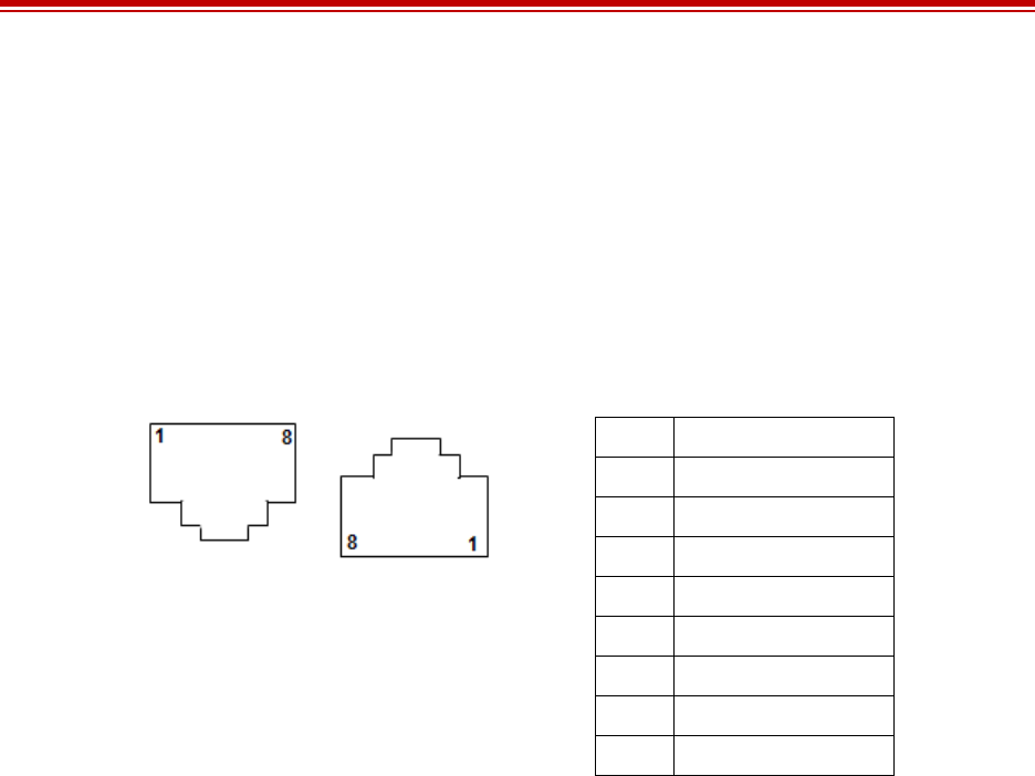
Exalt Installation and Management Guide
EX-i Series (TDD) Digital Microwave Radios
90 206501-019
2016-05-24
Interface Connections
This section provides the pin number assignment and wiring information for the connectors on the
i-Series radios. All connectors are shown as viewed from the radio front panel.
T1/E1 Connections
There are two orientations of T1/E1 connections. Channels 1 and 2 have the securing tab towards the
top of the connector while Channels 3 and 4 have the securing tab towards the bottom of the connector.
Figure 56 illustrates the pin orientation and functionality of these connectors.
Figure 56 T1/E1 connectors
Pin Function
1 Tip Out (from radio)
2 Ring Out (from radio)
3 Ground
4 Tip In (to radio)
5 Ring In (to radio)
6 Ground
7 Unused
8 Unused
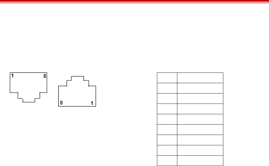
Exalt Installation and Management Guide
EX-i Series (TDD) Digital Microwave Radios
206501-019 91
2016-05-24
Ethernet Connections
There are two orientations of Ethernet connections. AUX has the securing tab towards the top of the
connector while MAIN has the securing tab towards the bottom of the connector. Figure 57 illustrates
the pin orientation and functionality of these connectors.
Figure 57 Ethernet connectors (MAIN and AUX)
The Ethernet connections implement Auto-MDIX, and therefore either ‘straight’ or ‘crossover’
Ethernet cables can be used, independent of the wiring of the connected device.
Depending on the settings of in-band or out-of-band NMS, both the MAIN and AUX ports can access
the far-end radio (if in-band) or not (out-of-band). In the case of out-of-band setting, only the AUX
port can access the GUI, while only the MAIN port carries Ethernet traffic across the link.
Pin Function
1 Paired with Pin 2
2 Paired with Pin 1
3 Paired with Pin 6
4 Unused
5 Unused
6 Paired with Pin 3
7 Unused
8 Unused

Exalt Installation and Management Guide
EX-i Series (TDD) Digital Microwave Radios
92 206501-019
2016-05-24
Sync Connections
There are two sync connectors: Sync In and Sync Out. The Sync In connector is normally connected to
a (custom) GPS antenna system, or to the Sync Out connector of a collocated radio.
Figure 58 Sync In connector
Figure 59 Sync Out connector
For internal sync, connect pins 2 and 6 and cross over pins 3 and 5.
For GPS connections, the interconnection cable between radios must cross over pins 3 and 5, with all
other pins wired straight through.
All configurations do not require connections on pins 4, 7, and 8.
Pin Function
1 +5V Power Out (to GPS antenna)
2Ground
3 Tx Data (to GPS antenna)
4 Enable (to GPS antenna)
5 Rx Data (from GPS antenna)
6 1 pps Timing Signal (from GPS antenna)
7 Unused
8 Unused
Pin Function
1 +5V Power In (from connected radio)
2 Ground
3 Tx Data (to connected radio)
4 Unused
5 Rx Data (from connected radio)
6 1 pps Timing Signal (to connected radio)
7 Unused
8 Unused
Exalt Installation and Management Guide
EX-i Series (TDD) Digital Microwave Radios
206501-019 93
2016-05-24
Alarm Connector
The Alarm connector provides two alarm outputs that can be connected to external alarm collection
equipment. The connector also allows connection of up to two external alarm sources, where the radio
will report the status of these connections through the radio network management. Output alarm
connections are ‘Form C’ style connections, performing alarm logic based on either Normally Opened
(NO) or Normally Closed (NC) connections compared to a Common (C) pin. Input alarm connections
can be TTL logic or NO/NC style relay closures.
Figure 60 Alarm Connector
Alarm Output 1 is in alarm any time that there is a traffic-impacting alarm condition (Major). Alarm
Output 2 is in alarm any time that there is an alarm that is not traffic-impacting (Minor).
The administrator can set the polarity of the alarm inputs.
Pin Function
1 Alarm Output 1 - NC
2 Alarm Output 1 - NO
3 Ground (for Alarm Inputs)
4 Alarm Output 2 – NC
5 Alarm Output 2 – NO
6 Alarm Output 1 – Common
7 Alarm Input 1
8 Alarm Input 2
9 Alarm Output 2 – Common
Exalt Installation and Management Guide
EX-i Series (TDD) Digital Microwave Radios
94 206501-019
2016-05-24
Console Connector
The Console connector provides a serial interface for the Command Line Interface (CLI) functions.
Typically, a straight-through serial cable is used between a computer’s serial port and the Console
connector.
Figure 61 Console Connector
Pin Function
1 Unused
2 Tx (from radio)
3 Rx (into radio)
4 Unused
5 Ground
6 Unused
7 Unused
8 Unused
9 Unused
Exalt Installation and Management Guide
EX-i Series (TDD) Digital Microwave Radios
206501-019 95
2016-05-24
DC Power Connector
The nominal voltage of the DC connector is 48V for the EX-2.4i, all other i-Series radios accept either
24VDC or 48VDC input.
Figure 62 DC Power connector
Pin Function
1Power Return (-)
2 Ground
3Power (+)
4Power (+)
5 Ground
6Power Return (-)
Exalt Installation and Management Guide
EX-i Series (TDD) Digital Microwave Radios
96 206501-019
2016-05-24
DIP Switch Settings (-16 Models Only)
The ‘-16’ models incorporate a front panel DIP switch. Use the DIP switch for emergency
configuration or restoration for installations where there is no computer available for complete radio
configuration. Only use the DIP switch for temporary purposes, for the purpose of a bench test or
antenna alignment. Use the Exalt GUI for complete system configuration, as required before final
system deployment.
The DIP switch is only read when the critical factory reset procedure is implemented (see Reset to
Critical Factory Settings). That is, when the RMT button is pressed and held during power up, and held
through the boot cycle (approximately 45 seconds, until LED behavior stabilizes). If changes are made
while the radio is already powered or when power is not applied, the changes are not executed until a
reset is executed.
depicts DIP switch positions 1 through 8, left to right, when facing the front panel. Also, the switch is
considered in the ‘One’ position when it is toggled upward, and in the ‘Zero’ position when it is
toggled downward (default).
Figure 63 DIP Switch Orientation
Figure 7 describes the function of each switch when placed in either position.
Figure 8 provides the standard factory defaults for the ‘-16’ models.
Note: Models with the Access Security management feature ignore DIP switch
configurations after any reset. See the Access Security Page.
Table 7 DIP Switch Functions
Switch 0 (DOWN) 1 (UP)
Position 1 Ignore all DIP switch positions If RMT button is held during boot cycle (reset to critical
factory defaults procedure), reset to factory defaults,
except IP address and password information, and make
changes as described in this table.
Position 2 Radio B Radio A
Position 3* TDM circuits = T1 TDM circuits = E1
Position 4 Standard factory defaults Standard factory defaults, except <50miles link distance
and full transmit power.
Positions 5–8 Unused Unused
Table 8 Standard Factory Defaults (-16 Models)
Parameter EX-2.4i-16 EX-5i-16
Frequency 2441 MHz 5788 MHz
Transmit Power +7 dBm +4dBm

Exalt Installation and Management Guide
EX-i Series (TDD) Digital Microwave Radios
206501-019 97
2016-05-24
There are several scenarios for using the DIP switches. Figure 9 describes common configurations and
related applications.
Link Distance <10 miles
Bandwidth 8 MHz
Mode Mode 1
TDD Frame Size 2ms
Ethernet Interfaces Enabled, 100/Full
AUX port NMS Access In-Band
T1/E1 Settings All Enabled, T1, B8ZS, AIS
Table 9 Common DIP Switch Applications
Application Switch Positions Comments
Reset all critical factory defaults 0xxxxxxx If the IP address and/or passwords are forgotten
or lost, use this setting and execute the critical
reset procedure (RMT button held through boot
cycle).
Reset complete factory defaults
except for IP information and
passwords
1x00xxxx If the IP address and/or passwords are already
reset or are known but the configuration of the
radio parameters is unknown, use this setting to
restore all parameters to factory defaults.
Execute the critical reset procedure with these
settings. If trying to establish a link, configure
one radio as Radio A, the other as Radio B using
position 2.
Configure the radio as Radio A
while resetting. 11xxxxxx Choose the desired reset function using position
4. Reset one radio as Radio A with position 2
up, so that a link can be established.
Change TDM interfaces to E1 1x1xxxxx Choose the desired reset function using position
4. Reset both radios with position 3 up to
configure E1 at each end. One radio must be
Radio B, and the other Radio A (using position
2).
Configure for ideal antenna
alignment configuration 1xx1xxxx Reset the radio with position 4 up to configure
for the best setting to optimize antenna
alignment. One radio must be configured as
Radio A, the other as Radio B (using position 2).
Table 8 Standard Factory Defaults (-16 Models) (Continued)
Parameter EX-2.4i-16 EX-5i-16

Exalt Installation and Management Guide
EX-i Series (TDD) Digital Microwave Radios
98 206501-019
2016-05-24
Antennas
The following tables list antennas recommended for use with the EX-2.4i Series and EX-5i Series
radios. The EX-4.9i may use any antenna. In some countries, antennas exceeding a certain level of
gain may be unlawful. Refer to RF Output Power Setting for details on regulatory limits.
Table 10 EX-2.4i supported antennas
Manufacturer Model # Description
Mid-band
Gain
(dBi) 3dB (Azimuth/Elevation)
Beamwidth (degrees)
Andrew 19T-2440-1 16-inch Solid Parabolic Dish 19 16/17
Andrew 21T-2441-1 24-inch Solid Parabolic Dish 21 10/11
Andrew 18T-2400-1 Semi-parabolic Grid 17 14/13
Andrew 26T-2400-1 Semi-parabolic Grid 23 7.5/10
Andrew P2F-23 2-foot Solid Parabolic Dish 21.6 12/13.3
Andrew P4F-23 4-foot Solid Parabolic Dish 27.3 6.9
Andrew KP3F-23 3-foot Grid Parabolic Dish 25.1 8.1
Andrew KP4F-23 4-foot Grid Parabolic Dish 27.5 6.9
Andrew KPR3F-23 2-foot Grid Parabolic Dish 23.6 7.9/8.7
Andrew KPR4F-23 4-foot Grid Parabolic Dish 27.3 6.2/6.7
Andrew QD-2402 11-inch Panel 16 27
Gabriel DFPS.5-23 6-inch Panel 10.3 35/53
Gabriel DFPS1-23 1-foot Panel 16.5 36
Gabriel P-24A36 3-foot Grid Parabolic Dish 25.7 8.4
Gabriel P-24A48 4-foot Grid Parabolic Dish 27.7 6.5
Gabriel SSP2-23 2-foot Solid Parabolic Dish 20.7 14.5
Gabriel SSP4-23 4-foot Solid Parabolic Dish 26.7 7.2
Gabriel SSP6-23 6-foot Solid Parabolic Dish 30.3 4.8
Gabriel HSSP2-23 2-foot Solid HP Parabolic Dish 20.5 14.5
Gabriel HSSP4-23 4-foot Solid HP Parabolic Dish 26.3 7.2
Gabriel HSSP6-23 6-foot Solid HP Parabolic Dish 30.0 4.8
RadioWaves SP1-2.4 1-foot Solid Parabolic Dish 14 28
RadioWaves SP2-2.4 2-foot Solid Parabolic Dish 21.3 14
RadioWaves SP3-2.4 3-foot Solid Parabolic Dish 24.3 9.5
RadioWaves SP4-2.4 4-foot Solid Parabolic Dish 27.2 7.3
RadioWaves SP6-2.4 6-foot Solid Parabolic Dish 30.3 4.8
RadioWaves G3-2.4 3-foot Grid Parabolic Dish 24.5 9.2
RadioWaves G4-2.4 4-foot Grid Parabolic Dish 27 7.1
RadioWaves G6-2.4 6-foot Grid Parabolic Dish 30.3 4.6
RFS MGAR2-23 2-foot Grid Parabolic Dish 20.8 13.7
RFS MGAR3-23 3-foot Grid Parabolic Dish 24.2 8.6
RFS MGAR4-23 4-foot Grid Parabolic Dish 27.2 7
RFS SPF2-23 2-foot Solid Parabolic Dish 20.5 13.8
RFS SPF3-23 3-foot Solid Parabolic Dish 24.2 9.2
RFS SPF4-23 4-foot Solid Parabolic Dish 27.1 6.9

Exalt Installation and Management Guide
EX-i Series (TDD) Digital Microwave Radios
206501-019 99
2016-05-24
Table 11 lists antennas supported by the EX-5i family of Digital Microwave Radios.
Table 11 EX-5i supported antennas
Manufacturer Model # Description Mid-band Gain dBi
(mid-band) 3dB (Azimuth/Elevation)
Beamwidth (degrees)
Andrew P2F-52-N 2-foot Dish 29.4 5.4
Andrew P3F-52-N 3-foot Dish 33.4 3.8
Andrew P4F-52-NXA 4-foot Dish 34.9 3.0
Andrew P6F-52-NXA 6-foot Dish 37.6 1.8
Andrew HP2F-52-NPA 2-foot HP Dish 29.0 5.4
Andrew HP3F-52-NPA 3-foot HP Dish 33.0 3.8
Andrew HP4F-52-NPA 4-foot HP Dish 34.5 3.0
Andrew HP6F-52-NPA 6-foot HP Dish 37.2 1.8
Andrew FPA5250D12-N 1-foot Panel 23.6 9.6
Gabriel DFPD1-52 1-foot Panel 23.5 9.4
Gabriel DFPD2-52 2-foot Panel 28.0 4.6
Gabriel QF2-52-N 2-foot Dish 28.5 5.6
Gabriel QF2.5-52-N 2.5-foot Dish 31.2 4.4
Gabriel QF4-52-N 4-foot Dish 34.8 2.7
Gabriel QF6-52N 6-foot Dish 37.8 1.9
Gabriel HQF2-52-N 2-foot HP Dish 28.2 5.7
Gabriel HQF4-52-N 4-foot HP Dish 34.4 2.8
Gabriel HQF6-52-N 6-foot HP Dish 37.4 1.9
MTI MT-486004 18-inch Panel 26.0 6.0
MTI MT-486001 2-foot Panel 28.0 4.5
Radio Waves FP1-5-24 1-foot Panel 23.8 10.0
Radio Waves FP2-5-28 2-foot Panel 28.0 4.5
Radio Waves SP2-5.2 2-foot Dish 29.0 6.1
Radio Waves HP2-5.2 2-foot HP Dish 28.6 6.1
Radio Waves SP3-5.2 3-foot Dish 32.0 4.0
Radio Waves SP4-5.2 4-foot Dish 34.8 3.0
Radio Waves SP6-5.2 6-foot Dish 37.9 2.0
RFS SPF2-52A 2-foot Dish 27.9 6.2
RFS SPF3-52A 3-foot Dish 31.4 4.2
RFS SPF4-52A 4-foot Dish 33.9 3.1
RFS SPF6-52A 6-foot Dish 37.4 2.1
RFS SDF4-52A 4-foot HP Dish 33.9 3.1
RFS SDF6-52A 6-foot HP Dish 37.4 2.1
RFS MA0528-28AN 2-foot Panel 28.0 4.5
Exalt Installation and Management Guide
EX-i Series (TDD) Digital Microwave Radios
100 206501-019
2016-05-24
DC Coupler for Antenna Alignment
One challenge associated with an all-indoor radio construction is the alignment of the antennas. It can
sometimes be challenging to place the radio near the antenna alignment personnel, and can also be
challenging to run a separate set of wires for the voltmeter to be in view of the alignment personnel. If
any of the conventional methods mentioned in the manual are difficult to achieve, one of the simplest
methods to use is to employ the use of a DC coupling system as a temporary test configuration
exclusively for the purpose of aligning the antennas.
This type of system simply couples the DC voltage associated with RSL measurement at the radio
location, over the RF transmission line, up to the antenna port.
Required Items
The following items are needed for the DC coupling system, per radio end (double the quantities of
these items for a complete link for simultaneous use at both ends):
•2ea DC couplers: mini-circuits ZNBT-60-1W
•1ea BNC male-male extension cable: Pomona 2249
•1ea BNC female-to-mini Bantam (stackable Pin-tip plugs): Pomona 3221
•1ea BNC female-to-banana male: Pomona 52681
•1ea digital volt meter
Interconnections
Connect the items as shown in Figure 64. For the coupler installation, ensure that the DC side of the
coupler is facing away from the radio and away from the antenna – towards the RF transmission line
system. Using the BNC adapters and cables, attach the radio end DC coupler to the RSL port on the
radio, and the antenna end DC coupler to the DVM that the antenna alignment personnel will use.
The DC voltage from the RSL port is now coupled to the transmission line system between the radio
and the antenna, and is available at the antenna location. This allows the antenna alignment personnel
to view the DVM output directly while adjusting the antenna.
Warning! Remove all DC-blocked lightning arrestors in the transmission system prior
to applying the DC coupler system. Failure to do so can result in electric shock and/or
damage to the lightning arrestors and/or other equipment.
1. This type of plug is typical for most professional hand-held digital volt meters (DVMs). However, verify
that your DVM can accept this type of Bantam connector. If not, a different part number or adapter may
be required to connect to the DVM.
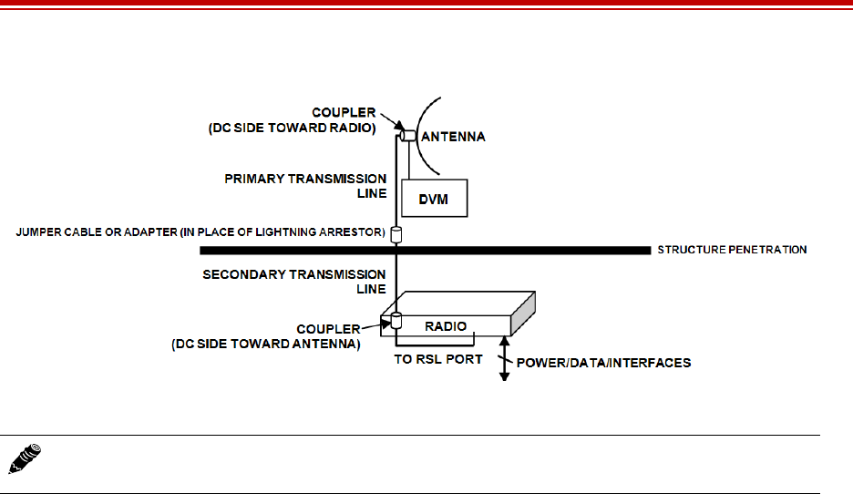
Exalt Installation and Management Guide
EX-i Series (TDD) Digital Microwave Radios
206501-019 101
2016-05-24
Figure 64 DC coupler interconnection
Note: After completing antenna alignment, remove the DC couplers and associated wiring at
both radio and antenna ends.

Exalt Installation and Management Guide
EX-i Series (TDD) Digital Microwave Radios
102 206501-019
2016-05-24
Troubleshooting
This section provides information regarding troubleshooting of common issues and alarms on these
radios. Exalt Digital Microwave Radio systems are designed by Exalt’s expert engineers with
extensive experience through multiple generations of microwave radio design. These new-generation
systems contain extensive diagnostic tools, alarm indications, and troubleshooting aids. And, as
compared to other systems in their class, are easier to install, maintain, and troubleshoot. The GUI
provides information to aid in troubleshooting (see Diagnostic Charts Page).
Contact Exalt Customer Care for further assistance with issues with your Exalt radio and with
suggestions on how the radio and documentation can be improved.
General Practices
Troubleshooting a microwave radio link can be a complex task. Approach troubleshooting as a process
of elimination, and first determine which portions of the system are operating properly.
In a vast majority of cases, failures or poor performance of microwave links is attributed to something
other than the microwave radio hardware. In this respect, the back-to-back bench test (see Back-to-
back Bench Testing) is very important to determine if radio hardware is operating properly and
eliminate many variables in the troubleshooting process.
If a back-to-back bench test fails, then the radio hardware is either broken or the radios are improperly
configured. Upgrade the radio to the most current release of firmware, and/or reset the radio to its
critical factory settings, following the quick start guide instructions and those in Configuration and
Management, helps to confirm if configuration issues cause failure. The most common issues with
microwave radio links are:
•An improperly terminated RF cable
•Multipath propagation
•RF interference
•Path obstruction
•Misaligned antenna
•Faulty antenna
•Improper grounding
•Insufficient link margin in the design/implementation
•Moisture in the transmission system (antenna feed and/or RF cable)
If the radio link has been operating without issues and is exhibiting new poor performance behavior or
becomes completely inoperative, the troubleshooting process should pay close attention to any
conditions that may have changed between the time when the system was working without issue and
the time when the issues started.
Also, it can be helpful to compare some performance parameters of the system before and after the
presence of issues. Often the source of the issues can be determined by thoughtful consideration of
changes, such as:
•Changes in weather, including high winds
•Changes made to the radio equipment, transmission system, or connected equipment
•New radio systems or electronic equipment the nearby radio or transmission system

Exalt Installation and Management Guide
EX-i Series (TDD) Digital Microwave Radios
206501-019 103
2016-05-24
•New construction nearby either end of the link, or along the path
•Tree growth, flooded fields, or changes in rivers/lakes along the path
Verify that configurations are set as follows:
•RF matches at each end of the link
•Bandwidth matches at each end of the link
•Link distance matches at each end of the link
•TDD Frame Length matches at each end of the link
•Endpoint Identifier is different at each end of the link (one end Radio A, one end Radio B)
•Ethernet interfaces are enabled, as desired
•AUX Ethernet is set for in-band or out-of-band NMS, as desired
•T1/E1 enabling matches at each end of the link
•Link security key matches at each end of the link
Also, in the design phase determine the optimum setting for the Bandwidth and TDD Frame Length
parameters for the given link distance, and provides guidance to the expected RF link performance, as
well as throughput, latency, and number of supported T1/E1 circuits.
Typical Indications of Issues
In many cases, microwave radio users do not notice changes or degradation to the radio system until
the radio system fails completely or becomes highly errored or significantly intermittent. However,
regular management of the radio system can help indicate changes in performance that have not yet
impacted user performance, but may impact performance at a later date if left unchecked or
unaddressed. The administrator can use this as an opportunity to be proactive and monitor the radio
link performance regularly, watching for unexplained or unexpected changes in performance and
trends in performance changes.
Most importantly, monitoring radio system RSL over time indicates the performance of the radio
system. Address any long-term drop in RSL and erratic or unsteady RSL. Some RSL changes are
expected and weather patterns and the related multipath can cause dramatic RSL changes resulting in
system outage. However, that outage should not occur at a significantly greater rate than the designed
long-term performance. Consult the path design engineer for more information about link reliability
expectations and anticipated RSL deviation.
In addition, regular inspection of the transmission system (RF cables and antennas) and paying close
attention to changes along the path, such as construction or tree height, or new microwave radio
installations nearby, can be extremely helpful and proactive.
When link performance is very poor, alarms on the radio front panel and within the radio’s
management system indicates particular failures. Consult this manual for more information on the
specific alarms and diagnostics, or contact Exalt Customer Care for assistance.
Exalt Customer Care is primarily motivated to determine if the radio hardware is faulty and require
return for repair, and to help execute an effective and efficient repair and return process for radio
terminals believed to be faulty. However, Exalt Customer Care provides advice regarding the total
radio system and RF path engineering and environment, and advises on troubleshooting.
End users should first contact the installer and/or designer of the system. In many cases, an in-depth
understanding of RF design is required, and on-site analysis and special test equipment, may be

Exalt Installation and Management Guide
EX-i Series (TDD) Digital Microwave Radios
104 206501-019
2016-05-24
necessary. Compared to phone support from Exalt Customer Care, troubleshooting is much more
expeditious if the professional installer and/or link designer examines the system and reviews the
management information in the GUI. In turn, if the professional installer and/or link designer contacts
Exalt Customer Care, the process to rectify the system is much more expedient due to the in-depth
knowledge related to the implementation and the RF environment.
Improper RF Cable Termination
Improper RF cable termination is a very common problem. In many cases, this is a problem that occurs
during installation and is not a problem that suddenly appears. However, if cables are moved or flexed,
especially near the termination points, and radio errors, changes in RSL, or other performance issues
occur, this is a certain sign of this issue.
Another relatively easy method to test for this condition is to decrease the output power of the radio
system (at each end, one end at a time). A poor RF cable termination may be reflecting too much RF
energy back into the radio system, and reducing output power reduces the reflected energy at a faster
rate than the transmitted energy towards the far end. Be careful not to reduce the output power to the
point where the radio’s threshold is reached. Typically, a reduction of just 3 to 6dB is enough to
determine if this is the issue. If the reduction of output power clears the error condition, this is the
likely cause.
Use a reflectometer or meter that can read VSWR at the operating frequency to identify poor
terminations as well as poor antenna feeds.
Multipath Propagation
Multipath propagation is a term that encompasses changes to the RF path, such as reflections and/or
refraction, causing partial or complete destruction of the radio signal, and thus excessive bit errors and/
or system outages.
Rapid changes in temperature, inversion layers, humidity, air pressure, water evaporation, as well as
standing water or moisture on objects along the path are all examples of changes that can cause
multipath propagation. New building construction near either end of the path or along the path can
cause new reflection characteristics.
If your system has been operating without issue and is suddenly experiencing issues that are
symptomatic of a certain time of day or related to change in climatic events or some of the external
factors listed above, this is likely the cause. Consult a professional RF path engineer in these cases.
Often, minor repositioning of the antennas at either or both ends can reduce or eliminate these
problems.
RF Interference
RF interference is usually indicative of another radio system nearby either end of your radio system or
aimed towards one or both ends of your radio system – usually at or near the same frequency and
usually with a similar signal level.
Other forms of RF interference also exist, such as electronic equipment placed close to the radio
chassis or transmitters that couple onto the cabling or grounding system of the radio. Microwave ovens
and wireless communication devices used near the equipment or cabling are examples of electronic
equipment interference.
Note: The Praxsym VSWR meter is an excellent tool for this purpose.

Exalt Installation and Management Guide
EX-i Series (TDD) Digital Microwave Radios
206501-019 105
2016-05-24
RF interference, like most other causes of problems, is indicated by significant bit errors and/or system
outages.
One means to determine presence of interference is the use of a spectrum analyzer that covers the same
range as the radio system. A professional RF engineer can use a spectrum analyzer to locate sources of
interference, measure these sources, and determine potential remedies to take to operate in the
presence of interference.
If a spectrum analyzer is not available, the radio’s RSL port can help determine RSL levels of
interfering signals. By turning the far-end radio off, the residual RSL measured by the radio indicates
the level of interference seen by the radio. It is possible that interference levels below that which can
be measured still have an impact on the radio system – especially if the radio system has low fade
margin or is using a high order modulation.
Exalt Digital Microwave Radios provides considerable flexibility to tune to different frequencies
across the bands within which they operate. This is the easiest method to use to try to avoid existing
interference. In addition, the occupied bandwidth of the radio can be reduced. This, along with re-
tuning, can be very effective, however throughput is reduced.
Repositioning the antenna and/or changing polarization, or upgrading the antenna to a higher gain,
and/or using a high-performance antenna, are all secondary means that can be used. It may be
necessary to perform combinations of both radio changes (retuning, occupied bandwidth reduction)
and antenna system changes (position, polarization, upgrade).
The EX-4.9i radio operates under licensed regulations. If interference is suspected, the local frequency
coordination organization, or other users of the spectrum should be consulted before re-tuning the
radio to a different frequency channel.
Path Obstruction
A path obstruction is defined as an object, such as a building or tree, impeding the proper path of the
radio system. If the system design was proper at the time of installation and issues arise at a later date,
an updated path profile and survey may be necessary to identify changes in path clearance.
Misaligned Antenna
At the time of initial installation, it is critical that the antennas at each end are properly aligned and that
the designed RSL is achieved. However, antennas may become misaligned due to high winds, changes
in the guy-wiring systems keeping the antenna mast stable, or loosening of the antenna mounting
hardware. A reduction in the RSL of the link is symptomatic of this condition, but this condition is not
the only condition that results in a reduction of RSL. However, if conditions occur where the antenna
alignment may be suspected, the mechanics must be inspected and the antennas realigned.
Faulty Antenna
A faulty antenna is rare, but is still a possibility. In some cases, the mechanics of the antenna feed can
get moisture inside, or a bad or weak connection in the pin and connector structure of the antenna may
occur. A VSWR measurement of the antenna connection can be made to verify this condition.
Note: Exalt Digital Microwave Radios operate in license-exempt bands. Microwave ovens,
wireless Internet devices and cordless phone technology may also use this frequency band. It
may be necessary to separate the radio chassis, cabling system and antenna from these
devices.

Exalt Installation and Management Guide
EX-i Series (TDD) Digital Microwave Radios
106 206501-019
2016-05-24
Improper Grounding
In addition to being a potential human safety issue, improper system grounding is a somewhat
common condition that can cause continuous bit errors or bit errors when metal objects come in
contact with the radio, transmission system, or racking system. If touching the radio causes errors,
grounding is the cause. It can be difficult to identify grounding problems, but a professional electrician
can normally inspect a system and identify if there are deficiencies in the grounding system.
Insufficient Link Margin
Ideally, the link was designed with enough link margin (fade margin) to allow for multipath
propagation and atmospheric fading and still remain reliable. In some cases, link margin is
compromised by economic factors, such as using low-cost RF cabling or lower-cost antennas that have
less gain or deficient performance compared to higher cost transmission system components. In some
cases, there may be antenna size restrictions that forced the design to not have the desired amount of
link margin.
If the link was designed with poor link margin, there are likely many cases of bit errors and outages.
The antenna system and transmission line can be upgraded to help reduce this. If the link design was
installed with sufficient margin, but RSL is reduced, the remaining link margin may no longer be
enough to maintain a reliable link. The causes of RSL reduction were previously described, but are
usually due to new path obstruction(s) or antenna misalignment due to wind or mechanical factors. The
antenna height or location can be changed to overcome new obstructions. Realignment of the antenna,
and/or improvement to mechanical structures can help overcome antenna misalignment.
Moisture in the Transmission System
If the connectors on cables and antennas and egress junctions are not properly weatherproofed,
moisture can get into the transmission system and cause significant error conditions and erratic
performance. In many cases, the transmission system must be replaced. A VSWR meter is one means
to identify such issues. Conduct physical inspections often. If changes to the weatherproofing (such as
cracking) are noticed, replace the weatherproofing before leakage occurs.
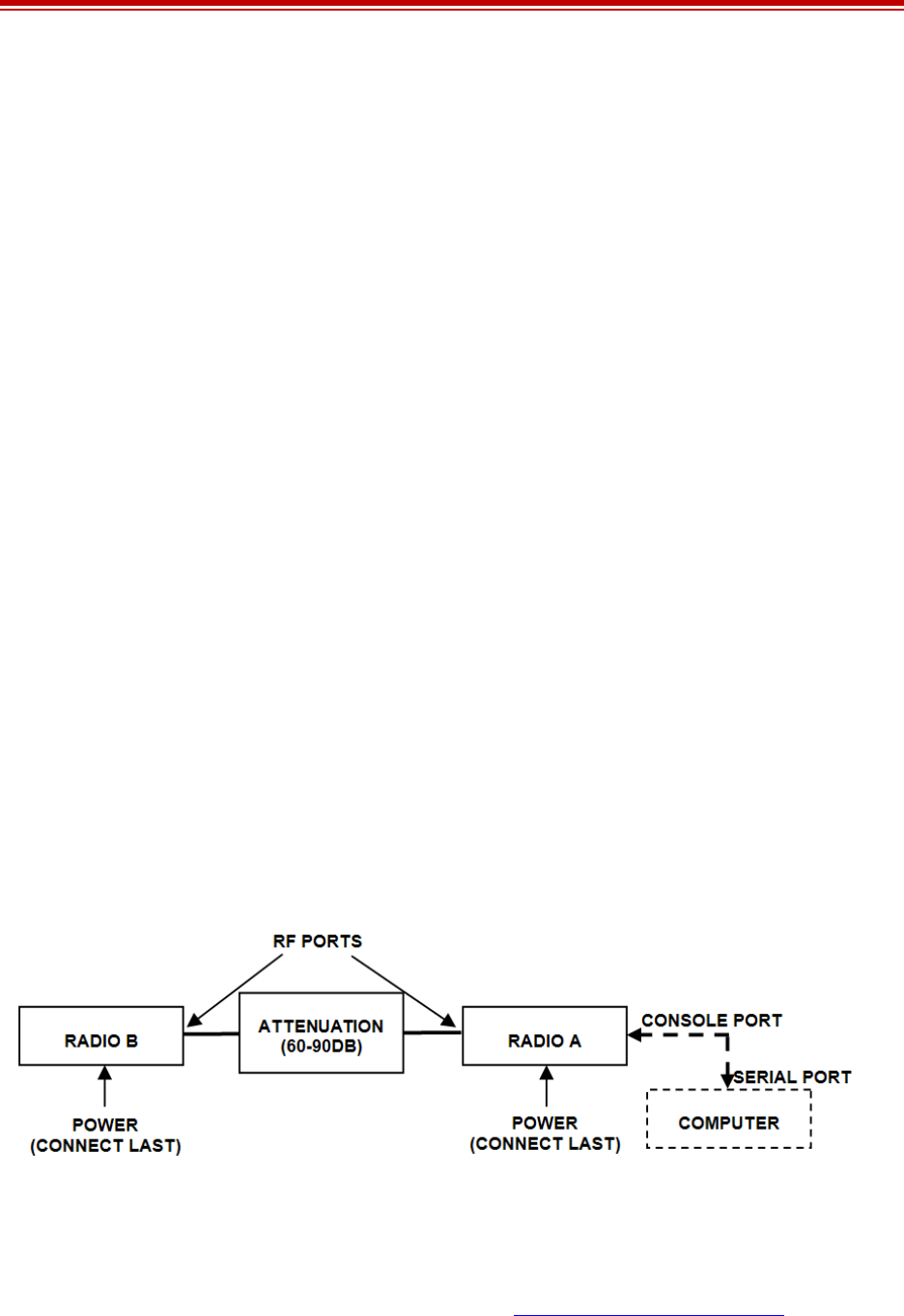
Exalt Installation and Management Guide
EX-i Series (TDD) Digital Microwave Radios
206501-019 107
2016-05-24
Back-to-back Bench Testing
Use back-to-back bench testing to test the radio before installation, pre-configure the radio and
connected equipment before installation, or in the troubleshooting process to identify if the radio
hardware is the source of a system issue. It is a critical process, and often required or highly desirable
for any installation or troubleshooting exercise. This section describes how to properly configure the
radio hardware and accessories for a proper back-to-back bench test.
For radio testing, there are two types of back-to-back configurations:
1Basic test (test general operation)
2Specification performance verification
Basic Test
The basic test is a simple test of radio functionality. It verifies that the radios are properly configured to
communicate to one another, and verifies general radio performance as operational.
For the basic test, the following items are needed:
•Radio pair
•Powering source
•RF interconnect cable(s) (any length – short is best)
•Fixed or variable attenuation, between 60 and 90dB (note: attenuation for basic test does not to be
calibrated or precise)
•Computer/terminal with either serial or Ethernet port
Connect the items as follows:
1Connect attenuation and (known-good) RF cable(s) between radio pair, shown in Figure 65.
2Configure one radio as Radio A; the other as Radio B
3Power on radio pair
Figure 65 Basic back-to-back bench test configuration
After connecting and powering on, observe the front panel LEDs to verify that the LINK and STATUS
LEDs are green. If so, the radios are communicating and all radio-related alarm conditions are normal.
It can be beneficial to have a computer to verify configuration in case of red LEDs or to pre-configure
the radio as desired for operation. Follow the instructions in Configuration and Management.

Exalt Installation and Management Guide
EX-i Series (TDD) Digital Microwave Radios
108 206501-019
2016-05-24
Specification Performance Verification
The specification performance verification is a more detailed test that allows you to verify that the
radio’s output power and threshold specifications are being met. This is typically a test that would only
be performed in a troubleshooting scenario, but can be performed before installation to provide a
detailed record or ensure radio performance before installation.
This test is identical to the basic test, but in place of the fixed attenuation, it requires the use of
calibrated variable attenuation, or a set of calibrated fixed attenuators, or a combination of both, adding
to a total attenuation value of 120dB, as measured at the operating frequency of the radio. In addition,
a volt meter or computer is also required.
Connect the system as shown in Figure 65, using the combination of fixed and variable attenuation
between the radio’s RF ports. Connect the volt meter to either radio’s RSL test point and associated
reference ground connection.
In this test, it is desirable to use pre-tested RF cables, known to be good, and the insertion loss is
known at the operating frequency. If the cables are short (6'/2m or less), you can estimate the loss,
including connectors, to be less than 1dB each. The estimate of cable loss is critical to the overall
confidence of the measurements made in this test.
There are two critical specifications that can be tested in this configuration:
•RF output power
•Radio receiver threshold
To measure transmitter output power, simply insert any value of attenuation between the radios
between 60 and 90dB. Ensure that both RF output power settings are at maximum. Use the volt meter
to measure RSL in both directions. The RSL measured value should match the appropriate value
according to the inserted attenuation, such as:
RSL = RF Output Power – cabling losses – total attenuation
Verify output power by adjusting output power using the Exalt GUI (in administration mode) and
evaluate the corresponding change to the RSL measurement.
For threshold testing, the key is to insert a measured amount of loss that is close to, but not exceeding
the radio’s specified system gain. System gain is the difference between RF output power and receiver
threshold. At your selected modulation and bandwidth settings, determine the specified threshold
performance, and choose a value of attenuation (including cable losses) that adds to roughly 5 to 15dB
less than the system gain.
For example, for the EX-2.4i, if the threshold for your measurement is -85dBm, the output power is
+27dBm, so the system gain is 112dB. Choose a value of total attenuation in the range of roughly 100–
105dB. Once this attenuation is inserted, verify RSL readings as in the first step, and then, using the
GUI, reduce radio output power in 1dB steps until the receiving radio (the one whose output power not
being adjusted) Link LED turns from green to yellow. This indicates that threshold has been reached.
At this point, verify the equation for system gain using the new output power level setting and verify
that the threshold performance is meeting or exceeding the published specification.
Note: Due to the variation of measurements and accuracies involved in this test, you may
read a measurement that is 1dB to as much as 2dB off of the expected value. It should be of
no concern unless the value is more than 3dB worse than expected.

Exalt Installation and Management Guide
EX-i Series (TDD) Digital Microwave Radios
206501-019 109
2016-05-24
Once threshold is verified in this direction, repeat the process in the opposite direction by adjusting RF
output power of the radio at the opposite end. Return the first radio to its original power setting before
adjusting the second radio.

Exalt Installation and Management Guide
EX-i Series (TDD) Digital Microwave Radios
110 206501-019
2016-05-24
General Compliance and Safety
The usage of radio transmission devices is subject to specific regulatory requirements governed by
regional legislation. In most cases, the specific device must be authorized for use in a given country
and must be installed and adjusted in accordance with specific radio-frequency settings and in a
manner that has been authorized specific to the device itself in accordance with the specific location of
the device. Some users may be completely or partially restricted from use of the device. Please consult
local governmental agency/agencies for regulatory requirements before use, or contact Exalt or your
Exalt authorized dealer for assistance.
Do not modify this device in any way without the express written consent of Exalt. Modification voids
the manufacturer warranty, and may also be illegal in accordance to government regulations. In
addition, there are no user-serviceable parts or assemblies inside the product housing. There may also
be voltages, signals, and mechanisms within the device that could be harmful to human safety.
The mounting of this device and associated peripherals and connections (inclusive of antenna mast,
antenna, cabling, egress, lightning protection devices, grounding, power, and so on) may be subject to
regional requirements for health and human safety. A qualified professional installer and an electrician
are highly recommended, and may be required by law.

Exalt Installation and Management Guide
EX-i Series (TDD) Digital Microwave Radios
206501-019 111
2016-05-24
Dynamic Frequency Selection
Dynamic Frequency Selection (DFS) may be required by regional legislation in some frequency bands
to avoid causing interference to radar systems. Prior to the start of any transmission, the device
equipped with DFS monitors the spectrum and is not permitted to transmit on a part of the spectrum
that is already in use for radar transmissions for a period of 30 minutes. During operation of the device,
the spectrum is continually monitored by the DFS to detect if radar begins transmission on a frequency
that is being used by the device to transmit on. If the DFS software detects radar, the device must move
off channel within a specified time period so that the device transmission does not interfere with the
radar transmission. The device equipped with DFS is required to stay off that part of the spectrum for a
minimum of 30 minutes, after which time the device may then check the spectrum for radar
transmissions and begin transmitting if no radar is detected.

Exalt Installation and Management Guide
EX-i Series (TDD) Digital Microwave Radios
112 206501-019
2016-05-24
Safety Notices
1Review this entire guide for important installation instructions BEFORE attempting to install this
product.
2This product is intended to be installed, used, and maintained by experienced telecommunications
personnel only.
3Employ a properly licensed or authorized electrician to install or evaluate/certify the installation of
all power and grounding related to the use of this equipment and all connected devices.
4The device(s) shall only be connected to AC power sources provided by the supplier or to DC
sources within the device specifications. Use a separate breaker circuit at the power source.
5Lightning, surge protection devices, and earth grounding are required for most installations to
ensure human safety. Consult a qualified electrician.
6Servicing of this device should be performed by authorized personnel only. Do not disassemble
this device. By opening or removing any covers you may expose yourself to hazardous energy
parts. Incorrect reassembly of this product can cause a malfunction, and/or electrical shock, when
the unit is subsequently used.
7Do not connect or disconnect the power connection to the device when the power supply is
plugged into an AC outlet. To connect, first connect the power connection to the device, and then
apply power (or plug in) at the outlet. To disconnect, disengage power at the outlet or unplug, and
then disconnect the direct connection to the device.
8Do not insert any object of any shape or size inside this product at any time, whether powered or
not. Objects may contact hazardous energy components that could result in a risk of fire or
personal injury.
9Liquids shall not come in contact with, or enter the inside of the device at any time.
10 Proper ventilation and/or airflow shall be provided surrounding the equipment. Items shall not
come in contact with heat-sinking materials. Ensure that ambient operational and storage
temperature specifications are maintained at all times.
11 Equipment is suitable for mounting on noncombustible surfaces only.
12 Do not move or alter the marking labels.
13 A CSU or similar isolating device is necessary between the equipment and the public
telecommunications network. The equipment has not been evaluated for direct connection to the
public telecommunications network.

Exalt Installation and Management Guide
EX-i Series (TDD) Digital Microwave Radios
206501-019 113
2016-05-24
Regulatory Notices
This section presents the Regulatory Compliance Regulations for your country.
4.9GHz Model
The EX-4.9i is a licensed-band product operating within Part 90 of the FCC regulations and RSS-111
of Industry Canada. These bands are specifically reserved for Public Safety applications and related
agencies, in accordance with these regulations.
Transmitter power reduction may be required, depending on transmission system gains and losses, in
accordance with instructions found in this appendix.
The transmitter power of the device must be reduced by 1 dB for every 1 dB that the antenna gain
exceeds 26 dBi (inclusive of transmission system losses).
United States Compliance
The EX-2.4i and EX-5i product families operate under FCC Rule Parts 15.247 and/or 15.407 as a
license-exempt device. The EX-4.9i products operate under FCC Rule Part 90 as a licensed device.
They may only be used as a point-to-point transmission device for fixed or temporary-fixed (non-
mobile) installations. The devices are subject to the following restrictions:
•Do not use external amplifiers to boost the power or overcome transmission system losses, unless
the specific amplifier/cable/antenna combination has expressly been authorized by the FCC. The
output power must never exceed +30 dBm.
•Cross-border transmissions are expressly prohibited, except with written permission from both the
FCC and the governing body of the neighboring country (Cofetel for Mexico; Industry Canada for
Canada).
•Use only parabolic dish antennas or directional flat-panel antennas. No other types of antennas
(omni-directional, yagi, and so on) are authorized. Parabolic dishes of either grid or solid type are
allowed. Maximum mid-band gain of each type of antenna certified is:
– EX-2.4i models:
–Parabolic dish: 30.3 dBi (6'/1.8m diameter)
–Directional flat panel: 20.5 dBi (~2'/61cm square)
– EX-4.9i models:
–Parabolic dish: 26dBi (larger gains are allowed, with Tx power reduction)
–Directional flat panel: 26 dBi (larger gains are allowed, with Tx power reduction)
–EX-5i models:
–Parabolic dish: 37.9 dBi (6'/1.8m diameter)
–Directional flat panel: 28 dBi (~2'/61cm square)

Exalt Installation and Management Guide
EX-i Series (TDD) Digital Microwave Radios
114 206501-019
2016-05-24
Federal Communications Commission (FCC), United States
The device is allowed to be used provided it does not cause interference to other devices. It is not
guaranteed to provide protection against interference from other electronic and radio devices.
The system has been tested and found to comply with the limits of a Class B digital device, pursuant to
Part 15 of the FCC Rules. These limits are designed to provide reasonable protection against harmful
interference in a residential installation. This equipment generates uses and can radiate radio frequency
energy and, if not installed and used in accordance with the instructions, may cause harmful
interference to radio communications. However, there is no guarantee that interference will not occur
in a particular installation. If this equipment does cause harmful interference to radio or television
reception, which can be determined by turning the equipment off and on, the user is encouraged to try
to correct the interference by one of more of the following measures:
•Reorient or relocate the receiving antenna.
•Increase the separation between the equipment and receiver.
•Connect the equipment into an outlet on a circuit different from that to which the receiver is
connected.
•Consult the dealer or an experienced radio/TV technician for help.
Shielded cables and I/O cords must be used for this equipment to comply with the relevant FCC
regulations.
Changes or modifications not expressly approved in writing by Exalt may void the user’s authority to
operate this equipment.
This device must be professionally installed.
To comply with regulations, the output power of this device may need to be adjusted in accordance to
the associated transmission system. See RF Output Power Setting for details.
The antenna associated with EX-2.4i family shall be mounted in a location that is at least 10 feet away
from humans that may be subject to long-term or continuous exposure. The antenna associated with
the EX-5i family shall be mounted in a location that is at least 10’/3m away from humans that may be
subject to long-term or continuous exposure.
Important: Where required by regional regulations, DFS is enabled by the system keys and cannot be
disabled.
Canada Compliance
The EX-2.4i and EX-5i models operate under RSS-210 of Industry Canada regulations. The EX-4.9i
model operates under RSS-111 of Industry Canada regulations. Operation is subject to the following
conditions, unless express permission is granted by Industry Canada to operate in a different manner:
Note: The 5GHz model is approved under FCC Rule Part 15.407(b)(4)(ii) for antenna gains greater
than 10dBi.
The 5GHz model cannot be manufactured, marketed, or sold after March 2, 2018 unless it is re-
certified under FCC Rule Part 15.407(b)(4)(i).
Check with Exalt Wireless for status of re-certification.

Exalt Installation and Management Guide
EX-i Series (TDD) Digital Microwave Radios
206501-019 115
2016-05-24
•External amplifiers cannot be used to boost the power or to overcome transmission system losses,
unless the specific amplifier/cable/antenna combination is expressly authorized by Industry
Canada.
•Cross-border transmissions are expressly prohibited, except with written permission from both
Industry Canada and the governing body of the neighboring country (FCC for USA)
•Only parabolic dish antennas or directional flat-panel antennas may be used. No other types of
antennas (omni-directional, yagi, and so on) are authorized. Parabolic dishes of either grid or solid
type are allowed. Maximum gain of each type of antenna allowed is:
– EX-2.4i models:
–Parabolic dish: 30.3 dBi (6'/1.8m diameter)
–Directional flat panel: 20.5 dBi (~2'/61cm square)
– EX-4.9i models:
–Parabolic dish: 26 dBi (larger gains are allowed with Tx power reduction)
–Directional flat panel: 26 dBi (larger gains are allowed with Tx power reduction)
–EX-5i models:
–Parabolic dish: 37.9 dBi (6'/1.8m diameter)
–Directional flat panel: 28 dBi (~2'/61cm square)
Industry Canada (IC), Canada
This device complies with RSS-210 of Industry Canada. Operation is subject to the following two
conditions:
1this device may not cause interference, and
2this device must accept any interference, including interference that may cause undesired
operation of the device.
Antennas Supported in Canada
The EX-2.4i is designed to operate with the antennas listed in Table 10, which have a maximum gain
of 30.3 dBi. Antennas not included in the list or having a gain greater than 30.3 dBi are prohibited for
use with this device. The required antenna impedance is 50 Ohms.
The antenna associated with the EX-2.4i family shall be mounted in a location that is at least 10 feet
away from humans that may be subject to long-term or continuous exposure.
The EX-5i family has been designed to operate with the antennas listed in Table 11, which have a
maximum gain of 37.9 dBi. Antennas not included in the list or having a gain greater than 37.9 dBi are
prohibited for use with this device. The required antenna impedance is 50 Ohms.
The antenna associated with the EX-5i family shall be mounted in a location that is at least 10’/3m
away from humans that may be subject to long-term or continuous exposure.
Important: Where required by regional regulations, DFS is enabled by the system keys and cannot be
disabled.

Exalt Installation and Management Guide
EX-i Series (TDD) Digital Microwave Radios
116 206501-019
2016-05-24
Europe and ITU Country Compliance
All of these permitted devices must be professionally installed. They can only be used as a point-to-
point transmission device for fixed or temporary-fixed (non-mobile) installations.
The EX-2.4i product family operates under EN 300 328 rules as a license-exempt device. The 2.4 GHz
band is not yet harmonized in all countries recognizing ETSI or ITU band assignments. There is a
+20dBm EIRP limit applied to this band. Transmitter power must be adjusted accordingly with respect
to the RF cabling losses and antenna gains associated with each terminal.
The EX-4.9i devices are currently not permitted in any EU member or affiliate countries.
The EX-5i product family operates under EN 301 893 and EN 302 502 rules as a license-exempt
device.
The EX-5i product family complies with ETS 301 893 for the 5.3 and 5.47 GHz bands for license-
exempt use for most countries recognizing ETSI or ITU band assignments. This band is not yet
harmonized for all countries recognizing ETSI or ITU band assignments. These bands require
Dynamic Frequency Selection (DFS) and Transmitter Power Control (TPC) for radar-detection and
avoidance. There is a +30dBm EIRP limit applied to this band. Transmitter power must be adjusted
accordingly with respect to the RF cabling losses and antenna gains associated with each terminal.
The EX-5i product family complies with ETS 302 502 for the 5.8 GHz band. This band is not yet
harmonized for all countries recognizing ETSI or ITU band assignments. Consult the individual
country regulations or your Exalt Wireless representative for details. This band requires DFS and TPC
for radar-detection and avoidance. There is a +33dBm EIRP limit for use of the 10 MHz BW setting,
and a +36dBm EIRP limit for use of the 20 MHz BW setting. Some countries limit the EIRP to +5dBm
for all bandwidths in this band.
All models comply with the requirements for CE Mark (EN 60950-1 and IEC 60950-1) and EMC
(EN 301 489-17). No substitutions shall be made, and all wiring and grounding instructions contained
in this manual must be followed to ensure safety in accordance to the standards and local rules.
Note: Do not use external amplifiers to boost the power or overcome transmission system
losses, unless the specific amplifier/cable/antenna combination has expressly been authorized
by the specific country regulations. The output power must never exceed that specified in
Specifications.

Exalt Installation and Management Guide
EX-i Series (TDD) Digital Microwave Radios
206501-019 117
2016-05-24
Regulatory Compliance
As of this printing, Exalt Wireless, Inc. has approvals for the products that are covered by this manual,
as indicated in Table 12. If your application or country is not listed, check with your Sales
Representative for the current status.
Table 12 Product approvals
Country EX-2.4i Series EX-4.9i Series EX-5i Series,
5.3 GHz EX-5i Series,
5.4 GHz EX-5i Series,
5.8 GHz
Austria
Australia
Belgium
Canada
Cyprus
Czech Republic
Denmark
Estonia
Finland
France
Germany
Ghana
Great Britain
Hungary
Iceland
Ireland
Italy
Liechtenstein
Lithuania
Luxembourg
Malta
Mexico
Netherlands
Norway
Philippines
Poland
Portugal

Exalt Installation and Management Guide
EX-i Series (TDD) Digital Microwave Radios
118 206501-019
2016-05-24
Romania
Slovak Republic
Slovenia
South Korea
Sweden
Switzerland
Turkey
United States
Table 12 Product approvals (Continued)
Country EX-2.4i Series EX-4.9i Series EX-5i Series,
5.3 GHz EX-5i Series,
5.4 GHz EX-5i Series,
5.8 GHz
Exalt Installation and Management Guide
EX-i Series (TDD) Digital Microwave Radios
206501-019 119
2016-05-24
Regulatory Domain Keys
Exalt radios are designed to allow the professional installer to select frequency bands, determine signal
bandwidths, tune center frequencies, limit output power, and enable or disable DFS options as
permitted by regional regulations. For models with the Regulatory Domain Key (RDK) feature, the
radios ship with the RDK information empty and the radio cannot be enabled without a valid key. The
partner, distributor, or installer is responsible for installing the RDK based on the final installation
country of the radio. Exalt issues RDK information to their distributors when ship-to country
information is provided. Consult your local Exalt distributor or reseller to obtain the RDK.
RDK 053A8 is supported in firmware 4.0.0 and later, and is the same as ETSI 053A4 with the 40 MHz
bandwidth added in UNII bands.
Countries are assigned to different regulatory domains based on current regulatory requirements. Each
regulatory domain has the parameters set to ensure that when the radio is turned on, the default settings
are complaint for local laws.
Regulatory Domain Keys are assigned by regulatory domain based on the local regulations.
Caution: It is critical that the RDK be set to the correct default setting so that the local
regulations for the installation requirements are met.
Table 13 Regulatory Domain Keys
Regulatory Domain
Key Name Frequency
Band(s) Countries
024A0 2.4GHz USA, Canada, EU, Ghana, Mexico
049A0 4.9GHz USA, Canada
053A0 5.3GHz,
5.4GHz,
5.8GHz
USA (prior to July 20, 2007), Canada (prior to May 08, 2008),
Singapore, Philippines
053A1 5.3GHz,
5.4GHz,
5.8GHz
USA (after July 20, 2007), Canada (after May 08, 2008)
053A2 5.8GHz China
053A3 5.3GHz,
5.8GHz Mexico
053A4 5.3GHz,
5.4GHz,
5.8GHz
EU, Ghana
053A5 5.4GHz,
5.8GHz Australia
053A6 5.3GHz,
5.4GHz,
5.8GHz
Philippines
053A7 5.3GHz
5.4GHz
5.8GHz
Unrestricted (for countries without specific band and/or DFS
regulations)
053A8 5.3GHz
5.4GHz
5.8GHz
EU, adding 40MHz bandwidth channel support for 5.3GHz and
5.4GHz bands

Exalt Installation and Management Guide
EX-i Series (TDD) Digital Microwave Radios
120 206501-019
2016-05-24
EIRP Limits for the United States and Canada
EX-2.4i EIRP for the USA and Canada
For EX-2.4i models, the maximum EIRP allowed is +52.2 dBm. The maximum conducted power of
the radio is +27 dBm for Mode 1 and +24 dBm for Mode 2. The following formula is used to
determine the output power:
P = 30 – [(G-6)/3] + L
where:
EX-4.9i EIRP for the USA and Canada
For the EX-4.9i models, within the 4940–4990 MHz band, the maximum EIRP allowed is +50dBm.
The maximum output power of the radio shall never exceed +24dBm.
For the EX-4.9i models, the transmit power must be reduced from maximum (+24dBm for 20MHz
BW; +22dBm for 10MHz) by 1 dB for every 1dB that the antenna gain exceeds 26dBi (including
transmission system losses)
EX-5i Series EIRP for the US and Canada
5250–5350 MHz Band
For EX-5i models within the 5250–5350 MHz band, the maximum EIRP is 30 dBm. The maximum
output of the radio is +13 dBm.
P = 30 – G + L
where:
Note: The professional installer is responsible to ensure that RF output power is properly
adjusted to not exceed the regulatory limit.
P = Maximum transmitter output Power of radio, in dBm.
G = Specified gain of antenna, in dBi, from 2400 to 2483.5 MHz.
L = Total transmission system losses of all elements between the radio’s RF connector and the
antenna’s RF connector (all cables, connectors, and lightning suppressors), in dB, as specified
or measured between 2400 and 2483.5 MHz.
P = Maximum transmitter output power of radio, in dBm.
G = Specified gain of antenna, in dBi, from 5250 to 5350 MHz.
L = Total transmission system losses of all elements between the radio’s RF connector and the
antenna’s RF connector (all cables, connectors, lightning suppressors), in dB, as specified
or measured between 5250 and 5350 MHz.

Exalt Installation and Management Guide
EX-i Series (TDD) Digital Microwave Radios
206501-019 121
2016-05-24
5470–5725 MHz Band
For EX-5i models within the 5470–5725 MHz band, the maximum EIRP allowed is 30 dBm. The
maximum output power of the radio is +13 dBm.
P = 30 – G + L
where:
5725–5850 MHz Band
For the EX-5i models within the 5725–5850 MHz band, the maximum EIRP allowed is 61.9 dBm. The
maximum output power of the radio is +24 dBm in Mode 1 and +21 dBm in Mode 2.
P = 61.9 – G + L
where:
P = Maximum transmitter output power of radio, in dBm.
G = Specified gain of antenna, in dBi, from 5470 to 5725 MHz.
L = Total transmission system losses of all elements between the radio’s RF connector and the
antenna’s RF connector (all cables, connectors, lightning suppressors), in dB, as specified
or measured between 5470 and 5725 MHz.
P = Maximum transmitter output power of radio, in dBm.
G = Specified gain of antenna, in dBi, from 5725 to 5850 MHz.
L = Total transmission system losses of all elements between the radio’s RF connector and the
antenna’s RF connector (all cables, connectors, lightning suppressors), in dB, as specified
or measured between 5725 and 5850 MHz.

Exalt Installation and Management Guide
EX-i Series (TDD) Digital Microwave Radios
122 206501-019
2016-05-24
EIRP Limits for the European Union and ITU Countries
The countries that are covered by this Regulatory Domain are: Austria, Belgium, Cyprus, Czech
Republic, Denmark, Estonia, Finland, France, Germany, Ghana, Great Britain, Greece, Hungary,
Iceland, Ireland, Italy, Latvia, Liechtenstein, Lithuania, Luxembourg, Malta, Norway, Poland,
Portugal, Slovak Republic, Slovenia, Spain, Sweden, Netherlands, Switzerland, and Turkey.
•Use only parabolic dish antennas or directional flat-panel antennas. No other types of antennas
(omni-directional, yagi, and so on) are authorized. Parabolic dishes of either grid or solid type are
allowed. Maximum mid-band gain of each type of antenna certified is:
– EX-2.4i models:
–Parabolic dish: 30.3 dBi (6'/1.8m diameter)
–Directional flat panel: 20.5 dBi (~2'/61cm square)
–EX-5i models:
–Parabolic dish: 37.9 dBi (6'/1.8m diameter)
–Directional flat panel: 28 dBi (~2'/61cm square)
EX-2.4i-Series EIRP
For EX-2.4i models within the 2400–2483.5 MHz band, the maximum EIRP allowed is summarized in
Table 14. The maximum output power of the radio is +27dBm in Mode 1 and +24dBm in Mode 2.
P = ME – G + L
where:
Note: The professional installer is responsible to ensure that RF output power is properly
adjusted to not exceed the regulatory limit.
P = Maximum transmitter output power of radio, in dBm.
ME = Maximum EIRP, as specified in Table 14.
G = Specified gain of antenna, in dBi, from 2400 to 2483.5 MHz.
L = Total transmission system losses of all elements between the radio’s RF connector and
the antenna’s RF connector (all cables, connectors, lightning suppressors), in dB, as
specified or measured between 2400 and 2483.5 MHz.
Table 14 EU and ITU Country-Specific EIRP Levels for the EX-2.4i Series
Country Maximum EIRP
Austria 20 dBm
Belgium 20 dBm
Cyprus 20 dBm
Czech Republic 20 dBm
Denmark 20 dBm
Estonia 20 dBm
Finland 20 dBm

Exalt Installation and Management Guide
EX-i Series (TDD) Digital Microwave Radios
206501-019 123
2016-05-24
EX-5i Series EIRP
Table 15 summarizes the maximum power by band and country for EX-5i Series radios.
5250–5350 MHz band
For EX-5i models within the 5250–5350 MHz band, the maximum EIRP is specified in Table 15. The
maximum output of the radio is +13 dBm.
P = ME – G + L
where:
France 20 dBm
Germany 20 dBm
Great Britain 20 dBm
Hungary 20 dBm
Iceland 20 dBm
Ireland 20 dBm
Italy 20 dBm
Liechtenstein 20 dBm
Lithuania 20 dBm
Malta 20 dBm
Netherlands 20 dBm
Norway 20 dBm
Poland 20 dBm
Portugal 20 dBm
Romania 20 dBm
Slovak Republic 20 dBm
Slovenia 20 dBm
Sweden 20 dBm
Switzerland 20 dBm
Turkey 20 dBm
P = Maximum transmitter output power of radio, in dBm.
ME = Maximum EIRP, as specified in Table 15.
G = Specified gain of antenna, in dBi, from 5250 to 5350 MHz.
L = Total transmission system losses of all elements between the radio’s RF connector and
the antenna’s RF connector (all cables, connectors, lightning suppressors), in dB, as
specified or measured between 5250 and 5350 MHz.
Table 14 EU and ITU Country-Specific EIRP Levels for the EX-2.4i Series (Continued)
Country Maximum EIRP

Exalt Installation and Management Guide
EX-i Series (TDD) Digital Microwave Radios
124 206501-019
2016-05-24
5470–5725 MHz band
For EX-5i models within the 5470–5725 MHz band, the maximum EIRP allowed is specified in
Table 15. The maximum output power of the radio is +13 dBm.
P = ME – G + L
where:
5725–5850 MHz band
For EX-5i models within the 5725–5850 MHz band, the maximum transmit power with respect to
specific country EIRP regulations is determined based on the channel bandwidth. The EIRP power
limit is specified in Table 15. The Exalt EX-5i series radios maximum transmitter conducted power is
+24 dBm. Use the following equation to determine the maximum transmitter power for the radio:
P = ME – G + L
where:
P = Maximum transmitter output power of radio, in dBm.
ME = Maximum EIRP, as specified in Table 15.
G = Specified gain of antenna, in dBi, from 5470 to 5725 MHz.
L = Total transmission system losses of all elements between the radio’s RF connector and
the antenna’s RF connector (all cables, connectors, lightning suppressors), in dB, as
specified or measured between 5470 and 5725 MHz.
P = Maximum transmitter output power of radio, in dBm.
ME = Maximum EIRP, as specified in Table 15.
G = Specified gain of antenna, in dBi, from 5725 to 5850 MHz.
L = Total transmission system losses of all elements between the radio’s RF connector and
the antenna’s RF connector (all cables, connectors, lightning suppressors), in dB, as
specified or measured between 5725 and 5850 MHz.
Table 15 EU and ITU Country Specific EIRP Levels for EX-5i Series
Country Maximum EIRP
5.3 GHz band Maximum EIRP
5.4 GHz band
Maximum EIRP
5.8 GHz band
(BW dependent)a
Austria 23 dBm 30 dBm 5 dBm
Belgium 30 dBm
Cyprus 23 dBm 30 dBm
Czech Republic 30 dBm
Denmark 23 dBm 30 dBm 33/36 dBm
Estonia 23 dBm 30 dBm
Finland 23 dBm 30 dBm
France 23 dBm 30 dBm 33/36 dBm
Germany 23 dBm 30 dBm 33/36 dBm
Ghana 23 dBm 30 dBm 33/36 dBm

Exalt Installation and Management Guide
EX-i Series (TDD) Digital Microwave Radios
206501-019 125
2016-05-24
Great Britain 23 dBm 30 dBm 33/36 dBm
Hungary 23 dBm 30 dBm 33/36 dBm
Iceland 23 dBm 30 dBm 33/36 dBm
Ireland 23 dBm 30 dBm 33/36 dBm
Italy 23 dBm 30 dBm 33/36 dBm
Liechtenstein 23 dBm 30 dBm 5 dBm
Lithuania 23 dBm 30 dBm 33/36 dBm
Luxembourg 23 dBm 30 dBm
Netherlands 23 dBm 30 dBm 33/36 dBm
Norway 23 dBm 30 dBm 33/36 dBm
Poland 23 dBm 30 dBm 33/36 dBm
Portugal 23 dBm 30 dBm 5 dBm
Romania 23 dBm 30 dBm 33/36 dBm
Slovak Republic 23 dBm 30 dBm 5 dBm
Slovenia 33/36 dBm
Sweden 23 dBm 30 dBm 33/36 dBm
Switzerland 23 dBm 30 dBm 5 dBm
Turkey 23 dBm 30 dBm 33/36 dBm
a. If the output power is designated as 33/36 dBm, the EIRP is limited to 33 dBm for 10 MHz bandwidth
transmissions and 36 dBm for 20 MHz bandwidth transmissions.
Table 15 EU and ITU Country Specific EIRP Levels for EX-5i Series (Continued)
Country Maximum EIRP
5.3 GHz band Maximum EIRP
5.4 GHz band
Maximum EIRP
5.8 GHz band
(BW dependent)a

Exalt Installation and Management Guide
EX-i Series (TDD) Digital Microwave Radios
126 206501-019
2016-05-24
EIRP Limits for Australia
EX-5i Series EIRP for Australia
5470–5725 MHz Band
For EX-5i models within the 5470–5725 MHz band, the maximum EIRP allowed is 30 dBm. The
maximum output power of the radio is +13 dBm.
P = 30 – G + L
where:
5725–5850 MHz Band
For the EX-5i models within the 5725–5850 MHz band, the maximum EIRP allowed is 36 dBm. The
maximum output power of the radio is +24 dBm in Mode 1 and +21 dBm in Mode 2.
P = 36 – G + L
where:
Note: The professional installer is responsible to ensure that RF output power is properly
adjusted to not exceed the regulatory limit.
Note: Australian regulations have a no-transmit band from 5600–5650 MHz, adjust the
transmitter to avoid this range.
P = Maximum transmitter output power of radio, in dBm.
G = Specified gain of antenna, in dBi, from 5470 to 5725 MHz.
L = Total transmission system losses of all elements between the radio’s RF connector and
the antenna’s RF connector (all cables, connectors, lightning suppressors), in dB, as
specified or measured between 5470 and 5725 MHz.
P = Maximum transmitter output power of radio, in dBm.
G = Specified gain of antenna, in dBi, from 5725 to 5850 MHz.
L = Total transmission system losses of all elements between the radio’s RF connector and
the antenna’s RF connector (all cables, connectors, lightning suppressors), in dB, as
specified or measured between 5725 and 5850 MHz.
Exalt Installation and Management Guide
EX-i Series (TDD) Digital Microwave Radios
206501-019 127
2016-05-24
Declaration of Conformity to the R&TTE Directive
1999/5/EC
For 2.4 GHz radios, the following standards were applied:
•Radio: EN 300 328-1, EN 300 328-2
•EMC: EN 301 489-1, EN 301 489-17
•Safety: EN 60950, IEC 60950, IEC 60950-1
For 5 GHz radios, the following standards were applied:
•Radio: EN 301 893, EN 302 502
•EMC: EN 301 489-1, EN 301 489-17
•Safety: EN 60950-1, IEC 60950-1
English: This equipment is in compliance with the essential requirements and other relevant
provisions of Directive 1999/5/EC.
Deutsch: Dieses Gerät entspricht den grundlegenden Anforderungen und den weiteren
entsprecheneden Vorgaben der Richtlinie
1999/5/EU.
Dansk: Dette udstyr er i overensstemmelse med de væsentlige krav og andre relevante
bestemmelser i Directiv 1999/5/EF.
Español: Este equipo cumple con los requisitos esenciales asi como con otras disposiciones de
la Directive 1999/5/EC.
Français: Cet appareil est conforme aux exigencies essentialles et aux autres dispositions
pertinantes de la Directive 1999/5/EC.
Íslenska: Þessi búnaður samrýmist lögboðnum kröfum og öðrum ákvæðum tilskipunar 1999/5/
ESB.
Italiano: Questo apparato é conforme ai requisiti essenziali ed agli altri principi sanciti dalla
Direttiva 1999/5/EC.
Nederlands: Deze apparatuur voldoet aan de belangrijkste eisen en andere voorzieningen van
richtlijn 1999/5/EC.
Norsk: Dette utstyret er i samsvar med de grunnleggende krav og andre relevante
bestemmelser i EU-directiv 1999/5/EC.
Português: Este equipamento satisfaz os requisitos essenciais e outras provisões da Directiva
1999/5/EC.
Suomalainen: Tämä laite täyttää direktiivin 1999/5/EY oleelliset vaatimukset ja on siinä asetettujen
muidenkin ehtojen mukainen.
Svenska: Denna utrustning är i överensstämmelse med de väsentliga kraven och andra relevanta
bestämmelser i Direktiv 1999/5/EC.

Exalt Installation and Management Guide
EX-i Series (TDD) Digital Microwave Radios
128 206501-019
2016-05-24
The following CE mark is affixed to the product:
EU WEEE
Exalt is committed to meeting the requirements of the European Union’s Waste Electrical and
Electronic Equipment (WEEE) Directive. The Directives require producers of electrical and electronic
equipment to finance the take-back for re-use or recycling of their products placed on the EU market
after 13 August 2005.
Exalt products that are within the scope of the Directives are labeled with a crossed-out "wheelie-bin"
symbol as required by the Directives. This indicates that the product was placed on the market after 13
August 2005 and that end-users should segregate the product from other wastes at end-of-life.
The WEEE Directives are being implemented in each of the 28 EU and European Economic Area
(EAA) countries through national legislation. This has resulted in considerable variation in the detailed
requirements across the EU, many of which require presence in the EU. As a result, Exalt’s WEEE
compliance approach is to require the distributors and/or resellers in the EU to comply with each
country’s national legislation by registration of the distributor or reseller as the producer and for the
reseller/distributor to carry out and fulfill the legislative requirements of each national compliance
scheme.
Below is the crossed out wheelie bin symbol as required by the WEEE Directive.
EU RoHS
RoHS is the acronym used to refer to the European Union (EU) Directive 2002/95/EC on the
Restriction of the use of certain hazardous substances in electrical and electronic equipment.
Hazardous materials are those chemicals and substances that are legislatively, market, or customer
banned or restricted for use in products and/or manufacturing. There are six (6) RoHS substances:
lead (Pb), cadmium (Cd), mercury (Hg), hexavalent chromium (Cr+6), polybrominated biphenyls
(PBB) and polybrominated diphenylethers (PBDE). Other countries may be introducing legislation
that results in similar restrictions of hazardous substances. Many Exalt products will continue to use
lead-based solder under the exemption allowed for network infrastructure equipment. Small amounts
of lead, cadmium, mercury, hexavalent chromium, PBB, and PBDE can also be found in a few
electrical and electrical components.

Exalt Installation and Management Guide
EX-i Series (TDD) Digital Microwave Radios
206501-019 129
2016-05-24

Exalt Installation and Management Guide
EX-i Series (TDD) Digital Microwave Radios
130 206501-019
2016-05-24
END USER AGREEMENT
(including Limited Hardware Warranty, Software License and RMA Procedure)
THIS IS AN AGREEMENT BETWEEN YOU (AS ORIGINAL END USER PURCHASER OF AN EXALT PRODUCT)
AND EXALT WIRELESS, INC. ("EXALT"). THE END USER AGREEMENT APPLICABLE TO YOUR EXALT
PRODUCT IS THE END USER AGREEMENT THAT IS PRE-LOADED ON THE EXALT PRODUCT, OR IF NONE IS
PRE-LOADED, IT IS THE END USER AGREEMENT AVAILABLE ON THE EXALT WEBSITE @
WWW.EXALTCOM.COM/EULA ON THE DATE OF YOUR PURCHASE OF THE EXALT PRODUCT OR
OTHERWISE DIRECTLY AVAILABLE FROM EXALT UPON REQUEST. BY ACCEPTING THIS AGREEMENT OR
BY USING THE EXALT PRODUCT WITH OR FOR WHICH THIS AGREEMENT IS PROVIDED ("PRODUCT"),
YOU ARE AGREEING TO ALL OF THE BELOW TERMS AND CONDITIONS. IF YOU DO NOT AGREE WITH
THESE TERMS AND CONDITIONS, YOU SHOULD NOT USE THE PRODUCT AND PROMPTLY RETURN IT TO
YOUR PLACE OF PURCHASE FOR A REFUND. "YOU" MEANS THE LEGAL END USER ENTITY THAT
PURCHASED THE PRODUCT FOR ITS OWN USE.
1Exalt Limited Hardware Warranty
a. Exalt warrants solely to the original purchaser ("Purchaser") that the Exalt hardware product
that this Agreement is provided with or for (the "Hardware Product") will substantially
conform in all material respects to the relevant Exalt published specifications that apply at the
time of manufacture of such Hardware Product for two (2) years from the date of purchase of
Hardware Product by Purchaser (the "Warranty Period"). Proof-of-purchase in the form of an
invoice, payment of invoice, or delivery waybill must be supplied, if requested by Exalt, in
case of any dispute of warranty start date.
b. In the event Purchaser notifies Exalt during the Warranty Period of a defective Hardware
Product (material nonconformance with the published specifications), Exalt shall within the
Warranty Period, at its own option either: (A) use reasonable efforts to remedy any
reproducible Hardware Product defect covered by this limited warranty within a reasonable
period of time; (B) replace the defective Hardware Product with a functionally equivalent
product (repair parts and products may be either reconditioned or new, but, if reconditioned,
shall be of the same quality as new parts or products); or (C) if Exalt determines that it is
unable to repair or replace such Hardware Product, Exalt (or its applicable reseller) will refund
to Purchaser the amount actually paid by Purchaser for the applicable Hardware Product. All
replaced parts and products become the property of Exalt.
c. The Exalt warranty does not cover any defective Hardware Product that (i) is subject to the
exclusions set forth below in Section 3; (ii) cannot be demonstrated to have a defect of the
types of defects covered by the Exalt warranty, or (iii) Purchaser is unable to provide adequate
information describing how the Hardware Product failed that would allow Exalt to determine
that the defect is covered by the Exalt warranty. Any Hardware Product that is returned by the
Purchaser to Exalt and Exalt determines that such product is not covered by the Exalt
warranty, will be, at Purchaser's option and expense (including any applicable shipping,
handling, evaluation, repair, replacement and disposal fees), either be: (a) returned to
Purchaser in the state received, (b) repaired or replaced, as applicable, and returned to
Purchaser, or disposed of in accordance with Purchaser's instructions. Repaired or replaced
Hardware Product will be warranted for the remainder of the original Warranty Period, but not
less than ninety (90) days.

Exalt Installation and Management Guide
EX-i Series (TDD) Digital Microwave Radios
206501-019 131
2016-05-24
2Warranty Registration
In order to facilitate warranty service and communication with Exalt, Exalt recommends that the Purchaser
registers the Hardware Product with Exalt promptly following the Hardware Product purchase by providing
to Exalt the requested registration information. Product registration may be performed by completing and
submitting the product registration form on www.exaltcom.com/ProductRegistration.
3Limited Hardware Warranty Exclusions
This limited warranty will not apply to: (A) any Hardware Product that: (i) has been modified or
altered by any party other than Exalt; (ii) has been subject to accident, misuse, neglect, or
mistreatment; (iii) has been damaged during installation of the Hardware Product; (iv) has been
damaged by failure of Purchaser or its agents to follow Exalt's instructions or specifications; (v)
has been damaged by the equipment or system with which the Hardware Product is used; (vi) has
sustained damage to the Hardware Products' interface or power connectors; (vii) is determined to
be stolen; or (viii) has been damaged by water, fire, power changes, other hazards, or acts of God
(including without limitation lightning); (B) any Software included in any such Hardware Product
(see Software License below), or (C) any consumables. The warranty applies only to Hardware
Products manufactured by or for Exalt and that can be identified by the Exalt trademark, trade
name, serial number or logo affixed to them. Other products, including any third-party
manufacturer products sold by Exalt on a resale basis, are subject to the applicable third-party
manufacturer's warranty and end user agreement and are not warranted by Exalt. The Hardware
Products covered by this warranty are not consumer products and are not intended for personal,
family, or household purposes, nor are they intended for high-risk activities as described in Section
5 below.
4Hardware Product RMA Procedure
A return material authorization (RMA) is required prior to returning Hardware Product to Exalt for
in-warranty or out-of-warranty repair/evaluation. As such, Purchaser must use the then current
Exalt RMA procedure. Such procedure is available on the Exalt website @ www.exaltcom.com/
RMA or directly from Exalt upon request.
PRODUCTS RETURNED WITHOUT A DULY ISSUED RMA NUMBER WILL BE
RETURNED TO PURCHASER BY EXALT AT PURCHASER'S EXPENSE.
5PRODUCT WARRANTY DISCLAIMER AND LIMITATION OF LIABILITY
a. THE ABOVE EXPRESS LIMITED WARRANTY FOR THE HARDWARE PRODUCT,
THE CONDITIONS AND OTHER TERMS SET FORTH IN THIS AGREEMENT ARE IN
LIEU OF ALL OTHER WARRANTIES, CONDITIONS AND OTHER TERMS WHETHER
EXPRESS, IMPLIED OR STATUTORY, REGARDING THE PRODUCT (HARDWARE
PRODUCT AND SOFTWARE) AND ANY SERVICES PROVIDED BY EXALT, AND
EXALT, ITS SUPPLIERS AND LICENSORS HEREBY EXPRESSLY DISCLAIM, TO
THE EXTENT ALLOWED BY APPLICABLE LAW, ANY AND ALL SUCH EXPRESS,
IMPLIED AND STATUTORY WARRANTIES, CONDITIONS AND OTHER TERMS,
INCLUDING WITHOUT LIMITATION ANY AND ALL IMPLIED WARRANTIES OF
FITNESS FOR A PARTICULAR PURPOSE, TITLE, INTERFERENCE WITH QUIET
ENJOYMENT, NON-INFRINGEMENT OF THIRD-PARTY RIGHTS AND
MERCHANTABILITY. FURTHER, EXALT DOES NOT WARRANT RESULTS OF USE
OR THAT YOUR USE OF THE PRODUCT WILL BE UNINTERRUPTED OR ERROR
FREE. NO WARRANTIES ARE MADE BY EXALT'S SUPPLIERS OR LICENSORS.
EXCEPT FOR THE ABOVE EXPRESS LIMITED WARRANTY FOR THE HARDWARE
PRODUCT, THE CONDITIONS AND OTHER TERMS STATED HEREIN, THE

Exalt Installation and Management Guide
EX-i Series (TDD) Digital Microwave Radios
132 206501-019
2016-05-24
PRODUCT IS PROVIDED "AS IS" AND WITH ALL FAULTS. THE ENTIRE RISK AS TO
SATISFACTORY QUALITY, ACCURACY, AND EFFORT IS WITH YOU.
b. THE PRODUCT IS NOT FAULT-TOLERANT AND IS NOT DESIGNED,
MANUFACTURED OR INTENDED FOR USE OR RESALE AS ONLINE CONTROL
EQUIPMENT IN HAZARDOUS ENVIRONMENTS REQUIRING FAIL-SAFE
PERFORMANCE, SUCH AS IN THE OPERATION OF NUCLEAR FACILITIES,
AIRCRAFT NAVIGATION OR COMMUNICATION SYSTEMS, AIR TRAFFIC
CONTROL, DIRECT LIFE SUPPORT MACHINES OR WEAPONS SYSTEMS, IN
WHICH THE FAILURE OF THE PRODUCT COULD LEAD DIRECTLY TO DEATH,
PERSONAL INJURY, OR SEVERE PHYSICAL OR ENVIRONMENTAL DAMAGE.
EXALT AND ITS SUPPLIERS AND LICENSORS SPECIFICALLY DISCLAIM ANY
EXPRESS OR IMPLIED WARRANTY OF FITNESS FOR ANY HIGH-RISK USES
LISTED ABOVE.
c. REGARDLESS OF WHETHER ANY REMEDY SET FORTH HEREIN FAILS OF ITS
ESSENTIAL PURPOSE OR OTHERWISE, AND TO THE EXTENT ALLOWED BY
APPLICABLE LAW, IN NO EVENT WILL EXALT, ITS SUPPLIERS OR LICENSORS BE
LIABLE TO YOU OR TO ANY THIRD PARTY UNDER ANY TORT, CONTRACT,
NEGLIGENCE, STRICT LIABILITY OR OTHER LEGAL OR EQUITABLE THEORY
FOR ANY LOST PROFITS, LOST OR CORRUPTED DATA, COMPUTER FAILURE OR
MALFUNCTION, INTERRUPTION OF BUSINESS, OR OTHER SPECIAL, INDIRECT,
INCIDENTAL OR CONSEQUENTIAL DAMAGES OF ANY KIND ARISING OUT OF (1)
THE USE OR INABILITY TO USE THE PRODUCT OR (2) PRODUCT RELATED
SERVICE OR SUPPORT, EVEN IF EXALT HAS BEEN ADVISED OF THE
POSSIBILITY OF SUCH LOSS OR DAMAGES AND WHETHER OR NOT SUCH LOSS
OR DAMAGES ARE FORESEEABLE.
d. IN NO EVENT SHALL EXALT'S AND ITS SUPPLIERS'/LICENSORS' AGGREGATE
LIABILITY EXCEED AN AMOUNT EQUAL TO THE PURCHASE PRICE PAID BY
PURCHASER FOR THE PRODUCT OR SERVICE THAT IS THE SUBJECT OF A
CLAIM. ANY CLAIM ARISING OUT OF OR RELATING TO THIS AGREEMENT MUST
BE BROUGHT WITHIN ONE (1) YEAR AFTER THE OCCURRENCE OF THE EVENT
GIVING RISE TO SUCH CLAIM. IN ADDITION, EXALT DISCLAIMS ALL LIABILITY
OF ANY KIND OF EXALT'S SUPPLIERS/LICENSORS.
6SOFTWARE LICENSE
a. Subject to the terms and conditions of this Agreement, Exalt hereby grants You a non-
exclusive, non-transferable, non-sublicensable license to use the Software that comes with the
Product, if any is provided as part of the Product, only as part of the normal operation, use and
maintenance of the Hardware Product for which the Software was provided. You may make
back-up copies of such Software. You shall not otherwise copy, distribute or alter the
Software. Furthermore, except to the extent allowed by applicable law if located in the
European Union, and then only with prior written notice to Exalt, You shall not disassemble or
reverse engineer the Software in whole or in part or authorize others to do so. No rights to
distribute or sublicense the Software are granted herein.
b. There may be certain third-party owned software provided along with, or incorporated within
the Product ("Third Party Software"), and which Third Party Software has a separate license
agreement and which is governed exclusively by such separate license agreement ("Third
Party License") and not this Agreement. Such Third Party Software and applicable Third
Party Licenses are listed in the document "EXALT WIRELESS, INC. THIRD-PARTY
SOFTWARE AND THIRD-PARTY LICENSES USED WITH CERTAIN EXALT

Exalt Installation and Management Guide
EX-i Series (TDD) Digital Microwave Radios
206501-019 133
2016-05-24
PRODUCTS" available through the Web user interface application provided with this product
or on the Exalt website. Except as Exalt may otherwise inform You in writing, the Third Party
License gives You at least the license rights granted above in Section 6(a), and may provide
additional license rights as to the Third-Party Software, but only with respect to the particular
Third-Party Software to which the Third-Party License applies. SUCH THIRD-PARTY
SOFTWARE IS PROVIDED WITHOUT ANY WARRANTY FROM EXALT AND ITS
LICENSORS, INCLUDING BUT NOT LIMITED TO WARRANTIES OF
MERCHANTABILITY, FITNESS FOR A PARTICULAR PURPOSE AND NON-
INFRINGEMENT.
c. Exalt and its licensors are the sole and exclusive owners of the Software, and all underlying
intellectual property rights in the Software and Hardware Product. All rights not expressly
granted to You relating to the Software are reserved by Exalt and its licensors. You take
unencumbered title to the Hardware Product, subject to Exalt's and its licensors' ownership in
the underlying intellectual property, upon payment in full to Exalt or the Exalt reseller for the
Product(s).
d. All licenses to the Software hereunder shall terminate if You fail to comply with any of the
provisions of this Agreement and do not remedy such breach within thirty (30) days after
receiving written notice from Exalt. You agree upon termination to immediately cease using
the Software and to destroy all copies of the Software which may have been provided or
created hereunder.
7GOVERNMENT RESTRICTIONS
a. You agree that you will not export or re-export the Products without Exalt's prior written consent, and then
only in compliance with all requirements of applicable law, including but not limited to U.S. export control
regulations. You have the responsibility to obtain any required licenses to export, re-export or import the
Products. You shall defend, indemnify and hold Exalt and its suppliers/licensors harmless from any claims
arising out of Your violation of any export control laws relating to any exporting of the Products. By
accepting this Agreement and receiving the Products, You confirm that You are not listed on any
governmental export exclusion lists and will not export or re-export the Products to any country embargoed
by the U.S. Applicable export restrictions and exclusions are available at the official web site of the U.S.
Department of Commerce Bureau of Industry and Security (www.bis.doc.gov).
b. For purchase by or on behalf of governmental entities (including federal, state or provincial,
and local), the governmental entity's rights in any technical data and software in the Products
include only those rights customarily provided to the public as defined in Exalt's standard End
User Agreement. In connection with any purchase by or on behalf of a U.S. governmental
entity, Exalt's customary commercial license in technical data and software is provided in
accordance with FAR 12.211 (Technical Data) and FAR 12.212 (Software) and, for
Department of Defense transactions, DFAR 252.227-7015 (Technical Data - Commercial
Items) and DFAR 227.7202-3 (Rights in Commercial Computer Software or Computer
Software Documentation). If a governmental entity has a need for rights not conveyed under
these terms, it must negotiate a mutually acceptable written agreement with Exalt specifying
and specifically conveying such rights. Any use, modification, reproduction, release,
performing, displaying or disclosing of the Exalt Software by a governmental entity shall be
governed solely by the terms of this Agreement.
8CONFIDENTIALITY
Purchaser acknowledges and agrees that information supplied by Exalt in connection with the
Product or this Agreement and designated by Exalt as confidential is the confidential information
of Exalt, which confidential information includes the Software. Purchaser agrees: (i) to hold the
confidential information in confidence using the same degree of care that it uses to protect its own

Exalt Installation and Management Guide
EX-i Series (TDD) Digital Microwave Radios
134 206501-019
2016-05-24
confidential information of similar importance, but not less than a reasonable degree of care, (ii)
not to make use of confidential information other than as contemplated by this Agreement, and
(iii) not to reproduce confidential information except as expressly authorized by this Agreement.
Purchaser's obligations with respect to confidentiality do not apply to information which: (i)
becomes generally available to the public other than as a result of unauthorized disclosure by
Purchaser, or (ii) was in Purchaser's possession prior to disclosure by Exalt.
9MISCELLANEOUS
Exalt shall be excused from delay or failure in performance caused by anything beyond its
reasonable control, including, without limitation, acts of God or of any third party, government
action, compliance with laws or regulations, shortages, strikes, lockouts or industrial disputes, or
the unavailability of deliveries, supplies, or software. Purchaser shall not sell, transfer or assign
this Agreement without the prior written consent of Exalt. Any act in derogation of the foregoing
shall be null and void, and Purchaser will remain obligated under this Agreement. This Agreement
shall benefit and be binding upon the parties to this Agreement and their respective permitted
successors and assigns. The waiver or failure of either party to exercise in any respect any right
provided for in this Agreement shall not be deemed a waiver of any further right under this
Agreement. If any provision of this Agreement is held by a court of competent jurisdiction to be
contrary to law, the remaining provisions of this Agreement will remain in full force and effect.
This Agreement and any disputes arising out of, or in any way related to or connected with, this
Agreement, its termination or the relationship of the parties will be governed by and construed in
accordance with the laws of the State of California, excluding its conflict of laws principles and
excluding the United Nations Convention on Contracts for the International Sale of Goods. All
disputes arising out of, or in any way related to or connected with, with this Agreement, the
Products or Services shall be administered by the American Arbitration Association under its
commercial arbitration rules by a single arbitrator appointed in accordance with the rules. Both
parties consent that the arbitration shall take place in Santa Clara County, California. The award
rendered by the arbitrator shall be final and binding on the parties and judgment on the award may
be entered in any court having jurisdiction thereof. Any litigation relating to this Agreement or the
arbitration shall take place in the state courts of Santa Clara County or in the federal courts of the
Northern District of California. The foregoing notwithstanding, Exalt may obtain preliminary and/
or permanent injunctive relief in any court of competent jurisdiction worldwide to enforce the
terms of Sections 6, 7 and 8. Purchaser hereby consents and submits to the exclusive jurisdiction
and venue of these courts and agrees that process may be served in the manner provided or allowed
by California or federal law. In any action or proceeding to enforce rights under this Agreement,
the prevailing party shall be entitled to recover costs and attorneys' fees. If the party who initiates
the proceeding unilaterally dismisses it, the other party will be deemed the prevailing party. This
Agreement represents the complete agreement and understanding of the parties with respect to the
subject matter herein. This Agreement may be modified only through a written instrument signed
or otherwise agreed to by both parties.
-----------------------------------------
Part Number 203985
Revision 2.21, 11/6/2014
Exalt Confidential

Exalt Installation and Management Guide
EX-i Series (TDD) Digital Microwave Radios
206501-019 135
2016-05-24
Copyright Notices
This section presents copyright notices for third-party software licensed to Exalt Wireless, Inc.
Net-SNMP
The following copyright notice applies to the open-source licensing agreement for Net-SNMP.
Copyright 1989, 1991, 1992 by Carnegie Mellon University
Derivative Work - 1996, 1998-2000
Copyright 1996, 1998-2000 The Regents of the University of California
All Rights Reserved
Permission to use, copy, modify and distribute this software and its documentation for any purpose and
without fee is hereby granted, provided that the above copyright notice appears in all copies and that
both that copyright notice and this permission notice appear in supporting documentation, and that the
name of CMU and The Regents of the University of California not be used in advertising or publicity
pertaining to distribution of the software without specific written permission.
CMU AND THE REGENTS OF THE UNIVERSITY OF CALIFORNIA DISCLAIM ALL
WARRANTIES WITH REGARD TO THIS SOFTWARE, INCLUDING ALL IMPLIED
WARRANTIES OF MERCHANTABILITY AND FITNESS. IN NO EVENT SHALL CMU OR
THE REGENTS OF THE UNIVERSITY OF CALIFORNIA BE LIABLE FOR ANY SPECIAL,
INDIRECT OR CONSEQUENTIAL DAMAGES OR ANY DAMAGES WHATSOEVER
RESULTING FROM THE LOSS OF USE, DATA OR PROFITS, WHETHER IN AN ACTION OF
CONTRACT, NEGLIGENCE OR OTHER TORTIOUS ACTION, ARISING OUT OF OR IN
CONNECTION WITH THE USE OR PERFORMANCE OF THIS SOFTWARE.
Network Associates Technology, Inc.
Copyright (c) 2001-2003, Networks Associates Technology, Inc
All rights reserved.
Redistribution and use in source and binary forms, with or without modification, are permitted
provided that the following conditions are met:
* Redistributions of source code must retain the above copyright notice, this list of conditions and the
following disclaimer.
* Redistributions in binary form must reproduce the above copyright notice, this list of conditions and
the following disclaimer in the documentation and/or other materials provided with the distribution.
* Neither the name of the Networks Associates Technology, Inc nor the names of its contributors may
be used to endorse or promote products derived from this software without specific prior written
permission.
THIS SOFTWARE IS PROVIDED BY THE COPYRIGHT HOLDERS AND CONTRIBUTORS ''AS
IS'' AND ANY EXPRESS OR IMPLIED WARRANTIES, INCLUDING, BUT NOT LIMITED TO,
THE IMPLIED WARRANTIES OF MERCHANTABILITY AND FITNESS FOR A PARTICULAR
PURPOSE ARE DISCLAIMED. IN NO EVENT SHALL THE COPYRIGHT HOLDERS OR
CONTRIBUTORS BE LIABLE FOR ANY DIRECT, INDIRECT, INCIDENTAL, SPECIAL,
EXEMPLARY, OR CONSEQUENTIAL DAMAGES (INCLUDING, BUT NOT LIMITED TO,
PROCUREMENT OF SUBSTITUTE GOODS OR SERVICES; LOSS OF USE, DATA, OR
PROFITS; OR BUSINESS INTERRUPTION) HOWEVER CAUSED AND ON ANY THEORY OF
LIABILITY, WHETHER IN CONTRACT, STRICT LIABILITY, OR TORT (INCLUDING

Exalt Installation and Management Guide
EX-i Series (TDD) Digital Microwave Radios
136 206501-019
2016-05-24
NEGLIGENCE OR OTHERWISE) ARISING IN ANY WAY OUT OF THE USE OF THIS
SOFTWARE, EVEN IF ADVISED OF THE POSSIBILITY OF SUCH DAMAGE.
Cambridge Broadband, Ltd.
Portions of this code are copyright (c) 2001-2003, Cambridge Broadband Ltd.
All rights reserved.
Redistribution and use in source and binary forms, with or without modification, are permitted
provided that the following conditions are met:
* Redistributions of source code must retain the above copyright notice, this list of conditions and the
following disclaimer.
* Redistributions in binary form must reproduce the above copyright notice, this list of conditions and
the following disclaimer in the documentation and/or other materials provided with the distribution.
* The name of Cambridge Broadband Ltd. may not be used to endorse or promote products derived
from this software without specific prior written permission.
THIS SOFTWARE IS PROVIDED BY THE COPYRIGHT HOLDER ``AS IS'' AND ANY
EXPRESS OR IMPLIED WARRANTIES, INCLUDING, BUT NOT LIMITED TO, THE IMPLIED
WARRANTIES OF MERCHANTABILITY AND FITNESS FOR A PARTICULAR PURPOSE ARE
DISCLAIMED. IN NO EVENT SHALL THE COPYRIGHT HOLDER BE LIABLE FOR ANY
DIRECT, INDIRECT, INCIDENTAL, SPECIAL, EXEMPLARY, OR CONSEQUENTIAL
DAMAGES (INCLUDING, BUT NOT LIMITED TO, PROCUREMENT OF SUBSTITUTE
GOODS OR SERVICES; LOSS OF USE, DATA, OR PROFITS; OR BUSINESS INTERRUPTION)
HOWEVER CAUSED AND ON ANY THEORY OF LIABILITY, WHETHER IN CONTRACT,
STRICT LIABILITY, OR TORT (INCLUDING NEGLIGENCE OR OTHERWISE) ARISING IN
ANY WAY OUT OF THE USE OF THIS SOFTWARE, EVEN IF ADVISED OF THE
POSSIBILITY OF SUCH DAMAGE.
Sun Microsystems, Inc.
Copyright © 2003 Sun Microsystems, Inc., 4150 Network Circle, Santa Clara,
California 95054, U.S.A. All rights reserved.
Use is subject to license terms below.
This distribution may include materials developed by third parties.
Sun, Sun Microsystems, the Sun logo and Solaris are trademarks or registered trademarks of Sun
Microsystems, Inc. in the U.S. and other countries.
Redistribution and use in source and binary forms, with or without modification, are permitted
provided that the following conditions are met:
* Redistributions of source code must retain the above copyright notice, this list of conditions and the
following disclaimer.
* Redistributions in binary form must reproduce the above copyright notice, this list of conditions and
the following disclaimer in the documentation and/or other materials provided with the distribution.
* Neither the name of the Sun Microsystems, Inc. nor the names of its contributors may be used to
endorse or promote products derived from this software without specific prior written permission.
THIS SOFTWARE IS PROVIDED BY THE COPYRIGHT HOLDERS AND CONTRIBUTORS ''AS
IS'' AND ANY EXPRESS OR IMPLIED WARRANTIES, INCLUDING, BUT NOT LIMITED TO,
THE IMPLIED WARRANTIES OF MERCHANTABILITY AND FITNESS FOR A PARTICULAR

Exalt Installation and Management Guide
EX-i Series (TDD) Digital Microwave Radios
206501-019 137
2016-05-24
PURPOSE ARE DISCLAIMED. IN NO EVENT SHALL THE COPYRIGHT HOLDERS OR
CONTRIBUTORS BE LIABLE FOR ANY DIRECT, INDIRECT, INCIDENTAL, SPECIAL,
EXEMPLARY, OR CONSEQUENTIAL DAMAGES (INCLUDING, BUT NOT LIMITED TO,
PROCUREMENT OF SUBSTITUTE GOODS OR SERVICES; LOSS OF USE, DATA, OR
PROFITS; OR BUSINESS INTERRUPTION) HOWEVER CAUSED AND ON ANY THEORY OF
LIABILITY, WHETHER IN CONTRACT, STRICT LIABILITY, OR TORT (INCLUDING
NEGLIGENCE OR OTHERWISE) ARISING IN ANY WAY OUT OF THE USE OF THIS
SOFTWARE, EVEN IF ADVISED OF THE POSSIBILITY OF SUCH DAMAGE.
Sparta, Inc.
Copyright (c) 2003-2005, Sparta, Inc
All rights reserved.
Redistribution and use in source and binary forms, with or without modification, are permitted
provided that the following conditions are met:
* Redistributions of source code must retain the above copyright notice, this list of conditions and the
following disclaimer.
* Redistributions in binary form must reproduce the above copyright notice, this list of conditions and
the following disclaimer in the documentation and/or other materials provided with the distribution.
* Neither the name of Sparta, Inc nor the names of its contributors may be used to endorse or promote
products derived from this software without specific prior written permission.
THIS SOFTWARE IS PROVIDED BY THE COPYRIGHT HOLDERS AND CONTRIBUTORS ''AS
IS'' AND ANY EXPRESS OR IMPLIED WARRANTIES, INCLUDING, BUT NOT LIMITED TO,
THE IMPLIED WARRANTIES OF MERCHANTABILITY AND FITNESS FOR A PARTICULAR
PURPOSE ARE DISCLAIMED. IN NO EVENT SHALL THE COPYRIGHT HOLDERS OR
CONTRIBUTORS BE LIABLE FOR ANY DIRECT, INDIRECT, INCIDENTAL, SPECIAL,
EXEMPLARY, OR CONSEQUENTIAL DAMAGES (INCLUDING, BUT NOT LIMITED TO,
PROCUREMENT OF SUBSTITUTE GOODS OR SERVICES; LOSS OF USE, DATA, OR
PROFITS; OR BUSINESS INTERRUPTION) HOWEVER CAUSED AND ON ANY THEORY OF
LIABILITY, WHETHER IN CONTRACT, STRICT LIABILITY, OR TORT (INCLUDING
NEGLIGENCE OR OTHERWISE) ARISING IN ANY WAY OUT OF THE USE OF THIS
SOFTWARE, EVEN IF ADVISED OF THE POSSIBILITY OF SUCH DAMAGE.
Cisco, Inc.
Copyright (c) 2004, Cisco, Inc and Information Network
Center of Beijing University of Posts and Telecommunications.
All rights reserved.
Redistribution and use in source and binary forms, with or without modification, are permitted
provided that the following conditions are met:
* Redistributions of source code must retain the above copyright notice, this list of conditions and the
following disclaimer.
* Redistributions in binary form must reproduce the above copyright notice, this list of conditions and
the following disclaimer in the documentation and/or other materials provided with the distribution.
* Neither the name of Cisco, Inc, Beijing University of Posts and Telecommunications, nor the names
of their contributors may be used to endorse or promote products derived from this software without
specific prior written permission.

Exalt Installation and Management Guide
EX-i Series (TDD) Digital Microwave Radios
138 206501-019
2016-05-24
THIS SOFTWARE IS PROVIDED BY THE COPYRIGHT HOLDERS AND CONTRIBUTORS ''AS
IS'' AND ANY EXPRESS OR IMPLIED WARRANTIES, INCLUDING, BUT NOT LIMITED TO,
THE IMPLIED WARRANTIES OF MERCHANTABILITY AND FITNESS FOR A PARTICULAR
PURPOSE ARE DISCLAIMED. IN NO EVENT SHALL THE COPYRIGHT HOLDERS OR
CONTRIBUTORS BE LIABLE FOR ANY DIRECT, INDIRECT, INCIDENTAL, SPECIAL,
EXEMPLARY, OR CONSEQUENTIAL DAMAGES (INCLUDING, BUT NOT LIMITED TO,
PROCUREMENT OF SUBSTITUTE GOODS OR SERVICES; LOSS OF USE, DATA, OR
PROFITS; OR BUSINESS INTERRUPTION) HOWEVER CAUSED AND ON ANY THEORY OF
LIABILITY, WHETHER IN CONTRACT, STRICT LIABILITY, OR TORT (INCLUDING
NEGLIGENCE OR OTHERWISE) ARISING IN ANY WAY OUT OF THE USE OF THIS
SOFTWARE, EVEN IF ADVISED OF THE POSSIBILITY OF SUCH DAMAGE.
Fabasoft R&D Software GmbH & Co.
Copyright (c) Fabasoft R&D Software GmbH & Co KG, 2003
oss@fabasoft.com
Author: Bernhard Penz
Redistribution and use in source and binary forms, with or without modification, are permitted
provided that the following conditions are met:
* Redistributions of source code must retain the above copyright notice, this list of conditions and the
following disclaimer.
* Redistributions in binary form must reproduce the above copyright notice, this list of conditions and
the following disclaimer in the documentation and/or other materials provided with the distribution.

Exalt Installation and Management Guide
EX-i Series (TDD) Digital Microwave Radios
206501-018 139
2015-11-06
Index
A
AC adapter 25, 26
accessory kit contents 7
Administration Settings page 43
administrator privileges 37
Advance Encryption Standard 44
AES 44
AIS enabling//disabling 62
alarm conditions 40
Alarm connector 93
alarms 67, 72, 88
clearing 72
Alarms page 67
AMI 62
antennas
alignment 32, 105
EX-2.4i
Canada 115
EX-5i
Canada 115
US 99
mounting 29
indoor 31
mounting height 6
polarization orientation 6
site preparation considerations 6
system grounding 6
transmission line 29
troubleshooting 105
AUTO SYNC mode 12
B
B8ZS 62
back-to-back bench test 8, 107
back-to-back bench test configuration 107
bandwidth 6
Bandwidth parameter 50, 55
battery source 25
BER 75
browsers 35
C
cables
RF 6
troubleshooting
improper RF cable termination 104
carrier-to-interference tolerance 6
CLI 34
menu options 35
root menu 35
clock 15
connectors
Alarm 93
CONSOLE 34, 94
DC 27
DC Power 95
Ethernet 91
front panel 22
Sync (In//Out) 92
T1/E1 90
Console connector 94
console interface 88
Current BER field 70
Current RSL field 70
D
date and time 44
DC connector 27
DC coupler 33, 100
DC Power connector 95
DC power source 25
DFS 56
Diagnostic Charts page 75
dimensions 82
DIP switch 11
DIP switch (-16 and -DS3 models only) 7
DIP switch (-16 models only) 96
Dynamic Frequency Selection (DFS) 8, 111
E
E1 channels 63
E1 Interface Configuration page 63
effective isotropic radiated power (EIRP) 9
Endpoint Identifier 38, 49, 56
Errored Seconds (ES) field 71
Ethernet 6
Ethernet configuration parameters 50
Ethernet connectors 91
Ethernet interface 88
throughput settings 62
Ethernet Interface Configuration page 59
Event Log page 72
External Alarm Inputs parameter 57
external GPS source 13
external loopback modes 64

Exalt Installation and Management Guide
EX-i Series (TDD) Digital Microwave Radios
140 206501-018
2015-11-06
F
factory default settings 28, 49
fade margin 6, 106
File Activation page 51
files
activating stored 51
default configuration file 49
frame length See TDD frame
frequency
center 6
G
gateway (default) 50
Global Positioning System (GPS) kit 12
GPS Information page 66
GPS sync features 10
GPS synchronization 66
grounding 106
GUI
Access Security page 52
Administration Settings page 43
Alarms page 67
browsers supported 35
description 35
Diagnostic Charts page 75
E1 Interface Configuration page 63
Ethernet Interface Configuration page 59
Event Log page 72
File Activation page 51
GPS Information page 66
IP address (default) 35
log in 36
login privileges 37
navigation panel 39, 40
Performance page 70
Radio A configuration 36
Radio Information page 42
Reboot page 80
Spectrum Analyzer page 77
summary status information 39
T1 Interface Configuration page 62
T1/E1 Configuration page 62
VLAN page 60
H
hop 7
hub 13
I
interfaces
alarm 88
Ethernet 88
power 89
RF 88
serial console 88
Sync (In//Out) 89
T1/E1 88
interference 71
interference profile 6
IP address 49
IP subnet mask 50
K
keys
Regulatory Domain Key (RDK) 8, 38, 54
L
License Key 44
lightning arrestor 6
lightning arrestors 31
Line Build Out (LBO) 62
Line Code 62
link 6
orientation 10
synchronization 10
Link Distance parameter 50, 56
link margin 106
Link Name parameter 50
link parameters 39
Link Security Key 44
Link Security Key parameter 50
login names 37
login privileges 37
loopback 62, 63, 64
external (local) 64
external (remote) 64
internal 64
M
master timing 12
Maximum RSL field 71
Minimum RSL field 71
Minimum RSL Timestamp field 71
Mode parameter 55
modes
AUTO SYNC 12
multi-link backbone 13
multi-link network 13
multipath 103
multipath propagation 104

Exalt Installation and Management Guide
EX-i Series (TDD) Digital Microwave Radios
206501-018 141
2015-11-06
muting 59
N
noise profile 6
O
offset timing 14
P
passwords 37, 50
path obstruction 105
performance degradation 103
Performance page 70
ports
SYNC IN 15
SYNC OUT 15
power
AC adapter 26
DC specifications 26
DC wiring 27
system LEDs and 26
power interface 89
R
rack mounting
hardware 20
temperature considerations 20
radio
default settings 11
grounding 6, 106
initiation tasks 18
installation tasks 18
maximum transmit power setting 55
mounting 6, 20
rebooting 72, 80
transmitter output power 6
Radio A 11
Radio A configuration 7
radio configuration 7
Radio Information page 42
Radio Name parameter 49
Radio Transmit Power parameter 54
Reboot page 80
received signal level (RSL) See RSL
receiver threshold 6
record keeping 19
Regulatory Domain Key (RDK) 8, 38, 119
regulatory requirements
Canada 114
EX-2.4i FCC EIRP 120, 122
EX-4.9i FCC EIRP 120
EX-5i FCC EIRP 121, 126
US 113
repeater 13
RF connector 32
RF connector termination 25
RF Frequency parameter 50, 55
RF interface 88
RF interference 104
RF lightning arrestor 31
RF output power 9
RMT button 25
RSL 9
current RSL readings 70
diagnostics 75
Maximum RSL field 71
Minimum RSL Timestamp field 71
monitor for performance 103
RSL voltage 32
S
safety 110
serial connection settings 34
serial console interface 88
Set to E1 button 62
Set to T1 button 62
shipping box contents 7
site preparation 6
SNMP 17, 45
SNMP Traps 46
specifications 82
Spectrum Analyzer page 77
Swap button 51
Sync (In//Out) connectors 92
Sync (In//Out) interface 89
SYNC RECIPIENT radio 12
SYNC SOURCE radios 12
synchronization 12
internal 12
system latency 6
system parameters
default settings 28
system performance 70
system reboot 72
system settings
Current BER field 70
Errored Seconds (ES) field 71
grounding 106
Maximum RSL 71

Exalt Installation and Management Guide
EX-i Series (TDD) Digital Microwave Radios
142 206501-018
2015-11-06
Minimum RSL field 71
Time Since Reset field 71
Unavailable Seconds field 71
system specifications 82
system synchronization 13
T
T1 Interface Configuration page 62
T1/E1 circuits 62
T1/E1 Configuration page 62
T1/E1 connections 90
T1/E1 connectors 90
T1/E1 interfaces 88
T1/E1 loopback 64
TDD factors 9
TDD frame length 6
TDD Frame Size parameter 56
TDM circuit 6
TDM circuits 55
TDM interfaces 10
Telnet session 34
temperature 75, 82
testing 107
back-to-back bench 8
threshold 108
threshold testing 108
time division duplex (TDD) See TDD frame
Time Since Reset 71
timing
lost signal 15
master timing 12
offset timing 14
using an external GPS source 13
transmission line
coaxial 29
egress 32
transmitter output power 6
traps 46
troubleshooting 75, 102
U
Unavailable Seconds (UAS) 71
Update button 43
user privileges 37
V
VLAN 15
tagging 15
VLAN page 60
voltage test 32
VSWR 104

Exalt Installation and Management Guide
EX-i Series (TDD) Digital Microwave Radios
206501-018 143
2015-11-06

Exalt Installation and Management Guide
EX-i Series (TDD)
144 206501-019
2016-05-24

Exalt Installation and Management Guide
EX-i Series (TDD)
206501-016 1
2012-01-13
Table 1 Factory default settings . . . . . . . . . . . . . . . . . . . . . . . . . . . . . . . . . . . . . . . . . . . . . . . . . . . 11
Table 2 Connectors . . . . . . . . . . . . . . . . . . . . . . . . . . . . . . . . . . . . . . . . . . . . . . . . . . . . . . . . . . . . . 22
Table 3 LED indicators . . . . . . . . . . . . . . . . . . . . . . . . . . . . . . . . . . . . . . . . . . . . . . . . . . . . . . . . . 23
Table 4 Recommended transmission line . . . . . . . . . . . . . . . . . . . . . . . . . . . . . . . . . . . . . . . . . . . . 30
Table 5 Default login information . . . . . . . . . . . . . . . . . . . . . . . . . . . . . . . . . . . . . . . . . . . . . . . . . 37
Table 6 Alarm status indicators . . . . . . . . . . . . . . . . . . . . . . . . . . . . . . . . . . . . . . . . . . . . . . . . . . . 67
Table 7 DIP Switch Functions . . . . . . . . . . . . . . . . . . . . . . . . . . . . . . . . . . . . . . . . . . . . . . . . . . . . 96
Table 8 Standard Factory Defaults (-16 Models) . . . . . . . . . . . . . . . . . . . . . . . . . . . . . . . . . . . . . . 96
Table 9 Common DIP Switch Applications . . . . . . . . . . . . . . . . . . . . . . . . . . . . . . . . . . . . . . . . . . 97
Table 10 EX-2.4i supported antennas . . . . . . . . . . . . . . . . . . . . . . . . . . . . . . . . . . . . . . . . . . . . . . . 98
Table 11 EX-5i supported antennas . . . . . . . . . . . . . . . . . . . . . . . . . . . . . . . . . . . . . . . . . . . . . . . . . 99
Table 12 Product approvals . . . . . . . . . . . . . . . . . . . . . . . . . . . . . . . . . . . . . . . . . . . . . . . . . . . . . . 117
Table 13 Regulatory Domain Keys . . . . . . . . . . . . . . . . . . . . . . . . . . . . . . . . . . . . . . . . . . . . . . . . 119
Table 14 EU and ITU Country-Specific EIRP Levels for the EX-2.4i Series . . . . . . . . . . . . . . . . 122
Table 15 EU and ITU Country Specific EIRP Levels for EX-5i Series . . . . . . . . . . . . . . . . . . . . 124

Exalt Installation and Management Guide
EX-i Series (TDD)
2206501-016
2012-01-13

Exalt Installation and Management Guide
EX-i Series (TDD)
206501-017 1
2014-06-27
Figure 1 EX-2.4i Digital Microwave Radio . . . . . . . . . . . . . . . . . . . . . . . . . . . . . . . . . . . . . . . . . . 1
Figure 2 Indoor mount interconnection . . . . . . . . . . . . . . . . . . . . . . . . . . . . . . . . . . . . . . . . . . . . . . 4
Figure 3 Enclosure mount interconnection . . . . . . . . . . . . . . . . . . . . . . . . . . . . . . . . . . . . . . . . . . . 4
Figure 4 Basic radio interconnectivity using internal synchronization . . . . . . . . . . . . . . . . . . . . . 12
Figure 5 Collocated radios, one in AUTO SYNC mode to provide redundancy . . . . . . . . . . . . . 13
Figure 6 Multiple-link site configuration, using AUTO SYNC for redundancy . . . . . . . . . . . . . . 13
Figure 7 GPS as primary sync source using AUTO SYNC . . . . . . . . . . . . . . . . . . . . . . . . . . . . . . 14
Figure 8 Synchronized GPS sources using AUTO SYNC . . . . . . . . . . . . . . . . . . . . . . . . . . . . . . 14
Figure 9 Radio installation tasks . . . . . . . . . . . . . . . . . . . . . . . . . . . . . . . . . . . . . . . . . . . . . . . . . . 18
Figure 10 Front flush mount configuration . . . . . . . . . . . . . . . . . . . . . . . . . . . . . . . . . . . . . . . . . . . 20
Figure 11 Front projection mount configuration . . . . . . . . . . . . . . . . . . . . . . . . . . . . . . . . . . . . . . . 20
Figure 12 Rear-mount locations . . . . . . . . . . . . . . . . . . . . . . . . . . . . . . . . . . . . . . . . . . . . . . . . . . . . 21
Figure 13 Front panel (EX-2.4i, EX-4.9i, or EX-5i) . . . . . . . . . . . . . . . . . . . . . . . . . . . . . . . . . . . . 21
Figure 14 Front panel (EX-2.4i-16 or EX-5i-16) . . . . . . . . . . . . . . . . . . . . . . . . . . . . . . . . . . . . . . . 22
Figure 15 Front panel (EX-5i-DS3) . . . . . . . . . . . . . . . . . . . . . . . . . . . . . . . . . . . . . . . . . . . . . . . . . 22
Figure 16 Primary front panel connectors (standard models) . . . . . . . . . . . . . . . . . . . . . . . . . . . . . 22
Figure 17 EX-5i-DS3 connectors and grounding switches . . . . . . . . . . . . . . . . . . . . . . . . . . . . . . . 23
Figure 18 DC connector . . . . . . . . . . . . . . . . . . . . . . . . . . . . . . . . . . . . . . . . . . . . . . . . . . . . . . . . . . 27
Figure 19 CLI root menu . . . . . . . . . . . . . . . . . . . . . . . . . . . . . . . . . . . . . . . . . . . . . . . . . . . . . . . . . 35
Figure 20 Initiating the browser connection . . . . . . . . . . . . . . . . . . . . . . . . . . . . . . . . . . . . . . . . . . 36
Figure 21 Browser Login screens–model dependent . . . . . . . . . . . . . . . . . . . . . . . . . . . . . . . . . . . . 37
Figure 22 Radio Information page . . . . . . . . . . . . . . . . . . . . . . . . . . . . . . . . . . . . . . . . . . . . . . . . . . 38
Figure 23 Exalt GUI window description . . . . . . . . . . . . . . . . . . . . . . . . . . . . . . . . . . . . . . . . . . . . 39
Figure 24 Summary status information . . . . . . . . . . . . . . . . . . . . . . . . . . . . . . . . . . . . . . . . . . . . . . 40
Figure 25 Radio Information page . . . . . . . . . . . . . . . . . . . . . . . . . . . . . . . . . . . . . . . . . . . . . . . . . . 42
Figure 26 Administration Settings page . . . . . . . . . . . . . . . . . . . . . . . . . . . . . . . . . . . . . . . . . . . . . 43
Figure 27 Changed fields and Update button . . . . . . . . . . . . . . . . . . . . . . . . . . . . . . . . . . . . . . . . . 43
Figure 28 SNMP Configuration page . . . . . . . . . . . . . . . . . . . . . . . . . . . . . . . . . . . . . . . . . . . . . . . 45
Figure 29 Trap Configuration page . . . . . . . . . . . . . . . . . . . . . . . . . . . . . . . . . . . . . . . . . . . . . . . . . 46
Figure 30 File Transfer page . . . . . . . . . . . . . . . . . . . . . . . . . . . . . . . . . . . . . . . . . . . . . . . . . . . . . . 48
Figure 31 File Transfer page—download file link . . . . . . . . . . . . . . . . . . . . . . . . . . . . . . . . . . . . . 49
Figure 32 File Activation page . . . . . . . . . . . . . . . . . . . . . . . . . . . . . . . . . . . . . . . . . . . . . . . . . . . . 51
Figure 33 Access Security page . . . . . . . . . . . . . . . . . . . . . . . . . . . . . . . . . . . . . . . . . . . . . . . . . . . . 52
Figure 34 System Configuration page . . . . . . . . . . . . . . . . . . . . . . . . . . . . . . . . . . . . . . . . . . . . . . . 54
Figure 35 MHS Configuration page . . . . . . . . . . . . . . . . . . . . . . . . . . . . . . . . . . . . . . . . . . . . . . . . 58
Figure 36 Ethernet Interface Configuration page . . . . . . . . . . . . . . . . . . . . . . . . . . . . . . . . . . . . . . 59
Figure 37 VLAN Configuration page . . . . . . . . . . . . . . . . . . . . . . . . . . . . . . . . . . . . . . . . . . . . . . . 60
Figure 38 T1 Interface Configuration page . . . . . . . . . . . . . . . . . . . . . . . . . . . . . . . . . . . . . . . . . . . 63
Figure 39 E1 Interface Configuration page . . . . . . . . . . . . . . . . . . . . . . . . . . . . . . . . . . . . . . . . . . . 63
Figure 40 External (remote) loopback . . . . . . . . . . . . . . . . . . . . . . . . . . . . . . . . . . . . . . . . . . . . . . . 64
Figure 41 External (local) loopback . . . . . . . . . . . . . . . . . . . . . . . . . . . . . . . . . . . . . . . . . . . . . . . . 64
Figure 42 DS3 Configuration page . . . . . . . . . . . . . . . . . . . . . . . . . . . . . . . . . . . . . . . . . . . . . . . . . 65
Figure 43 GPS Information page . . . . . . . . . . . . . . . . . . . . . . . . . . . . . . . . . . . . . . . . . . . . . . . . . . . 66
Figure 44 Alarms page . . . . . . . . . . . . . . . . . . . . . . . . . . . . . . . . . . . . . . . . . . . . . . . . . . . . . . . . . . . 67
Figure 45 MHS Status page . . . . . . . . . . . . . . . . . . . . . . . . . . . . . . . . . . . . . . . . . . . . . . . . . . . . . . . 69
Figure 46 Performance page . . . . . . . . . . . . . . . . . . . . . . . . . . . . . . . . . . . . . . . . . . . . . . . . . . . . . . 70
Figure 47 Event Log page . . . . . . . . . . . . . . . . . . . . . . . . . . . . . . . . . . . . . . . . . . . . . . . . . . . . . . . . 72
Figure 48 User Throughput page . . . . . . . . . . . . . . . . . . . . . . . . . . . . . . . . . . . . . . . . . . . . . . . . . . . 73
Figure 49 Aggregate User Throughput Help page . . . . . . . . . . . . . . . . . . . . . . . . . . . . . . . . . . . . . . 74
Figure 50 Diagnostic Charts page . . . . . . . . . . . . . . . . . . . . . . . . . . . . . . . . . . . . . . . . . . . . . . . . . . 75
Figure 51 Spectrum Analyzer page . . . . . . . . . . . . . . . . . . . . . . . . . . . . . . . . . . . . . . . . . . . . . . . . . 77

Exalt Installation and Management Guide
EX-i Series (TDD)
2206501-017
2014-06-27
Figure 52 Spectrum analyzer graph example . . . . . . . . . . . . . . . . . . . . . . . . . . . . . . . . . . . . . . . . . . 78
Figure 53 Ethernet Utilization page . . . . . . . . . . . . . . . . . . . . . . . . . . . . . . . . . . . . . . . . . . . . . . . . . 79
Figure 54 Reboot page . . . . . . . . . . . . . . . . . . . . . . . . . . . . . . . . . . . . . . . . . . . . . . . . . . . . . . . . . . . 80
Figure 55 Manual page . . . . . . . . . . . . . . . . . . . . . . . . . . . . . . . . . . . . . . . . . . . . . . . . . . . . . . . . . . . 81
Figure 56 T1/E1 connectors . . . . . . . . . . . . . . . . . . . . . . . . . . . . . . . . . . . . . . . . . . . . . . . . . . . . . . . 90
Figure 57 Ethernet connectors (MAIN and AUX) . . . . . . . . . . . . . . . . . . . . . . . . . . . . . . . . . . . . . . 91
Figure 58 Sync In connector . . . . . . . . . . . . . . . . . . . . . . . . . . . . . . . . . . . . . . . . . . . . . . . . . . . . . . . 92
Figure 59 Sync Out connector . . . . . . . . . . . . . . . . . . . . . . . . . . . . . . . . . . . . . . . . . . . . . . . . . . . . . 92
Figure 60 Alarm Connector . . . . . . . . . . . . . . . . . . . . . . . . . . . . . . . . . . . . . . . . . . . . . . . . . . . . . . . 93
Figure 61 Console Connector . . . . . . . . . . . . . . . . . . . . . . . . . . . . . . . . . . . . . . . . . . . . . . . . . . . . . . 94
Figure 62 DC Power connector . . . . . . . . . . . . . . . . . . . . . . . . . . . . . . . . . . . . . . . . . . . . . . . . . . . . 95
Figure 63 DIP Switch Orientation . . . . . . . . . . . . . . . . . . . . . . . . . . . . . . . . . . . . . . . . . . . . . . . . . . 96
Figure 64 DC coupler interconnection . . . . . . . . . . . . . . . . . . . . . . . . . . . . . . . . . . . . . . . . . . . . . . 101
Figure 65 Basic back-to-back bench test configuration . . . . . . . . . . . . . . . . . . . . . . . . . . . . . . . . . 107

Exalt Installation and Management Guide
EX-i Series (TDD)
206501-016 1
2012-01-13
24i_radio.gif @ 300 dpi 1
24i_radio.gif @ 300 dpi i
cover.gif i
enclosure_mount.gif @ 150 dpi 4
euro_conformity.gif 128
euro_no_trash.gif 128
Exalt_logo_RGB.gif 143
fig10.jpg @ 300 dpi 20
fig11.jpg @ 300 dpi 20
fig12.jpg @ 300 dpi 21
fig13.jpg @ 300 dpi 21
fig14.jpg @ 300 dpi 22
fig15.jpg @ 300 dpi 22
fig16.jpg @ 300 dpi 22
fig17.jpg @ 300 dpi 23
fig18.jpg @ 300 dpi 27
fig19.gif @ 300 dpi 35
fig23.gif @ 300 dpi 39
fig24.gif @ 300 dpi 40
fig35.gif @ 300 dpi 63
fig36.gif @ 300 dpi 63
fig4.gif @ 300 dpi 12
fig5.gif @ 300 dpi 13
fig51.gif @ 300 dpi 89
fig51.gif @ 300 dpi 90
fig53.gif @ 300 dpi 91
fig54.gif @ 300 dpi 91
fig55.gif @ 300 dpi 92
fig55.gif @ 300 dpi 93
fig57.gif @ 300 dpi 94
fig58.gif @ 300 dpi 95
fig59.gif @ 300 dpi 101
fig6.gif @ 300 dpi 13
fig60.gif @ 300 dpi 107
fig7.gif @ 300 dpi 14
fig8.gif @ 300 dpi 14
ground_icon.gif @ 300 dpi 23
GUI_access_security_page.gif @ 300 dpi 51
GUI_address_bar.gif @ 300 dpi 36
GUI_admin_settings_page.gif @ 300 dpi 42
GUI_aggregate_user_throughput_page.gif @ 150 dpi 73
GUI_alarms_page.gif @ 300 dpi 66
GUI_diagnostic_charts_page.gif @ 300 dpi 74

Exalt Installation and Management Guide
EX-i Series (TDD)
2206501-016
2012-01-13
GUI_DS3_interface_config_page.gif @ 300 dpi 64
GUI_E1_interface_config_page.gif @ 300 dpi 62
GUI_ethernet_interface_config_page.gif @ 300 dpi 58
GUI_ethernet_utilization_page.gif @ 150 dpi 78
GUI_event_log_page.gif @ 300 dpi 71
GUI_file_activation_page.gif @ 300 dpi 50
GUI_file_transfer_link_page.gif @ 300 dpi 48
GUI_file_transfer_page.gif @ 300 dpi 47
GUI_GPS_info_page.gif @ 300 dpi 65
GUI_login.gif @ 300 dpi 37
GUI_login1.gif @ 150 dpi 37
GUI_manual_page.gif @ 150 dpi 80
GUI_MHS_config_page.gif @ 300 dpi 57
GUI_MHS_status_page.gif @ 300 dpi 68
GUI_performance_page.gif @ 300 dpi 69
GUI_radio_info_page.gif @ 150 dpi 41
GUI_radio_info_page.gif @ 300 dpi 38
GUI_reboot_page.gif @ 300 dpi 79
GUI_snmp_config_page.gif @ 300 dpi 44
GUI_spectrum_analyzer_example.gif @ 300 dpi 77
GUI_spectrum_analyzer_page.gif @ 300 dpi 76
GUI_system_config_page.gif @ 300 dpi 53
GUI_T1_interface_config_page.gif @ 300 dpi 62
GUI_trap_config_page.gif @ 300 dpi 45
GUI_user_throughput_page.gif @ 150 dpi 72
GUI_VLAN_config_page.gif @ 300 dpi 59
help_icon.gif @ 150 dpi 72
indoor_mount.gif @ 150 dpi 4