Feig Electronic MR200 Inductive Reader User Manual Antenna 1
Feig Electronic GmbH Inductive Reader Users Manual Antenna 1
UserManual.wiki
>
Feig Electronic
>
MR200 User Manual
>
Users Manual Antenna 1
Contents
1.
Users Manual
2.
Users Manual Antenna 1
3.
Users Manual Antenna 2
Users Manual Antenna 1
Navigation menu
Upload a User Manual
Namespaces
Wiki Guide
HTML
PDF
Info
Views
User Manual
Discussion / Help
Navigation
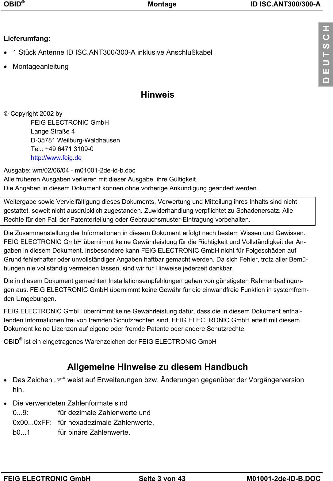
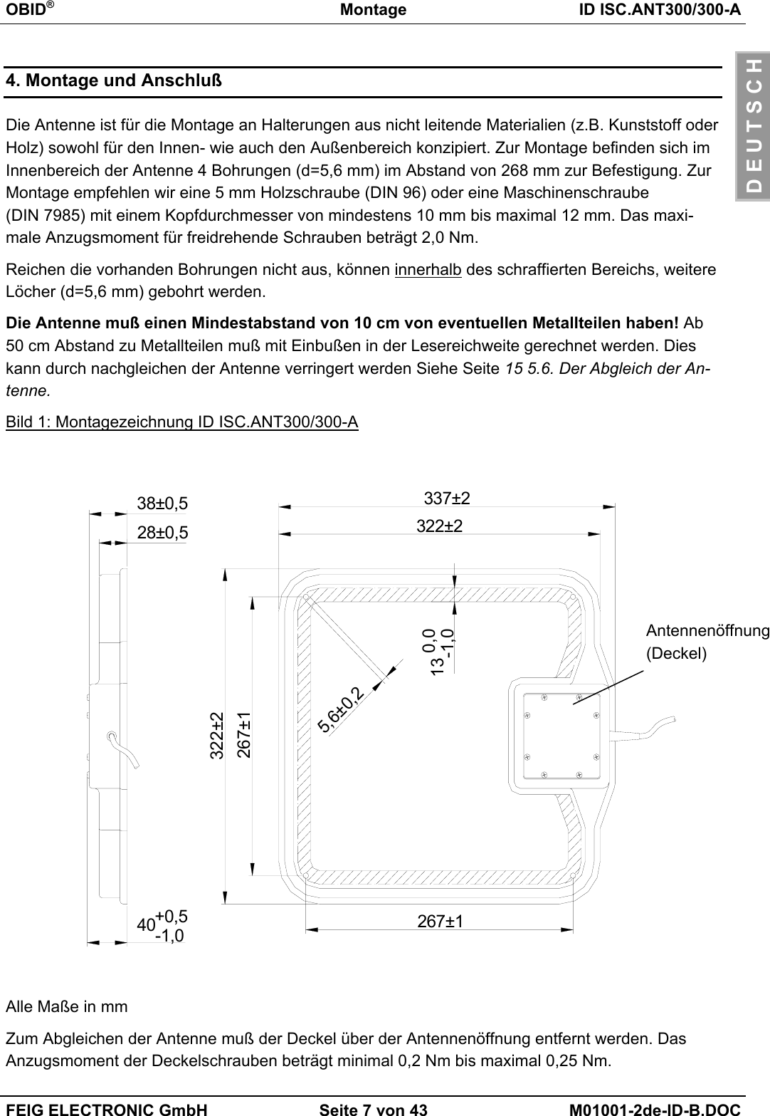
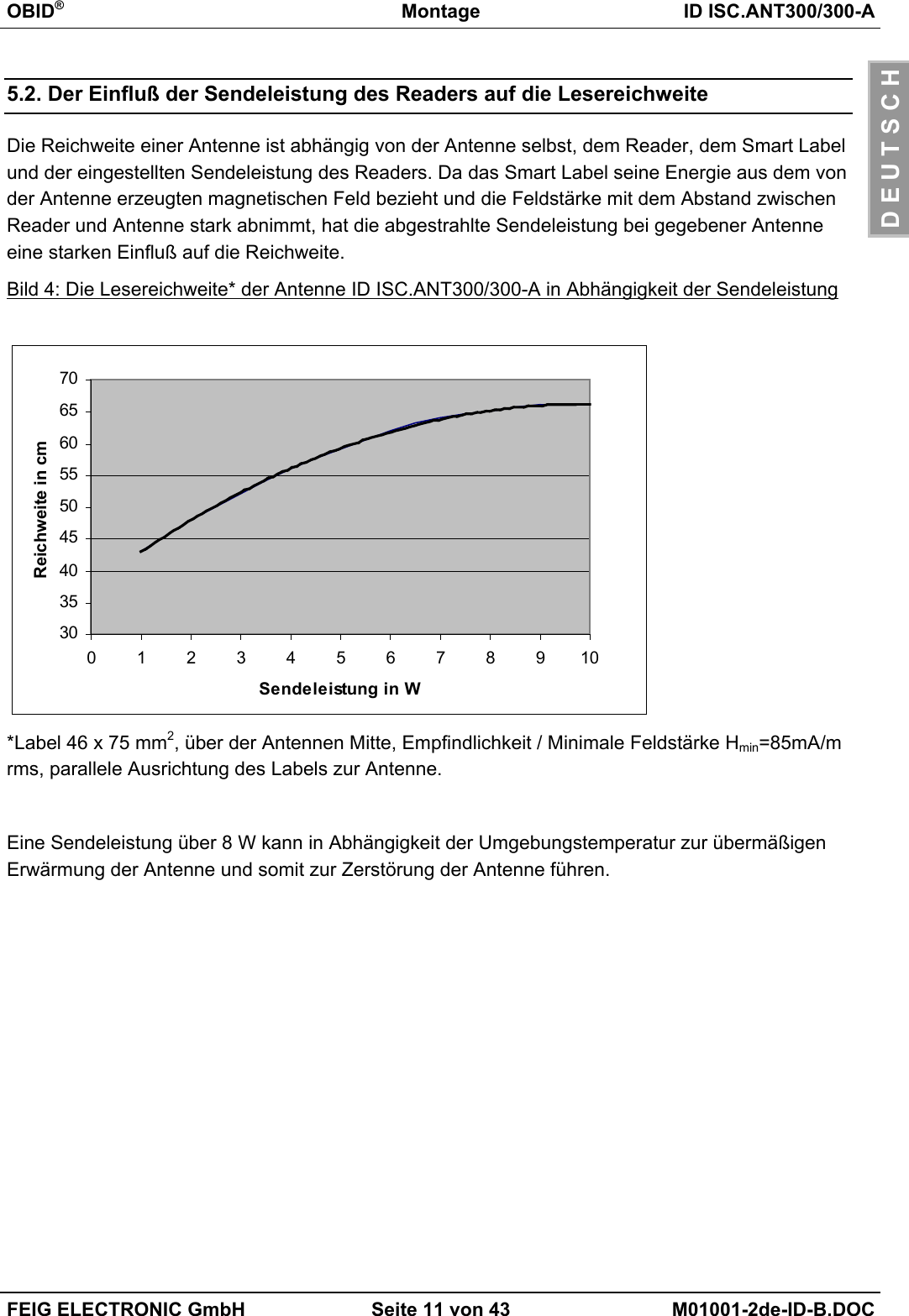
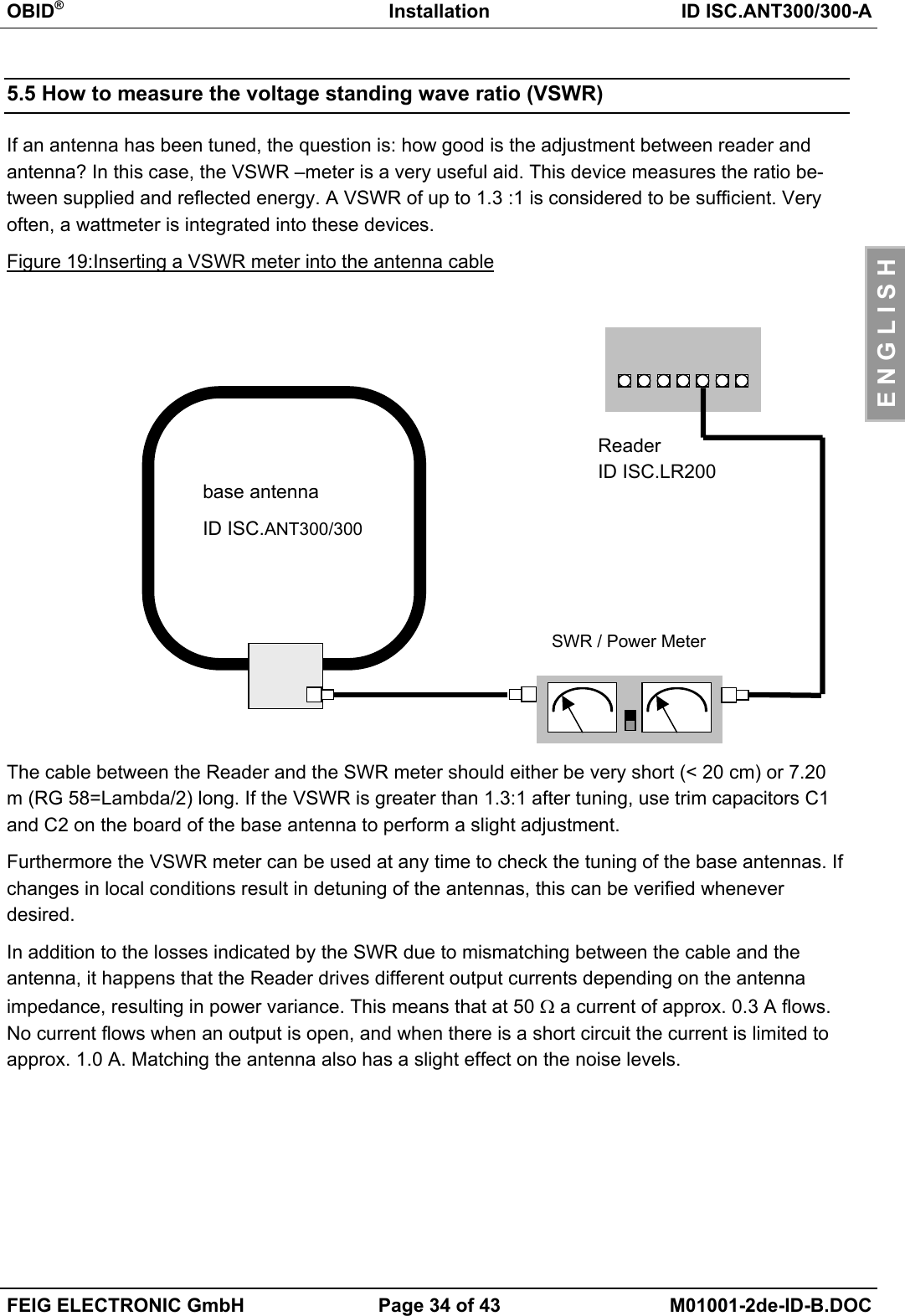
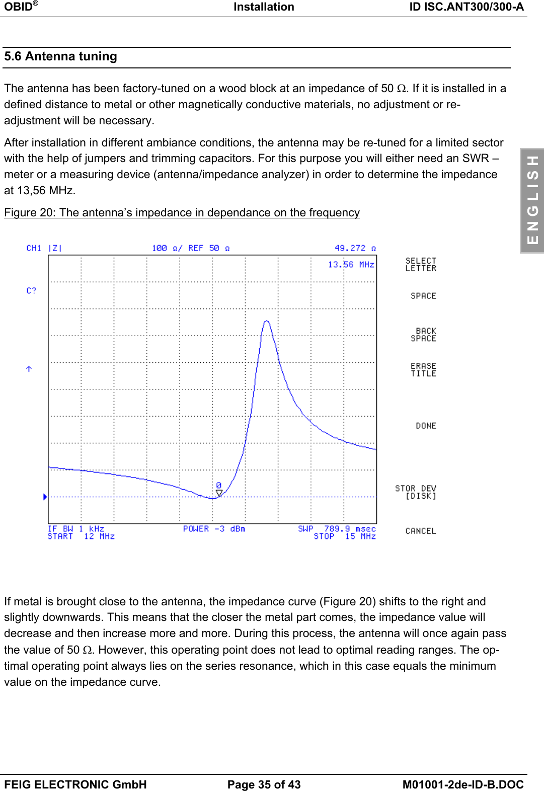
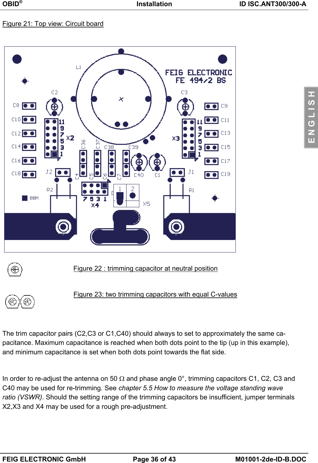
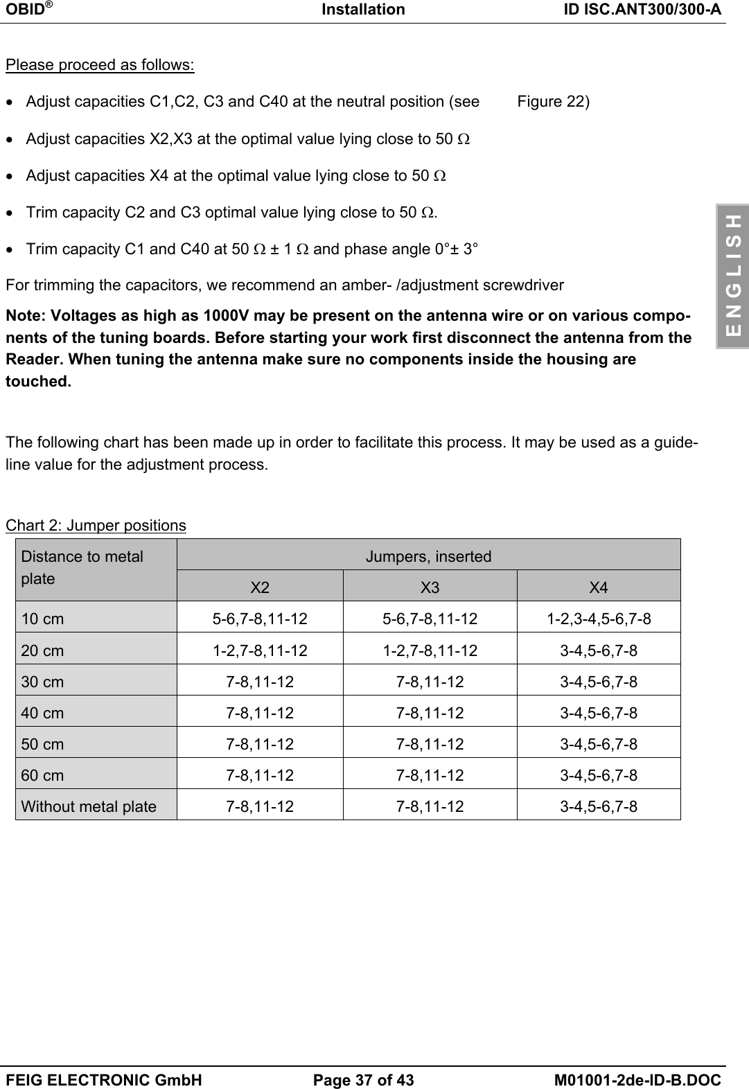
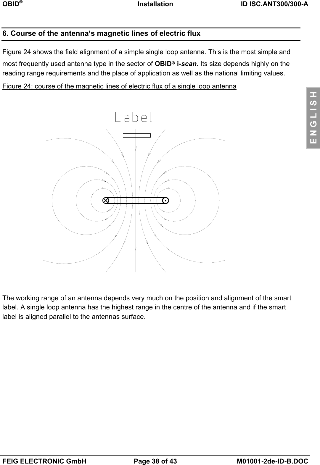
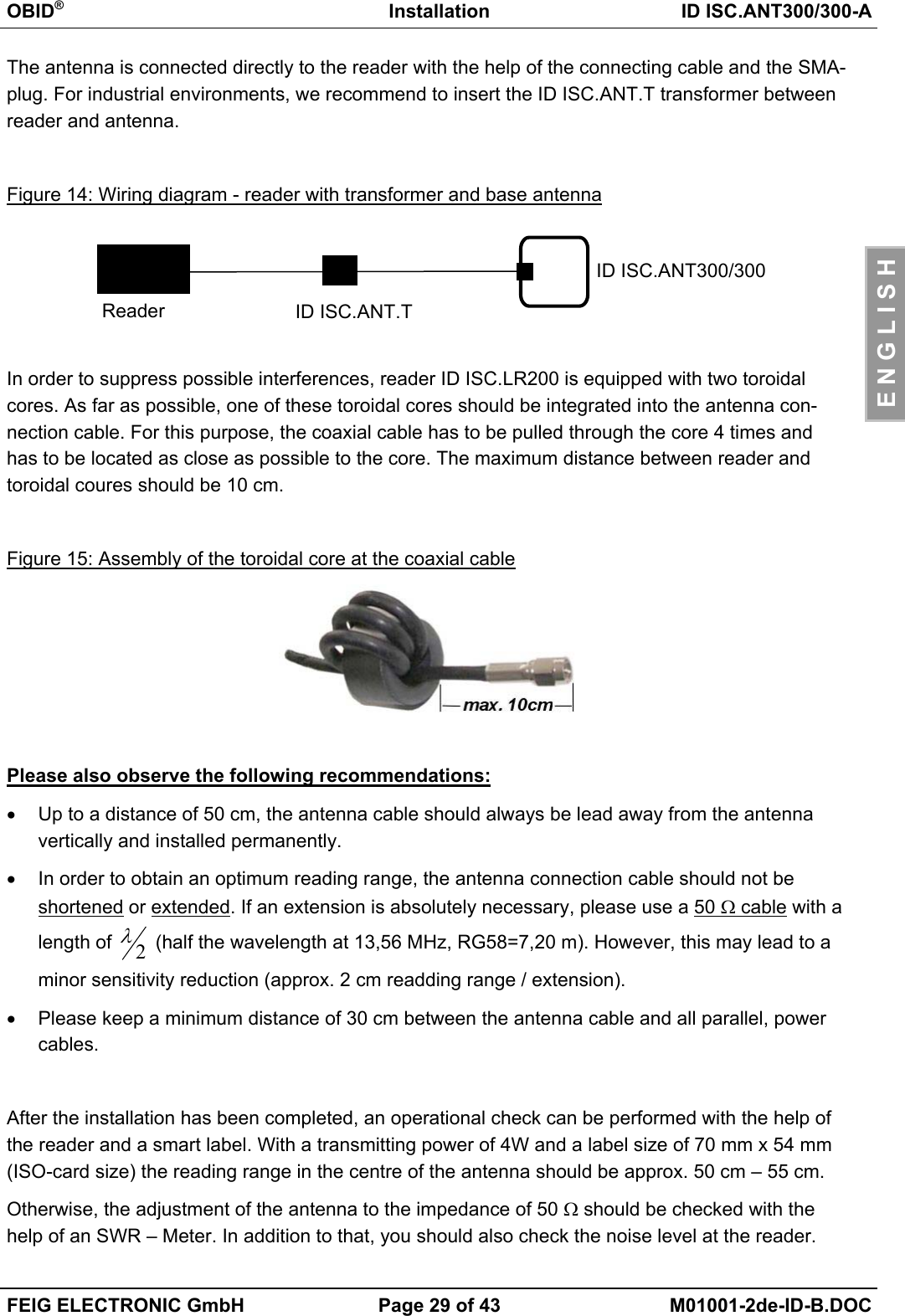
![OBID®Montage ID ISC.ANT300/300-AFEIG ELECTRONIC GmbH Seite 12 von 43 M01001-2de-ID-B.DOCD E U T S C H5.3. Der Einfluß von Metall auf die ReichweiteMetall und andere leitende Stoffe kann ein magnetisches Feld nicht durchdringen. Der Feldlinien-verlauf und die Induktivität der Antenne wird verändert und hat somit einen großen Einfluß auf dieReichweite. Weiterhin wird das Feld durch die Gegeninduktivität bzw. die Wirbelströme im Metallgeschwächt.Die Änderung der Induktivität kann mit Hilfe der Abgleichelektronik ausgeglichen werden. Bild 5zeigt den Einfluß einer Metallplatte auf die Antenne mit und ohne Nachgleich.Bild 5: Lesereichweite* in Abhängigkeit zum Abstand zu Metall Mit Nachgleich Ohne Nachgleich*Label 46 x 75 mm2, über der Antennen Mitte, Empfindlichkeit / Minimale Feldstärke Hmin=85mA/mrms, parallele Ausrichtung des Labels zur Antenne. Sendeleistung 4 W.Ist Metall in der Nähe der Antenne nicht zu vermeiden sollte folgendes beachtet werden:• Mindestabstand Metall zur Antenne 10 cm. Ab 30 cm ist mit starken Einbusen der Lesereich-weite zu rechnen. Ab 50 cm Abstand zum Metall ist nahezu kein Einfluß meßbar.• Die Metallteile dürfen keine geschlossenen Schleifen oder Stromkreise bilden. Diese sind ge-gebenenfalls an einer Stelle elektrisch zu trennen.• Die Metallteile in unmittelbarer Nähe der Antenne sind mit einer guten HF-Verbindung stern-förmig zu Erden.303540455055600 102030405060Abstand zur Metallplatte [cm]Reichweite [cm]](https://usermanual.wiki/Feig-Electronic/MR200.Users-Manual-Antenna-1/User-Guide-527652-Page-12.png)
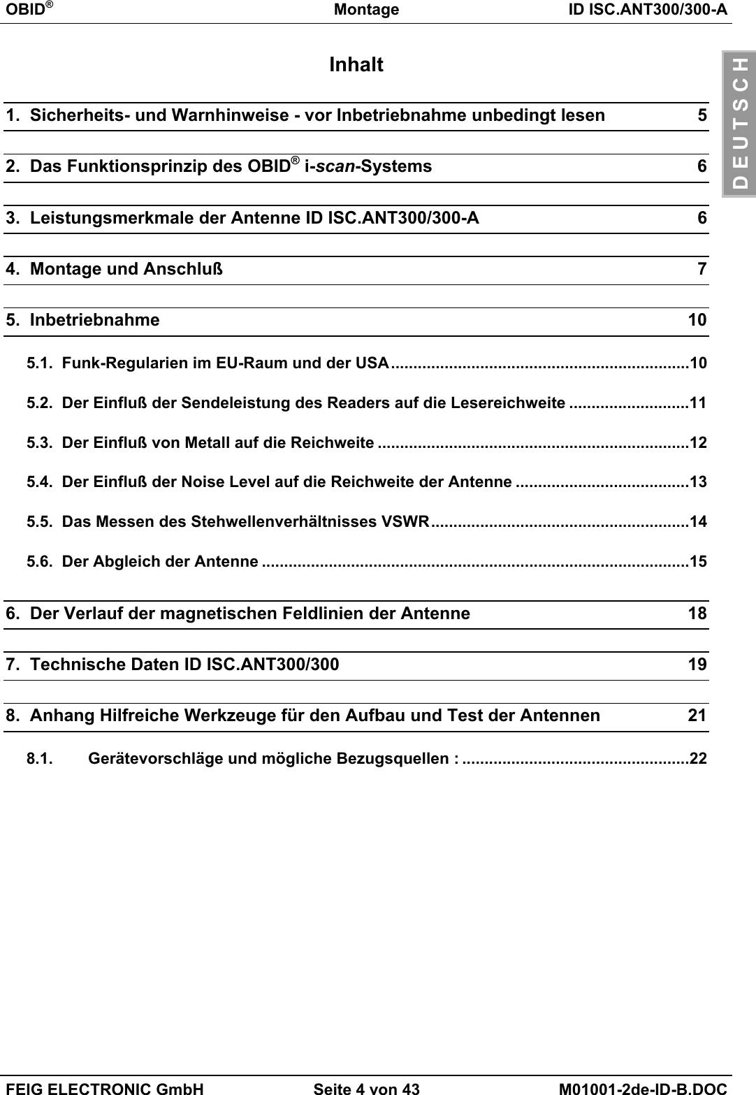
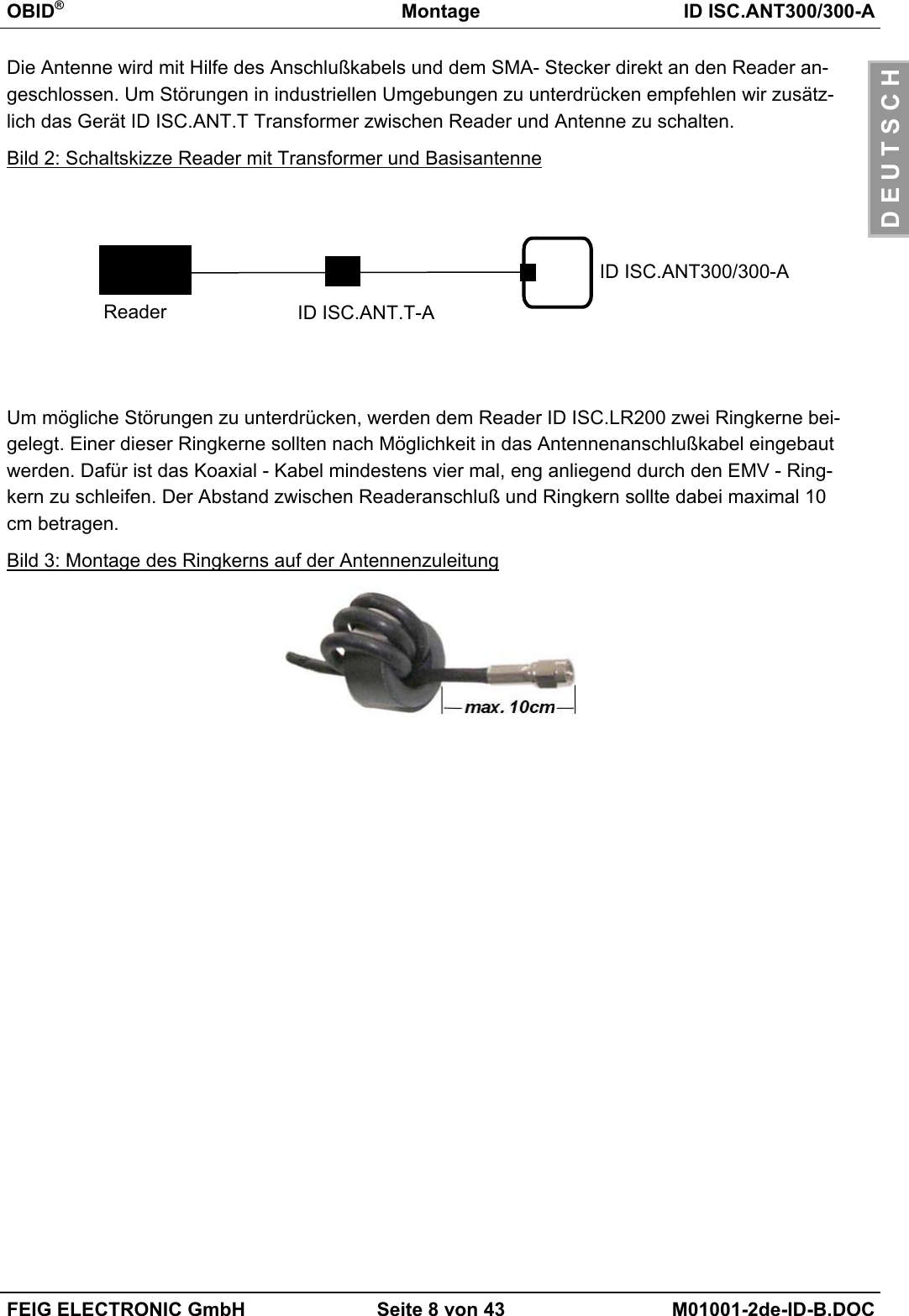
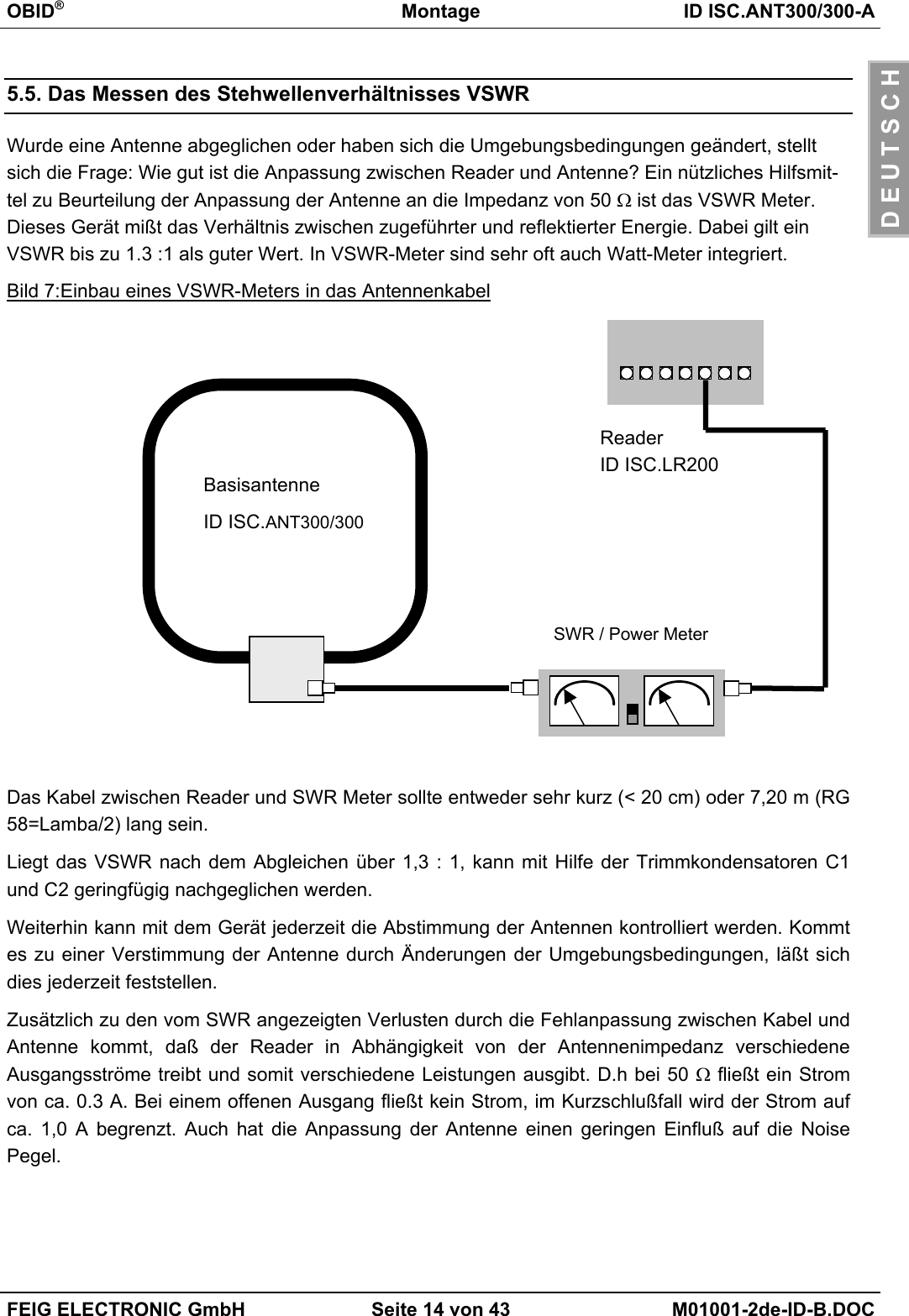
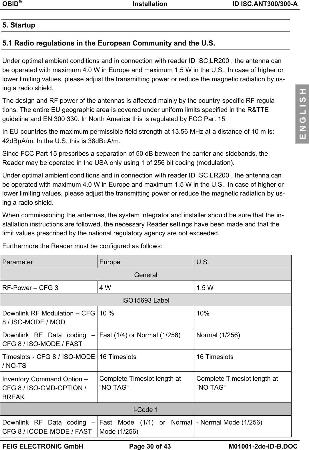
![OBID®Montage ID ISC.ANT300/300-AFEIG ELECTRONIC GmbH Seite 13 von 43 M01001-2de-ID-B.DOCD E U T S C H5.4. Der Einfluß der Noise Level auf die Reichweite der AntenneDamit das Smart Label vom Empfänger auch bei kleinen Signalpegeln zuverlässig gelesen werdenkann, müssen Störungen weitgehend vermieden werden. Die Amplitude der Störpegel läßt sich amReader ID ISC.LR200 an Hand der Noise Level (Rausch Pegel) abfragen. Dabei sind nicht dieabsoluten Meßwerte sondern die Differenz zwischen Umax und Umin ausschlaggebend.Im folgenden Bild wurde dies bei 4 W Sendeleistung simuliert und grafisch dargestellt.Bild 6: Lesereichweite* in Abhängigkeit der Noise Level*Label 46 x 75 mm2 über der Antennen Mitte, Empfindlichkeit / Minimale Feldstärke Hmin=85mA/mrms, parallele Ausrichtung des Labels zur Antenne. Sendeleistung 4 W.Die Differenz der Noise Level (Umax-Umin) sollte kleiner gleich 20 mV sein.Ursache für zu hohe Noise Level können sein:• Schlechte (HF-)Verbindungen zwischen Reader und Antenne.• Falsche Kabelführung zwischen Antenne und Reader• Eine schlecht abgestimmte Antenne• Störsignale von anderen elektronischen Geräten oder Sendern.• Störsignale auf der Energieversorgungsleitung des Readers• Störsignale von anderen Kabel in der Nähe der Kabel zum und vom Reader• Metall in der Nähe der Antenne2025303540455055600 100 200 300 400 500Noise Level Umax-UminReichweite [cm]](https://usermanual.wiki/Feig-Electronic/MR200.Users-Manual-Antenna-1/User-Guide-527652-Page-13.png)
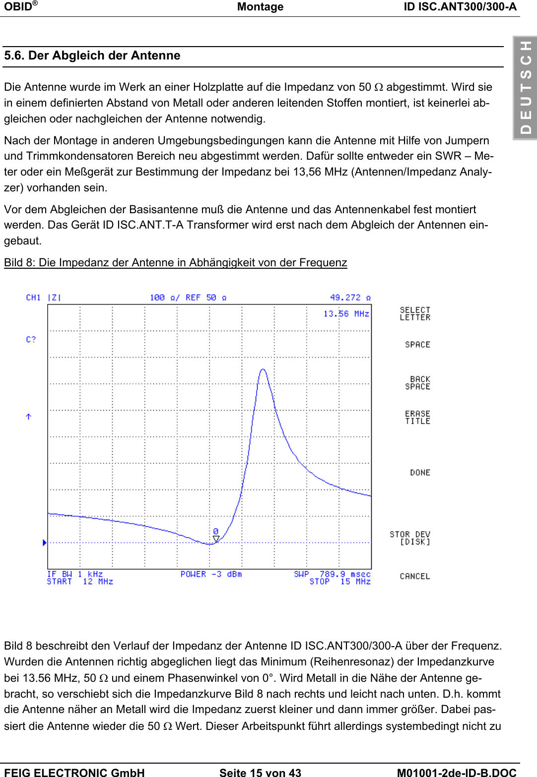
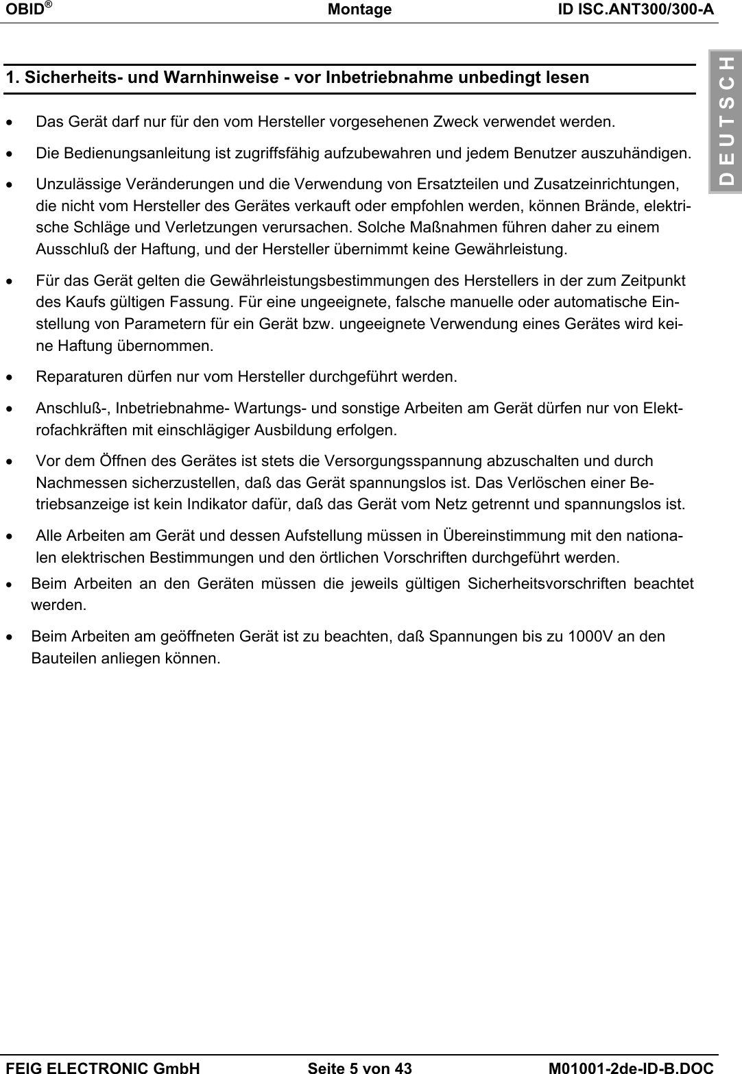
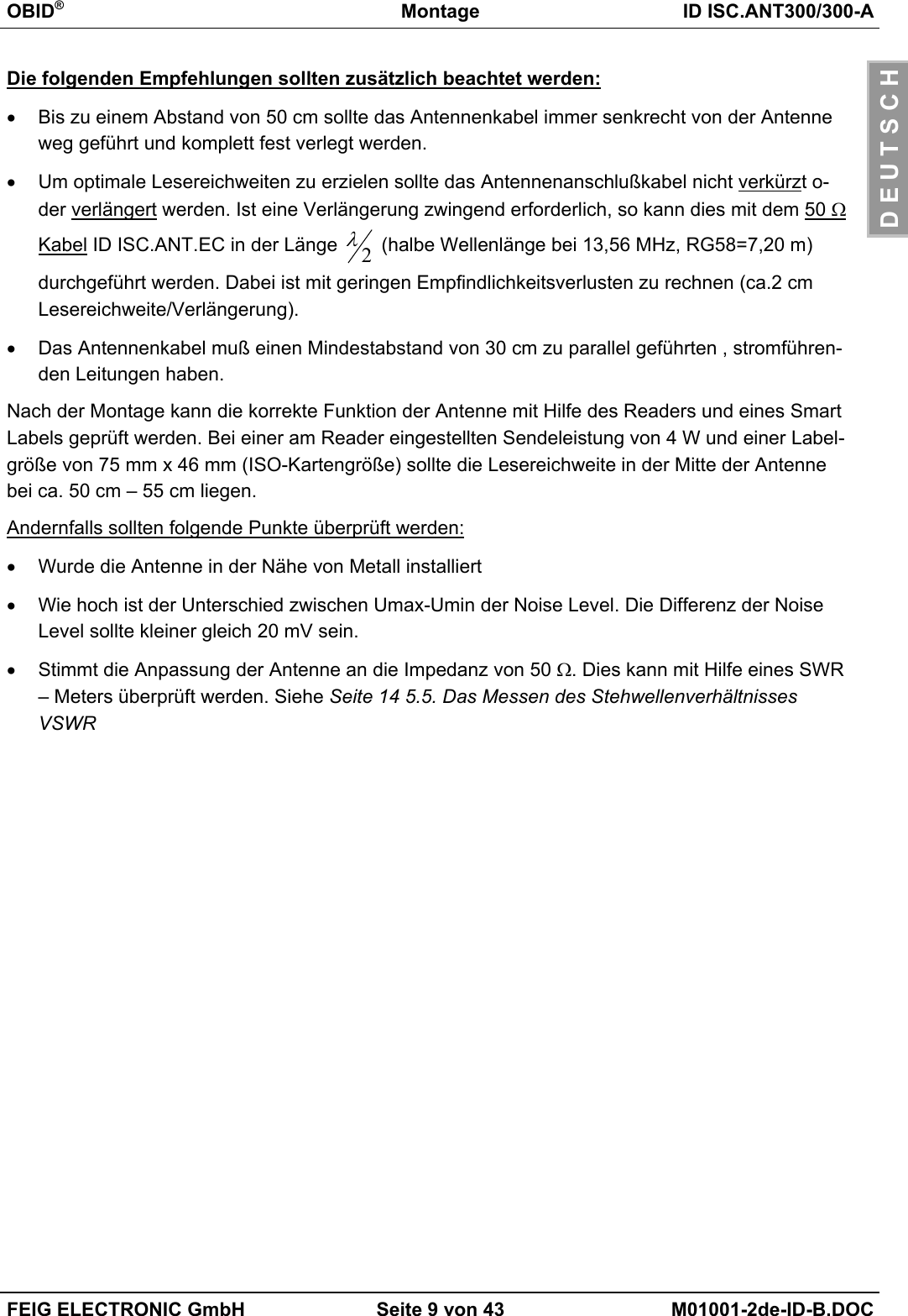
![OBID®Installation ID ISC.ANT300/300-AFEIG ELECTRONIC GmbH Page 31 of 43 M01001-2de-ID-B.DOCE N G L I S H5.2 The influence of the transmitting power on the reading rangeThe antenna’s working range is dependent on the antenna itself, the reader, the smart label andthe adjusted transmitting power of the reader. Due to the fact that the smart label gets its energyfrom the magnetic field produced by the antenna and that the field intensity decreases at higherdistances, the radiated transmitting power has strong influence on the range.Figure 16: reading range* in dependance on the transmitting power*Label 46 x 75 mm2, over the centre of the antenna, sensitivity / minimum operating fieldHmin=85mA/m rms, parallel orientation to the antenna,. transmitting power 4 W.A transmitting power of more than 8 W could, in dependance on the ambient temperature, heat upthe antenna and may even destroy it.303540455055606570012345678910transmitting power [W]reading range [cm]](https://usermanual.wiki/Feig-Electronic/MR200.Users-Manual-Antenna-1/User-Guide-527652-Page-31.png)
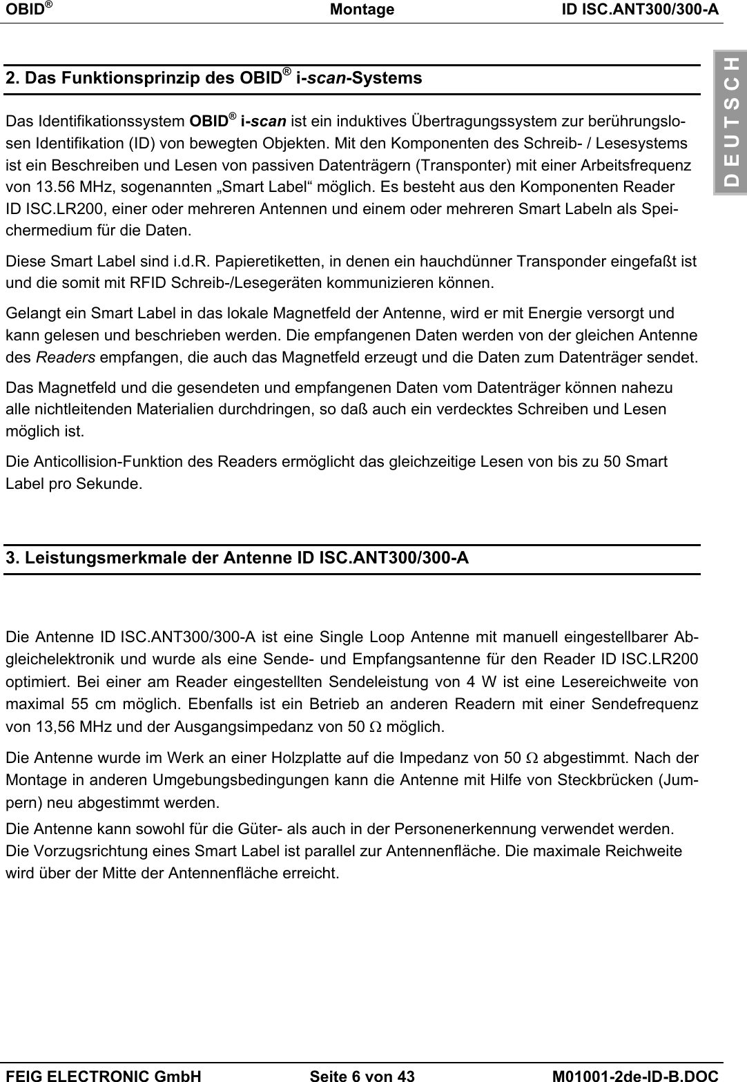
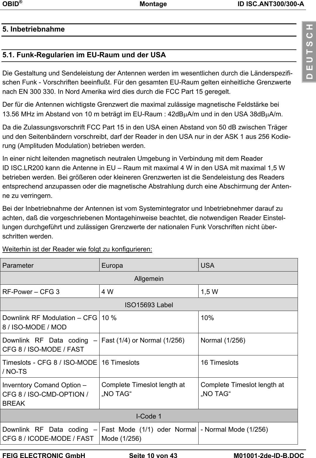
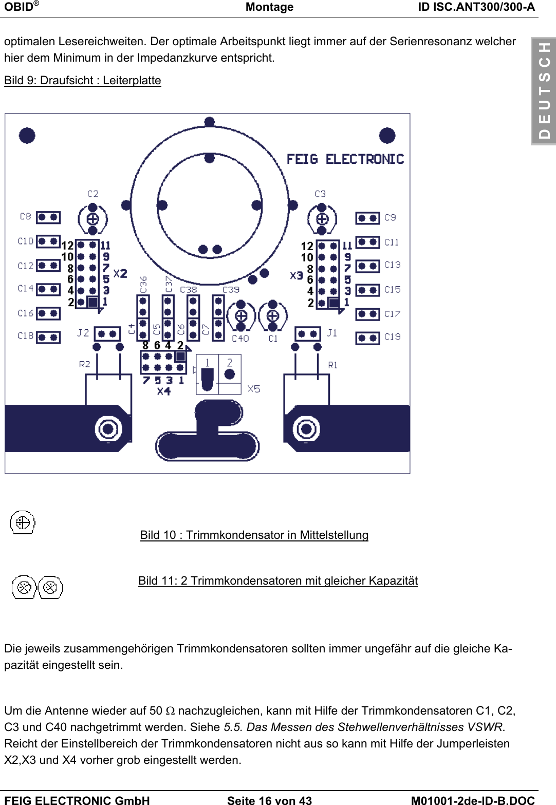
![OBID®Installation ID ISC.ANT300/300-AFEIG ELECTRONIC GmbH Page 32 of 43 M01001-2de-ID-B.DOCE N G L I S H5.3 The influence of metal on the reading rangeA magnetic field cannot penetrate metal or other magnetically conductive materials. The course ofthe lines of electric flux and the inductivity of the antenna is changed and has therefore a consider-able influence on the reading range. Furthermore, the filed is weakened by the mutual inductanceresponse the eddy current within the metal.The change of inductivity may often be compensated with the help of the tuning electronics. Figure17 illustrates the influence of a metal plate on the antenna with (upper line) and without rebalanc-ing.Figure 17: reading range* in dependance on the distance to metal*Label 46 x 75 mm2, over the centre of the antenna, sensitivity / minimum operating fieldHmin=85mA/m rms, parallel orientation to the antenna,. transmitting power 4 W.If metal parts cannot be avoided close to the antenna, please observe the following:• The minimum distance between metal and antenna is 10 cm. A distance of 30 cm will lead to aconsiderable reduction in the reading range. At a distance of 50 cm to metal parts, there will bealmost no influence to be measured.• Metal parts must not form closed loops or electric circuits. These have to be electrically sepa-rated at one point.• Metal parts in close vicinity to the antenna have to be grounded in star configuration with agood HF-connection.303540455055600 102030405060distance to metal [cm]reading range [cm]](https://usermanual.wiki/Feig-Electronic/MR200.Users-Manual-Antenna-1/User-Guide-527652-Page-32.png)
![OBID®Installation ID ISC.ANT300/300-AFEIG ELECTRONIC GmbH Page 33 of 43 M01001-2de-ID-B.DOCE N G L I S H5.4 The influence of the noise level on the antenna’s working rangeInterferences have to be largely avoided, so that the smart label may be read by the receiver evenat low signal levels. The amplitude of the interference levels can be found out at readerID ISC.LR200 with the help of the noise levels. Critical are not the absolute measured values, butrather the difference between Umax-Umin.This has been simulated at 4W and represented graphically in the following figure.Figure 18: reading range* in dependance on the noise levels*Label 46 x 75 mm2, over the centre of the antenna, sensitivity / minimum operating fieldHmin=85mA/m rms, parallel orientation to the antenna,. transmitting power 4 W.The difference of the noise levels (Umax - Umin) should be less than 20 mV.Possible reasons for excessive noise levels:• Bad (HF-)connections between reader and antenna.• Improper cable layout between antenna and reader• Badly tuned antenna• Interfering signals of other electronic appliances or transmitting stations.• Interfering signals on the reader’s power supply line.• Interfering signals coming from other cables close to the cables leading to and away from thereader.• Metal parts close to the antenna2025303540455055600 100 200 300 400 500Noise Level Umax-Uminreading range [cm]](https://usermanual.wiki/Feig-Electronic/MR200.Users-Manual-Antenna-1/User-Guide-527652-Page-33.png)