Feig Electronic MR200 Inductive Reader User Manual Antenna 2
Feig Electronic GmbH Inductive Reader Users Manual Antenna 2
UserManual.wiki
>
Feig Electronic
>
MR200 User Manual
>
Users Manual Antenna 2
Contents
1.
Users Manual
2.
Users Manual Antenna 1
3.
Users Manual Antenna 2
Users Manual Antenna 2
Navigation menu
Upload a User Manual
Namespaces
Wiki Guide
HTML
PDF
Info
Views
User Manual
Discussion / Help
Navigation
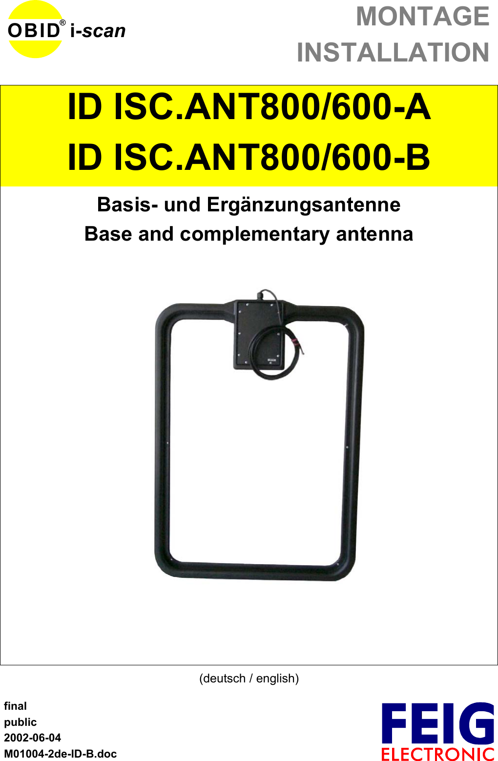
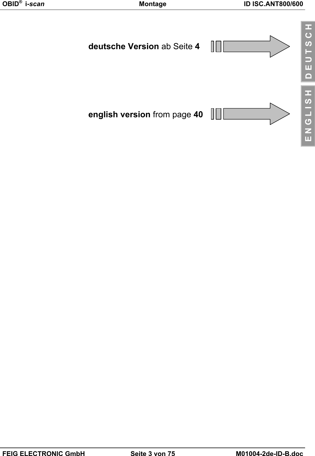
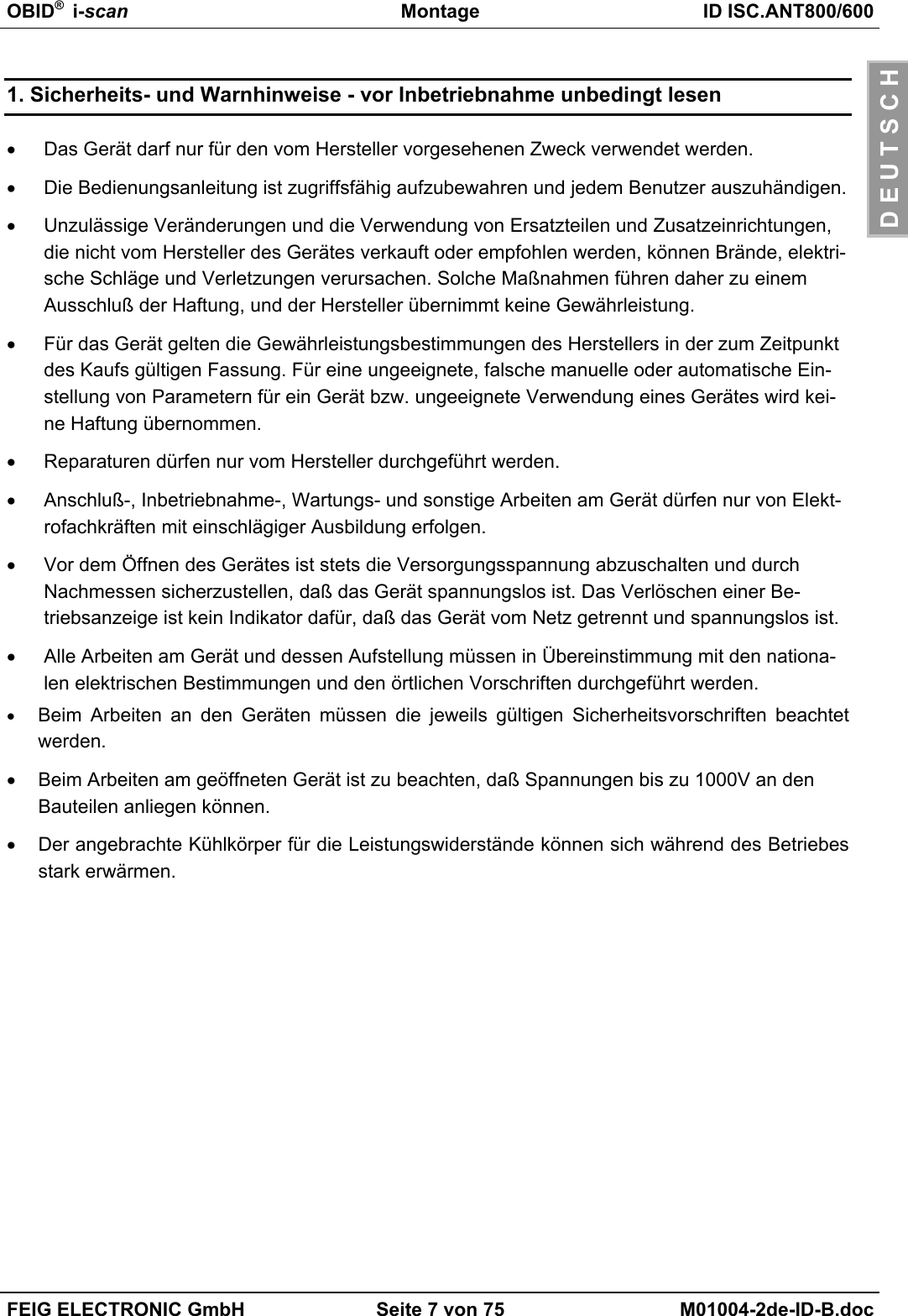
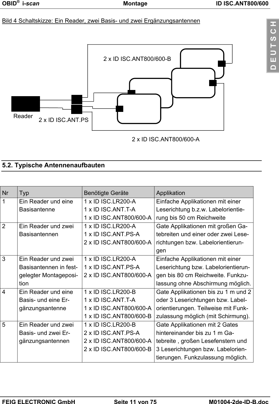
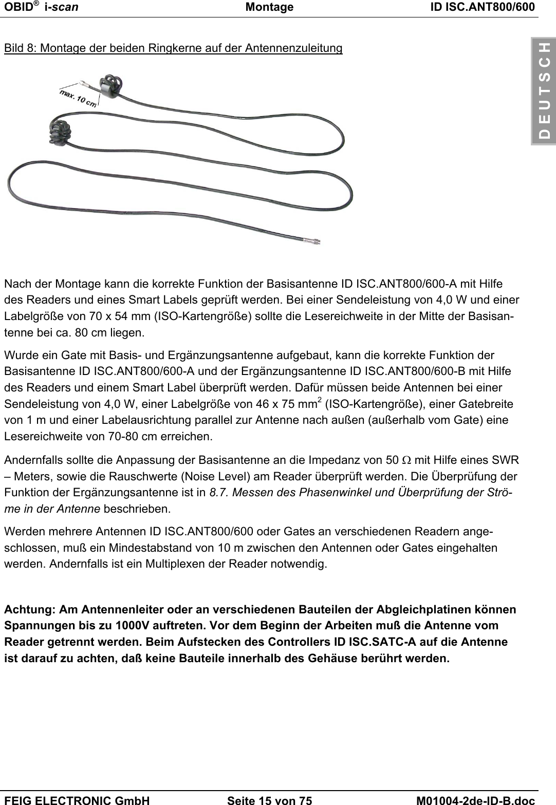
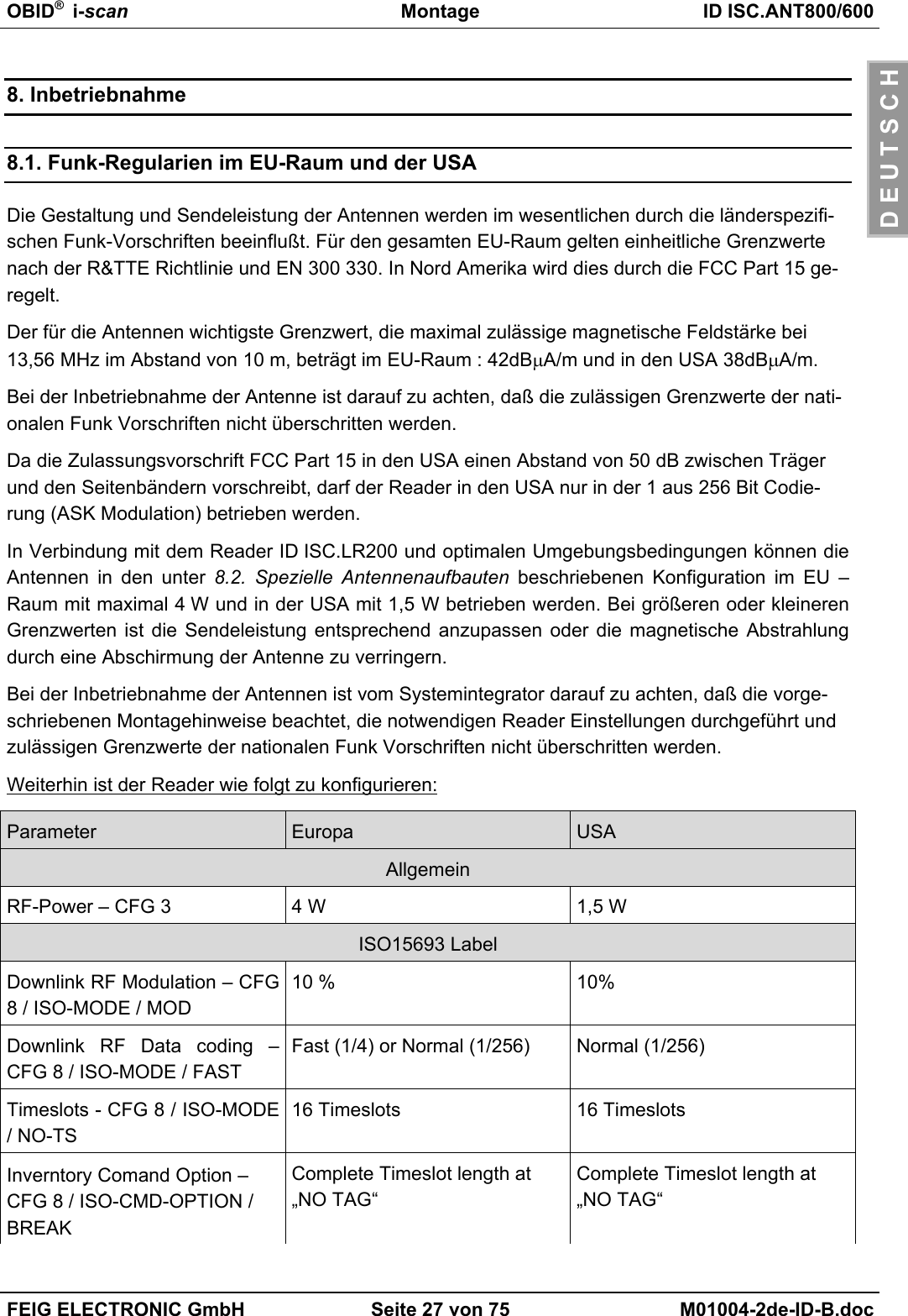
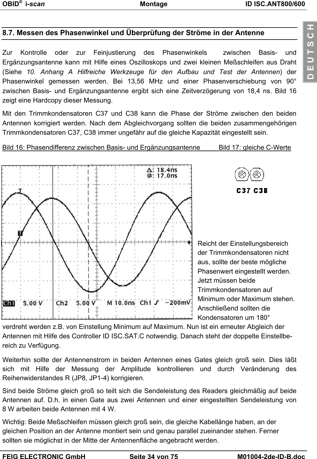
![OBID® i-scan Montage ID ISC.ANT800/600FEIG ELECTRONIC GmbH Seite 16 von 75 M01004-2de-ID-B.docD E U T S C H6.1. Hinweise zur Kabelführung der AntennenzuleitungBei der Kabelführung bzw. beim Aufbau von Einzelantennen oder Antennen Gates ist auf folgen-des zu achten:• Das Antennenkabel ist immer vor dem Abgleichen fest zu verlegen. Bei späteren Änderungensollten mit den Oszilloskope die Phase und Amplitude der Ströme kontrolliert werden.• Bis zu einem Abstand von 50 cm sollte das Antennenkabel immer senkrecht von der Antenneweg geführt werden.• Muß das Antennenkabel näher an der Antenne entlang verlegt werden, so sind mindestens20 cm Abstand einzuhalten.• Ein Verlegen des Antennenkabel durch die Antenne ist immer ungünstig. Falls sich dies nichtVermeiden läßt darf das Antennenkabel nur im Winkel von 90 Grad zum Abgleich, zum gege-nüberliegenden Antennenrohr in der Mitte der Antenne verlegt werden.• Um optimale Lesereichweiten zu erzielen sollte das Antennenanschlußkabel nicht verkürzt oderverlängert werden. Ist eine Verlängerung zwingend erforderlich, so kann dies mit einem 50 ΩKabel in der Länge 2λ (halbe Wellenlänge bei 13,56 MHz, RG58=7,20 m) durchgeführt wer-den. Dabei ist mit geringen Empfindlichkeitsverlusten zu rechnen.• Das Antennenkabel muß einen Abstand von wenigstens 30 cm zu parallel geführten stromfüh-renden Leitungen haben.Bild 9: Lesereichweite* in Abhänigkeit der Antennenzuleitung in 2λSchritten*Label 46 x 75 mm2 über der Antennen Mitte, Empfindlichkeit / Minimale Feldstärke Hmin=85mA/mrms, parallele Ausrichtung des Labels zur Antenne. Sendeleistung 4 W7374757677787980810 3,62 7,24 10,86 14,48 18,1 21,72 25,34 28,96Länge der AntennenzuleitungReichweite [cm]](https://usermanual.wiki/Feig-Electronic/MR200.Users-Manual-Antenna-2/User-Guide-527653-Page-16.png)
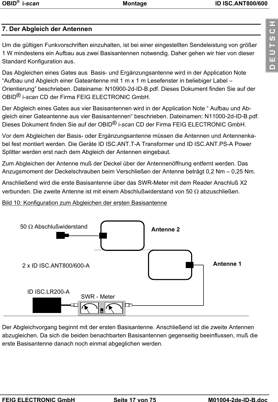
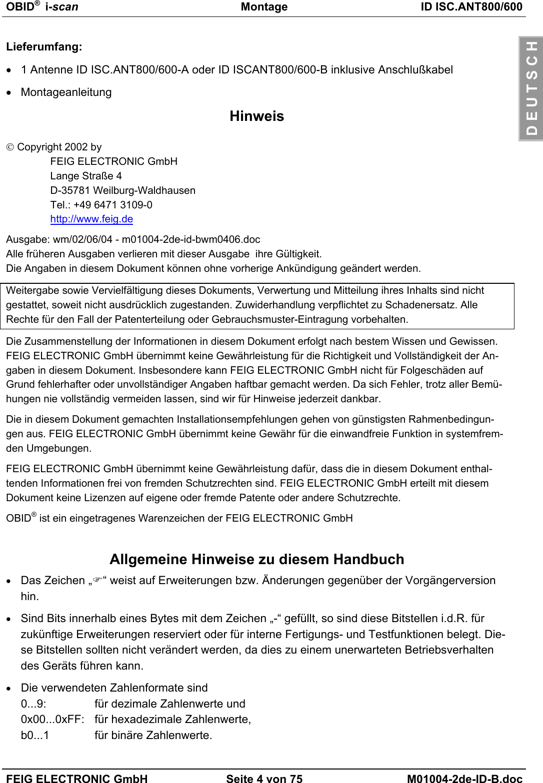
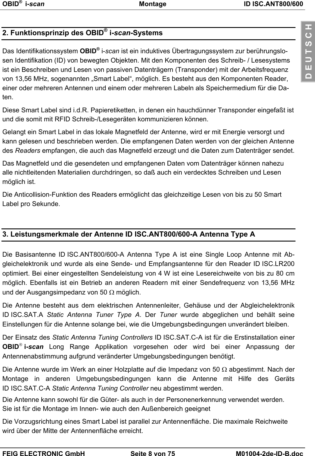
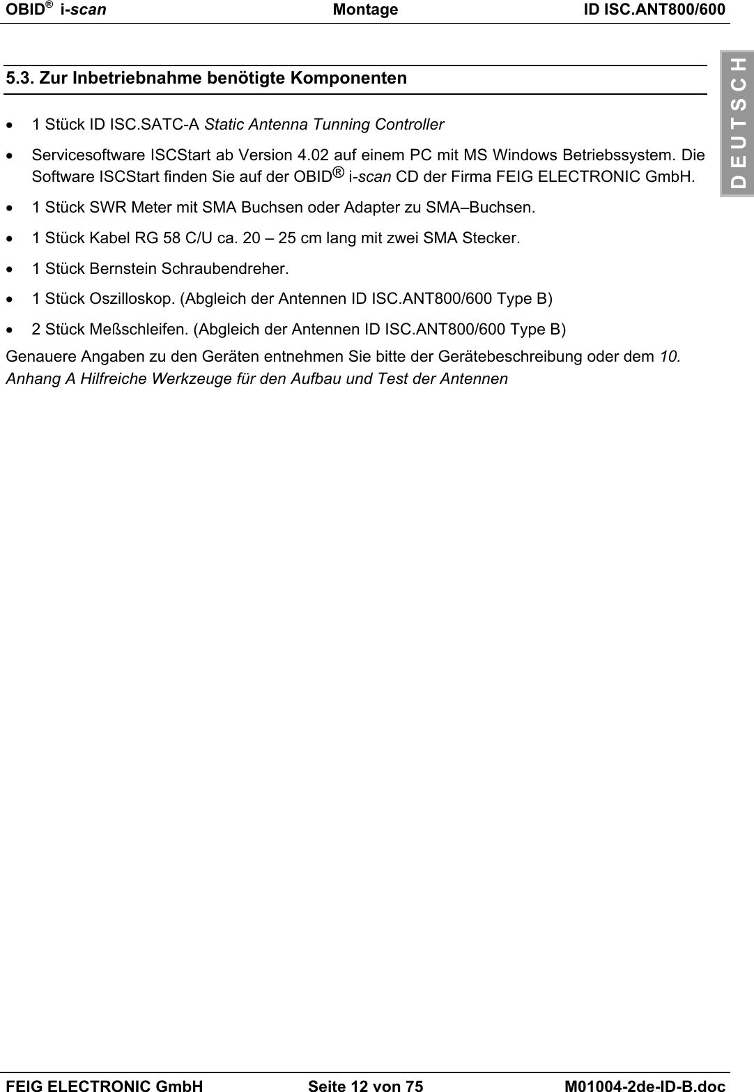
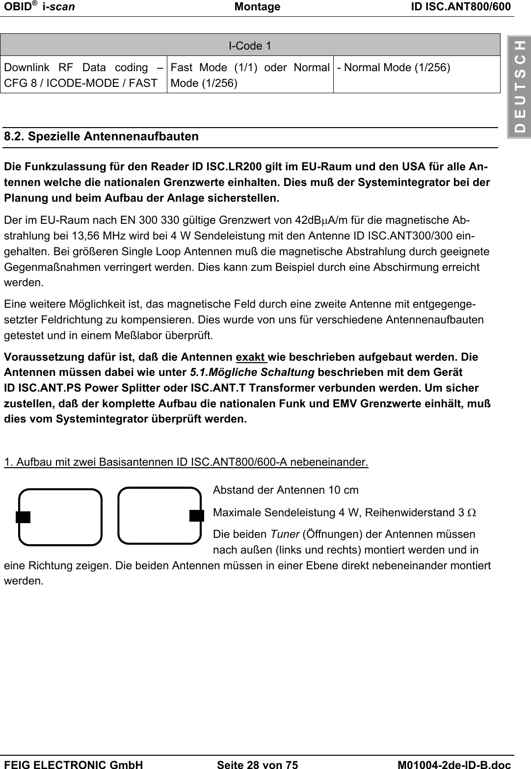
![OBID® i-scan Montage ID ISC.ANT800/600FEIG ELECTRONIC GmbH Seite 18 von 75 M01004-2de-ID-B.docD E U T S C H7.1. VorbereitungenStep Vorgang Hinweis1Verbinden Sie den ReaderID ISC.LR200 über die Schnitt-stelle RS232 oder RS485 mitdem PCSiehe Installation Manual ID ISC.LR2002Installieren Sie die Demo Soft-ware ISCStartAuf der OBID® i-scan CD3Starten Sie das ProgrammISCStart4Öffnen Sie die COM-Port Ein-stellungen5Überprüfen Sie die COM-PortEinstellungen und bestätigen Siemit dem OK-Button6Öffnen Sie nun das Menü File –New – Reader7Wählen Sie ID ISCLR und bes-tätigen Sie mit OK8Wählen Sie COM: x [Baud38400......]9Button Commands auswählen](https://usermanual.wiki/Feig-Electronic/MR200.Users-Manual-Antenna-2/User-Guide-527653-Page-18.png)
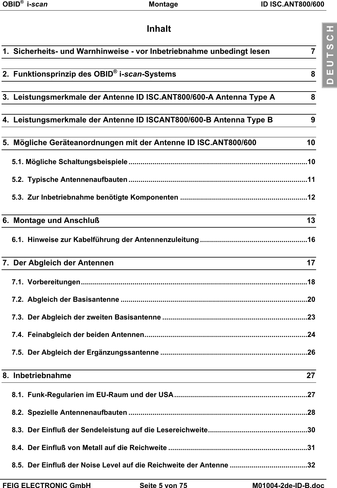
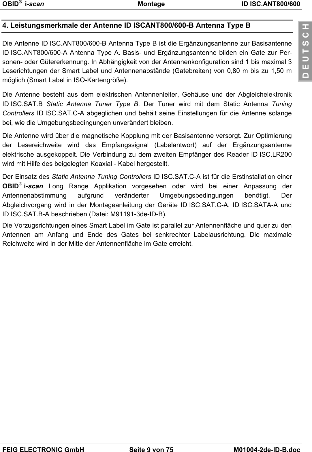
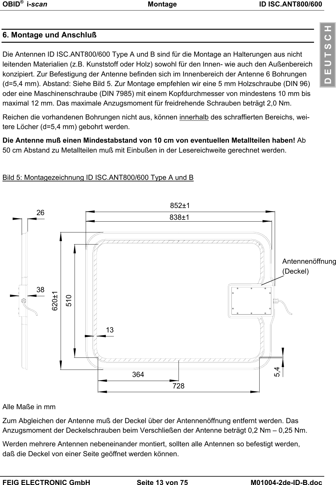
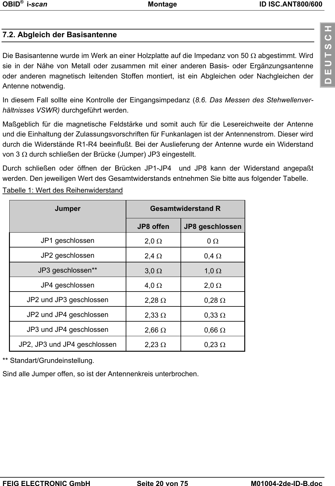
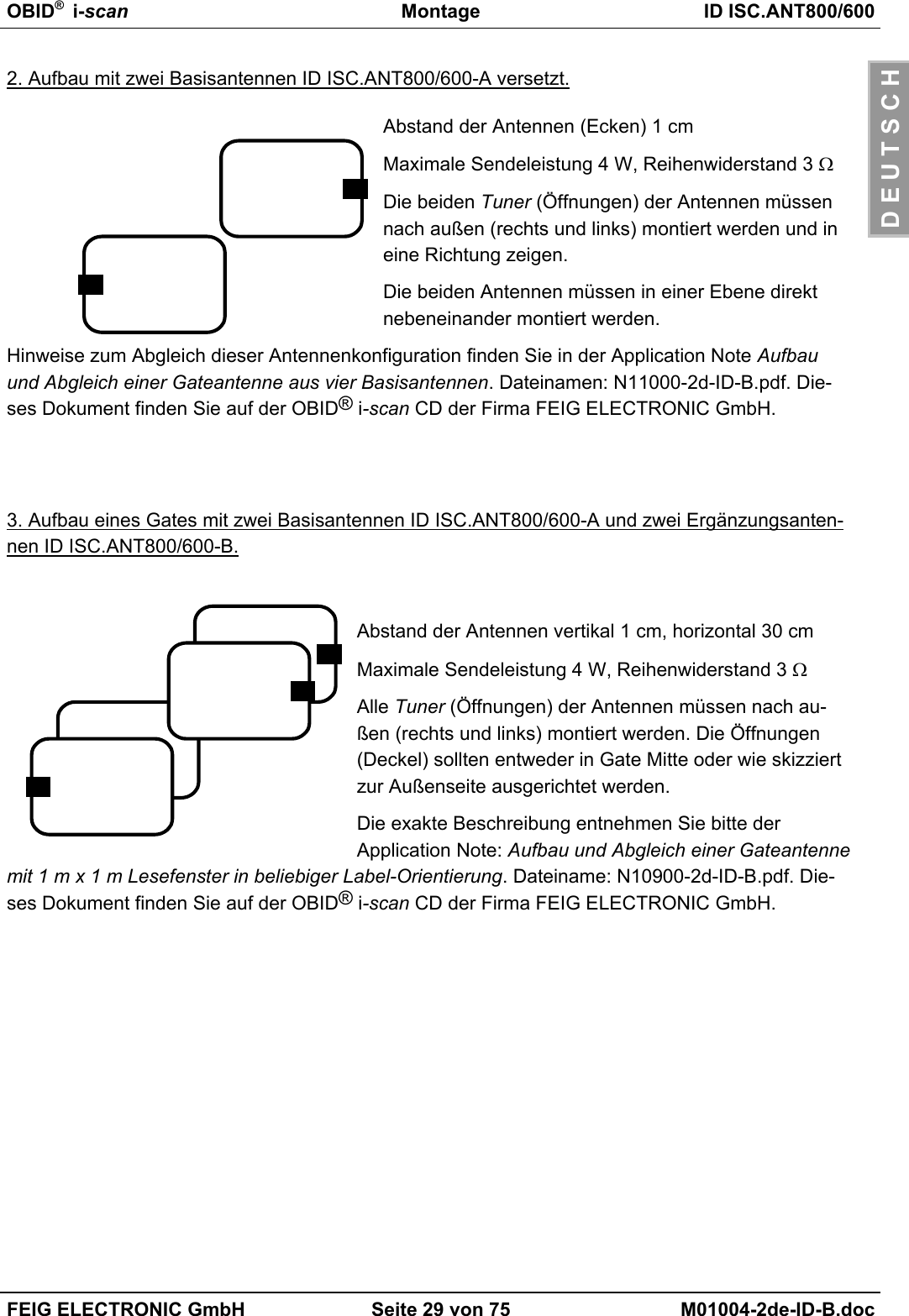
![OBID® i-scan Montage ID ISC.ANT800/600FEIG ELECTRONIC GmbH Seite 19 von 75 M01004-2de-ID-B.docD E U T S C H10 Befehl Baudrate Detetion[0x52] wählen11 Button Send auswählen12 Das Programm testet alle mögli-chen Baudraten. Es stoppt so-bald die am Reader eingestellteBaudrate erkannt wurde (Stan-dard 38400 / 8E1) mit OK.13 Button Configuration auswählen14 Zeile ID ISCLR Configurationwählen.15 Ziel – Speicher EEPROM aus-wählen.16 Mit Button Reset [0x83] ist derReader auf die Standard Konfi-guration einzustellen.17 Mit dem Button Read wird dieReader Konfiguration in den PCbzw. das Programm ISCStartgeladen.](https://usermanual.wiki/Feig-Electronic/MR200.Users-Manual-Antenna-2/User-Guide-527653-Page-19.png)
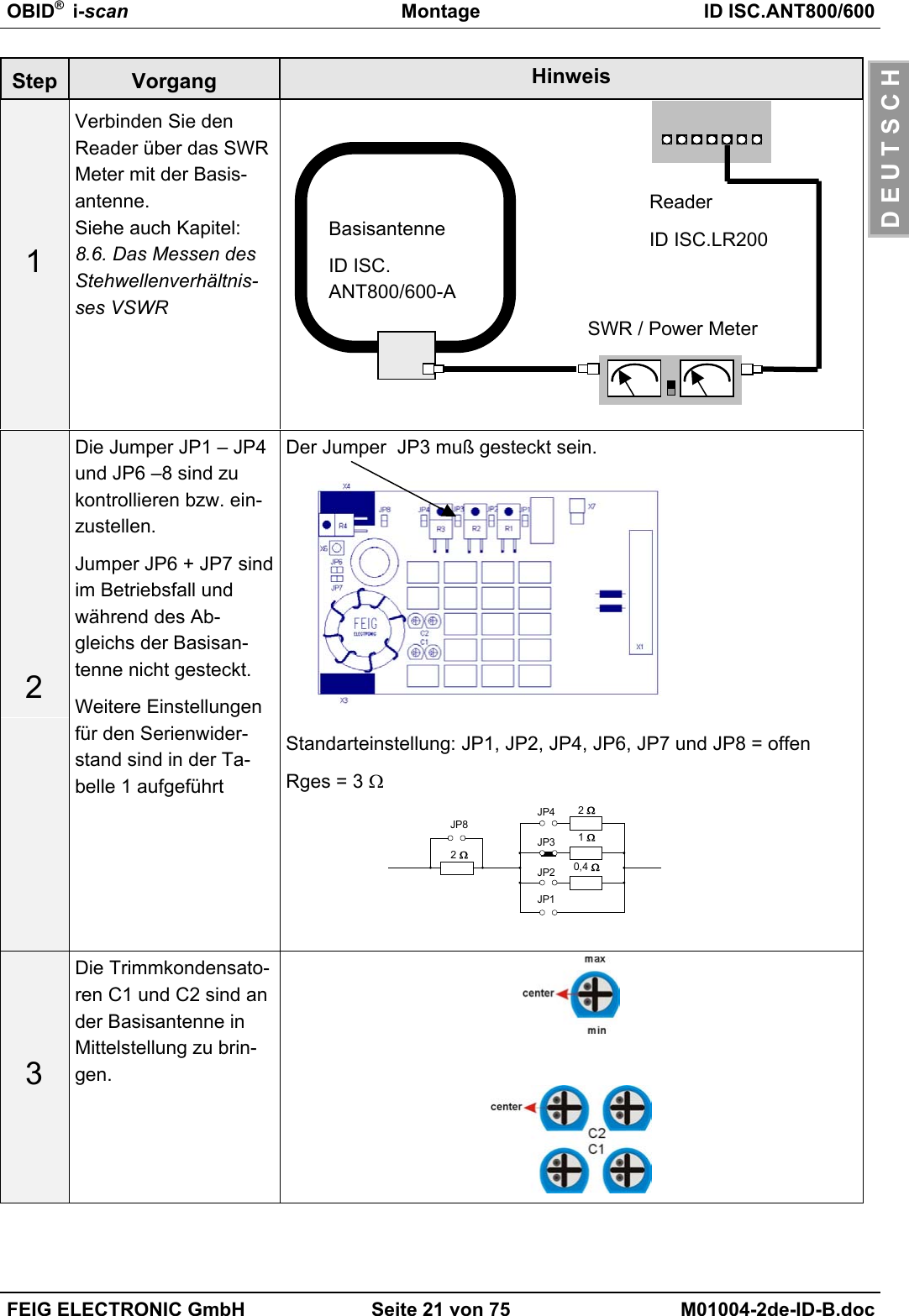
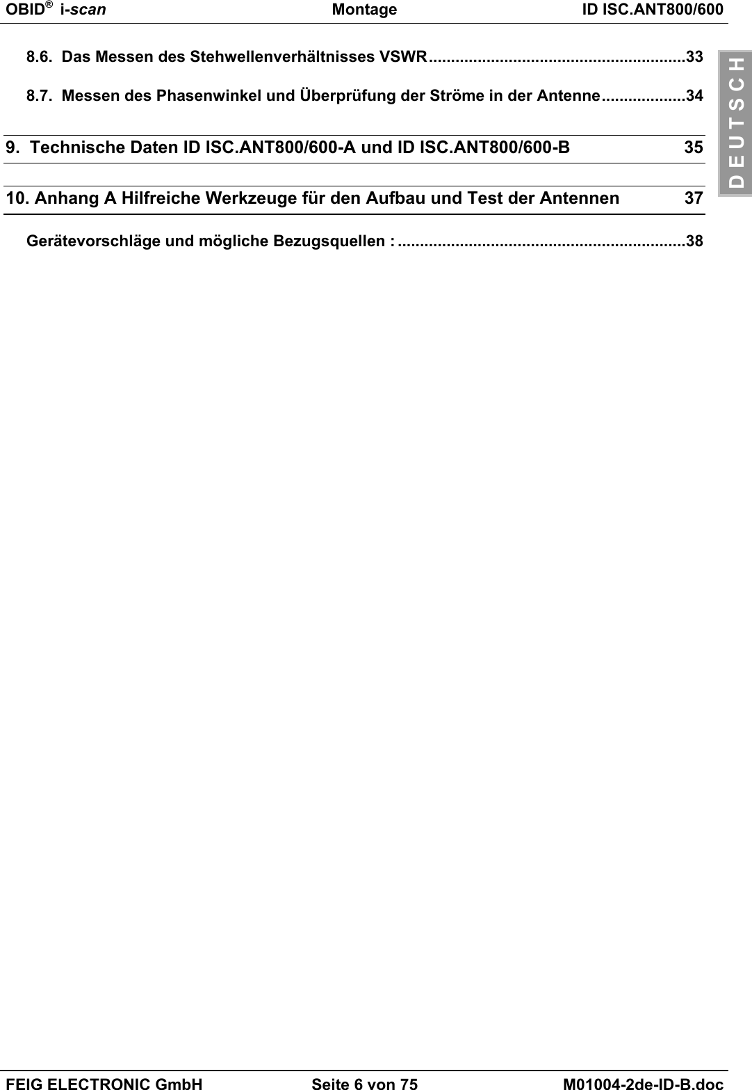
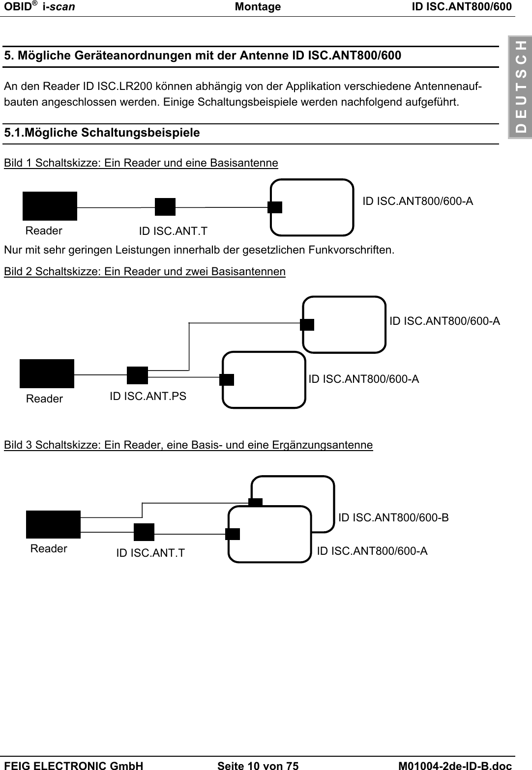
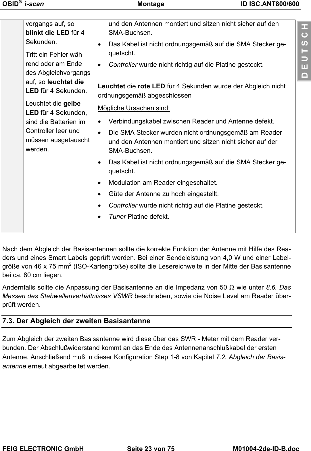
![OBID® i-scan Montage ID ISC.ANT800/600FEIG ELECTRONIC GmbH Seite 22 von 75 M01004-2de-ID-B.docD E U T S C H4Button Commandsauswählen5Befehl [0x6F] BaseAntenna Tunningausführen damit derReader in den Ab-gleichmodus geschal-tet wird.6Stecken Sie jetzt denStatic Antenna TuningControllerID ISC.SAT.C-A anden Antennentuner derBasisantenne und drü-cken Sie die Taste-„Start“ am Controller.Der Abgleichvorgangdauert einige Sekun-den und sollte durchein 4 Sekunden langesLeuchten der grünenLED abgeschlossenwerden..Abgleichmodus: Wird aktiviert durch längeres Drücken derStart Taste (> 2 Sekunden)Kontrollmodus: Wird aktiviert durch kurzes Drücken derStart Taste (< 2 Sekunden).7Danach schaltet sichder Controller automa-tisch ab und kann wie-der abgezogen wer-den.Nun kann mit dem Abgleich der Ergänzungsantenne begon-nen werden.8Wird der Abgleich nichtordnungsgemäß abge-schlossen, so wird diesdurch die rote LEDangezeigt.Tritt ein Fehler amAnfang des Abgleich-Blinkt die rote LED für 4 Sekunden so liegt keine RF-Leistung ander Antenne.Mögliche Ursachen sind:• Reader oder RF-Leistung ausgeschaltet• Verbindungskabel zwischen Reader und Antenne defekt.• Die SMA Stecker wurden nicht ordnungsgemäß am ReaderWichtig:Den Controller nicht vor demerlöschen der grünen LED ab-ziehen!](https://usermanual.wiki/Feig-Electronic/MR200.Users-Manual-Antenna-2/User-Guide-527653-Page-22.png)
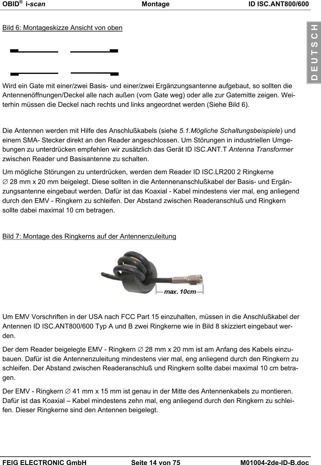
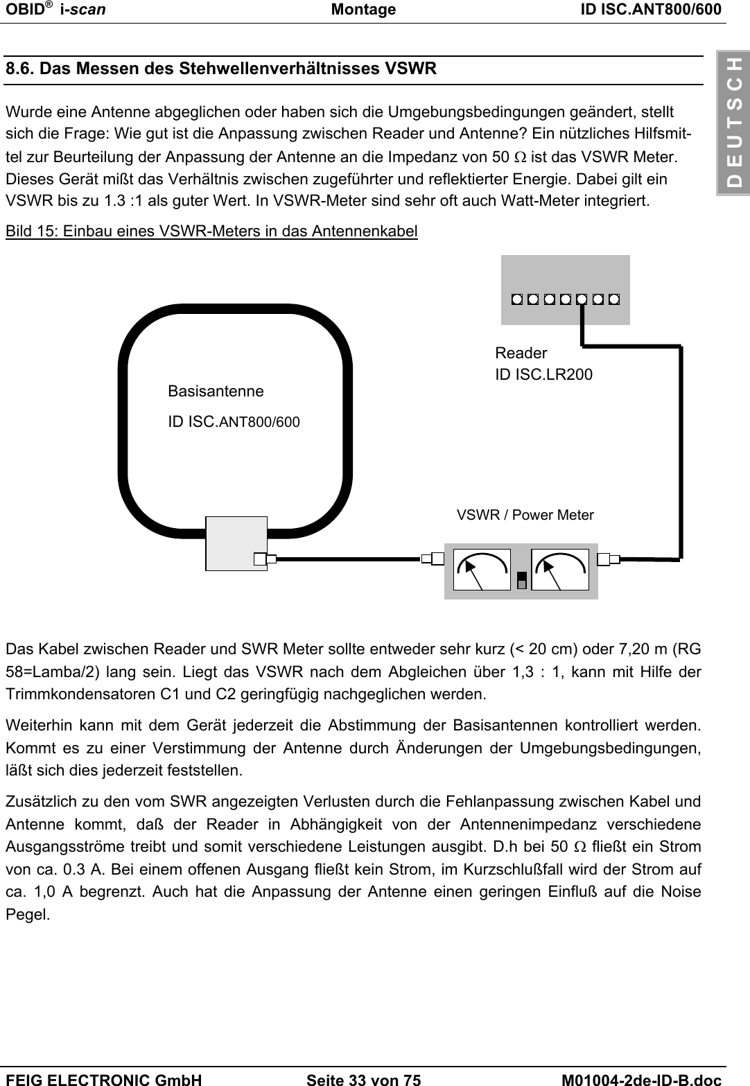
![OBID® i-scan Montage ID ISC.ANT800/600FEIG ELECTRONIC GmbH Seite 30 von 75 M01004-2de-ID-B.docD E U T S C H8.3. Der Einfluß der Sendeleistung auf die LesereichweiteDie Reichweite einer Antenne ist abhängig von der Antenne selbst, dem Reader, dem Smart Labelund der eingestellten Sendeleistung des Readers. Da das Smart Label seine Energie aus dem vonder Antenne erzeugten magnetischen Feld bezieht und die Feldstärke mit dem Abstand zwischenReader und Antenne stark abnimmt, hat die abgestrahlte Sendeleistung bei gegebener Antenneeinen großen Einfluß auf die Reichweite.Bild 12: Lesereichweite* der Antenne ID ISC.ANT800/600-A in Abhängigkeit der Sendeleistung*Label 46 x 75 mm2, über der Antennen Mitte, Empfindlichkeit / Minimale Feldstärke Hmin=85mA/mrms, parallele Ausrichtung des Labels zur Antenne.Eine Sendeleistung über 8 W kann in Abhängigkeit der Umgebungstemperatur zur übermäßigenErwärmung der Antenne und somit zur Zerstörung des Tuners der Antenne führen.6065707580859095012345678910P [W]RW [cm]](https://usermanual.wiki/Feig-Electronic/MR200.Users-Manual-Antenna-2/User-Guide-527653-Page-30.png)
![OBID® i-scan Montage ID ISC.ANT800/600FEIG ELECTRONIC GmbH Seite 31 von 75 M01004-2de-ID-B.docD E U T S C H8.4. Der Einfluß von Metall auf die ReichweiteMetall und andere leitende Stoffe kann ein magnetisches Feld nicht durchdringen. Der Feldlinien-verlauf und die Induktivität der Antenne wird verändert und hat somit einen großen Einfluß auf dieReichweite. Weiterhin wird das Feld durch die Gegeninduktivität bzw. die Wirbelströme im Metallgeschwächt.Die Änderung der Induktivität kann mit Hilfe der Abgleichelektronik meist ausgeglichen werden.Bild 13 zeigt den Einfluß einer Metallplatte auf die Antenne mit (obere Linie) und ohne Nachgleich.Bild 13: Lesereichweite* in Abhängigkeit zum Abstand zu Metall Ohne Nachgleich Mit Nachgleich*Label 46 x 75 mm2, über der Antennen Mitte, Empfindlichkeit / Minimale Feldstärke Hmin=85mA/mrms, parallele Ausrichtung des Labels zur Antenne. Sendeleistung 4 WIst Metall in der Nähe der Antenne nicht zu vermeiden sollte folgendes beachtet werden:• Mindestabstand Metall zur Antenne 10 cm. Ab 30 cm ist mit starken Einbusen der Lesereich-weite zu rechnen. Ab 50 cm Abstand zum Metall ist nahezu kein Einfluß meßbar.• Die Metallteile dürfen keine geschlossenen Schleifen oder Stromkreise bilden. Diese sind gege-benenfalls an einer Stelle elektrisch zu trennen.• Die Metallteile in unmittelbarer Nähe der Antenne sind mit einer guten HF-Verbindung sternför-mig zu Erden.3035404550556065707580850 102030405060Abstand zur Metallplatte [cm]Reichweite [cm]](https://usermanual.wiki/Feig-Electronic/MR200.Users-Manual-Antenna-2/User-Guide-527653-Page-31.png)
![OBID® i-scan Montage ID ISC.ANT800/600FEIG ELECTRONIC GmbH Seite 32 von 75 M01004-2de-ID-B.docD E U T S C H8.5. Der Einfluß der Noise Level auf die Reichweite der AntenneDamit das Smart Label vom Empfänger auch bei kleinen Signalpegeln zuverlässig gelesen werdenkann, müssen Störungen weitgehend vermieden werden. Die Amplitude der Störpegel läßt sich amReader ID ISC.LR200 an Hand der Noise Level abfragen. Dabei sind nicht die absoluten Meß-werte sondern die Differenz zwischen Umax und Umin ausschlaggebend.Im Bild 14 wurde dies bei 4 W Sendeleistung simuliert und grafisch dargestellt.Bild 14: Lesereichweite* in Abhängigkeit der Noise Level*Label 46 x 75 mm2, über der Antennen Mitte, Empfindlichkeit / Minimale Feldstärke Hmin=85mA/mrms, parallele Ausrichtung des Labels zur Antenne. Sendeleistung 4 WGute Werte von Umax-Umin für Basisantennen sind 20mV sowie für Gateantennen 40mV.Ursache für zu hohe Noise Level können sein:• Schlechte (HF-)Verbindungen zwischen Reader und Antenne.• Falsche Kabelführung zwischen Antenne und Reader• Eine schlecht abgestimmte Antenne• Störsignale von anderen elektronischen Geräten oder Sendern.• Störsignale auf der Energieversorgungsleitung des Readers• Störsignale von anderen Kabel in der Nähe der Kabel zum und vom Reader• Metall in der Nähe der Antenne304050607080900 100 200 300 400 500Umax-Umin [mV]Reichweite [cm]](https://usermanual.wiki/Feig-Electronic/MR200.Users-Manual-Antenna-2/User-Guide-527653-Page-32.png)
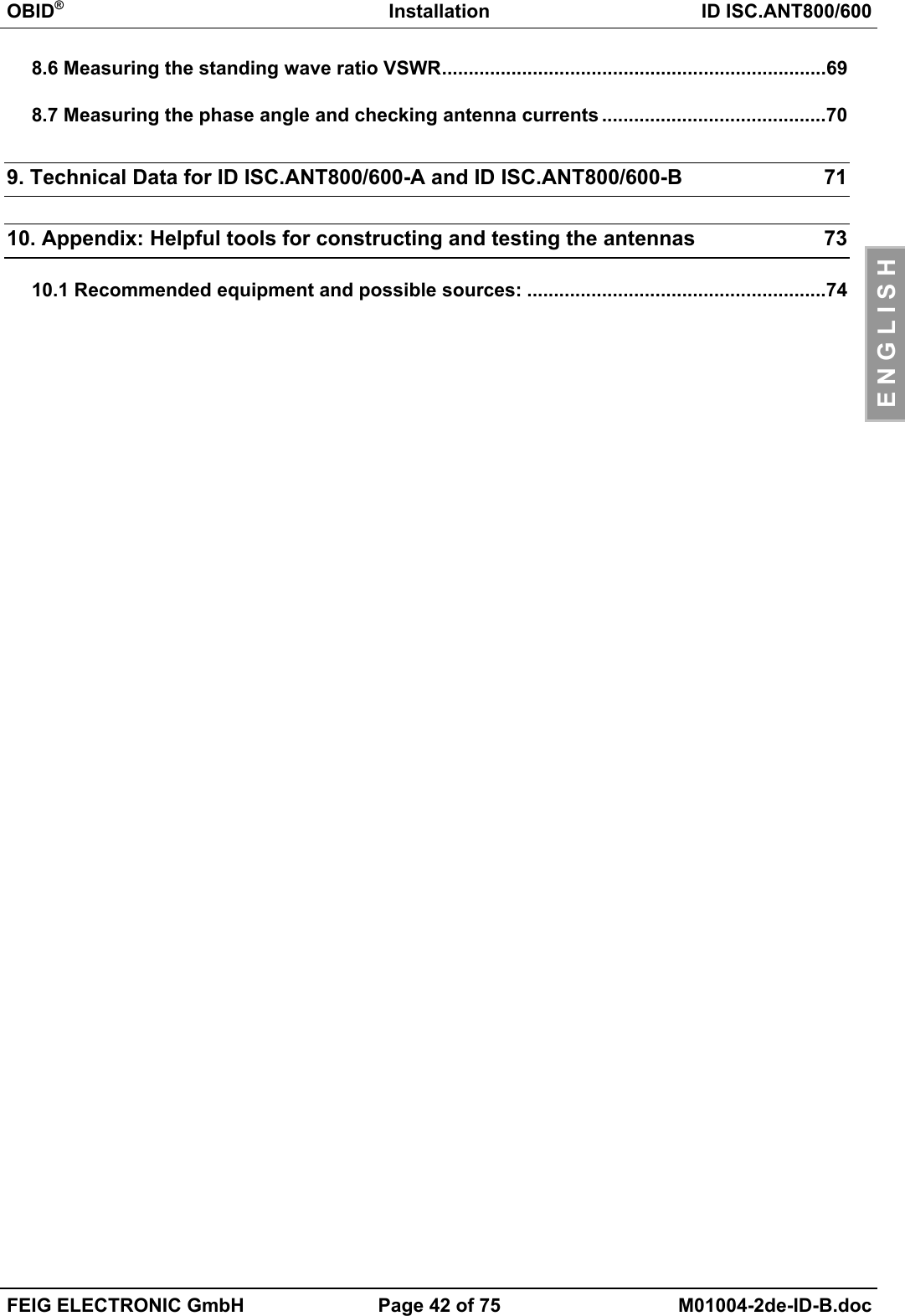
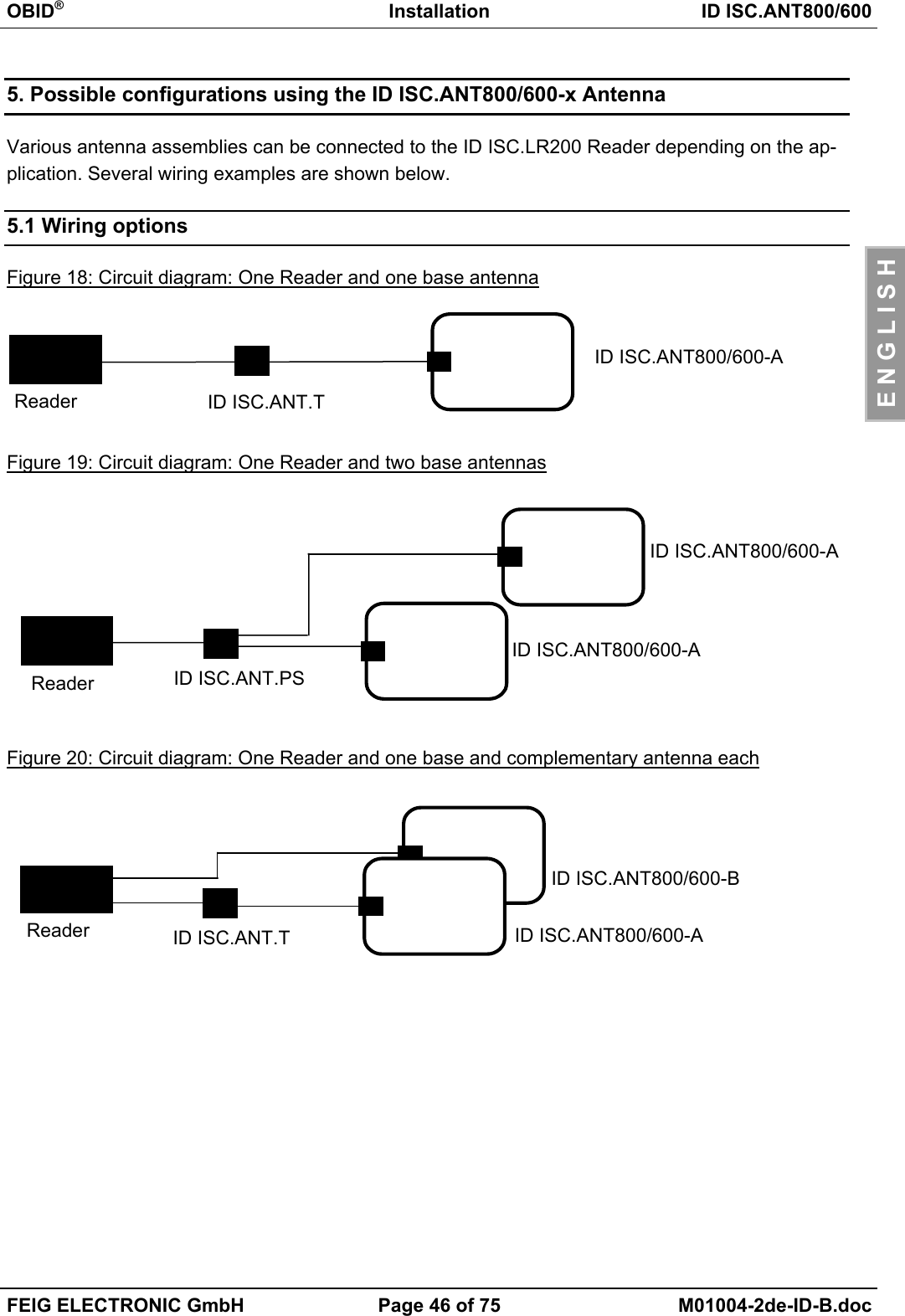
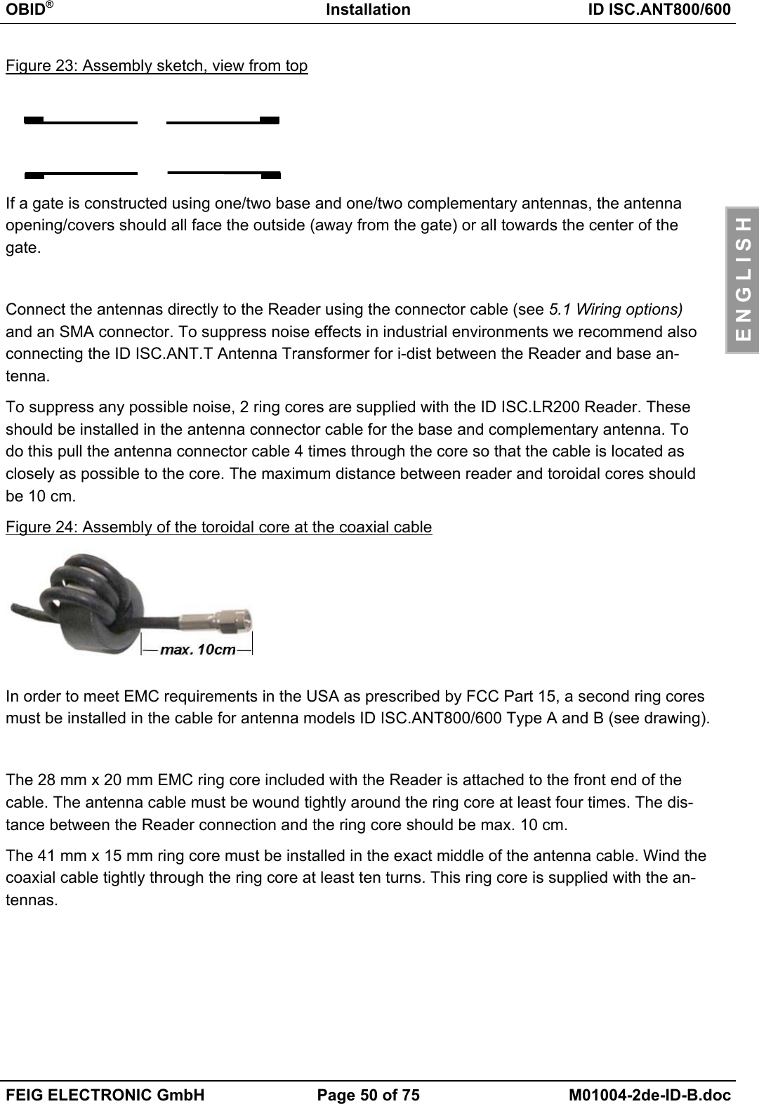
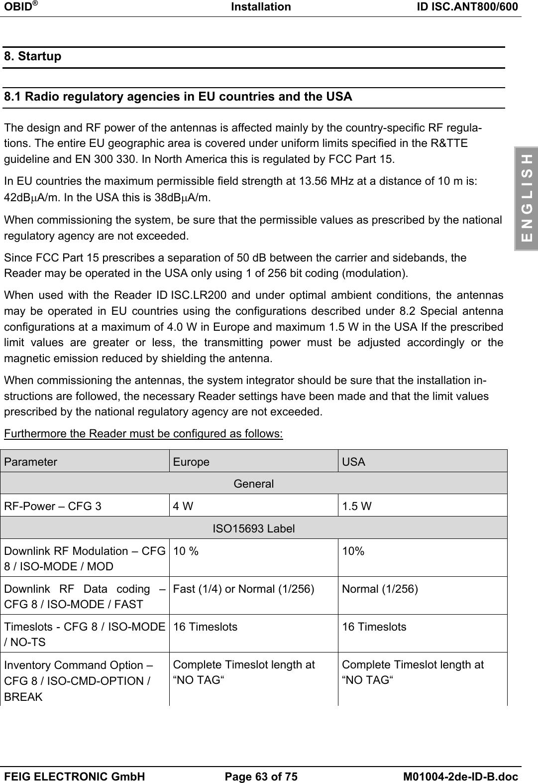
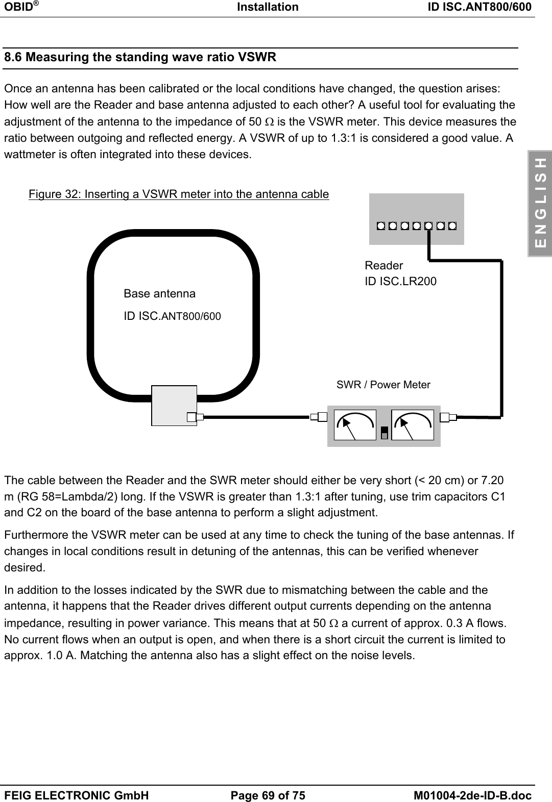
![OBID®Installation ID ISC.ANT800/600FEIG ELECTRONIC GmbH Page 52 of 75 M01004-2de-ID-B.docE N G L I S H6.1 Notes on routing antenna cableWhen routing cable and configuring individual antennas or antenna gates, note the following:• Up to a distance of 50 cm the antenna cable should always be kept vertical to the antenna andfirmly tied down.• If the antenna cable needs to be routed closer along the antenna, maintain a distance of atleast 20 cm.• Always route and fix the cable before tuning. If changes are necessary later check the imped-ance of the base antenna and check the phase and amplitude of the currents of the comple-mentary antenna.• In order to obtain optimum read distances the antenna connector cable should not be short-ened or lengthened. If an extension is absolutely required, use only a 50 Ω cable with a lengthof 2λ (half a wavelength at 13.56 MHz, RG58=7.20 m). A slight loss in sensitivity will likely re-sult.• The antenna cable must be kept a distance of at least 30 cm from any parallel routed powercables.Figure 26: Read distance as a function of antenna cable length in 2λsteps*Label 46 x 75 mm2 over the centre of the antenna, sensitivity / minimum operating fieldHmin=85mA/m rms, parallel orientation to the antenna,. transmitting power 4 W7374757677787980810 3,62 7,24 10,86 14,48 18,1 21,72 25,34 28,96Antenna cable length [m]Range [cm]](https://usermanual.wiki/Feig-Electronic/MR200.Users-Manual-Antenna-2/User-Guide-527653-Page-52.png)
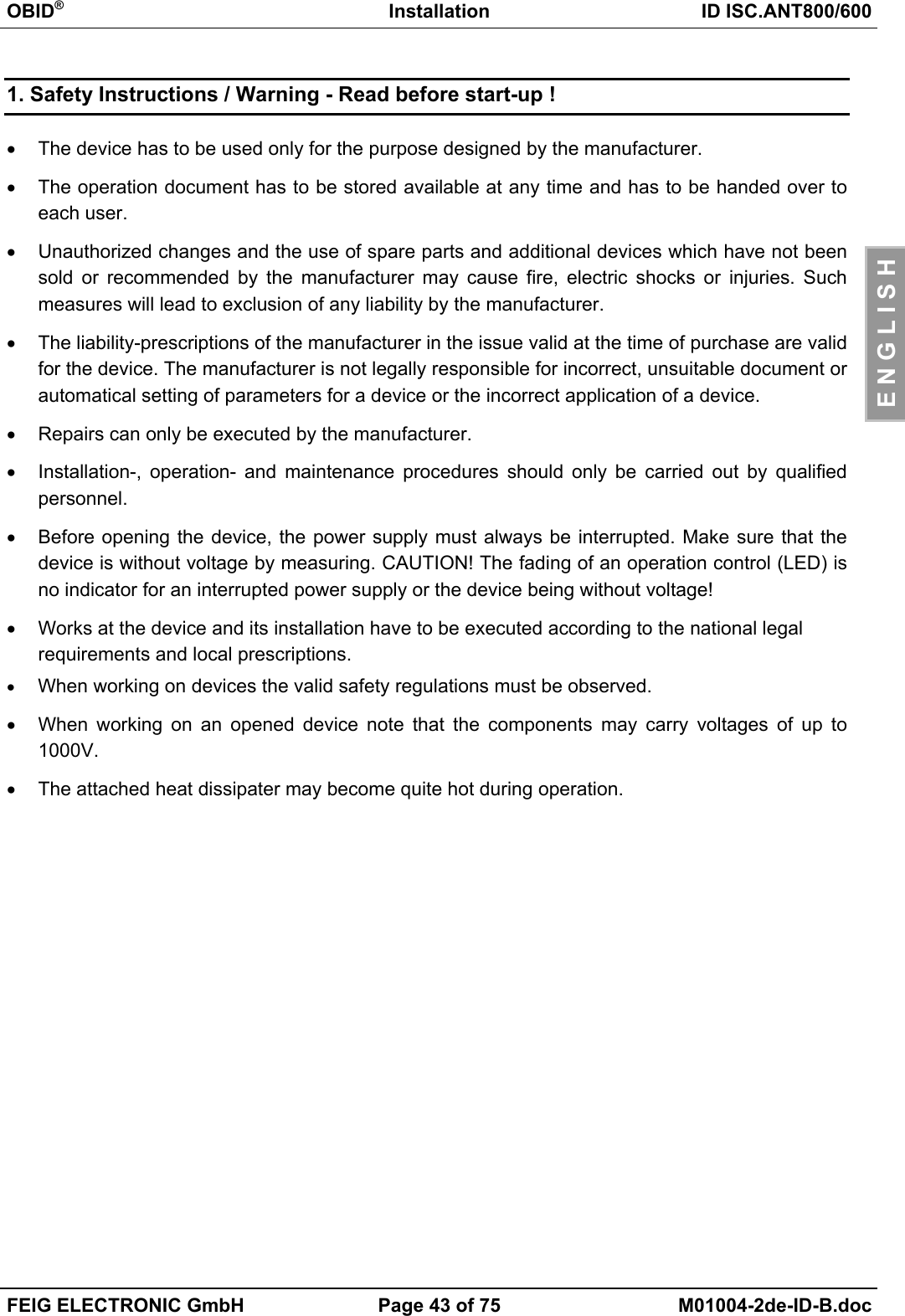
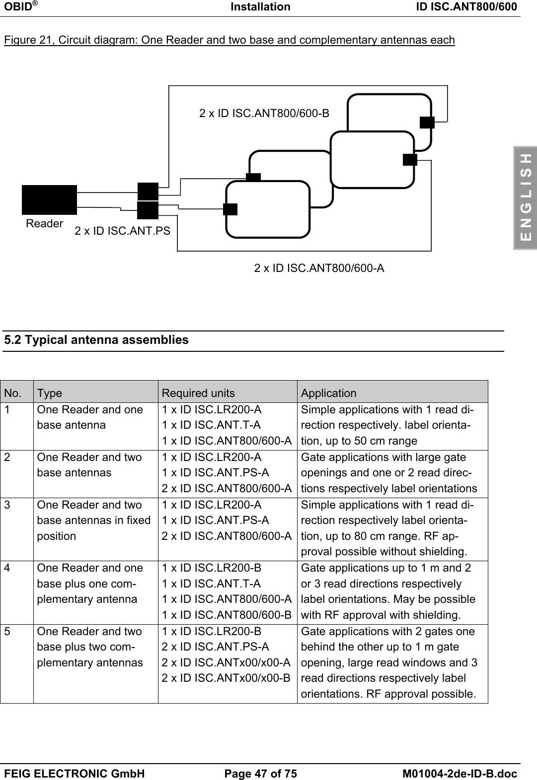
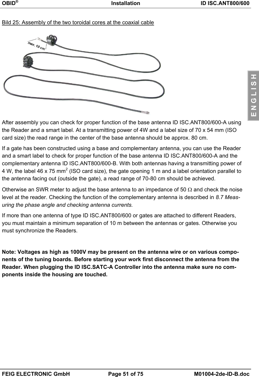
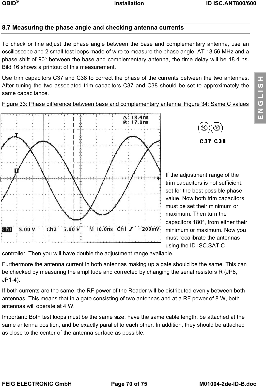
![OBID®Installation ID ISC.ANT800/600FEIG ELECTRONIC GmbH Page 54 of 75 M01004-2de-ID-B.docE N G L I S H7.1 PreparationsStep Procedure Note1Connect the ID ISC.LR200Reader to the PC through theRS232 or RS485 portSee Installation Manual ID ISC.LR2002Install the Demo Software ISC-StartLocated on the OBID® i-scan CD-ROM3Run the ISCStart program4Open the COM port settings5Check the COM port settingsand confirm by clicking on OK.6Now open the menu File – New- Reader7Select ID ISCLR and click onOK8Select COM: x [Baud38400......]9Click on Commands](https://usermanual.wiki/Feig-Electronic/MR200.Users-Manual-Antenna-2/User-Guide-527653-Page-54.png)
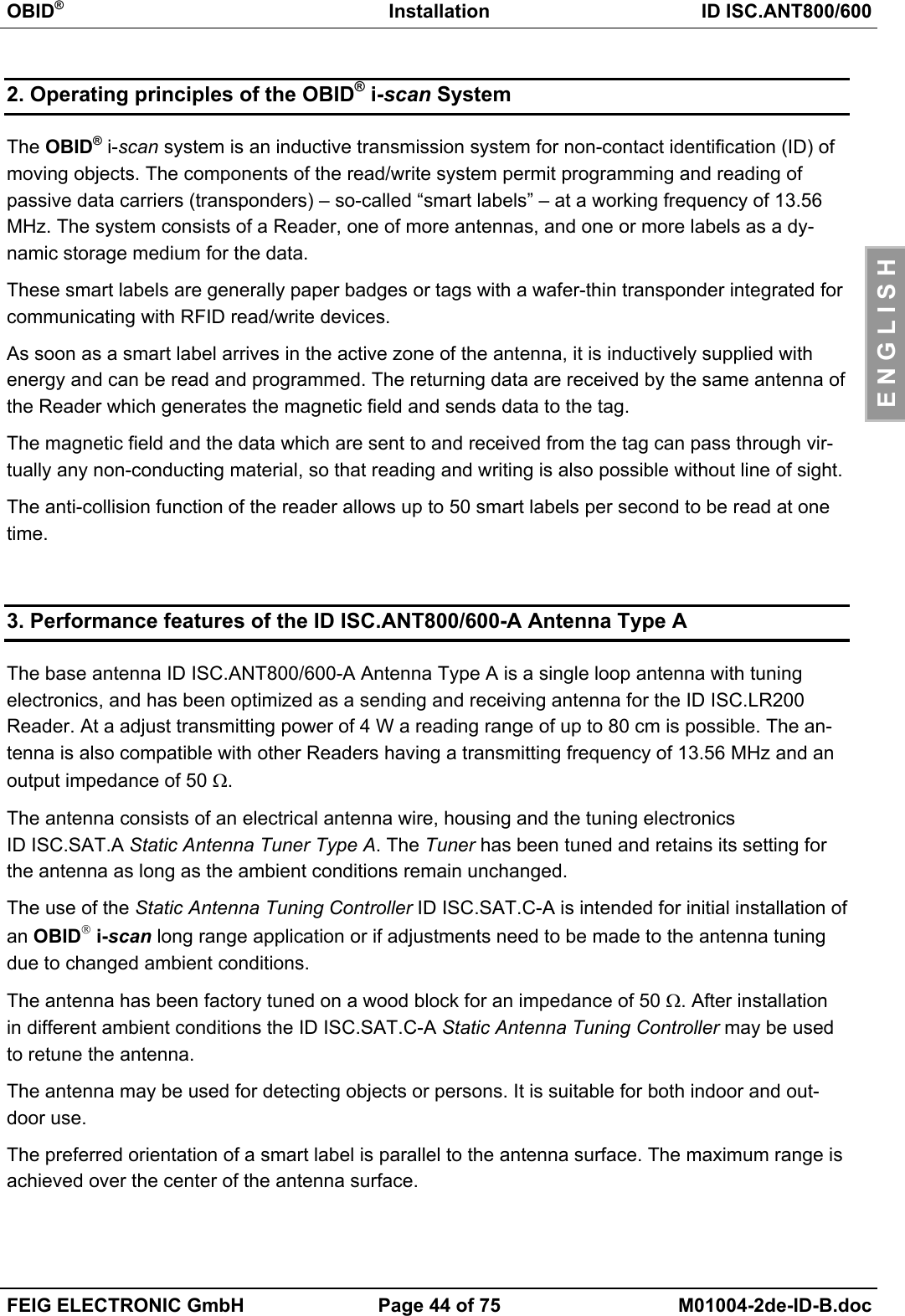
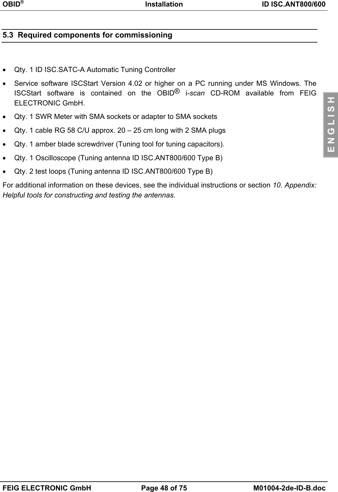
![OBID®Installation ID ISC.ANT800/600FEIG ELECTRONIC GmbH Page 55 of 75 M01004-2de-ID-B.docE N G L I S H10 Select Baudrate Detec-tion[0x52] command11 Click on Send12 The program tests all possiblebaud rates. It stops as soon asthe baud rate set on the Readerhas been detected (default38400 / 8E1) and confirms withOK13 Click on Configuration14 Select ID ISCLR Configura-tion.15 Select destination memoryEEPROM instead of RAM.16 Click on Reset [0x83] to set theReader to the default configu-ration.17 Click on Read to load theReader configuration into thePC and to load the ISCStartprogram.](https://usermanual.wiki/Feig-Electronic/MR200.Users-Manual-Antenna-2/User-Guide-527653-Page-55.png)
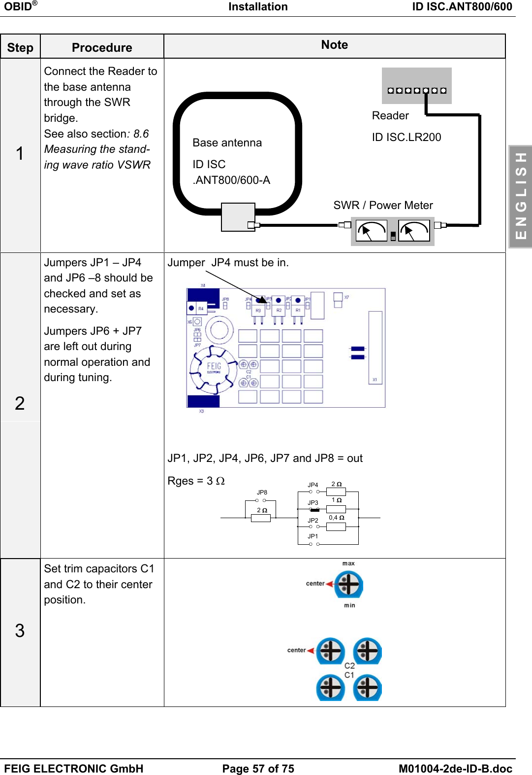
![OBID®Installation ID ISC.ANT800/600FEIG ELECTRONIC GmbH Page 58 of 75 M01004-2de-ID-B.docE N G L I S H4Click on Commandsat the ISCStart Pro-gram Window5Select the command[0x6F] Base AntennaTunning] and click onSend to send all thesettings.6Now connect the StaticAntenna Tuning Con-troller ID ISC.SAT.C-Ato the antenna tuner ofthe base antenna andpress the “Start“ keyon the controller.The tuning processtakes several seconds.When completed, thegreen LED will comeon for 4 seconds..Tuning mode: Is activated by holding down the Start key greaterthan two seconds (< 2 sec).Control mode: Is activated by briefly pressing the Start keyshorter than two seconds (< 2 sec).7The controller runsthen automaticallyturns off and can thenbe unplugged.Important:Do not unplug the controller beforethe green LED has gone out!Now you may begin tuning the complementary antenna.](https://usermanual.wiki/Feig-Electronic/MR200.Users-Manual-Antenna-2/User-Guide-527653-Page-58.png)
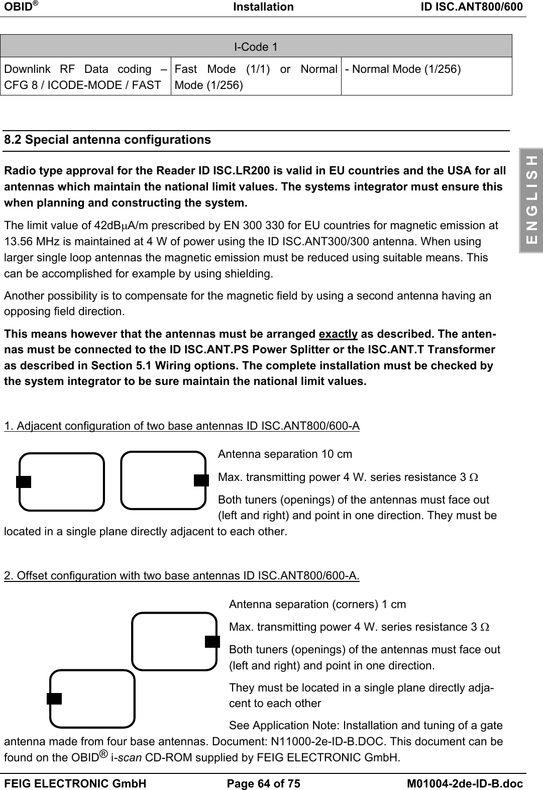
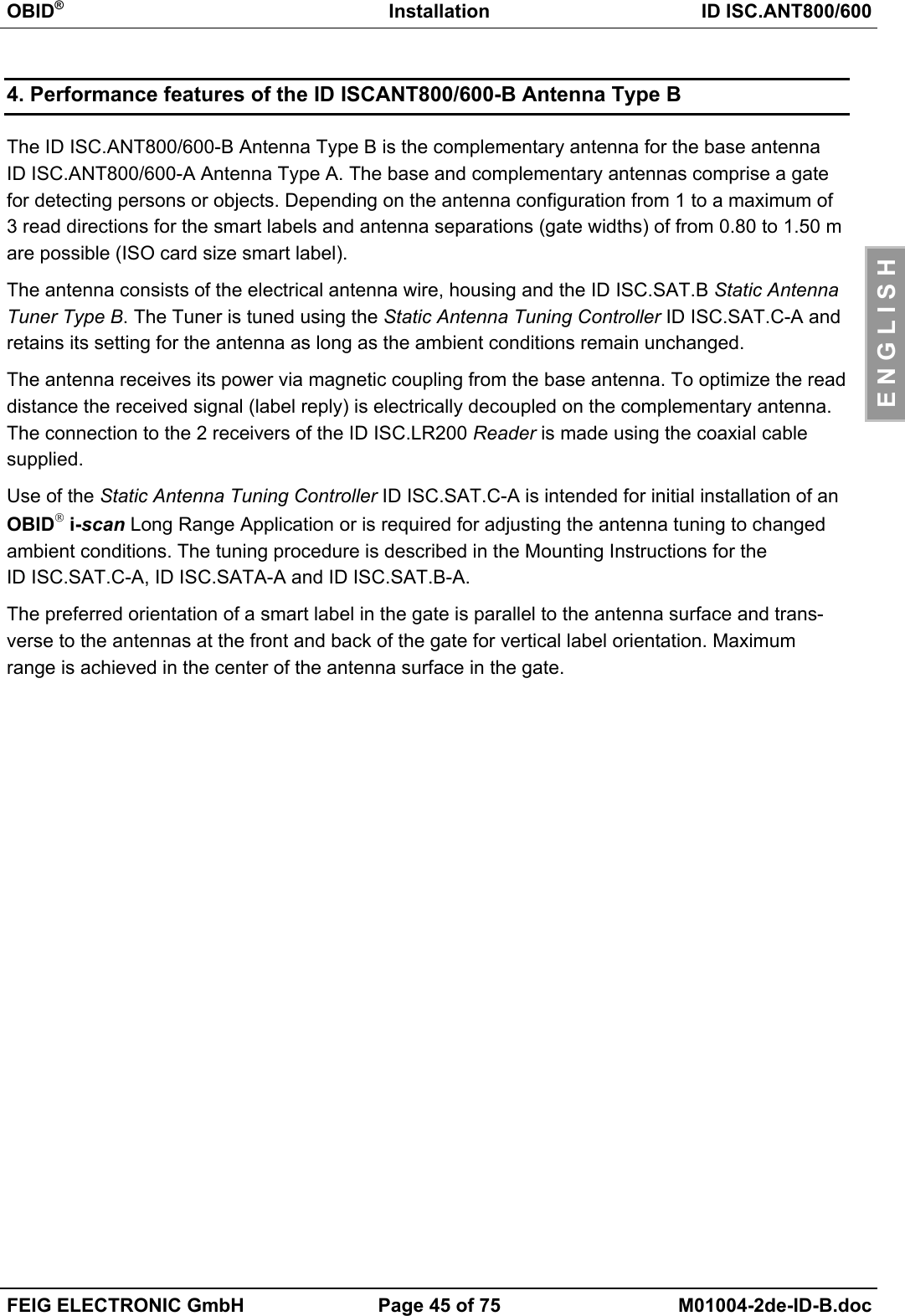
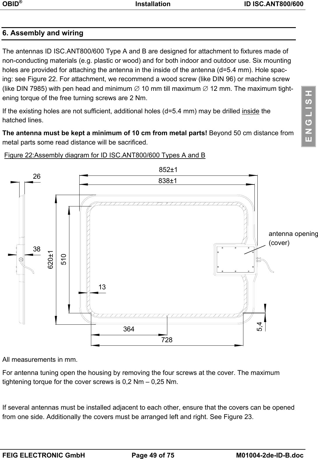
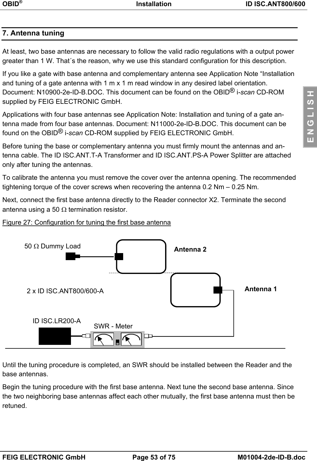
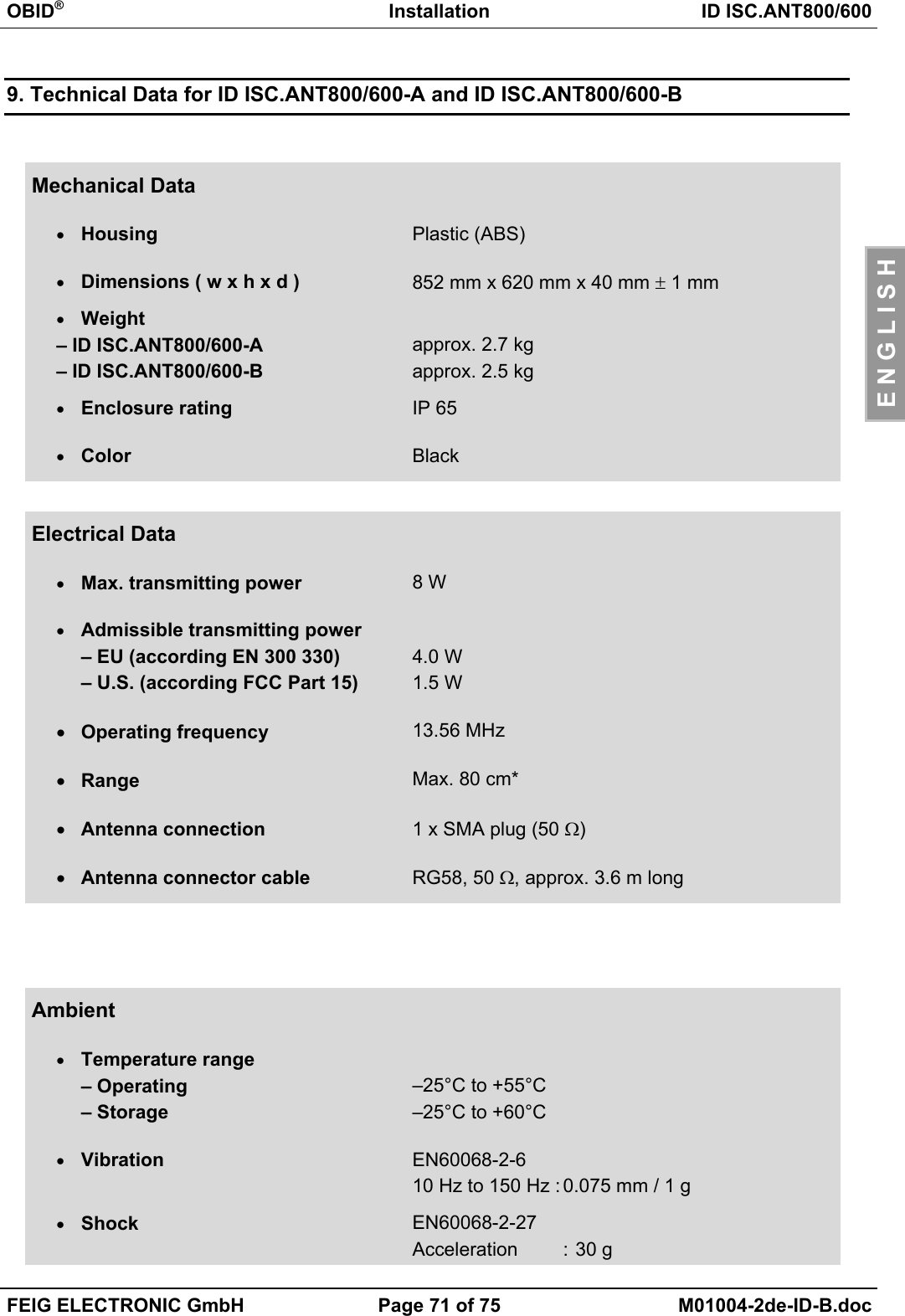
![OBID®Installation ID ISC.ANT800/600FEIG ELECTRONIC GmbH Page 66 of 75 M01004-2de-ID-B.docE N G L I S H8.3 The effect of transmitting power on reading rangeThe reading range of an antenna depends on the antenna itself, the Reader, the smart label andthe transmitting power set for the Reader. Since the smart label receives its power from the mag-netic field generated by the antenna and the field strength drops off sharply with increasing dis-tance between the Reader and antenna, the emitted transmitting power for a given antenna has agreat influence on the read range.Figure 29: Reading range* of an ID ISC.ANT800/600-A as a function of transmitting power*Label 46 x 75 mm2, over the centre of the antenna, sensitivity / minimum operating fieldHmin=85mA/m rms, parallel orientation to the antenna.A transmitting power above 8 W may, depending on ambient temperature, result in excessiveheating of the antenna and may destroy the antenna tuner.6065707580859095012345678910P [W]Range [cm]](https://usermanual.wiki/Feig-Electronic/MR200.Users-Manual-Antenna-2/User-Guide-527653-Page-66.png)
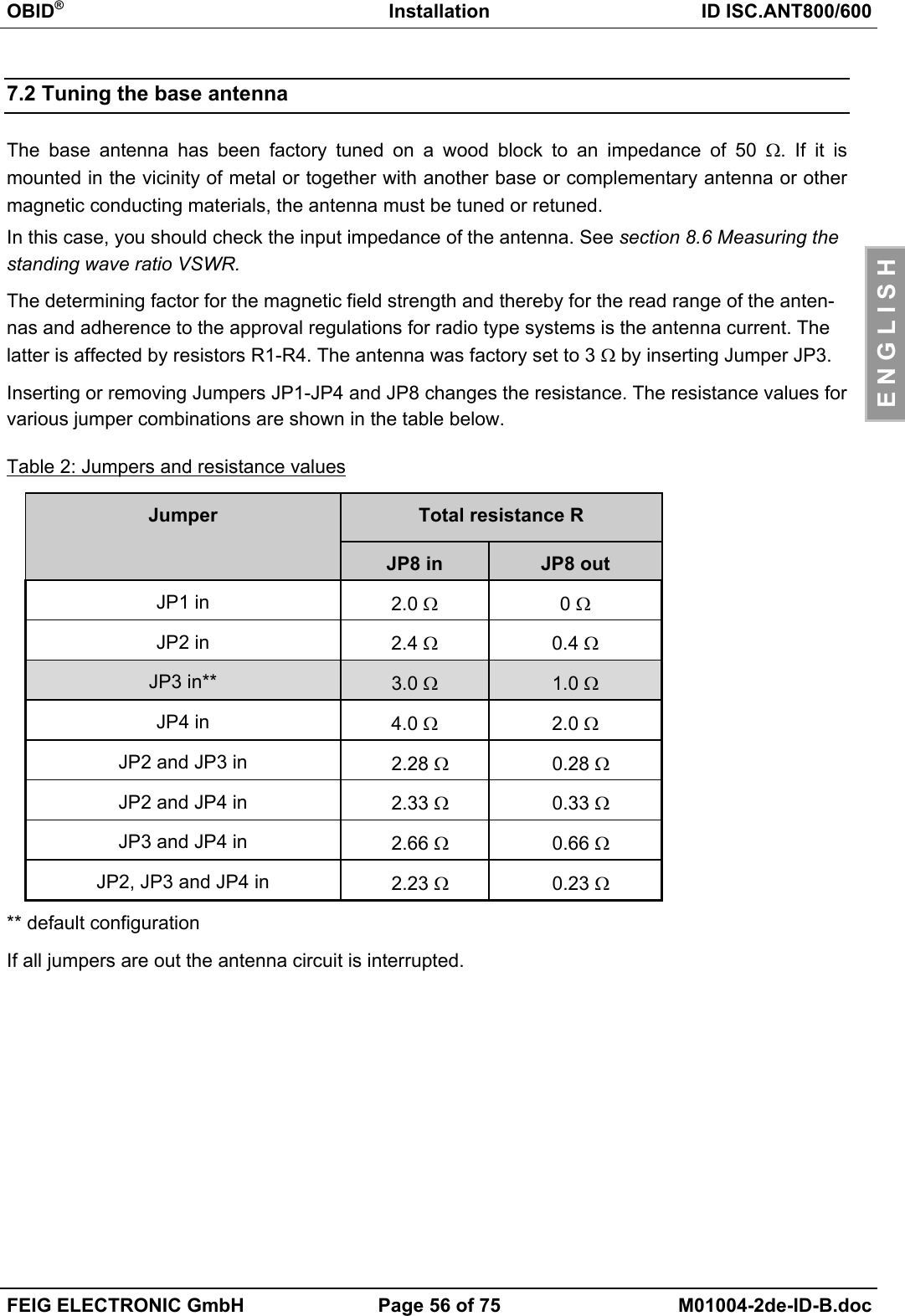
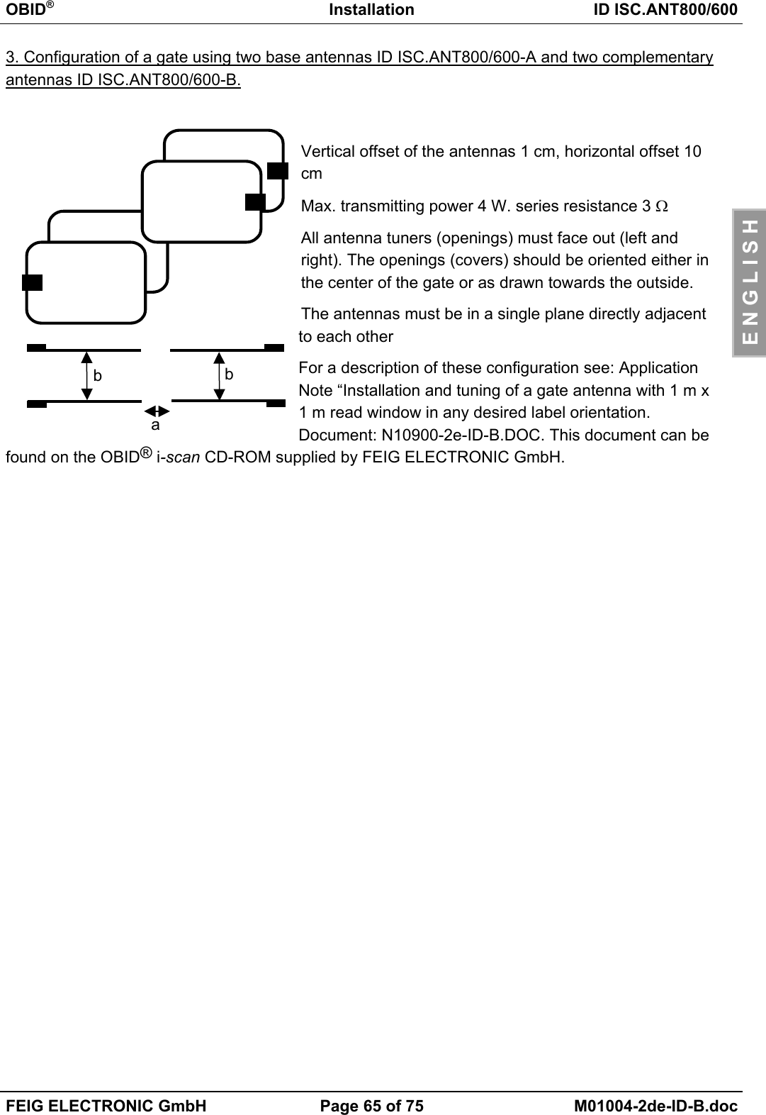
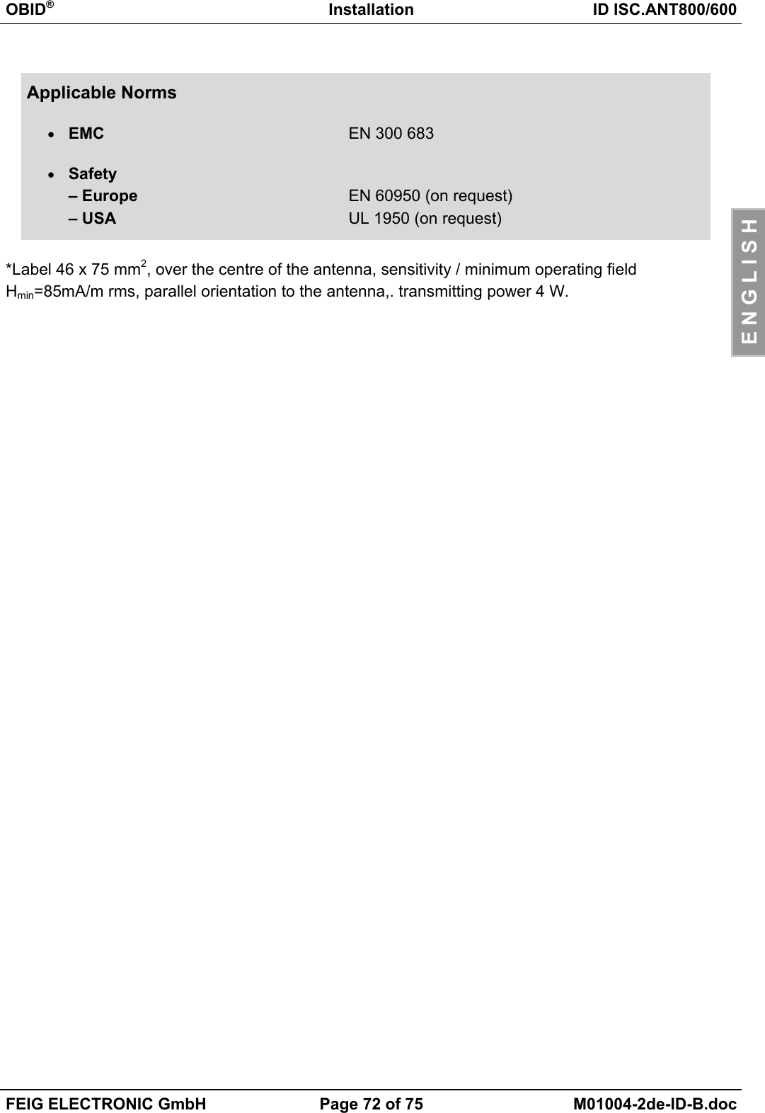
![OBID®Installation ID ISC.ANT800/600FEIG ELECTRONIC GmbH Page 67 of 75 M01004-2de-ID-B.docE N G L I S H8.4 The effect of metal on reading rangeMetal and other conducting materials cannot be penetrated by a magnetic field. The field lines andinductance of the antenna are changed, which has a great effect on the effective range. The field isalso attenuated by mutual inductance and eddy currents in the metal.The change in inductance can usually be compensated by using the tuning unit. Figure 30 showsthe effect of a metal plate on the antenna with (upper line) and without compensation.Figure 30: Read range* as a function of proximity to metal No compensation Compensated*Label 46 x 75 mm2, over the centre of the antenna, sensitivity / minimum operating fieldHmin=85mA/m rms, parallel orientation to the antenna,. transmitting power 4 WIf proximity to metal is unavoidable, note the following:• Keep a minimum distance of 10 cm between metal and the antenna. Above 30 cm significantread distance is sacrificed. Above 50 cm from metal there is no longer a measurable effect.• The metal parts must not be permitted to form closed loops or circuits. These should be electri-cally isolated at one point if necessary.• The metal parts in direct proximity to the antenna should be grounded in star configuration witha good HF connection.3035404550556065707580850 102030405060Distance to metal plate [cm]Range [cm]](https://usermanual.wiki/Feig-Electronic/MR200.Users-Manual-Antenna-2/User-Guide-527653-Page-67.png)
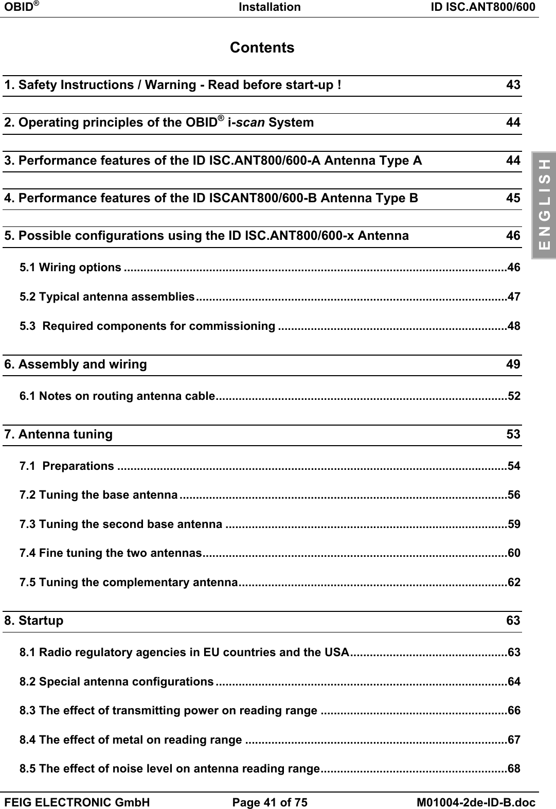
![OBID®Installation ID ISC.ANT800/600FEIG ELECTRONIC GmbH Page 68 of 75 M01004-2de-ID-B.docE N G L I S H8.5 The effect of noise level on antenna reading rangeIn order for the smart label to be reliably read by the receiver even at low signal levels, you mustprevent or eliminate noise as much as possible. The amplitude of the noise levels can be checkedbased on the noise level on the ID ISC.LR200 Reader. Critical are not the absolute measured val-ues but the difference between Umax and Umin.This has been simulated and graphically represented for 4 W transmitting power in the figure be-low.Figure 31: Reading range* as a function of noise level*Label 46 x 75 mm2 over the centre of the antenna, sensitivity / minimum operating fieldHmin=85mA/m rms, parallel orientation to the antenna,. transmitting power 4 WGood values for Umax-Umin with base antennas are 20mV, or 40mV for gate antennas.Possible causes of excessively high noise levels:• Poor (HF-) connections between Reader and antenna.• Improper cable routing between antenna and Reader• Poorly tuned antenna• Noise signals from other electronic devices or transmitters.• Noise in the Reader power supply• Noise signals from other cables in the vicinity of the cable to and from the Reader• Metal near the antenna304050607080900 100 200 300 400 500Umax-Umin [mV]Range [cm]](https://usermanual.wiki/Feig-Electronic/MR200.Users-Manual-Antenna-2/User-Guide-527653-Page-68.png)
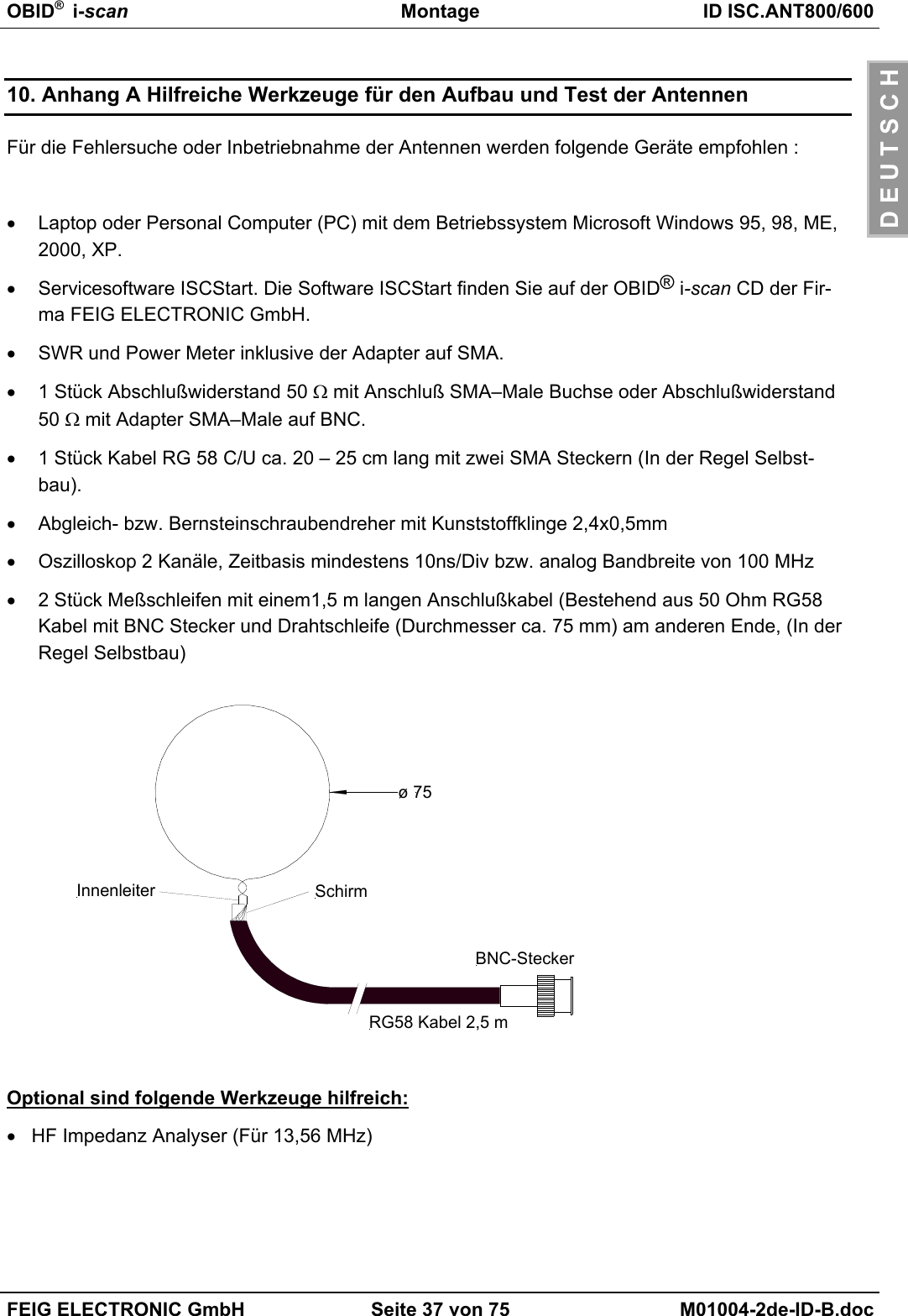
![OBID®Installation ID ISC.ANT800/600FEIG ELECTRONIC GmbH Page 73 of 75 M01004-2de-ID-B.docE N G L I S H10. Appendix: Helpful tools for constructing and testing the antennasThe following equipment is recommended for tuning, troubleshooting and commissioning the an-tennas:• Laptop or personal computer (PC) running under Microsoft Windows 95, 98, ME, 2000, XP.• Service software ISCStart (V4.02 or higher). This software can be found on the OBID® i-scanCD-ROM supplied by FEIG ELECTRONIC GmbH..• SWR and Power Meter including SMA connectors (female) or appropriate adapters.• Qty. 1 cable RG 58 C/U approx. 20 – 25 cm (7.8 – 9.8 in) long with two male SMA plugs (gen-erally self-assembled).• Suitable screwdriver for antenna tuning, with plastic blade, 2.4x0.5mm.• 2-channel oscilloscope, sweep rate at least 10ns/Div or analog bandwidth of 100 MHz.• Qty. 2 test loops 1.5 m long (consisting of 50 Ohm, RG58 cable with BNC plug and wire loop(diameter approx. 75 mm [30 in]) at the other end (generally self-assembled).The following tools are optional but helpful:• HF Impedance Analyzer (for 13.56 MHz)screencentre conductorBNC-plug, maleRG58 cable 2,5 mø 75](https://usermanual.wiki/Feig-Electronic/MR200.Users-Manual-Antenna-2/User-Guide-527653-Page-73.png)