Feig Electronic MR200 Inductive Reader User Manual M40400 1de ID B
Feig Electronic GmbH Inductive Reader M40400 1de ID B
UserManual.wiki
>
Feig Electronic
>
MR200 User Manual
>
Users Manual
Contents
1.
Users Manual
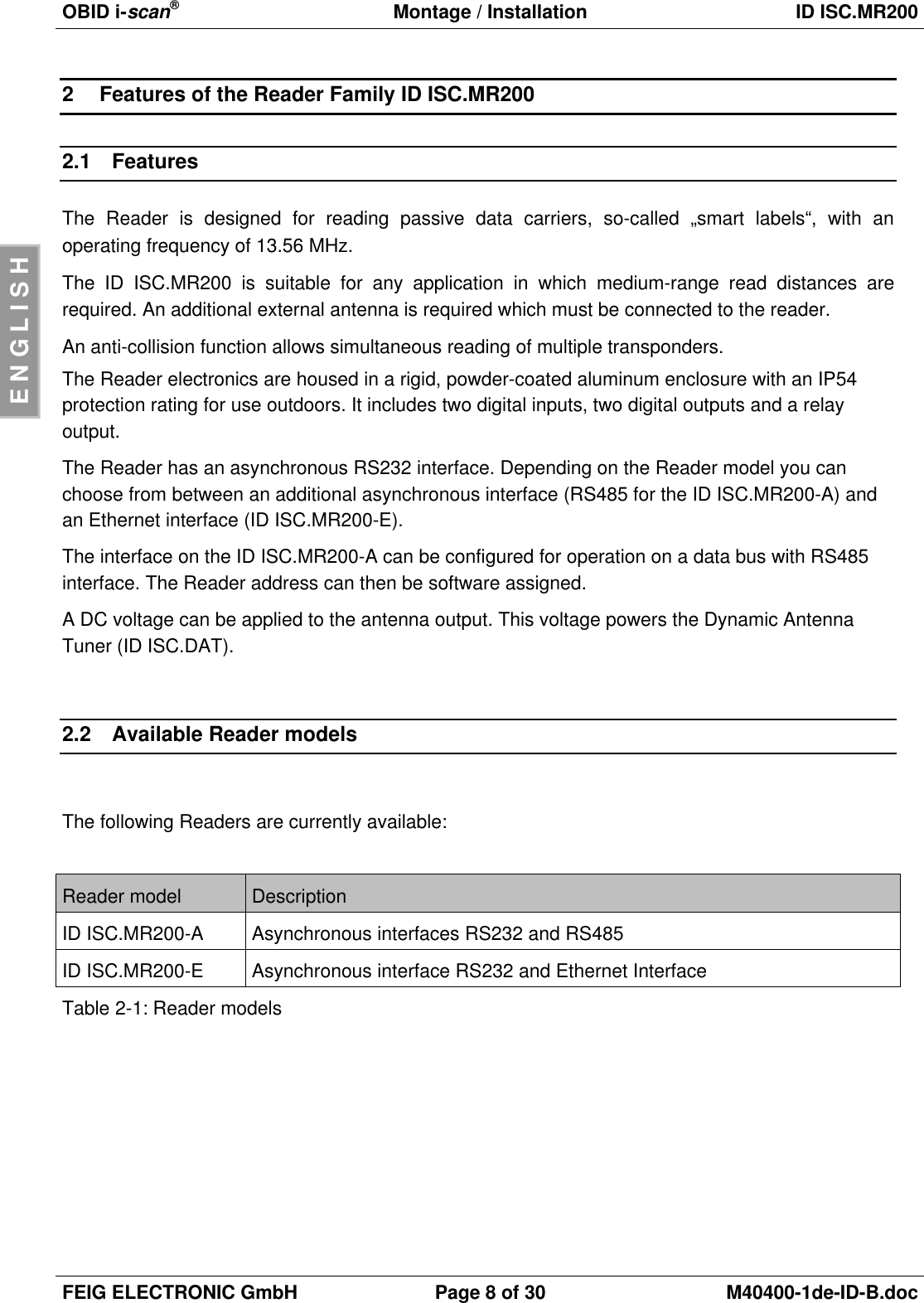
2.
Users Manual Antenna 1
3.
Users Manual Antenna 2
Users Manual
Navigation menu
Upload a User Manual
Namespaces
Wiki Guide
HTML
PDF
Info
Views
User Manual
Discussion / Help
Navigation
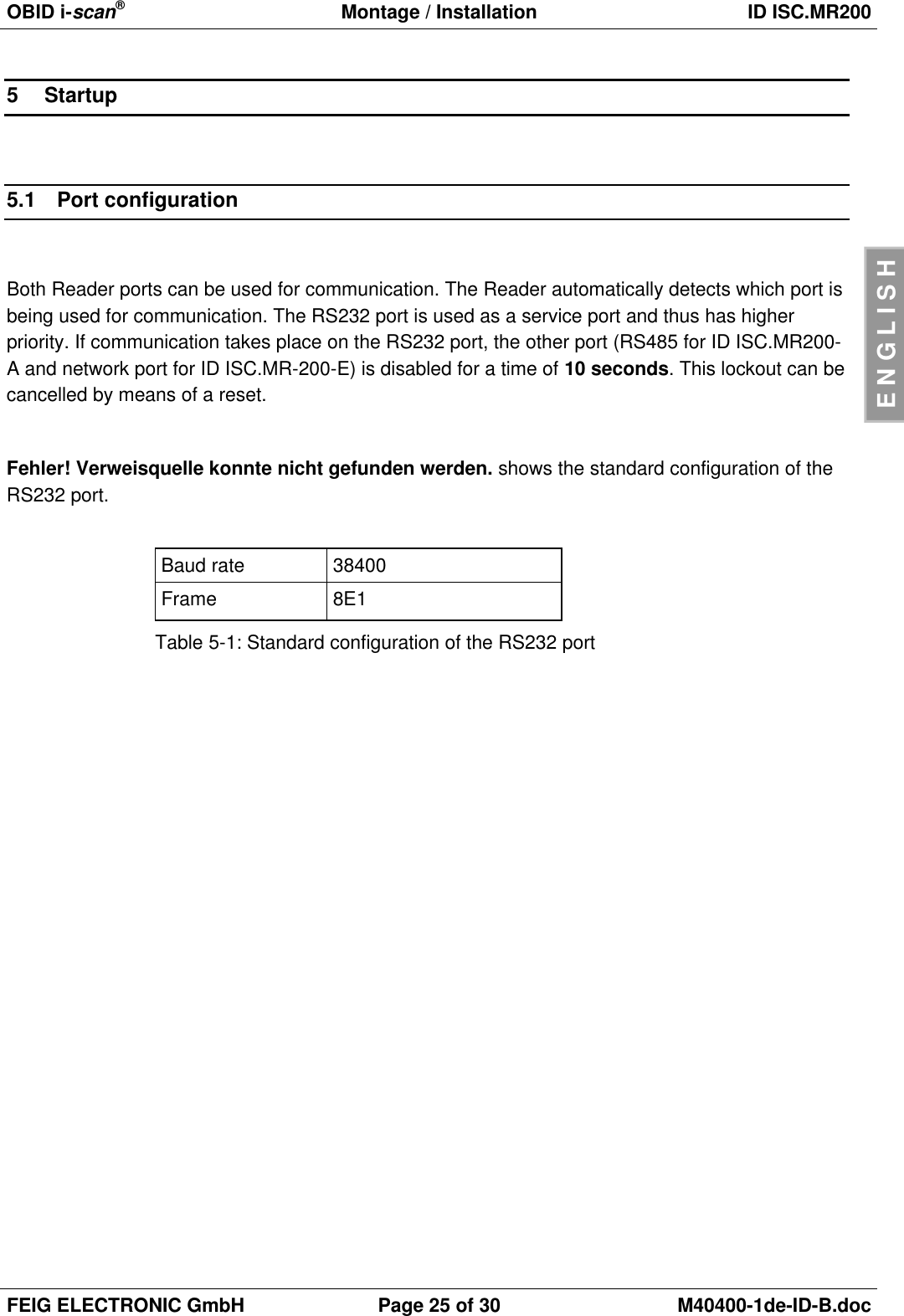
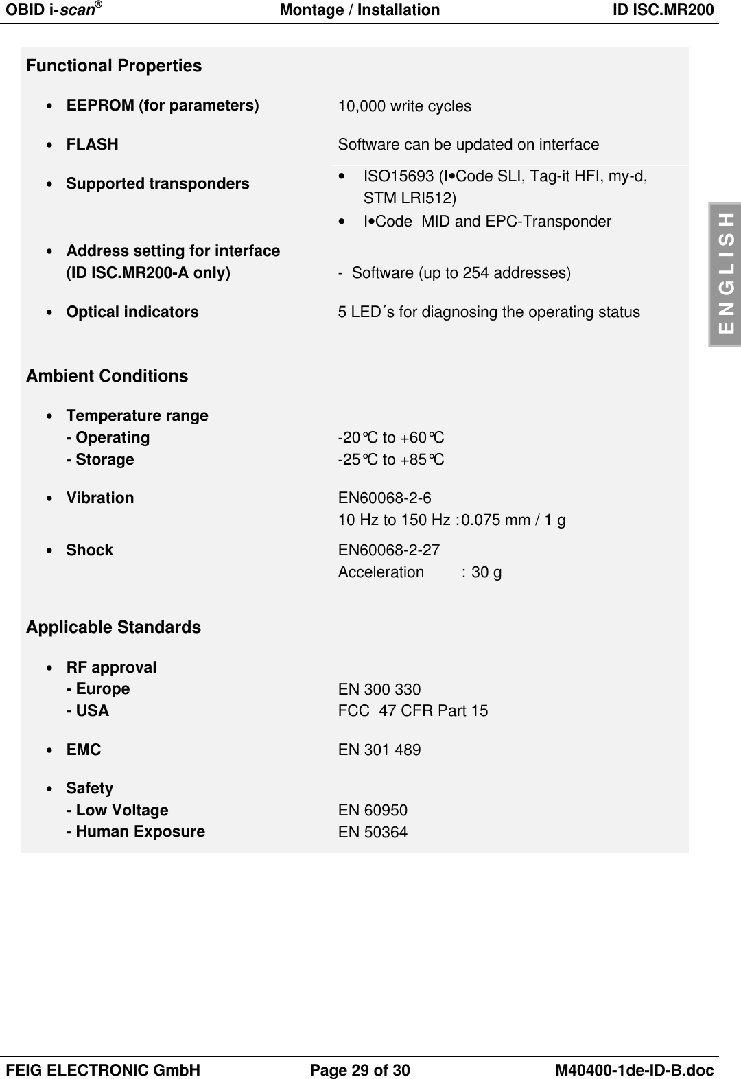
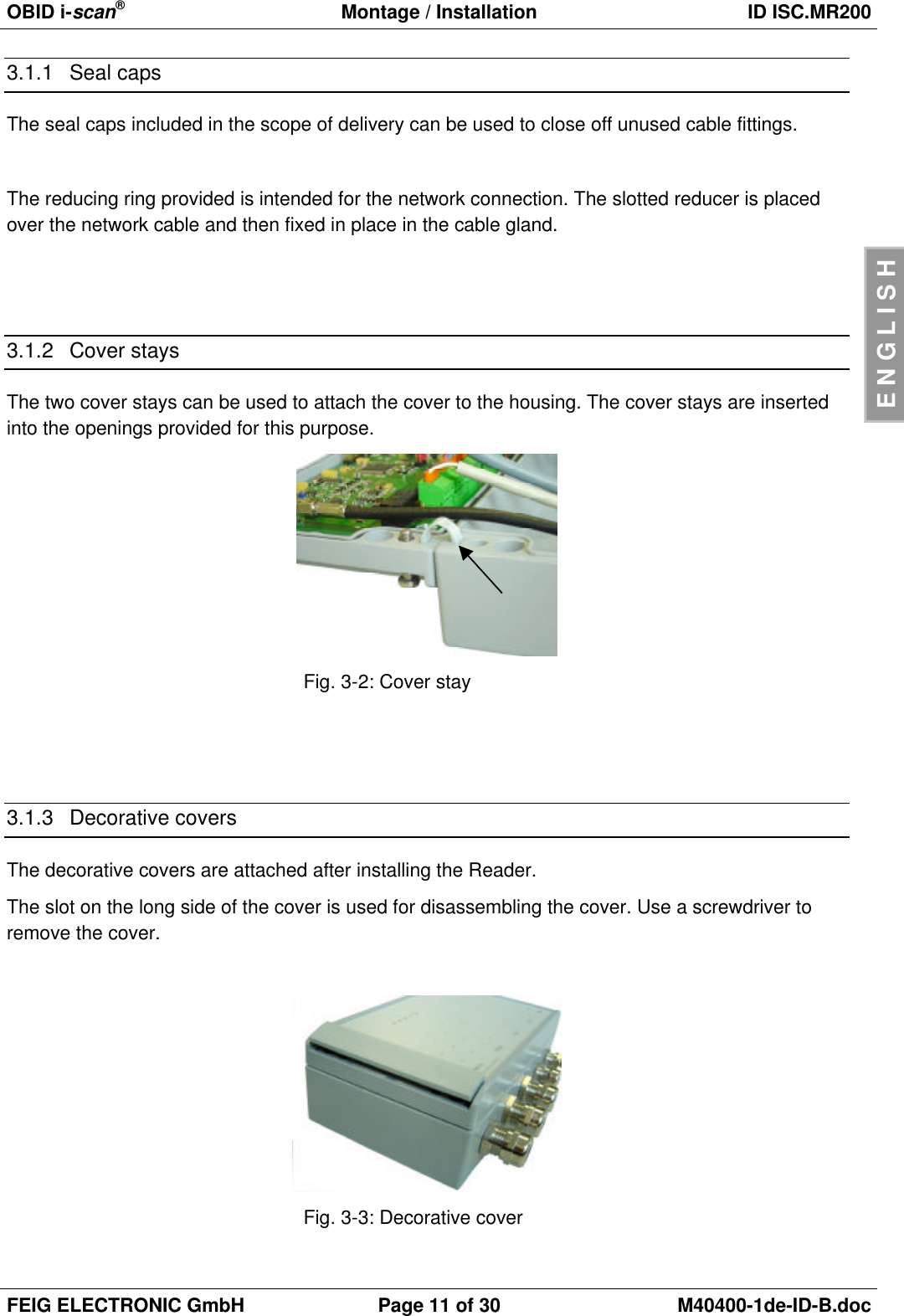
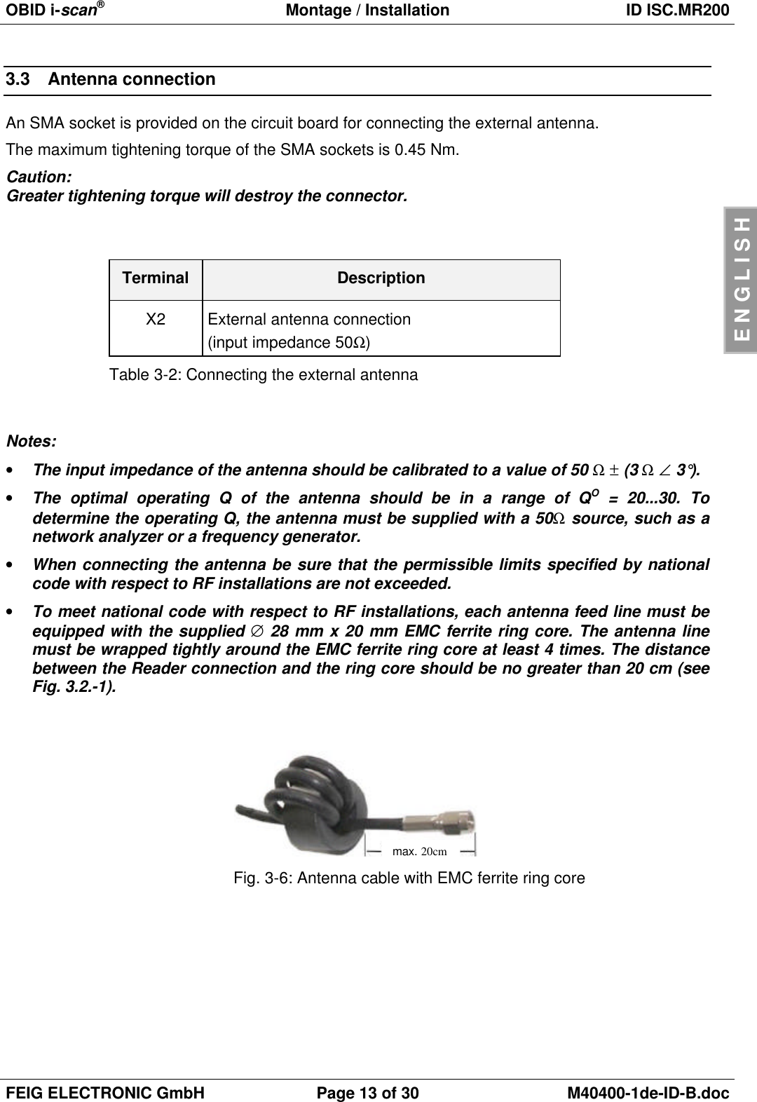
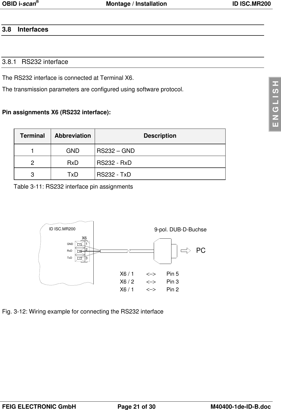
![OBID i-scan®Montage / Installation ID ISC.MR200FEIG ELECTRONIC GmbH Page 10 of 30 M40400-1de-ID-B.docENGLISH3Installation and Wiring3.1 InstallationThe Reader is designed for wall mount, including outdoors. Holes are provided in the housing forwall attachment. The housing does not need to be opened for installation on a wall (see Fig. 1).Fig. 3-1: Housing ID ISC.MR200Cable gland Size Clamping range[mm] Description1M 16 4.5 – 10 Antenna cable2M 16 4.5 – 10 Relay / Outputs3M 16 4.5 – 10 Inputs4M 12 3.5 – 7 Interface (serial)5M 12 3.5 – 7 Supply voltage6M 25 9 – 17 Ethernet Interface (model –E only)Table 3-1: ID ISC.MR200 cable glands20011018260634521Antenna Output Input Com PowerRFID by FEIG ELECTRONIC](https://usermanual.wiki/Feig-Electronic/MR200.Users-Manual/User-Guide-527649-Page-10.png)
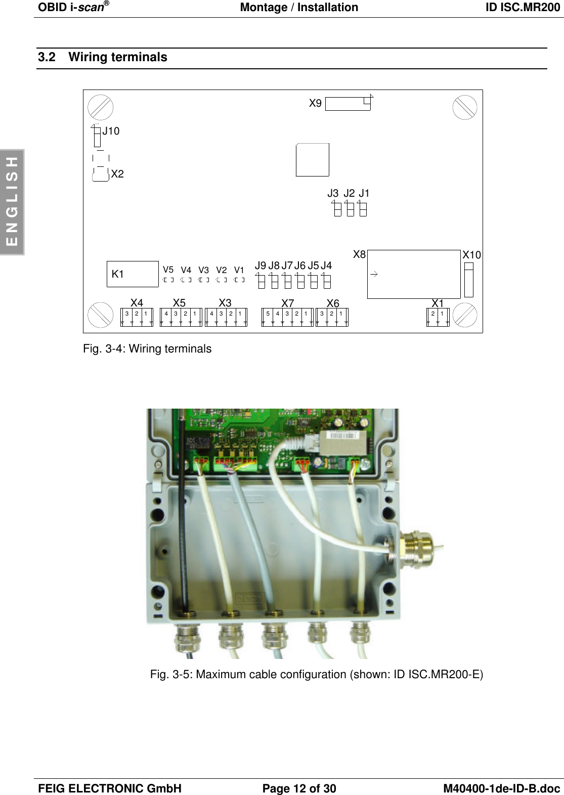
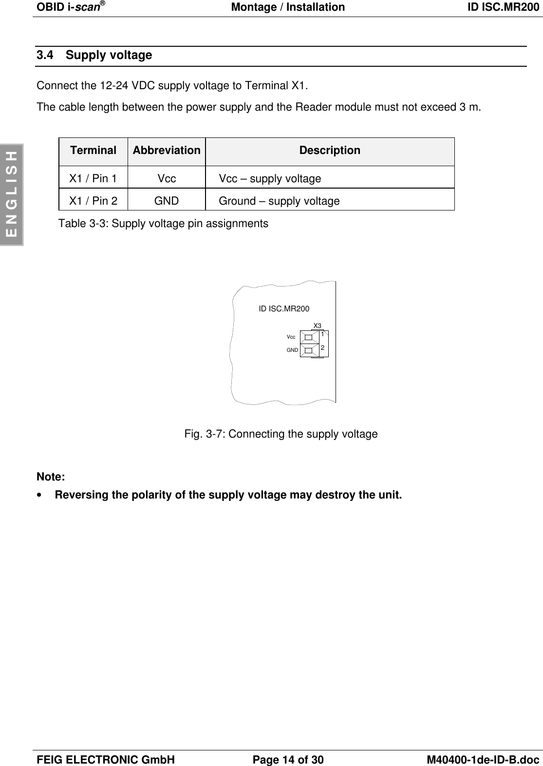
![OBID i-scan®Montage / Installation ID ISC.MR200FEIG ELECTRONIC GmbH Page 24 of 30 M40400-1de-ID-B.docENGLISH4Operating and Display Elements4.1 LED´sFehler! Verweisquelle konnte nicht gefunden werden. shows the configuration of the LED’s.Abbreviation DescriptionLED V1 (green) "RUN-LED"-Indicates proper running of the internal Reader software-Flashing frequency approx. 1 HzLED V2 (blue) Diagnostic 1: RF communication / EEPROM status-Short flashing indicates errorless communication with atransponder on the RF interface-Flashes alternately with V1 after the reset following a softwareupdate-Flashes alternately with V1 if an error in reading theparameters occurred following a resetLED V3 (yellow Diagnostic 2: Host communication-Short flashing indicates a protocol is being sent to the host.LED V4 (yellow) Diagnostic 3: for future applicationsLED V5 (red) Diagnostic 4: Reader initializing / RF error-Comes on during Reader initializing following power-on or aftera reset.-Comes on when there is an error in the RF section of theReader.The error type can be read via software using the ReaderDiagnostic command [0x6E].Table 4-1: LED configuration](https://usermanual.wiki/Feig-Electronic/MR200.Users-Manual/User-Guide-527649-Page-24.png)