Feig Electronic MR200 Inductive Reader User Manual M40400 1de ID B
Feig Electronic GmbH Inductive Reader M40400 1de ID B
Contents
- 1. Users Manual
- 2. Users Manual Antenna 1
- 3. Users Manual Antenna 2
Users Manual
MONTAGE
INSTALLATION
public (B)
2005-02-02
M40400-1de-ID-B.doc
OBIDi-scan®
ID ISC.MR200
(deutsch / english)

OBID i-scan®Montage / Installation ID ISC.MR200
FEIG ELECTRONIC GmbH Seite 2von 30 M40400-1de-ID-B.doc
DEUTSC H
deutsche Version
english version from page 4
ENGLISH

OBID i-scan®Montage / Installation ID ISC.MR200
FEIG ELECTRONIC GmbH Page 4of 30 M40400-1de-ID-B.doc
ENGLISH
Note
Copyright 2005 by
FEIG ELECTRONIC GmbH
Lange Strasse 4
D-35781 Weilburg-Waldhausen
Tel.: +49 6471 3109-0
http://www.feig.de
With the edition of this document, all previous editions become void. Indications made in this manual may be
changed without previous notice.
Copying of this document, and giving it to others and the use or communication of the contents thereof are
forbidden without express authority. Offenders are liable to the payment of damages. All rights are reserved
in the event of the grant of a patent or the registration of a utility model or design.
Composition of the information in this manual has been done to the best of our knowledge. FEIG
ELECTRONIC GmbH does not guarantee the correctness and completeness of the details given in this
manual and may not be held liable for damages ensuing from incorrect or incomplete information. Since,
despite all our efforts, errors may not be completely avoided, we are always grateful for your useful tips.
The installation instructions given in this manual are based on advantageous boundary conditions. FEIG
ELECTRONIC GmbH does not give any guarantee promise for perfect function in cross environments.
FEIG ELECTRONIC GmbH assumes no responsibility for the use of any information contained in this
manual and makes no representation that they free of patent infringement. FEIG ELECTRONIC GmbH does
not convey any license under its patent rights nor the rights of others.
OBID®and OBID i-scan®are registered trademarks of FEIG ELECTRONIC GmbH.
my-d®is a registered trademark of Infineon Technologies AG
I-CODE®is a registered trademark of Philips Electronics N.V.
Tag-itTMis a registered trademark of Texas Instruments Incorporated.

OBID i-scan®Montage / Installation ID ISC.MR200
FEIG ELECTRONIC GmbH Page 5of 30 M40400-1de-ID-B.doc
ENGLISH
Contents
1Safety Instructions / Warning - Read before start-up ! 7
2Features of the Reader Family ID ISC.MR200 8
2.1 Features.......................................................................................................................8
2.2 Available Reader models............................................................................................8
2.3 Scope of delivery ........................................................................................................9
3Installation and Wiring 10
3.1 Installation.................................................................................................................10
3.1.1 Seal caps ....................................................................................................................11
3.1.2 Cover stays.................................................................................................................11
3.1.3 Decorative covers .......................................................................................................11
Wiring terminals......................................................................................................................12
3.3 Antenna connection..................................................................................................13
3.4 Supply voltage...........................................................................................................14
3.5 DC voltage on the RF antenna terminal X2 .............................................................16
3.6 Inputs.........................................................................................................................17
3.6.1 Optocoupler ................................................................................................................17
3.7 Outputs......................................................................................................................19
3.7.1 Optocouplers...............................................................................................................19
3.7.2 Relay...........................................................................................................................20
3.8 Interfaces...................................................................................................................21
3.8.1 RS232 interface ..........................................................................................................21
3.8.1.1 Wiring assignments .......................................................................................22
3.8.2 Ethernet interface(ID ISC.MR200-E) ...........................................................................23
4Operating and Display Elements 24
4.1 LED´s .........................................................................................................................24

OBID i-scan®Montage / Installation ID ISC.MR200
FEIG ELECTRONIC GmbH Page 6of 30 M40400-1de-ID-B.doc
ENGLISH
5Startup 25
5.1 Port configuration.....................................................................................................25
5.1.1 RS485 (ID ISC.MR200-A) ...........................................................................................26
5.1.1.1 Setting RS485 addresses for bus operation ..................................................26
5.1.2 Ethernet Interface(ID ISC.MR200-E)...........................................................................27
6Technical Specifications 28
6.1 Approval ....................................................................................................................30
6.1.1 Europe (CE)................................................................................................................30
6.1.2 USA (FCC)..................................................................................................................30

OBID i-scan®Montage / Installation ID ISC.MR200
FEIG ELECTRONIC GmbH Page 7of 30 M40400-1de-ID-B.doc
ENGLISH
1Safety Instructions / Warning - Read before start-up !
•The device may only be used for the intended purpose designed by for the manufacturer.
•The operation manual should be conveniently kept available at all times for each user.
•Unauthorized changes and the use of spare parts and additional devices which have not been
sold or recommended by the manufacturer may cause fire, electric shocks or injuries. Such
unauthorized measures shall exclude any liability by the manufacturer.
•The liability-prescriptions of the manufacturer in the issue valid at the time of purchase are valid
for the device. The manufacturer shall not be held legally responsible for inaccuracies, errors,
or omissions in the manual or automatically set parameters for a device or for an incorrect
application of a device.
•Repairs may only be executed by the manufacturer.
•Installation, operation, and maintenance procedures should only be carried out by qualified
personnel.
•Use of the device and its installation must be in accordance with national legal requirements
and local electrical codes .
•When working on devices the valid safety regulations must be observed.

OBID i-scan®Montage / Installation ID ISC.MR200
FEIG ELECTRONIC GmbH Page 8of 30 M40400-1de-ID-B.doc
ENGLISH
2Features of the Reader Family ID ISC.MR200
2.1 Features
The Reader is designed for reading passive data carriers, so-called „smart labels“, with an
operating frequency of 13.56 MHz.
The ID ISC.MR200 is suitable for any application in which medium-range read distances are
required. An additional external antenna is required which must be connected to the reader.
An anti-collision function allows simultaneous reading of multiple transponders.
The Reader electronics are housed in a rigid, powder-coated aluminum enclosure with an IP54
protection rating for use outdoors. It includes two digital inputs, two digital outputs and a relay
output.
The Reader has an asynchronous RS232 interface. Depending on the Reader model you can
choose from between an additional asynchronous interface (RS485 for the ID ISC.MR200-A) and
an Ethernet interface (ID ISC.MR200-E).
The interface on the ID ISC.MR200-A can be configured for operation on a data bus with RS485
interface. The Reader address can then be software assigned.
A DC voltage can be applied to the antenna output. This voltage powers the Dynamic Antenna
Tuner (ID ISC.DAT).
2.2 Available Reader models
The following Readers are currently available:
Reader model Description
ID ISC.MR200-A Asynchronous interfaces RS232 and RS485
ID ISC.MR200-E Asynchronous interface RS232 and Ethernet Interface
Table 2-1: Reader models

OBID i-scan®Montage / Installation ID ISC.MR200
FEIG ELECTRONIC GmbH Page 9of 30 M40400-1de-ID-B.doc
ENGLISH
2.3 Scope of delivery
The following components are included in the scope of delivery:
Module type Scope of delivery
ID ISC.MR200-A 1 x Reader ID ISC.MR200-A
3 x jumpers
2 x seal cap M16
2 x decorative cover, clip-on
2 x integrated cover stays
ID ISC.MR200-E 1 x Reader ID ISC.MR200-E
1 x jumper
4 x seal cap M12 - M25
1 x seal cap - reducer
2 x decorative cover, clip-on
2 x integrated cover stays
Table 2-2: Scope of delivery
OBID i-scan®Montage / Installation ID ISC.MR200
FEIG ELECTRONIC GmbH Page 10 of 30 M40400-1de-ID-B.doc
ENGLISH
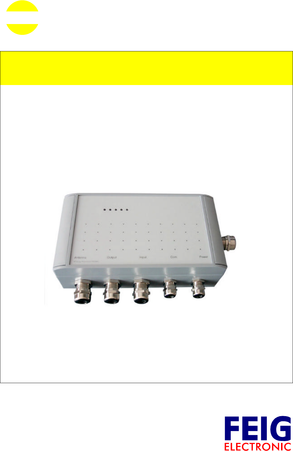
3Installation and Wiring
3.1 Installation
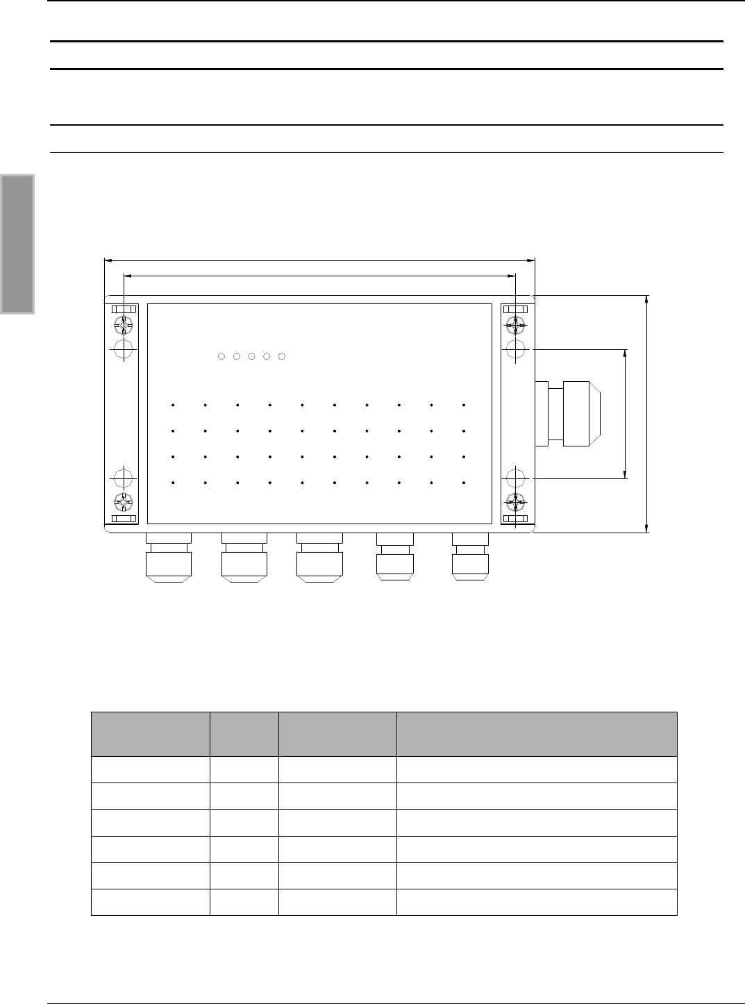
The Reader is designed for wall mount, including outdoors. Holes are provided in the housing for
wall attachment. The housing does not need to be opened for installation on a wall (see Fig. 1).
Fig. 3-1: Housing ID ISC.MR200
Cable gland Size Clamping range
[mm] Description
1M 16 4.5 – 10 Antenna cable
2M 16 4.5 – 10 Relay / Outputs
3M 16 4.5 – 10 Inputs
4M 12 3.5 – 7 Interface (serial)
5M 12 3.5 – 7 Supply voltage
6M 25 9 – 17 Ethernet Interface (model –E only)
Table 3-1: ID ISC.MR200 cable glands
200
110
182
60
6
345
21
Antenna Output Input Com Power
RFID by FEIG ELECTRONIC
OBID i-scan®Montage / Installation ID ISC.MR200
FEIG ELECTRONIC GmbH Page 11 of 30 M40400-1de-ID-B.doc
ENGLISH
3.1.1 Seal caps
The seal caps included in the scope of delivery can be used to close off unused cable fittings.
The reducing ring provided is intended for the network connection. The slotted reducer is placed
over the network cable and then fixed in place in the cable gland.
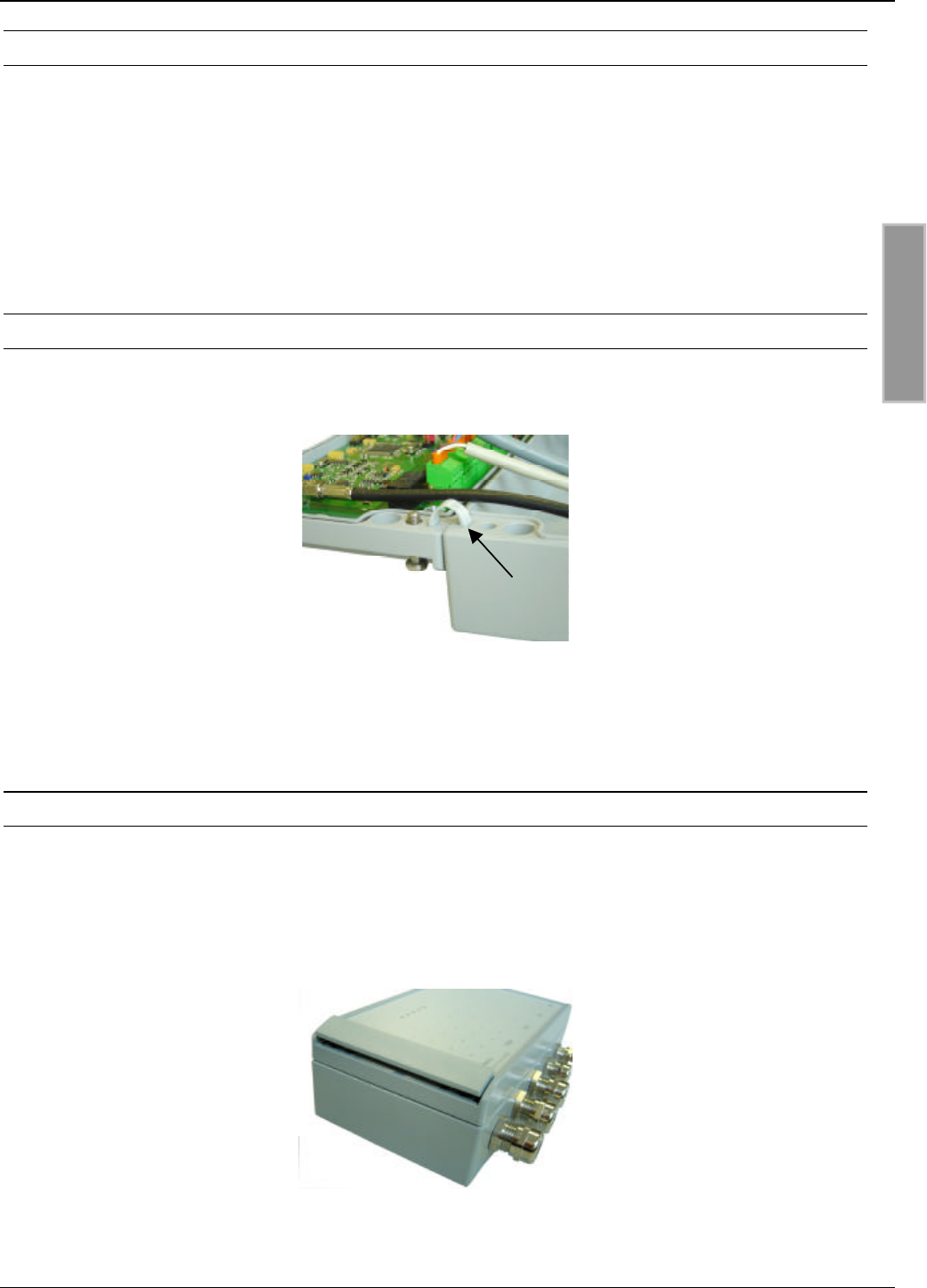
3.1.2 Cover stays
The two cover stays can be used to attach the cover to the housing. The cover stays are inserted
into the openings provided for this purpose.
Fig. 3-2: Cover stay
3.1.3 Decorative covers
The decorative covers are attached after installing the Reader.
The slot on the long side of the cover is used for disassembling the cover. Use a screwdriver to
remove the cover.
Fig. 3-3: Decorative cover
OBID i-scan®Montage / Installation ID ISC.MR200
FEIG ELECTRONIC GmbH Page 12 of 30 M40400-1de-ID-B.doc
ENGLISH
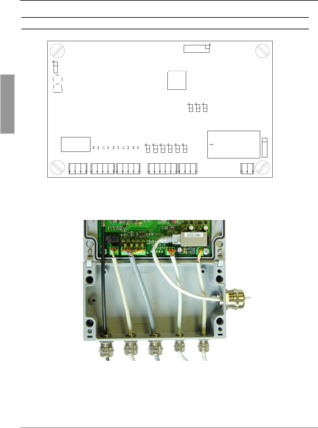
3.2 Wiring terminals
Fig. 3-4: Wiring terminals
Fig. 3-5: Maximum cable configuration (shown: ID ISC.MR200-E)
X1
X6
X7
X3
X5X4
X8 X10
X9
X2
K1 J9 J8 J7J6 J5 J4
V5 V4 V3 V2 V1
J3 J2 J1
112345 12312341234123 2
J10
OBID i-scan®Montage / Installation ID ISC.MR200
FEIG ELECTRONIC GmbH Page 13 of 30 M40400-1de-ID-B.doc
ENGLISH
3.3 Antenna connection
An SMA socket is provided on the circuit board for connecting the external antenna.
The maximum tightening torque of the SMA sockets is 0.45 Nm.
Caution:
Greater tightening torque will destroy the connector.
Terminal Description
X2 External antenna connection
(input impedance 50Ω)
Table 3-2: Connecting the external antenna
Notes:
•The input impedance of the antenna should be calibrated to a value of 50 Ω±(3 Ω∠3°).
•The optimal operating Q of the antenna should be in a range of Q
O= 20...30. To
determine the operating Q, the antenna must be supplied with a 50Ωsource, such as a
network analyzer or a frequency generator.
•When connecting the antenna be sure that the permissible limits specified by national
code with respect to RF installations are not exceeded.
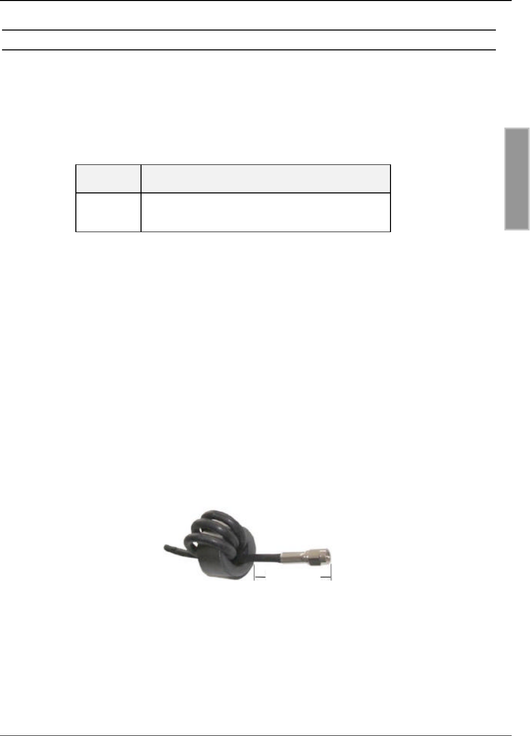
•To meet national code with respect to RF installations, each antenna feed line must be
equipped with the supplied ∅28 mm x 20 mm EMC ferrite ring core. The antenna line
must be wrapped tightly around the EMC ferrite ring core at least 4 times. The distance
between the Reader connection and the ring core should be no greater than 20 cm (see
Fig. 3.2.-1).
max. 20cm
Fig. 3-6: Antenna cable with EMC ferrite ring core
OBID i-scan®Montage / Installation ID ISC.MR200
FEIG ELECTRONIC GmbH Page 14 of 30 M40400-1de-ID-B.doc
ENGLISH
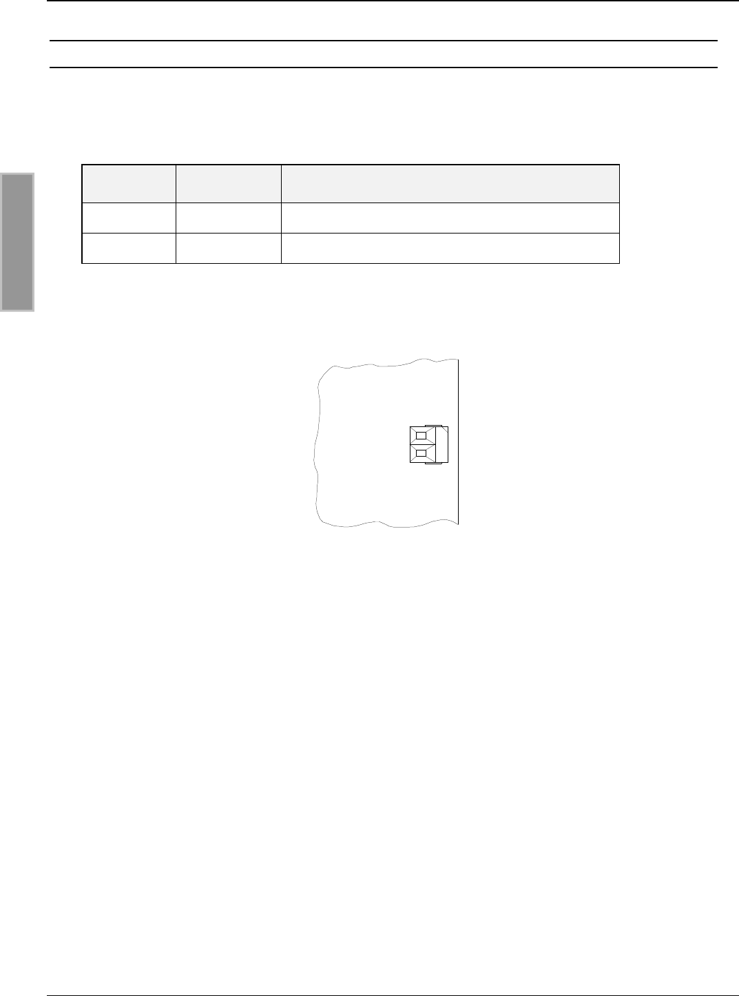
3.4 Supply voltage
Connect the 12-24 VDC supply voltage to Terminal X1.
The cable length between the power supply and the Reader module must not exceed 3 m.
Terminal Abbreviation Description
X1 / Pin 1 Vcc Vcc – supply voltage
X1 / Pin 2 GND Ground – supply voltage
Table 3-3: Supply voltage pin assignments
Fig. 3-7: Connecting the supply voltage
Note:
•Reversing the polarity of the supply voltage may destroy the unit.
GND
Vcc
X3
2
1
ID ISC.MR200

OBID i-scan®Montage / Installation ID ISC.MR200
FEIG ELECTRONIC GmbH Page 15 of 30 M40400-1de-ID-B.doc
ENGLISH
Recommended power supplies :
To make full use of the performance capability of the Reader module, a sufficiently regulated and
noise-free power supply (noise ripple = max. 150 mV) should be used. When using a switching
power supply be sure that the internal switching frequency of the power supply is less than 300
kHz.
The power supply should be a Safety Extra-Low Voltage (SELV) type with limited power. The
output power of the power supply should be at least 15 watts.
Output voltage 12 - 24 VDC
Output power ≥15 W
Ripple < 150 mVpp
Switching frequency < 300 kHz
Table 3-4: Electrical specifications for external power supply
Model Manufacturer
MPP15
AC adapter
CEAG AG / FRIWO Group
Von-Liebig-Straße 11
D- 48346 Ostbevern
Germany
Tel.: + 49 (0) 02532/ 81-158
www.friwo.de
MiniLine ML 30.100
MiniLine ML 30.102
DIN rail mount
PULS GmbH
Arabellastraße 15
D-81925 München
Germany
Tel.: +49 (0) 89 9278 0
www.puls-power.com
Table 3-5: Recommended power supplies
OBID i-scan®Montage / Installation ID ISC.MR200
FEIG ELECTRONIC GmbH Page 16 of 30 M40400-1de-ID-B.doc
ENGLISH
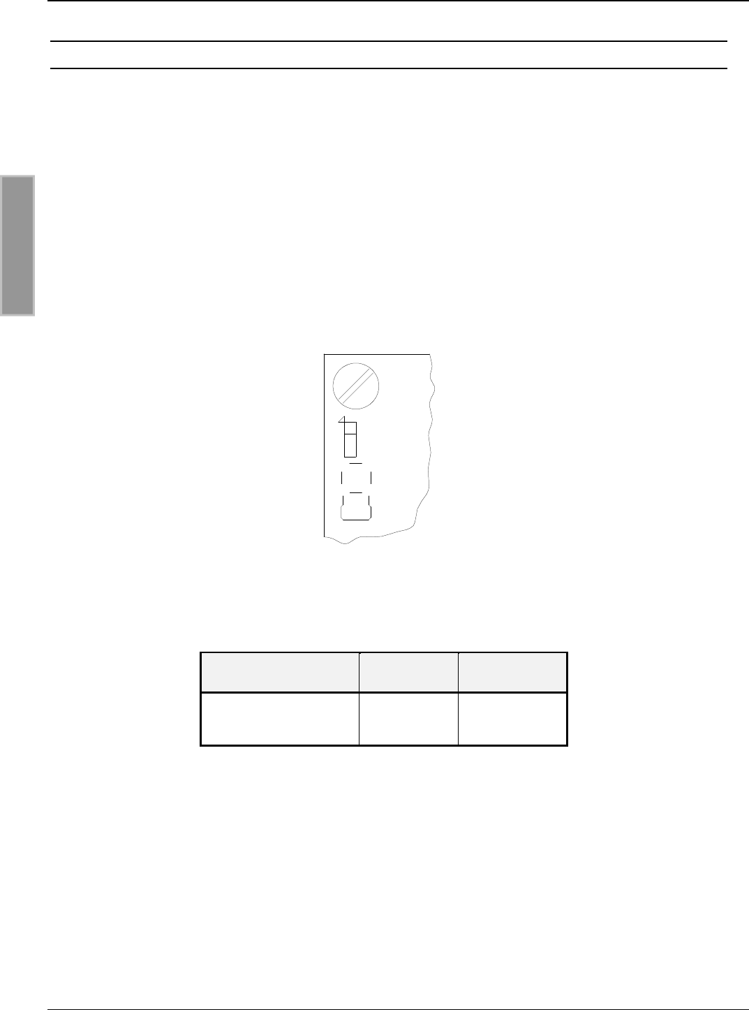
3.5 DC voltage on the RF antenna terminal X2
Jumper J10 can be used to provide DC voltage on antenna terminal X2. This DC offset is used to
power the dynamic antenna tuner (ID DAT).
Note:
•The DC voltage is intended only for power the ID ISC.DAT dynamic antenna tuner
•Connecting other antennas to this DC voltage will destroy them
Fig. 3-8: Position Jumper J10
J10 1-2 2-3
DC voltage on
antenna terminal
No
(Default) Yes
Table 3-6: Jumper J10 configuration
X2
J10
1
OBID i-scan®Montage / Installation ID ISC.MR200
FEIG ELECTRONIC GmbH Page 17 of 30 M40400-1de-ID-B.doc
ENGLISH
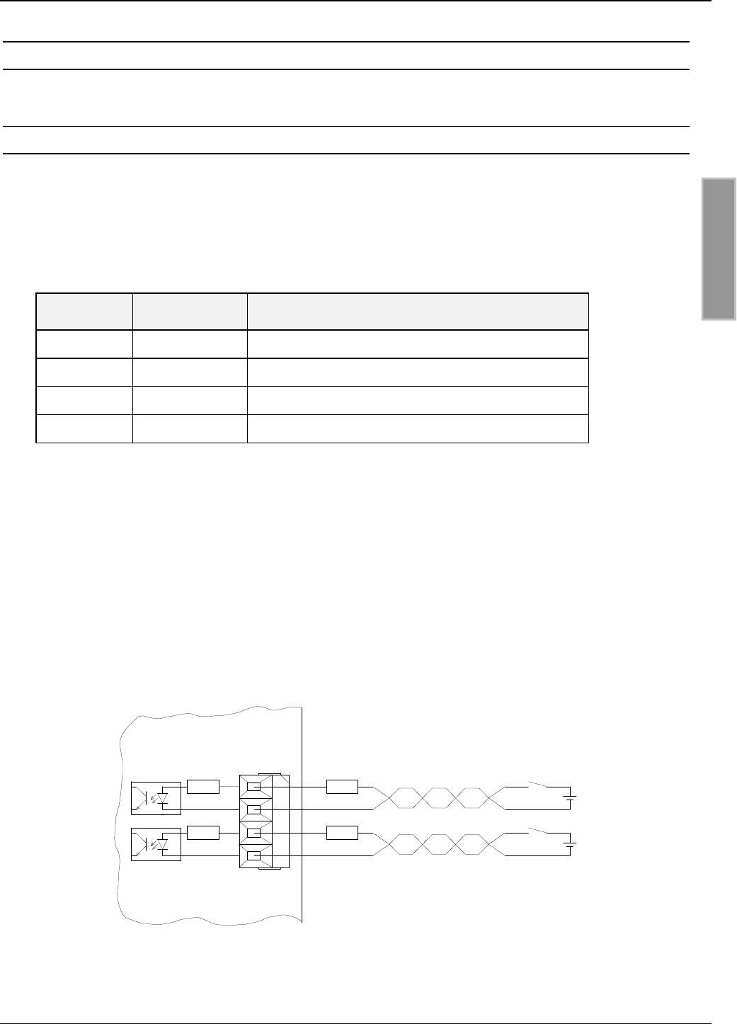
3.6 Inputs
3.6.1 Optocoupler
The optocoupler inputs in Terminal X5 are galvanically isolated from the Reader electronics and
must therefore be externally supplied. The input LEDs for the optocouplers are switch internally
with a series resistor of 500 Ω. For supply voltages of greater than 10V the input current must be
limited to max. 20 mA by an additional external series resistor (see Table 3.4-1).
Terminal Abbreviation Description
1IN1+ + Input 1
2IN1- - Input 1
3IN2+ + Input 2
4IN2- - Input 2
Table 3-7: Optocoupler input pin assignments
Notes:
•The inputs are configured for a maximum input current of 24 V DC and an input current
of maximum 20 mA.
•Reversing the polarity or overloading the inputs will destroy them.
•The Reader supply voltage must not be used to drive the inputs, since otherwise
additionally induced noise may reduce the effective reading range.
Fig. 3-9: Internal and possible external wiring of the optocoupler inputs
Uext.
Uext.
IN1-
IN2-
IN2+ ext
RRint
IN1+ Rext
Rint
X5
ID ISC.MR200
4
3
2
1

OBID i-scan®Montage / Installation ID ISC.MR200
FEIG ELECTRONIC GmbH Page 18 of 30 M40400-1de-ID-B.doc
ENGLISH
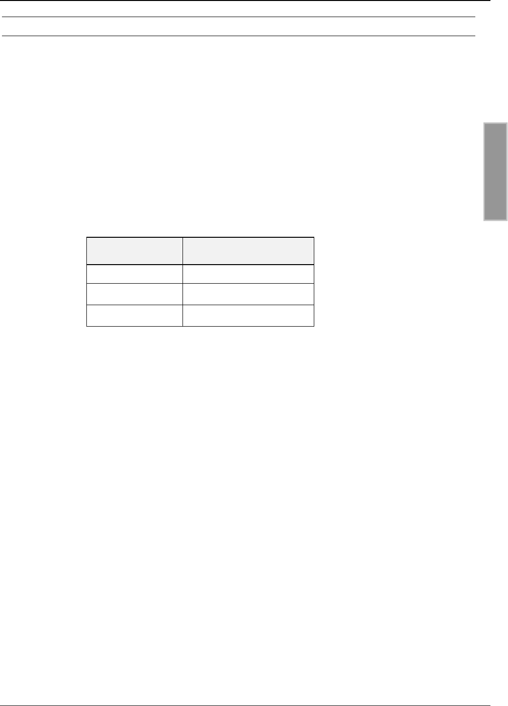
Fehler! Verweisquelle konnte nicht gefunden werden. shows the required external series
resistances at various external voltages Uext.
External voltage Uext Required external series
resistor Rext
5 V ... 10 V ---
11 V ... 15 V 270 Ω
16 V ... 20 V 560 Ω
21 V ... 24 V 820 Ω
Table 3-8: Required external series resistance Rext
OBID i-scan®Montage / Installation ID ISC.MR200
FEIG ELECTRONIC GmbH Page 19 of 30 M40400-1de-ID-B.doc
ENGLISH
3.7 Outputs
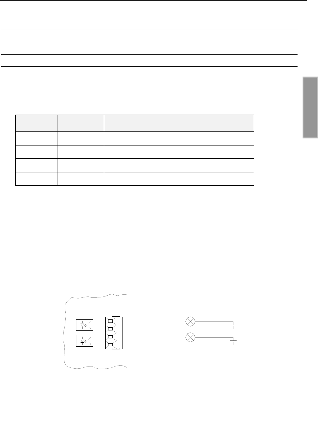
3.7.1 Optocouplers
The transistor connections of the two optocoupler outputs, collector and emitter, are galvanically
isolated from the Reader electronics and brought out with no internal circuitry to Terminal X6. The
outputs must therefore be powered with an external power supply.
Terminal Abbreviation Description
1O1-C Collector – Output 1
2O1-E Emitter – Output 1
3O2-C Collector – Output 2
4O2-E Emitter – Output 2
Table 3-9: Optocoupler output pin configuration
Notes:
•The outputs are configured for max. 24 V DC / 30 mA.
•Reversing the polarity or overloading the outputs will destroy them.
•The outputs are intended for switching resistive loads only.
Fig. 3-10:: Internal and possible external wiring of the optocoupler outputs
O1-E
O2-E
O2-C
O1-C
X3
4
3
2
1
ID ISC.MR200
Uext.
Uext.

OBID i-scan®Montage / Installation ID ISC.MR200
FEIG ELECTRONIC GmbH Page 20 of 30 M40400-1de-ID-B.doc
ENGLISH
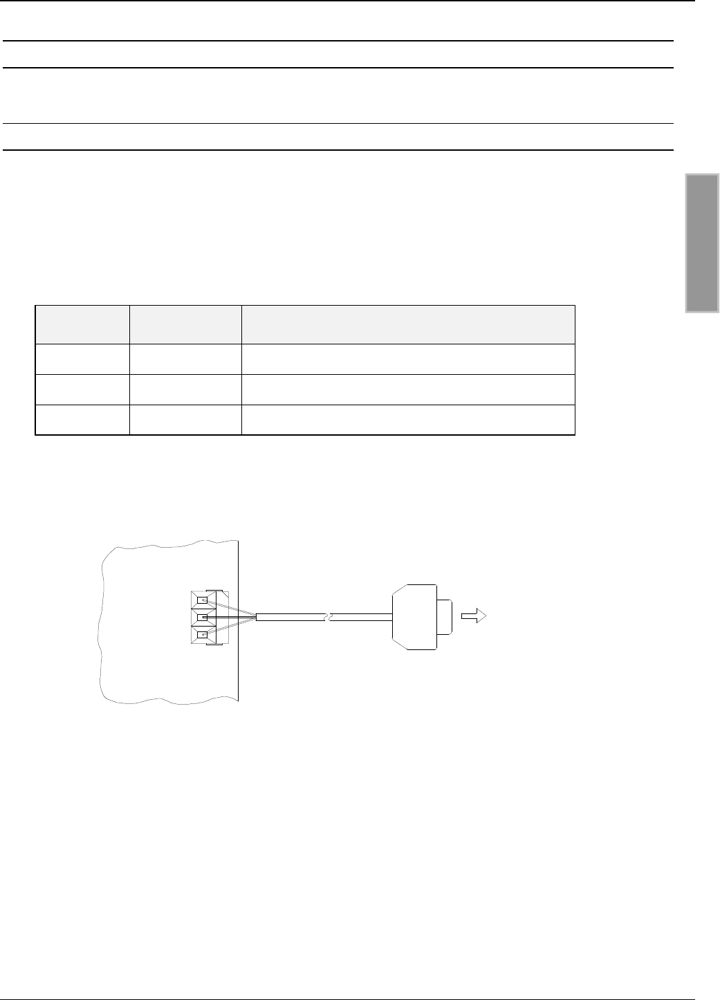
3.7.2 Relay
A changeover relay is provided.
Terminal Abbreviation Description
1COM Working contact
2NC Normally closed
3NO Normally open
Table 3-10: Relay output pinouts
Notes:
•The relay outputs are configured for max. 24 V DC / 2 A.
•The relay outputs are intended for switching resistive loads only. If an inductive load is
used, the relay contacts must be protected by means of an external protection circuit.
Fig. 3-11: Internal and possible external wiring of the relay output
ID ISC.MR200
COM
NO
NC ext.
U
X4
3
2
1
OBID i-scan®Montage / Installation ID ISC.MR200
FEIG ELECTRONIC GmbH Page 21 of 30 M40400-1de-ID-B.doc
ENGLISH
3.8 Interfaces
3.8.1 RS232 interface
The RS232 interface is connected at Terminal X6.
The transmission parameters are configured using software protocol.
Pin assignments X6 (RS232 interface):
Terminal Abbreviation Description
1GND RS232 – GND
2RxD RS232 - RxD
3TxD RS232 - TxD
Table 3-11: RS232 interface pin assignments
Fig. 3-12: Wiring example for connecting the RS232 interface
PC
<−>
<−>
<−>
9-pol. DUB-D-Buchse
TxD
RxD
GND
ID ISC.MR200
X6
3
2
1
X6 / 1 Pin 5
Pin 3
Pin 2
X6 / 2
X6 / 1
OBID i-scan®Montage / Installation ID ISC.MR200
FEIG ELECTRONIC GmbH Page 22 of 30 M40400-1de-ID-B.doc
ENGLISH
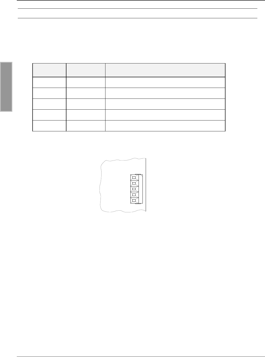
3.8.1.1 Wiring assignments
The RS485 interface is connected at Terminal X7.
Pin assignments X7 (RS485 interface):
Terminal Abbreviation Description
1GND RS485 – (B +) RS485 – GND
2A- RS485 – (A -)
3B+ RS485 – (B +)
4Y- n.c.
5Z+ n.c.
Table 3-12: RS485 interface pin assignments
Fig. 3-13: Wiring the RSR485 interface
RS485 - (A-)
nc
RS485 - (B+)
RS485 - GND
X7
nc 5
4
3
2
1
ID ISC.MR200
OBID i-scan®Montage / Installation ID ISC.MR200
FEIG ELECTRONIC GmbH Page 23 of 30 M40400-1de-ID-B.doc
ENGLISH
3.8.2 Ethernet interface(ID ISC.MR200-E)
The Reader has an integrated 10/100Tbase network interface with RJ-45 connection. Terminal X8
serves as the Ethernet port.
Cat 5 cable should be used for structured cabling. This ensures reliable operation at 10Mbps or
100Mbps.
Pin assignments X8 (network interface):
Terminal Abbreviation Description
1TX+ Transmit Data +
2TX- Transmit Data -
3RX+ Receive Data +
4VETH+ n.c.
5VETH+ n.c.
6RX- Receive Data -
7VETH- n.c.
8VETH- n.c.
Table 3-13: Ethernet interface pin assignments

OBID i-scan®Montage / Installation ID ISC.MR200
FEIG ELECTRONIC GmbH Page 24 of 30 M40400-1de-ID-B.doc
ENGLISH
4Operating and Display Elements
4.1 LED´s
Fehler! Verweisquelle konnte nicht gefunden werden. shows the configuration of the LED’s.
Abbreviation Description
LED V1 (green) "RUN-LED"
-Indicates proper running of the internal Reader software
-Flashing frequency approx. 1 Hz
LED V2 (blue) Diagnostic 1: RF communication / EEPROM status
-Short flashing indicates errorless communication with a
transponder on the RF interface
-Flashes alternately with V1 after the reset following a software
update
-Flashes alternately with V1 if an error in reading the
parameters occurred following a reset
LED V3 (yellow Diagnostic 2: Host communication
-Short flashing indicates a protocol is being sent to the host.
LED V4 (yellow) Diagnostic 3: for future applications
LED V5 (red) Diagnostic 4: Reader initializing / RF error
-Comes on during Reader initializing following power-on or after
a reset.
-Comes on when there is an error in the RF section of the
Reader.
The error type can be read via software using the Reader
Diagnostic command [0x6E].
Table 4-1: LED configuration

OBID i-scan®Montage / Installation ID ISC.MR200
FEIG ELECTRONIC GmbH Page 25 of 30 M40400-1de-ID-B.doc
ENGLISH
5Startup
5.1 Port configuration
Both Reader ports can be used for communication. The Reader automatically detects which port is
being used for communication. The RS232 port is used as a service port and thus has higher
priority. If communication takes place on the RS232 port, the other port (RS485 for ID ISC.MR200-
A and network port for ID ISC.MR-200-E) is disabled for a time of 10 seconds. This lockout can be
cancelled by means of a reset.
Fehler! Verweisquelle konnte nicht gefunden werden. shows the standard configuration of the
RS232 port.
Baud rate 38400
Frame 8E1
Table 5-1: Standard configuration of the RS232 port
OBID i-scan®Montage / Installation ID ISC.MR200
FEIG ELECTRONIC GmbH Page 26 of 30 M40400-1de-ID-B.doc
ENGLISH
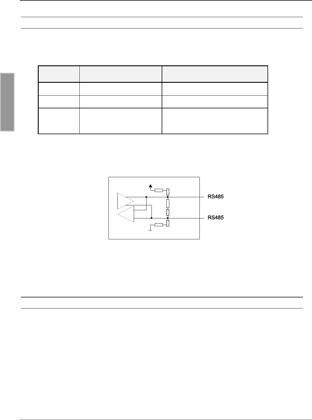
5.1.1 RS485 (ID ISC.MR200-A)
In the case of the RS485 interface, any necessary termination resistors can be enabled by
inserting jumpers J4, J5 and J6.
Jumper In Out
J4 Pull-Up on RS485 - B without Pull-Up on RS485 - B
J5 Pull-Down on RS485 - A without Pull-Down on RS485 – A
J6 Termination resistor
RS485 - A ⇔RS485 - B
without termination resistor
RS485 - A ⇔RS485 - B
Table 5-2: RS485 termination resistors
Fig. 5-1: RS485 port jumpers
5.1.1.1 Setting RS485 addresses for bus operation
The Reader allows you to assign the required bus address via software.
Addresses are assigned by the host computer. The software is used to assign addresses between
“0” and “254”.
Note:
Since all Readers are factory set with address 0, they must be connected and configured in
succession.
J4
J6
J5
500 Ohm
500 Ohm
100 Ohm
OBID i-scan®Montage / Installation ID ISC.MR200
FEIG ELECTRONIC GmbH Page 27 of 30 M40400-1de-ID-B.doc
ENGLISH
5.1.2 Ethernet Interface(ID ISC.MR200-E)
The prerequisite for using TCP/IP protocol is that each device on the network have a unique IP
address. All Readers have been assigned a factory default IP address.
Note:
The Readers must be connected to the network and configured in succession.
Fehler! Verweisquelle konnte nicht gefunden werden. shows the standard configuration of the
network connection.
Network Address
IP address 192.168.10.10
Subnet mask 255.255.255.0
Port 10001
Table 5-3: Standard configuration of the network connection

OBID i-scan®Montage / Installation ID ISC.MR200
FEIG ELECTRONIC GmbH Page 28 of 30 M40400-1de-ID-B.doc
ENGLISH
6Technical Specifications
Mechanical Data
•Enclosure Die-case aluminum, powder-coated,
lockable hinged cover
•Dimensions ( W x H x D ) 200 x 110 x 60 mm
•Weight 1.0 kg
•Enclosure rating IP 54
•Color RAL 7040 (similar to window grey)
Electrical Data
•Supply voltage 12 VDC to 24VDC ±5 %
Noise Ripple : max. 150 mV
•Power consumption max. 13 VA
•Operating frequency 13.56 MHz
•Transmitting power 1 W / 1.75W ± 1 dB
•Degree of modulation 20% ± 3% absolute
•Antenna connection 1 x SMA socket (50Ω)
•Outputs:
- 2 optocoupler
- 1 relay ( 1 x changeover)
24 V DC / 30 mA (galvanically isolated)
24 V DC / 2 A
•Inputs
– 2 optocoupler max. 24 V DC/ 20 mA
•Interfaces
- ID ISC.MR200-A
- ID ISC.MR200-E
RS232 and RS485
RS232 and Ethernet

OBID i-scan®Montage / Installation ID ISC.MR200
FEIG ELECTRONIC GmbH Page 29 of 30 M40400-1de-ID-B.doc
ENGLISH
Functional Properties
•EEPROM (for parameters) 10,000 write cycles
•FLASH Software can be updated on interface
•Supported transponders •ISO15693 (I•Code SLI, Tag-it HFI, my-d,
STM LRI512)
•I•Code MID and EPC-Transponder
•Address setting for interface
(ID ISC.MR200-A only) - Software (up to 254 addresses)
•Optical indicators 5 LED´s for diagnosing the operating status
Ambient Conditions
•Temperature range
- Operating
- Storage
-20°C to +60°C
-25°C to +85°C
•Vibration EN60068-2-6
10 Hz to 150 Hz :0.075 mm / 1 g
•Shock EN60068-2-27
Acceleration :30 g
Applicable Standards
•RF approval
- Europe
- USA
EN 300 330
FCC 47 CFR Part 15
•EMC EN 301 489
•Safety
- Low Voltage
- Human Exposure
EN 60950
EN 50364

OBID i-scan®Montage / Installation ID ISC.MR200
FEIG ELECTRONIC GmbH Page 30 of 30 M40400-1de-ID-B.doc
ENGLISH
6.1 Approval
6.1.1 Europe (CE)
When properly used, the RF system is in conformance with the essential requirements of Article 3
and the other relevant provisions of the R&TTE Directive 1995/5/EC of March 99.
Equipment Classification according to ETSI EN 300 330 and ETSI EN 301 489
6.1.2 USA (FCC)
FCC ID: PJMMR200
This device complies with Part 15 of the FCC Rules. Operation is subject to the following
two conditions:
(1) this device may not cause harmful interference, and
(2) this device must accept any interference received, including interference that may
cause undesired operation.
Unauthorized modifications may void the authority granted under Federal communica-
tions Commission Rules permitting the operation of this device.
Warning: Changes or modification made to this equipment not expressly approved by
FEIG ELECTRONIC GmbH may void the FCC authorization to operate this equipment.