Feig Electronic MR200 Inductive Reader User Manual Antenna 1
Feig Electronic GmbH Inductive Reader Users Manual Antenna 1
Contents
- 1. Users Manual
- 2. Users Manual Antenna 1
- 3. Users Manual Antenna 2
Users Manual Antenna 1

MONTAGE
INSTALLATION
final
public
2002-06-05
M01001-2de-ID-B.DOC
OBI
D
®
i-scan
ID ISC.ANT300/300-A
(deutsch / english)

OBID®Montage ID ISC.ANT300/300-A
FEIG ELECTRONIC GmbH Seite 3 von 43 M01001-2de-ID-B.DOC
D E U T S C H
Lieferumfang:
• 1 Stück Antenne ID ISC.ANT300/300-A inklusive Anschlußkabel
• Montageanleitung
Hinweis
Copyright 2002 by
FEIG ELECTRONIC GmbH
Lange Straße 4
D-35781 Weilburg-Waldhausen
Tel.: +49 6471 3109-0
http://www.feig.de
Ausgabe: wm/02/06/04 - m01001-2de-id-b.doc
Alle früheren Ausgaben verlieren mit dieser Ausgabe ihre Gültigkeit.
Die Angaben in diesem Dokument können ohne vorherige Ankündigung geändert werden.
Weitergabe sowie Vervielfältigung dieses Dokuments, Verwertung und Mitteilung ihres Inhalts sind nicht
gestattet, soweit nicht ausdrücklich zugestanden. Zuwiderhandlung verpflichtet zu Schadenersatz. Alle
Rechte für den Fall der Patenterteilung oder Gebrauchsmuster-Eintragung vorbehalten.
Die Zusammenstellung der Informationen in diesem Dokument erfolgt nach bestem Wissen und Gewissen.
FEIG ELECTRONIC GmbH übernimmt keine Gewährleistung für die Richtigkeit und Vollständigkeit der An-
gaben in diesem Dokument. Insbesondere kann FEIG ELECTRONIC GmbH nicht für Folgeschäden auf
Grund fehlerhafter oder unvollständiger Angaben haftbar gemacht werden. Da sich Fehler, trotz aller Bemü-
hungen nie vollständig vermeiden lassen, sind wir für Hinweise jederzeit dankbar.
Die in diesem Dokument gemachten Installationsempfehlungen gehen von günstigsten Rahmenbedingun-
gen aus. FEIG ELECTRONIC GmbH übernimmt keine Gewähr für die einwandfreie Funktion in systemfrem-
den Umgebungen.
FEIG ELECTRONIC GmbH übernimmt keine Gewährleistung dafür, dass die in diesem Dokument enthal-
tenden Informationen frei von fremden Schutzrechten sind. FEIG ELECTRONIC GmbH erteilt mit diesem
Dokument keine Lizenzen auf eigene oder fremde Patente oder andere Schutzrechte.
OBID® ist ein eingetragenes Warenzeichen der FEIG ELECTRONIC GmbH
Allgemeine Hinweise zu diesem Handbuch
• Das Zeichen „)“ weist auf Erweiterungen bzw. Änderungen gegenüber der Vorgängerversion
hin.
• Die verwendeten Zahlenformate sind
0...9: für dezimale Zahlenwerte und
0x00...0xFF: für hexadezimale Zahlenwerte,
b0...1 für binäre Zahlenwerte.

OBID®Montage ID ISC.ANT300/300-A
FEIG ELECTRONIC GmbH Seite 4 von 43 M01001-2de-ID-B.DOC
D E U T S C H
Inhalt
1. Sicherheits- und Warnhinweise - vor Inbetriebnahme unbedingt lesen 5
2. Das Funktionsprinzip des OBID® i-scan-Systems 6
3. Leistungsmerkmale der Antenne ID ISC.ANT300/300-A 6
4. Montage und Anschluß 7
5. Inbetriebnahme 10
5.1. Funk-Regularien im EU-Raum und der USA...................................................................10
5.2. Der Einfluß der Sendeleistung des Readers auf die Lesereichweite ...........................11
5.3. Der Einfluß von Metall auf die Reichweite ......................................................................12
5.4. Der Einfluß der Noise Level auf die Reichweite der Antenne .......................................13
5.5. Das Messen des Stehwellenverhältnisses VSWR..........................................................14
5.6. Der Abgleich der Antenne ................................................................................................15
6. Der Verlauf der magnetischen Feldlinien der Antenne 18
7. Technische Daten ID ISC.ANT300/300 19
8. Anhang Hilfreiche Werkzeuge für den Aufbau und Test der Antennen 21
8.1. Gerätevorschläge und mögliche Bezugsquellen : ...................................................22

OBID®Montage ID ISC.ANT300/300-A
FEIG ELECTRONIC GmbH Seite 5 von 43 M01001-2de-ID-B.DOC
D E U T S C H
1. Sicherheits- und Warnhinweise - vor Inbetriebnahme unbedingt lesen
• Das Gerät darf nur für den vom Hersteller vorgesehenen Zweck verwendet werden.
• Die Bedienungsanleitung ist zugriffsfähig aufzubewahren und jedem Benutzer auszuhändigen.
• Unzulässige Veränderungen und die Verwendung von Ersatzteilen und Zusatzeinrichtungen,
die nicht vom Hersteller des Gerätes verkauft oder empfohlen werden, können Brände, elektri-
sche Schläge und Verletzungen verursachen. Solche Maßnahmen führen daher zu einem
Ausschluß der Haftung, und der Hersteller übernimmt keine Gewährleistung.
• Für das Gerät gelten die Gewährleistungsbestimmungen des Herstellers in der zum Zeitpunkt
des Kaufs gültigen Fassung. Für eine ungeeignete, falsche manuelle oder automatische Ein-
stellung von Parametern für ein Gerät bzw. ungeeignete Verwendung eines Gerätes wird kei-
ne Haftung übernommen.
• Reparaturen dürfen nur vom Hersteller durchgeführt werden.
• Anschluß-, Inbetriebnahme- Wartungs- und sonstige Arbeiten am Gerät dürfen nur von Elekt-
rofachkräften mit einschlägiger Ausbildung erfolgen.
• Vor dem Öffnen des Gerätes ist stets die Versorgungsspannung abzuschalten und durch
Nachmessen sicherzustellen, daß das Gerät spannungslos ist. Das Verlöschen einer Be-
triebsanzeige ist kein Indikator dafür, daß das Gerät vom Netz getrennt und spannungslos ist.
• Alle Arbeiten am Gerät und dessen Aufstellung müssen in Übereinstimmung mit den nationa-
len elektrischen Bestimmungen und den örtlichen Vorschriften durchgeführt werden.
• Beim Arbeiten an den Geräten müssen die jeweils gültigen Sicherheitsvorschriften beachtet
werden.
• Beim Arbeiten am geöffneten Gerät ist zu beachten, daß Spannungen bis zu 1000V an den
Bauteilen anliegen können.

OBID®Montage ID ISC.ANT300/300-A
FEIG ELECTRONIC GmbH Seite 6 von 43 M01001-2de-ID-B.DOC
D E U T S C H
2. Das Funktionsprinzip des OBID® i-scan-Systems
Das Identifikationssystem OBID® i-scan ist ein induktives Übertragungssystem zur berührungslo-
sen Identifikation (ID) von bewegten Objekten. Mit den Komponenten des Schreib- / Lesesystems
ist ein Beschreiben und Lesen von passiven Datenträgern (Transponter) mit einer Arbeitsfrequenz
von 13.56 MHz, sogenannten „Smart Label“ möglich. Es besteht aus den Komponenten Reader
ID ISC.LR200, einer oder mehreren Antennen und einem oder mehreren Smart Labeln als Spei-
chermedium für die Daten.
Diese Smart Label sind i.d.R. Papieretiketten, in denen ein hauchdünner Transponder eingefaßt ist
und die somit mit RFID Schreib-/Lesegeräten kommunizieren können.
Gelangt ein Smart Label in das lokale Magnetfeld der Antenne, wird er mit Energie versorgt und
kann gelesen und beschrieben werden. Die empfangenen Daten werden von der gleichen Antenne
des Readers empfangen, die auch das Magnetfeld erzeugt und die Daten zum Datenträger sendet.
Das Magnetfeld und die gesendeten und empfangenen Daten vom Datenträger können nahezu
alle nichtleitenden Materialien durchdringen, so daß auch ein verdecktes Schreiben und Lesen
möglich ist.
Die Anticollision-Funktion des Readers ermöglicht das gleichzeitige Lesen von bis zu 50 Smart
Label pro Sekunde.
3. Leistungsmerkmale der Antenne ID ISC.ANT300/300-A
Die Antenne ID ISC.ANT300/300-A ist eine Single Loop Antenne mit manuell eingestellbarer Ab-
gleichelektronik und wurde als eine Sende- und Empfangsantenne für den Reader ID ISC.LR200
optimiert. Bei einer am Reader eingestellten Sendeleistung von 4 W ist eine Lesereichweite von
maximal 55 cm möglich. Ebenfalls ist ein Betrieb an anderen Readern mit einer Sendefrequenz
von 13,56 MHz und der Ausgangsimpedanz von 50 Ω möglich.
Die Antenne wurde im Werk an einer Holzplatte auf die Impedanz von 50 Ω abgestimmt. Nach der
Montage in anderen Umgebungsbedingungen kann die Antenne mit Hilfe von Steckbrücken (Jum-
pern) neu abgestimmt werden.
Die Antenne kann sowohl für die Güter- als auch in der Personenerkennung verwendet werden.
Die Vorzugsrichtung eines Smart Label ist parallel zur Antennenfläche. Die maximale Reichweite
wird über der Mitte der Antennenfläche erreicht.

OBID®Montage ID ISC.ANT300/300-A
FEIG ELECTRONIC GmbH Seite 7 von 43 M01001-2de-ID-B.DOC
D E U T S C H
322±2
267±1
40+0,5
-1,0 267±1
322±2
337±2
38±0,5
28±0,5
13 0,0
-1,0
5,6±0,2
4. Montage und Anschluß
Die Antenne ist für die Montage an Halterungen aus nicht leitende Materialien (z.B. Kunststoff oder
Holz) sowohl für den Innen- wie auch den Außenbereich konzipiert. Zur Montage befinden sich im
Innenbereich der Antenne 4 Bohrungen (d=5,6 mm) im Abstand von 268 mm zur Befestigung. Zur
Montage empfehlen wir eine 5 mm Holzschraube (DIN 96) oder eine Maschinenschraube
(DIN 7985) mit einem Kopfdurchmesser von mindestens 10 mm bis maximal 12 mm. Das maxi-
male Anzugsmoment für freidrehende Schrauben beträgt 2,0 Nm.
Reichen die vorhanden Bohrungen nicht aus, können innerhalb des schraffierten Bereichs, weitere
Löcher (d=5,6 mm) gebohrt werden.
Die Antenne muß einen Mindestabstand von 10 cm von eventuellen Metallteilen haben! Ab
50 cm Abstand zu Metallteilen muß mit Einbußen in der Lesereichweite gerechnet werden. Dies
kann durch nachgleichen der Antenne verringert werden Siehe Seite 15 5.6. Der Abgleich der An-
tenne.
Bild 1: Montagezeichnung ID ISC.ANT300/300-A
Alle Maße in mm
Zum Abgleichen der Antenne muß der Deckel über der Antennenöffnung entfernt werden. Das
Anzugsmoment der Deckelschrauben beträgt minimal 0,2 Nm bis maximal 0,25 Nm.
Antennenöffnung
(Deckel)
OBID®Montage ID ISC.ANT300/300-A
FEIG ELECTRONIC GmbH Seite 8 von 43 M01001-2de-ID-B.DOC
D E U T S C H
Die Antenne wird mit Hilfe des Anschlußkabels und dem SMA- Stecker direkt an den Reader an-
geschlossen. Um Störungen in industriellen Umgebungen zu unterdrücken empfehlen wir zusätz-
lich das Gerät ID ISC.ANT.T Transformer zwischen Reader und Antenne zu schalten.
Bild 2: Schaltskizze Reader mit Transformer und Basisantenne
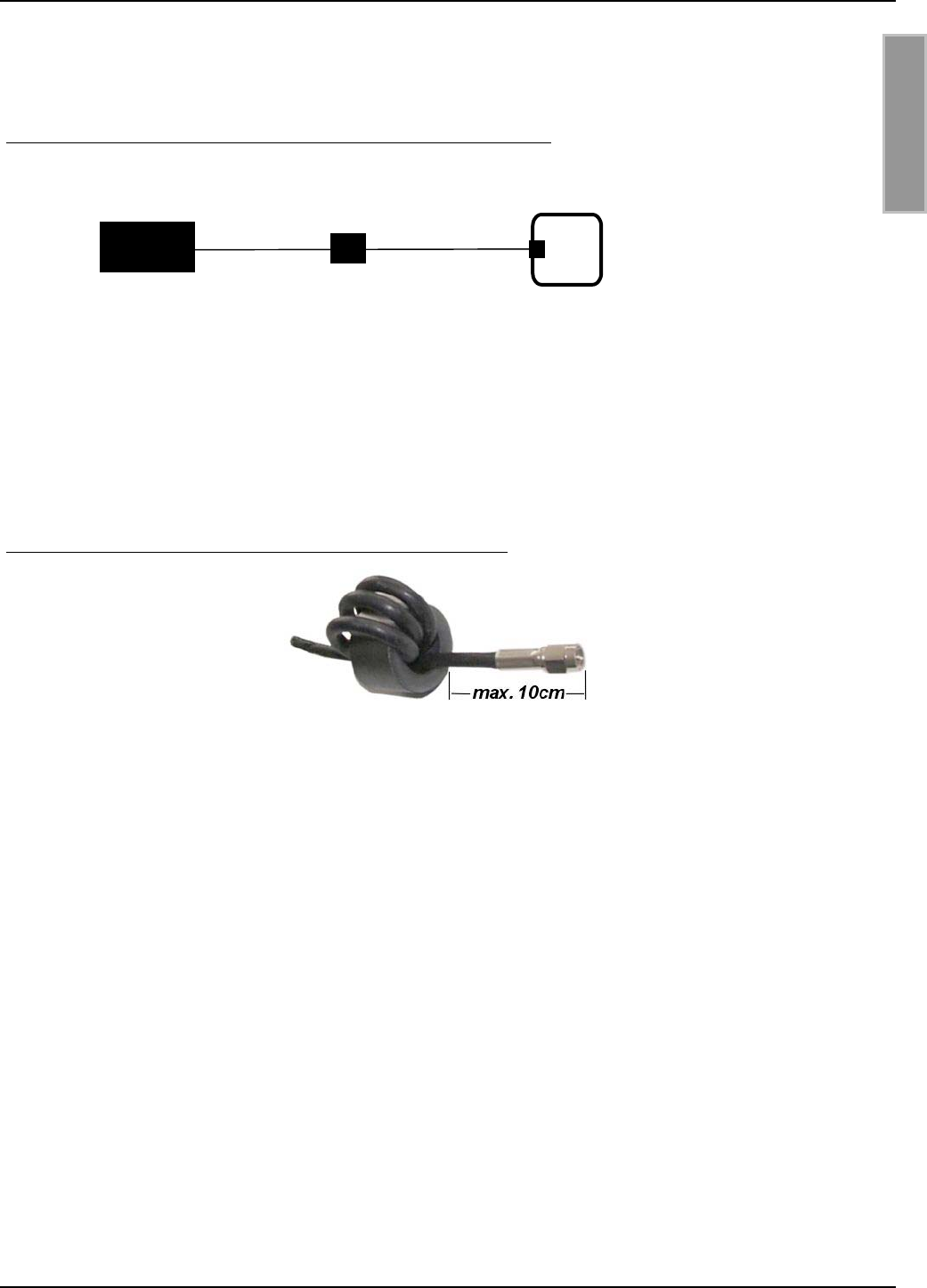
Um mögliche Störungen zu unterdrücken, werden dem Reader ID ISC.LR200 zwei Ringkerne bei-
gelegt. Einer dieser Ringkerne sollten nach Möglichkeit in das Antennenanschlußkabel eingebaut
werden. Dafür ist das Koaxial - Kabel mindestens vier mal, eng anliegend durch den EMV - Ring-
kern zu schleifen. Der Abstand zwischen Readeranschluß und Ringkern sollte dabei maximal 10
cm betragen.
Bild 3: Montage des Ringkerns auf der Antennenzuleitung
Reade
r
ID ISC.ANT.T-A
ID ISC.ANT300/300-A

OBID®Montage ID ISC.ANT300/300-A
FEIG ELECTRONIC GmbH Seite 9 von 43 M01001-2de-ID-B.DOC
D E U T S C H
Die folgenden Empfehlungen sollten zusätzlich beachtet werden:
• Bis zu einem Abstand von 50 cm sollte das Antennenkabel immer senkrecht von der Antenne
weg geführt und komplett fest verlegt werden.
• Um optimale Lesereichweiten zu erzielen sollte das Antennenanschlußkabel nicht verkürzt o-
der verlängert werden. Ist eine Verlängerung zwingend erforderlich, so kann dies mit dem 50 Ω
Kabel ID ISC.ANT.EC in der Länge 2
λ
(halbe Wellenlänge bei 13,56 MHz, RG58=7,20 m)
durchgeführt werden. Dabei ist mit geringen Empfindlichkeitsverlusten zu rechnen (ca.2 cm
Lesereichweite/Verlängerung).
• Das Antennenkabel muß einen Mindestabstand von 30 cm zu parallel geführten , stromführen-
den Leitungen haben.
Nach der Montage kann die korrekte Funktion der Antenne mit Hilfe des Readers und eines Smart
Labels geprüft werden. Bei einer am Reader eingestellten Sendeleistung von 4 W und einer Label-
größe von 75 mm x 46 mm (ISO-Kartengröße) sollte die Lesereichweite in der Mitte der Antenne
bei ca. 50 cm – 55 cm liegen.
Andernfalls sollten folgende Punkte überprüft werden:
• Wurde die Antenne in der Nähe von Metall installiert
• Wie hoch ist der Unterschied zwischen Umax-Umin der Noise Level. Die Differenz der Noise
Level sollte kleiner gleich 20 mV sein.
• Stimmt die Anpassung der Antenne an die Impedanz von 50 Ω. Dies kann mit Hilfe eines SWR
– Meters überprüft werden. Siehe Seite 14 5.5. Das Messen des Stehwellenverhältnisses
VSWR

OBID®Montage ID ISC.ANT300/300-A
FEIG ELECTRONIC GmbH Seite 10 von 43 M01001-2de-ID-B.DOC
D E U T S C H
5. Inbetriebnahme
5.1. Funk-Regularien im EU-Raum und der USA
Die Gestaltung und Sendeleistung der Antennen werden im wesentlichen durch die Länderspezifi-
schen Funk - Vorschriften beeinflußt. Für den gesamten EU-Raum gelten einheitliche Grenzwerte
nach EN 300 330. In Nord Amerika wird dies durch die FCC Part 15 geregelt.
Der für die Antennen wichtigste Grenzwert die maximal zulässige magnetische Feldstärke bei
13.56 MHz im Abstand von 10 m beträgt im EU-Raum : 42dBµA/m und in den USA 38dBµA/m.
Da die Zulassungsvorschrift FCC Part 15 in den USA einen Abstand von 50 dB zwischen Träger
und den Seitenbändern vorschreibt, darf der Reader in den USA nur in der ASK 1 aus 256 Kodie-
rung (Amplituden Modulation) betrieben werden.
In einer nicht leitenden magnetisch neutralen Umgebung in Verbindung mit dem Reader
ID ISC.LR200 kann die Antenne in EU – Raum mit maximal 4 W in den USA mit maximal 1,5 W
betrieben werden. Bei größeren oder kleineren Grenzwerten ist die Sendeleistung des Readers
entsprechend anzupassen oder die magnetische Abstrahlung durch eine Abschirmung der Anten-
ne zu verringern.
Bei der Inbetriebnahme der Antennen ist vom Systemintegrator und Inbetriebnehmer darauf zu
achten, daß die vorgeschriebenen Montagehinweise beachtet, die notwendigen Reader Einstel-
lungen durchgeführt und zulässigen Grenzwerte der nationalen Funk Vorschriften nicht über-
schritten werden.
Weiterhin ist der Reader wie folgt zu konfigurieren:
Parameter Europa USA
Allgemein
RF-Power – CFG 3 4 W 1,5 W
ISO15693 Label
Downlink RF Modulation – CFG
8 / ISO-MODE / MOD
10 % 10%
Downlink RF Data coding –
CFG 8 / ISO-MODE / FAST
Fast (1/4) or Normal (1/256) Normal (1/256)
Timeslots - CFG 8 / ISO-MODE
/ NO-TS
16 Timeslots 16 Timeslots
Inverntory Comand Option –
CFG 8 / ISO-CMD-OPTION /
BREAK
Complete Timeslot length at
„NO TAG“
Complete Timeslot length at
„NO TAG“
I-Code 1
Downlink RF Data coding –
CFG 8 / ICODE-MODE / FAST
Fast Mode (1/1) oder Normal
Mode (1/256)
- Normal Mode (1/256)
OBID®Montage ID ISC.ANT300/300-A
FEIG ELECTRONIC GmbH Seite 11 von 43 M01001-2de-ID-B.DOC
D E U T S C H
5.2. Der Einfluß der Sendeleistung des Readers auf die Lesereichweite
Die Reichweite einer Antenne ist abhängig von der Antenne selbst, dem Reader, dem Smart Label
und der eingestellten Sendeleistung des Readers. Da das Smart Label seine Energie aus dem von
der Antenne erzeugten magnetischen Feld bezieht und die Feldstärke mit dem Abstand zwischen
Reader und Antenne stark abnimmt, hat die abgestrahlte Sendeleistung bei gegebener Antenne
eine starken Einfluß auf die Reichweite.
Bild 4: Die Lesereichweite* der Antenne ID ISC.ANT300/300-A in Abhängigkeit der Sendeleistung
*Label 46 x 75 mm2, über der Antennen Mitte, Empfindlichkeit / Minimale Feldstärke Hmin=85mA/m
rms, parallele Ausrichtung des Labels zur Antenne.
Eine Sendeleistung über 8 W kann in Abhängigkeit der Umgebungstemperatur zur übermäßigen
Erwärmung der Antenne und somit zur Zerstörung der Antenne führen.
30
35
40
45
50
55
60
65
70
012345678910
Sendeleistung in W
Reichweite in cm
OBID®Montage ID ISC.ANT300/300-A
FEIG ELECTRONIC GmbH Seite 12 von 43 M01001-2de-ID-B.DOC
D E U T S C H
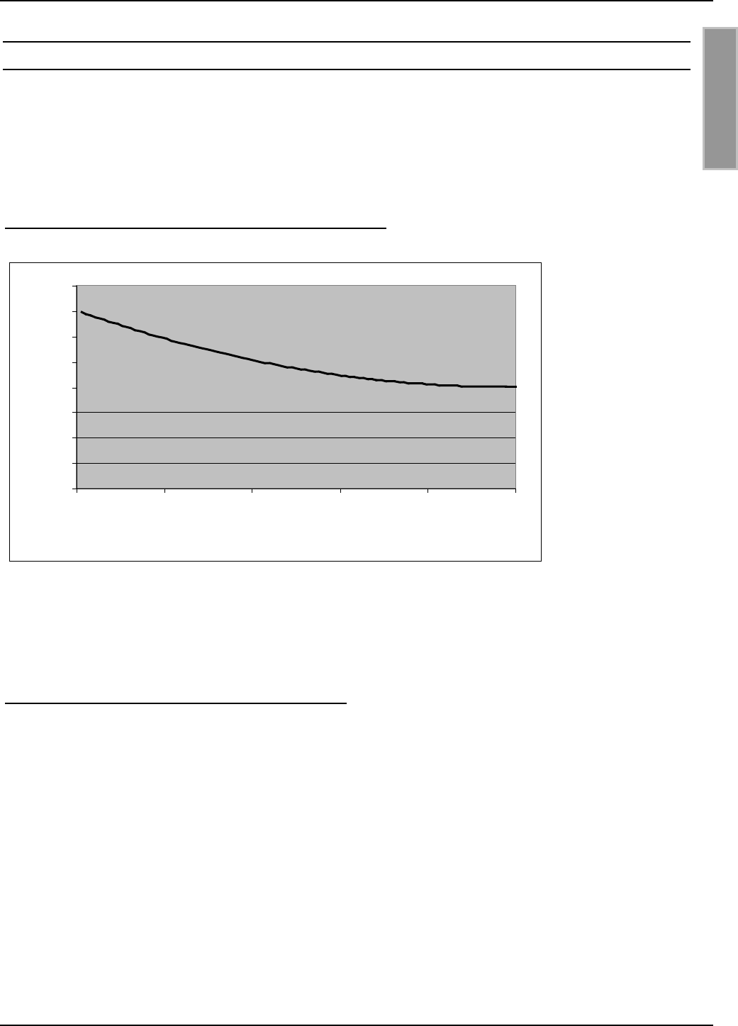
5.3. Der Einfluß von Metall auf die Reichweite
Metall und andere leitende Stoffe kann ein magnetisches Feld nicht durchdringen. Der Feldlinien-
verlauf und die Induktivität der Antenne wird verändert und hat somit einen großen Einfluß auf die
Reichweite. Weiterhin wird das Feld durch die Gegeninduktivität bzw. die Wirbelströme im Metall
geschwächt.
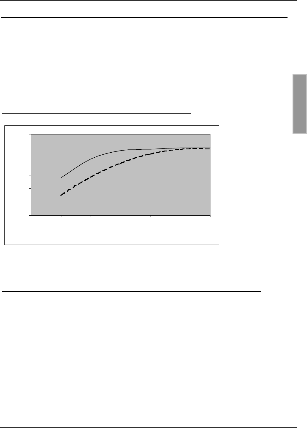
Die Änderung der Induktivität kann mit Hilfe der Abgleichelektronik ausgeglichen werden. Bild 5
zeigt den Einfluß einer Metallplatte auf die Antenne mit und ohne Nachgleich.
Bild 5: Lesereichweite* in Abhängigkeit zum Abstand zu Metall
Mit Nachgleich
Ohne Nachgleich
*Label 46 x 75 mm2, über der Antennen Mitte, Empfindlichkeit / Minimale Feldstärke Hmin=85mA/m
rms, parallele Ausrichtung des Labels zur Antenne. Sendeleistung 4 W.
Ist Metall in der Nähe der Antenne nicht zu vermeiden sollte folgendes beachtet werden:
• Mindestabstand Metall zur Antenne 10 cm. Ab 30 cm ist mit starken Einbusen der Lesereich-
weite zu rechnen. Ab 50 cm Abstand zum Metall ist nahezu kein Einfluß meßbar.
• Die Metallteile dürfen keine geschlossenen Schleifen oder Stromkreise bilden. Diese sind ge-
gebenenfalls an einer Stelle elektrisch zu trennen.
• Die Metallteile in unmittelbarer Nähe der Antenne sind mit einer guten HF-Verbindung stern-
förmig zu Erden.
30
35
40
45
50
55
60
0 102030405060
Abstand zur Metallplatte [cm]
Reichweite [cm]
OBID®Montage ID ISC.ANT300/300-A
FEIG ELECTRONIC GmbH Seite 13 von 43 M01001-2de-ID-B.DOC
D E U T S C H
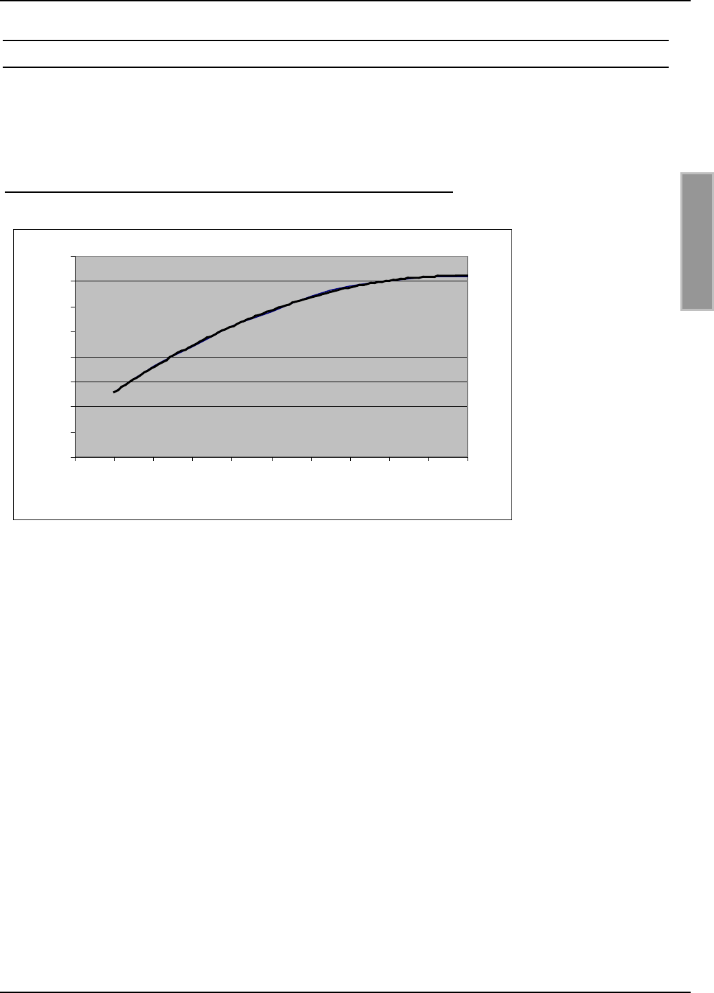
5.4. Der Einfluß der Noise Level auf die Reichweite der Antenne
Damit das Smart Label vom Empfänger auch bei kleinen Signalpegeln zuverlässig gelesen werden
kann, müssen Störungen weitgehend vermieden werden. Die Amplitude der Störpegel läßt sich am
Reader ID ISC.LR200 an Hand der Noise Level (Rausch Pegel) abfragen. Dabei sind nicht die
absoluten Meßwerte sondern die Differenz zwischen Umax und Umin ausschlaggebend.
Im folgenden Bild wurde dies bei 4 W Sendeleistung simuliert und grafisch dargestellt.
Bild 6: Lesereichweite* in Abhängigkeit der Noise Level
*Label 46 x 75 mm2 über der Antennen Mitte, Empfindlichkeit / Minimale Feldstärke Hmin=85mA/m
rms, parallele Ausrichtung des Labels zur Antenne. Sendeleistung 4 W.
Die Differenz der Noise Level (Umax-Umin) sollte kleiner gleich 20 mV sein.
Ursache für zu hohe Noise Level können sein:
• Schlechte (HF-)Verbindungen zwischen Reader und Antenne.
• Falsche Kabelführung zwischen Antenne und Reader
• Eine schlecht abgestimmte Antenne
• Störsignale von anderen elektronischen Geräten oder Sendern.
• Störsignale auf der Energieversorgungsleitung des Readers
• Störsignale von anderen Kabel in der Nähe der Kabel zum und vom Reader
• Metall in der Nähe der Antenne
20
25
30
35
40
45
50
55
60
0 100 200 300 400 500
Noise Level Umax-Umin
Reichweite [cm]

OBID®Montage ID ISC.ANT300/300-A
FEIG ELECTRONIC GmbH Seite 14 von 43 M01001-2de-ID-B.DOC
D E U T S C H
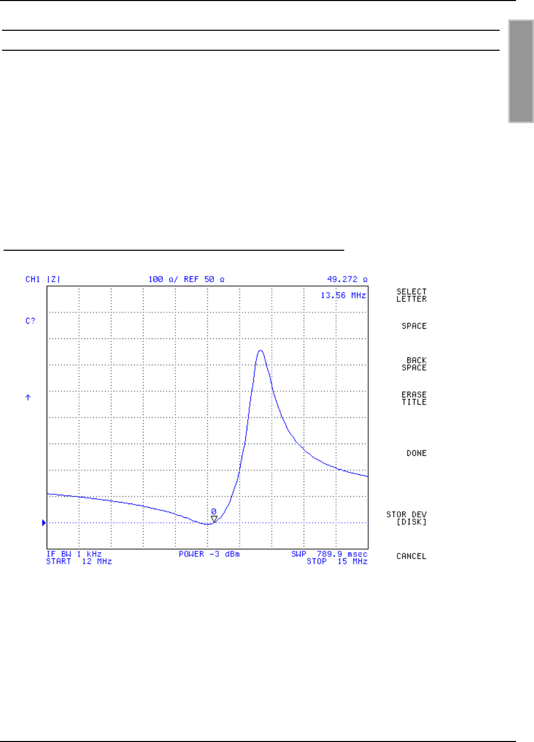
5.5. Das Messen des Stehwellenverhältnisses VSWR
Wurde eine Antenne abgeglichen oder haben sich die Umgebungsbedingungen geändert, stellt
sich die Frage: Wie gut ist die Anpassung zwischen Reader und Antenne? Ein nützliches Hilfsmit-
tel zu Beurteilung der Anpassung der Antenne an die Impedanz von 50 Ω ist das VSWR Meter.
Dieses Gerät mißt das Verhältnis zwischen zugeführter und reflektierter Energie. Dabei gilt ein
VSWR bis zu 1.3 :1 als guter Wert. In VSWR-Meter sind sehr oft auch Watt-Meter integriert.
Bild 7:Einbau eines VSWR-Meters in das Antennenkabel
Das Kabel zwischen Reader und SWR Meter sollte entweder sehr kurz (< 20 cm) oder 7,20 m (RG
58=Lamba/2) lang sein.
Liegt das VSWR nach dem Abgleichen über 1,3 : 1, kann mit Hilfe der Trimmkondensatoren C1
und C2 geringfügig nachgeglichen werden.
Weiterhin kann mit dem Gerät jederzeit die Abstimmung der Antennen kontrolliert werden. Kommt
es zu einer Verstimmung der Antenne durch Änderungen der Umgebungsbedingungen, läßt sich
dies jederzeit feststellen.
Zusätzlich zu den vom SWR angezeigten Verlusten durch die Fehlanpassung zwischen Kabel und
Antenne kommt, daß der Reader in Abhängigkeit von der Antennenimpedanz verschiedene
Ausgangsströme treibt und somit verschiedene Leistungen ausgibt. D.h bei 50 Ω fließt ein Strom
von ca. 0.3 A. Bei einem offenen Ausgang fließt kein Strom, im Kurzschlußfall wird der Strom auf
ca. 1,0 A begrenzt. Auch hat die Anpassung der Antenne einen geringen Einfluß auf die Noise
Pegel.
Basisantenne
ID ISC.
A
NT300/300
SWR / Power Meter
Reader
ID ISC.LR200
OBID®Montage ID ISC.ANT300/300-A
FEIG ELECTRONIC GmbH Seite 15 von 43 M01001-2de-ID-B.DOC
D E U T S C H
5.6. Der Abgleich der Antenne
Die Antenne wurde im Werk an einer Holzplatte auf die Impedanz von 50 Ω abgestimmt. Wird sie
in einem definierten Abstand von Metall oder anderen leitenden Stoffen montiert, ist keinerlei ab-
gleichen oder nachgleichen der Antenne notwendig.
Nach der Montage in anderen Umgebungsbedingungen kann die Antenne mit Hilfe von Jumpern
und Trimmkondensatoren Bereich neu abgestimmt werden. Dafür sollte entweder ein SWR – Me-
ter oder ein Meßgerät zur Bestimmung der Impedanz bei 13,56 MHz (Antennen/Impedanz Analy-
zer) vorhanden sein.
Vor dem Abgleichen der Basisantenne muß die Antenne und das Antennenkabel fest montiert
werden. Das Gerät ID ISC.ANT.T-A Transformer wird erst nach dem Abgleich der Antennen ein-
gebaut.
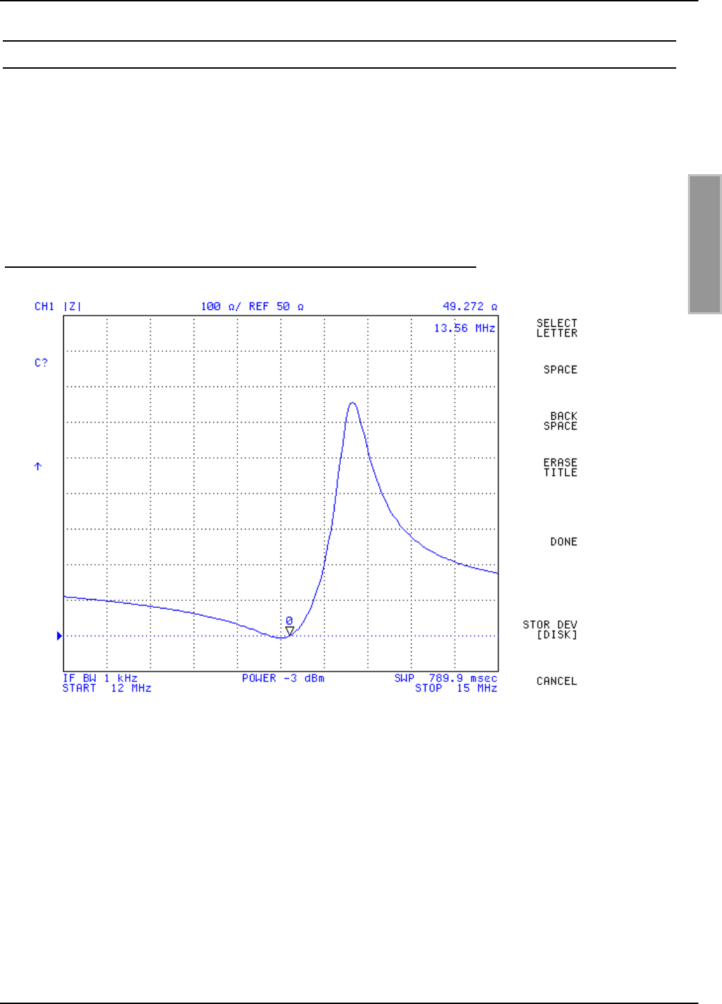
Bild 8: Die Impedanz der Antenne in Abhängigkeit von der Frequenz
Bild 8 beschreibt den Verlauf der Impedanz der Antenne ID ISC.ANT300/300-A über der Frequenz.
Wurden die Antennen richtig abgeglichen liegt das Minimum (Reihenresonaz) der Impedanzkurve
bei 13.56 MHz, 50 Ω und einem Phasenwinkel von 0°. Wird Metall in die Nähe der Antenne ge-
bracht, so verschiebt sich die Impedanzkurve Bild 8 nach rechts und leicht nach unten. D.h. kommt
die Antenne näher an Metall wird die Impedanz zuerst kleiner und dann immer größer. Dabei pas-
siert die Antenne wieder die 50 Ω Wert. Dieser Arbeitspunkt führt allerdings systembedingt nicht zu
OBID®Montage ID ISC.ANT300/300-A
FEIG ELECTRONIC GmbH Seite 16 von 43 M01001-2de-ID-B.DOC
D E U T S C H
optimalen Lesereichweiten. Der optimale Arbeitspunkt liegt immer auf der Serienresonanz welcher
hier dem Minimum in der Impedanzkurve entspricht.
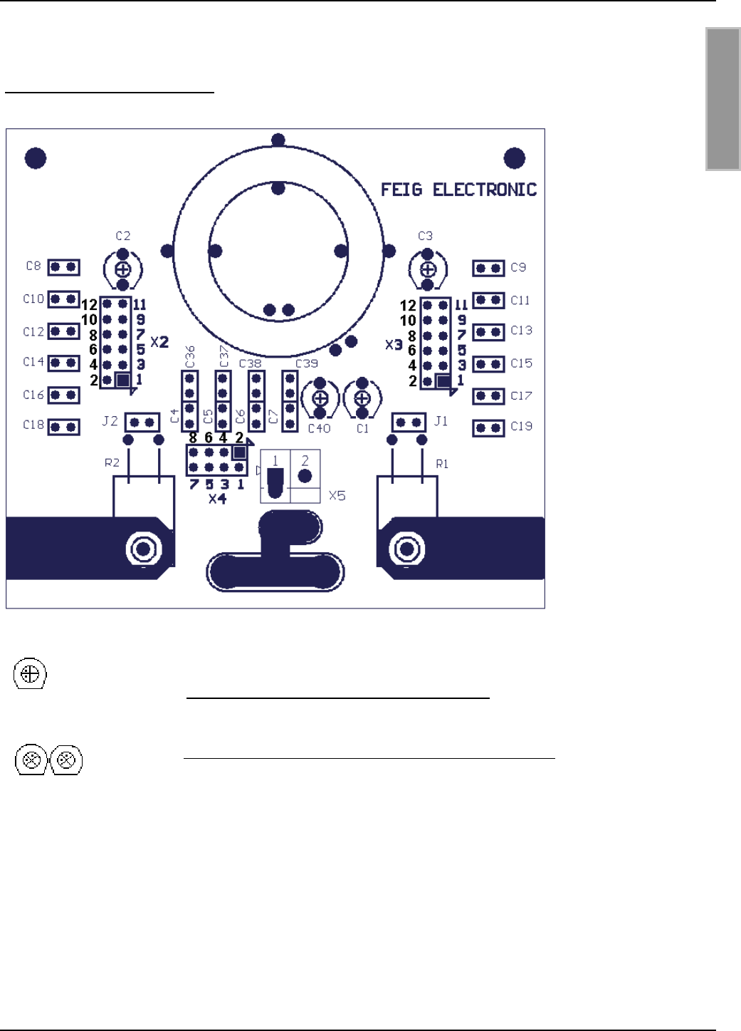
Bild 9: Draufsicht : Leiterplatte
Bild 10 : Trimmkondensator in Mittelstellung
Bild 11: 2 Trimmkondensatoren mit gleicher Kapazität
Die jeweils zusammengehörigen Trimmkondensatoren sollten immer ungefähr auf die gleiche Ka-
pazität eingestellt sein.
Um die Antenne wieder auf 50 Ω nachzugleichen, kann mit Hilfe der Trimmkondensatoren C1, C2,
C3 und C40 nachgetrimmt werden. Siehe 5.5. Das Messen des Stehwellenverhältnisses VSWR.
Reicht der Einstellbereich der Trimmkondensatoren nicht aus so kann mit Hilfe der Jumperleisten
X2,X3 und X4 vorher grob eingestellt werden.

OBID®Montage ID ISC.ANT300/300-A
FEIG ELECTRONIC GmbH Seite 17 von 43 M01001-2de-ID-B.DOC
D E U T S C H
Dabei ist folgendermaßen vorzugehen:
• Einstellen der Kondensatoren C1,C2, C3 und C40 auf Mittelstellung
• Einstellen der Kapazitäten X2,X3 auf den besten Wert Nahe 50 Ω
• Einstellen der Kapazitäten X4 auf den besten Wert Nahe 50 Ω
• Trimmen der Kapazität C2 und C3 auf den besten Wert Nahe 50 Ω.
• Trimmen der Kapazität C1 und C40 auf 50 Ω ± 1 Ω und Phasenwinkel 0°± 3°
Zum Trimmen der Kondensatoren empfehlen wir den im Anhang beschriebenen Bernsteinschrau-
bendreher.
Achtung: Am Antennenleiter oder an verschiedenen Bauteilen der Abgleichplatinen können
Spannungen bis zu 1000V auftreten. Vor dem Beginn der Arbeiten muß die Antenne von
dem Reader getrennt werden. Beim Abgleichen ist darauf zu achten, daß keine Bauteile in-
nerhalb des Gehäuse berührt werden.
Um den Abgleich zu erleichtern wurde folgende Tabelle erstellt, die als Richtwert für den Einstell-
vorgang benutzt werden kann.
Tabelle 1: Jumperpositionen
Jumper gestecktAbstand zur Metall-
platte X2 X3 X4
10 cm 5-6,7-8,11-12 5-6,7-8,11-12 1-2,3-4,5-6,7-8
20 cm 1-2,7-8,11-12 1-2,7-8,11-12 3-4,5-6,7-8
30 cm 7-8,11-12 7-8,11-12 3-4,5-6,7-8
40 cm 7-8,11-12 7-8,11-12 3-4,5-6,7-8
50 cm 7-8,11-12 7-8,11-12 3-4,5-6,7-8
60 cm 7-8,11-12 7-8,11-12 3-4,5-6,7-8
Ohne Metallplatte 7-8,11-12 7-8,11-12 3-4,5-6,7-8
Die Einstellung ohne Metallplatte ist die Standardeinstellung !

OBID®Montage ID ISC.ANT300/300-A
FEIG ELECTRONIC GmbH Seite 18 von 43 M01001-2de-ID-B.DOC
D E U T S C H
6. Der Verlauf der magnetischen Feldlinien der Antenne
Bild 12 zeigt die Feldausrichtung einer einfachen Single Loop Antenne. Sie ist die einfachste und
am meisten verwendete Antennenform im Bereich OBID i-scan. Die Antennengröße hängt dabei
stark von den Anforderungen an die Lesereichweite und der Einsatzumgebung und den nationalen
Grenzwerten ab.
Bild 12:Verlauf der magnetischen Feldlinien einer Single Loop Antenne
Die Reichweite einer Antenne ist abhängig von Position und Ausrichtung des Smart Labels. Eine
Single Loop Antenne hat die größte Reichweite in der Mitte der Antenne und einer Ausrichtung des
Smart Labels parallel zur Antennenfläche.
Label

OBID®Montage ID ISC.ANT300/300-A
FEIG ELECTRONIC GmbH Seite 19 von 43 M01001-2de-ID-B.DOC
D E U T S C H
7. Technische Daten ID ISC.ANT300/300
Mechanische Daten
• Gehäuse Kunststoff ASA
• Abmessungen ( B x H x T ) 322 mm x 337 mm x 40 mm ± 1 mm
• Gewicht ca. 0,7 kg
• Schutzart IP 65
• Farbe Schwarz
Elektrische Daten
• Maximale Sendeleistung 8 W
• Zulässige Sendeleistung
– EU-Raum (lt. EN 300 330)
– USA (FCC Part 15)
4,0 W
1,5 W
• Betriebsfrequenz 13.56 MHz
• Reichweite Maximal 55 cm *
• Antennenanschluß 1 x SMA Stecker (50 Ω)
• Antennenanschlußkabel RG58, 50 Ω, ca. 3,6 m lang
Umgebungsbedingungen
• Temperaturbereich
– Betrieb
– Lagerung
–25°C bis +55°C
–25°C bis +60°C
• Vibration EN60068-2-6
10 Hz bis 150 Hz : 0,075 mm / 1 g
• Schock EN60068-2-27
Beschleunigung : 30 g

OBID®Montage ID ISC.ANT300/300-A
FEIG ELECTRONIC GmbH Seite 20 von 43 M01001-2de-ID-B.DOC
D E U T S C H
Angewendete Normen
• EMV EN 300 683
• Sicherheit
– Europa
– USA
EN 60950 (Auf Anfrage)
UL 1950 (Auf Anfrage)
*Label 46 x 75 mm2, über der Antennen Mitte, Empfindlichkeit / Minimale Feldstärke Hmin=85mA/m
rms, parallele Ausrichtung des Labels zur Antenne. Sendeleistung 4 W.

OBID®Montage ID ISC.ANT300/300-A
FEIG ELECTRONIC GmbH Seite 21 von 43 M01001-2de-ID-B.DOC
D E U T S C H
8. Anhang Hilfreiche Werkzeuge für den Aufbau und Test der Antennen
Für die Fehlersuche oder Inbetriebnahme der Antennen werden folgende Geräte empfohlen:
• Laptop oder Personal Computer (PC) mit dem Betriebssystem (Microsoft Windows 95, 98, ME,
2000, XP).
• Servicesoftware ISCStart. Die Software ISCStart finden Sie auf der OBID® i-scan CD der Fir-
ma FEIG ELECTRONIC GmbH.
• SWR und Power Meter inklusive der Adapter auf SMA
• Abgleich- bzw. Bernsteinschraubendreher mit Kunststoffklinge 2,4x0,5mm
• 1 Stück Kabel RG 58 C/U ca. 20 – 25 cm lang mit zwei SMA Steckern (In der Regel Selbst-
bau).
Optional sind folgende Werkzeuge hilfreich:
• HF Impedanz Analyser (Für 13,56 MHz)
• Oszilloskope 2 Kanäle, Zeitbasis mindestens 10ns/Div bzw. analog Bandbreite von 100 MHz
• 1 Stück Meßschleife1 1,5 m lang (Bestehend aus 50 Ohm, RG58 Kabel mit BNC Stecker und
Drahtschleife (Durchmesser ca. 75 mm) am anderen Ende, (In der Regel Selbstbau)
Schirm
Innenleiter
BNC-Stecker
RG58 Kabel 2,5 m
ø 75

OBID®Montage ID ISC.ANT300/300-A
FEIG ELECTRONIC GmbH Seite 22 von 43 M01001-2de-ID-B.DOC
D E U T S C H
8.1. Gerätevorschläge und mögliche Bezugsquellen :
1. VSWR – Meter
Alan VSWR & Power – Meter KW 220
Lieferanten:
• CB Funkshop Rößner, 91637 Wörnitz, Tel.09868/932945, http://www.cb-funkshop.de
• AEA, Vista, California 92083, USA
• Garant – Funk, 53879 Euskirchen, Tel. 02251/55757
Alan CTE Internaltional VSWR und Wattmeter K155
Lieferant :
• Conrad Electronic
2. Antennen Analyzer
MFJ HF/UHF SWR Analyzer
Model MFJ-259B, 1.8 – 170 MHz
Lieferanten:
• Austin Amateur Radio Supply, USA 1-800 423 2604
• VHT – Impex, Ecke, Deutschland, Tel.: 05224/9709-0
CIA – HF Complex Impedance Analyzer 5012 – 5000
Lieferanten:
• AEA, Vista, California 92083, USA
• Garant – Funk, 53879 Euskirchen, Tel. 02251/55757
3. Adapter : UHF-> BNC, BNC-SMA, SMA-SMA, Abschlußwiderstand 50 Ω
Lieferanten:
• Bürklin OHG, http://www.buerklin.com
• Conrad.com AG, http://www.conrad.de
• Farnell Electronic Components GmbH, 82041 Oberhaching, http://www.farnell.com

OBID®Montage ID ISC.ANT300/300-A
FEIG ELECTRONIC GmbH Seite 23 von 43 M01001-2de-ID-B.DOC
D E U T S C H

OBID®Installation ID ISC.ANT300/300-A
FEIG ELECTRONIC GmbH Page 24 of 43 M01001-2de-ID-B.DOC
E N G L I S H
Delivery volume:
• 1 antenna ID ISC.ANT300/300-A including connection cable
• Mounting instructions
The user is cautioned that changes or modifications not expressly approved by the
FEIG ELECTRONIC GmbH could void they our authority to operate this equipment.
Note
Copyright 2002 by
FEIG ELECTRONIC GmbH
Lange Strasse 4
D-35781 Weilburg-Waldhausen
Tel.: +49 6471 3109-0
http://www.feig.de
Edition: wm/02/06/05 - m01001-2de-id-b.doc
With the edition of this document, all previous editions become void. Indications made in this manual may be
changed without previous notice.
Copying of this document, and giving it to others and the use or communication of the contents thereof are
forbidden without express authority. Offenders are liable to the payment of damages. All rights are reserved
in the event of the grant of a patent or the registration of a utility model or design.
Composition of the information in this manual has been done to the best of our knowledge. FEIG
ELECTRONIC GmbH does not guarantee the correctness and completeness of the details given in this
manual and may not be held liable for damages ensuing from incorrect or incomplete information. Since,
despite all our efforts, errors may not be completely avoided, we are always grateful for your useful tips.
The installation instructions given in this manual are based on advantageous boundary conditions. FEIG
ELECTRONIC GmbH does not give any guarantee promise for perfect function in cross environments.
FEIG ELECTRONIC GmbH assumes no responsibility for the use of any information contained in this
manual and makes no representation that they free of patent infringement. FEIG ELECTRONIC GmbH does
not convey any license under its patent rights nor the rights of others.
OBID® is registered trademark of FEIG ELECTRONIC GmbH.

OBID®Installation ID ISC.ANT300/300-A
FEIG ELECTRONIC GmbH Page 25 of 43 M01001-2de-ID-B.DOC
E N G L I S H
Contents
1. Safety Instructions / Warning - Read before start-up ! 26
2. Functional description of the OBID® i-scan-system 27
3. Features of performance of antenna ID ISC.ANT300/300 27
4. Assembly and wiring 28
5. Startup 30
5.1 Radio regulations in the European Community and the U.S. .........................................30
5.2 The influence of the transmitting power on the reading range ......................................31
5.3 The influence of metal on the reading range....................................................................32
5.4 The influence of the noise level on the antenna’s working range..................................33
5.5 How to measure the voltage standing wave ratio (VSWR)..............................................34
5.6 Antenna tuning ....................................................................................................................35
6. Course of the antenna’s magnetic lines of electric flux 38
7. Technical data of ID ISC.ANT300/300 39
8. Appendix: useful tools for installation and testing 41
8.1 Recommended equipment and possible sources: ..........................................................42

OBID®Installation ID ISC.ANT300/300-A
FEIG ELECTRONIC GmbH Page 26 of 43 M01001-2de-ID-B.DOC
E N G L I S H
1. Safety Instructions / Warning - Read before start-up !
• The device has to be used only for the purpose designed by the manufacturer.
• The operation manual has to be stored available at any time and has to be handed over to
each user.
• Unauthorized changes and the use of spare parts and additional devices which have not been
sold or recommended by the manufacturer may cause fire, electric shocks or injuries. Such
measures will lead to exclusion of any liability by the manufacturer.
• The liability-prescriptions of the manufacturer in the issue valid at the time of purchase are valid
for the device. The manufacturer is not legally responsible for incorrect, unsuitable manual or
automatical setting of parameters for a device or the incorrect application of a device.
• Repairs can only be executed by the manufacturer.
• Installation-, operation- and maintenance procedures should only be carried out by qualified
personnel.
• Before opening the device, the power supply must always be interrupted. Make sure that the
device is without voltage by measuring. CAUTION! The fading of an operation control (LED) is
no indicator for an interrupted power supply or the device being without voltage!
• Works at the device and its installation have to be executed according to the national legal
requirements and local prescriptions.
• When working on devices the valid safety regulations must be observed.
• When working on an opened device note that the components may carry voltages of up to
1000V.

OBID®Installation ID ISC.ANT300/300-A
FEIG ELECTRONIC GmbH Page 27 of 43 M01001-2de-ID-B.DOC
E N G L I S H
2. Functional description of the OBID® i-scan-system
The identification system OBID® i-scan is an inductive transmission system for touchless identifi-
cation (ID) of moving objects. The components of the write/read system facilitate the writing and
reading of passive data carriers (Transponder) with an actual frequency of 13.56 MHz, the so-
called „smart labels“. It consists of a reader ID ISC.LR200, one or several antennas and one or
more smart labels used as a data storage medium.
These smart labels are generally paper badges or tags with a wafer-thin transponder integrated for
communicating with RFID read/write devices.
If a smart label gets into the antenna’s local magnetic field, it is powered and may be read and
written. Data is received by the same reader antenna that also produces the magnetic field and
sends the data to the data carrier.
The magnetic field and all data sent and received by the data carrier are able to penetrate almost
all non-conductive materials, so that even hidden writing and reading is possible.
The reader’s anticollision function facilitates the simultaneous reading of up to 50 smart labels per
second.
3. Features of performance of antenna ID ISC.ANT300/300
The Antenna ID ISC.ANT300/300 is a single-loop antenna with pre-set adjustment electronics and
has been optimized as a transmitting- and reception antenna for reader ID ISC.LR200. . At a cali-
brated transmitting power of 4 W a reading range of up to 55 cm is possible. Furthermore, it can be
used with other readers having a transmitter frequency of 13.56 MHz and an output impedance of
50 Ω.
The antenna has been factory calibrated on a wood block for an impedance of 50 Ω. After having
been installed in other surroundings, the antenna may be re-tuned for a defined range with the help
of jumpers.
The antenna is suitable for both object- and personal identification. The preferred direction of a
smart label is parallel to the antenna’s surface. The right position to obtain a maximum range
would be above the centre of the antenna’s surface.

OBID®Installation ID ISC.ANT300/300-A
FEIG ELECTRONIC GmbH Page 28 of 43 M01001-2de-ID-B.DOC
E N G L I S H
322±2
267±1
40+0,5
-1,0 267±1
322±2
337±2
38±0,5
28±0,5
13 0,0
-1,0
5,6±0,2
4. Assembly and wiring
The antenna has been especially designed for installation with holding devices made of non-
conductive materials (e.g. plastic or wood). It is suitable for both indoor as well as outdoor use. In
order to facilitate the mounting, there are 4 bores (d=5,6 mm) with a spacing of 264 mm at the in-
side of the antenna. For attachment, we recommend a wood screw (like DIN 96) or machine screw
(like DIN 7985) with a pen head of minimum ∅ 10 mm till maximum ∅ 12 mm. The maximum tight-
ening torque of the free turning screws are 2 Nm.
If these existing bores are not sufficient, you can drill additional holes (d=5.6 mm) within the
hatched area shown in Figure13
Please keep a minimum distance of 10 cm to all metal parts! Even a distance of 50 cm to
metal parts will lead to a reduction of the reading range.
Figure13: installation drawing ID ISC.ANT300/300
All
measurements in mm.
For antenna tuning open the housing by removing the four screws at the cover. The maximum
tightening torque for the cover screws is 0,2 Nm – 0,25 Nm.
antenna opening
(cover)

OBID®Installation ID ISC.ANT300/300-A
FEIG ELECTRONIC GmbH Page 29 of 43 M01001-2de-ID-B.DOC
E N G L I S H
The antenna is connected directly to the reader with the help of the connecting cable and the SMA-
plug. For industrial environments, we recommend to insert the ID ISC.ANT.T transformer between
reader and antenna.
Figure 14: Wiring diagram - reader with transformer and base antenna
In order to suppress possible interferences, reader ID ISC.LR200 is equipped with two toroidal
cores. As far as possible, one of these toroidal cores should be integrated into the antenna con-
nection cable. For this purpose, the coaxial cable has to be pulled through the core 4 times and
has to be located as close as possible to the core. The maximum distance between reader and
toroidal coures should be 10 cm.
Figure 15: Assembly of the toroidal core at the coaxial cable
Please also observe the following recommendations:
• Up to a distance of 50 cm, the antenna cable should always be lead away from the antenna
vertically and installed permanently.
• In order to obtain an optimum reading range, the antenna connection cable should not be
shortened or extended. If an extension is absolutely necessary, please use a 50 Ω cable with a
length of 2
λ
(half the wavelength at 13,56 MHz, RG58=7,20 m). However, this may lead to a
minor sensitivity reduction (approx. 2 cm readding range / extension).
• Please keep a minimum distance of 30 cm between the antenna cable and all parallel, power
cables.
After the installation has been completed, an operational check can be performed with the help of
the reader and a smart label. With a transmitting power of 4W and a label size of 70 mm x 54 mm
(ISO-card size) the reading range in the centre of the antenna should be approx. 50 cm – 55 cm.
Otherwise, the adjustment of the antenna to the impedance of 50 Ω should be checked with the
help of an SWR – Meter. In addition to that, you should also check the noise level at the reader.
Reade
r
ID ISC.ANT.T
ID ISC.ANT300/300

OBID®Installation ID ISC.ANT300/300-A
FEIG ELECTRONIC GmbH Page 30 of 43 M01001-2de-ID-B.DOC
E N G L I S H
5. Startup
5.1 Radio regulations in the European Community and the U.S.
Under optimal ambient conditions and in connection with reader ID ISC.LR200 , the antenna can
be operated with maximum 4.0 W in Europe and maximum 1.5 W in the U.S.. In case of higher or
lower limiting values, please adjust the transmitting power or reduce the magnetic radiation by us-
ing a radio shield.
The design and RF power of the antennas is affected mainly by the country-specific RF regula-
tions. The entire EU geographic area is covered under uniform limits specified in the R&TTE
guideline and EN 300 330. In North America this is regulated by FCC Part 15.
In EU countries the maximum permissible field strength at 13.56 MHz at a distance of 10 m is:
42dBµA/m. In the U.S. this is 38dBµA/m.
Since FCC Part 15 prescribes a separation of 50 dB between the carrier and sidebands, the
Reader may be operated in the USA only using 1 of 256 bit coding (modulation).
Under optimal ambient conditions and in connection with reader ID ISC.LR200 , the antenna can
be operated with maximum 4.0 W in Europe and maximum 1.5 W in the U.S.. In case of higher or
lower limiting values, please adjust the transmitting power or reduce the magnetic radiation by us-
ing a radio shield.
When commissioning the antennas, the system integrator and installer should be sure that the in-
stallation instructions are followed, the necessary Reader settings have been made and that the
limit values prescribed by the national regulatory agency are not exceeded.
Furthermore the Reader must be configured as follows:
Parameter Europe U.S.
General
RF-Power – CFG 3 4 W 1.5 W
ISO15693 Label
Downlink RF Modulation – CFG
8 / ISO-MODE / MOD
10 % 10%
Downlink RF Data coding –
CFG 8 / ISO-MODE / FAST
Fast (1/4) or Normal (1/256) Normal (1/256)
Timeslots - CFG 8 / ISO-MODE
/ NO-TS
16 Timeslots 16 Timeslots
Inventory Command Option –
CFG 8 / ISO-CMD-OPTION /
BREAK
Complete Timeslot length at
“NO TAG“
Complete Timeslot length at
“NO TAG“
I-Code 1
Downlink RF Data coding –
CFG 8 / ICODE-MODE / FAST
Fast Mode (1/1) or Normal
Mode (1/256)
- Normal Mode (1/256)
OBID®Installation ID ISC.ANT300/300-A
FEIG ELECTRONIC GmbH Page 31 of 43 M01001-2de-ID-B.DOC
E N G L I S H
5.2 The influence of the transmitting power on the reading range
The antenna’s working range is dependent on the antenna itself, the reader, the smart label and
the adjusted transmitting power of the reader. Due to the fact that the smart label gets its energy
from the magnetic field produced by the antenna and that the field intensity decreases at higher
distances, the radiated transmitting power has strong influence on the range.
Figure 16: reading range* in dependance on the transmitting power
*Label 46 x 75 mm2, over the centre of the antenna, sensitivity / minimum operating field
Hmin=85mA/m rms, parallel orientation to the antenna,. transmitting power 4 W.
A transmitting power of more than 8 W could, in dependance on the ambient temperature, heat up
the antenna and may even destroy it.
30
35
40
45
50
55
60
65
70
012345678910
transmitting power [W]
reading range [cm]
OBID®Installation ID ISC.ANT300/300-A
FEIG ELECTRONIC GmbH Page 32 of 43 M01001-2de-ID-B.DOC
E N G L I S H
5.3 The influence of metal on the reading range
A magnetic field cannot penetrate metal or other magnetically conductive materials. The course of
the lines of electric flux and the inductivity of the antenna is changed and has therefore a consider-
able influence on the reading range. Furthermore, the filed is weakened by the mutual inductance
response the eddy current within the metal.
The change of inductivity may often be compensated with the help of the tuning electronics. Figure
17 illustrates the influence of a metal plate on the antenna with (upper line) and without rebalanc-
ing.
Figure 17: reading range* in dependance on the distance to metal
*Label 46 x 75 mm2, over the centre of the antenna, sensitivity / minimum operating field
Hmin=85mA/m rms, parallel orientation to the antenna,. transmitting power 4 W.
If metal parts cannot be avoided close to the antenna, please observe the following:
• The minimum distance between metal and antenna is 10 cm. A distance of 30 cm will lead to a
considerable reduction in the reading range. At a distance of 50 cm to metal parts, there will be
almost no influence to be measured.
• Metal parts must not form closed loops or electric circuits. These have to be electrically sepa-
rated at one point.
• Metal parts in close vicinity to the antenna have to be grounded in star configuration with a
good HF-connection.
30
35
40
45
50
55
60
0 102030405060
distance to metal [cm]
reading range [cm]

OBID®Installation ID ISC.ANT300/300-A
FEIG ELECTRONIC GmbH Page 33 of 43 M01001-2de-ID-B.DOC
E N G L I S H
5.4 The influence of the noise level on the antenna’s working range
Interferences have to be largely avoided, so that the smart label may be read by the receiver even
at low signal levels. The amplitude of the interference levels can be found out at reader
ID ISC.LR200 with the help of the noise levels. Critical are not the absolute measured values, but
rather the difference between Umax-Umin.
This has been simulated at 4W and represented graphically in the following figure.
Figure 18: reading range* in dependance on the noise levels
*Label 46 x 75 mm2, over the centre of the antenna, sensitivity / minimum operating field
Hmin=85mA/m rms, parallel orientation to the antenna,. transmitting power 4 W.
The difference of the noise levels (Umax - Umin) should be less than 20 mV.
Possible reasons for excessive noise levels:
• Bad (HF-)connections between reader and antenna.
• Improper cable layout between antenna and reader
• Badly tuned antenna
• Interfering signals of other electronic appliances or transmitting stations.
• Interfering signals on the reader’s power supply line.
• Interfering signals coming from other cables close to the cables leading to and away from the
reader.
• Metal parts close to the antenna
20
25
30
35
40
45
50
55
60
0 100 200 300 400 500
Noise Level Umax-Umin
reading range [cm]

OBID®Installation ID ISC.ANT300/300-A
FEIG ELECTRONIC GmbH Page 34 of 43 M01001-2de-ID-B.DOC
E N G L I S H
5.5 How to measure the voltage standing wave ratio (VSWR)
If an antenna has been tuned, the question is: how good is the adjustment between reader and
antenna? In this case, the VSWR –meter is a very useful aid. This device measures the ratio be-
tween supplied and reflected energy. A VSWR of up to 1.3 :1 is considered to be sufficient. Very
often, a wattmeter is integrated into these devices.
Figure 19:Inserting a VSWR meter into the antenna cable
The cable between the Reader and the SWR meter should either be very short (< 20 cm) or 7.20
m (RG 58=Lambda/2) long. If the VSWR is greater than 1.3:1 after tuning, use trim capacitors C1
and C2 on the board of the base antenna to perform a slight adjustment.
Furthermore the VSWR meter can be used at any time to check the tuning of the base antennas. If
changes in local conditions result in detuning of the antennas, this can be verified whenever
desired.
In addition to the losses indicated by the SWR due to mismatching between the cable and the
antenna, it happens that the Reader drives different output currents depending on the antenna
impedance, resulting in power variance. This means that at 50 Ω a current of approx. 0.3 A flows.
No current flows when an output is open, and when there is a short circuit the current is limited to
approx. 1.0 A. Matching the antenna also has a slight effect on the noise levels.
base antenna
ID ISC.
A
NT300/300
SWR / Power Meter
Reader
ID ISC.LR200
OBID®Installation ID ISC.ANT300/300-A
FEIG ELECTRONIC GmbH Page 35 of 43 M01001-2de-ID-B.DOC
E N G L I S H
5.6 Antenna tuning
The antenna has been factory-tuned on a wood block at an impedance of 50 Ω. If it is installed in a
defined distance to metal or other magnetically conductive materials, no adjustment or re-
adjustment will be necessary.
After installation in different ambiance conditions, the antenna may be re-tuned for a limited sector
with the help of jumpers and trimming capacitors. For this purpose you will either need an SWR –
meter or a measuring device (antenna/impedance analyzer) in order to determine the impedance
at 13,56 MHz.
Figure 20: The antenna’s impedance in dependance on the frequency
If metal is brought close to the antenna, the impedance curve (Figure 20) shifts to the right and
slightly downwards. This means that the closer the metal part comes, the impedance value will
decrease and then increase more and more. During this process, the antenna will once again pass
the value of 50 Ω. However, this operating point does not lead to optimal reading ranges. The op-
timal operating point always lies on the series resonance, which in this case equals the minimum
value on the impedance curve.
OBID®Installation ID ISC.ANT300/300-A
FEIG ELECTRONIC GmbH Page 36 of 43 M01001-2de-ID-B.DOC
E N G L I S H
Figure 21: Top view: Circuit board
Figure 22 : trimming capacitor at neutral position
Figure 23: two trimming capacitors with equal C-values
The trim capacitor pairs (C2,C3 or C1,C40) should always to set to approximately the same ca-
pacitance. Maximum capacitance is reached when both dots point to the tip (up in this example),
and minimum capacitance is set when both dots point towards the flat side.
In order to re-adjust the antenna on 50 Ω and phase angle 0°, trimming capacitors C1, C2, C3 and
C40 may be used for re-trimming. See chapter 5.5 How to measure the voltage standing wave
ratio (VSWR). Should the setting range of the trimming capacitors be insufficient, jumper terminals
X2,X3 and X4 may be used for a rough pre-adjustment.

OBID®Installation ID ISC.ANT300/300-A
FEIG ELECTRONIC GmbH Page 37 of 43 M01001-2de-ID-B.DOC
E N G L I S H
Please proceed as follows:
• Adjust capacities C1,C2, C3 and C40 at the neutral position (see Figure 22)
• Adjust capacities X2,X3 at the optimal value lying close to 50 Ω
• Adjust capacities X4 at the optimal value lying close to 50 Ω
• Trim capacity C2 and C3 optimal value lying close to 50 Ω.
• Trim capacity C1 and C40 at 50 Ω ± 1 Ω and phase angle 0°± 3°
For trimming the capacitors, we recommend an amber- /adjustment screwdriver
Note: Voltages as high as 1000V may be present on the antenna wire or on various compo-
nents of the tuning boards. Before starting your work first disconnect the antenna from the
Reader. When tuning the antenna make sure no components inside the housing are
touched.
The following chart has been made up in order to facilitate this process. It may be used as a guide-
line value for the adjustment process.
Chart 2: Jumper positions
Jumpers, insertedDistance to metal
plate X2 X3 X4
10 cm 5-6,7-8,11-12 5-6,7-8,11-12 1-2,3-4,5-6,7-8
20 cm 1-2,7-8,11-12 1-2,7-8,11-12 3-4,5-6,7-8
30 cm 7-8,11-12 7-8,11-12 3-4,5-6,7-8
40 cm 7-8,11-12 7-8,11-12 3-4,5-6,7-8
50 cm 7-8,11-12 7-8,11-12 3-4,5-6,7-8
60 cm 7-8,11-12 7-8,11-12 3-4,5-6,7-8
Without metal plate 7-8,11-12 7-8,11-12 3-4,5-6,7-8

OBID®Installation ID ISC.ANT300/300-A
FEIG ELECTRONIC GmbH Page 38 of 43 M01001-2de-ID-B.DOC
E N G L I S H
6. Course of the antenna’s magnetic lines of electric flux
Figure 24 shows the field alignment of a simple single loop antenna. This is the most simple and
most frequently used antenna type in the sector of OBID i-scan. Its size depends highly on the
reading range requirements and the place of application as well as the national limiting values.
Figure 24: course of the magnetic lines of electric flux of a single loop antenna
The working range of an antenna depends very much on the position and alignment of the smart
label. A single loop antenna has the highest range in the centre of the antenna and if the smart
label is aligned parallel to the antennas surface.
Label

OBID®Installation ID ISC.ANT300/300-A
FEIG ELECTRONIC GmbH Page 39 of 43 M01001-2de-ID-B.DOC
E N G L I S H
7. Technical data of ID ISC.ANT300/300
Mechanical data
• Housing Plastic ABS
• Dimensions ( W x H x L ) 322 mm x 337 mm x 40 mm ± 1 mm
• Weight approx. 0,7 kg
• Protection class IP 65
• Colour Black
Electrical data
• Maximum transmitting power 8 W
• Admissible transmitting power
– EU (according EN 300 330)
– U.S. (according FCC Part 15)
4.0 W
1.5 W
• Operating frequency 13.56 MHz
• Working range Maximum 55 cm *
• Antenna connection 1 x SMA plug (50 Ω)
• Antenna connection cable RG58, 50 Ω, approx. length of 3,6 m
Ambiance conditions
• Temperature range
– operation
– storage
–25°C to +55°C
–25°C to +60°C
• Vibration EN60068-2-6
10 Hz to 150 Hz :0,075 mm / 1 g
• Shock EN60068-2-27
Acceleration : 30 g

OBID®Installation ID ISC.ANT300/300-A
FEIG ELECTRONIC GmbH Page 40 of 43 M01001-2de-ID-B.DOC
E N G L I S H
Applicable standards
• EMV EN 300 683
• Safety
– Europe
– U.S.
EN 60950 (on request)
UL 1950 (on request)
*Label 46 x 75 mm2,, over the centre of the antenna, sensitivity / minimum operating field
Hmin=85mA/m rms, parallel orientation to the antenna,. transmitting power 4 W.

OBID®Installation ID ISC.ANT300/300-A
FEIG ELECTRONIC GmbH Page 41 of 43 M01001-2de-ID-B.DOC
E N G L I S H
8. Appendix: useful tools for installation and testing
We recommend the following devices for trouble shooting and initiation of the antennas:
• Laptop or personal computer (PC) running under Microsoft Windows 95, 98, ME, 2000.
• Service software ISCStart (V4.02 or higher). This software can be found on the OBID® i-scan
CD-ROM supplied by FEIG ELECTRONIC GmbH..
• SWR and Power Meter including SMA connectors (female) or appropriate adapters.
• Qty. 1 cable RG 58 C/U approx. 20 – 25 cm (7.8 – 9.8 in) long with two male SMA plugs (gen-
erally self-assembled).
• Adjustment- resp. amber screwdriver with a 2,4x0,5mm plastic blade
Optionally, the following tools will be useful:
• HF impedance analyser (for 13,56 MHz)
• Oszilloscopes: 2 channels, time base min. 10ns/Div resp. analog band width of 100 MHz
• 2 measuring loops, length: 1,5 m (consisting of 50 Ohm, RG58 cable with BNC plug and wire
coil (diameter approx. 75 mm) at the other end (usually self-constructed)
screen
centre conductor
BNC-plug, male
RG58 cable 2,5 m
ø 75

OBID®Installation ID ISC.ANT300/300-A
FEIG ELECTRONIC GmbH Page 42 of 43 M01001-2de-ID-B.DOC
E N G L I S H
8.1 Recommended equipment and possible sources:
1. VSWR – Meter
Alan VSWR & Power – Meter KW 220
Vendors:
• CB Funkshop Rößner, 91637 Wörnitz, Tel.09868/932945, http://www.cb-funkshop.de
• AEA, Vista, California 92083, USA
• Garant – Funk, 53879 Euskirchen, Tel. 02251/55757
Alan CTE International VSWR and Wattmeter K155
Vendor:
• Conrad Electronic
1. Antenna analyzer
MFJ HF/UHF SWR Analyzer
• Model MFJ-259B, 1.8 – 170 MHz
Vendors:
• Austin Amateur Radio Supply, USA 1-800 423 2604
• VHT – Impex, Ecke, Germany, Tel.: 05224/9709-0
CIA – HF Complex Impedance Analyzer 5012 – 5000
Vendors:
• AEA, Vista, California 92083, USA
• Garant – Funk, 53879 Euskirchen, Tel. 02251/55757
2. Adapter : UHF-> BNC, BNC-SMA, SMA-SMA, Abschlußwiderstand 50 Ω
Vendors:
• Bürklin OHG, http://www.buerklin.com
• Conrad.com AG, http://www.conrad.de
• Farnell Electronic Components GmbH, 82041 Oberhaching, http://www.farnell.com
3. Amber / Tuning screwdrivers with plastic blade
Blade size: 2,4x0,5mm
Vendors:
• Bürklin Bestellnummer 06 L 8364

OBID®Installation ID ISC.ANT300/300-A
FEIG ELECTRONIC GmbH Page 43 of 43 M01001-2de-ID-B.DOC
E N G L I S H
4. Oscilloscope
Tektronix TDS 210 or a model from the TDS2xx or TDS3xx. series
Agilent 54622D or a model from the 546xx series
Voltcraft 100 MHz- Oscilloskope 6100
Hameg HM 407 or HM 1507-3
Vendors:
• Tektronix Inc, http://www.tektronix.de oder http://www.tektronix.com
• Agilent Technoligies, http://www.agilent.com
• Conrad Electronic GmbH, 92240 Hirschau, http://www.conrad.de
• ELV Elektronik AG 26787 Leer, http://www.elv.de oder http://www.elv.com
• DataTec GmbH, 72770 Reutlingen, http://www.datatec.com
5. EMC ferrite toroid cores
Diameter da=28, di=16, I=20, B.Nr.742 701 4
Diameter da=40,6 di=27,4 I=15, B.Nr.742 701 5
Vendor
Würth Elektronik GmbH & Co.KG
Riedenstraße 16
74635 Kupferzell
Tel.: 07944 / 91 93 0
www.wuerth.de oder www.wuerth.com