Feig Electronic MR200 Inductive Reader User Manual Antenna 2
Feig Electronic GmbH Inductive Reader Users Manual Antenna 2
Contents
- 1. Users Manual
- 2. Users Manual Antenna 1
- 3. Users Manual Antenna 2
Users Manual Antenna 2
MONTAGE
INSTALLATION
final
public
2002-06-04
M01004-2de-ID-B.doc
OBI
D
®
i-scan
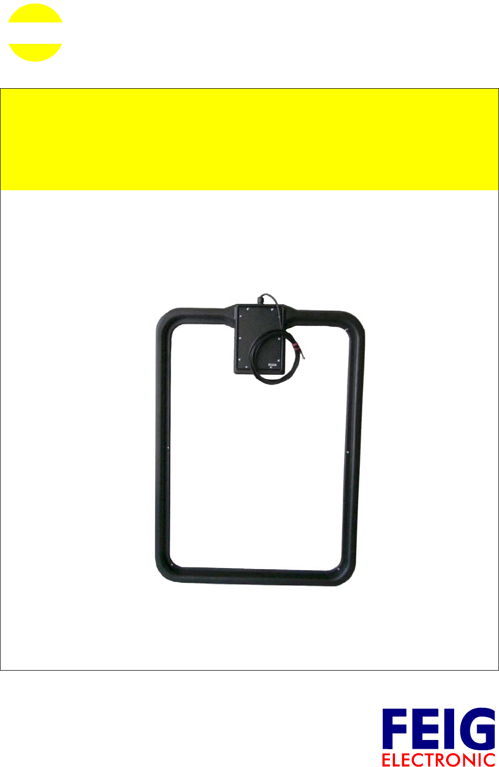
ID ISC.ANT800/600-A
ID ISC.ANT800/600-B
Basis- und Ergänzungsantenne
Base and complementary antenna
(deutsch / english)

OBID® i-scan Montage ID ISC.ANT800/600
FEIG ELECTRONIC GmbH Seite 2 von 75 M01004-2de-ID-B.doc
D E U T S C H


OBID® i-scan Montage ID ISC.ANT800/600
FEIG ELECTRONIC GmbH Seite 4 von 75 M01004-2de-ID-B.doc
D E U T S C H
Lieferumfang:
• 1 Antenne ID ISC.ANT800/600-A oder ID ISCANT800/600-B inklusive Anschlußkabel
• Montageanleitung
Hinweis
Copyright 2002 by
FEIG ELECTRONIC GmbH
Lange Straße 4
D-35781 Weilburg-Waldhausen
Tel.: +49 6471 3109-0
http://www.feig.de
Ausgabe: wm/02/06/04 - m01004-2de-id-bwm0406.doc
Alle früheren Ausgaben verlieren mit dieser Ausgabe ihre Gültigkeit.
Die Angaben in diesem Dokument können ohne vorherige Ankündigung geändert werden.
Weitergabe sowie Vervielfältigung dieses Dokuments, Verwertung und Mitteilung ihres Inhalts sind nicht
gestattet, soweit nicht ausdrücklich zugestanden. Zuwiderhandlung verpflichtet zu Schadenersatz. Alle
Rechte für den Fall der Patenterteilung oder Gebrauchsmuster-Eintragung vorbehalten.
Die Zusammenstellung der Informationen in diesem Dokument erfolgt nach bestem Wissen und Gewissen.
FEIG ELECTRONIC GmbH übernimmt keine Gewährleistung für die Richtigkeit und Vollständigkeit der An-
gaben in diesem Dokument. Insbesondere kann FEIG ELECTRONIC GmbH nicht für Folgeschäden auf
Grund fehlerhafter oder unvollständiger Angaben haftbar gemacht werden. Da sich Fehler, trotz aller Bemü-
hungen nie vollständig vermeiden lassen, sind wir für Hinweise jederzeit dankbar.
Die in diesem Dokument gemachten Installationsempfehlungen gehen von günstigsten Rahmenbedingun-
gen aus. FEIG ELECTRONIC GmbH übernimmt keine Gewähr für die einwandfreie Funktion in systemfrem-
den Umgebungen.
FEIG ELECTRONIC GmbH übernimmt keine Gewährleistung dafür, dass die in diesem Dokument enthal-
tenden Informationen frei von fremden Schutzrechten sind. FEIG ELECTRONIC GmbH erteilt mit diesem
Dokument keine Lizenzen auf eigene oder fremde Patente oder andere Schutzrechte.
OBID® ist ein eingetragenes Warenzeichen der FEIG ELECTRONIC GmbH
Allgemeine Hinweise zu diesem Handbuch
• Das Zeichen „)“ weist auf Erweiterungen bzw. Änderungen gegenüber der Vorgängerversion
hin.
• Sind Bits innerhalb eines Bytes mit dem Zeichen „-“ gefüllt, so sind diese Bitstellen i.d.R. für
zukünftige Erweiterungen reserviert oder für interne Fertigungs- und Testfunktionen belegt. Die-
se Bitstellen sollten nicht verändert werden, da dies zu einem unerwarteten Betriebsverhalten
des Geräts führen kann.
• Die verwendeten Zahlenformate sind
0...9: für dezimale Zahlenwerte und
0x00...0xFF: für hexadezimale Zahlenwerte,
b0...1 für binäre Zahlenwerte.

OBID® i-scan Montage ID ISC.ANT800/600
FEIG ELECTRONIC GmbH Seite 5 von 75 M01004-2de-ID-B.doc
D E U T S C H
Inhalt
1. Sicherheits- und Warnhinweise - vor Inbetriebnahme unbedingt lesen 7
2. Funktionsprinzip des OBID® i-scan-Systems 8
3. Leistungsmerkmale der Antenne ID ISC.ANT800/600-A Antenna Type A 8
4. Leistungsmerkmale der Antenne ID ISCANT800/600-B Antenna Type B 9
5. Mögliche Geräteanordnungen mit der Antenne ID ISC.ANT800/600 10
5.1. Mögliche Schaltungsbeispiele ..........................................................................................10
5.2. Typische Antennenaufbauten ..........................................................................................11
5.3. Zur Inbetriebnahme benötigte Komponenten ................................................................12
6. Montage und Anschluß 13
6.1. Hinweise zur Kabelführung der Antennenzuleitung ......................................................16
7. Der Abgleich der Antennen 17
7.1. Vorbereitungen..................................................................................................................18
7.2. Abgleich der Basisantenne ..............................................................................................20
7.3. Der Abgleich der zweiten Basisantenne .........................................................................23
7.4. Feinabgleich der beiden Antennen..................................................................................24
7.5. Der Abgleich der Ergänzungssantenne ..........................................................................26
8. Inbetriebnahme 27
8.1. Funk-Regularien im EU-Raum und der USA...................................................................27
8.2. Spezielle Antennenaufbauten ..........................................................................................28
8.3. Der Einfluß der Sendeleistung auf die Lesereichweite..................................................30
8.4. Der Einfluß von Metall auf die Reichweite ......................................................................31
8.5. Der Einfluß der Noise Level auf die Reichweite der Antenne .......................................32

OBID® i-scan Montage ID ISC.ANT800/600
FEIG ELECTRONIC GmbH Seite 6 von 75 M01004-2de-ID-B.doc
D E U T S C H
8.6. Das Messen des Stehwellenverhältnisses VSWR..........................................................33
8.7. Messen des Phasenwinkel und Überprüfung der Ströme in der Antenne...................34
9. Technische Daten ID ISC.ANT800/600-A und ID ISC.ANT800/600-B 35
10. Anhang A Hilfreiche Werkzeuge für den Aufbau und Test der Antennen 37
Gerätevorschläge und mögliche Bezugsquellen : .................................................................38

OBID® i-scan Montage ID ISC.ANT800/600
FEIG ELECTRONIC GmbH Seite 7 von 75 M01004-2de-ID-B.doc
D E U T S C H
1. Sicherheits- und Warnhinweise - vor Inbetriebnahme unbedingt lesen
• Das Gerät darf nur für den vom Hersteller vorgesehenen Zweck verwendet werden.
• Die Bedienungsanleitung ist zugriffsfähig aufzubewahren und jedem Benutzer auszuhändigen.
• Unzulässige Veränderungen und die Verwendung von Ersatzteilen und Zusatzeinrichtungen,
die nicht vom Hersteller des Gerätes verkauft oder empfohlen werden, können Brände, elektri-
sche Schläge und Verletzungen verursachen. Solche Maßnahmen führen daher zu einem
Ausschluß der Haftung, und der Hersteller übernimmt keine Gewährleistung.
• Für das Gerät gelten die Gewährleistungsbestimmungen des Herstellers in der zum Zeitpunkt
des Kaufs gültigen Fassung. Für eine ungeeignete, falsche manuelle oder automatische Ein-
stellung von Parametern für ein Gerät bzw. ungeeignete Verwendung eines Gerätes wird kei-
ne Haftung übernommen.
• Reparaturen dürfen nur vom Hersteller durchgeführt werden.
• Anschluß-, Inbetriebnahme-, Wartungs- und sonstige Arbeiten am Gerät dürfen nur von Elekt-
rofachkräften mit einschlägiger Ausbildung erfolgen.
• Vor dem Öffnen des Gerätes ist stets die Versorgungsspannung abzuschalten und durch
Nachmessen sicherzustellen, daß das Gerät spannungslos ist. Das Verlöschen einer Be-
triebsanzeige ist kein Indikator dafür, daß das Gerät vom Netz getrennt und spannungslos ist.
• Alle Arbeiten am Gerät und dessen Aufstellung müssen in Übereinstimmung mit den nationa-
len elektrischen Bestimmungen und den örtlichen Vorschriften durchgeführt werden.
• Beim Arbeiten an den Geräten müssen die jeweils gültigen Sicherheitsvorschriften beachtet
werden.
• Beim Arbeiten am geöffneten Gerät ist zu beachten, daß Spannungen bis zu 1000V an den
Bauteilen anliegen können.
• Der angebrachte Kühlkörper für die Leistungswiderstände können sich während des Betriebes
stark erwärmen.

OBID® i-scan Montage ID ISC.ANT800/600
FEIG ELECTRONIC GmbH Seite 8 von 75 M01004-2de-ID-B.doc
D E U T S C H
2. Funktionsprinzip des OBID® i-scan-Systems
Das Identifikationssystem OBID® i-scan ist ein induktives Übertragungssystem zur berührungslo-
sen Identifikation (ID) von bewegten Objekten. Mit den Komponenten des Schreib- / Lesesystems
ist ein Beschreiben und Lesen von passiven Datenträgern (Transponder) mit der Arbeitsfrequenz
von 13,56 MHz, sogenannten „Smart Label“, möglich. Es besteht aus den Komponenten Reader,
einer oder mehreren Antennen und einem oder mehreren Labeln als Speichermedium für die Da-
ten.
Diese Smart Label sind i.d.R. Papieretiketten, in denen ein hauchdünner Transponder eingefaßt ist
und die somit mit RFID Schreib-/Lesegeräten kommunizieren können.
Gelangt ein Smart Label in das lokale Magnetfeld der Antenne, wird er mit Energie versorgt und
kann gelesen und beschrieben werden. Die empfangenen Daten werden von der gleichen Antenne
des Readers empfangen, die auch das Magnetfeld erzeugt und die Daten zum Datenträger sendet.
Das Magnetfeld und die gesendeten und empfangenen Daten vom Datenträger können nahezu
alle nichtleitenden Materialien durchdringen, so daß auch ein verdecktes Schreiben und Lesen
möglich ist.
Die Anticollision-Funktion des Readers ermöglicht das gleichzeitige Lesen von bis zu 50 Smart
Label pro Sekunde.
3. Leistungsmerkmale der Antenne ID ISC.ANT800/600-A Antenna Type A
Die Basisantenne ID ISC.ANT800/600-A Antenna Type A ist eine Single Loop Antenne mit Ab-
gleichelektronik und wurde als eine Sende- und Empfangsantenne für den Reader ID ISC.LR200
optimiert. Bei einer eingestellten Sendeleistung von 4 W ist eine Lesereichweite von bis zu 80 cm
möglich. Ebenfalls ist ein Betrieb an anderen Readern mit einer Sendefrequenz von 13,56 MHz
und der Ausgangsimpedanz von 50 Ω möglich.
Die Antenne besteht aus dem elektrischen Antennenleiter, Gehäuse und der Abgleichelektronik
ID ISC.SAT.A Static Antenna Tuner Type A. Der Tuner wurde abgeglichen und behält seine
Einstellungen für die Antenne solange bei, wie die Umgebungsbedingungen unverändert bleiben.
Der Einsatz des Static Antenna Tuning Controllers ID ISC.SAT.C-A ist für die Erstinstallation einer
OBID i-scan Long Range Applikation vorgesehen oder wird bei einer Anpassung der
Antennenabstimmung aufgrund veränderter Umgebungsbedingungen benötigt.
Die Antenne wurde im Werk an einer Holzplatte auf die Impedanz von 50 Ω abgestimmt. Nach der
Montage in anderen Umgebungsbedingungen kann die Antenne mit Hilfe des Geräts
ID ISC.SAT.C-A Static Antenna Tuning Controller neu abgestimmt werden.
Die Antenne kann sowohl für die Güter- als auch in der Personenerkennung verwendet werden.
Sie ist für die Montage im Innen- wie auch den Außenbereich geeignet
Die Vorzugsrichtung eines Smart Label ist parallel zur Antennenfläche. Die maximale Reichweite
wird über der Mitte der Antennenfläche erreicht.

OBID® i-scan Montage ID ISC.ANT800/600
FEIG ELECTRONIC GmbH Seite 9 von 75 M01004-2de-ID-B.doc
D E U T S C H
4. Leistungsmerkmale der Antenne ID ISCANT800/600-B Antenna Type B
Die Antenne ID ISC.ANT800/600-B Antenna Type B ist die Ergänzungsantenne zur Basisantenne
ID ISC.ANT800/600-A Antenna Type A. Basis- und Ergänzungsantenne bilden ein Gate zur Per-
sonen- oder Gütererkennung. In Abhängigkeit von der Antennenkonfiguration sind 1 bis maximal 3
Leserichtungen der Smart Label und Antennenabstände (Gatebreiten) von 0,80 m bis zu 1,50 m
möglich (Smart Label in ISO-Kartengröße).
Die Antenne besteht aus dem elektrischen Antennenleiter, Gehäuse und der Abgleichelektronik
ID ISC.SAT.B Static Antenna Tuner Type B. Der Tuner wird mit dem Static Antenna Tuning
Controllers ID ISC.SAT.C-A abgeglichen und behält seine Einstellungen für die Antenne solange
bei, wie die Umgebungsbedingungen unverändert bleiben.
Die Antenne wird über die magnetische Kopplung mit der Basisantenne versorgt. Zur Optimierung
der Lesereichweite wird das Empfangssignal (Labelantwort) auf der Ergänzungsantenne
elektrische ausgekoppelt. Die Verbindung zu dem zweiten Empfänger des Reader ID ISC.LR200
wird mit Hilfe des beigelegten Koaxial - Kabel hergestellt.
Der Einsatz des Static Antenna Tuning Controllers ID ISC.SAT.C-A ist für die Erstinstallation einer
OBID i-scan Long Range Applikation vorgesehen oder wird bei einer Anpassung der
Antennenabstimmung aufgrund veränderter Umgebungsbedingungen benötigt. Der
Abgleichvorgang wird in der Montageanleitung der Geräte ID ISC.SAT.C-A, ID ISC.SATA-A und
ID ISC.SAT.B-A beschrieben (Datei: M91191-3de-ID-B).
Die Vorzugsrichtungen eines Smart Label im Gate ist parallel zur Antennenfläche und quer zu den
Antennen am Anfang und Ende des Gates bei senkrechter Labelausrichtung. Die maximale
Reichweite wird in der Mitte der Antennenfläche im Gate erreicht.
OBID® i-scan Montage ID ISC.ANT800/600
FEIG ELECTRONIC GmbH Seite 10 von 75 M01004-2de-ID-B.doc
D E U T S C H
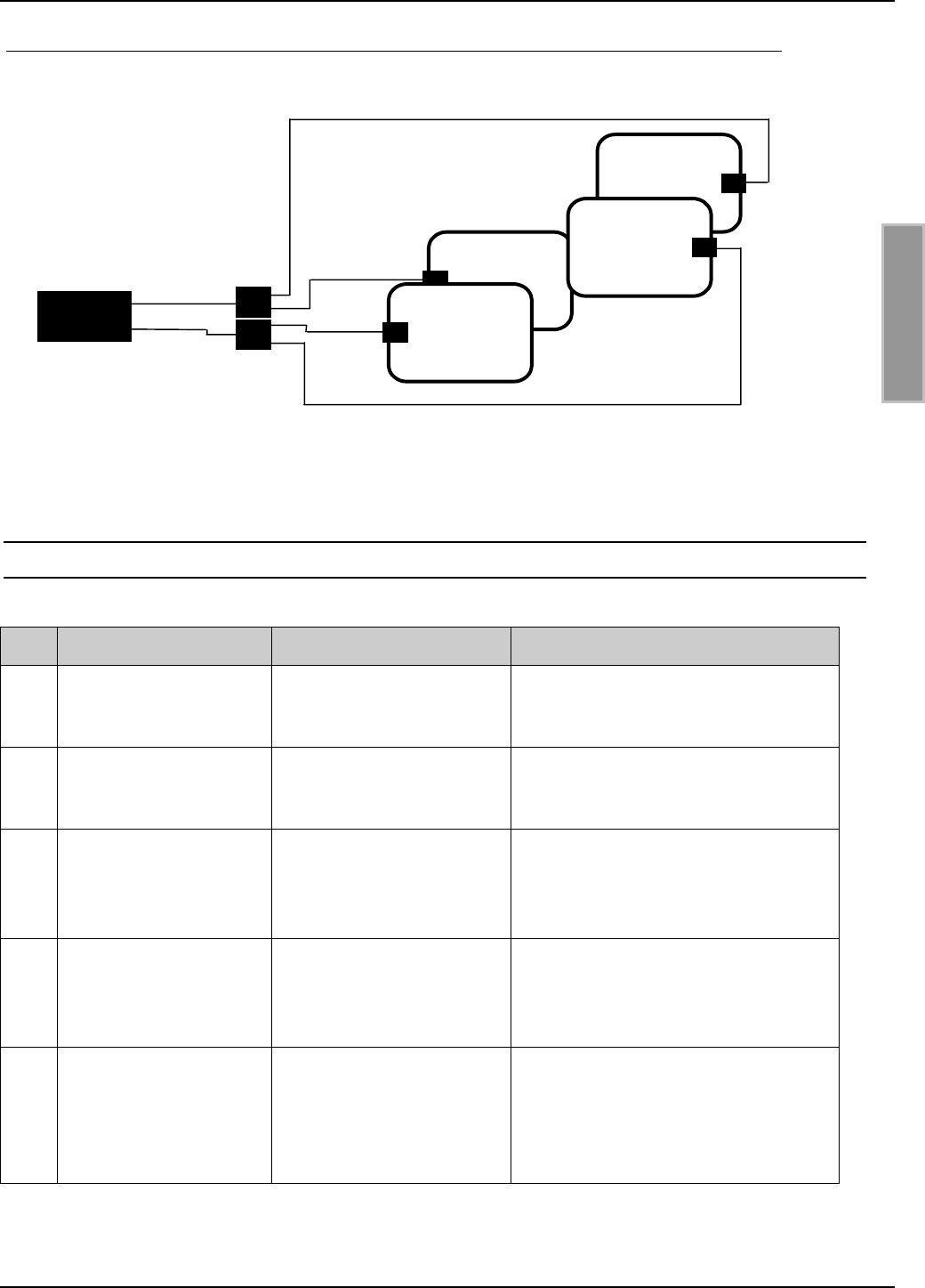
5. Mögliche Geräteanordnungen mit der Antenne ID ISC.ANT800/600
An den Reader ID ISC.LR200 können abhängig von der Applikation verschiedene Antennenauf-
bauten angeschlossen werden. Einige Schaltungsbeispiele werden nachfolgend aufgeführt.
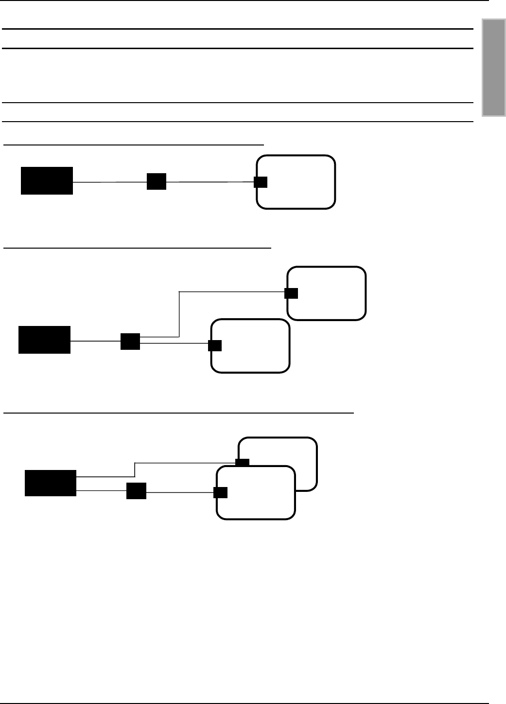
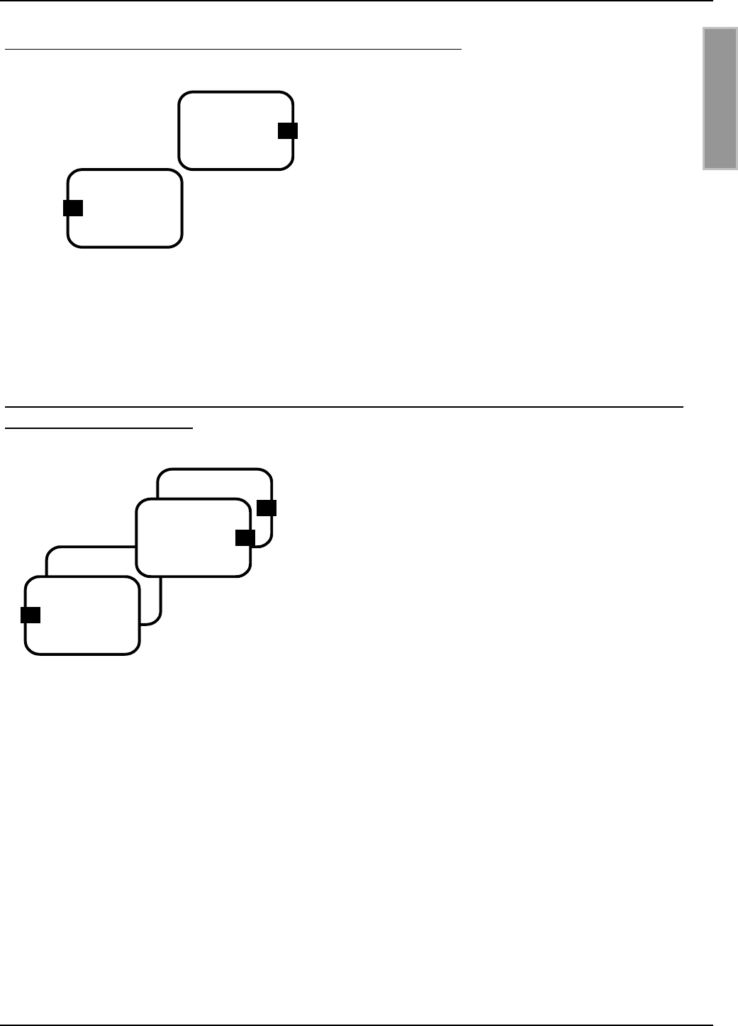
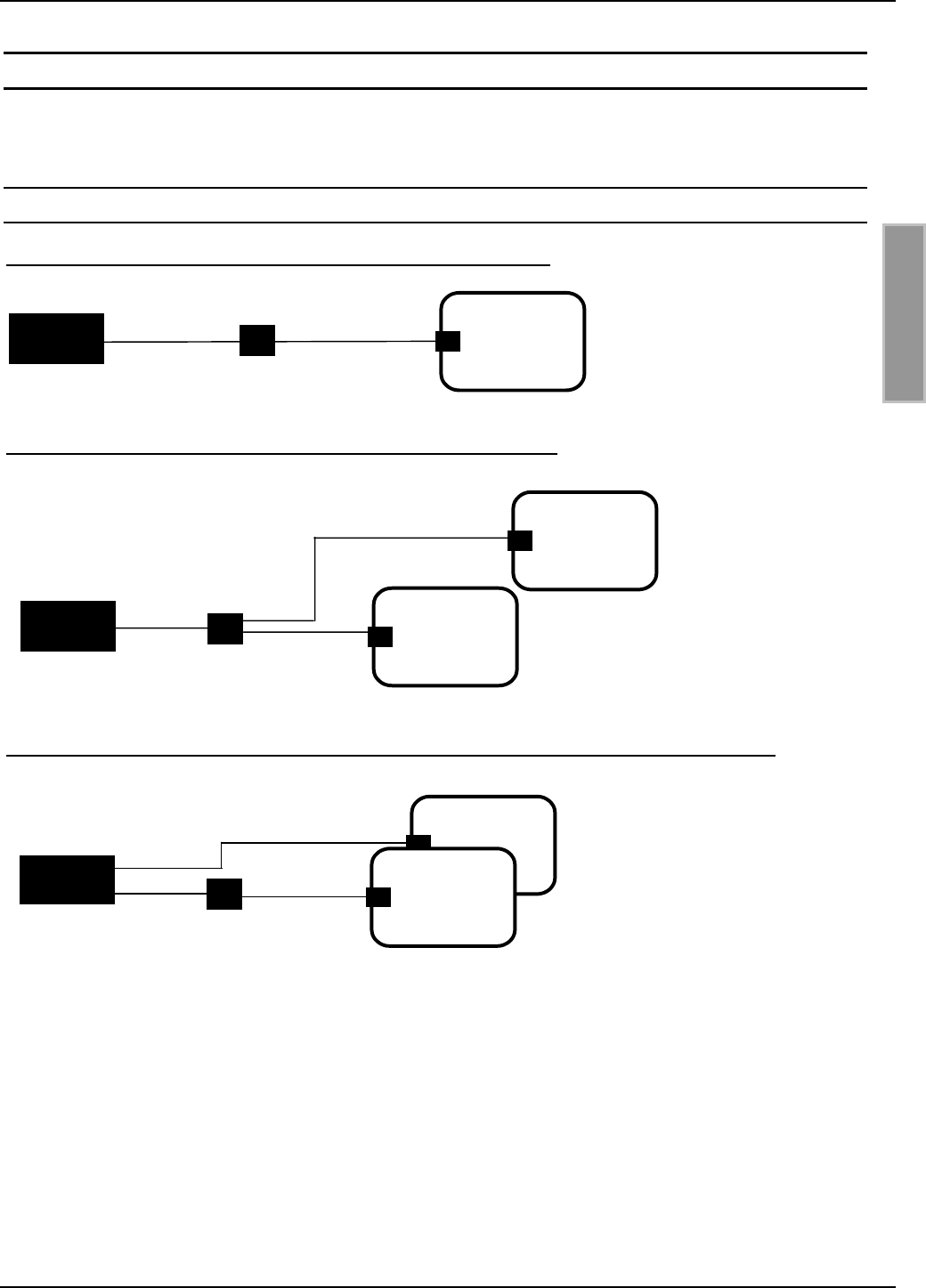
5.1.Mögliche Schaltungsbeispiele
Bild 1 Schaltskizze: Ein Reader und eine Basisantenne
Nur mit sehr geringen Leistungen innerhalb der gesetzlichen Funkvorschriften.
Bild 2 Schaltskizze: Ein Reader und zwei Basisantennen
Bild 3 Schaltskizze: Ein Reader, eine Basis- und eine Ergänzungsantenne
ID ISC.ANT.PS
ID ISC.ANT800/600-A
ID ISC.ANT800/600-A
Reade
r
ID ISC.ANT.T
ID ISC.ANT800/600-B
ID ISC.ANT800/600-A
Reade
r
Reade
r
ID ISC.ANT.T
ID ISC.ANT800/600-A
OBID® i-scan Montage ID ISC.ANT800/600
FEIG ELECTRONIC GmbH Seite 11 von 75 M01004-2de-ID-B.doc
D E U T S C H
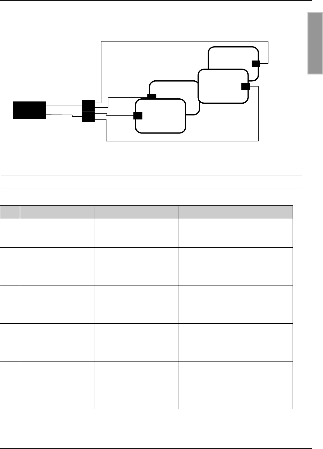
Bild 4 Schaltskizze: Ein Reader, zwei Basis- und zwei Ergänzungsantennen
5.2. Typische Antennenaufbauten
Nr Typ Benötigte Geräte Applikation
1 Ein Reader und eine
Basisantenne
1 x ID ISC.LR200-A
1 x ID ISC.ANT.T-A
1 x ID ISC.ANT800/600-A
Einfache Applikationen mit einer
Leserichtung b.z.w. Labelorientie-
rung bis 50 cm Reichweite
2 Ein Reader und zwei
Basisantennen
1 x ID ISC.LR200-A
1 x ID ISC.ANT.PS-A
2 x ID ISC.ANT800/600-A
Gate Applikationen mit großen Ga-
tebreiten und einer oder zwei Lese-
richtungen bzw. Labelorientierun-
gen
3 Ein Reader und zwei
Basisantennen in fest-
gelegter Montageposi-
tion
1 x ID ISC.LR200-A
1 x ID ISC.ANT.PS-A
2 x ID ISC.ANT800/600-A
Einfache Applikationen mit einer
Leserichtung bzw. Labelorientierun-
gen bis 80 cm Reichweite. Funkzu-
lassung ohne Abschirmung möglich.
4 Ein Reader und eine
Basis- und eine Er-
gänzungsantenne
1 x ID ISC.LR200-B
1 x ID ISC.ANT.T-A
1 x ID ISC.ANT800/600-A
1 x ID ISC.ANT800/600-B
Gate Applikationen bis zu 1 m und 2
oder 3 Leserichtungen bzw. Label-
orientierungen. Teilweise mit Funk-
zulassung möglich (mit Schirmung).
5 Ein Reader und zwei
Basis- und zwei Er-
gänzungsantennen
1 x ID ISC.LR200-B
2 x ID ISC.ANT.PS-A
2 x ID ISC.ANT800/600-A
2 x ID ISC.ANT800/600-B
Gate Applikationen mit 2 Gates
hintereinander bis zu 1 m Ga-
tebreite , großen Lesefenstern und
3 Leserichtungen bzw. Labelorien-
tierungen. Funkzulassung möglich.
2 x ID ISC.ANT.PS
2 x ID ISC.ANT800/600-B
2 x ID ISC.ANT800/600-A
Reade
r

OBID® i-scan Montage ID ISC.ANT800/600
FEIG ELECTRONIC GmbH Seite 12 von 75 M01004-2de-ID-B.doc
D E U T S C H
5.3. Zur Inbetriebnahme benötigte Komponenten
• 1 Stück ID ISC.SATC-A Static Antenna Tunning Controller
• Servicesoftware ISCStart ab Version 4.02 auf einem PC mit MS Windows Betriebssystem. Die
Software ISCStart finden Sie auf der OBID® i-scan CD der Firma FEIG ELECTRONIC GmbH.
• 1 Stück SWR Meter mit SMA Buchsen oder Adapter zu SMA–Buchsen.
• 1 Stück Kabel RG 58 C/U ca. 20 – 25 cm lang mit zwei SMA Stecker.
• 1 Stück Bernstein Schraubendreher.
• 1 Stück Oszilloskop. (Abgleich der Antennen ID ISC.ANT800/600 Type B)
• 2 Stück Meßschleifen. (Abgleich der Antennen ID ISC.ANT800/600 Type B)
Genauere Angaben zu den Geräten entnehmen Sie bitte der Gerätebeschreibung oder dem 10.
Anhang A Hilfreiche Werkzeuge für den Aufbau und Test der Antennen
OBID® i-scan Montage ID ISC.ANT800/600
FEIG ELECTRONIC GmbH Seite 13 von 75 M01004-2de-ID-B.doc
D E U T S C H
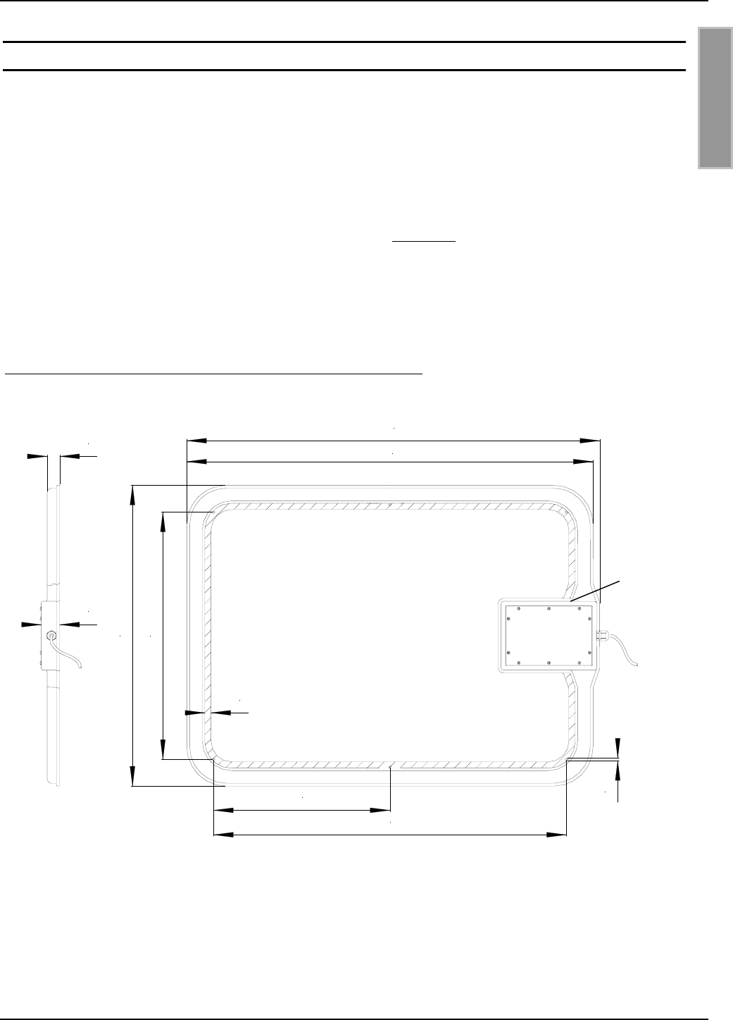
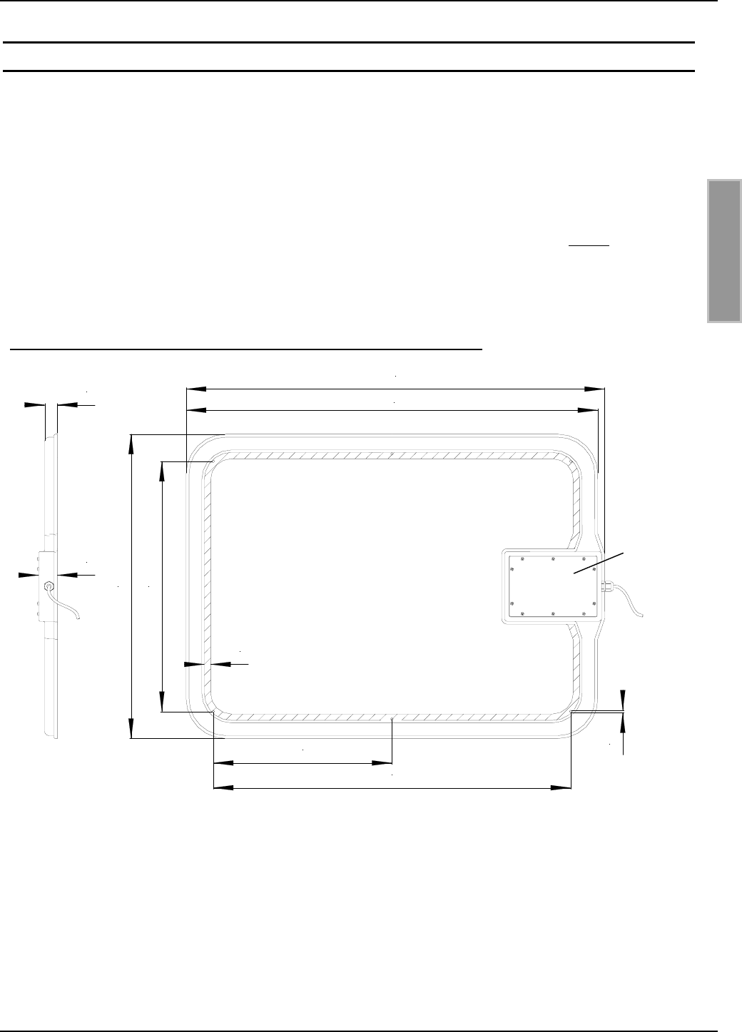
6. Montage und Anschluß
Die Antennen ID ISC.ANT800/600 Type A und B sind für die Montage an Halterungen aus nicht
leitenden Materialien (z.B. Kunststoff oder Holz) sowohl für den Innen- wie auch den Außenbereich
konzipiert. Zur Befestigung der Antenne befinden sich im Innenbereich der Antenne 6 Bohrungen
(d=5,4 mm). Abstand: Siehe Bild 5. Zur Montage empfehlen wir eine 5 mm Holzschraube (DIN 96)
oder eine Maschinenschraube (DIN 7985) mit einem Kopfdurchmesser von mindestens 10 mm bis
maximal 12 mm. Das maximale Anzugsmoment für freidrehende Schrauben beträgt 2,0 Nm.
Reichen die vorhandenen Bohrungen nicht aus, können innerhalb des schraffierten Bereichs, wei-
tere Löcher (d=5,4 mm) gebohrt werden.
Die Antenne muß einen Mindestabstand von 10 cm von eventuellen Metallteilen haben! Ab
50 cm Abstand zu Metallteilen muß mit Einbußen in der Lesereichweite gerechnet werden.
Bild 5: Montagezeichnung ID ISC.ANT800/600 Type A und B
Alle Maße in mm
Zum Abgleichen der Antenne muß der Deckel über der Antennenöffnung entfernt werden. Das
Anzugsmoment der Deckelschrauben beim Verschließen der Antenne beträgt 0,2 Nm – 0,25 Nm.
Werden mehrere Antennen nebeneinander montiert, sollten alle Antennen so befestigt werden,
daß die Deckel von einer Seite geöffnet werden können.
Antennenöffnung
(Deckel)
510
38
26
620±1
5,4
13
852±1
728
364
838±1
OBID® i-scan Montage ID ISC.ANT800/600
FEIG ELECTRONIC GmbH Seite 14 von 75 M01004-2de-ID-B.doc
D E U T S C H
Bild 6: Montageskizze Ansicht von oben
Wird ein Gate mit einer/zwei Basis- und einer/zwei Ergänzungsantenne aufgebaut, so sollten die
Antennenöffnungen/Deckel alle nach außen (vom Gate weg) oder alle zur Gatemitte zeigen. Wei-
terhin müssen die Deckel nach rechts und links angeordnet werden (Siehe Bild 6).
Die Antennen werden mit Hilfe des Anschlußkabels (siehe 5.1.Mögliche Schaltungsbeispiele) und
einem SMA- Stecker direkt an den Reader angeschlossen. Um Störungen in industriellen Umge-
bungen zu unterdrücken empfehlen wir zusätzlich das Gerät ID ISC.ANT.T Antenna Transformer
zwischen Reader und Basisantenne zu schalten.
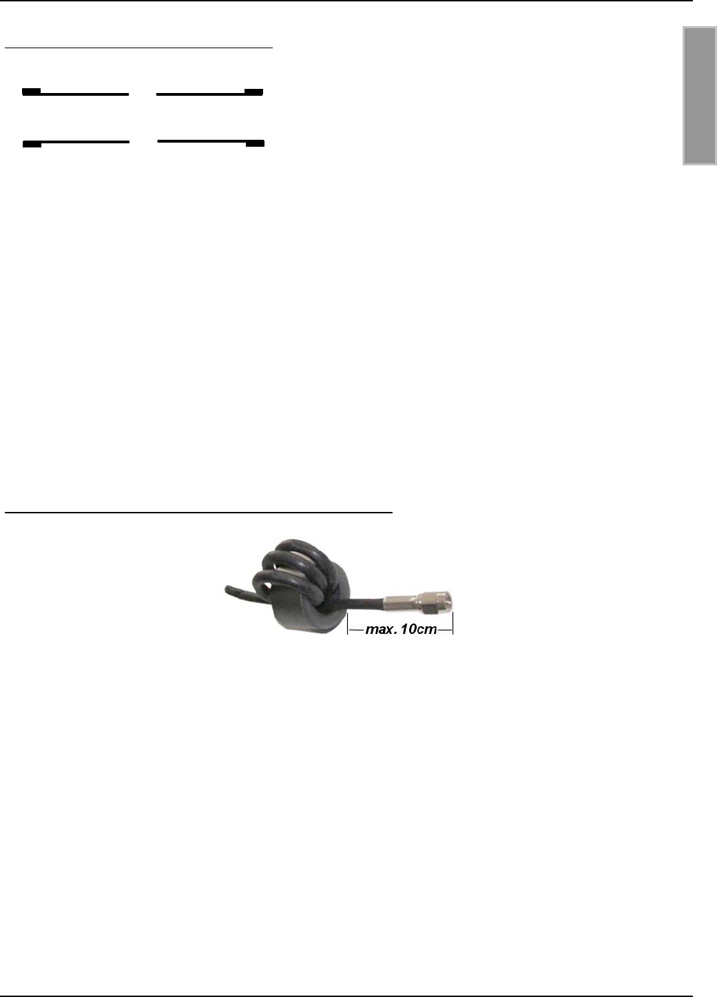
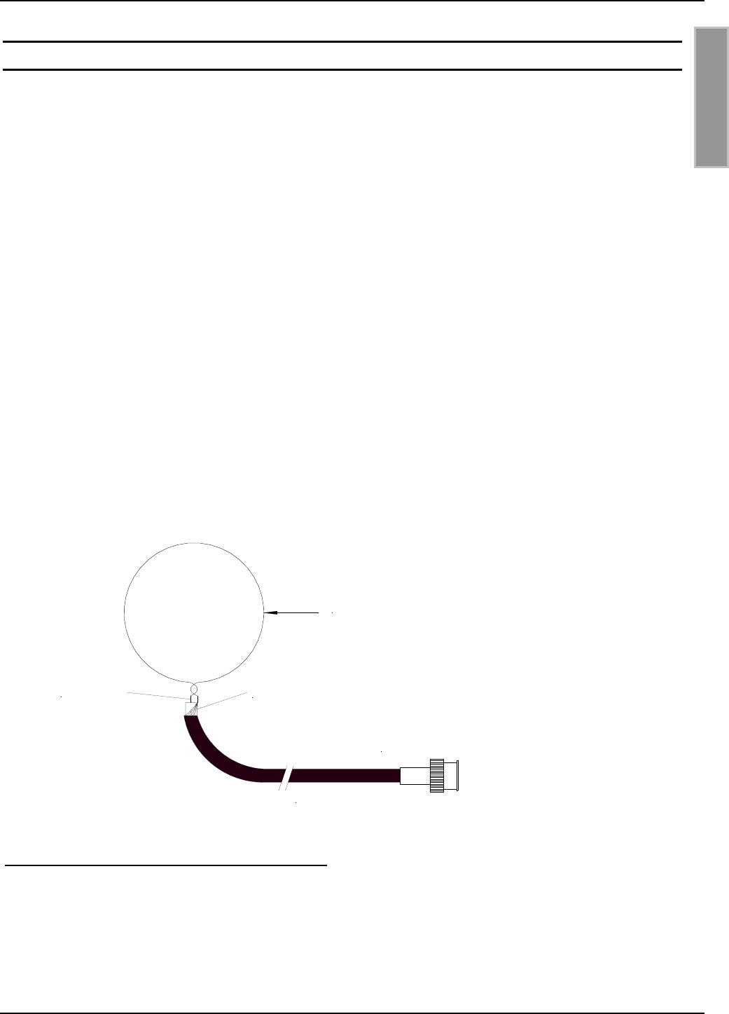
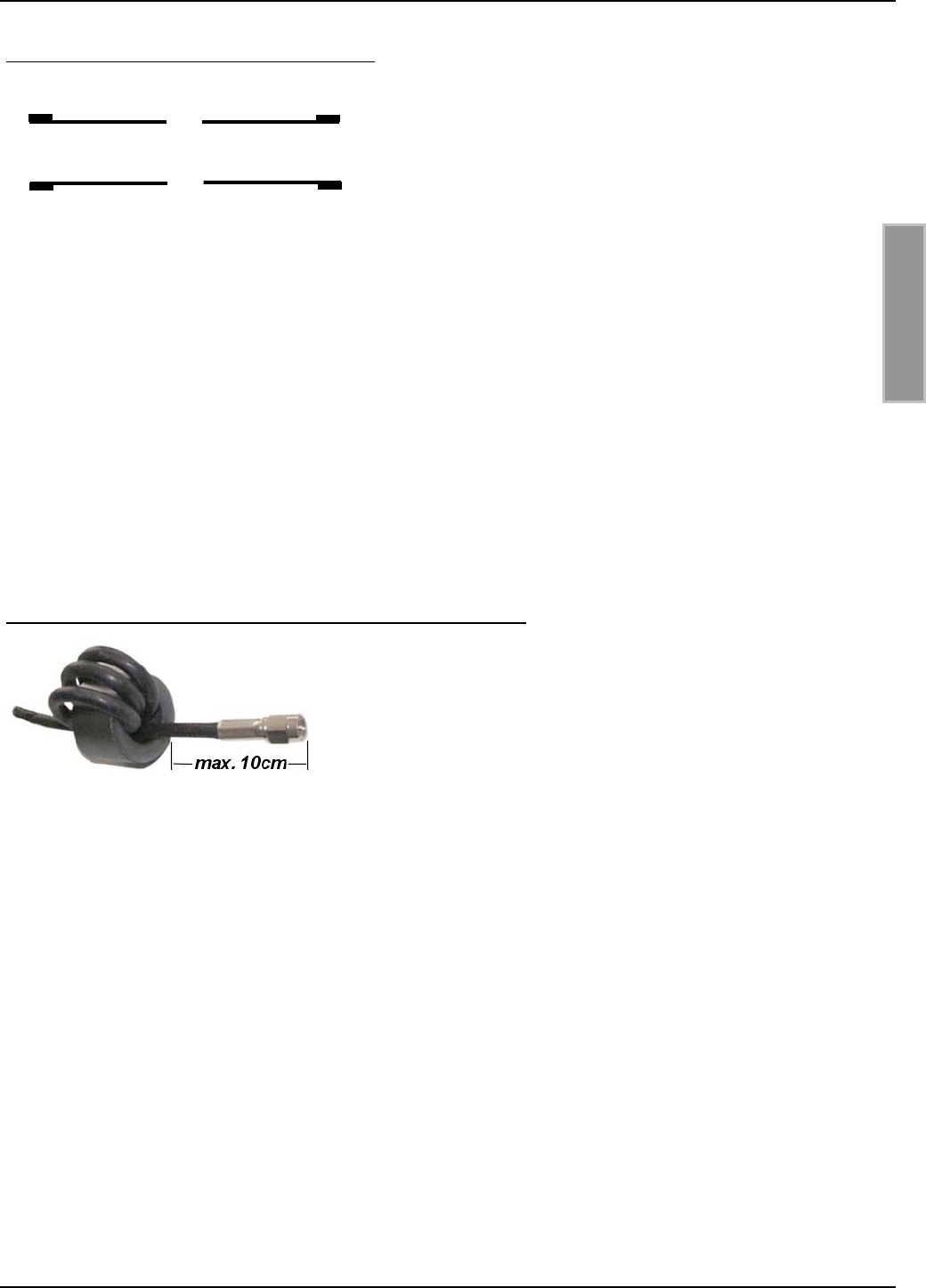
Um mögliche Störungen zu unterdrücken, werden dem Reader ID ISC.LR200 2 Ringkerne
∅ 28 mm x 20 mm beigelegt. Diese sollten in die Antennenanschlußkabel der Basis- und Ergän-
zungsantenne eingebaut werden. Dafür ist das Koaxial - Kabel mindestens vier mal, eng anliegend
durch den EMV - Ringkern zu schleifen. Der Abstand zwischen Readeranschluß und Ringkern
sollte dabei maximal 10 cm betragen.
Bild 7: Montage des Ringkerns auf der Antennenzuleitung
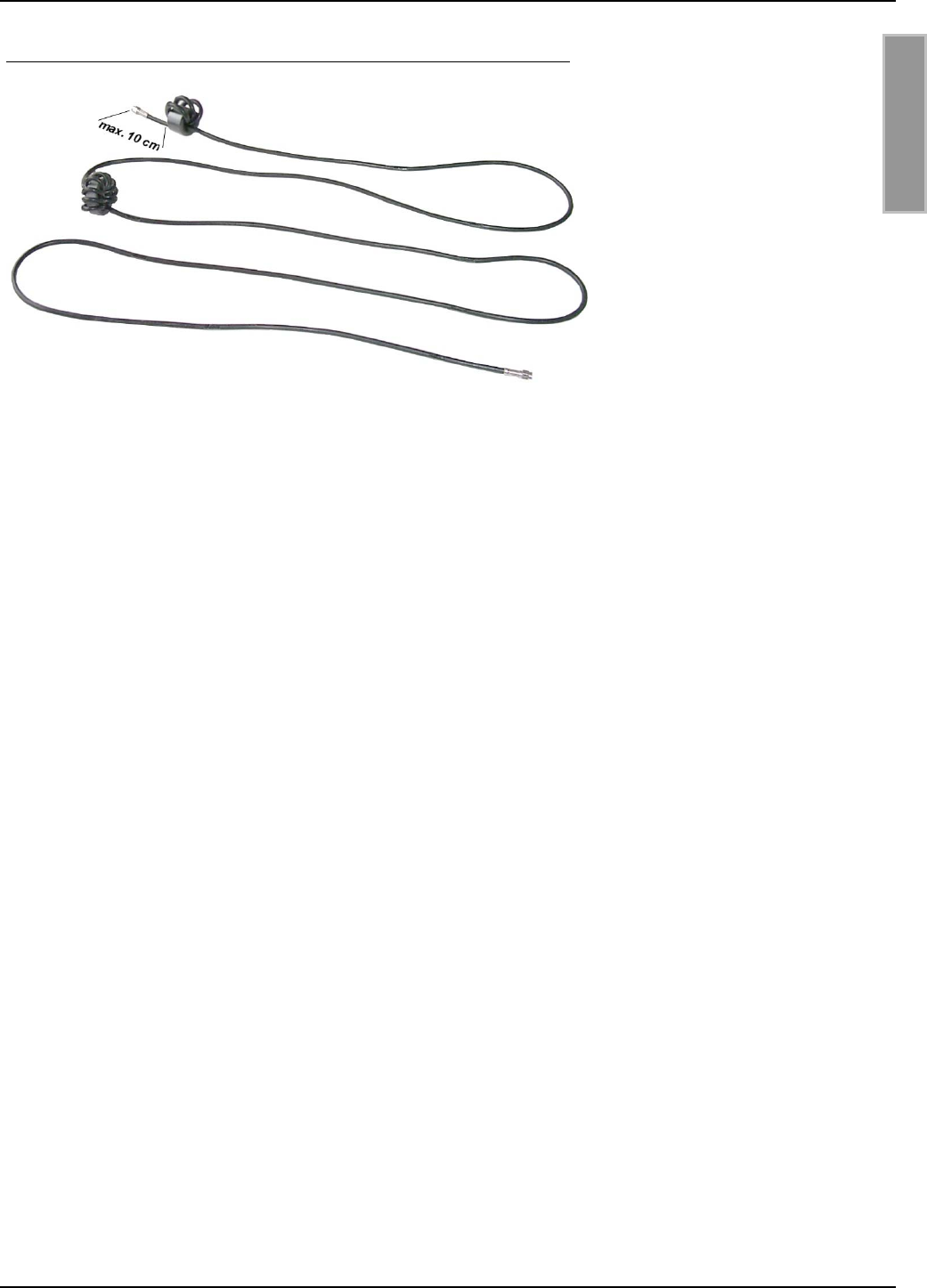
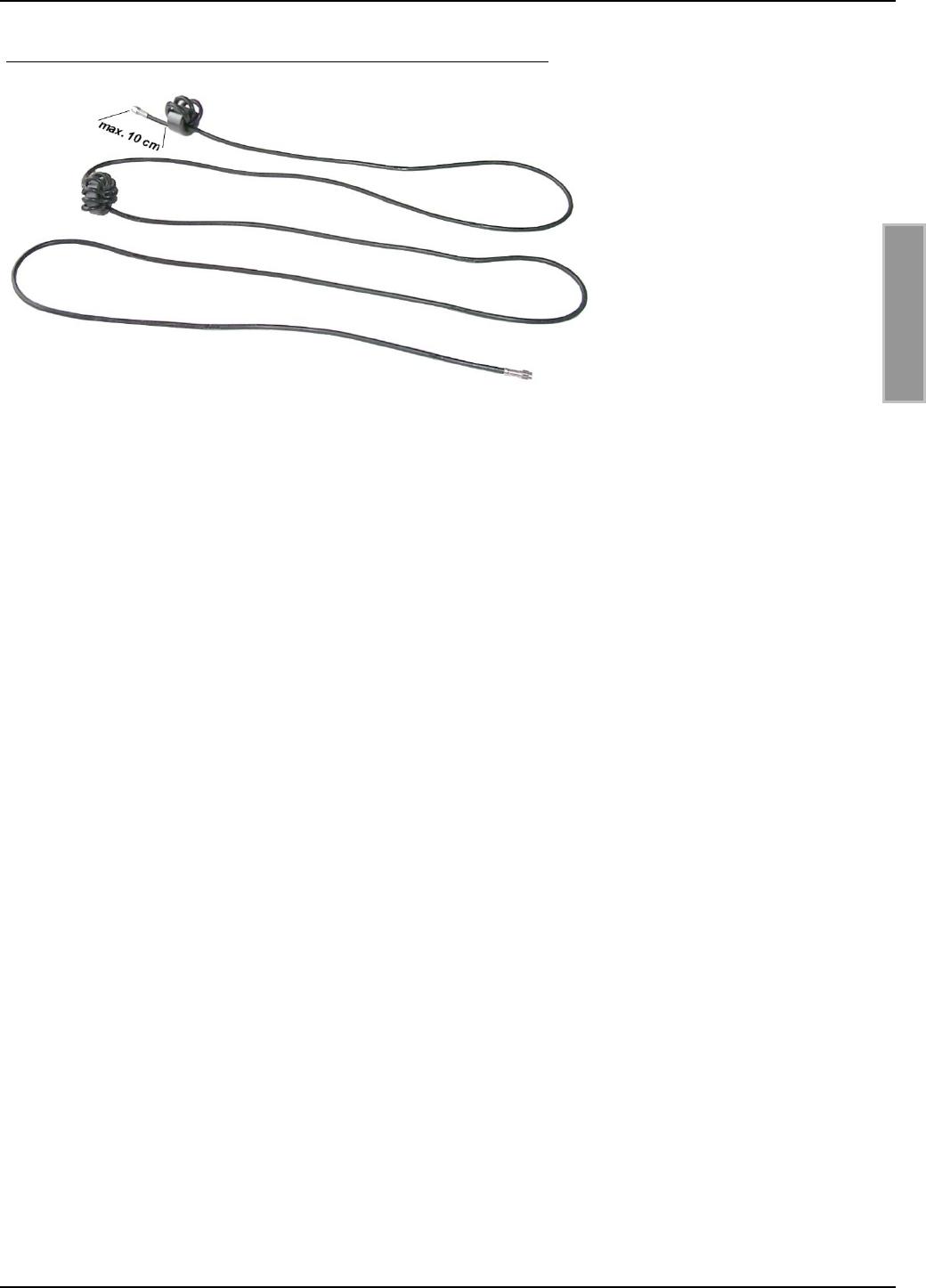
Um EMV Vorschriften in der USA nach FCC Part 15 einzuhalten, müssen in die Anschlußkabel der
Antennen ID ISC.ANT800/600 Typ A und B zwei Ringkerne wie in Bild 8 skizziert eingebaut wer-
den.
Der dem Reader beigelegte EMV - Ringkern ∅ 28 mm x 20 mm ist am Anfang des Kabels einzu-
bauen. Dafür ist die Antennenzuleitung mindestens vier mal, eng anliegend durch den Ringkern zu
schleifen. Der Abstand zwischen Readeranschluß und Ringkern sollte dabei maximal 10 cm betra-
gen.
Der EMV - Ringkern ∅ 41 mm x 15 mm ist genau in der Mitte des Antennenkabels zu montieren.
Dafür ist das Koaxial – Kabel mindestens zehn mal, eng anliegend durch den Ringkern zu schlei-
fen. Dieser Ringkerne sind den Antennen beigelegt.
OBID® i-scan Montage ID ISC.ANT800/600
FEIG ELECTRONIC GmbH Seite 15 von 75 M01004-2de-ID-B.doc
D E U T S C H
Bild 8: Montage der beiden Ringkerne auf der Antennenzuleitung
Nach der Montage kann die korrekte Funktion der Basisantenne ID ISC.ANT800/600-A mit Hilfe
des Readers und eines Smart Labels geprüft werden. Bei einer Sendeleistung von 4,0 W und einer
Labelgröße von 70 x 54 mm (ISO-Kartengröße) sollte die Lesereichweite in der Mitte der Basisan-
tenne bei ca. 80 cm liegen.
Wurde ein Gate mit Basis- und Ergänzungsantenne aufgebaut, kann die korrekte Funktion der
Basisantenne ID ISC.ANT800/600-A und der Ergänzungsantenne ID ISC.ANT800/600-B mit Hilfe
des Readers und einem Smart Label überprüft werden. Dafür müssen beide Antennen bei einer
Sendeleistung von 4,0 W, einer Labelgröße von 46 x 75 mm2 (ISO-Kartengröße), einer Gatebreite
von 1 m und einer Labelausrichtung parallel zur Antenne nach außen (außerhalb vom Gate) eine
Lesereichweite von 70-80 cm erreichen.
Andernfalls sollte die Anpassung der Basisantenne an die Impedanz von 50 Ω mit Hilfe eines SWR
– Meters, sowie die Rauschwerte (Noise Level) am Reader überprüft werden. Die Überprüfung der
Funktion der Ergänzungsantenne ist in 8.7. Messen des Phasenwinkel und Überprüfung der Strö-
me in der Antenne beschrieben.
Werden mehrere Antennen ID ISC.ANT800/600 oder Gates an verschiedenen Readern ange-
schlossen, muß ein Mindestabstand von 10 m zwischen den Antennen oder Gates eingehalten
werden. Andernfalls ist ein Multiplexen der Reader notwendig.
Achtung: Am Antennenleiter oder an verschiedenen Bauteilen der Abgleichplatinen können
Spannungen bis zu 1000V auftreten. Vor dem Beginn der Arbeiten muß die Antenne vom
Reader getrennt werden. Beim Aufstecken des Controllers ID ISC.SATC-A auf die Antenne
ist darauf zu achten, daß keine Bauteile innerhalb des Gehäuse berührt werden.
OBID® i-scan Montage ID ISC.ANT800/600
FEIG ELECTRONIC GmbH Seite 16 von 75 M01004-2de-ID-B.doc
D E U T S C H
6.1. Hinweise zur Kabelführung der Antennenzuleitung
Bei der Kabelführung bzw. beim Aufbau von Einzelantennen oder Antennen Gates ist auf folgen-
des zu achten:
• Das Antennenkabel ist immer vor dem Abgleichen fest zu verlegen. Bei späteren Änderungen
sollten mit den Oszilloskope die Phase und Amplitude der Ströme kontrolliert werden.
• Bis zu einem Abstand von 50 cm sollte das Antennenkabel immer senkrecht von der Antenne
weg geführt werden.
• Muß das Antennenkabel näher an der Antenne entlang verlegt werden, so sind mindestens
20 cm Abstand einzuhalten.
• Ein Verlegen des Antennenkabel durch die Antenne ist immer ungünstig. Falls sich dies nicht
Vermeiden läßt darf das Antennenkabel nur im Winkel von 90 Grad zum Abgleich, zum gege-
nüberliegenden Antennenrohr in der Mitte der Antenne verlegt werden.
• Um optimale Lesereichweiten zu erzielen sollte das Antennenanschlußkabel nicht verkürzt oder
verlängert werden. Ist eine Verlängerung zwingend erforderlich, so kann dies mit einem 50 Ω
Kabel in der Länge 2
λ
(halbe Wellenlänge bei 13,56 MHz, RG58=7,20 m) durchgeführt wer-
den. Dabei ist mit geringen Empfindlichkeitsverlusten zu rechnen.
• Das Antennenkabel muß einen Abstand von wenigstens 30 cm zu parallel geführten stromfüh-
renden Leitungen haben.
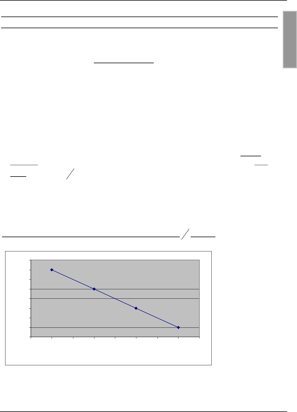
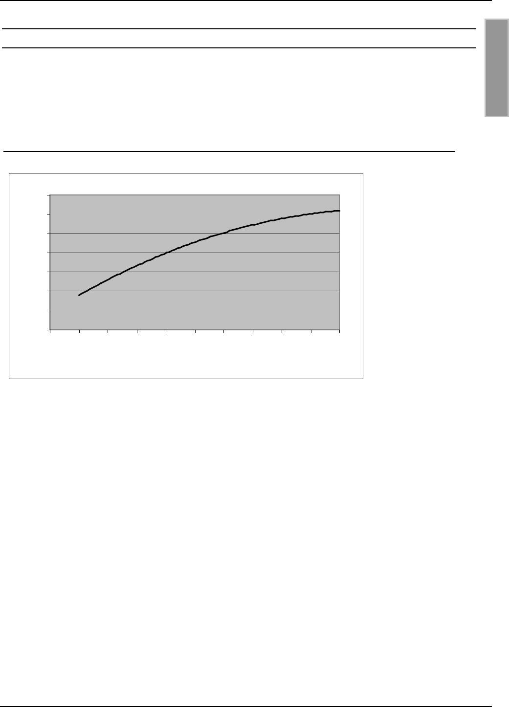
Bild 9: Lesereichweite* in Abhänigkeit der Antennenzuleitung in 2
λ
Schritten
*Label 46 x 75 mm2 über der Antennen Mitte, Empfindlichkeit / Minimale Feldstärke Hmin=85mA/m
rms, parallele Ausrichtung des Labels zur Antenne. Sendeleistung 4 W
73
74
75
76
77
78
79
80
81
0 3,62 7,24 10,86 14,48 18,1 21,72 25,34 28,96
Länge der Antennenzuleitung
Reichweite [cm]
OBID® i-scan Montage ID ISC.ANT800/600
FEIG ELECTRONIC GmbH Seite 17 von 75 M01004-2de-ID-B.doc
D E U T S C H
7. Der Abgleich der Antennen
Um die gültigen Funkvorschriften einzuhalten, ist bei einer eingestellten Sendeleistung von größer
1 W mindestens ein Aufbau aus zwei Basisantennen notwendig. Daher gehen wir hier von dieser
Standard Konfiguration aus.
Das Abgleichen eines Gates aus Basis- und Ergänzungsantenne wird in der Application Note
“Aufbau und Abgleich einer Gateantenne mit 1 m x 1 m Lesefenster in beliebiger Label –
Orientierung” beschrieben. Dateiname: N10900-2d-ID-B.pdf. Dieses Dokument finden Sie auf der
OBID® i-scan CD der Firma FEIG ELECTRONIC GmbH.
Der Abgleich eines Gates aus vier Basisantennen wird in der Application Note “ Aufbau und Ab-
gleich einer Gateantenne aus vier Basisantennen“ beschrieben. Dateinamen: N11000-2d-ID-B.pdf.
Dieses Dokument finden Sie auf der OBID® i-scan CD der Firma FEIG ELECTRONIC GmbH.
Vor dem Abgleichen der Basis- oder Ergänzungsantenne müssen die Antennen und Antennenka-
bel fest montiert werden. Die Geräte ID ISC.ANT.T-A Transformer und ID ISC.ANT.PS-A Power
Splitter werden erst nach dem Abgleich der Antennen eingebaut.
Zum Abgleichen der Antenne muß der Deckel über der Antennenöffnung entfernt werden. Das
Anzugsmoment der Deckelschrauben beim Verschließen der Antenne beträgt 0,2 Nm – 0,25 Nm.
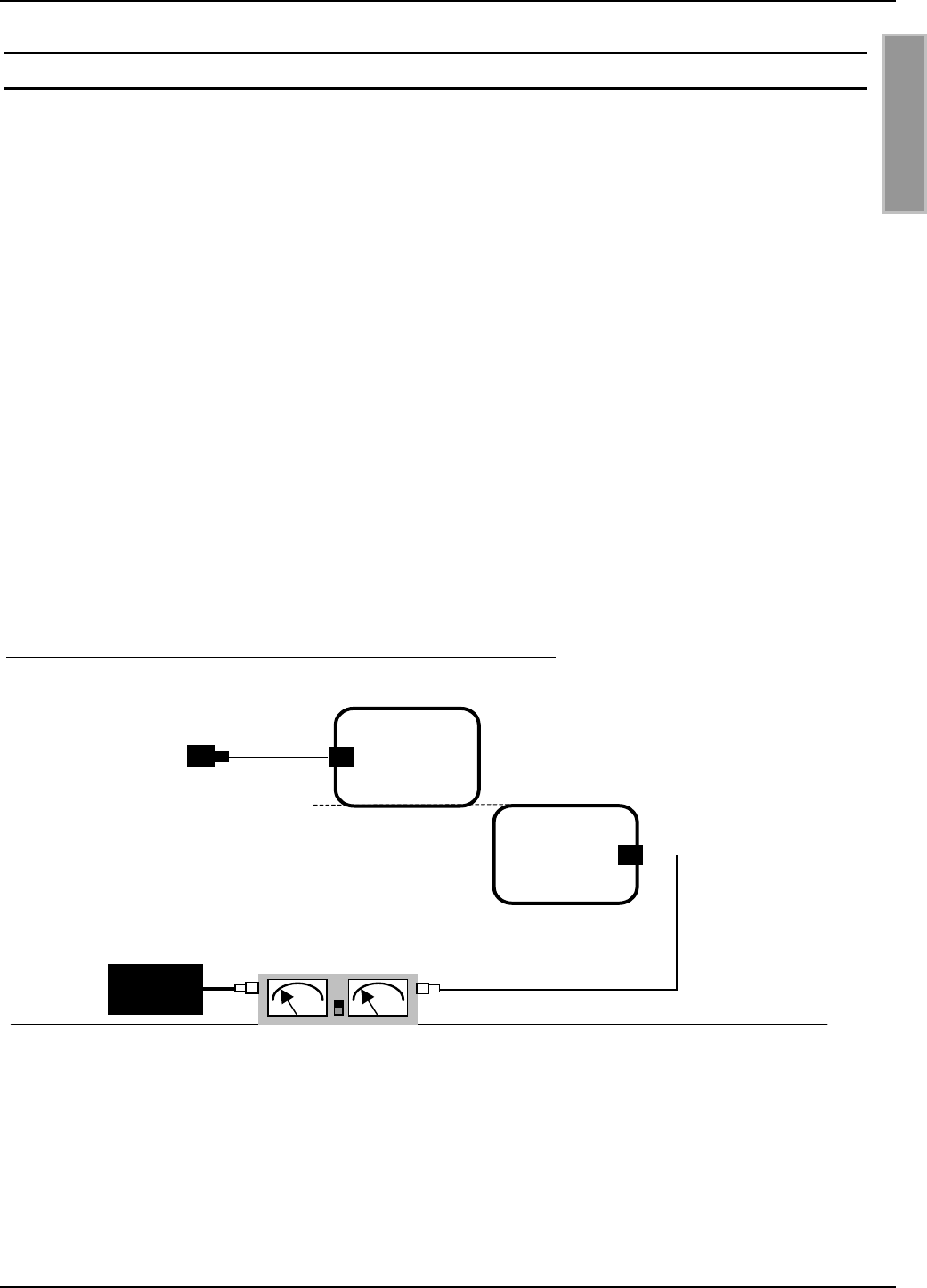
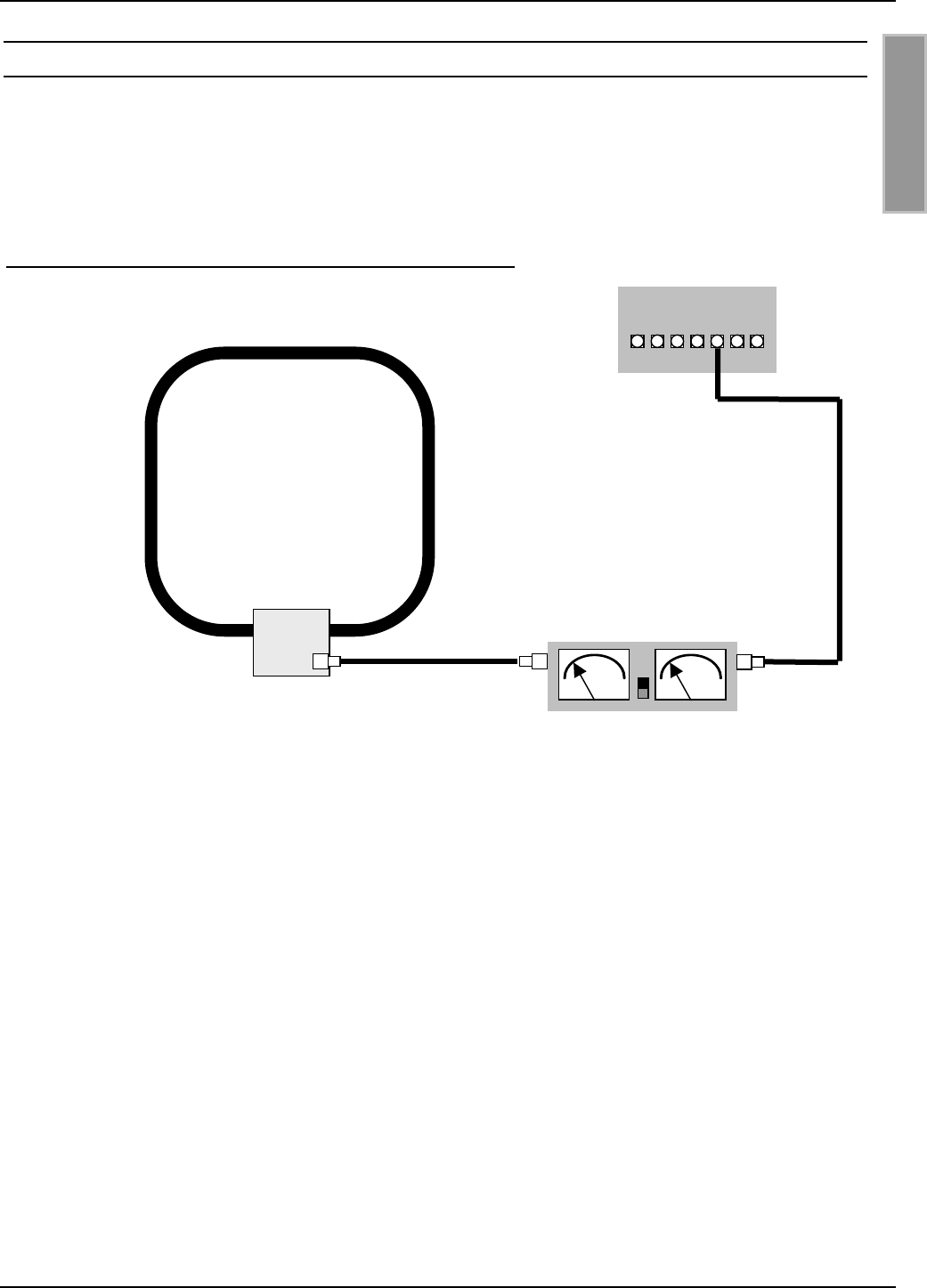
Anschließend wird die erste Basisantenne über das SWR-Meter mit dem Reader Anschluß X2
verbunden. Die zweite Antenne ist mit einem Abschlußwiderstand von 50 Ω abzuschließen.
Bild 10: Konfiguration zum Abgleichen der ersten Basisantenne
Der Abgleichvorgang beginnt mit der ersten Basisantenne. Anschließend ist die zweite Antennen
abzugleichen. Da sich die beiden benachbarten Basisantennen gegenseitig beeinflussen, muß die
erste Basisantenne danach noch einmal abgeglichen werden.
2 x ID ISC.ANT800/600-A
ID ISC.LR200-A
50 Ω Abschlußwiderstand
Antenne 1
Antenne 2
SWR - Meter
OBID® i-scan Montage ID ISC.ANT800/600
FEIG ELECTRONIC GmbH Seite 18 von 75 M01004-2de-ID-B.doc
D E U T S C H
7.1. Vorbereitungen
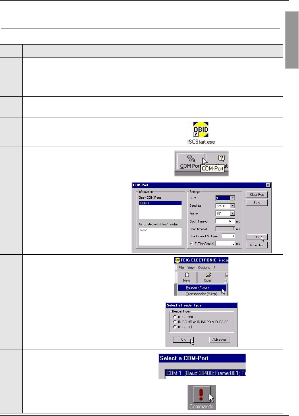
Step Vorgang Hinweis
1Verbinden Sie den Reader
ID ISC.LR200 über die Schnitt-
stelle RS232 oder RS485 mit
dem PC
Siehe Installation Manual ID ISC.LR200
2Installieren Sie die Demo Soft-
ware ISCStart
Auf der OBID® i-scan CD
3Starten Sie das Programm
ISCStart
4Öffnen Sie die COM-Port Ein-
stellungen
5Überprüfen Sie die COM-Port
Einstellungen und bestätigen Sie
mit dem OK-Button
6Öffnen Sie nun das Menü File –
New – Reader
7Wählen Sie ID ISCLR und bes-
tätigen Sie mit OK
8Wählen Sie COM: x [Baud
38400......]
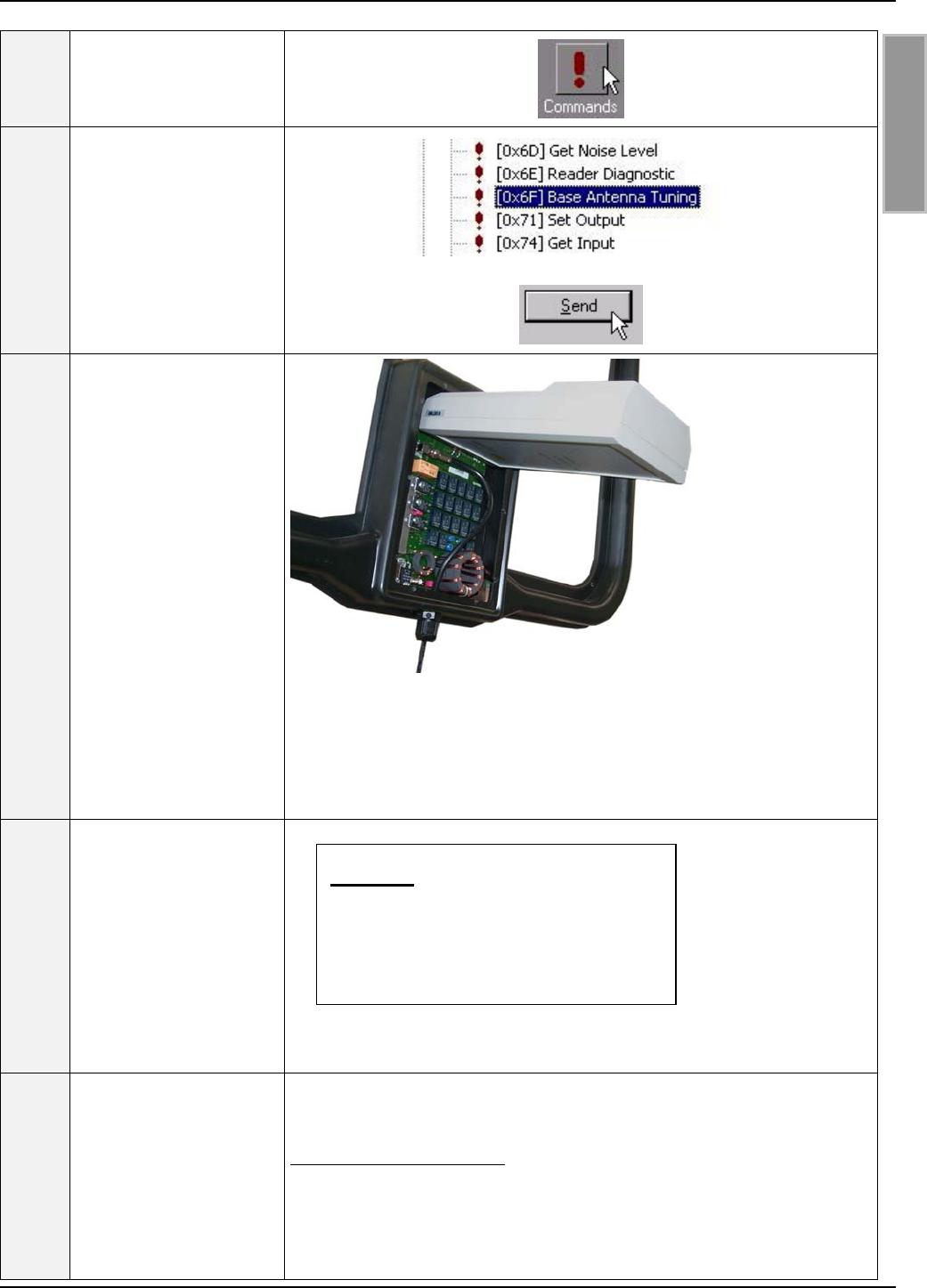
9Button Commands auswählen
OBID® i-scan Montage ID ISC.ANT800/600
FEIG ELECTRONIC GmbH Seite 19 von 75 M01004-2de-ID-B.doc
D E U T S C H
10 Befehl Baudrate Detetion
[0x52] wählen
11 Button Send auswählen
12 Das Programm testet alle mögli-
chen Baudraten. Es stoppt so-
bald die am Reader eingestellte
Baudrate erkannt wurde (Stan-
dard 38400 / 8E1) mit OK.
13 Button Configuration auswählen
14 Zeile ID ISCLR Configuration
wählen.
15 Ziel – Speicher EEPROM aus-
wählen.
16 Mit Button Reset [0x83] ist der
Reader auf die Standard Konfi-
guration einzustellen.
17 Mit dem Button Read wird die
Reader Konfiguration in den PC
bzw. das Programm ISCStart
geladen.
OBID® i-scan Montage ID ISC.ANT800/600
FEIG ELECTRONIC GmbH Seite 20 von 75 M01004-2de-ID-B.doc
D E U T S C H
7.2. Abgleich der Basisantenne
Die Basisantenne wurde im Werk an einer Holzplatte auf die Impedanz von 50 Ω abgestimmt. Wird
sie in der Nähe von Metall oder zusammen mit einer anderen Basis- oder Ergänzungsantenne
oder anderen magnetisch leitenden Stoffen montiert, ist ein Abgleichen oder Nachgleichen der
Antenne notwendig.
In diesem Fall sollte eine Kontrolle der Eingangsimpedanz (8.6. Das Messen des Stehwellenver-
hältnisses VSWR) durchgeführt werden.
Maßgeblich für die magnetische Feldstärke und somit auch für die Lesereichweite der Antenne
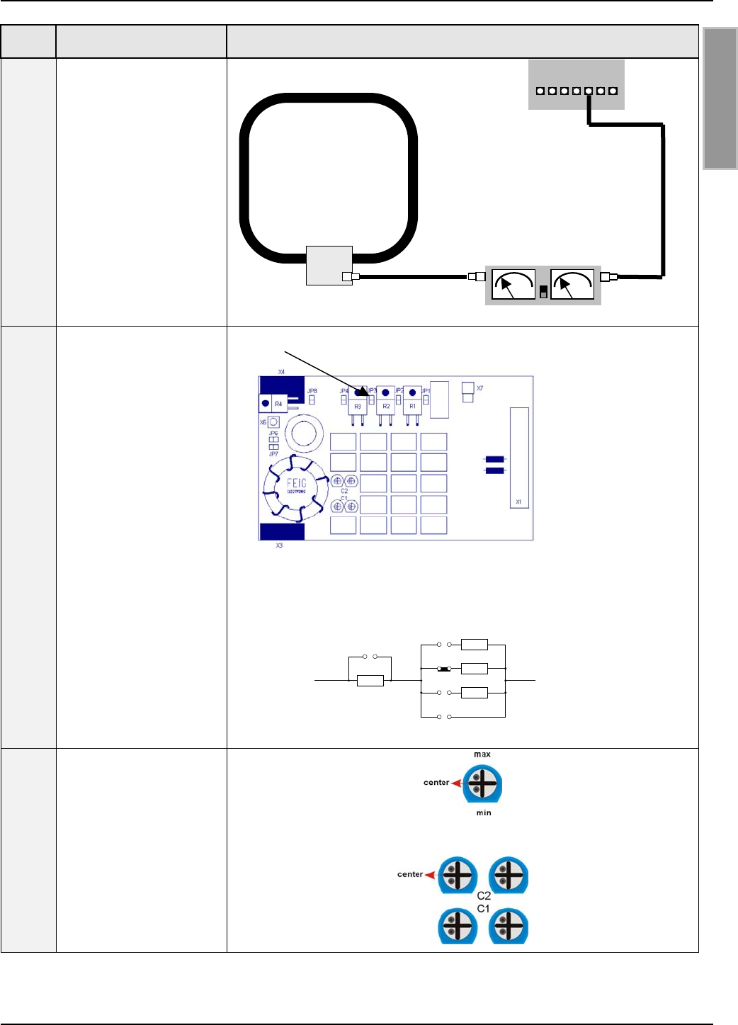
und die Einhaltung der Zulassungsvorschriften für Funkanlagen ist der Antennenstrom. Dieser wird
durch die Widerstände R1-R4 beeinflußt. Bei der Auslieferung der Antenne wurde ein Widerstand
von 3 Ω durch schließen der Brücke (Jumper) JP3 eingestellt.
Durch schließen oder öffnen der Brücken JP1-JP4 und JP8 kann der Widerstand angepaßt
werden. Den jeweiligen Wert des Gesamtwiderstands entnehmen Sie bitte aus folgender Tabelle.
Tabelle 1: Wert des Reihenwiderstand
Jumper Gesamtwiderstand R
JP8 offen JP8 geschlossen
JP1 geschlossen 2,0 Ω0 Ω
JP2 geschlossen 2,4 Ω0,4 Ω
JP3 geschlossen** 3,0 Ω1,0 Ω
JP4 geschlossen 4,0 Ω2,0 Ω
JP2 und JP3 geschlossen 2,28 Ω 0,28 Ω
JP2 und JP4 geschlossen 2,33 Ω 0,33 Ω
JP3 und JP4 geschlossen 2,66 Ω 0,66 Ω
JP2, JP3 und JP4 geschlossen 2,23 Ω 0,23 Ω
** Standart/Grundeinstellung.
Sind alle Jumper offen, so ist der Antennenkreis unterbrochen.
OBID® i-scan Montage ID ISC.ANT800/600
FEIG ELECTRONIC GmbH Seite 21 von 75 M01004-2de-ID-B.doc
D E U T S C H
Step Vorgang Hinweis
1
Verbinden Sie den
Reader über das SWR
Meter mit der Basis-
antenne.
Siehe auch Kapitel:
8.6. Das Messen des
Stehwellenverhältnis-
ses VSWR
2
Die Jumper JP1 – JP4
und JP6 –8 sind zu
kontrollieren bzw. ein-
zustellen.
Jumper JP6 + JP7 sind
im Betriebsfall und
während des Ab-
gleichs der Basisan-
tenne nicht gesteckt.
Weitere Einstellungen
für den Serienwider-
stand sind in der Ta-
belle 1 aufgeführt
Der Jumper JP3 muß gesteckt sein.
Standarteinstellung: JP1, JP2, JP4, JP6, JP7 und JP8 = offen
Rges = 3 Ω
3
Die Trimmkondensato-
ren C1 und C2 sind an
der Basisantenne in
Mittelstellung zu brin-
gen.
Basisantenne
ID ISC.
ANT800/600-A
SWR / Power Mete
r
Reader
ID ISC.LR200
JP8
JP4
JP3
JP2
JP1
2
Ω
2
Ω
1
Ω
0,4
Ω
OBID® i-scan Montage ID ISC.ANT800/600
FEIG ELECTRONIC GmbH Seite 22 von 75 M01004-2de-ID-B.doc
D E U T S C H
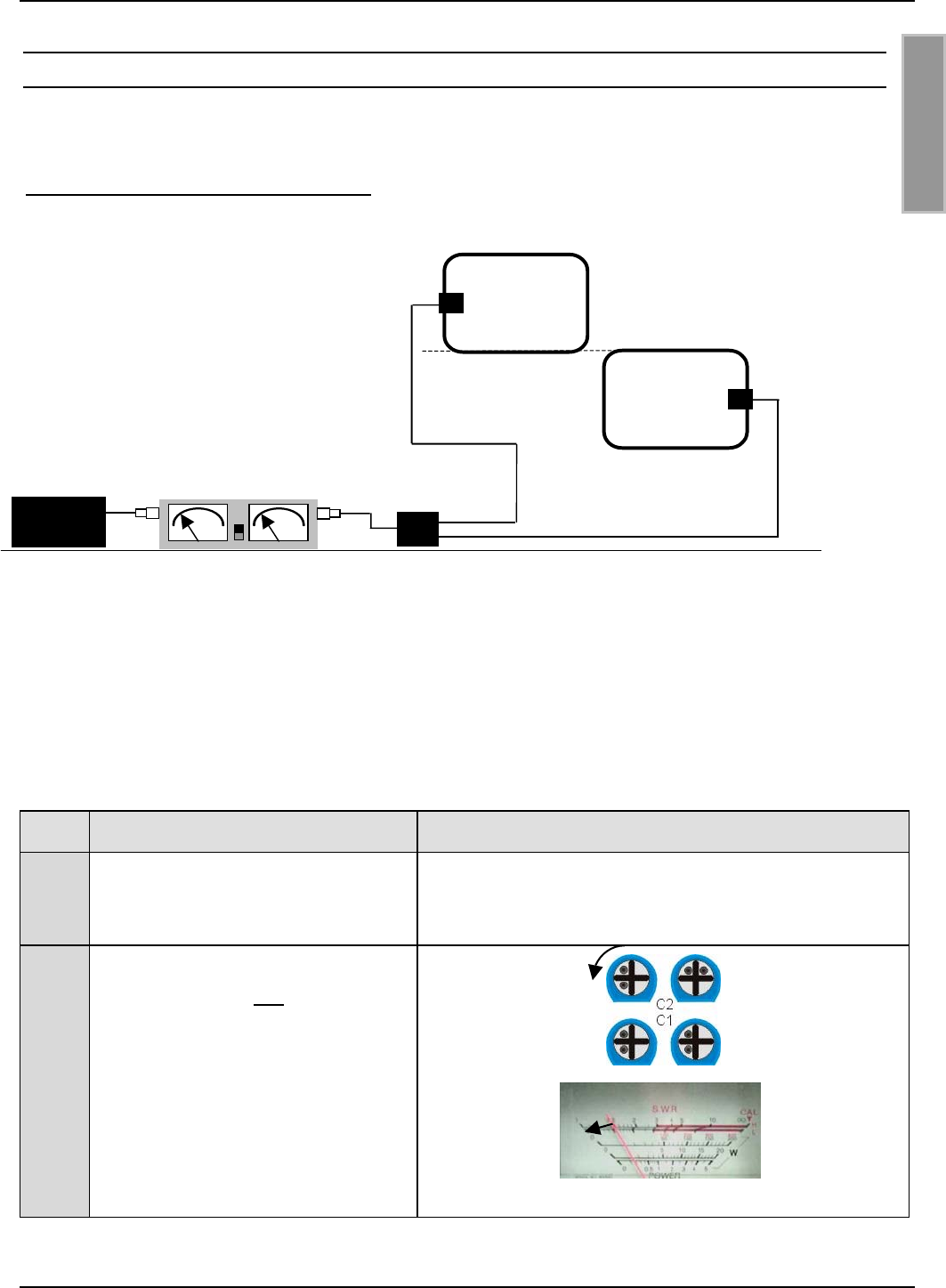
4Button Commands
auswählen
5
Befehl [0x6F] Base
Antenna Tunning
ausführen damit der
Reader in den Ab-
gleichmodus geschal-
tet wird.
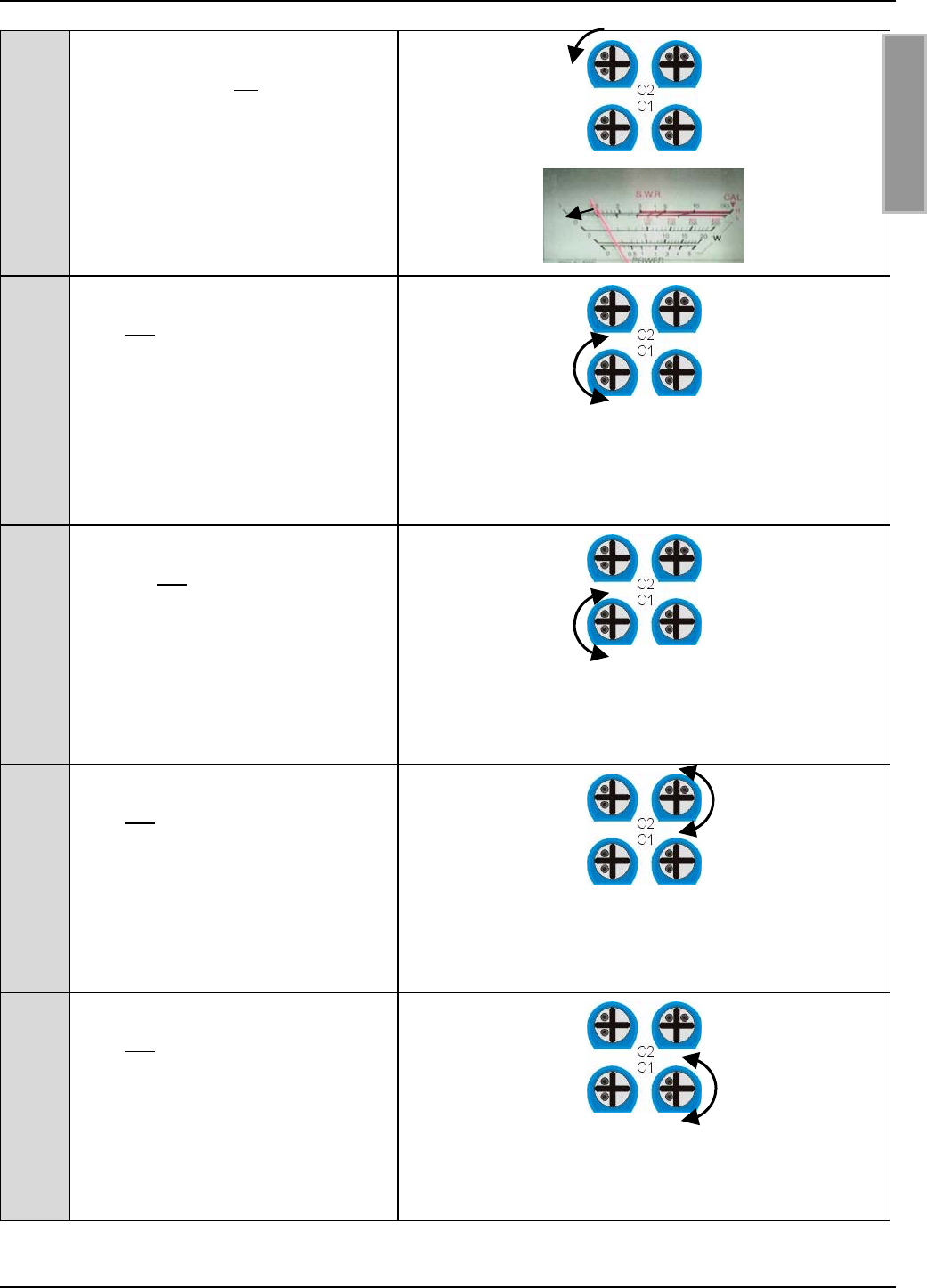
6
Stecken Sie jetzt den
Static Antenna Tuning
Controller
ID ISC.SAT.C-A an
den Antennentuner der
Basisantenne und drü-
cken Sie die Taste-
„Start“ am Controller.
Der Abgleichvorgang
dauert einige Sekun-
den und sollte durch
ein 4 Sekunden langes
Leuchten der grünen
LED abgeschlossen
werden.
.
Abgleichmodus: Wird aktiviert durch längeres Drücken der
Start Taste (> 2 Sekunden)
Kontrollmodus: Wird aktiviert durch kurzes Drücken der
Start Taste (< 2 Sekunden).
7
Danach schaltet sich
der Controller automa-
tisch ab und kann wie-
der abgezogen wer-
den.
Nun kann mit dem Abgleich der Ergänzungsantenne begon-
nen werden.
8
Wird der Abgleich nicht
ordnungsgemäß abge-
schlossen, so wird dies
durch die rote LED
angezeigt.
Tritt ein Fehler am
Anfang des Abgleich-
Blinkt die rote LED für 4 Sekunden so liegt keine RF-Leistung an
der Antenne.
Mögliche Ursachen sind:
• Reader oder RF-Leistung ausgeschaltet
• Verbindungskabel zwischen Reader und Antenne defekt.
• Die SMA Stecker wurden nicht ordnungsgemäß am Reader
Wichtig:
Den Controller nicht vor dem
erlöschen der grünen LED ab-
ziehen!

OBID® i-scan Montage ID ISC.ANT800/600
FEIG ELECTRONIC GmbH Seite 23 von 75 M01004-2de-ID-B.doc
D E U T S C H
vorgangs auf, so
blinkt die LED für 4
Sekunden.
Tritt ein Fehler wäh-
rend oder am Ende
des Abgleichvorgangs
auf, so leuchtet die
LED für 4 Sekunden.
Leuchtet die gelbe
LED für 4 Sekunden,
sind die Batterien im
Controller leer und
müssen ausgetauscht
werden.
und den Antennen montiert und sitzen nicht sicher auf den
SMA-Buchsen.
• Das Kabel ist nicht ordnungsgemäß auf die SMA Stecker ge-
quetscht.
• Controller wurde nicht richtig auf die Platine gesteckt.
Leuchtet die rote LED für 4 Sekunden wurde der Abgleich nicht
ordnungsgemäß abgeschlossen
Mögliche Ursachen sind:
• Verbindungskabel zwischen Reader und Antenne defekt.
• Die SMA Stecker wurden nicht ordnungsgemäß am Reader
und den Antennen montiert und sitzen nicht sicher auf der
SMA-Buchsen.
• Das Kabel ist nicht ordnungsgemäß auf die SMA Stecker ge-
quetscht.
• Modulation am Reader eingeschaltet.
• Güte der Antenne zu hoch eingestellt.
• Controller wurde nicht richtig auf die Platine gesteckt.
• Tuner Platine defekt.
Nach dem Abgleich der Basisantennen sollte die korrekte Funktion der Antenne mit Hilfe des Rea-
ders und eines Smart Labels geprüft werden. Bei einer Sendeleistung von 4,0 W und einer Label-
größe von 46 x 75 mm2 (ISO-Kartengröße) sollte die Lesereichweite in der Mitte der Basisantenne
bei ca. 80 cm liegen.
Andernfalls sollte die Anpassung der Basisantenne an die Impedanz von 50 Ω wie unter 8.6. Das
Messen des Stehwellenverhältnisses VSWR beschrieben, sowie die Noise Level am Reader über-
prüft werden.
7.3. Der Abgleich der zweiten Basisantenne
Zum Abgleich der zweiten Basisantenne wird diese über das SWR - Meter mit dem Reader ver-
bunden. Der Abschlußwiderstand kommt an das Ende des Antennenanschlußkabel der ersten
Antenne. Anschließend muß in dieser Konfiguration Step 1-8 von Kapitel 7.2. Abgleich der Basis-
antenne erneut abgearbeitet werden.
OBID® i-scan Montage ID ISC.ANT800/600
FEIG ELECTRONIC GmbH Seite 24 von 75 M01004-2de-ID-B.doc
D E U T S C H
7.4. Feinabgleich der beiden Antennen
Für den Feinabgleich werden beide Antennen mit dem Power Splitter verschaltet. Der Power
Splitter muß mit dem Reader über das SWR – Meter verbunden werden.
Bild 11: Konfiguration zum Feinabgleich
Da der Arbeitspunkt der Antennen durch die gegenseitige Beeinflussung durch magnetische
Kopplung im Betriebsfall etwas von der Konfiguration während des Abgleichs abweicht muß dieser
etwas nachgestellt werden.
Dies ist mit Hilfe eines SWR - Meters und der vier blauen Trimmkondesatoren C1 und C2 auf den
Tunerplatinen möglich.
Step Vorgang Hinweis
1Verbinden Sie den Reader
ID ISC.LR200 mit den beiden
Antennen
Bild 11: Konfiguration zum Feinabgleich
2Drehen Sie am linken der beiden
Trimmkonsatoren C2 von Anten-
ne 1 ca. eine ¼ - ½ Umdrehung
nach links.
Das SWR muß dabei fallen!
Das SWR ist immer auf den
kleinsten möglichen Wert
abzugleichen.
2 x ID ISC.ANT800/600-A
ID ISC.LR200-A Power Splitter
Antenne 1
Antenne 2
SWR - Meter
3
,
6 m 3
,
6 m20 cm Kabellän
g
en
OBID® i-scan Montage ID ISC.ANT800/600
FEIG ELECTRONIC GmbH Seite 25 von 75 M01004-2de-ID-B.doc
D E U T S C H
3Drehen Sie am linken der beiden
Trimmkonsatoren C2 von Anten-
ne 2 ca. eine ¼ Umdrehung nach
links.
Das SWR muß dabei fallen !
Das SWR ist auf den kleinsten
möglichen Wert abzugleichen.
4Drehen Sie am linken Trimmkon-
sator C1 von Antenne 1 langsam
nach links.
Das SWR muß dabei fallen! An-
dernfalls drehen Sie den Trimm-
kondensator langsam nach rechts.
Drehen Sie weiter bis das SWR
nicht mehr fällt.
5Drehen Sie an am linken Trimm-
konsator C1 von Antenne 2 lang-
sam nach links.
Das SWR muß dabei fallen! An-
dernfalls drehen Sie den Trimm-
kondensator langsam nach rechts.
Drehen Sie weiter bis das SWR
nicht mehr fällt.
6Drehen Sie am rechten Trimmkon-
sator C2 von Antenne 1 und An-
tenne 2 abwechselnd langsam
nach links. Das SWR muß dabei
fallen! Andernfalls drehen Sie den
Trimmkondensator langsam nach
rechts. Drehen Sie weiter bis das
SWR nicht mehr fällt.
7Drehen Sie am rechten Trimmkon-
sator C1 von Antenne 1 und An-
tenne 2 abwechselnd langsam
nach links. Das SWR muß dabei
fallen! Andernfalls drehen Sie den
Trimmkondensator langsam nach
rechts. Drehen Sie weiter bis das
SWR nicht mehr fällt.

OBID® i-scan Montage ID ISC.ANT800/600
FEIG ELECTRONIC GmbH Seite 26 von 75 M01004-2de-ID-B.doc
D E U T S C H
8Nun sollte das SWR auf einem Wert
≤ 1,3:1
7.5. Der Abgleich der Ergänzungssantenne
Der Aufbau eines Gates und der Abgleich der Basis- und Ergänzungsantenne im Gate ist in der
Montageanleitung ID ISC.SATC-A und der Application Note “Aufbau und Abgleich einer
Gateantenne mit 1 m x 1 m Lesefenster in beliebiger Label – Orientierung” beschrieben.
Dateiname: N10900-2d-ID-B.DOC. Dieses Dokument finden Sie auf der OBID® i-scan CD der
Firma FEIG ELECTRONIC GmbH.
Wurde ein Gate mit Basis- und Ergänzungsantenne aufgebaut, kann die korrekte Funktion der
Basisantenne ID ISC.ANT800/600-A und der Ergänzungsantenne ID ISC.ANT800/600-B mit Hilfe
des Readers und einem Smart Label überprüft werden. Dafür müssen beide Antennen bei einer
Sendeleistung von 4,0 W, einer Labelgröße von 75 mm x 46 mm (ISO-Kartengröße), einer Ga-
tebreite von 1 m und einer Labelausrichtung parallel zur Antenne nach außen (außerhalb vom
Gate) eine Lesereichweite von 70-80 cm erreichen.
Andernfalls sollte die Anpassung der Basisantenne an die Impedanz von 50 Ω wie unter 8.6. Das
Messen des Stehwellenverhältnisses VSWR beschrieben, sowie die Rauschwerte (Noise Level)
am Reader überprüft werden. Die Überprüfung der Funktion der Ergänzungsantenne ist in 8.7.
Messen des Phasenwinkel und Überprüfung der Ströme in der Antenne beschrieben.

OBID® i-scan Montage ID ISC.ANT800/600
FEIG ELECTRONIC GmbH Seite 27 von 75 M01004-2de-ID-B.doc
D E U T S C H
8. Inbetriebnahme
8.1. Funk-Regularien im EU-Raum und der USA
Die Gestaltung und Sendeleistung der Antennen werden im wesentlichen durch die länderspezifi-
schen Funk-Vorschriften beeinflußt. Für den gesamten EU-Raum gelten einheitliche Grenzwerte
nach der R&TTE Richtlinie und EN 300 330. In Nord Amerika wird dies durch die FCC Part 15 ge-
regelt.
Der für die Antennen wichtigste Grenzwert, die maximal zulässige magnetische Feldstärke bei
13,56 MHz im Abstand von 10 m, beträgt im EU-Raum : 42dBµA/m und in den USA 38dBµA/m.
Bei der Inbetriebnahme der Antenne ist darauf zu achten, daß die zulässigen Grenzwerte der nati-
onalen Funk Vorschriften nicht überschritten werden.
Da die Zulassungsvorschrift FCC Part 15 in den USA einen Abstand von 50 dB zwischen Träger
und den Seitenbändern vorschreibt, darf der Reader in den USA nur in der 1 aus 256 Bit Codie-
rung (ASK Modulation) betrieben werden.
In Verbindung mit dem Reader ID ISC.LR200 und optimalen Umgebungsbedingungen können die
Antennen in den unter 8.2. Spezielle Antennenaufbauten beschriebenen Konfiguration im EU –
Raum mit maximal 4 W und in der USA mit 1,5 W betrieben werden. Bei größeren oder kleineren
Grenzwerten ist die Sendeleistung entsprechend anzupassen oder die magnetische Abstrahlung
durch eine Abschirmung der Antenne zu verringern.
Bei der Inbetriebnahme der Antennen ist vom Systemintegrator darauf zu achten, daß die vorge-
schriebenen Montagehinweise beachtet, die notwendigen Reader Einstellungen durchgeführt und
zulässigen Grenzwerte der nationalen Funk Vorschriften nicht überschritten werden.
Weiterhin ist der Reader wie folgt zu konfigurieren:
Parameter Europa USA
Allgemein
RF-Power – CFG 3 4 W 1,5 W
ISO15693 Label
Downlink RF Modulation – CFG
8 / ISO-MODE / MOD
10 % 10%
Downlink RF Data coding –
CFG 8 / ISO-MODE / FAST
Fast (1/4) or Normal (1/256) Normal (1/256)
Timeslots - CFG 8 / ISO-MODE
/ NO-TS
16 Timeslots 16 Timeslots
Inverntory Comand Option –
CFG 8 / ISO-CMD-OPTION /
BREAK
Complete Timeslot length at
„NO TAG“
Complete Timeslot length at
„NO TAG“
OBID® i-scan Montage ID ISC.ANT800/600
FEIG ELECTRONIC GmbH Seite 28 von 75 M01004-2de-ID-B.doc
D E U T S C H
I-Code 1
Downlink RF Data coding –
CFG 8 / ICODE-MODE / FAST
Fast Mode (1/1) oder Normal
Mode (1/256)
- Normal Mode (1/256)
8.2. Spezielle Antennenaufbauten
Die Funkzulassung für den Reader ID ISC.LR200 gilt im EU-Raum und den USA für alle An-
tennen welche die nationalen Grenzwerte einhalten. Dies muß der Systemintegrator bei der
Planung und beim Aufbau der Anlage sicherstellen.
Der im EU-Raum nach EN 300 330 gültige Grenzwert von 42dBµA/m für die magnetische Ab-
strahlung bei 13,56 MHz wird bei 4 W Sendeleistung mit den Antenne ID ISC.ANT300/300 ein-
gehalten. Bei größeren Single Loop Antennen muß die magnetische Abstrahlung durch geeignete
Gegenmaßnahmen verringert werden. Dies kann zum Beispiel durch eine Abschirmung erreicht
werden.
Eine weitere Möglichkeit ist, das magnetische Feld durch eine zweite Antenne mit entgegenge-
setzter Feldrichtung zu kompensieren. Dies wurde von uns für verschiedene Antennenaufbauten
getestet und in einem Meßlabor überprüft.
Voraussetzung dafür ist, daß die Antennen exakt wie beschrieben aufgebaut werden. Die
Antennen müssen dabei wie unter 5.1.Mögliche Schaltung beschrieben mit dem Gerät
ID ISC.ANT.PS Power Splitter oder ISC.ANT.T Transformer verbunden werden. Um sicher
zustellen, daß der komplette Aufbau die nationalen Funk und EMV Grenzwerte einhält, muß
dies vom Systemintegrator überprüft werden.
1. Aufbau mit zwei Basisantennen ID ISC.ANT800/600-A nebeneinander.
Abstand der Antennen 10 cm
Maximale Sendeleistung 4 W, Reihenwiderstand 3 Ω
Die beiden Tuner (Öffnungen) der Antennen müssen
nach außen (links und rechts) montiert werden und in
eine Richtung zeigen. Die beiden Antennen müssen in einer Ebene direkt nebeneinander montiert
werden.
OBID® i-scan Montage ID ISC.ANT800/600
FEIG ELECTRONIC GmbH Seite 29 von 75 M01004-2de-ID-B.doc
D E U T S C H
2. Aufbau mit zwei Basisantennen ID ISC.ANT800/600-A versetzt.
Abstand der Antennen (Ecken) 1 cm
Maximale Sendeleistung 4 W, Reihenwiderstand 3 Ω
Die beiden Tuner (Öffnungen) der Antennen müssen
nach außen (rechts und links) montiert werden und in
eine Richtung zeigen.
Die beiden Antennen müssen in einer Ebene direkt
nebeneinander montiert werden.
Hinweise zum Abgleich dieser Antennenkonfiguration finden Sie in der Application Note Aufbau
und Abgleich einer Gateantenne aus vier Basisantennen. Dateinamen: N11000-2d-ID-B.pdf. Die-
ses Dokument finden Sie auf der OBID® i-scan CD der Firma FEIG ELECTRONIC GmbH.
3. Aufbau eines Gates mit zwei Basisantennen ID ISC.ANT800/600-A und zwei Ergänzungsanten-
nen ID ISC.ANT800/600-B.
Abstand der Antennen vertikal 1 cm, horizontal 30 cm
Maximale Sendeleistung 4 W, Reihenwiderstand 3 Ω
Alle Tuner (Öffnungen) der Antennen müssen nach au-
ßen (rechts und links) montiert werden. Die Öffnungen
(Deckel) sollten entweder in Gate Mitte oder wie skizziert
zur Außenseite ausgerichtet werden.
Die exakte Beschreibung entnehmen Sie bitte der
Application Note: Aufbau und Abgleich einer Gateantenne
mit 1 m x 1 m Lesefenster in beliebiger Label-Orientierung. Dateiname: N10900-2d-ID-B.pdf. Die-
ses Dokument finden Sie auf der OBID® i-scan CD der Firma FEIG ELECTRONIC GmbH.
OBID® i-scan Montage ID ISC.ANT800/600
FEIG ELECTRONIC GmbH Seite 30 von 75 M01004-2de-ID-B.doc
D E U T S C H
8.3. Der Einfluß der Sendeleistung auf die Lesereichweite
Die Reichweite einer Antenne ist abhängig von der Antenne selbst, dem Reader, dem Smart Label
und der eingestellten Sendeleistung des Readers. Da das Smart Label seine Energie aus dem von
der Antenne erzeugten magnetischen Feld bezieht und die Feldstärke mit dem Abstand zwischen
Reader und Antenne stark abnimmt, hat die abgestrahlte Sendeleistung bei gegebener Antenne
einen großen Einfluß auf die Reichweite.
Bild 12: Lesereichweite* der Antenne ID ISC.ANT800/600-A in Abhängigkeit der Sendeleistung
*Label 46 x 75 mm2, über der Antennen Mitte, Empfindlichkeit / Minimale Feldstärke Hmin=85mA/m
rms, parallele Ausrichtung des Labels zur Antenne.
Eine Sendeleistung über 8 W kann in Abhängigkeit der Umgebungstemperatur zur übermäßigen
Erwärmung der Antenne und somit zur Zerstörung des Tuners der Antenne führen.
60
65
70
75
80
85
90
95
012345678910
P [W]
RW [cm]
OBID® i-scan Montage ID ISC.ANT800/600
FEIG ELECTRONIC GmbH Seite 31 von 75 M01004-2de-ID-B.doc
D E U T S C H
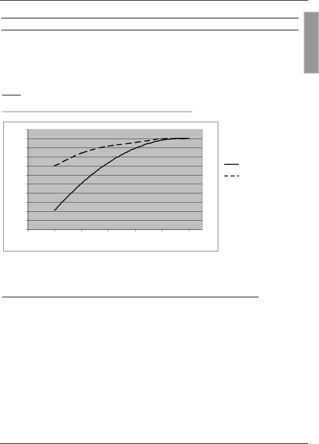
8.4. Der Einfluß von Metall auf die Reichweite
Metall und andere leitende Stoffe kann ein magnetisches Feld nicht durchdringen. Der Feldlinien-
verlauf und die Induktivität der Antenne wird verändert und hat somit einen großen Einfluß auf die
Reichweite. Weiterhin wird das Feld durch die Gegeninduktivität bzw. die Wirbelströme im Metall
geschwächt.
Die Änderung der Induktivität kann mit Hilfe der Abgleichelektronik meist ausgeglichen werden.
Bild 13 zeigt den Einfluß einer Metallplatte auf die Antenne mit (obere Linie) und ohne Nachgleich.
Bild 13: Lesereichweite* in Abhängigkeit zum Abstand zu Metall
Ohne Nachgleich
Mit Nachgleich
*Label 46 x 75 mm2, über der Antennen Mitte, Empfindlichkeit / Minimale Feldstärke Hmin=85mA/m
rms, parallele Ausrichtung des Labels zur Antenne. Sendeleistung 4 W
Ist Metall in der Nähe der Antenne nicht zu vermeiden sollte folgendes beachtet werden:
• Mindestabstand Metall zur Antenne 10 cm. Ab 30 cm ist mit starken Einbusen der Lesereich-
weite zu rechnen. Ab 50 cm Abstand zum Metall ist nahezu kein Einfluß meßbar.
• Die Metallteile dürfen keine geschlossenen Schleifen oder Stromkreise bilden. Diese sind gege-
benenfalls an einer Stelle elektrisch zu trennen.
• Die Metallteile in unmittelbarer Nähe der Antenne sind mit einer guten HF-Verbindung sternför-
mig zu Erden.
30
35
40
45
50
55
60
65
70
75
80
85
0 102030405060
Abstand zur Metallplatte [cm]
Reichweite [cm]
OBID® i-scan Montage ID ISC.ANT800/600
FEIG ELECTRONIC GmbH Seite 32 von 75 M01004-2de-ID-B.doc
D E U T S C H
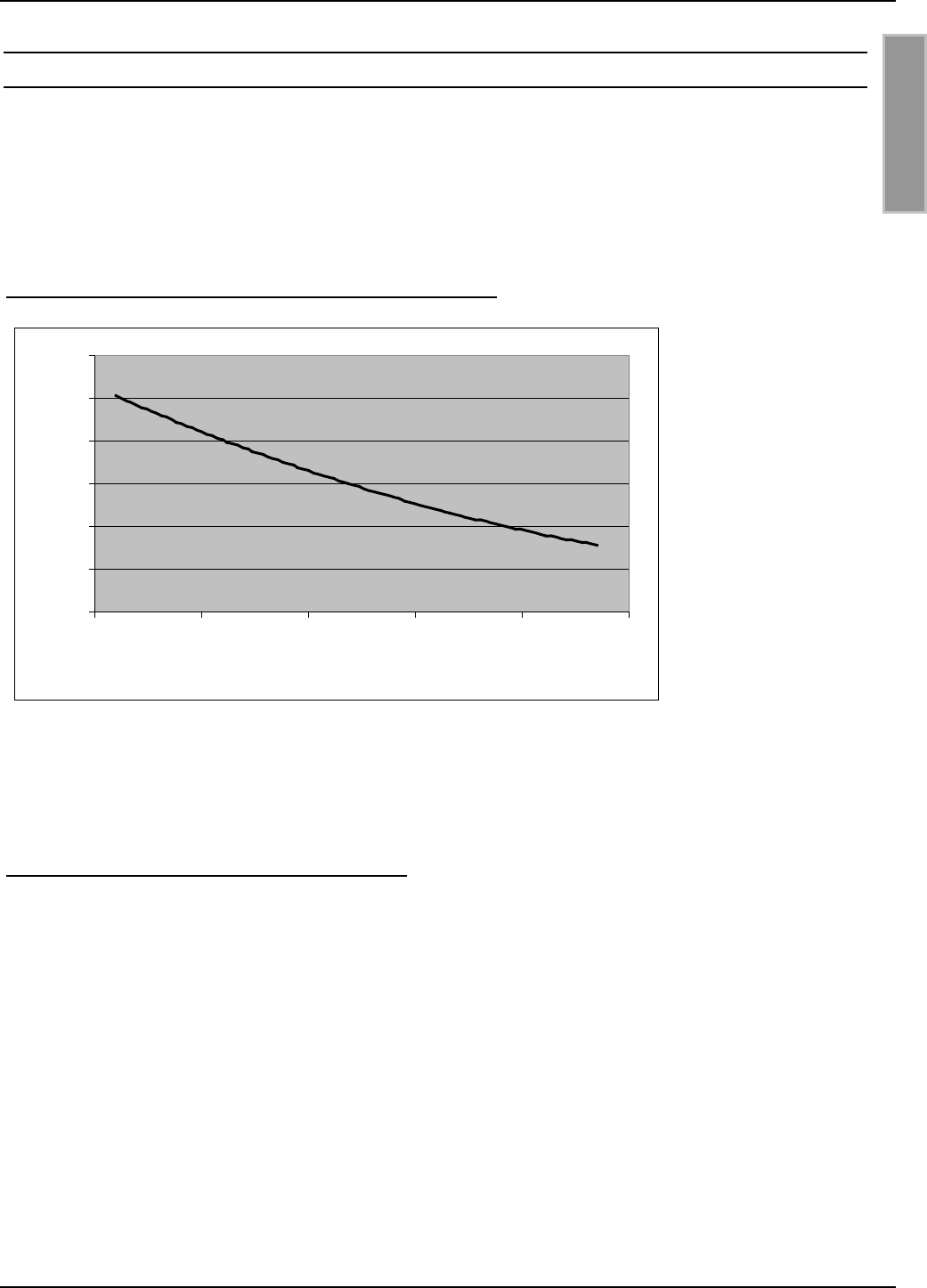
8.5. Der Einfluß der Noise Level auf die Reichweite der Antenne
Damit das Smart Label vom Empfänger auch bei kleinen Signalpegeln zuverlässig gelesen werden
kann, müssen Störungen weitgehend vermieden werden. Die Amplitude der Störpegel läßt sich am
Reader ID ISC.LR200 an Hand der Noise Level abfragen. Dabei sind nicht die absoluten Meß-
werte sondern die Differenz zwischen Umax und Umin ausschlaggebend.
Im Bild 14 wurde dies bei 4 W Sendeleistung simuliert und grafisch dargestellt.
Bild 14: Lesereichweite* in Abhängigkeit der Noise Level
*Label 46 x 75 mm2, über der Antennen Mitte, Empfindlichkeit / Minimale Feldstärke Hmin=85mA/m
rms, parallele Ausrichtung des Labels zur Antenne. Sendeleistung 4 W
Gute Werte von Umax-Umin für Basisantennen sind 20mV sowie für Gateantennen 40mV.
Ursache für zu hohe Noise Level können sein:
• Schlechte (HF-)Verbindungen zwischen Reader und Antenne.
• Falsche Kabelführung zwischen Antenne und Reader
• Eine schlecht abgestimmte Antenne
• Störsignale von anderen elektronischen Geräten oder Sendern.
• Störsignale auf der Energieversorgungsleitung des Readers
• Störsignale von anderen Kabel in der Nähe der Kabel zum und vom Reader
• Metall in der Nähe der Antenne
30
40
50
60
70
80
90
0 100 200 300 400 500
Umax-Umin [mV]
Reichweite [cm]
OBID® i-scan Montage ID ISC.ANT800/600
FEIG ELECTRONIC GmbH Seite 33 von 75 M01004-2de-ID-B.doc
D E U T S C H
8.6. Das Messen des Stehwellenverhältnisses VSWR
Wurde eine Antenne abgeglichen oder haben sich die Umgebungsbedingungen geändert, stellt
sich die Frage: Wie gut ist die Anpassung zwischen Reader und Antenne? Ein nützliches Hilfsmit-
tel zur Beurteilung der Anpassung der Antenne an die Impedanz von 50 Ω ist das VSWR Meter.
Dieses Gerät mißt das Verhältnis zwischen zugeführter und reflektierter Energie. Dabei gilt ein
VSWR bis zu 1.3 :1 als guter Wert. In VSWR-Meter sind sehr oft auch Watt-Meter integriert.
Bild 15: Einbau eines VSWR-Meters in das Antennenkabel
Das Kabel zwischen Reader und SWR Meter sollte entweder sehr kurz (< 20 cm) oder 7,20 m (RG
58=Lamba/2) lang sein. Liegt das VSWR nach dem Abgleichen über 1,3 : 1, kann mit Hilfe der
Trimmkondensatoren C1 und C2 geringfügig nachgeglichen werden.
Weiterhin kann mit dem Gerät jederzeit die Abstimmung der Basisantennen kontrolliert werden.
Kommt es zu einer Verstimmung der Antenne durch Änderungen der Umgebungsbedingungen,
läßt sich dies jederzeit feststellen.
Zusätzlich zu den vom SWR angezeigten Verlusten durch die Fehlanpassung zwischen Kabel und
Antenne kommt, daß der Reader in Abhängigkeit von der Antennenimpedanz verschiedene
Ausgangsströme treibt und somit verschiedene Leistungen ausgibt. D.h bei 50 Ω fließt ein Strom
von ca. 0.3 A. Bei einem offenen Ausgang fließt kein Strom, im Kurzschlußfall wird der Strom auf
ca. 1,0 A begrenzt. Auch hat die Anpassung der Antenne einen geringen Einfluß auf die Noise
Pegel.
Basisantenne
ID ISC.
A
NT800/600
VSWR / Power Meter
Reader
ID ISC.LR200
OBID® i-scan Montage ID ISC.ANT800/600
FEIG ELECTRONIC GmbH Seite 34 von 75 M01004-2de-ID-B.doc
D E U T S C H
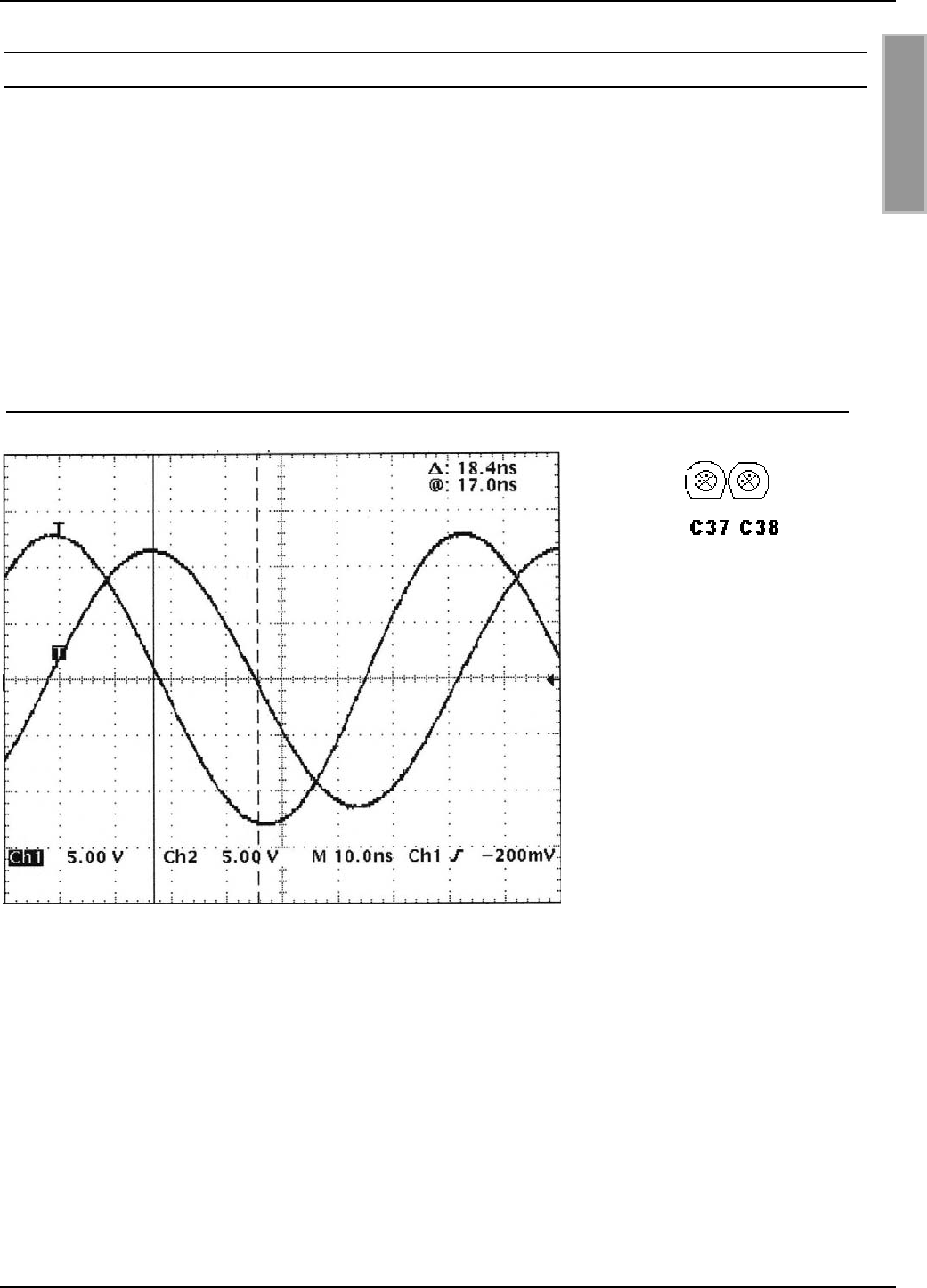
8.7. Messen des Phasenwinkel und Überprüfung der Ströme in der Antenne
Zur Kontrolle oder zur Feinjustierung des Phasenwinkels zwischen Basis- und
Ergänzungsantenne kann mit Hilfe eines Oszilloskops und zwei kleinen Meßschleifen aus Draht
(Siehe 10. Anhang A Hilfreiche Werkzeuge für den Aufbau und Test der Antennen) der
Phasenwinkel gemessen werden. Bei 13,56 MHz und einer Phasenverschiebung von 90°
zwischen Basis- und Ergänzungsantenne ergibt sich eine Zeitverzögerung von 18,4 ns. Bild 16
zeigt eine Hardcopy dieser Messung.
Mit den Trimmkondensatoren C37 und C38 kann die Phase der Ströme zwischen den beiden
Antennen korrigiert werden. Nach dem Abgleichvorgang sollten die beiden zusammengehörigen
Trimmkondensatoren C37, C38 immer ungefähr auf die gleiche Kapazität eingestellt sein.
Bild 16: Phasendifferenz zwischen Basis- und Ergänzungsantenne Bild 17: gleiche C-Werte
Reicht der Einstellungsbereich
der Trimmkondensatoren nicht
aus, sollte der beste mögliche
Phasenwert eingestellt werden.
Jetzt müssen beide
Trimmkondensatoren auf
Minimum oder Maximum stehen.
Anschließend sollten die
Kondensatoren um 180°
verdreht werden z.B. von Einstellung Minimum auf Maximum. Nun ist ein erneuter Abgleich der
Antennen mit Hilfe des Controller ID ISC.SAT.C notwendig. Danach steht der doppelte Einstellbe-
reich zu Verfügung.
Weiterhin sollte der Antennenstrom in beiden Antennen eines Gates gleich groß sein. Dies läßt
sich mit Hilfe der Messung der Amplitude kontrollieren und durch Veränderung des
Reihenwiderstandes R (JP8, JP1-4) korrigieren.
Sind beide Ströme gleich groß so teilt sich die Sendeleistung des Readers gleichmäßig auf beide
Antennen auf. D.h. in einen Gate aus zwei Antennen und einer eingestellten Sendeleistung von
8 W arbeiten beide Antennen mit 4 W.
Wichtig: Beide Meßschleifen müssen gleich groß sein, die gleiche Kabellänge haben, an der
gleichen Position an der Antenne montiert sein und genau parallel zueinander stehen. Ferner
sollten sie möglichst in der Mitte der Antennenfläche angebracht werden.

OBID® i-scan Montage ID ISC.ANT800/600
FEIG ELECTRONIC GmbH Seite 35 von 75 M01004-2de-ID-B.doc
D E U T S C H
9. Technische Daten ID ISC.ANT800/600-A und ID ISC.ANT800/600-B
Mechanische Daten
• Gehäuse Kunststoff ABS
• Abmessungen ( B x H x T ) 852 x 620 x 40 mm ± 1 mm
• Gewicht
– ID ISC.ANT800/600-A
– ID ISC.ANT800/600-B
ca. 2,7 kg
ca. 2,5 kg
• Schutzart IP 65
• Farbe Schwarz
Elektrische Daten
• Maximale Sendeleistung 8 W
• Zulässige Sendeleistung
– EU-Raum (lt. EN 300 330)
– USA (lt. FCC Part 15)
4,0 W
1,5 W
• Betriebsfrequenz 13,56 MHz
• Reichweite Maximal 80 cm*
• Antennenanschluß 1 x SMA Stecker (50 Ω)
• Antennenanschlußkabel RG58, 50 Ω, ca. 3,6 m lang
Umgebungsbedingungen
• Temperaturbereich
– Betrieb
– Lagerung
–25°C bis +55°C
–25°C bis +60°C
• Vibration EN60068-2-6
10 Hz bis 150 Hz : 0,075 mm / 1 g
• Schock EN60068-2-27
Beschleunigung : 30 g

OBID® i-scan Montage ID ISC.ANT800/600
FEIG ELECTRONIC GmbH Seite 36 von 75 M01004-2de-ID-B.doc
D E U T S C H
Angewendete Normen
• EMV EN 300 683
• Sicherheit
– Europa
– USA
EN 60950 (Auf Anfrage)
UL 1950 (Auf Anfrage)
*Label 46 x 75 mm2, über der Antennen Mitte, Empfindlichkeit / Minimale Feldstärke Hmin=85mA/m
rms, parallele Ausrichtung des Labels zur Antenne. Sendeleistung 4 W.
OBID® i-scan Montage ID ISC.ANT800/600
FEIG ELECTRONIC GmbH Seite 37 von 75 M01004-2de-ID-B.doc
D E U T S C H
10. Anhang A Hilfreiche Werkzeuge für den Aufbau und Test der Antennen
Für die Fehlersuche oder Inbetriebnahme der Antennen werden folgende Geräte empfohlen :
• Laptop oder Personal Computer (PC) mit dem Betriebssystem Microsoft Windows 95, 98, ME,
2000, XP.
• Servicesoftware ISCStart. Die Software ISCStart finden Sie auf der OBID® i-scan CD der Fir-
ma FEIG ELECTRONIC GmbH.
• SWR und Power Meter inklusive der Adapter auf SMA.
• 1 Stück Abschlußwiderstand 50 Ω mit Anschluß SMA–Male Buchse oder Abschlußwiderstand
50 Ω mit Adapter SMA–Male auf BNC.
• 1 Stück Kabel RG 58 C/U ca. 20 – 25 cm lang mit zwei SMA Steckern (In der Regel Selbst-
bau).
• Abgleich- bzw. Bernsteinschraubendreher mit Kunststoffklinge 2,4x0,5mm
• Oszilloskop 2 Kanäle, Zeitbasis mindestens 10ns/Div bzw. analog Bandbreite von 100 MHz
• 2 Stück Meßschleifen mit einem1,5 m langen Anschlußkabel (Bestehend aus 50 Ohm RG58
Kabel mit BNC Stecker und Drahtschleife (Durchmesser ca. 75 mm) am anderen Ende, (In der
Regel Selbstbau)
Optional sind folgende Werkzeuge hilfreich:
• HF Impedanz Analyser (Für 13,56 MHz)
Schirm
Innenleiter
BNC-Stecker
RG58 Kabel 2,5 m
ø 75

OBID® i-scan Montage ID ISC.ANT800/600
FEIG ELECTRONIC GmbH Seite 38 von 75 M01004-2de-ID-B.doc
D E U T S C H
10.1. Gerätevorschläge und mögliche Bezugsquellen :
1. VSWR – Meter
Alan CTE International VSWR & Power – Meter KW 220
Lieferanten:
• CB Funkshop Rößner, 91637 Wörnitz, Tel.09868/932945, http://www.cb-funkshop.de
• Garant – Funk, 53879 Euskirchen, Tel. 02251/55757
Alan CTE Internaltional VSWR und Wattmeter K155
Lieferant :
• Conrad Electronic
2. Antennen Analyzer
MFJ HF/UHF SWR Analyzer
Model MFJ-259B, 1.8 – 170 MHz
Lieferanten:
• Austin Amateur Radio Supply, USA 1-800 423 2604
• VHT – Impex, Ecke, Deutschland, Tel.: 05224/9709-0
CIA – HF Complex Impedance Analyzer 5012 – 5000
Lieferanten:
• AEA, Vista, California 92083, USA
• Garant – Funk, 53879 Euskirchen, Tel. 02251/55757
3. Adapter : UHF-> BNC, BNC-SMA, SMA-SMA, Abschlußwiderstand 50 Ω
Lieferanten:
• Bürklin OHG, http://www.buerklin.com
• Conrad.com AG, http://www.conrad.de
• Farnell Electronic Components GmbH, 82041 Oberhaching, http://www.farnell.com
4. Bernstein- / Abgleichschraubendreher mit Kunststoffklinge
Klingengröße: 2,4x0,5mm
Lieferant:
Bürklin Bestellnummer 06 L 8364

OBID® i-scan Montage ID ISC.ANT800/600
FEIG ELECTRONIC GmbH Seite 39 von 75 M01004-2de-ID-B.doc
D E U T S C H
5. Oszilloskope
Tektronix TDS 210 oder ein Gerät der TDS2xx bzw 3xx. Serie
Agilent 54622D oder ein Gerät der 546xx Serie
Voltcraft 100 MHz- Oszilloskop 6100
Hameg HM 407 oder HM 1507-3
Lieferanten:
• Tektronix Inc, http://www.tektronix.de oder http://www.tektronix.com
• Agilent Technoligies, http://www.agilent.com
• Conrad Electronic GmbH, 92240 Hirschau, http://www.conrad.de
• ELV Elektronik AG 26787 Leer, http://www.elv.de oder http://www.elv.com
• DataTec GmbH, 72770 Reutlingen, http://www.datatec.com
6. EMV- Ferrit Ringkerne
Durchmesser da=28, di=16, I=20, B.Nr.742 701 4
Durchmesser da=40,6 di=27,4 I=15, B.Nr.742 701 5
Lieferant
Würth Elektronik GmbH & Co.KG
Riedenstraße 16
74635 Kupferzell
Tel.: 07944 / 91 93 0
www.wuerth.de oder www.wuerth.com

OBID® i-scan Montage ID ISC.ANT800/600
FEIG ELECTRONIC GmbH Seite 40 von 75 M01004-2de-ID-B.doc
D E U T S C H
Included:
• 1 antenna ID ISC.ANT800/600-A or ID ISCANT800/600-B including connector cable
• This document
The user is cautioned that changes or modifications not expressly approved by the
FEIG ELECTRONIC GmbH could void they our authority to operate this equipment.
Note
Copyright 2002 by
FEIG ELECTRONIC GmbH
Lange Strasse 4
D-35781 Weilburg-Waldhausen
Tel.: +49 6471 3109-0
http://www.feig.de
Edition: wm/02/06/03 - m01004-2de-id-bwm2805.doc
With the edition of this document, all previous editions become void. Indications made in this document may
be changed without previous notice.
Copying of this document, and giving it to others and the use or communication of the contents thereof are
forbidden without express authority. Offenders are liable to the payment of damages. All rights are reserved
in the event of the grant of a patent or the registration of a utility model or design.
Composition of the information in this document has been done to the best of our knowledge. FEIG
ELECTRONIC GmbH does not guarantee the correctness and completeness of the details given in this
document and may not be held liable for damages ensuing from incorrect or incomplete information. Since,
despite all our efforts, errors may not be completely avoided, we are always grateful for your useful tips.
The installation instructions given in this document are based on advantageous boundary conditions. FEIG
ELECTRONIC GmbH does not give any guarantee promise for perfect function in cross environments.
FEIG ELECTRONIC GmbH assumes no responsibility for the use of any information contained in this
document and makes no representation that they free of patent infringement. FEIG ELECTRONIC GmbH
does not convey any license under its patent rights nor the rights of others.
OBID® is registered trademark of FEIG ELECTRONIC GmbH.

OBID®Installation ID ISC.ANT800/600
FEIG ELECTRONIC GmbH Page 41 of 75 M01004-2de-ID-B.doc
E N G L I S H
Contents
1. Safety Instructions / Warning - Read before start-up ! 43
2. Operating principles of the OBID® i-scan System 44
3. Performance features of the ID ISC.ANT800/600-A Antenna Type A 44
4. Performance features of the ID ISCANT800/600-B Antenna Type B 45
5. Possible configurations using the ID ISC.ANT800/600-x Antenna 46
5.1 Wiring options .....................................................................................................................46
5.2 Typical antenna assemblies...............................................................................................47
5.3 Required components for commissioning ......................................................................48
6. Assembly and wiring 49
6.1 Notes on routing antenna cable.........................................................................................52
7. Antenna tuning 53
7.1 Preparations .......................................................................................................................54
7.2 Tuning the base antenna....................................................................................................56
7.3 Tuning the second base antenna ......................................................................................59
7.4 Fine tuning the two antennas.............................................................................................60
7.5 Tuning the complementary antenna..................................................................................62
8. Startup 63
8.1 Radio regulatory agencies in EU countries and the USA................................................63
8.2 Special antenna configurations .........................................................................................64
8.3 The effect of transmitting power on reading range .........................................................66
8.4 The effect of metal on reading range ................................................................................67
8.5 The effect of noise level on antenna reading range.........................................................68

OBID®Installation ID ISC.ANT800/600
FEIG ELECTRONIC GmbH Page 42 of 75 M01004-2de-ID-B.doc
E N G L I S H
8.6 Measuring the standing wave ratio VSWR........................................................................69
8.7 Measuring the phase angle and checking antenna currents ..........................................70
9. Technical Data for ID ISC.ANT800/600-A and ID ISC.ANT800/600-B 71
10. Appendix: Helpful tools for constructing and testing the antennas 73
10.1 Recommended equipment and possible sources: ........................................................74

OBID®Installation ID ISC.ANT800/600
FEIG ELECTRONIC GmbH Page 43 of 75 M01004-2de-ID-B.doc
E N G L I S H
1. Safety Instructions / Warning - Read before start-up !
• The device has to be used only for the purpose designed by the manufacturer.
• The operation document has to be stored available at any time and has to be handed over to
each user.
• Unauthorized changes and the use of spare parts and additional devices which have not been
sold or recommended by the manufacturer may cause fire, electric shocks or injuries. Such
measures will lead to exclusion of any liability by the manufacturer.
• The liability-prescriptions of the manufacturer in the issue valid at the time of purchase are valid
for the device. The manufacturer is not legally responsible for incorrect, unsuitable document or
automatical setting of parameters for a device or the incorrect application of a device.
• Repairs can only be executed by the manufacturer.
• Installation-, operation- and maintenance procedures should only be carried out by qualified
personnel.
• Before opening the device, the power supply must always be interrupted. Make sure that the
device is without voltage by measuring. CAUTION! The fading of an operation control (LED) is
no indicator for an interrupted power supply or the device being without voltage!
• Works at the device and its installation have to be executed according to the national legal
requirements and local prescriptions.
• When working on devices the valid safety regulations must be observed.
• When working on an opened device note that the components may carry voltages of up to
1000V.
• The attached heat dissipater may become quite hot during operation.

OBID®Installation ID ISC.ANT800/600
FEIG ELECTRONIC GmbH Page 44 of 75 M01004-2de-ID-B.doc
E N G L I S H
2. Operating principles of the OBID® i-scan System
The OBID® i-scan system is an inductive transmission system for non-contact identification (ID) of
moving objects. The components of the read/write system permit programming and reading of
passive data carriers (transponders) – so-called “smart labels” – at a working frequency of 13.56
MHz. The system consists of a Reader, one of more antennas, and one or more labels as a dy-
namic storage medium for the data.
These smart labels are generally paper badges or tags with a wafer-thin transponder integrated for
communicating with RFID read/write devices.
As soon as a smart label arrives in the active zone of the antenna, it is inductively supplied with
energy and can be read and programmed. The returning data are received by the same antenna of
the Reader which generates the magnetic field and sends data to the tag.
The magnetic field and the data which are sent to and received from the tag can pass through vir-
tually any non-conducting material, so that reading and writing is also possible without line of sight.
The anti-collision function of the reader allows up to 50 smart labels per second to be read at one
time.
3. Performance features of the ID ISC.ANT800/600-A Antenna Type A
The base antenna ID ISC.ANT800/600-A Antenna Type A is a single loop antenna with tuning
electronics, and has been optimized as a sending and receiving antenna for the ID ISC.LR200
Reader. At a adjust transmitting power of 4 W a reading range of up to 80 cm is possible. The an-
tenna is also compatible with other Readers having a transmitting frequency of 13.56 MHz and an
output impedance of 50 Ω.
The antenna consists of an electrical antenna wire, housing and the tuning electronics
ID ISC.SAT.A Static Antenna Tuner Type A. The Tuner has been tuned and retains its setting for
the antenna as long as the ambient conditions remain unchanged.
The use of the Static Antenna Tuning Controller ID ISC.SAT.C-A is intended for initial installation of
an OBID i-scan long range application or if adjustments need to be made to the antenna tuning
due to changed ambient conditions.
The antenna has been factory tuned on a wood block for an impedance of 50 Ω. After installation
in different ambient conditions the ID ISC.SAT.C-A Static Antenna Tuning Controller may be used
to retune the antenna.
The antenna may be used for detecting objects or persons. It is suitable for both indoor and out-
door use.
The preferred orientation of a smart label is parallel to the antenna surface. The maximum range is
achieved over the center of the antenna surface.

OBID®Installation ID ISC.ANT800/600
FEIG ELECTRONIC GmbH Page 45 of 75 M01004-2de-ID-B.doc
E N G L I S H
4. Performance features of the ID ISCANT800/600-B Antenna Type B
The ID ISC.ANT800/600-B Antenna Type B is the complementary antenna for the base antenna
ID ISC.ANT800/600-A Antenna Type A. The base and complementary antennas comprise a gate
for detecting persons or objects. Depending on the antenna configuration from 1 to a maximum of
3 read directions for the smart labels and antenna separations (gate widths) of from 0.80 to 1.50 m
are possible (ISO card size smart label).
The antenna consists of the electrical antenna wire, housing and the ID ISC.SAT.B Static Antenna
Tuner Type B. The Tuner is tuned using the Static Antenna Tuning Controller ID ISC.SAT.C-A and
retains its setting for the antenna as long as the ambient conditions remain unchanged.
The antenna receives its power via magnetic coupling from the base antenna. To optimize the read
distance the received signal (label reply) is electrically decoupled on the complementary antenna.
The connection to the 2 receivers of the ID ISC.LR200 Reader is made using the coaxial cable
supplied.
Use of the Static Antenna Tuning Controller ID ISC.SAT.C-A is intended for initial installation of an
OBID i-scan Long Range Application or is required for adjusting the antenna tuning to changed
ambient conditions. The tuning procedure is described in the Mounting Instructions for the
ID ISC.SAT.C-A, ID ISC.SATA-A and ID ISC.SAT.B-A.
The preferred orientation of a smart label in the gate is parallel to the antenna surface and trans-
verse to the antennas at the front and back of the gate for vertical label orientation. Maximum
range is achieved in the center of the antenna surface in the gate.
OBID®Installation ID ISC.ANT800/600
FEIG ELECTRONIC GmbH Page 46 of 75 M01004-2de-ID-B.doc
E N G L I S H
5. Possible configurations using the ID ISC.ANT800/600-x Antenna
Various antenna assemblies can be connected to the ID ISC.LR200 Reader depending on the ap-
plication. Several wiring examples are shown below.
5.1 Wiring options
Figure 18: Circuit diagram: One Reader and one base antenna
Figure 19: Circuit diagram: One Reader and two base antennas
Figure 20: Circuit diagram: One Reader and one base and complementary antenna each
ID ISC.ANT.PS
ID ISC.ANT800/600-A
ID ISC.ANT800/600-A
Reade
r
ID ISC.ANT.T
ID ISC.ANT800/600-B
ID ISC.ANT800/600-A
Reade
r
Reade
r
ID ISC.ANT.T
ID ISC.ANT800/600-A
OBID®Installation ID ISC.ANT800/600
FEIG ELECTRONIC GmbH Page 47 of 75 M01004-2de-ID-B.doc
E N G L I S H
Figure 21, Circuit diagram: One Reader and two base and complementary antennas each
5.2 Typical antenna assemblies
No. Type Required units Application
1 One Reader and one
base antenna
1 x ID ISC.LR200-A
1 x ID ISC.ANT.T-A
1 x ID ISC.ANT800/600-A
Simple applications with 1 read di-
rection respectively. label orienta-
tion, up to 50 cm range
2 One Reader and two
base antennas
1 x ID ISC.LR200-A
1 x ID ISC.ANT.PS-A
2 x ID ISC.ANT800/600-A
Gate applications with large gate
openings and one or 2 read direc-
tions respectively label orientations
3 One Reader and two
base antennas in fixed
position
1 x ID ISC.LR200-A
1 x ID ISC.ANT.PS-A
2 x ID ISC.ANT800/600-A
Simple applications with 1 read di-
rection respectively label orienta-
tion, up to 80 cm range. RF ap-
proval possible without shielding.
4 One Reader and one
base plus one com-
plementary antenna
1 x ID ISC.LR200-B
1 x ID ISC.ANT.T-A
1 x ID ISC.ANT800/600-A
1 x ID ISC.ANT800/600-B
Gate applications up to 1 m and 2
or 3 read directions respectively
label orientations. May be possible
with RF approval with shielding.
5 One Reader and two
base plus two com-
plementary antennas
1 x ID ISC.LR200-B
2 x ID ISC.ANT.PS-A
2 x ID ISC.ANTx00/x00-A
2 x ID ISC.ANTx00/x00-B
Gate applications with 2 gates one
behind the other up to 1 m gate
opening, large read windows and 3
read directions respectively label
orientations. RF approval possible.
2 x ID ISC.ANT.PS
2 x ID ISC.ANT800/600-B
2 x ID ISC.ANT800/600-A
Reade
r

OBID®Installation ID ISC.ANT800/600
FEIG ELECTRONIC GmbH Page 48 of 75 M01004-2de-ID-B.doc
E N G L I S H
5.3 Required components for commissioning
• Qty. 1 ID ISC.SATC-A Automatic Tuning Controller
• Service software ISCStart Version 4.02 or higher on a PC running under MS Windows. The
ISCStart software is contained on the OBID® i-scan CD-ROM available from FEIG
ELECTRONIC GmbH.
• Qty. 1 SWR Meter with SMA sockets or adapter to SMA sockets
• Qty. 1 cable RG 58 C/U approx. 20 – 25 cm long with 2 SMA plugs
• Qty. 1 amber blade screwdriver (Tuning tool for tuning capacitors).
• Qty. 1 Oscilloscope (Tuning antenna ID ISC.ANT800/600 Type B)
• Qty. 2 test loops (Tuning antenna ID ISC.ANT800/600 Type B)
For additional information on these devices, see the individual instructions or section 10. Appendix:
Helpful tools for constructing and testing the antennas.
OBID®Installation ID ISC.ANT800/600
FEIG ELECTRONIC GmbH Page 49 of 75 M01004-2de-ID-B.doc
E N G L I S H
6. Assembly and wiring
The antennas ID ISC.ANT800/600 Type A and B are designed for attachment to fixtures made of
non-conducting materials (e.g. plastic or wood) and for both indoor and outdoor use. Six mounting
holes are provided for attaching the antenna in the inside of the antenna (d=5.4 mm). Hole spac-
ing: see Figure 22. For attachment, we recommend a wood screw (like DIN 96) or machine screw
(like DIN 7985) with pen head and minimum ∅ 10 mm till maximum ∅ 12 mm. The maximum tight-
ening torque of the free turning screws are 2 Nm.
If the existing holes are not sufficient, additional holes (d=5.4 mm) may be drilled inside the
hatched lines.
The antenna must be kept a minimum of 10 cm from metal parts! Beyond 50 cm distance from
metal parts some read distance will be sacrificed.
Figure 22:Assembly diagram for ID ISC.ANT800/600 Types A and B
All measurements in mm.
For antenna tuning open the housing by removing the four screws at the cover. The maximum
tightening torque for the cover screws is 0,2 Nm – 0,25 Nm.
If several antennas must be installed adjacent to each other, ensure that the covers can be opened
from one side. Additionally the covers must be arranged left and right. See Figure 23.
antenna opening
(cover)
510
38
26
620±1
5,4
13
852±1
728
364
838±1
OBID®Installation ID ISC.ANT800/600
FEIG ELECTRONIC GmbH Page 50 of 75 M01004-2de-ID-B.doc
E N G L I S H
Figure 23: Assembly sketch, view from top
If a gate is constructed using one/two base and one/two complementary antennas, the antenna
opening/covers should all face the outside (away from the gate) or all towards the center of the
gate.
Connect the antennas directly to the Reader using the connector cable (see 5.1 Wiring options)
and an SMA connector. To suppress noise effects in industrial environments we recommend also
connecting the ID ISC.ANT.T Antenna Transformer for i-dist between the Reader and base an-
tenna.
To suppress any possible noise, 2 ring cores are supplied with the ID ISC.LR200 Reader. These
should be installed in the antenna connector cable for the base and complementary antenna. To
do this pull the antenna connector cable 4 times through the core so that the cable is located as
closely as possible to the core. The maximum distance between reader and toroidal cores should
be 10 cm.
Figure 24: Assembly of the toroidal core at the coaxial cable
In order to meet EMC requirements in the USA as prescribed by FCC Part 15, a second ring cores
must be installed in the cable for antenna models ID ISC.ANT800/600 Type A and B (see drawing).
The 28 mm x 20 mm EMC ring core included with the Reader is attached to the front end of the
cable. The antenna cable must be wound tightly around the ring core at least four times. The dis-
tance between the Reader connection and the ring core should be max. 10 cm.
The 41 mm x 15 mm ring core must be installed in the exact middle of the antenna cable. Wind the
coaxial cable tightly through the ring core at least ten turns. This ring core is supplied with the an-
tennas.
OBID®Installation ID ISC.ANT800/600
FEIG ELECTRONIC GmbH Page 51 of 75 M01004-2de-ID-B.doc
E N G L I S H
Bild 25: Assembly of the two toroidal cores at the coaxial cable
After assembly you can check for proper function of the base antenna ID ISC.ANT800/600-A using
the Reader and a smart label. At a transmitting power of 4W and a label size of 70 x 54 mm (ISO
card size) the read range in the center of the base antenna should be approx. 80 cm.
If a gate has been constructed using a base and complementary antenna, you can use the Reader
and a smart label to check for proper function of the base antenna ID ISC.ANT800/600-A and the
complementary antenna ID ISC.ANT800/600-B. With both antennas having a transmitting power of
4 W, the label 46 x 75 mm2 (ISO card size), the gate opening 1 m and a label orientation parallel to
the antenna facing out (outside the gate), a read range of 70-80 cm should be achieved.
Otherwise an SWR meter to adjust the base antenna to an impedance of 50 Ω and check the noise
level at the reader. Checking the function of the complementary antenna is described in 8.7 Meas-
uring the phase angle and checking antenna currents.
If more than one antenna of type ID ISC.ANT800/600 or gates are attached to different Readers,
you must maintain a minimum separation of 10 m between the antennas or gates. Otherwise you
must synchronize the Readers.
Note: Voltages as high as 1000V may be present on the antenna wire or on various compo-
nents of the tuning boards. Before starting your work first disconnect the antenna from the
Reader. When plugging the ID ISC.SATC-A Controller into the antenna make sure no com-
ponents inside the housing are touched.
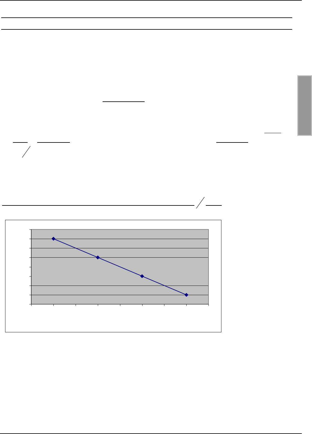
OBID®Installation ID ISC.ANT800/600
FEIG ELECTRONIC GmbH Page 52 of 75 M01004-2de-ID-B.doc
E N G L I S H
6.1 Notes on routing antenna cable
When routing cable and configuring individual antennas or antenna gates, note the following:
• Up to a distance of 50 cm the antenna cable should always be kept vertical to the antenna and
firmly tied down.
• If the antenna cable needs to be routed closer along the antenna, maintain a distance of at
least 20 cm.
• Always route and fix the cable before tuning. If changes are necessary later check the imped-
ance of the base antenna and check the phase and amplitude of the currents of the comple-
mentary antenna.
• In order to obtain optimum read distances the antenna connector cable should not be short-
ened or lengthened. If an extension is absolutely required, use only a 50 Ω cable with a length
of 2
λ
(half a wavelength at 13.56 MHz, RG58=7.20 m). A slight loss in sensitivity will likely re-
sult.
• The antenna cable must be kept a distance of at least 30 cm from any parallel routed power
cables.
Figure 26: Read distance as a function of antenna cable length in 2
λ
steps
*Label 46 x 75 mm2 over the centre of the antenna, sensitivity / minimum operating field
Hmin=85mA/m rms, parallel orientation to the antenna,. transmitting power 4 W
73
74
75
76
77
78
79
80
81
0 3,62 7,24 10,86 14,48 18,1 21,72 25,34 28,96
Antenna cable length [m]
Range [cm]
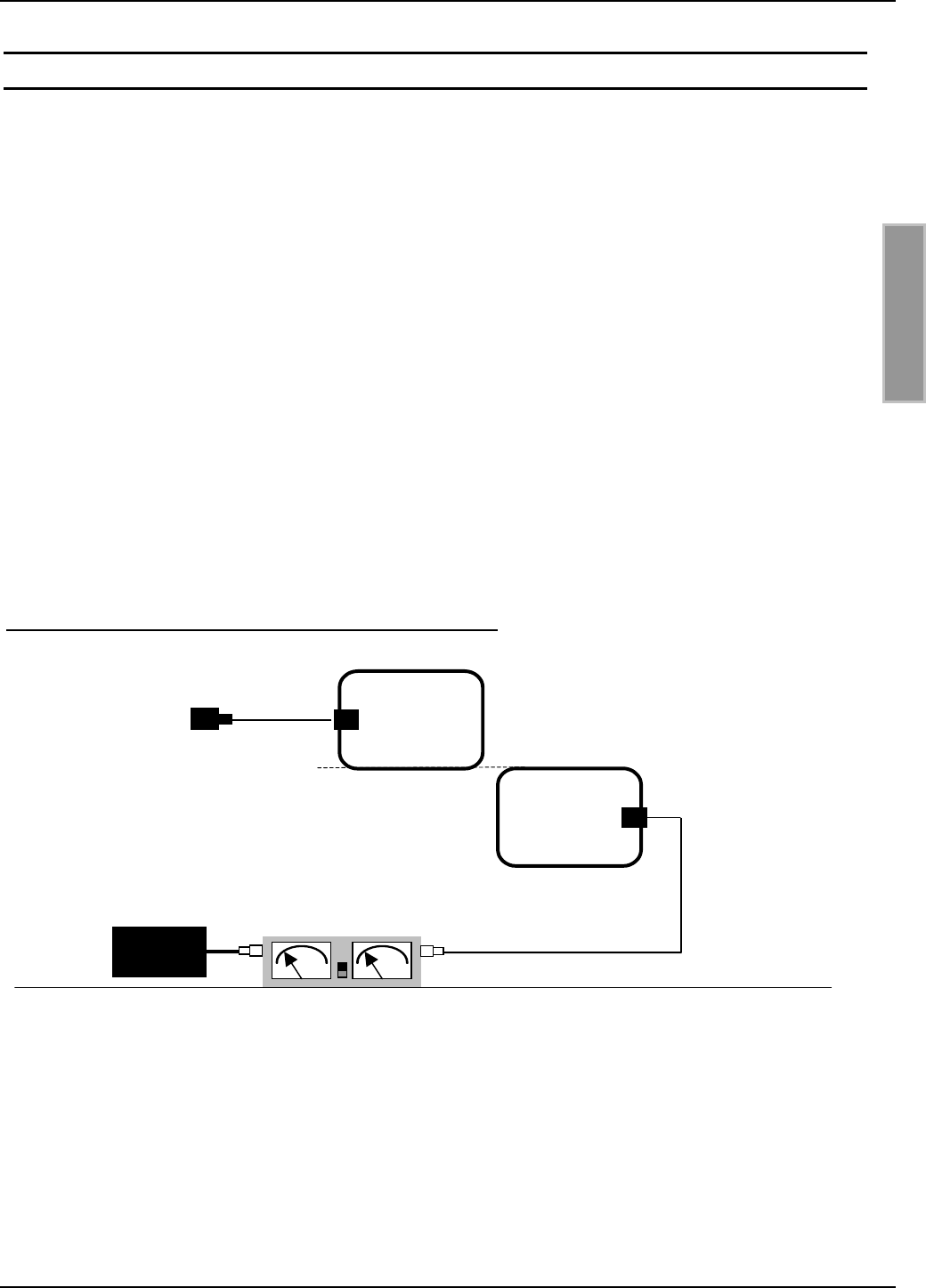
OBID®Installation ID ISC.ANT800/600
FEIG ELECTRONIC GmbH Page 53 of 75 M01004-2de-ID-B.doc
E N G L I S H
7. Antenna tuning
At least, two base antennas are necessary to follow the valid radio regulations with a output power
greater than 1 W. That´s the reason, why we use this standard configuration for this description.
If you like a gate with base antenna and complementary antenna see Application Note “Installation
and tuning of a gate antenna with 1 m x 1 m read window in any desired label orientation.
Document: N10900-2e-ID-B.DOC. This document can be found on the OBID® i-scan CD-ROM
supplied by FEIG ELECTRONIC GmbH.
Applications with four base antennas see Application Note: Installation and tuning of a gate an-
tenna made from four base antennas. Document: N11000-2e-ID-B.DOC. This document can be
found on the OBID® i-scan CD-ROM supplied by FEIG ELECTRONIC GmbH.
Before tuning the base or complementary antenna you must firmly mount the antennas and an-
tenna cable. The ID ISC.ANT.T-A Transformer and ID ISC.ANT.PS-A Power Splitter are attached
only after tuning the antennas.
To calibrate the antenna you must remove the cover over the antenna opening. The recommended
tightening torque of the cover screws when recovering the antenna 0.2 Nm – 0.25 Nm.
Next, connect the first base antenna directly to the Reader connector X2. Terminate the second
antenna using a 50 Ω termination resistor.
Figure 27: Configuration for tuning the first base antenna
Until the tuning procedure is completed, an SWR should be installed between the Reader and the
base antennas.
Begin the tuning procedure with the first base antenna. Next tune the second base antenna. Since
the two neighboring base antennas affect each other mutually, the first base antenna must then be
retuned.
2 x ID ISC.ANT800/600-A
ID ISC.LR200-A
50 Ω Dummy Load
Antenna 1
Antenna 2
SWR - Meter
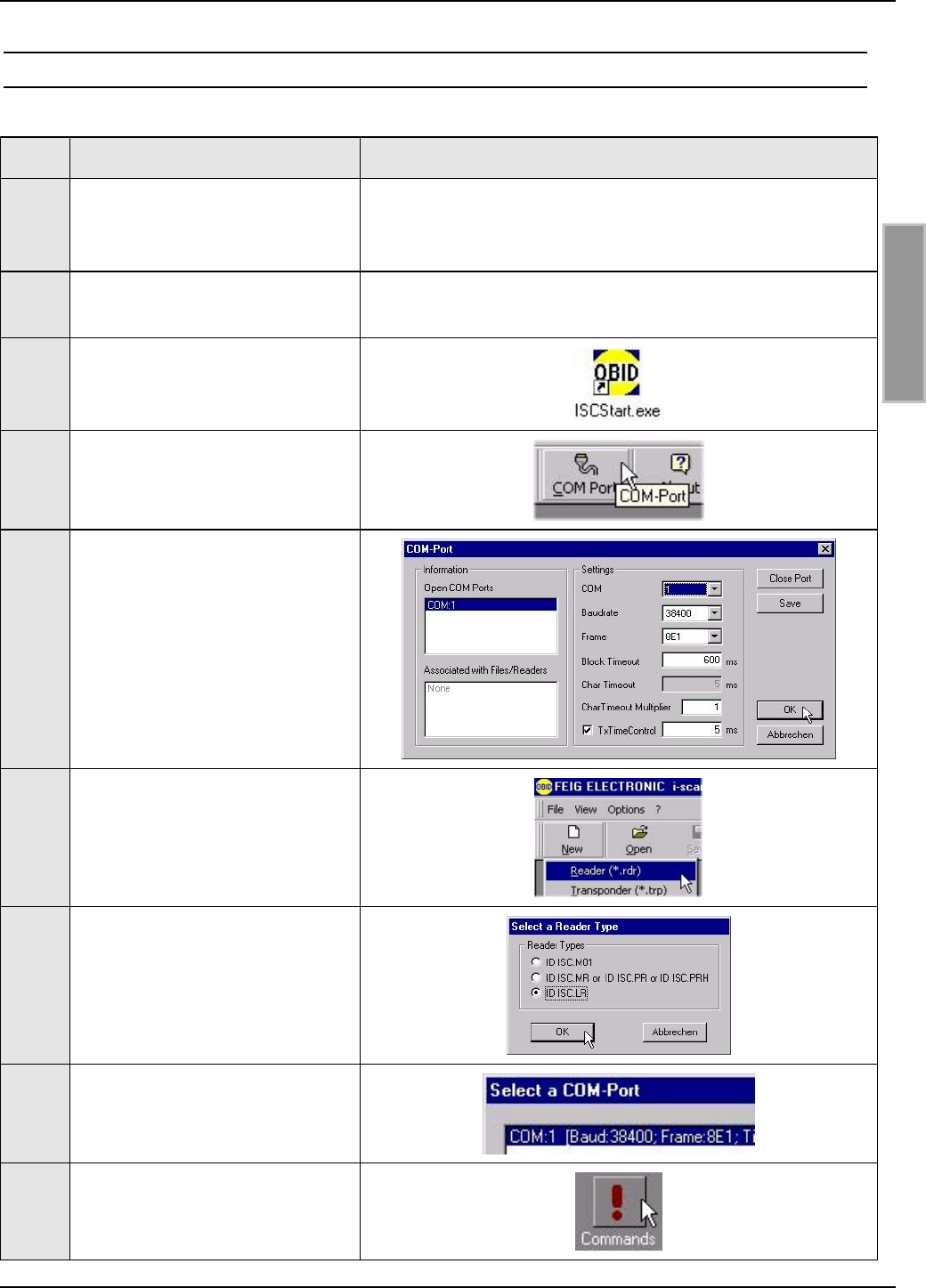
OBID®Installation ID ISC.ANT800/600
FEIG ELECTRONIC GmbH Page 54 of 75 M01004-2de-ID-B.doc
E N G L I S H
7.1 Preparations
Step Procedure Note
1Connect the ID ISC.LR200
Reader to the PC through the
RS232 or RS485 port
See Installation Manual ID ISC.LR200
2Install the Demo Software ISC-
Start
Located on the OBID® i-scan CD-ROM
3Run the ISCStart program
4Open the COM port settings
5Check the COM port settings
and confirm by clicking on OK.
6Now open the menu File – New
- Reader
7Select ID ISCLR and click on
OK
8Select COM: x [Baud
38400......]
9Click on Commands
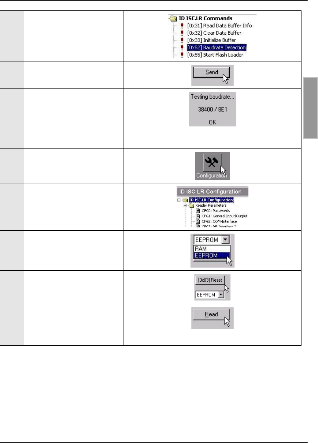
OBID®Installation ID ISC.ANT800/600
FEIG ELECTRONIC GmbH Page 55 of 75 M01004-2de-ID-B.doc
E N G L I S H
10 Select Baudrate Detec-
tion[0x52] command
11 Click on Send
12 The program tests all possible
baud rates. It stops as soon as
the baud rate set on the Reader
has been detected (default
38400 / 8E1) and confirms with
OK
13 Click on Configuration
14 Select ID ISCLR Configura-
tion.
15 Select destination memory
EEPROM instead of RAM.
16 Click on Reset [0x83] to set the
Reader to the default configu-
ration.
17 Click on Read to load the
Reader configuration into the
PC and to load the ISCStart
program.
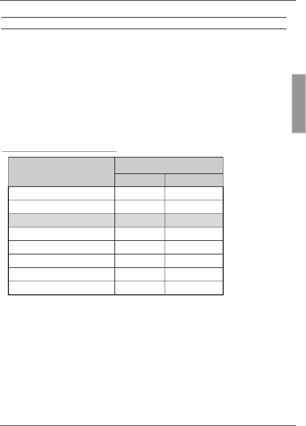
OBID®Installation ID ISC.ANT800/600
FEIG ELECTRONIC GmbH Page 56 of 75 M01004-2de-ID-B.doc
E N G L I S H
7.2 Tuning the base antenna
The base antenna has been factory tuned on a wood block to an impedance of 50 Ω. If it is
mounted in the vicinity of metal or together with another base or complementary antenna or other
magnetic conducting materials, the antenna must be tuned or retuned.
In this case, you should check the input impedance of the antenna. See section 8.6 Measuring the
standing wave ratio VSWR.
The determining factor for the magnetic field strength and thereby for the read range of the anten-
nas and adherence to the approval regulations for radio type systems is the antenna current. The
latter is affected by resistors R1-R4. The antenna was factory set to 3 Ω by inserting Jumper JP3.
Inserting or removing Jumpers JP1-JP4 and JP8 changes the resistance. The resistance values for
various jumper combinations are shown in the table below.
Table 2: Jumpers and resistance values
Jumper Total resistance R
JP8 in JP8 out
JP1 in 2.0 Ω0 Ω
JP2 in 2.4 Ω0.4 Ω
JP3 in** 3.0 Ω1.0 Ω
JP4 in 4.0 Ω2.0 Ω
JP2 and JP3 in 2.28 Ω 0.28 Ω
JP2 and JP4 in 2.33 Ω 0.33 Ω
JP3 and JP4 in 2.66 Ω 0.66 Ω
JP2, JP3 and JP4 in 2.23 Ω 0.23 Ω
** default configuration
If all jumpers are out the antenna circuit is interrupted.
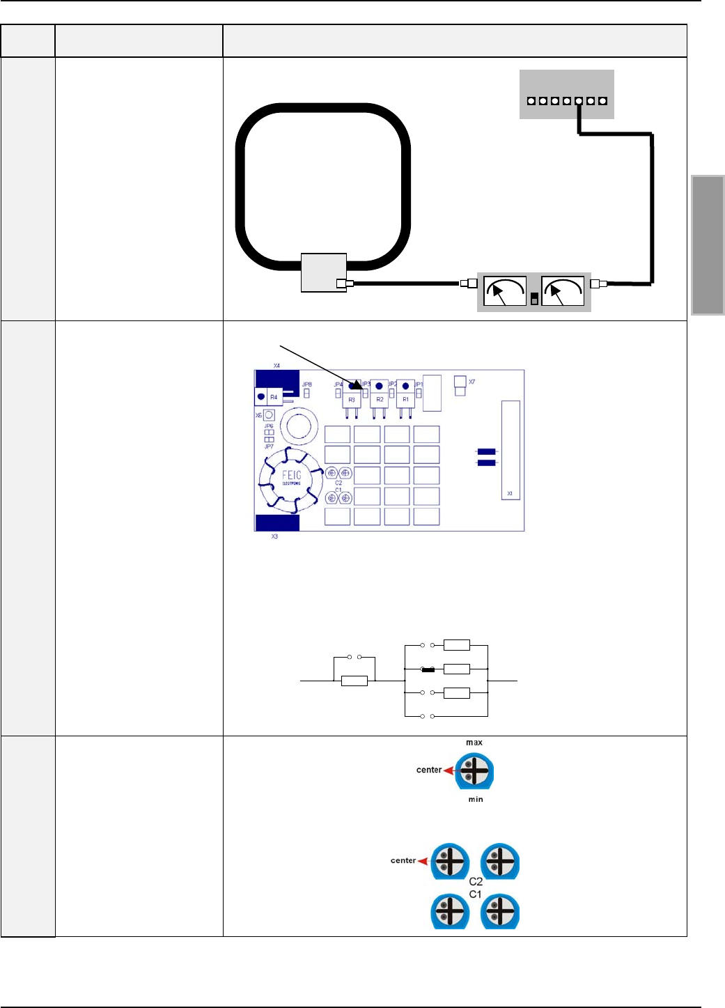
OBID®Installation ID ISC.ANT800/600
FEIG ELECTRONIC GmbH Page 57 of 75 M01004-2de-ID-B.doc
E N G L I S H
Step Procedure Note
1
Connect the Reader to
the base antenna
through the SWR
bridge.
See also section: 8.6
Measuring the stand-
ing wave ratio VSWR
2
Jumpers JP1 – JP4
and JP6 –8 should be
checked and set as
necessary.
Jumpers JP6 + JP7
are left out during
normal operation and
during tuning.
Jumper JP4 must be in.
JP1, JP2, JP4, JP6, JP7 and JP8 = out
Rges = 3 Ω
3
Set trim capacitors C1
and C2 to their center
position.
JP8
JP4
JP3
JP2
JP1
2
Ω
2
Ω
1
Ω
0,4
Ω
Base antenna
ID ISC
.ANT800/600-
A
SWR / Power Meter
Reader
ID ISC.LR200
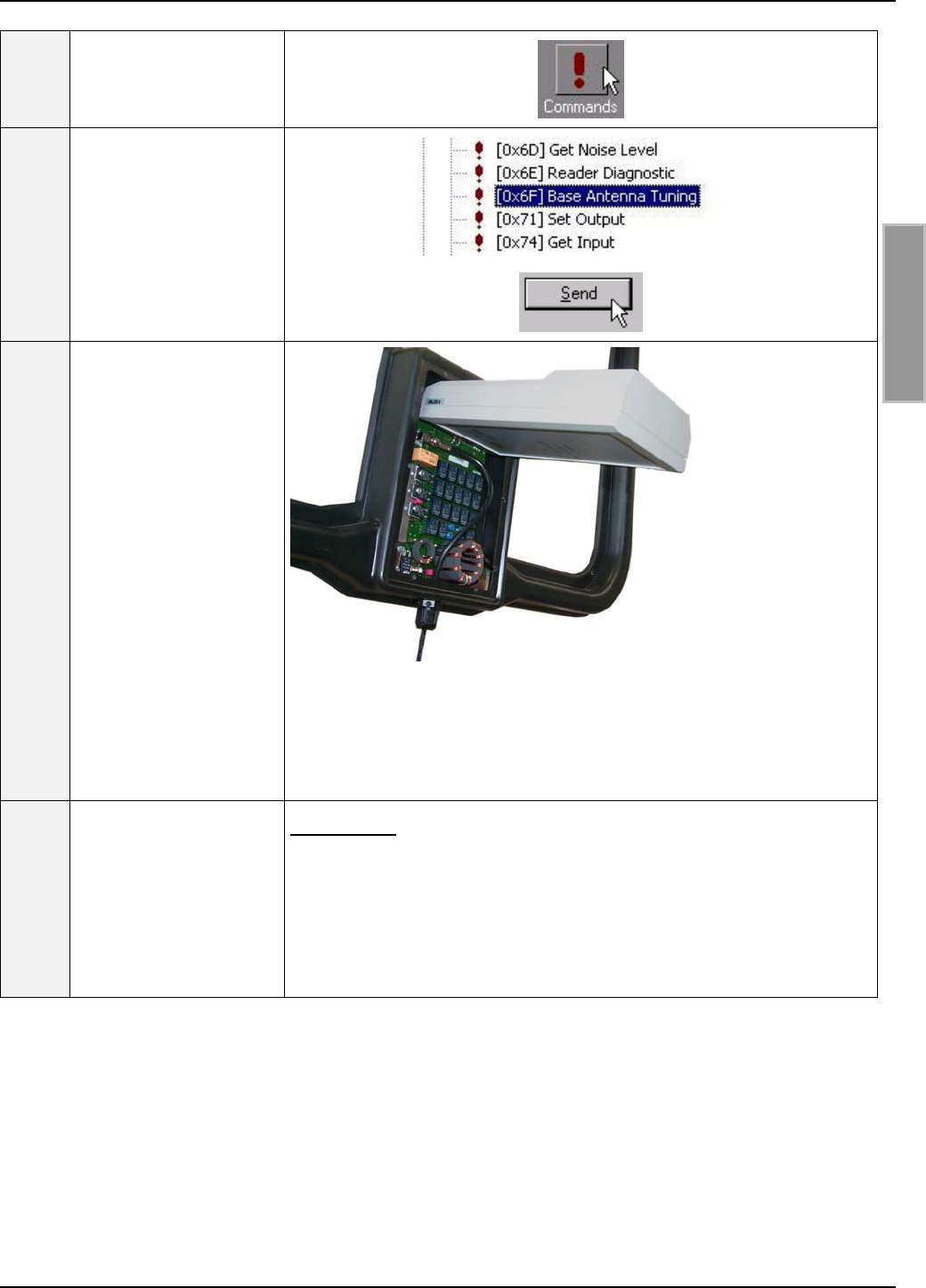
OBID®Installation ID ISC.ANT800/600
FEIG ELECTRONIC GmbH Page 58 of 75 M01004-2de-ID-B.doc
E N G L I S H
4Click on Commands
at the ISCStart Pro-
gram Window
5Select the command
[0x6F] Base Antenna
Tunning] and click on
Send to send all the
settings.
6
Now connect the Static
Antenna Tuning Con-
troller ID ISC.SAT.C-A
to the antenna tuner of
the base antenna and
press the “Start“ key
on the controller.
The tuning process
takes several seconds.
When completed, the
green LED will come
on for 4 seconds.
.
Tuning mode: Is activated by holding down the Start key greater
than two seconds (< 2 sec).
Control mode: Is activated by briefly pressing the Start key
shorter than two seconds (< 2 sec).
7
The controller runs
then automatically
turns off and can then
be unplugged.
Important:
Do not unplug the controller before
the green LED has gone out!
Now you may begin tuning the complementary antenna.

OBID®Installation ID ISC.ANT800/600
FEIG ELECTRONIC GmbH Page 59 of 75 M01004-2de-ID-B.doc
E N G L I S H
8
If the tuning was not
properly concluded,
this is indicated by the
red LED.
If an error occurs at
the beginning of the
tuning procedure, the
LED flashes for 4
seconds.
If an error occurs dur-
ing or at the end of the
tuning procedure, the
LED turns on solidly
for 4 seconds.
If the battery is low, the
yellow LED turns on
for 4 seconds.
If the red LED flashes for 4 seconds, this indicates there is no
RF power at the antenna.
Possible causes:
• Reader or RF power turned off.
• Cable between Reader and antenna defective.
• The SMA connectors were not properly attached to the Reader
or antennas or are not properly seated on the SMA sockets.
• The cable is pinched or shorted in the SMA plug.
♦ The controller was not properly plugged into the board.
If the red LED comes on solidly for 4 seconds, the tuning was not
properly finished.
Possible causes:
• Cable between Reader and antenna is defective.
• The SMA connectors were not properly attached to the Reader
or antennas or are not properly seated on the SMA sockets.
• The cable is pinched or shorted in the SMA plug.
♦ Modulation is turned on in the Reader.
♦ Antenna Q set too high (resistor settings).
♦ The controller was not properly plugged into the board.
♦ Tuner board is defective.
.
After tuning the base antennas you should check for proper function of the antenna using the
Reader and a smart label. At a transmitting power of 4W and a label size of 46 x 75 mm2 (ISO card
size) the read range in the center of the base antenna should be approx. 80 cm.
Otherwise you will need to adjust the base antenna to an impedance of 50 Ω as described in Sec-
tion 8.6 Measuring the standing wave ratio VSWR and then check the noise level on the Reader.
7.3 Tuning the second base antenna
To tune the second antenna, connect it to the Reader through the SWR meter. Terminate the end
of the antenna cable on the first antenna with a 50 Ω resistor. Use this configuration to tune as
described in section 7.2 Tuning the base antenna Step 1-8.
Since adjacent antennas will have a mutual coupling effect on each other depending on their
spacing, the first base antenna should once again be retuned.
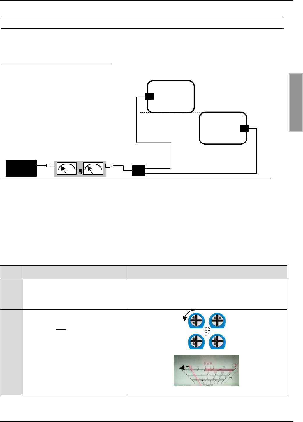
OBID®Installation ID ISC.ANT800/600
FEIG ELECTRONIC GmbH Page 60 of 75 M01004-2de-ID-B.doc
E N G L I S H
7.4 Fine tuning the two antennas
For fine tuning, the two antennas are connected with the Power Splitter and to the Reader through
the SWR meter.
Figure 28: Configuration for fine tuning
Since the tuning point of the antennas will deviate somewhat from the configuration during tuning
due to the mutual interference caused by magnetic coupling, the tuning point will need to be read-
justed slightly.
This can be accomplished with the help of an SWR meter and the four blue trim capacitors C1 and
C2 on the Tuner boards.
Step Procedure Note
1Connect the ID ISC.LR200 Reader
to both antennas thought the
Power Splitter and SWR-Meter.
Figure 28: Configuration for fine tuning
2Turn the leftmost of the two trim
capacitors C2 on Antenna 1 ap-
prox. ¼ - ½ turn counter-
clockwise.
The SWR must drop!
Always tune the SWR to the
smallest possible value.
2 x ID ISC.ANT800/600-A
ID ISC.LR200-A Power Splitter
Antenna 1
Antenna 2
SWR - Meter
3
,
6 m 3
,
6 m20 cm Cable len
g
ths
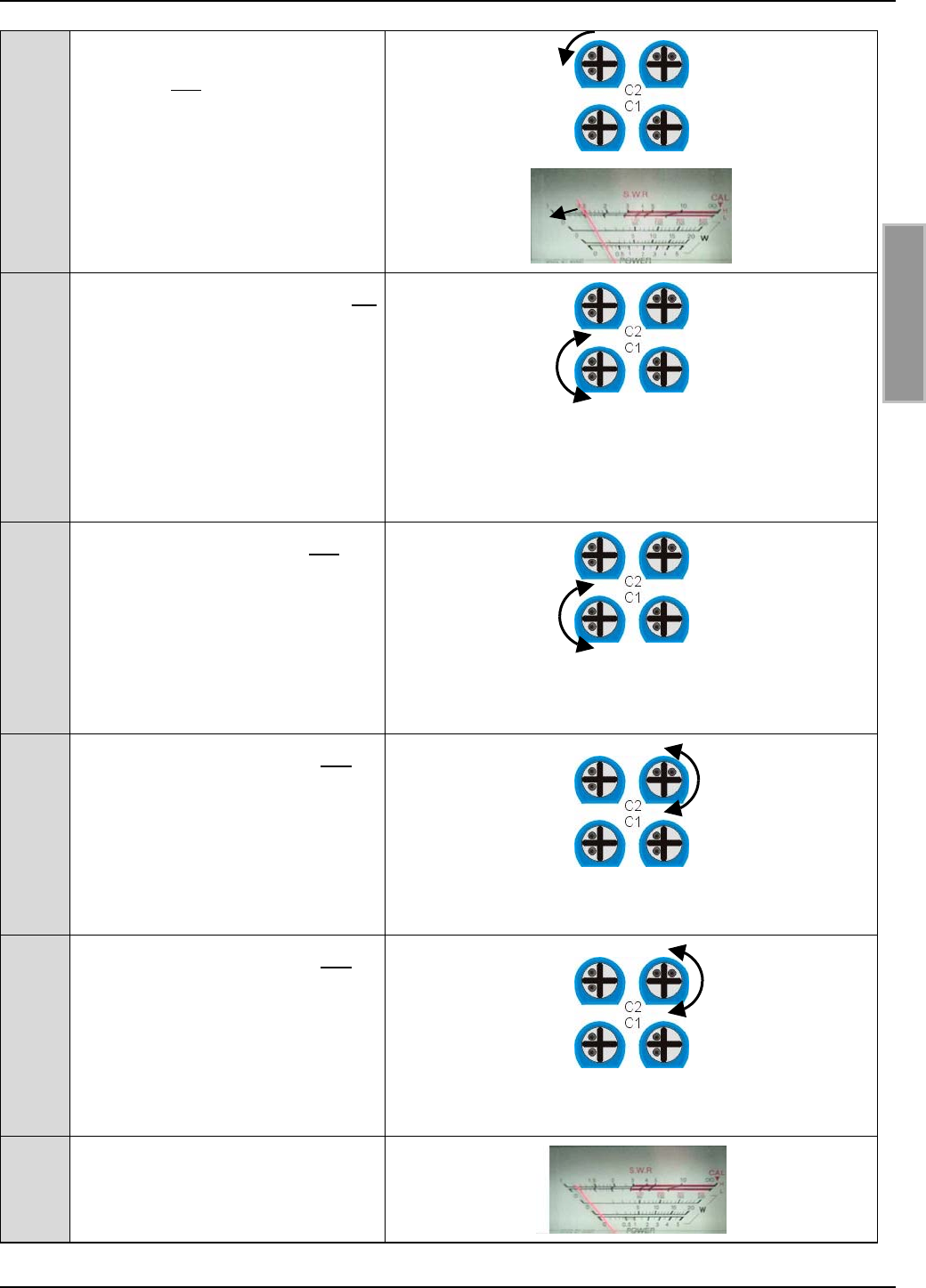
OBID®Installation ID ISC.ANT800/600
FEIG ELECTRONIC GmbH Page 61 of 75 M01004-2de-ID-B.doc
E N G L I S H
3Turn the leftmost of the two trim
capacitors C2 on Antenna 2 ap-
prox. ¼ turn counter-clockwise.
The SWR must drop !
Tune the SWR to the smallest
possible value.
4Turn the leftmost trim capacitor C1
on antenna 1 slowly counter-
clockwise.
The SWR must drop! Otherwise
turn the trim capacitor slowly
clockwise.
Continue tuning until the SWR
reading no longer drops.
5Turn the left trim capacitor C1 on
antenna 2 slowly counter-
clockwise.
The SWR must drop! Otherwise
turn the trim capacitor slowly
clockwise. Continue tuning until
the SWR reading no longer drops.
6Turn the right trim capacitor C2 on
antenna 1 (3) and Antenna 2 al-
ternately slowly counter-clockwise.
The SWR must drop! Otherwise
turn the trim capacitor slowly
clockwise. Continue tuning until
the SWR reading no longer drops.
7Turn the right trim capacitor C1 on
antenna 1 (3) and Antenna 2 al-
ternately slowly counter-clockwise.
The SWR must drop! Otherwise
turn the trim capacitor slowly
clockwise. Continue tuning until
the SWR reading no longer drops.
8Now the SWR reading should be
≤ 1.3:1

OBID®Installation ID ISC.ANT800/600
FEIG ELECTRONIC GmbH Page 62 of 75 M01004-2de-ID-B.doc
E N G L I S H
7.5 Tuning the complementary antenna
The configuration of a gate and instructions for tuning the base and complementary antenna in the
gate can be found in the mounting instructions for the ID ISC.SATC-A and in the Application Note:
Installation and tuning of a gate antenna with 1 m x 1 m read window in any desired label
orientation. Document: N10900-2e-ID-B.DOC. This document can be found on the OBID® i-scan
CD-ROM supplied by FEIG ELECTRONIC GmbH.
If a gate has been configured using a base and complementary antenna, you may use the Reader
and a smart label to check for correct function of the base antenna ID ISC.ANT800/600-A and the
complementary antenna ID ISC.ANT800/600-B. With both antennas having a transmitting power of
4W, the label 46 x 75 mm2 (ISO card size), the gate opening 1 m and a label orientation parallel to
the antenna facing out (outside the gate), a read range of 70-80 cm should be achieved
Otherwise you need to adjust the base antenna to an impedance of 50 Ω as described in Section
8.6 Measuring the standing wave ratio VSWR and check the noise level on the reader. Instructions
for checking the function of the complementary antenna can be found in Section 8.7 Measuring the
phase angle and checking antenna currents
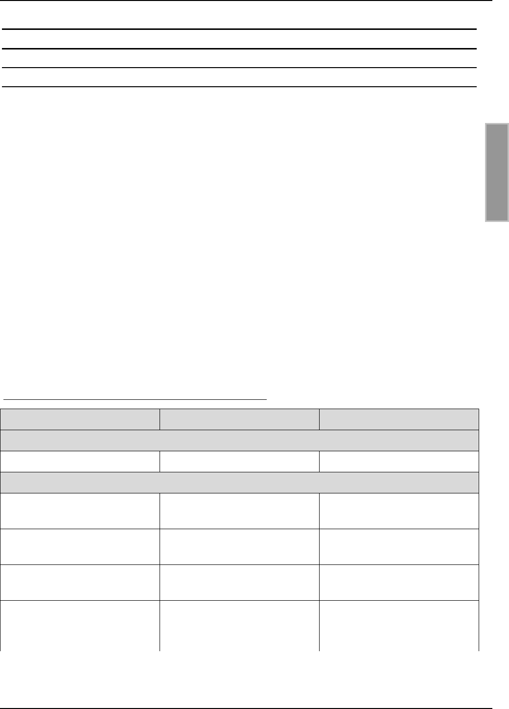
OBID®Installation ID ISC.ANT800/600
FEIG ELECTRONIC GmbH Page 63 of 75 M01004-2de-ID-B.doc
E N G L I S H
8. Startup
8.1 Radio regulatory agencies in EU countries and the USA
The design and RF power of the antennas is affected mainly by the country-specific RF regula-
tions. The entire EU geographic area is covered under uniform limits specified in the R&TTE
guideline and EN 300 330. In North America this is regulated by FCC Part 15.
In EU countries the maximum permissible field strength at 13.56 MHz at a distance of 10 m is:
42dBµA/m. In the USA this is 38dBµA/m.
When commissioning the system, be sure that the permissible values as prescribed by the national
regulatory agency are not exceeded.
Since FCC Part 15 prescribes a separation of 50 dB between the carrier and sidebands, the
Reader may be operated in the USA only using 1 of 256 bit coding (modulation).
When used with the Reader ID ISC.LR200 and under optimal ambient conditions, the antennas
may be operated in EU countries using the configurations described under 8.2 Special antenna
configurations at a maximum of 4.0 W in Europe and maximum 1.5 W in the USA If the prescribed
limit values are greater or less, the transmitting power must be adjusted accordingly or the
magnetic emission reduced by shielding the antenna.
When commissioning the antennas, the system integrator should be sure that the installation in-
structions are followed, the necessary Reader settings have been made and that the limit values
prescribed by the national regulatory agency are not exceeded.
Furthermore the Reader must be configured as follows:
Parameter Europe USA
General
RF-Power – CFG 3 4 W 1.5 W
ISO15693 Label
Downlink RF Modulation – CFG
8 / ISO-MODE / MOD
10 % 10%
Downlink RF Data coding –
CFG 8 / ISO-MODE / FAST
Fast (1/4) or Normal (1/256) Normal (1/256)
Timeslots - CFG 8 / ISO-MODE
/ NO-TS
16 Timeslots 16 Timeslots
Inventory Command Option –
CFG 8 / ISO-CMD-OPTION /
BREAK
Complete Timeslot length at
“NO TAG“
Complete Timeslot length at
“NO TAG“
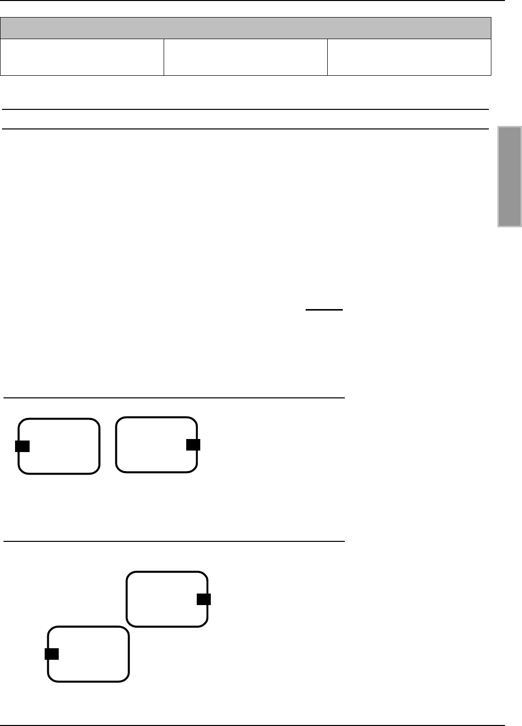
OBID®Installation ID ISC.ANT800/600
FEIG ELECTRONIC GmbH Page 64 of 75 M01004-2de-ID-B.doc
E N G L I S H
I-Code 1
Downlink RF Data coding –
CFG 8 / ICODE-MODE / FAST
Fast Mode (1/1) or Normal
Mode (1/256)
- Normal Mode (1/256)
8.2 Special antenna configurations
Radio type approval for the Reader ID ISC.LR200 is valid in EU countries and the USA for all
antennas which maintain the national limit values. The systems integrator must ensure this
when planning and constructing the system.
The limit value of 42dBµA/m prescribed by EN 300 330 for EU countries for magnetic emission at
13.56 MHz is maintained at 4 W of power using the ID ISC.ANT300/300 antenna. When using
larger single loop antennas the magnetic emission must be reduced using suitable means. This
can be accomplished for example by using shielding.
Another possibility is to compensate for the magnetic field by using a second antenna having an
opposing field direction.
This means however that the antennas must be arranged exactly as described. The anten-
nas must be connected to the ID ISC.ANT.PS Power Splitter or the ISC.ANT.T Transformer
as described in Section 5.1 Wiring options. The complete installation must be checked by
the system integrator to be sure maintain the national limit values.
1. Adjacent configuration of two base antennas ID ISC.ANT800/600-A
Antenna separation 10 cm
Max. transmitting power 4 W. series resistance 3 Ω
Both tuners (openings) of the antennas must face out
(left and right) and point in one direction. They must be
located in a single plane directly adjacent to each other.
2. Offset configuration with two base antennas ID ISC.ANT800/600-A.
Antenna separation (corners) 1 cm
Max. transmitting power 4 W. series resistance 3 Ω
Both tuners (openings) of the antennas must face out
(left and right) and point in one direction.
They must be located in a single plane directly adja-
cent to each other
See Application Note: Installation and tuning of a gate
antenna made from four base antennas. Document: N11000-2e-ID-B.DOC. This document can be
found on the OBID® i-scan CD-ROM supplied by FEIG ELECTRONIC GmbH.
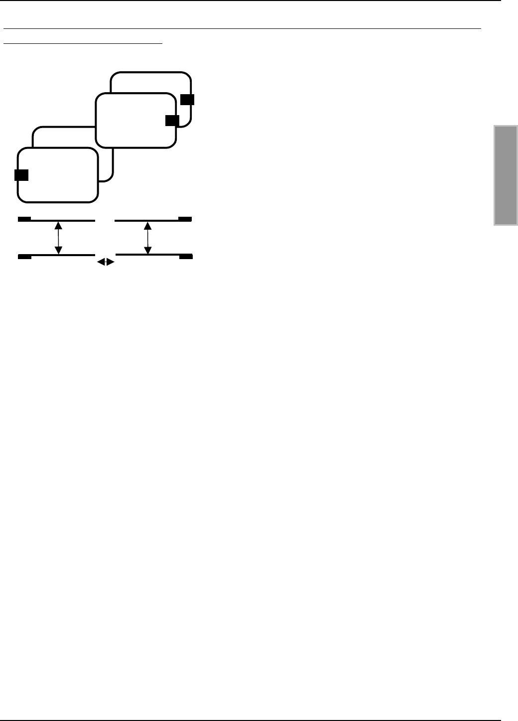
OBID®Installation ID ISC.ANT800/600
FEIG ELECTRONIC GmbH Page 65 of 75 M01004-2de-ID-B.doc
E N G L I S H
3. Configuration of a gate using two base antennas ID ISC.ANT800/600-A and two complementary
antennas ID ISC.ANT800/600-B.
Vertical offset of the antennas 1 cm, horizontal offset 10
cm
Max. transmitting power 4 W. series resistance 3 Ω
All antenna tuners (openings) must face out (left and
right). The openings (covers) should be oriented either in
the center of the gate or as drawn towards the outside.
The antennas must be in a single plane directly adjacent
to each other
For a description of these configuration see: Application
Note “Installation and tuning of a gate antenna with 1 m x
1 m read window in any desired label orientation.
Document: N10900-2e-ID-B.DOC. This document can be
found on the OBID® i-scan CD-ROM supplied by FEIG ELECTRONIC GmbH.
bb
a
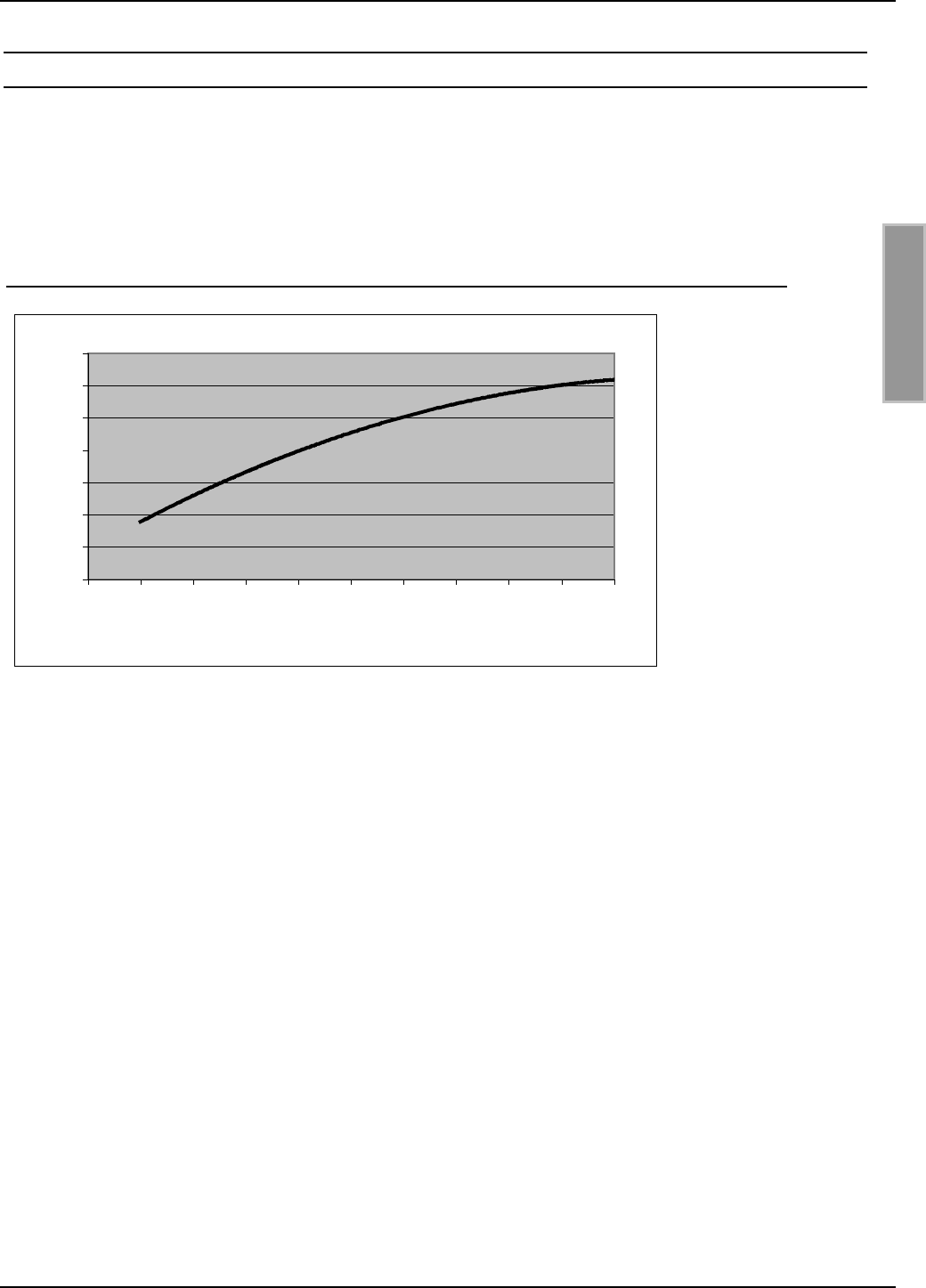
OBID®Installation ID ISC.ANT800/600
FEIG ELECTRONIC GmbH Page 66 of 75 M01004-2de-ID-B.doc
E N G L I S H
8.3 The effect of transmitting power on reading range
The reading range of an antenna depends on the antenna itself, the Reader, the smart label and
the transmitting power set for the Reader. Since the smart label receives its power from the mag-
netic field generated by the antenna and the field strength drops off sharply with increasing dis-
tance between the Reader and antenna, the emitted transmitting power for a given antenna has a
great influence on the read range.
Figure 29: Reading range* of an ID ISC.ANT800/600-A as a function of transmitting power
*Label 46 x 75 mm2, over the centre of the antenna, sensitivity / minimum operating field
Hmin=85mA/m rms, parallel orientation to the antenna.
A transmitting power above 8 W may, depending on ambient temperature, result in excessive
heating of the antenna and may destroy the antenna tuner.
60
65
70
75
80
85
90
95
012345678910
P [W]
Range [cm]
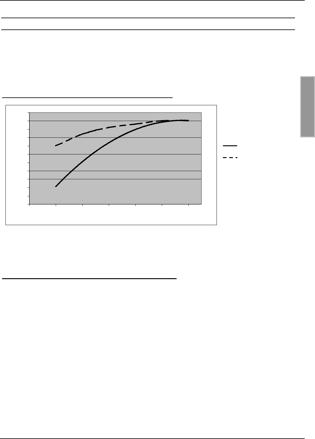
OBID®Installation ID ISC.ANT800/600
FEIG ELECTRONIC GmbH Page 67 of 75 M01004-2de-ID-B.doc
E N G L I S H
8.4 The effect of metal on reading range
Metal and other conducting materials cannot be penetrated by a magnetic field. The field lines and
inductance of the antenna are changed, which has a great effect on the effective range. The field is
also attenuated by mutual inductance and eddy currents in the metal.
The change in inductance can usually be compensated by using the tuning unit. Figure 30 shows
the effect of a metal plate on the antenna with (upper line) and without compensation.
Figure 30: Read range* as a function of proximity to metal
No compensation
Compensated
*Label 46 x 75 mm2, over the centre of the antenna, sensitivity / minimum operating field
Hmin=85mA/m rms, parallel orientation to the antenna,. transmitting power 4 W
If proximity to metal is unavoidable, note the following:
• Keep a minimum distance of 10 cm between metal and the antenna. Above 30 cm significant
read distance is sacrificed. Above 50 cm from metal there is no longer a measurable effect.
• The metal parts must not be permitted to form closed loops or circuits. These should be electri-
cally isolated at one point if necessary.
• The metal parts in direct proximity to the antenna should be grounded in star configuration with
a good HF connection.
30
35
40
45
50
55
60
65
70
75
80
85
0 102030405060
Distance to metal plate [cm]
Range [cm]
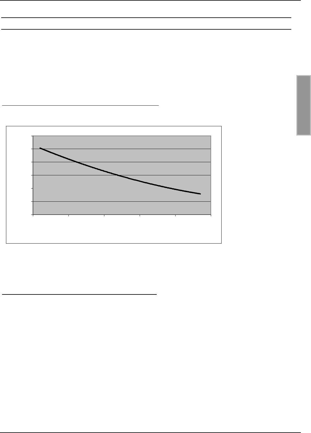
OBID®Installation ID ISC.ANT800/600
FEIG ELECTRONIC GmbH Page 68 of 75 M01004-2de-ID-B.doc
E N G L I S H
8.5 The effect of noise level on antenna reading range
In order for the smart label to be reliably read by the receiver even at low signal levels, you must
prevent or eliminate noise as much as possible. The amplitude of the noise levels can be checked
based on the noise level on the ID ISC.LR200 Reader. Critical are not the absolute measured val-
ues but the difference between Umax and Umin.
This has been simulated and graphically represented for 4 W transmitting power in the figure be-
low.
Figure 31: Reading range* as a function of noise level
*Label 46 x 75 mm2 over the centre of the antenna, sensitivity / minimum operating field
Hmin=85mA/m rms, parallel orientation to the antenna,. transmitting power 4 W
Good values for Umax-Umin with base antennas are 20mV, or 40mV for gate antennas.
Possible causes of excessively high noise levels:
• Poor (HF-) connections between Reader and antenna.
• Improper cable routing between antenna and Reader
• Poorly tuned antenna
• Noise signals from other electronic devices or transmitters.
• Noise in the Reader power supply
• Noise signals from other cables in the vicinity of the cable to and from the Reader
• Metal near the antenna
30
40
50
60
70
80
90
0 100 200 300 400 500
Umax-Umin [mV]
Range [cm]
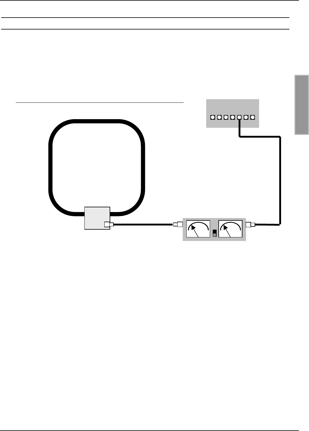
OBID®Installation ID ISC.ANT800/600
FEIG ELECTRONIC GmbH Page 69 of 75 M01004-2de-ID-B.doc
E N G L I S H
8.6 Measuring the standing wave ratio VSWR
Once an antenna has been calibrated or the local conditions have changed, the question arises:
How well are the Reader and base antenna adjusted to each other? A useful tool for evaluating the
adjustment of the antenna to the impedance of 50 Ω is the VSWR meter. This device measures the
ratio between outgoing and reflected energy. A VSWR of up to 1.3:1 is considered a good value. A
wattmeter is often integrated into these devices.
The cable between the Reader and the SWR meter should either be very short (< 20 cm) or 7.20
m (RG 58=Lambda/2) long. If the VSWR is greater than 1.3:1 after tuning, use trim capacitors C1
and C2 on the board of the base antenna to perform a slight adjustment.
Furthermore the VSWR meter can be used at any time to check the tuning of the base antennas. If
changes in local conditions result in detuning of the antennas, this can be verified whenever
desired.
In addition to the losses indicated by the SWR due to mismatching between the cable and the
antenna, it happens that the Reader drives different output currents depending on the antenna
impedance, resulting in power variance. This means that at 50 Ω a current of approx. 0.3 A flows.
No current flows when an output is open, and when there is a short circuit the current is limited to
approx. 1.0 A. Matching the antenna also has a slight effect on the noise levels.
Base antenna
ID ISC.
A
NT800/600
SWR / Power Meter
Reader
ID ISC.LR200
Figure 32: Inserting a VSWR meter into the antenna cable
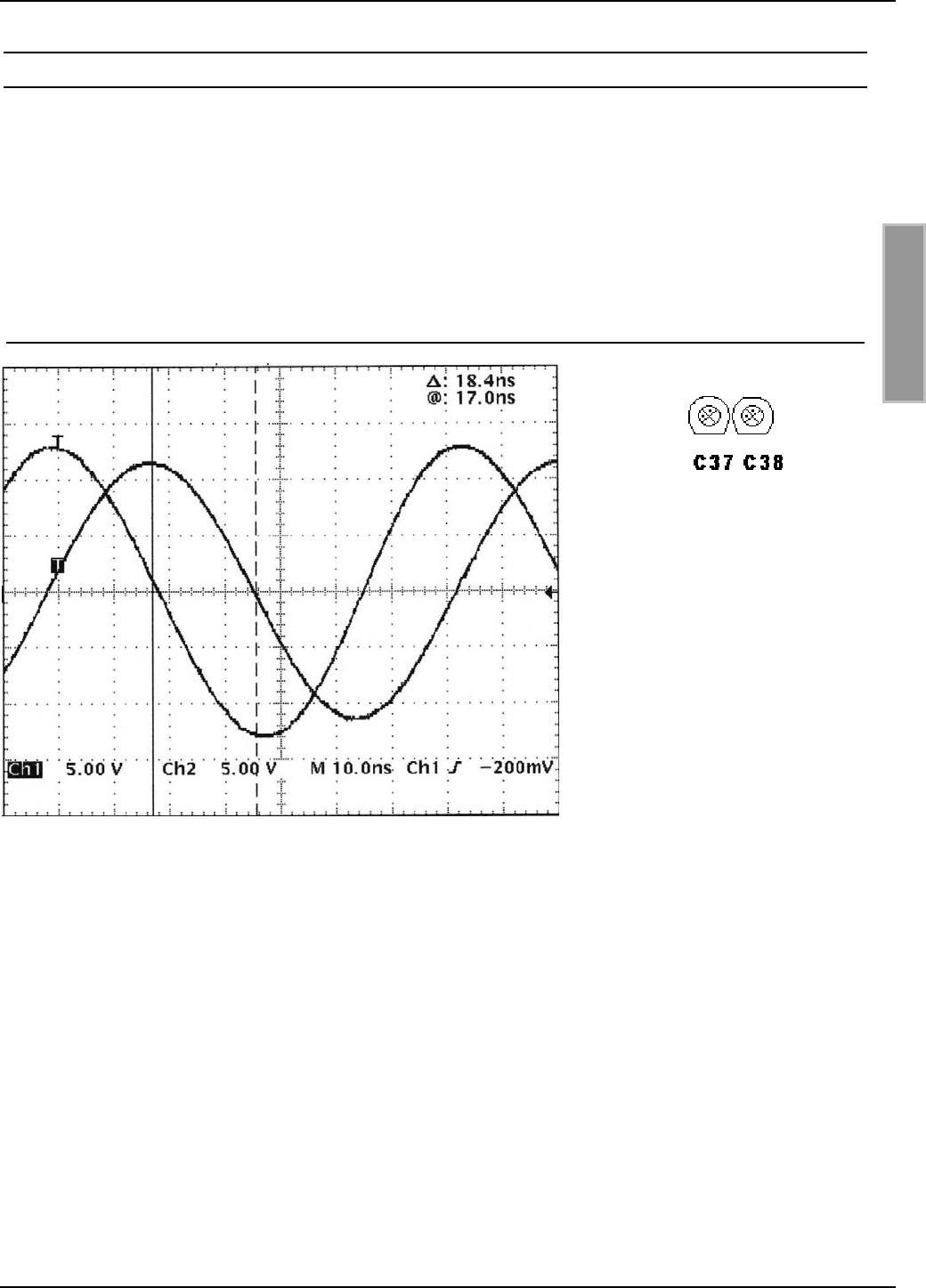
OBID®Installation ID ISC.ANT800/600
FEIG ELECTRONIC GmbH Page 70 of 75 M01004-2de-ID-B.doc
E N G L I S H
8.7 Measuring the phase angle and checking antenna currents
To check or fine adjust the phase angle between the base and complementary antenna, use an
oscilloscope and 2 small test loops made of wire to measure the phase angle. AT 13.56 MHz and a
phase shift of 90° between the base and complementary antenna, the time delay will be 18.4 ns.
Bild 16 shows a printout of this measurement.
Use trim capacitors C37 and C38 to correct the phase of the currents between the two antennas.
After tuning the two associated trim capacitors C37 and C38 should be set to approximately the
same capacitance.
Figure 33: Phase difference between base and complementary antenna Figure 34: Same C values
If the adjustment range of the
trim capacitors is not sufficient,
set for the best possible phase
value. Now both trim capacitors
must be set their minimum or
maximum. Then turn the
capacitors 180°, from either their
minimum or maximum. Now you
must recalibrate the antennas
using the ID ISC.SAT.C
controller. Then you will have double the adjustment range available.
Furthermore the antenna current in both antennas making up a gate should be the same. This can
be checked by measuring the amplitude and corrected by changing the serial resistors R (JP8,
JP1-4).
If both currents are the same, the RF power of the Reader will be distributed evenly between both
antennas. This means that in a gate consisting of two antennas and at a RF power of 8 W, both
antennas will operate at 4 W.
Important: Both test loops must be the same size, have the same cable length, be attached at the
same antenna position, and be exactly parallel to each other. In addition, they should be attached
as close to the center of the antenna surface as possible.

OBID®Installation ID ISC.ANT800/600
FEIG ELECTRONIC GmbH Page 71 of 75 M01004-2de-ID-B.doc
E N G L I S H
9. Technical Data for ID ISC.ANT800/600-A and ID ISC.ANT800/600-B
Mechanical Data
• Housing Plastic (ABS)
• Dimensions ( w x h x d ) 852 mm x 620 mm x 40 mm ± 1 mm
• Weight
– ID ISC.ANT800/600-A
– ID ISC.ANT800/600-B
approx. 2.7 kg
approx. 2.5 kg
• Enclosure rating IP 65
• Color Black
Electrical Data
• Max. transmitting power 8 W
• Admissible transmitting power
– EU (according EN 300 330)
– U.S. (according FCC Part 15)
4.0 W
1.5 W
• Operating frequency 13.56 MHz
• Range Max. 80 cm*
• Antenna connection 1 x SMA plug (50 Ω)
• Antenna connector cable RG58, 50 Ω, approx. 3.6 m long
Ambient
• Temperature range
– Operating
– Storage
–25°C to +55°C
–25°C to +60°C
• Vibration EN60068-2-6
10 Hz to 150 Hz :0.075 mm / 1 g
• Shock EN60068-2-27
Acceleration : 30 g

OBID®Installation ID ISC.ANT800/600
FEIG ELECTRONIC GmbH Page 72 of 75 M01004-2de-ID-B.doc
E N G L I S H
Applicable Norms
• EMC EN 300 683
• Safety
– Europe
– USA
EN 60950 (on request)
UL 1950 (on request)
*Label 46 x 75 mm2, over the centre of the antenna, sensitivity / minimum operating field
Hmin=85mA/m rms, parallel orientation to the antenna,. transmitting power 4 W.
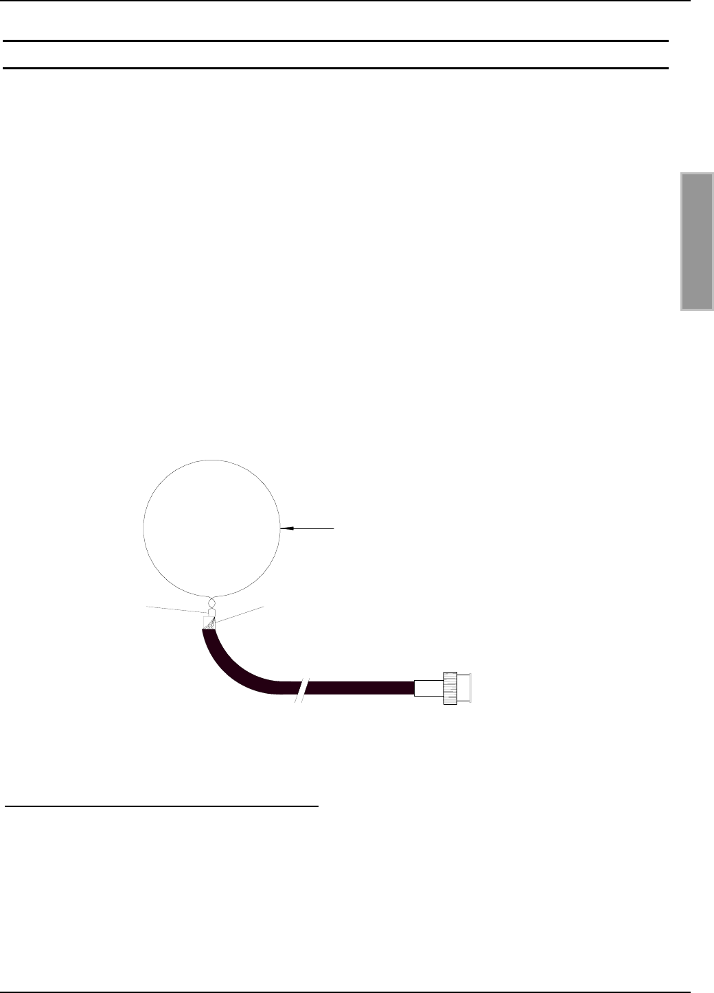
OBID®Installation ID ISC.ANT800/600
FEIG ELECTRONIC GmbH Page 73 of 75 M01004-2de-ID-B.doc
E N G L I S H
10. Appendix: Helpful tools for constructing and testing the antennas
The following equipment is recommended for tuning, troubleshooting and commissioning the an-
tennas:
• Laptop or personal computer (PC) running under Microsoft Windows 95, 98, ME, 2000, XP.
• Service software ISCStart (V4.02 or higher). This software can be found on the OBID® i-scan
CD-ROM supplied by FEIG ELECTRONIC GmbH..
• SWR and Power Meter including SMA connectors (female) or appropriate adapters.
• Qty. 1 cable RG 58 C/U approx. 20 – 25 cm (7.8 – 9.8 in) long with two male SMA plugs (gen-
erally self-assembled).
• Suitable screwdriver for antenna tuning, with plastic blade, 2.4x0.5mm.
• 2-channel oscilloscope, sweep rate at least 10ns/Div or analog bandwidth of 100 MHz.
• Qty. 2 test loops 1.5 m long (consisting of 50 Ohm, RG58 cable with BNC plug and wire loop
(diameter approx. 75 mm [30 in]) at the other end (generally self-assembled).
The following tools are optional but helpful:
• HF Impedance Analyzer (for 13.56 MHz)
screen
centre conductor
BNC-plug, male
RG58 cable 2,5 m
ø 75

OBID®Installation ID ISC.ANT800/600
FEIG ELECTRONIC GmbH Page 74 of 75 M01004-2de-ID-B.doc
E N G L I S H
10.1 Recommended equipment and possible sources:
1. VSWR – Meter
Alan CTE International VSWR & Power – Meter KW 220
Vendors:
• CB Funkshop Rößner, 91637 Wörnitz, Tel.09868/932945, http://www.cb-funkshop.de
• Garant – Funk, 53879 Euskirchen, Tel. 02251/55757
Alan CTE International VSWR and Wattmeter K155
Vendor:
• Conrad Electronic
1. Antenna analyzer
MFJ HF/UHF SWR Analyzer
• Model MFJ-259B, 1.8 – 170 MHz
Vendors:
• Austin Amateur Radio Supply, USA 1-800 423 2604
• VHT – Impex, Ecke, Germany, Tel.: 05224/9709-0
CIA – HF Complex Impedance Analyzer 5012 – 5000
Vendors:
• AEA, Vista, California 92083, USA
• Garant – Funk, 53879 Euskirchen, Tel. 02251/55757
2. Adapter : UHF-> BNC, BNC-SMA, SMA-SMA, Abschlußwiderstand 50 Ω
Vendors:
• Bürklin OHG, http://www.buerklin.com
• Conrad.com AG, http://www.conrad.de
• Farnell Electronic Components GmbH, 82041 Oberhaching, http://www.farnell.com
3. Amber / Tuning screwdrivers with plastic blade
Blade size: 2,4x0,5mm
Vendors:
• Bürklin Bestellnummer 06 L 8364

OBID®Installation ID ISC.ANT800/600
FEIG ELECTRONIC GmbH Page 75 of 75 M01004-2de-ID-B.doc
E N G L I S H
4. Oscilloscope
Tektronix TDS 210 or a model from the TDS2xx or TDS3xx. series
Agilent 54622D or a model from the 546xx series
Voltcraft 100 MHz- Oscilloskope 6100
Hameg HM 407 or HM 1507-3
Vendors:
• Tektronix Inc, http://www.tektronix.de oder http://www.tektronix.com
• Agilent Technoligies, http://www.agilent.com
• Conrad Electronic GmbH, 92240 Hirschau, http://www.conrad.de
• ELV Elektronik AG 26787 Leer, http://www.elv.de oder http://www.elv.com
• DataTec GmbH, 72770 Reutlingen, http://www.datatec.com
5. EMC ferrite toroid cores
Diameter da=28, di=16, I=20, B.Nr.742 701 4
Diameter da=40,6 di=27,4 I=15, B.Nr.742 701 5
Vendor
Würth Elektronik GmbH & Co.KG
Riedenstraße 16
74635 Kupferzell
Tel.: 07944 / 91 93 0
www.wuerth.de oder www.wuerth.com