Fluke Electronics VERSIV2 CableAnalyzer User Manual Verisiv Part 1
Fluke Electronics CableAnalyzer Verisiv Part 1
Contents
- 1. User Manual DSX 302
- 2. User Manual Statement
- 3. User Manual Verisiv Part 1
- 4. User Manual Verisiv Part 2
- 5. User Manual Verisiv Part 3
User Manual Verisiv Part 1

May 2017
©2017 Fluke Corporation
All product names are trademarks of their respective companies.
Versiv™ 2
Cabling Certification Product Family
Users Manual
Versiv Software Version 5.1
LIMITED WARRANTY AND LIMITATION OF LIABILITY
Each Fluke Networks product is warranted to be free from defects in material and
workmanship under normal use and service unless stated otherwise herein. The
warranty period for the mainframe is one year and begins on the date of purchase.
Parts, accessories, product repairs and services are warranted for 90 days, unless
otherwise stated. Ni-Cad, Ni-MH and Li-Ion batteries, cables or other peripherals are all
considered parts or accessories. The warranty extends only to the original buyer or end
user customer of a Fluke Networks authorized reseller, and does not apply to any
product which, in Fluke Networks’ opinion, has been misused, abused, altered,
neglected, contaminated, or damaged by accident or abnormal conditions of
operation or handling. Fluke Networks warrants that software will operate
substantially in accordance with its functional specifications for 90 days and that it has
been properly recorded on non-defective media. Fluke Networks does not warrant
that software will be error free or operate without interruption.
Fluke Networks authorized resellers shall extend this warranty on new and unused
products to end-user customers only but have no authority to extend a greater or
different warranty on behalf of Fluke Networks. Warranty support is available only if
product is purchased through a Fluke Networks authorized sales outlet or Buyer has
paid the applicable international price. To the extent permitted by law, Fluke
Networks reserves the right to invoice Buyer for repair/replacement when a product
purchased in one country is submitted for repair in another country.
For a list of authorized resellers, visit www.flukenetworks.com/wheretobuy.
Fluke Networks warranty obligation is limited, at Fluke Networks option, to refund of
the purchase price, free of charge repair, or replacement of a defective product which
is returned to a Fluke Networks authorized service center within the warranty period.
To obtain warranty service, contact your nearest Fluke Networks authorized service
center to obtain return authorization information, then send the product to that
service center, with a description of the difficulty, postage and insurance prepaid (FOB
destination). Fluke Networks assumes no risk for damage in transit. Following
warranty repair, the product will be returned to Buyer, transportation prepaid (FOB
destination). If Fluke Networks determines that failure was caused by neglect, misuse,
contamination, alteration, accident or abnormal condition of operation or handling,
or normal wear and tear of mechanical components, Fluke Networks will provide an
estimate of repair costs and obtain authorization before commencing the work.
Following repair, the product will be returned to the Buyer transportation prepaid and
the Buyer will be billed for the repair and return transportation charges (FOB Shipping
point).
THIS WARRANTY IS BUYER’S SOLE AND EXCLUSIVE REMEDY AND IS IN LIEU OF ALL
OTHER WARRANTIES, EXPRESS OR IMPLIED, INCLUDING BUT NOT LIMITED TO ANY
IMPLIED WARRANTY OF MERCHANTABILITY OR FITNESS FOR A PARTICULAR PURPOSE.
FLUKE NETWORKS SHALL NOT BE LIABLE FOR ANY SPECIAL, INDIRECT, INCIDENTAL OR
CONSEQUENTIAL DAMAGES OR LOSSES, INCLUDING LOSS OF DATA, ARISING FROM
ANY CAUSE OR THEORY.
Since some countries or states do not allow limitation of the term of an implied
warranty, or exclusion or limitation of incidental or consequential damages, the
limitations and exclusions of this warranty may not apply to every buyer. If any
provision of this Warranty is held invalid or unenforceable by a court or other decision-
maker of competent jurisdiction, such holding will not affect the validity or
enforceability of any other provision.
4/15
Fluke Networks
PO Box 777
Everett, WA 98206-0777
USA
i
Contents
Chapter 1 Get Acquainted
Overview of Features ......................................................1
Contact Fluke Networks .................................................2
Register Your Product ....................................................2
Additional Resources ......................................................2
Supplements and Updated Manuals .............................3
Kit Contents ....................................................................3
Symbols ............................................................................3
WSafety Information ....................................................5
For the Versiv 2 Main Unit .......................................5
For DSX Modules ......................................................7
For CertiFiber Pro OLTS Modules .............................8
For OptiFiber Pro OTDR Modules ............................10
AC Adapter and Battery .................................................11
Charge the Battery ...................................................11
Check the Battery Status ..........................................12
Verify Operation .............................................................13
How to Use the Touchscreen .........................................15
Change the Language ....................................................17
Buttons to Do Tests and Save Results ............................17
Overview of Memory Functions .....................................19
Options for Cable IDs ......................................................19
How to Install a Strap .....................................................21
How to Remove or Install a Module ..............................21

ii
Versiv 2 Cabling Certification Product Family
Users Manual
About LinkWare Applications ....................................... 23
LinkWare PC Cable Test Management Software ... 23
The LinkWare Live Web Application ...................... 23
LinkWare Stats ......................................................... 23
Chapter 2 Certify Twisted Pair Cabling
Overview of Features ..................................................... 25
Connectors, Keys, and LEDs ........................................... 26
About Link Interface Adapters ...................................... 30
Adapters for DSX-8000 and DSX-5000 Modules ........... 32
The DSX CableAnalyzer Home Screen .......................... 33
Make Sure Your Tester is Ready to Certify
Cabling ............................................................................ 36
Set the Reference ........................................................... 36
Settings for Twisted Pair Tests ....................................... 38
How to Do an Autotest .................................................. 43
“Bad Patch Cord” Message ............................................ 47
How to Certify Patch Cords ........................................... 48
Twisted Pair Autotest Results ........................................ 48
Automatic Diagnostics ............................................. 49
PASS*/FAIL* Results ................................................. 51
WIRE MAP Tab ......................................................... 52
PERFORMANCE Tab ................................................. 54
Frequency-Domain Results ...................................... 55
How to Save Frequency-Domain Results
as a Plot or a Table ............................................ 55
DIAGNOSTIC and FAULT INFO Tabs ........................ 60
Continuous Tests ...................................................... 60
Long-Range Communication Mode (DSX-5000) ........... 61
About the AxTalk Analyzer Kit ..................................... 61

Contents
iii
Chapter 3 Certify Coaxial Cabling
Set the Reference for Coaxial Tests ............................... 63
Settings for Coaxial Tests ............................................... 65
How to Do an Autotest .................................................. 67
Coaxial Autotest Results ................................................ 70
About Splitters ................................................................ 71
Tests Without a Remote ................................................. 72
Continuous Tests ............................................................ 74
Chapter 4 Clean Fiber Endfaces
Always Clean Endfaces Before Tests ............................. 75
How to Use a Fluke Networks Quick Clean
Cleaner ............................................................................ 78
How to Use Wipes, Swabs, and Solvent ........................80
To Clean Bulkhead Connectors ............................... 80
To Clean the Optical Connectors on the
Modules .................................................................... 81
To Clean Fiber Adapters .......................................... 81
To Clean Connector Ends ........................................ 81
Chapter 5 Inspect Fiber Endfaces
Connectors, Keys, and LEDs ........................................... 84
Settings for FiberInspector Tests ................................... 86
How to Do the FiberInspector Test ............................... 87
Automatic Analysis of Scratches and Defects ............... 92
Fiber Tests with Two Main Testers ................................ 94
Chapter 6 Certify Fiber Cabling
Overview of Features ..................................................... 95
Connectors, Keys, and LEDs ........................................... 96

iv
Versiv 2 Cabling Certification Product Family
Users Manual
How to Remove and Install the Connector
Adapters ......................................................................... 100
The CertiFiber Pro Home Screen ................................... 102
Requirements for Reliable Fiber Test Results ............... 105
About the Reference for Fiber Tests ....................... 106
When to Set the Reference .............................. 106
Good Reference Values ..................................... 107
How to See the Reference Values .................... 107
About Test Reference Cords and Mandrels ............ 108
About the EF-TRC (Encircled-Flux
Test Reference Cords) ....................................... 108
About APC Connectors ...................................... 110
About Standard Mandrels ................................ 112
Settings for Fiber Tests ................................................... 112
About 1 Jumper Reference Connections ...................... 120
Autotest in Smart Remote Mode .................................. 121
Fiber Tests with Two Main Testers .......................... 121
Step 1: Set the Reference in Smart Remote
Mode ........................................................................ 123
Step 2: Measure the Loss of the Test
Reference Cord You Will Add ................................. 125
Step 3: Do an Autotest in Smart Remote
Mode ........................................................................ 126
Autotest Results for Smart Remote Mode ............. 127
Fiber IDs for Saved Results in Smart Remote
Mode ........................................................................ 129
Autotest in Loopback Mode .......................................... 129
Step 1: Set the Reference in Loopback Mode ........ 131
Step 2: Measure the Loss of the Test
Reference Cord You Will Add ................................. 133
Step 3: Do an Autotest in Loopback Mode ............ 134

Contents
v
Autotest Results for Loopback Mode ..................... 135
Autotest in Far End Source Mode ................................. 137
Auto Wavelength Modes ........................................137
Step 1: Set the Reference in Far End Source
Mode ........................................................................ 139
Step 2: Measure the Loss of the Test
Reference Cord You Will Add ................................. 142
Step 3: Do an Autotest in Far End Source
Mode ........................................................................ 143
Autotest Results for Far End Source Mode ............. 144
Bi-Directional Tests ......................................................... 146
Chapter 7 Use the OTDR
Overview of Features ..................................................... 149
Connectors, Keys, and LEDs ........................................... 150
How to Remove and Install the Connector
Adapters .......................................................................... 152
The OptiFiber Pro Home Screen .................................... 154
Settings for OTDR Tests .................................................. 156
About Launch and Tail Cords ........................................160
How to Prevent Damage to the Launch Cord
Connectors ............................................................... 162
How to Hang the Launch Cords .............................. 162
OTDR Port Connection Quality ...................................... 163
How to Do an OTDR Test ............................................... 165
OTDR Results ................................................................... 169
EventMap ................................................................. 169
Event Table ............................................................... 174
OTDR Trace ............................................................... 176
The FaultMap Test .......................................................... 178
How to Do the FaultMap Test ................................. 179

vi
Versiv 2 Cabling Certification Product Family
Users Manual
FaultMap Screen ...................................................... 182
The SmartLoop Test ....................................................... 184
How To Do an Auto SmartLoop Test ...................... 186
Set up the launch compensation function ....... 186
Do the SmartLoop test ...................................... 188
SmartLoop Results ................................................... 190
Bi-Directional SmartLoop Tests ............................... 191
How to Do a Bi-Directional SmartLoop Test .......... 191
Set up the launch compensation function ....... 191
Do the SmartLoop test ...................................... 193
Averaged Bi-Directional Results .............................. 195
Chapter 8 Use the Visual Fault Locator
Visual Fault Locator Applications .................................. 199
How to Use the VFL ........................................................ 200
Chapter 9 Monitor Optical Power
How to Monitor Power and Loss ................................... 203
How to Control the Light Source .................................. 207
Use the Display to Control the Main
Tester’s Light Source ................................................ 208
Use the Module’s Button to Control the Light
Source ....................................................................... 208
Chapter 10 Manage Test Results
View Saved Results ......................................................... 211
How to Add a Result to a Saved Result ........................ 215
How to Replace a Saved Result that Failed .................. 216
Delete, Rename, and Move Results ............................... 216
Manage Results on a Flash Drive ................................... 218

Contents
vii
Upload Results to a PC ................................................... 219
View the Memory Status ................................................ 220
Chapter 11 Use Projects
Why Use Projects? .......................................................... 221
Set Up a Project .............................................................. 222
The PROJECT Screen ....................................................... 222
The CABLE ID SETUP Screen ........................................... 225
About Next ID Sets ......................................................... 225
Manage Projects on a Flash Drive ................................. 228
Copy Project Settings to Other Testers ......................... 229
Chapter 12 Sync Projects with LinkWare™ Live
Sign Up for a LinkWare Live Account ........................... 231
How to See the Tester’s MAC Address .......................... 232
Use LinkWare Live Through a Wired Ethernet
Network .......................................................................... 232
Use LinkWare Live Through a Wi-Fi Ethernet
Network .......................................................................... 233
Change the Network Settings ....................................... 236
Settings for the Wired Port ..................................... 236
Settings for Wi-Fi ..................................................... 236
Delete Wi-Fi Settings and Passwords ...................... 238
About the Asset Management Service .......................... 238
Sign Your Tester Out of LinkWare Live ......................... 238
Sign In to LinkWare Live from a Desktop or
Mobile Device .......................................................... 239
Import Projects from LinkWare Live i
nto LinkWare PC ............................................................. 239
Learn More About LinkWare Live ................................. 239

viii
Versiv 2 Cabling Certification Product Family
Users Manual
Chapter 13 Maintenance
Verify Operation ............................................................ 242
Clean the Tester ............................................................. 242
Clean the FI-1000 Video Probe ...................................... 242
See Information About the Tester ................................ 243
Traceable Calibration Period ......................................... 243
Update the Software ..................................................... 243
Use a PC to Update the Software ........................... 244
Use an Updated Main Tester to Update Other
Testers ....................................................................... 246
Use LinkWare Live to Update the Software ........... 248
Update the Software in a Module .......................... 248
Extend the Life of the Battery ....................................... 249
Store the Tester .............................................................. 249
Remove the Battery ....................................................... 250
If the Tester Does Not Operate as Usual ....................... 250
Options and Accessories ................................................ 251
Appendix A: Reference Method Names
Appendix B: Modified 1 Jumper Reference Method
ix
List of Figures
Figure Page
1. LEDs Show the Remote’s Battery Status ........................ 12
2. Connections to See the Status of a Remote’s Battery... 14
3. How to Zoom the Screen ................................................ 16
4. FIX LATER, TEST AGAIN, and TEST Buttons and
the TEST Key .................................................................... 17
5. How to Install a Strap and Use the Hand Strap............. 21
6. How to Remove and Install a Module ........................... 22
7. Main Tester Connectors, Keys, and LEDs ....................... 26
8. Remote Tester Connectors, Keys, and LEDs................... 28
9. How to Attach and Remove Link Interface Adapters ... 30
10. How to Prevent Damage to the Permanent
Link Adapter Cables ........................................................ 31
11. DSX-8000 and DSX-5000 Module and Adapter
Differences....................................................................... 32
12. The Home Screen for the DSX CableAnalyzer............... 33
13. Reference Connections for Twisted Pair Cable ............. 37
14. Outlet Configurations..................................................... 42
15. Equipment for Autotests on Twisted Pair Cable ........... 43
16. Permanent Link Connections for Links Up to Cat 7A ..... 45
17. Channel Connections for Links Up to Cat 7A..................... 46
18. Permanent Link Connections for Cat 8/Class I Links...... 46
19. Channel Connections for Cat 8/Class I Links .................. 47
20. Examples of Fault Information Screens ......................... 50
21. PASS* and FAIL* Results ................................................. 51
22. WIRE MAP Tab................................................................. 52

x
Versiv 2 Cabling Certification Product Family
Users Manual
23. PERFORMANCE Tab .........................................................54
24. Tabular Results Screen for a Frequency-Domain Test ...56
25. Plot Screen for a Frequency-Domain Test ......................58
26. BV179.EPSReference Connections for Tests on Coaxial
Cabling .............................................................................64
27. Equipment for Tests on Coaxial Cabling ........................67
28. Examples of Connections for Tests on Coaxial Cabling.69
29. Autotest Results for Coaxial Cabling..............................70
30. Connections for Coaxial Tests Without a Remote .........73
31. Examples of Clean and Dirty Fiber Endfaces..................75
32. Equipment to Clean and Inspect Fiber Endfaces ...........77
33. How to Use the One Click Cleaner .................................79
34. Connectors, Keys, and LEDs ............................................84
35. Equipment for the FiberInspector Test ..........................87
36. How to Use the FI-1000 Probe ........................................89
37. How to Use the Optional MPO/MTP® Inspection Tip.....89
38. FiberInspector Image with Manual Grading Selected...90
39. FiberInspector Image with Defect Analysis....................93
40. Main Tester Connectors, Keys, and LEDs
(CFP-QUAD module shown) ............................................96
41. Remote Tester Connectors, Keys, and LEDs
(CFP-QUAD module shown) ............................................98
42. How to Remove and Install the Connector Adapters....101
43. The Home Screen for CertiFiber Pro Modules................102
44. How to Prevent Damage to the EF-TRC Fiber Cables ....109
45. TRCs Necessary for Links with APC Connectors..............111
46. Screen to Set the Number of Connectors,
Splices, and Jumpers ........................................................117
47. How to Count the Numbers of Connectors,
Splices, and Jumpers ........................................................119

List of Figures
xi
48. Equipment for Autotests in Smart Remote Mode ........ 122
49. Connections for Smart Remote Mode
(1 Jumper Reference, Multimode Fiber) ........................ 124
50. Result for Smart Remote Mode
(Unsaved Bi-Directional Results Shown) ........................ 128
51. Equipment for Autotests in Loopback Mode ................ 130
52. Connections for Loopback Mode
(1 Jumper Reference, Multimode Fiber) ........................ 132
53. Result for Loopback Mode ............................................. 135
54. Equipment for Autotests in Far End Source Mode ....... 138
55. Connections for Far End Source Mode
(1 Jumper Reference Multimode Fiber) ......................... 141
56. How to Turn on the Remote’s Optical Source............... 142
57. Result for Far End Source Mode..................................... 145
58. Connectors, Keys, and LEDs
(OptiFiber Pro Quad OTDR shown) ................................ 151
59. How to Remove and Install the Connector Adapters ... 153
60. The Home Screen ............................................................ 154
61. How to Prevent Damage to the Launch
Cord Connectors.............................................................. 162
62. How to Use the Optional TPAK Magnetic Hanger........ 163
63. The OTDR Port Connection Quality Gauge
and Progress Screen ........................................................ 164
64. Equipment for OTDR Tests ............................................. 165
65. OTDR Connected with a Launch Cord ........................... 166
66. OTDR Connected with Launch and Tail Cords............... 167
67. OTDR Connected to a Spool of Fiber ............................. 168
68. EventMap Example 1 ...................................................... 170
69. EventMap Example 2 ...................................................... 173
70. Event Table ...................................................................... 175
71. OTDR Trace ...................................................................... 176

xii
Versiv 2 Cabling Certification Product Family
Users Manual
72. Equipment for FaultMap Tests .......................................180
73. FaultMap Test Connections.............................................181
74. FaultMap Screen ..............................................................182
75. Equipment for SmartLoop Tests .....................................185
76. SmartLoop Launch Compensation Connections ............187
77. SmartLoop Test Connections ..........................................189
78. EventMap from a SmartLoop Test ..................................190
79. SmartLoop Test Connections for a Bi-Directional Test..194
80. EventMap for Averaged, Bi-Directional SmartLoop
Results ..............................................................................196
81. Equipment for Visual Fault Locator Tests ......................200
82. How to Use the Visual Fault Locator ..............................202
83. Equipment for Power Meter Measurements .................204
84. Connections to Monitor Power and Loss .......................205
85. Power Meter Measurements and Controls ....................206
86. Light Source Controls for the Main Tester .....................209
87. RESULTS Screen ................................................................212
88. How to Connect the Tester to a PC ................................220
89. PROJECT Screen ...............................................................223
90. CABLE ID SETUP Screen
(after you enter the first and last IDs)............................226
91. SYNC PROJECTS Screen....................................................235
92. How to Connect the Tester to a PC ................................245
93. How to Connect Units Together to
Update the Software .......................................................247
94. How to Remove the Battery ...........................................250
B-1. Modified 1 Jumper Reference Method for
Smart Remote Mode .......................................................256
1
Chapter 1: Get Acquainted
Overview of Features
The Versiv™ 2 main and remote units are rugged, hand-held
instruments that you configure to certify, troubleshoot, and
document copper and fiber optic cabling. The Versiv 2 platform
includes these features:
Operates with DSX CableAnalyzer™ modules to certify twisted
pair cabling. See Chapter 2.
Operates with CertiFiber® Pro Optical Loss Test Set (OLTS)
modules to measure optical power loss and length on dual-
fiber, multimode and singlemode cabling. See Chapter 6.
Operates with OptiFiber® Pro OTDR modules to locate,
identify, and measure reflective and loss events in multimode
and singlemode fibers. See Chapter 7.
The optional FI-1000 FiberInspector™ video probe connects to
the type A USB port on the Versiv 2 main unit to let you
inspect the endfaces in fiber optic connectors. See Chapter 5.
Gives a PASS or FAIL result based on a test limit that you
specify.
Taptive™ user interface lets you quickly navigate through
different views of the results and see more information about
cables.
ProjX™ management system lets you set up projects to specify
the types of tests and the cable IDs necessary for a job and
monitor the progress and status of the job.
You can connect the tester to a wired or Wi-Fi network and
use the LinkWare™ Live web application to manage your
projects from a desktop or mobile device.
LinkWare PC software lets you upload test results to a PC and
make professional-quality test reports.

Versiv 2 Cabling Certification Product Family
Users Manual
2
LinkWare Stats software makes browsable, graphical reports
of cable test statistics.
Contact Fluke Networks
www.flukenetworks.com/support
info@flukenetworks.com
1-800-283-5853, +1-425-446-5500
Fluke Networks
6920 Seaway Boulevard, MS 143F
Everett WA 98203 USA
Fluke Networks operates in more than 50 countries worldwide.
For more contact information, go to our website.
Register Your Product
Registering your product with Fluke Networks gives you access to
valuable information on product updates, troubleshooting tips,
and other support services. If you purchased a Gold Support plan,
registration also activates your plan.
To register your product, use LinkWare PC software.
Additional Resources
The Fluke Networks Knowledge Base answers common questions
about Fluke Networks products and provides articles on cable
testing techniques and technology.
To access the Knowledge Base, log on to www.flukenetworks.com,
then click SUPPORT > Knowledge Base.

Chapter 1: Get Acquainted
Supplements and Updated Manuals
3
Supplements and Updated Manuals
If necessary, Fluke Networks will put a supplement for this
manual, or an updated manual, on the Fluke Networks website.
To see if a supplement or updated manual is available, log on to
www.flukenetworks.com, click SUPPORT > Manuals, then select a
product.
Kit Contents
For a list of the contents of your Versiv 2 kit, see the list that came
in the product’s box or see the lists of models and accessories on
the Fluke Networks website. If something is damaged or missing,
contact the place of purchase immediately.
Symbols
Table 1 shows the symbols used on the tester or in this manual.
Table 1. Symbols
XWarning: Risk of fire, electric shock, or personal injury.
WWarning or Caution: Risk of damage or destruction to equipment
or software. See explanations in the manuals.
Consult the user documentation.
jDo not connect this equipment to public communications
networks, such as telephone systems.
40 year Environment Friendly Use Period (EFUP) under China
Regulation - Administrative Measure on the Control of Pollution
Caused by Electronic Information Products. This is the period of
time before any of the identified hazardous substances are likely to
leak out, causing possible harm to health and the environment.
-continued-

Versiv 2 Cabling Certification Product Family
Users Manual
4
*Warning: Class 1 (OUTPUT port) and Class 2 (VFL port) lasers. Risk of
eye damage from hazardous radiation.
~This product complies with the WEEE Directive marking
requirements. The affixed label indicates that you must not discard
this electrical/electronic product in domestic household waste.
Product Category: With reference to the equipment types in the
WEEE Directive Annex I, this product is classed as category 9
"Monitoring and Control Instrumentation" product. Do not dispose
of this product as unsorted municipal waste.
To return unwanted products, contact the manufacturer’s web site
shown on the product or your local sales office or distributor.
PConformite Europeene. Conforms to requirements of European
Union directives. Safety requirements for electrical equipment for
measurement, control, and laboratory use.
)Conforms to relevant North American standards.
Conforms to relevant Australian standards.
«Conforms to relevant Russian standards.
ÃKCC-REM-FKN-012001001: EMC approval for Korea
Class A Equipment (Industrial Broadcasting & Communication
Equipment)
This product meets requirements for industrial (Class A)
electromagnetic wave equipment and the seller or user should take
notice of it. This equipment is intended for use in business
environments and is not to be used in homes.
This key turns the tester on and off.
Table 1. Symbols

Chapter 1: Get Acquainted
WSafety Information
5
WSafety Information
For the Versiv 2 Main Unit
WWarningX
To prevent possible fire, electric shock, or personal
injury:
Read all safety information before you use the
Product.
Carefully read all instructions.
Do not open the case. You cannot repair or replace
parts in the case.
Do not modify the Product.
Use only replacement parts that are approved by
Fluke Networks.
Do not touch voltages > 30 V AC rms, 42 V AC peak,
or 60 V DC.
Do not use the Product around explosive gas, vapor,
or in damp or wet environments.
Use this Product indoors only.
Use the Product only as specified, or the protection
supplied by the Product can be compromised.
Do not use and disable the Product if it is damaged.
Do not use the Product if it operates incorrectly.
Batteries contain hazardous chemicals that can
cause burns or explode. If exposure to chemicals
occurs, clean with water and get medical aid.
Remove the batteries if the Product is not used for
an extended period of time, or if stored in
temperatures above 50 °C. If the batteries are not
removed, battery leakage can damage the Product.

Versiv 2 Cabling Certification Product Family
Users Manual
6
Replace the rechargeable battery after 5 years of
moderate use or 2 years of heavy use. Moderate use
is defined as recharged twice a week. Heavy use is
defined as discharged to cutoff and recharged daily.
Disconnect the battery charger and move the
Product or battery to a cool, non-flammable location
if the rechargeable battery becomes hot (>50 °C,
>122 °F) during the charge period.The battery door
must be closed and locked before you operate the
Product.
The battery door must be closed and locked before
you operate the Product.
Repair the Product before use if the battery leaks.
Recharge the batteries when the low battery
indicator shows to prevent incorrect measurements.
Turn off the Product and disconnect all test leads,
patch cords, and cables before you replace the
battery.
Do not disassemble or crush battery cells and
battery packs.
Do not put battery cells and battery packs near heat
or fire. Do not put in direct sunlight.
Have an approved technician repair the Product.
Use only AC adapters approved by Fluke Networks
for use with the Product to supply power to the
Product and charge the battery.
WCaution
To prevent damage to the tester or cables under
test and to prevent data loss:
Keep modules attached to the Versiv 2 units to give
protection to the module connectors.

Chapter 1: Get Acquainted
WSafety Information
7
Do not remove the USB flash drive while the LED on
the drive flashes. Doing so can corrupt the data on
the drive.
You can lose a USB flash drive, cause damage to it,
or accidentally erase the contents of the drive. Thus,
Fluke Networks recommends that you save no more
than one day of test results on a flash drive, or that
you upload results to LinkWare Live. See Chapter 12.
For DSX Modules
WWarningX
To prevent possible fire, electric shock, or personal
injury:
Do not connect the tester to telephony inputs,
systems, or equipment, including ISDN inputs.
Doing so is a misapplication of this product, which
can cause damage to the tester and make a possible
shock hazard for the user.
Always turn on the tester before you connect it to a
link. Doing so activates the tester’s input protection
circuitry.
Do not operate the Product with covers removed or
the case open. Hazardous voltage exposure is
possible.
Remove the input signals before you clean the
Product.
Do not put metal objects into connectors.

Versiv 2 Cabling Certification Product Family
Users Manual
8
WCaution
To prevent damage to the tester or cables under
test, to prevent data loss, and to make sure your
test results are as accurate as possible:
Do not connect the tester to an active network.
Doing so causes unreliable test results, can disrupt
network operations, and can cause damage to the
tester.
Connect to the adapters only plugs that are made
for Ethernet applications, such as RJ45, ARJ45, and
Cat 7 plugs. Other types of plugs, such as RJ11
(telephone) plugs, can cause permanent damage to
the jacks.
To make sure your test results are as accurate as
possible, do the reference procedure every 30 days.
See “Set the Reference” on page 36.
Do not operate portable transmitting devices, such
as walkie-talkies and cell phones, during a cable
test. Doing so can cause errors in test results.
For permanent link adapters, do not twist, pull on,
pinch, crush, or make kinks in the cables. See Figure
10 on page 31.
For CertiFiber Pro OLTS Modules
WWarning: Class 1 and Class 2 Laser Products*
To prevent possible eye damage caused by
hazardous radiation:
Do not look directly into optical connectors. Some
optical equipment emits invisible radiation that can
cause permanent damage to your eyes.
Keep the module’s OUTPUT ports covered with a
dust cap or keep a test reference cord attached. The

Chapter 1: Get Acquainted
WSafety Information
9
OUTPUT ports can emit radiation even when you do
not do a test.
When you inspect fiber endfaces, use only
magnification devices that have the correct filters.
Use the Product only as specified or hazardous laser
radiation exposure can occur.
WCaution
To prevent damage to the tester or cables under
test and to prevent data loss:
Do not connect the tester to an active network.
Doing so causes unreliable test results, can disrupt
network operations, and can cause damage to the
module’s receiver.
Use proper cleaning procedures to clean all fiber
connectors before every use. Neglecting this step or
using improper procedures can cause unreliable test
results and may permanently damage the
connectors. See Chapter 4.
Use a video probe to periodically inspect the
module’s optical connectors for scratches and other
damage.
To make sure your test results are as accurate as
possible, do the reference procedure frequently. See
“About the Reference for Fiber Tests” on page 110.
Use only high-quality test reference cords that
comply with the standards. See “About Test
Reference Cords and Mandrels” on page 112

Versiv 2 Cabling Certification Product Family
Users Manual
10
For OptiFiber Pro OTDR Modules
WWarning: Class 1 and Class 2 Laser Products*
To prevent possible eye damage caused by
hazardous radiation:
Do not look directly into optical connectors. Some
optical equipment emits invisible radiation that can
cause permanent damage to your eyes.
Do not do any tests that activate the outputs on the
tester unless a fiber is attached to the output.
When you inspect fiber endfaces, use only
magnification devices that have the correct filters.
Use of controls, adjustments, or procedures not
stated herein can possibly result in hazardous
radiation exposure.
WCaution
To prevent damage to the tester or cables under
test:
Do not connect the OTDR port to an optical source.
Doing so can cause damage to the OTDR receiver.
Do not connect the tester to an active network.
Doing so causes unreliable test results, can disrupt
network operations, and can cause damage to the
OTDR receiver.
Do not touch reflective surfaces (such as metal) to
the end of a fiber cable connected to the OTDR
when the OTDR is operating. An open fiber
connector endface has about a 4% reflection.
Holding a reflective surface near the connector
endface can cause more than a 4% reflection, which
can damage the photodetector in the OTDR.
Use proper cleaning procedures to clean all fiber
connectors before every use. Neglecting this step or

Chapter 1: Get Acquainted
AC Adapter and Battery
11
using improper procedures can cause unreliable test
results and may permanently damage the
connectors. See Chapter 4.
Use a video probe to periodically inspect the OTDR
connectors for scratches and other damage.
Read the instructions for splice machines before
using the OTDR to monitor splicing procedures. The
OTDR can interfere with the light injection detection
techniques used by some splicers.
AC Adapter and Battery
You can use the AC adapter (model PWR-SPLY-30W) or the
lithium ion battery (model VERSIV-BATTERY) to supply power to
the tester.
To remove the battery, see “Remove the Battery” on page 250.
Charge the Battery
Before you use the battery for the first time, charge the battery
for about 2 hours with the tester turned off.
To charge the battery
Connect the AC adapter to the 15V jack on the left side of the
tester. The LED near the AC adapter connector is red when the
battery charges, and green when the battery is fully charged.
A fully-charged battery operates for approximately 8 hours of
typical use. The battery takes approximately 4 hours to fully
charge when the tester is turned off.
Notes
You do not need to fully discharge the battery
before you recharge it.
The battery will not charge if its temperature is
outside the range of 32 °F to 104 °F (0 °C to 40 °C).
The LED near the connection for the AC adapter is
yellow if the battery will not charge.
Versiv 2 Cabling Certification Product Family
Users Manual
12
Check the Battery Status
On a main tester
The battery status icon is in the upper-left corner of the screen:
Battery is full.
Battery is approximately half full.
If the AC adapter is not connected, the red bar shows that
the battery is very low. Connect the AC adapter to charge
the battery and make sure the tester continues to operate.
The red bar also shows if the AC adapter is connected, but the
battery is not installed.
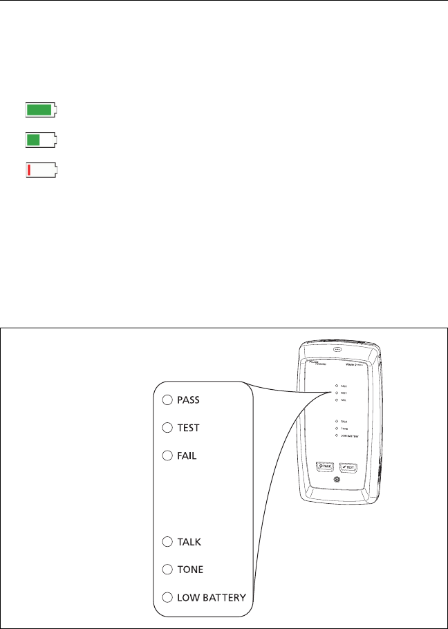
On a remote
The LEDs show the battery status at the end of the power-up
sequence, as shown in Figure 1.
BV102.EPS
Figure 1. LEDs Show the Remote’s Battery Status
84 % - 100 %
67 % - 83 %
51 % - 66 %
34 % - 50 %
18 % - 33 %
0 % - 17 %

Chapter 1: Get Acquainted
Verify Operation
13
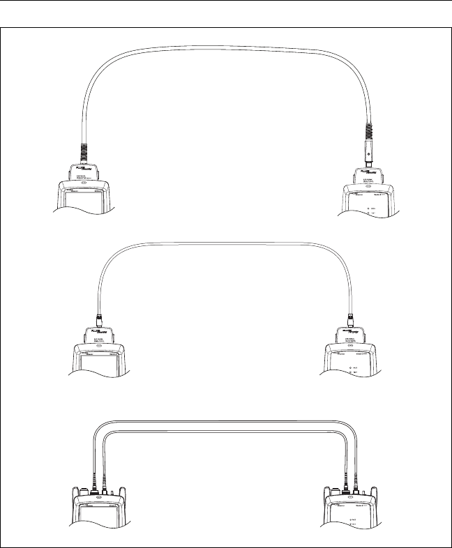
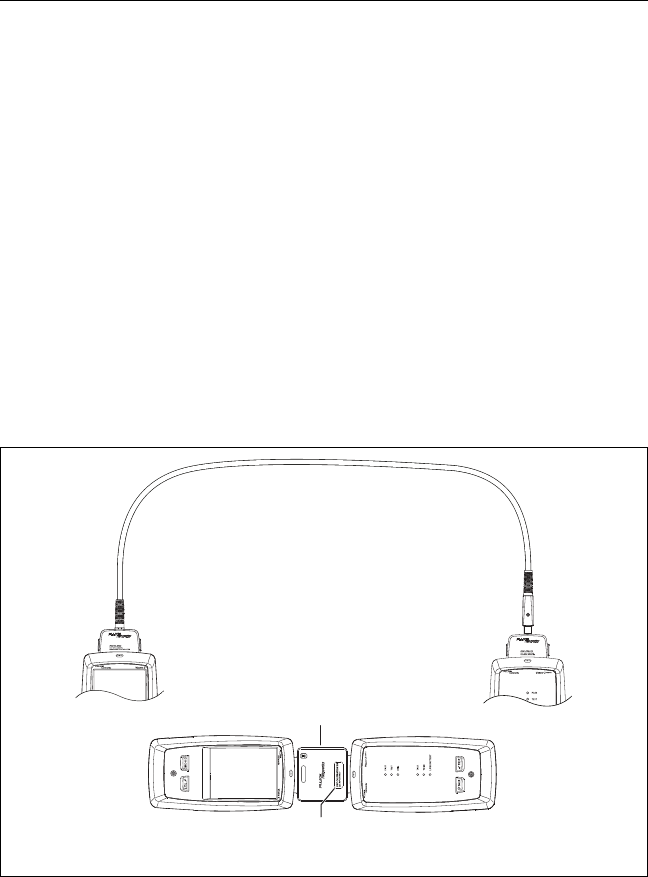
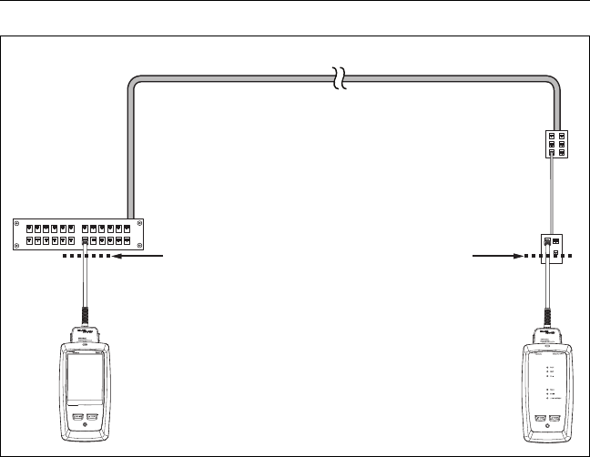
To see more information about a remote’s battery status
1Make the connections shown in Figure 2 and turn on both
testers.
2For CertiFiber Pro testers, select Smart Remote or Loopback
mode.
3Make sure the connection icon shows at the top of the screen
().
4Tap TOOLS, then tap Battery Status.
When the AC adapter is not connected, the screen shows the
Time Remaining, which is the approximate battery life at the
present rate of use.
Verify Operation
The tester does a self test when you turn it on. If the tester shows
an error or does not turn on, refer to “If the Tester Does Not
Operate as Usual” on page 250.
Versiv 2 Cabling Certification Product Family
Users Manual
14
BV148.EPS
Figure 2. Connections to See the Status of a Remote’s Battery
DSX CableAnalyzer modules
with two channel adapters
and a patch cord
CertiFiber Pro
modules and two
fiber patch cords
DSX CableAnalyzer modules
with permanent link and
channel adapters

Chapter 1: Get Acquainted
How to Use the Touchscreen
15
How to Use the Touchscreen
The Versiv 2 main unit’s Taptive™ user interface lets you use a
touchscreen to control the tester. You can operate the
touchscreen with your fingertip or with a stylus that is made for
projected capacitance touchscreens.
WCaution
For correct operation and to prevent damage to the
touchscreen:
Touch the screen only with your fingers or with a
stylus that is made for projected capacitance
touchscreens. Do not use too much force.
Do not touch the screen with sharp objects.
Note
The touchscreen will not respond if you tap it with
your fingernail or an incorrect type of stylus or if
you wear non-conductive gloves.
To use the touchscreen
To select an item on the screen, tap the item lightly with your
fingertip.
To scroll a screen, lightly touch the screen then move your
fingertip in the direction you want the screen to move.
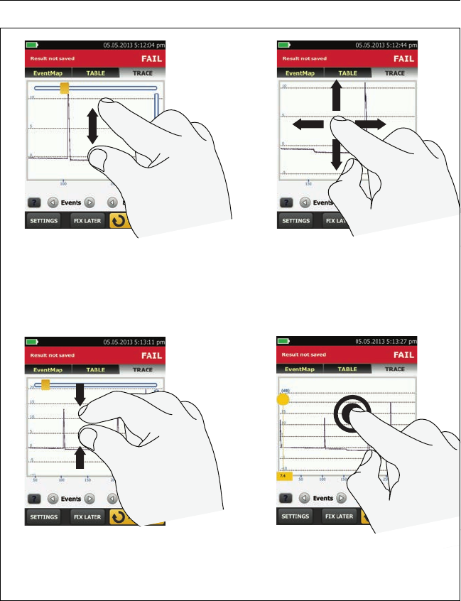
On screens that show a plot, trace, or FiberInspector image,
you can drag some items, such as the measurement cursor on
a plot or trace or the image on a FiberInspector screen. These
screens also have a zoom function, as shown in Figure 3.
To clean the touchscreen
Turn off the tester, then use a soft, lint-free cloth that is moist
with a mild detergent.
WCaution
When you clean the touchscreen, do not let liquid
get under the plastic around the touchscreen.
Versiv 2 Cabling Certification Product Family
Users Manual
16
GPU45.EPS
Figure 3. How to Zoom the Screen
To quickly go back to 1:1
magnification, double-tap the
screen.
To zoom in, use the reverse-
pinch gesture
To zoom out, use the pinch
gesture
To move the image, drag it in
any direction.
Chapter 1: Get Acquainted
Change the Language
17
Change the Language
On the home screen, tap the TOOLS icon, tap Language, then tap
a language.
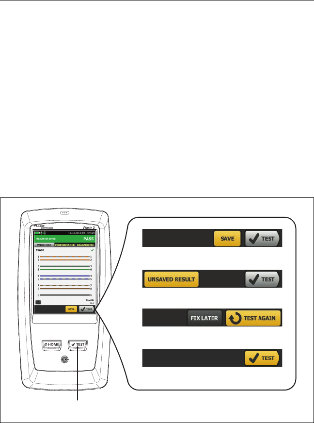
Buttons to Do Tests and Save Results
When a test is completed and more than one button shows at the
bottom of the screen, the tester highlights one in yellow to
recommend which one to tap. Figure 4 shows the buttons you will
see.
Note
To change the Auto Save setting, tap the Next ID
panel on the home screen.
BV40.EPS
Figure 4. FIX LATER, TEST AGAIN, and TEST Buttons and the TEST Key
AB
C
D
F
E
G

Versiv 2 Cabling Certification Product Family
Users Manual
18
SAVE (yellow), TEST (gray): These buttons show if the test
passed and Auto Save is off. When you tap SAVE, you can save
the results with an ID that you make or select. When you tap
TEST, you can select to save the results or do the test again and
not save the results.
UNSAVED RESULT: This button shows if Auto Save is off and
you go to the home screen when a test is completed. Tap this
button to see the result.
FIX LATER: This button shows if the test failed or had a PASS*
result and the result has not been saved.
TEST AGAIN: This button shows if the test failed or had a PASS*
result. Tap this button to do the test again. If Auto Save is on,
the tester saves subsequent results with the same ID. If the test
fails again, you can tap FIX LATER to save the result if necessary.
When you look at a saved result that failed, tap TEST AGAIN to
do the test again for the same ID and with the same test settings
as the saved result.
TEST (yellow): This button shows if the test passed and Auto
Save is on. When Auto Save is on, the tester saves results with
the next available ID when the test is completed. When you tap
TEST, the tester does a test for the next available ID.
: The key does the same function as the TEST button.
When TEST AGAIN shows, you can press to do a test on
the next ID.

Chapter 1: Get Acquainted
Overview of Memory Functions
19
Overview of Memory Functions
These are the approximate numbers of tests you can save in a
Versiv 2 main tester:
DSX CableAnalyzer tests: 12,700 Cat 6A Autotest results, with
plot data included.
CertiFiber Pro tests: Autotest results for 30,000 fibers.
OptiFiber Pro OTDR tests: 2000 OTDR tests on fiber links with
an average length of 2 km, and up to 5000 tests for lengths
less than 2 km.
The number of test results you can save decreases if you save
more tests in each record, or if you save tests that use more
memory. For example, records that include OTDR tests and
images from the video probe use more memory than records
that include OTDR tests and FaultMap tests.
The capacity available for test results depends on the space used
by the software and custom test limits in the tester.
To see the memory status
On the home screen, tap the TOOLS icon, then tap Memory
Status.
To make more memory available, you can export results to a USB
flash drive, then delete the results in the tester. See “Manage
Results on a Flash Drive” on page 218.
Options for Cable IDs
When you save the test results for a cable, you usually give the
results the name that is the ID for the cable. There are several
methods you can use to make IDs for test results:

Versiv 2 Cabling Certification Product Family
Users Manual
20
You can use the CABLE ID SETUP screen to make a set of
sequential IDs. The tester uses the IDs in sequence as the
names for the results you save. When Auto Save is on, the
tester automatically saves each result with the next available
ID in the set.
A cable ID set also lets you use IDs again so you can add
different results to tests you saved before.
You can enter an ID each time you do a test. To do this, turn
off the Auto Save function (see page 20). Each time a test is
completed, tap SAVE (if the test passed) or FIX LATER (if the
test failed), then enter an ID manually.
You can use LinkWare PC software to make a set of IDs,
download the set to the tester, then import it into a project.
After you do a test, you can enter the ID for a test you saved
before. This lets you replace results or add different results to
a test you saved before.
If the test failed before, and you saved the results, you can
select it on the RESULTS screen, then press TEST AGAIN to
replace the results for that ID.
Notes
Cable IDs are case-sensitive. For example, the
tester saves result with the names “A0” and “a0”
in two different records.
A cable ID can have a maximum of 60 characters.
If you delete all the ID sets in a project, the tester
makes a default set that starts with 001.
To turn the Auto Save function on or off
1On the home screen, tap the Next ID panel.
2On the CHANGE ID screen, tap the On/Off control next to
Auto Save.
3Tap DONE.
Chapter 1: Get Acquainted
How to Install a Strap
21
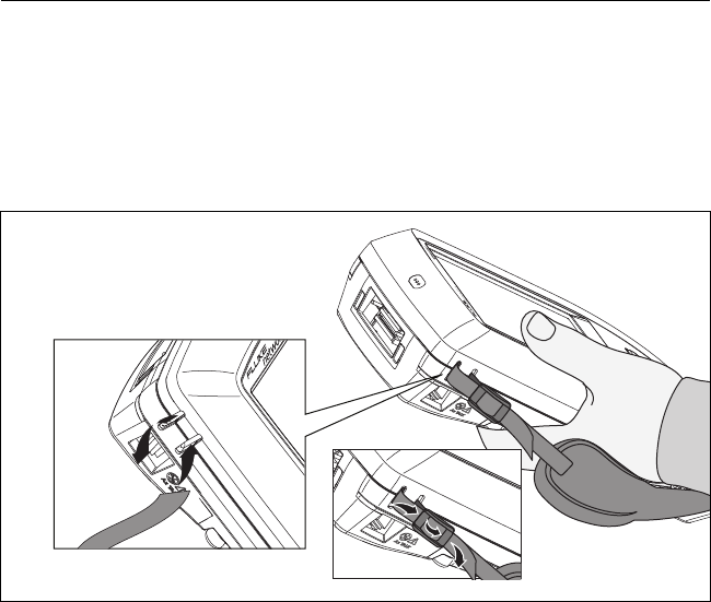
How to Install a Strap
Two types of straps are available for the tester: a hand strap that
helps you hold the tester, and an optional carrying strap that lets
you carry and hang the tester. Figure 5 shows how to install a
strap and how to use the hand strap.
GPU43.EPS
Figure 5. How to Install a Strap and Use the Hand Strap
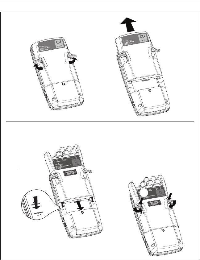
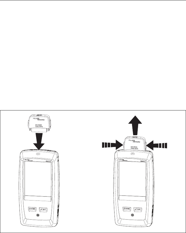
How to Remove or Install a Module
Figure 6 shows how to remove and install the module.
Note
It is not necessary to turn off the tester before you
remove or install a module.
Versiv 2 Cabling Certification Product Family
Users Manual
22
GPU20.EPS
Figure 6. How to Remove and Install a Module
A
B
D
D
C
C
B
A
A
Removal
Installation WCaution
To prevent damage to the case,
push the latches down ()
before you turn them ().

Chapter 1: Get Acquainted
About LinkWare Applications
23
About LinkWare Applications
LinkWare PC Cable Test Management Software
The LinkWare PC Cable Test Management software lets you
upload test records to a PC, organize and examine test results,
print professional-quality test reports, and do software updates
and other maintenance procedures on your tester.
You can download LinkWare PC from the Fluke Networks
website.
The LinkWare Live Web Application
The LinkWare Live web application lets you manage your projects
from a desktop or mobile device.
To get started with LinkWare Live, see Chapter 12.
LinkWare Stats
The LinkWare Stats Statistical Report software that is included
with LinkWare PC software provides statistical analysis of cable
test reports and generates browsable, graphical reports.
For instructions about LinkWare PC and LinkWare Stats software,
see the guides for getting started and the online help available
under Help on the LinkWare PC and LinkWare Stats menus.

Versiv 2 Cabling Certification Product Family
Users Manual
24
25
Chapter 2: Certify Twisted Pair
Cabling
WWarningX
Before you use the DSX CableAnalyzer, read the
safety information that starts on page 5.
Overview of Features
The Fluke Networks DSX CableAnalyzer™ modules attach to
Versiv™ 2 main and remote units to make rugged, hand-held
testers that let you certify, troubleshoot, and document twisted
pair network cabling. The testers includes these features:
DSX-8000 modules certify twisted pair cabling to Cat 8/Class I/
II limits (2000 MHz) in less than 16 seconds.
DSX-5000 modules certify twisted pair cabling to Cat 7A/Class
FA limits (1000 MHz) in less than 15 seconds.
Gives a PASS or FAIL result based on a test limit that you
specify.
You can save approximately 12,700 Cat 6A Autotest results,
with plot data, in the tester’s internal memory. You can save
more results on a removable flash drive.
AxTalk software, which is available on the Fluke Networks
website, lets you do tests for alien crosstalk.
L
DSX-8000
Versiv 2 Cabling Certification Product Family
Users Manual
26
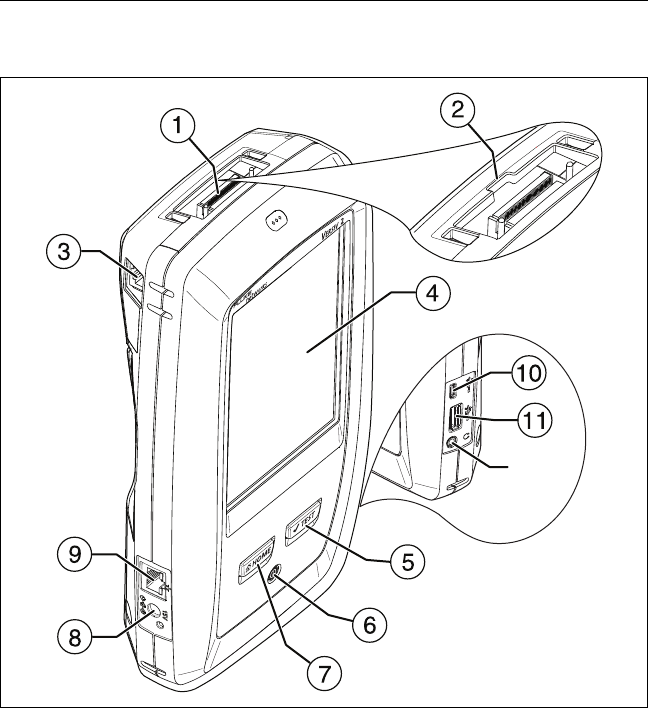
Connectors, Keys, and LEDs
BV88.EPS
Figure 7. Main Tester Connectors, Keys, and LEDs
Connector for a link interface adapter
DSX-8000 modules have a recess for the tabs on Cat 8/Class I
adapters. You cannot attach Cat 8/Class I adapters to
DSX-5000 modules.

Chapter 2: Certify Twisted Pair Cabling
Connectors, Keys, and LEDs
27
RJ45 jack for communications between the main and remote
testers when you do alien crosstalk measurements. See “A
very long cable will fail the Autotest, but you can measure
cable length and compare other results to results from a
known- good cable of the same length to see if the cable is
good.” on page 61.
LCD display with touchscreen
: Starts a test. Turns on the tone generator if a remote
tester is not connected to the main tester. To start a test, you
can also tap TEST on the display.
: Power key
: Press to go to the home screen.
Connector for the AC adapter. The LED is red when the
battery charges, and green when the battery is fully charged.
The LED is yellow if the battery will not charge. See “Charge
the Battery” on page 11.
RJ45 connector: Lets you connect to a network for access to
Fluke Networks cloud services.
Micro-AB USB port: This USB port lets you connect the tester
to a PC so you can upload test results to the PC and install
software updates in the tester.
Type A USB port: This USB host port lets you save test results
on a USB flash drive and connect the FI-1000 video probe to the
tester.
Headset jack
Note
If you have two main testers, you can use one as a
remote. To select the remote function, tap TOOLS
> Main as Remote.
A
C
H
D
I
E
F
G
J
DSX-8000
B
Versiv 2 Cabling Certification Product Family
Users Manual
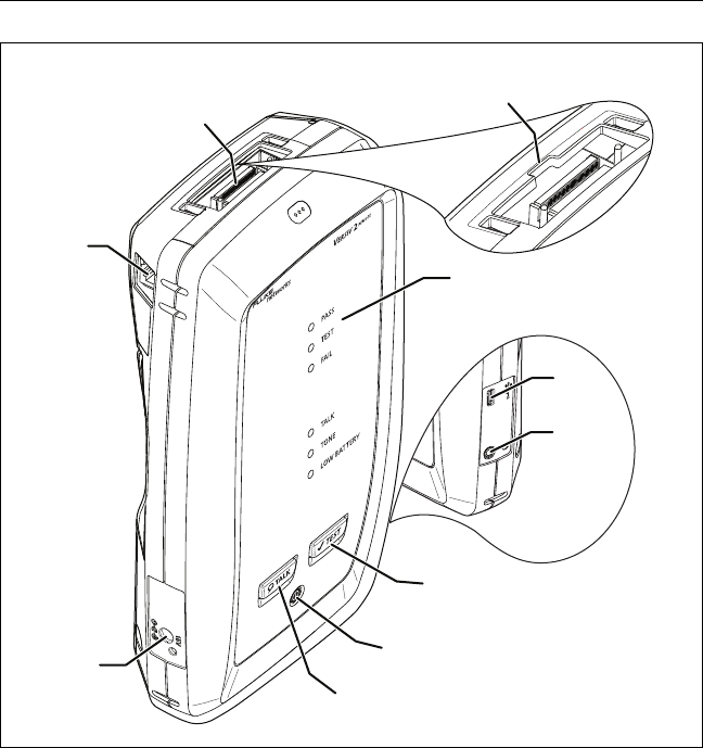
28
BV42.EPS
Figure 8. Remote Tester Connectors, Keys, and LEDs
Connector for a link interface adapter
DSX-8000 modules have a recess for the tabs on Cat 8/Class I
adapters. You cannot attach Cat 8/Class I adapters to
DSX-5000 modules.

Chapter 2: Certify Twisted Pair Cabling
Connectors, Keys, and LEDs
29
RJ45 jack for communications between the main and remote
testers when you do alien crosstalk measurements. See “A
very long cable will fail the Autotest, but you can measure
cable length and compare other results to results from a
known- good cable of the same length to see if the cable is
good.” on page 61.
PASS LED comes on when a test passes.
TEST LED comes on during a test.
FAIL LED comes on when a test fails.
TALK LED comes on when the talk function is on (). The LED
flashes until the main tester accepts the request to talk.
TONE LED flashes and the tone generator comes on if you press
when a main tester is not connected to the remote.
LOW BATTERY LED comes on when the battery is low.
The LEDs also have these functions:
Battery gauge (see Figure 1 on page 12)
Volume indicator for the TALK function
Progress indicator for software updates
: Starts a test. Turns on the tone generator if a main
tester is not connected to the remote.
: Power key
: Press to use the headset to speak to the person at
the other end of the link. Press again to adjust the volume. To
turn off the talk function, hold down .
Connector for the AC adapter. The LED is red when the
battery charges, and green when the battery is fully charged.
The LED is yellow if the battery will not charge. See “Charge
the Battery” on page 11.
Micro-AB USB port: This USB port lets you connect the tester
to a PC so you can install software updates in the tester.
Headset jack
Versiv 2 Cabling Certification Product Family
Users Manual
30
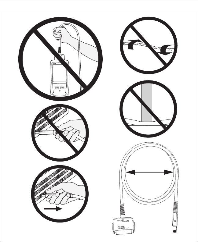
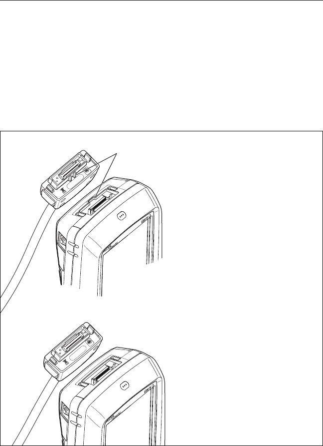
About Link Interface Adapters
Link interface adapters let you connect the DSX CableAnalyzer to
different types of twisted pair links. Figure 9 shows how to attach
and remove adapters.
WCaution
To prevent damage to the cables on the permanent
link adapters and to make sure your test results are
as accurate as possible, do not twist, pull on, pinch,
crush, or make kinks in the cables. See Figure 10 on
page 31.
BV109.EPS
Figure 9. How to Attach and Remove Link Interface Adapters
Chapter 2: Certify Twisted Pair Cabling
About Link Interface Adapters
31
GPU108.EPS
Figure 10. How to Prevent Damage to the Permanent
Link Adapter Cables
5 in (13 cm)
minimum
Versiv 2 Cabling Certification Product Family
Users Manual
32
Adapters for DSX-8000 and DSX-5000
Modules
You can use adapters for test limits up to Cat 7A/Class FA and
coaxial adapters with DSX-8000 and DSX-5000 modules. Be sure
to select a test limit that is appropriate for the adapter.
Cat 8/Class I adapters, such as the DSX-PLA804, have tabs that lets
you attach them only to DSX-8000 modules (see Figure 11).
BV200.EPS
Figure 11. DSX-8000 and DSX-5000 Module and Adapter Differences
DSX-5000 Module
For test limits up to Cat 7A/
Class FA
You cannot attach Cat 8/
Class I adapters to the
module
DSX-8000 Module
For test limits up to Cat 8/
Class I/II
Cat 8/Class I adapters
attach only to DSX-8000
modules
You can attach any other
adapter to the module
Tabs
and recess
Cat 8/Class I
adapter
Cat 7A/Class FA
or below
Chapter 2: Certify Twisted Pair Cabling
The DSX CableAnalyzer Home Screen
33
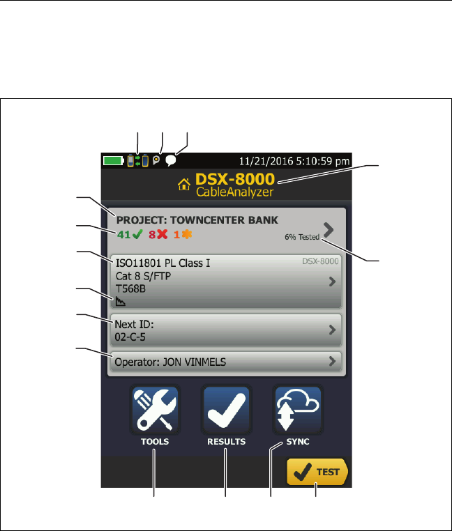
The DSX CableAnalyzer Home Screen
The home screen (Figure 12) shows important test settings. Before
you do a test, make sure these settings are correct.
GPU110.EPS
Figure 12. The Home Screen for the DSX CableAnalyzer
PROJECT: The project contains the settings for a job and helps
you monitor the status of a job. When you save test results, the
tester puts them in the project. Tap the PROJECT panel to edit
the project settings, select a different project, or make a new
project.
A
E
B
F
K
J
C
L
GH
D
MNO
I

Versiv 2 Cabling Certification Product Family
Users Manual
34
Shows a summary of the test results in the project:
: The number of tests that passed.
: The number of tests that failed.
: The number of tests with an overall marginal result.
The test setup panel shows the settings the tester will use
when you tap TEST or press . To change these settings,
tap the panel.
Note
You can set up tests for any module that the
tester can use, even when no module is attached.
Icons show the status of the Store Plot Data and AC Wire Map
settings. See Table 2 on page 40.
Next ID: The Next ID panel shows the ID that the tester gives
to the next test results you save.
Tap Next ID to do these tasks:
Enter an ID, select a different ID in the ID set, select a
different set of IDs, or make a new set. The tester adds the
IDs and ID sets you make to the project that shows on the
home screen.
Turn Auto Save on or off.
Operator: The name of the person who does the job. You can
enter a maximum of 20 operator names. For each operator you
can also enter the email address that the operator will use as an
ID to sign in to LinkWare Live.
TOOLS: The TOOLS menu lets you set the reference, see the
status of the tester, and set user preferences such as the
language and the display brightness.
RESULTS: Tap RESULTS to see and manage the results that are
saved in the tester.
SYNC: Tap SYNC to sync projects with LinkWare Live.
Chapter 2: Certify Twisted Pair Cabling
The DSX CableAnalyzer Home Screen
35
TEST: Tap TEST to do the test shown in the test setup panel.
The percentage of the project that is completed. The
percentage is the number of IDs used for saved results divided
by the total number of used and available IDs in the project.
The number of IDs includes IDs for copper and fiber cable.
% Tested does not show if your project contains only a Next ID
list. See “About Next ID Sets” on page 225 for more information
about the Next ID list.
The type of module attached to the main Versiv 2 unit.
This icon shows when the tester’s link interface adapter
is connected to the adapter on a Versiv 2 remote and the
remote is turned on.
DSX-5000 only: The arrows on the remote connection
icon are orange when the main and remote use long-range
communication mode. See “Long-Range Communication Mode
(DSX-5000)” on page 61.
The asset management icon shows when the owner of a
LinkWare Live account has enabled the asset management
service on the tester. See “About the Asset Management Service”
on page 238.
This icon shows when the talk function is on. To use the
talk function:
1Connect the main and remote testers together through a
link that has one or more good wire pairs.
2Connect headsets to the headset jacks on the testers.
3Press the button on one of the headset microphones or
press on the remote, then speak into the
microphone.

Versiv 2 Cabling Certification Product Family
Users Manual
36
Make Sure Your Tester is Ready to Certify
Cabling
To make sure your tester meets its accuracy specifications, follow
these guidelines:
Keep the tester’s software current. The latest software is
available on the Fluke Networks website. See “Update the
Software” on page 243.
Set the reference for the twisted pair adapters every 30 days.
See page 36.
Make sure that you select the correct cable type for the job, and
that the NVP for the cable is correct. See Table 2 on page 39.
Make sure you select the correct test limit for the job. See
Table 2 on page 39.
Make sure the cords and connectors for all test equipment
and patch cords are in good condition.
Make sure the battery is fully charged.
Send the modules to a Fluke Networks service center every 12
months for factory calibration.
Set the Reference
The reference procedure for twisted pair cable sets the baseline
for insertion loss, ACR-F, and DC resistance measurements.
Set the reference at these times:
When you want to use the tester with a different module. The
tester can save reference values for eight different pairs of
modules.
When you attach Class F/FA link interface adapters, such as the
optional DSX-PLA011 TERA™ adapters.
Every 30 days, at minimum.
To ensure maximum accuracy of test results, set the reference
daily.It is not necessary to set the reference when you change the
Chapter 2: Certify Twisted Pair Cabling
Set the Reference
37
link interface adapters (unless you attach Class F/FA link interface
adapters).
To set the reference
1Install DSX modules in the tester and the remote.
2Turn on the tester and the remote a minimum of 5 minutes
before you set the reference.
Note
Set the reference only after the testers are at an ambient
temperature between 50 °F and 104 °F (10 °C and 40 °C).
3Use the appropriate adapters or a calibration artifact to connect
the main and remote testers together as shown in Figure .On the
home screen, tap TOOLS, then tap Set Reference.
4On the SET REFERENCE screen tap TEST.
BV89.EPS
Figure 13. Reference Connections for Twisted Pair Cable
Permanent link
adapter
Channel
adapter
DSX-8000: DSX-CALIBRATION 2G
DSX-5000: DSX-CALIBRATION
For DSX-8000 modules, use
Cat 8/Class I adapters
Calibration artifact

Versiv 2 Cabling Certification Product Family
Users Manual
38
Settings for Twisted Pair Tests
Table 2 gives descriptions of the settings for twisted pair tests. To
set up a project, which includes the settings in Table 2, cable IDs,
and operator names, see Chapter 11.
To set up a twisted pair test
1On the home screen, tap the test setup panel.
2On the CHANGE TEST screen, select a twisted pair test to
change, then tap EDIT.
Or to set up a new twisted pair test, tap NEW TEST. If no module
is installed, the MODULE screen shows. Tap the correct copper
module.
3On the TEST SETUP screen, tap the panels to change settings
for the test. See Table 2.
4On the TEST SETUP screen, tap SAVE when your test setup is
completed.
5On the CHANGE TEST screen, make sure the button next to
the test is selected, then tap USE SELECTED.

Chapter 2: Certify Twisted Pair Cabling
Settings for Twisted Pair Tests
39
Table 2. Settings for Twisted Pair Tests
Setting Description
Module Select DSX-8000 CableAnalyzer or DSX-5000
CableAnalyzer. See Figure 11 on page 32.
Cable Type Select a cable type that is correct for the type you will
test. To see a different group of cable types, tap MORE,
then tap a group. To make a custom cable type, tap
Custom in the Cable Groups list.
NVPNominal velocity of propagation. The tester uses the NVP
and the propagation delay to calculate the length of the
cable.
The default value is defined by the selected cable type
and is the typical NVP for that cable type. To enter a
different value, tap the NVP panel, then tap or
on the NVP screen to increase or decrease the value.
To find the actual value for a cable, connect a known
length of the cable to the tester, tap MEASURE on the
NVP screen, then change the NVP until the measured
length matches the known length. Use a cable at least
30 m (100 ft) long.
When you increase the NVP value, the calculated length
increases.
Shield Test This setting shows only when you select a shielded cable
type.
On: The wire map test includes a DC test for shield
continuity and AC tests for shield quality. The wire map
test fails if the shield is open or the AC test results are
unsatisfactory.
Off: The wire map shows the shield if the shield has
continuity. The tester does not do AC tests for shield
quality. The wire map test does not fail or show the
shield if the shield is open.
-continued-

Versiv 2 Cabling Certification Product Family
Users Manual
40
Test Limit Select the correct test limit for the job. To see a different
group of limits, tap MORE, then tap the name of a
group.
Store Plot Data Off : The tester does not save plot data for frequency-
domain tests or for the HDTDR/HDTDX analyzers. You
can see the plots before you save the test and exit the
results screen. The saved results show frequency-domain
measurements in a table and do not include the HDTDR/
HDTDX plots.
On : The tester saves plot data for all frequency-
domain tests required by the selected test limit and for
the HDTDR/HDTDX analyzers.
HDTDR/HDTDX Fail/Pass* only: The tester shows HDTDR and HDTDX
analyzer results only for Autotests with PASS*, FAIL*, or
FAIL results.
All Autotests: The tester shows HDTDR and HDTDX
analyzer results for all Autotests.
To get HDTDR/HDTDX analyzer results you can also tap
TOOLS > Diagnostics.
For more information about the HDTDR and HDTDX
analyzers, see the Technical Reference Handbook.
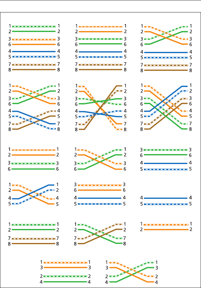
Outlet
Configuration
The Outlet Configuration specifies which wire pairs are
tested and which wire numbers the wire map shows for the
pairs. See Figure 14.
To see the wire map for a configuration, tap Outlet
Configuration, tap the configuration name on the OUTLET
CONFIG screen, then tap SAMPLE.
To select a configuration, tap a name on the OUTLET
CONFIG screen, then tap USE SELECTED.
Note
The OUTLET CONFIG screen shows only the
configurations that are applicable to the
selected Test Limit.
To make a custom outlet configuration, tap CUSTOM on
the OUTLET CONFIG screen, then tap MANAGE, then tap
Create.
Table 2. Settings for Twisted Pair Tests (continued)

Chapter 2: Certify Twisted Pair Cabling
Settings for Twisted Pair Tests
41
AC Wire Map The AC Wire Map test lets you do tests on links connected
through midspan PoE (Power over Ethernet) devices. See
the Technical Reference Handbook.
When the AC Wire Map test is on, this icon shows on the
home screen:
Notes
Always turn off the AC wire map test when you
will not do tests through a PoE device. The AC
wire map test increases the time for an
Autotest. It also disables the resistance and
shield continuity tests.
The DSX-8000 modules do not support the AC
wire map test.
Table 2. Settings for Twisted Pair Tests (continued)
Versiv 2 Cabling Certification Product Family
Users Manual
42
GPU85.EPS
Figure 14. Outlet Configurations
T568A
Rollover
CSU/DSU
ATM/TP-PMD
Straight
ATM/TP-PMD
Crossed
Ethernet
Two-Pair CrossedEthernet Two-Pair Token Ring
T568B
USOC Single-Pair
USOC Two-Pair
Crossover
1000BASE-T Crossover 2 x Two-Pair Crossed
One Pair (1,2)
M12 Two-Pair CrossedM12 Two-Pair
Chapter 2: Certify Twisted Pair Cabling
How to Do an Autotest
43
How to Do an Autotest
When you tap TEST on the main tester or press on the main
or remote tester, the testers do an Autotest. The Autotest
includes all the tests necessary to certify that the cabling meets or
exceeds the performance requirements specified in the selected
test limit.
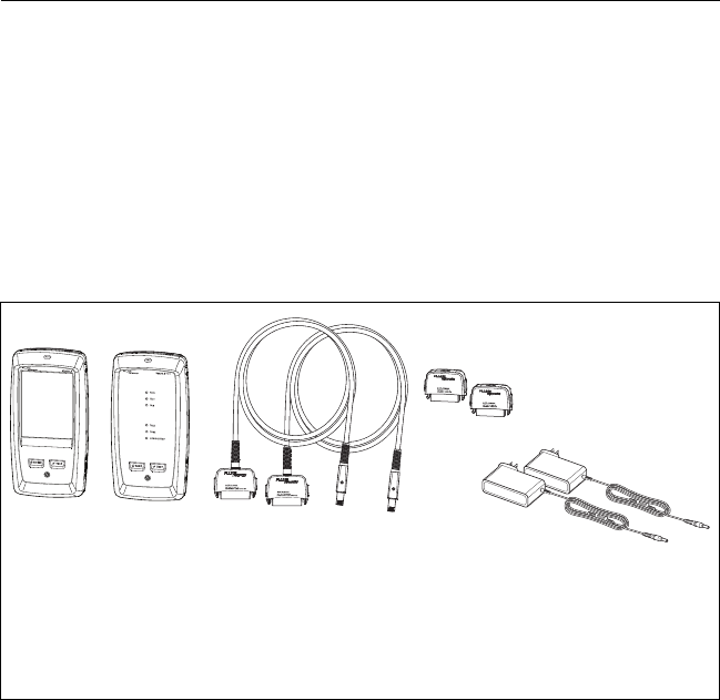
Figure 15 shows the equipment for Autotests on twisted pair
cable.
Figure 15. Equipment for Autotests on Twisted Pair Cable
BV111.EPS
Main and remote Versiv 2 units
with modules installed
For tests on permanent links:
two permanent link adapters
For tests on channels: two
channel adapters
AC adapters (optional)
A
C
BD

Versiv 2 Cabling Certification Product Family
Users Manual
44
To do an Autotest on twisted pair cable
1Attach permanent link or channel adapters to the main and
remote testers.
2Make sure that the home screen shows the correct settings for
the job.
To make sure that other settings are correct, tap the test setup
panel, make sure the correct test is selected on the CHANGE
TEST SCREEN, then tap EDIT to see more settings. Table 2 on
page 39 describes the settings.
3Connect the testers to the link as shown in Figure 16, 17, 18,
or 19.
4Tap TEST on the main tester or press on the main or
remote tester.
If the tester at the other end of the cable is in sleep mode or is
off, your tester’s tone generator turns on the other tester.
If the two testers are not connected:
Your tester’s tone generator stays on. Then, you can use a
tone probe if necessary to find the cable to connect to the
other tester.
Or, tap MEASURE to do the tests that do not require a
remote tester. Because the tester cannot complete all tests
and some tests always fail with no remote connected, the
result for an Autotest without a remote is always FAIL.
Chapter 2: Certify Twisted Pair Cabling
How to Do an Autotest
45
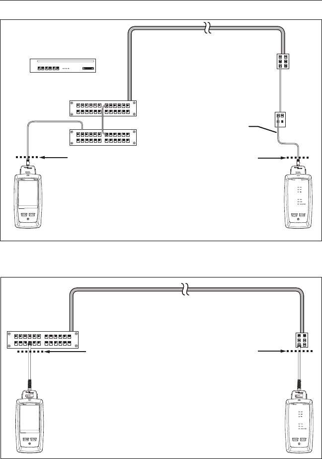
BV97.EPS
Figure 16. Permanent Link Connections for Links Up to Cat 7A
End
permanent
link
Remote with
permanent link
adapter
Optional
consolidation
point
Wall
outlet
Tester with
permanent link
adapter
Start
permanent
link
Patch panel
Horizontal cabling
Versiv 2 Cabling Certification Product Family
Users Manual
46
BV96.EPS
Figure 17. Channel Connections for Links Up to Cat 7A
BV201.EPS
Figure 18. Permanent Link Connections for Cat 8/Class I Links
End
channel
Remote with
channel adapter
Optional
consolidation
point
Wall
outlet
Tester with
channel adapter
Start
channel
Hub or switch
Horizontal cabling
Patch cord
from hub
or switch
Patch cord
from PC
Patch
panels
Horizontal cabling
(24 m maximum)
End
permanent
link
Start
permanent
link
Remote with DSX-8000
module and Cat 8/Class I
permanent link adapter
Tester with DSX-8000
module and Cat 8/
Class I permanent link
adapter
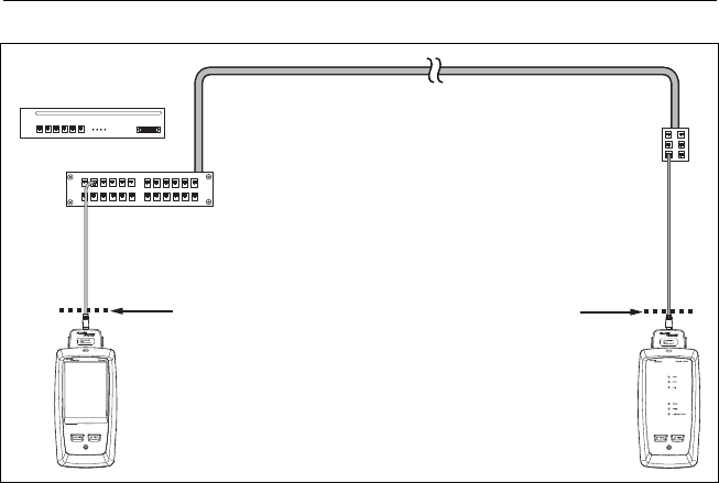
Chapter 2: Certify Twisted Pair Cabling
“Bad Patch Cord” Message
47
BV202.EPS
Figure 19. Channel Connections for Cat 8/Class I Links
“Bad Patch Cord” Message
To comply with standards for tests on channels, the tester
removes the effects of the channel adapters and their
connections from the test results. Before it removes these effects,
the tester makes sure that the plugs on the patch cord do not
have too much near-end crosstalk (NEXT). Too much NEXT is
frequently caused by too much untwisted wire in the plug. If a
plug is bad, the tester shows the message Bad patch cord at main
or Bad patch cord at remote, and does not remove the effects of
the channel adapters and their connections. The tester saves the
message with the results.
If you see one of these messages, replace the patch cord or install
a new plug at the bad end.
Horizontal cabling
(24 m maximum)
End
channel
Start
channel
Remote with DSX-8000
module and Cat 8/Class I
channel adapter
Tester with DSX-8000
module and Cat 8/
Class I channel
adapter
Hub or switch
Patch cord from
hub or switch
Patch cord
from PC

Versiv 2 Cabling Certification Product Family
Users Manual
48
How to Certify Patch Cords
To certify patch cords, you must use the DSX-PCxx Patch Cord
Adapters and the correct patch cord test limit. You cannot use
channel adapters and test limits to certify patch cords because
channel tests do not measure the performance of the patch cord
plugs.
To purchase a DSX-PCxxS Patch Cord Adapter Set, contact an
authorized Fluke Networks distributor.
Twisted Pair Autotest Results
The tests listed below apply to twisted pair cabling.
Note
Some tests are not included in some test limits.
Wire map
Resistance
Resistance unbalance in a pair
Resistance unbalance between pairs
Length
Propagation delay
Delay skew
Insertion loss (attenuation)
Impedance
NEXT (near-end crosstalk)
PS NEXT (power-sum near-end crosstalk)
ACR-N (attenuation to crosstalk ratio at the near end)
PS ACR-N (power-sum attenuation to crosstalk ratio, near
end)
ACR-F (attenuation to crosstalk ratio at the far end)
PS ACR-F (power-sum attenuation to crosstalk ratio, far end)

Chapter 2: Certify Twisted Pair Cabling
Twisted Pair Autotest Results
49
Return loss
TCL (transverse conversion loss)
CDNEXT (common-mode to differential mode near-end
crosstalk)
CMRL (common-mode return loss)
ELTCTL (equal level transverse conversion transfer loss)
HDTDR and HDTDX analyzers (optional tests, not required by
any test limit)
Automatic Diagnostics
If an Autotest on twisted pair cabling fails, the DSX CableAnalyzer
automatically gives you information about faults. To see the
information, tap the FAULT INFO tab. Figure 20 shows examples
of diagnostic information.
To get only diagnostics results, select Diagnostics from the TOOLS
menu. These results do not include a PASS/FAIL status.
The diagnostic screens show connectors in grey when other faults
possibly affect the results for the connector.
For NEXT failures caused by multiple connectors, the diagnostic
screen shows the worst connector in red.
Future Versiv 2 software releases may include additional
diagnostics. The latest software is available at no charge on the
Fluke Networks website.
For more information on diagnostics, including video training
modules, see the Knowledge Base on the Fluke Networks website.
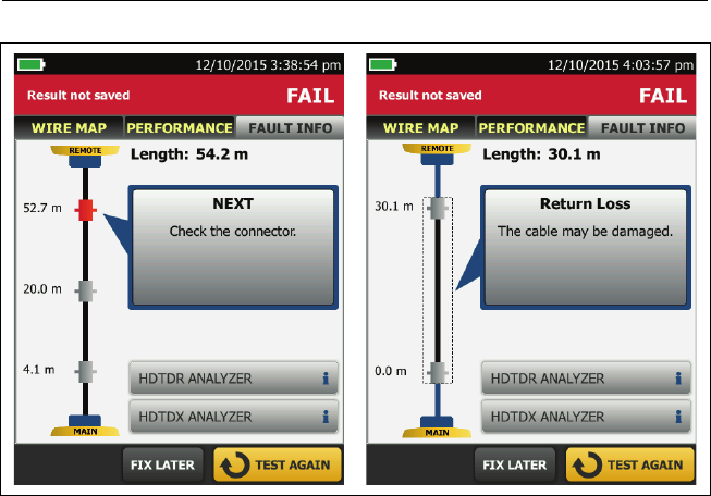
Versiv 2 Cabling Certification Product Family
Users Manual
50
GPU192.EPS
Figure 20. Examples of Fault Information Screens
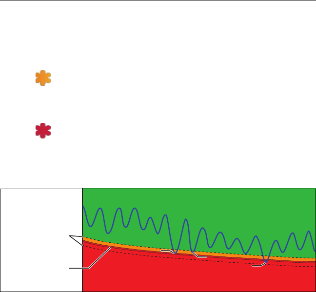
Chapter 2: Certify Twisted Pair Cabling
Twisted Pair Autotest Results
51
PASS*/FAIL* Results
A result shows an asterisk when measurements are in the tester’s
accuracy uncertainty range (Figure 21) and the asterisk is required
by the selected test limit. These results are marginal.
A PASS* shows that the cable’s performance is
satisfactory. If a cable must get a PASS result to agree with
your requirements for quality, identify and correct the
problems with the cable and do the Autotest again.
Usually, a FAIL* is not a satisfactory result. The tester
shows a FAIL for the overall result. Identify and correct the
problems with the cable and do the Autotest again.
GPU87.EPS
Figure 21. PASS* and FAIL* Results
Tester’s accuracy
uncertainty
range
PASS
PASS*
FAIL
Limit FAIL*
PASS*
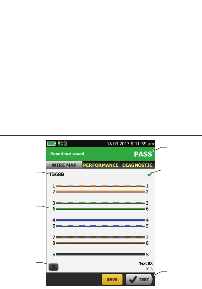
Versiv 2 Cabling Certification Product Family
Users Manual
52
WIRE MAP Tab
The WIRE MAP tab shows the connections between the ends of
the cable under test. The tester compares the connections to the
selected Outlet Configuration to get a PASS or FAIL result.
If the wire map test fails, you can continue or stop the Autotest.
Or, you can tap SCAN ON to do the wire map test continuously
while you look for the fault. To continue the Autotest after you
correct the fault, tap SCAN OFF, then tap CONTINUE.
If you leave then return to the WIRE MAP FAIL screen, the SCAN
ON button goes away. To see the button again, tap TEST AGAIN.
You can also select the continuous wire map test as a single test
from the TOOLS menu. See “Continuous Tests” on page 60.
Figure 22 shows an example of a wire map screen. For
information on AC wire map screens, see the Technical Reference
Handbook.
GPU59.EPS
Figure 22. WIRE MAP Tab
A
D
E
F
B
C
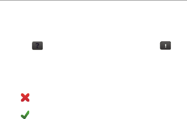
Chapter 2: Certify Twisted Pair Cabling
Twisted Pair Autotest Results
53
The name of the outlet configuration used for the test. The
outlet configuration is a setting on the TEST SETUP screen.
The wire map of the cabling. The main tester is at the left side
of the wire map.
Tap to see information about wire map faults. If
shows, tap it to see a message about the results, such as Bad
patch cord at remote.
The overall result for the Autotest. If the result shows an
asterisk, See “PASS*/FAIL* Results” on page 51.
The result for the wire map test:
The wire map does not agree with the outlet configuration
selected for the test.
The wire map agrees with the outlet configuration selected
for the test.
When more than one button shows at the bottom of the
screen, the tester highlights one in yellow to recommend
which one to tap. See “Buttons to Do Tests and Save Results”
on page 17.
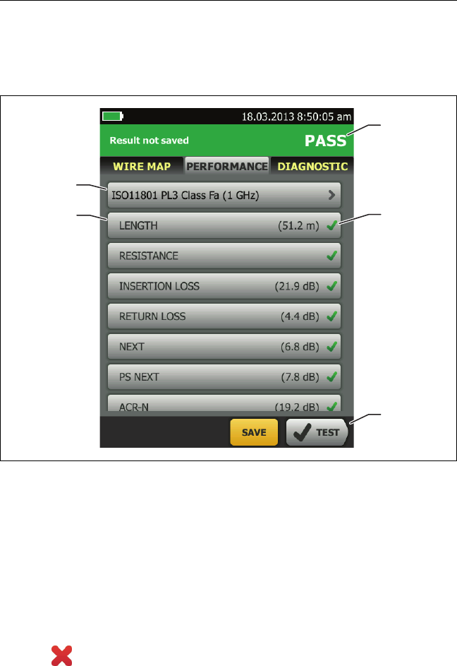
Versiv 2 Cabling Certification Product Family
Users Manual
54
PERFORMANCE Tab
The PERFORMANCE tab (Figure 23) shows the overall result for
each test that is required by the selected test limit.
GPU86.EPS
Figure 23. PERFORMANCE Tab
The test limit and cable type used for the test. To see all the
settings used for the test, tap the panel.
To see detailed results for a test, tap the panel.
The overall result for the Autotest. If the result shows an
asterisk, See “PASS*/FAIL* Results” on page 51.
The overall result for the test:
The results exceed the limit.
B
C
D
E
A

Chapter 2: Certify Twisted Pair Cabling
Twisted Pair Autotest Results
55
The results are within the limit.
The selected test limit does not have a limit for the test, or
a dB rule applies. See the Technical Reference Handbook.
The results are within the range of accuracy uncertainty
for the tester. See “PASS*/FAIL* Results” on page 51.
The measurement shown for frequency-domain results is the
worst margin. (The insertion loss plot is different. See the
Technical Reference Handbook.)
When more than one button shows at the bottom of the
screen, the tester highlights one in yellow to recommend
which one to tap. See “Buttons to Do Tests and Save Results”
on page 17.
Frequency-Domain Results
Frequency-domain results are the measurements that change
with frequency, such as insertion loss and crosstalk.
How to Save Frequency-Domain Results as a Plot or a Table
If Store Plot Data is on when you do a test, the saved results show
as plots. If Store Plot Data is Off, the tester does not save plot data
for frequency-domain tests or for the HDTDR/HDTDX analyzers.
You can see the plots before you save the test and exit the results
screen. Figures 24 and 25 show examples of the two types of
screens. Also see “Store Plot Data” on page 40.
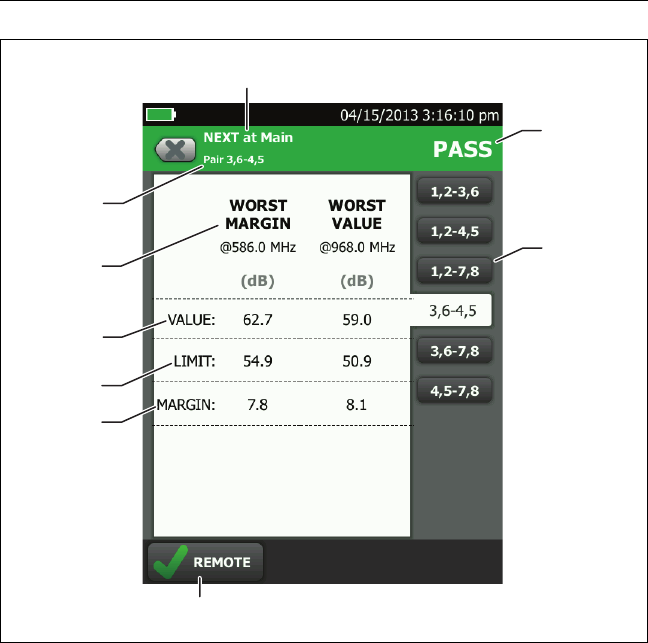
Versiv 2 Cabling Certification Product Family
Users Manual
56
GPU104.EPS
Figure 24. Tabular Results Screen for a Frequency-Domain Test
The location where the tester made the measurements. To
switch between results for the main and remote, tap REMOTE
or MAIN ().
The results are for the wire pair or pairs shown. To see the
results for a different pair or pairs, tap a tab on the right side
of the screen ().
WORST MARGIN is the measurement that is nearest to the
limit line or exceeds the limit by the largest amount. WORST
VALUE is the worst measurement.
D
B
H
G
I
C
E
F
A

Chapter 2: Certify Twisted Pair Cabling
Twisted Pair Autotest Results
57
The measured value.
The limit specified by the selected test limit.
MARGIN is the difference between the measured value and
the limit. The value is in a red box if the measurement exceeds
the limit.
To switch between results for the main unit and the remote,
tap REMOTE or MAIN.
To see the results for a different pair or pairs, tap a tab.
The result for the pair. If the result shows an asterisk, see
“PASS*/FAIL* Results” on page 51.
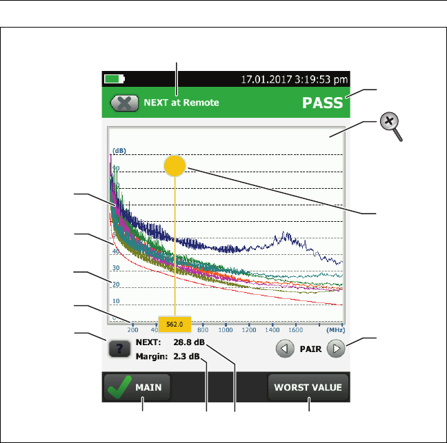
Versiv 2 Cabling Certification Product Family
Users Manual
58
GPU71.EPS
Figure 25. Plot Screen for a Frequency-Domain Test
The location of the measurements. To switch between results
for the main and remote, tap REMOTE or MAIN ().
Measured values for the wire pairs.
The limit line (in red) for the measurement.
Note
If the limit line is black, the tester does not
evaluate the measurement at those frequencies
because a dB rule applies. See the Technical
Reference Handbook.
E
F
J
G
K
M
A
B
C
D
H I
L
Chapter 2: Certify Twisted Pair Cabling
Twisted Pair Autotest Results
59
The vertical scale is the measured value in decibels.
The horizontal scale is the frequency range in megahertz.
To see help for the screen, tap .
To switch between results for the main unit and the remote,
tap REMOTE or MAIN.
The margin at the cursor’s location. The margin is the
difference between the measured value and the limit. The
margin is negative if the pair failed.
The measured value at the cursor’s location.
When you first look at the plot, the cursor is at the frequency
of the worst margin. To move the cursor to the worst value,
tap WORST VALUE. (The insertion loss plot is different. See
the Technical Reference Handbook.)
To see the plots for pairs, tap or . To select pairs to
show on the plot, touch or for one second to see the
SELECT PAIRS window. Select the pairs you want to see, then
tap OK.
When you first look at the plot, the cursor is at the frequency
of the worst margin. To move the cursor to the worst value,
tap WORST VALUE (). The box at the bottom of the cursor
shows the frequency at the cursor’s position.
To move the cursor to other points, touch and drag the yellow
circle at the top of the cursor.
To move the cursor in small increments, tap the yellow circle,
then tap the arrow buttons that show on the plot ( or ).
The overall result for the test. If you look at pairs, the result is
for those pairs. If the result shows an asterisk, see “PASS*/
FAIL* Results” on page 51.
To zoom in and out, use the pinch, reverse-pinch, and double-
tap gestures on the touchscreen. You can also use the zoom
controls to change the magnification on the frequency and
decibels scales independently. See Figure 3 on page 16.
Versiv 2 Cabling Certification Product Family
Users Manual
60
DIAGNOSTIC and FAULT INFO Tabs
If the Autotest failed or had a marginal result, the FAULT INFO
tab shows. If the test passed and you selected All Autotests for
the HDTDR/HDTDX setting on the TEST SETUP screen, the
DIAGNOSTIC tab shows. These tabs give you access to the HDTDR
and HDTDX analyzer plots. The plots help you locate the causes of
NEXT and return loss failures. See the Technical Reference
Handbook.
Continuous Tests
To do the wire map, length, or resistance test continuously, go to
the home screen, tap TOOLS > Single Tests, then tap a test.
The wire map test compares the results to the outlet
configuration specified by the selected test limit and shows if
the connections agree or if they do not.
The length and resistance tests do not compare the results to a
test limit.
To save the result, tap SCAN OFF > SAVE. The saved test has an
for the overall result.

Chapter 2: Certify Twisted Pair Cabling
Long-Range Communication Mode (DSX-5000)
61
Long-Range Communication Mode (DSX-5000)
DSX-5000 modules have a long-range communication mode that lets
you do tests on very long cables, such as spools of cable and long
links used for voice communications. The DSX-5000 automatically
uses this mode when the cable is too long for normal
communications between the main and remote testers. For example,
a Cat 6 cable longer than approximately 200 m will cause the testers
to use long-range communication mode.
When the testers use long-range communication mode, the arrows
on the connection icon are orange:
Note
Tests take more time to complete in long-range
communication mode. For example, an Autotest
can take 90 seconds to two minutes to complete.
A very long cable will fail the Autotest, but you can measure cable
length and compare other results to results from a known- good
cable of the same length to see if the cable is good.
About the AxTalk Analyzer Kit
The DSX CableAnalyzer kit includes the hardware and AxTalk
Analyzer software you need to do tests for alien crosstalk on
twisted pair cabling. Alien crosstalk is noise, or crosstalk,
transmitted between adjacent cables in a bundle or patch panel.
Alien crosstalk is a primary source of noise in cabling used for
10GBASE-T applications and above.
For instructions on how to do alien crosstalk tests, install the
AxTalk Analyzer software, which is available on the Fluke
Networks website, then see the online help in the software.

Versiv 2 Cabling Certification Product Family
Users Manual
62
63
Chapter 3: Certify Coaxial Cabling
The optional DSX-CHA003 coaxial adapters let you use the DSX
CableAnalyzer to certify coaxial cabling for network and video
applications.
Set the Reference for Coaxial Tests
To use DSX-CHA003 adapters, you must set the reference for
coaxial tests. The reference procedure sets a baseline for insertion
loss and resistance measurements.
Set the reference at these times:
When you want to use the tester with a different module. The
tester can save reference values for eight different pairs of
modules.
Every 30 days, at minimum.
To ensure maximum accuracy of test results, set the reference
daily.
Note
It is not necessary to set the reference again if you
use different coaxial adapters.
To set the reference
1Make the connections shown in Figure 26.
2Turn on the tester and the remote a minimum of 5 minutes
before you set the reference.
-continued-
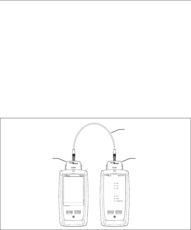
Versiv 2 Cabling Certification Product Family
Users Manual
64
Notes
Set the reference only after the testers are at an
ambient temperature between 10 °C and 40 °C
(50 °F and 104 °F).
The tester will not let you set the reference if the
patch cord is longer than 30 cm (12 in).
You can also set the reference with a 50 patch
cord
3On the home screen, select a coaxial cable test.
4On the home screen, tap TOOLS, then tap Set Reference.
5On the SET REFERENCE screen tap TEST.
Figure 26.
BV179.EPS
Reference Connections for Tests on Coaxial Cabling
DSX-CHA003
COAX ADAPTER
DSX-CHA003
COAX ADAPTER
Coaxial adapter
with F connector
adapter
30 cm (12 in) 75
coaxial patch cord
Coaxial adapter
with F connector
adapter

Chapter 3: Certify Coaxial Cabling
Settings for Coaxial Tests
65
Settings for Coaxial Tests
Table 3 gives descriptions of the settings for coaxial tests. To set
up a project, which includes the settings in Table 3, cable IDs, and
operator names, see Chapter 11.
To set up a coaxial test
1On the home screen, tap the test setup panel.
2On the CHANGE TEST screen, select a coaxial test to change,
then tap EDIT.
Or to set up a new coaxial test, tap NEW TEST. If no module is
installed, the MODULE screen shows. Tap DSX-8000
CableAnalyzer or DSX-5000 CableAnalyzer.
3On the TEST SETUP screen, tap the panels to change settings
for the test. See Table 3.
4On the TEST SETUP screen, tap SAVE when your test setup is
completed.
5On the CHANGE TEST screen, make sure the button next to
the test is selected, then tap USE SELECTED.
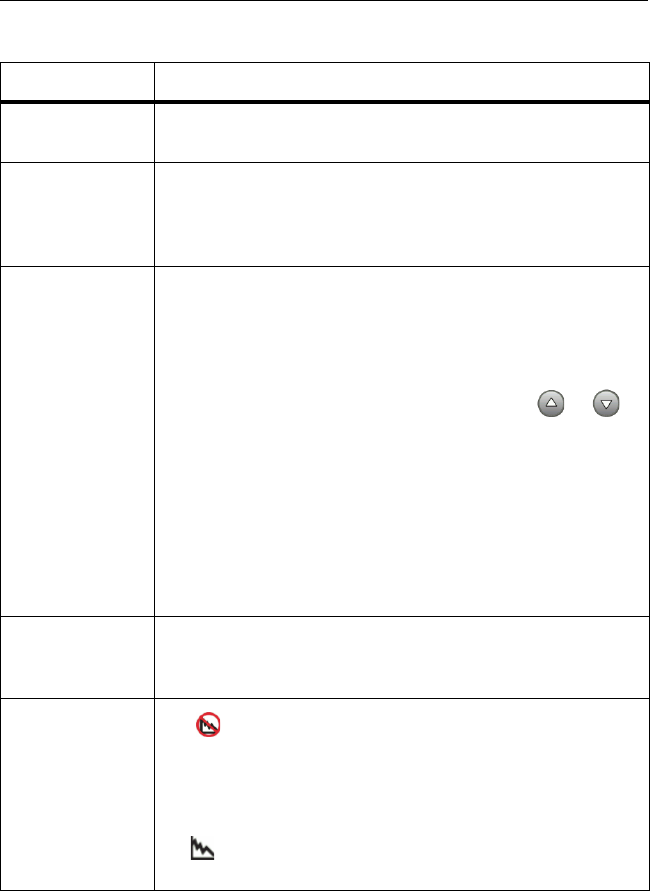
Versiv 2 Cabling Certification Product Family
Users Manual
66
Table 3. Settings for Coaxial Tests
Setting Description
Module Select DSX-8000 CableAnalyzer or DSX-5000
CableAnalyzer.
Cable Type Select a cable type that is correct for the type you will
test. To see a different group of cable types, tap MORE,
then tap a group. To make a custom cable type, tap
Custom in the Cable Groups list.
NVPNominal velocity of propagation. The tester uses the NVP
and the propagation delay to calculate the length of the
cable.
The default value is defined by the selected cable type
and is the typical NVP for that cable type. To enter a
different value, tap the NVP panel, then tap or
on the NVP screen to increase or decrease the value.
To find the actual value for a cable, connect a known
length of the cable to the tester, tap MEASURE on the
NVP screen, then change the NVP until the measured
length matches the known length. Use a cable at least
30 m (100 ft) long.
When you increase the NVP value, the calculated length
increases.
Test Limit Select the correct test limit for the job. To see a different
group of limits, tap MORE, then tap the name of a
group.
Store Plot Data Off : The tester does not save plot data for insertion
loss or for the HDTDR analyzer. You can see the plots
before you save the test and exit the results screen. The
saved results show insertion loss measurements in a table
and do not include the HDTDR plot.
On : The tester saves plot data for the insertion loss
test and for the HDTDR analyzer.
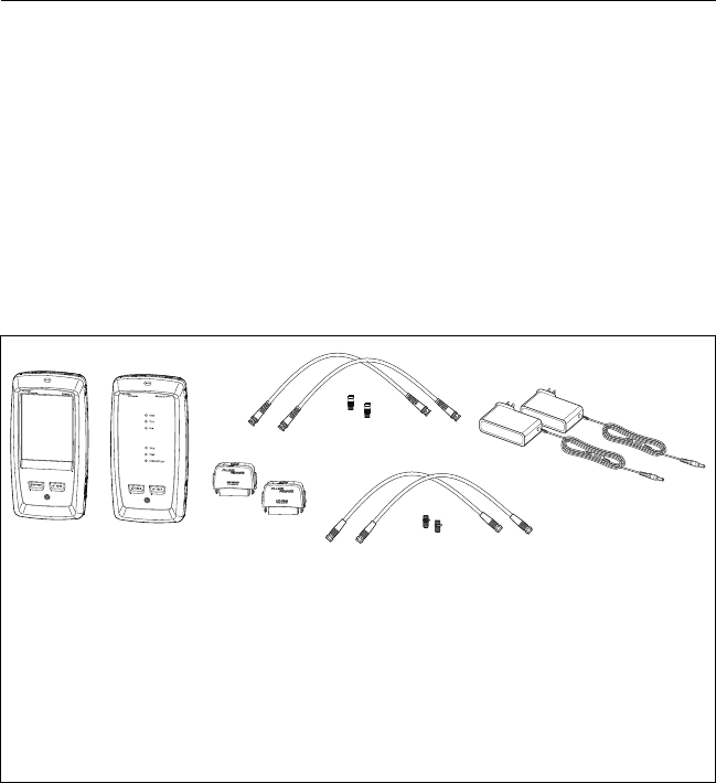
Chapter 3: Certify Coaxial Cabling
How to Do an Autotest
67
How to Do an Autotest
Figure 27 shows the equipment for tests on coaxial cabling.
Notes
You can do the HDTDR, length, and resistance
tests without a remote tester. See “Tests Without
a Remote” on page 72.
If you have two main testers, you can use one as a
remote. To select the remote function, tap TOOLS
> Main as Remote.
Figure 27. Equipment for Tests on Coaxial Cabling
BV181.EPS
Main and remote Versiv 2 units
with modules installed
Two DSX-CHA003 adapters
For tests on network cabling:
F-connector to BNC adapters
and patch cords (typically 50 )
For tests on video cabling:
F-connector adapters and patch
cords (typically 75 )
AC adapters (optional)
A
C
BD
E

Versiv 2 Cabling Certification Product Family
Users Manual
68
To do an Autotest
1Attach coaxial adapters to the main and remote testers.
2Make sure that the home screen shows the correct settings for
the job.
To make sure that other settings are correct, tap the test setup
panel, make sure the correct test is selected on the CHANGE
TEST screen, then tap EDIT to see more settings. Table 3 on
page 66 describes the settings.
3Connect the testers to the link as shown in Figure 28.
WCaution
To make sure your results are reliable:
Disconnect all taps and devices from the cable.
Do not do tests through splitters (See “About
Splitters” on page 71).
4Tap TEST on the main tester or press on the main or
remote tester.
If the tester at the other end of the cable is in sleep mode or is
off, your tester’s tone generator turns on the other tester.
If the two testers are not connected:
Your tester’s tone generator stays on so you can use a
tone probe to find the cable to connect to the other
tester.
Or, tap MEASURE to do the length and resistance tests,
which do not require a remote tester. Because the tester
cannot complete all tests, and the reflection at the end of
the cable exceeds the 15% limit for the HDTDR test, the
result for an Autotest without a remote is always FAIL.
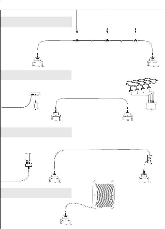
Chapter 3: Certify Coaxial Cabling
How to Do an Autotest
69
BV184.EPS
Figure 28. Examples of Connections for Tests on Coaxial Cabling
DSX-CHA003
COAX ADAPTER
DSX-CHA003
COAX ADAPTER
DSX-CHA003
COAX ADAPTER
DSX-CHA003
COAX ADAPTER
DSX-CHA003
COAX ADAPTER
DSX-CHA003
COAX ADAPTER
DSX-CHA003
COAX ADAPTER
Disconnect all drop cables
MoCA
adapter
MoCA
adapter
Router
IP cameras
Data network
Surveillance network
Cable TV
Cable spools
Coaxial segment
Note: Do not do tests
through splitters.
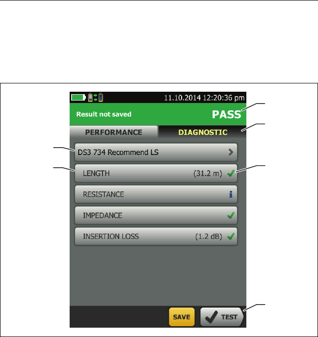
Versiv 2 Cabling Certification Product Family
Users Manual
70
Coaxial Autotest Results
Note
Not all test limits include all the tests shown in
Figure 29.
GPU182.EPS
Figure 29. Autotest Results for Coaxial Cabling
The test limit and cable type used for the test.
To see detailed results for a test, tap the panel.
The overall result for the Autotest. If the result shows an asterisk,
See “PASS*/FAIL* Results” on page 51.
A
C
E
F
B
D

Chapter 3: Certify Coaxial Cabling
About Splitters
71
The DIAGNOSTIC tab shows the HDTDR analyzer button, which
you can tap to see the HDTDR plot. The plot helps you find faults
on the cable. The HDTDR plot for coaxial cable includes limit lines
and a PASS/FAIL result.
The overall result for the test:
The results exceed the limit.
The results are within the limit.
The selected test limit does not have a limit for the test.
The results are within the range of accuracy uncertainty
for the tester. See “PASS*/FAIL* Results” on page 51.
The measurement shown for the insertion loss plot is the worst
value if the test passed, or the worst margin if the test failed.
When more than one button shows at the bottom of the screen,
the tester highlights one in yellow to recommend which one to
tap. See “Buttons to Do Tests and Save Results” on page 17.
To do the resistance test continuously, select the test from the
TOOLS menu. This function helps you locate intermittent faults.
About Splitters
If you get these results, there might be a splitter on the cable:
The tester cannot find the remote.
The tester looses communication with the remote. The test
might continue, then loose communication again as the
splitter interferes with the communication signal.
The length test shows End not found.
The resistance test shows an open.
The HDTDR plot shows a reflection that has an unusual shape.
Because splitters can cause unreliable test results, you should not
do tests through them.

Versiv 2 Cabling Certification Product Family
Users Manual
72
Tests Without a Remote
You can do the length, resistance, and HDTDR tests without a
remote tester. Table 4 describes the effects of a remote on tests.
1Attach a coaxial adapter to the main tester.
2Make sure that the home screen shows the correct settings for
the job.
To make sure that other settings are correct, tap the test setup
panel, make sure the correct test is selected on the CHANGE
TEST screen, then tap EDIT to see more settings. Table 3 on
page 66 describes the settings.
3Connect the tester as shown in Figure 30.
4To do an Autotest: Tap TEST on the main tester or press
on the main or remote tester. When the MEASURE button
shows, tap it to do the length and resistance tests, which do
not require a remote tester.
To do only the length or resistance test: On the home screen
tap TOOLS > Single Tests, then tap a test.
To do only the HDTDR test: On the home screen tap TOOLS >
Diagnostics, then tap HDTDR.
Note
Because the tester cannot complete all tests, and
the reflection at the end of the cable exceeds the
15% limit for the HDTDR test, the result for an
Autotest without a remote is always FAIL.

Chapter 3: Certify Coaxial Cabling
Tests Without a Remote
73
Figure 30. Connections for Coaxial Tests Without a Remote
Table 4. Remote Requirements for Coaxial Tests
Test Remote Requirements*
HDTDR
analyzer
Optional. Without a remote, the plot shows large
reflections at the end of the cabling.
Resistance A remote or a terminator is required for a loop resistance
measurement.
Length Not required.
Because a coaxial cable terminator eliminates signal
reflections, the tester cannot measure the length of
terminated cabling. The tester shows End not found in this
case.
Impedance Optional.
Without a remote or terminator, the tester cannot measure
the impedance of cables longer than 984 ft (300 m). The
tester shows Unknown in this case.
Propagation
delay
Not required.
Because a coaxial cable terminator eliminates signal
reflections, the tester cannot measure the propagation
delay of terminated cabling. In this case, the tester shows
End not found.
Insertion Loss Required.
* If a remote is not required for a test, the test runs without activating the toner
when no remote is detected.

Versiv 2 Cabling Certification Product Family
Users Manual
74
Continuous Tests
To do the length or resistance test continuously, go to the home
screen, tap TOOLS > Single Tests, then tap a test.
The length and resistance tests do not compare the results to a
test limit.
To save the result, tap SCAN OFF > SAVE. The saved test has an
for the overall result.
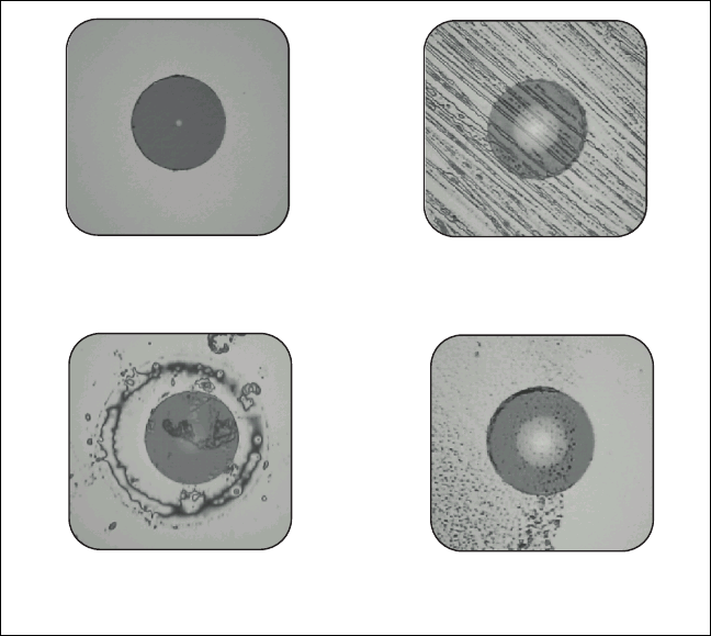
75
Chapter 4: Clean Fiber Endfaces
Always Clean Endfaces Before Tests
When a fiber optic link does not operate correctly, the cause is
frequently a dirty endface in a connector. Figure 31 shows
examples of dirty endfaces and an endface that has been correctly
cleaned and polished.
GPU36.EPS
Figure 31. Examples of Clean and Dirty Fiber Endfaces
Cleaned and polished correctly Wiped on a shirt
Dirty connector on
a patch cord
Contamination that remains
after alcohol dries

Versiv 2 Cabling Certification Product Family
Users Manual
76
Always clean and inspect the endfaces in fiber connectors before
you make connections. Fluke Networks recommends that you use
a mechanical device, such as the Fluke Networks Quick Clean™
Cleaner, to clean connectors on network equipment. If you do not
have such a device, if the device does not clean the connector
sufficiently, or when you clean connectors on test reference cords,
use other optical-grade supplies such as wipes and solvent.
Figure 32 shows the equipment you use to clean and inspect fiber
endfaces.
WWarning*
To prevent possible eye damage caused by
hazardous radiation:
Do not look directly into optical connectors. Some
optical equipment emits invisible radiation that can
cause permanent damage your eyes.
Before you clean an endface, turn off any optical
sources (laser or LED) that are connected to the
fiber.
When you inspect endfaces, use only magnification
devices that have the correct filters.
WCaution
To prevent damage to connectors and to keep
contamination off of endfaces:
Always cover unused connectors and adapters with
protective caps.
Always keep unused protective caps in a clean,
sealed container to prevent contamination.
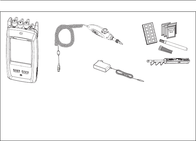
Chapter 4: Clean Fiber Endfaces
Always Clean Endfaces Before Tests
77
Figure 32. Equipment to Clean and Inspect Fiber Endfaces
BV49.EPS
Versiv 2 main unit with
CertiFiber Pro, OptiFiber Pro, or
blank module installed
FI-1000 video probe with USB
connector
Fiber cleaning supplies
AC adapter (optional)
AD
C
B

Versiv 2 Cabling Certification Product Family
Users Manual
78
How to Use a Fluke Networks Quick Clean
Cleaner
WCaution
To prevent damage to the device and to connectors
and to keep contamination off of endfaces, read all
instructions and obey all safety precautions given in
the instructions for the device you use to clean
connectors.
To clean the connectors on test reference cords, use
wipes and solvent. The Quick Clean cleaner cleans
the fiber core, but can leave contamination around
the core. The contamination can move to the core
when you make connections. See “To Clean
Connector Ends” on page 81.
1Use the video probe to inspect the connector. If it is dirty,
continue to step 2.
2To clean a bulkhead connector, remove the cap. To clean the
connector on a fiber cable, remove only the tip of the cap.
3If necessary for a bulkhead connector, extend the tip of the
device.
4Push the device straight into the connector until you hear a
loud click. See Figure 33. Then remove the device.
5Use the video probe to inspect the connector. If necessary,
clean and inspect the connector again.
If the mechanical device does not clean the connector
sufficiently, use a swab and solvent to clean the connector.
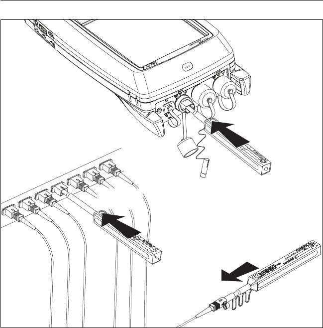
Chapter 4: Clean Fiber Endfaces
How to Use a Fluke Networks Quick Clean Cleaner
79
BV16.EPS
Figure 33. How to Use the One Click Cleaner
CLICK!
CLICK!
CLICK!

Versiv 2 Cabling Certification Product Family
Users Manual
80
How to Use Wipes, Swabs, and Solvent
WCaution
To prevent damage to connectors and to keep
contamination off of endfaces:
Always discard wipes or swabs after you use them.
Do not let solvent dry on an endface. Some solvents
leave a residue after they dry.
If you must use alcohol as a solvent, make sure you
use 99%-pure, anhydrous alcohol.
Put wipes on a soft surface, such as a stack of wipes,
that will conform to the shape of the fiber endface.
When you rub fiber endfaces against a dry cleaning
pad, always use short strokes (~1 cm or ~0.4 in).
Long strokes against a dry pad can cause a build-up
of static charge that can attract dust to the endface.
To Clean Bulkhead Connectors
1Use a video probe to inspect the connector. If it is dirty,
continue to step 2.
2Touch the tip of a fiber optic solvent pen or swab soaked in
solvent to a lint-free dry wipe or fiber cleaning card.
3Touch a new, dry swab to the solvent spot on the wipe or
card. Push the swab into the connector, twist it around 3 to 5
times against the end-face, then remove and dispose of the
swab.
4Dry the connector with a dry swab by twisting it around in the
connector 3 to 5 times.
5Use a video probe to inspect the connector. If necessary, clean
and inspect the connector again.

Chapter 4: Clean Fiber Endfaces
How to Use Wipes, Swabs, and Solvent
81
To Clean the Optical Connectors on the Modules
To clean the optical connectors on the modules, first use the
procedure given under “To Clean Bulkhead Connectors”.
If a connector is very dirty or the procedure above does not make
it clean, use this procedure:
1Unscrew the adapter on the connector.
2Clean the ferrule or photodiode lens with a dry, optical-grade
wipe made for fiber optic connectors.
3Use a video probe to inspect the connector. If necessary, clean
and inspect the connector again.
4If the connector stays dirty, use a wipe that is moist with
optical-grade solvent to clean the endface. Dry the ferrule or
lens with a dry wipe.
To Clean Fiber Adapters
At regular intervals, clean fiber adapters with a swab and fiber
optic solvent. Dry with a dry swab.
To Clean Connector Ends
1Use a video probe to inspect the connector. If it is dirty,
continue to step 2.
2Touch the tip of a fiber optic solvent pen or swab soaked in
solvent to a lint-free dry wipe or fiber cleaning card.
3Rub the connector end-face across the solvent spot, then back
and forth once across the dry area of the wipe or card.
Typically, one or two short strokes (~1 cm or ~0.4 in) are
sufficient to dry the endface.
4Use a video probe to inspect the connector. If necessary, clean
and inspect the connector again.

Versiv 2 Cabling Certification Product Family
Users Manual
82
Notes
For APC connectors, hold ferrule against the
cleaning area at the same angle (typically 8°) as
the ferrule endface.
For some connector types, such as VF-45, it is
necessary to use a different method to clean the
endface.
83
Chapter 5: Inspect Fiber Endfaces
The optional FI-1000 FiberInspector™ video probe connects to the
type A USB port on the Versiv 2 main unit to let you inspect the
endfaces in fiber optic connectors. The probe lets you see dirt,
scratches, and other defects that can cause unsatisfactory
performance or failures in fiber optic networks.
The FI-1000 probe is included with the FI-7000 kit. The probe is an
optional accessory for the CertiFiber Pro and OptiFiber Pro testers.
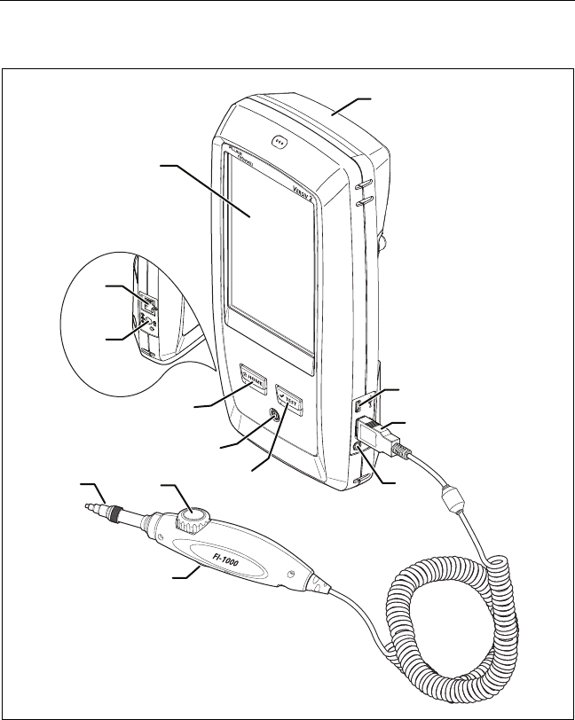
C
E
G
H
F
J
I
A
B
D
L
K
M
Versiv 2 Cabling Certification Product Family
Users Manual
84
Connectors, Keys, and LEDs
BV173.EPS
Figure 34. Connectors, Keys, and LEDs
LCD display with touchscreen.
Blank module included with the FI-7000 kit. Keep the module
installed to give protection to the module connectors.

Chapter 5: Inspect Fiber Endfaces
Connectors, Keys, and LEDs
85
You can use the FiberInspector function with any module
installed and with no module installed.
Micro-AB USB port: This USB port lets you connect the tester to a
PC so you can upload test results to the PC and install software
updates in the tester.
Type A USB port: This USB host port lets you save test results on
a USB flash drive, connect the FI-1000 video probe to the tester.
Headset jack.
: Starts a test. To start a test, you can also tap TEST on the
display.
Power key.
: Press to go to the home screen.
Connector for the ac adapter.
RJ45 connector: Lets you connect to a network for access to Fluke
Networks cloud services.
Removable tip for different types of connectors.
Dial for focus adjustment.
The button starts the FiberInspector test and switches the probe
between still and live modes.

Versiv 2 Cabling Certification Product Family
Users Manual
86
Settings for FiberInspector Tests
Table 5 gives descriptions of the settings for FiberInspector tests.
To set up a project, which includes the settings in Table 5, cable
IDs, and operator names, see Chapter 11.
To set up a FiberInspector test
1On the home screen, tap the test setup panel.
2On the CHANGE TEST screen, select a FiberInspector test, then
tap EDIT.
Or to set up a new FiberInspector test, tap NEW TEST. If no
module is installed, the MODULE screen shows. Tap
FiberInspector or FI-7000.
3On the TEST SETUP screen, tap the panels to change settings
for the test. See Table 5.
4On the TEST SETUP screen, tap SAVE when your test setup is
completed.
5On the CHANGE TEST screen, make sure the button next to
the test is selected, then tap USE SELECTED.
Table 5. Settings for FiberInspector Tests
Setting Description
Module Select a CertiFiber Pro or OptiFiber Pro module or
FI-7000.
Test Type Select FiberInspector.
Test Limit To give images a PASS or FAIL result manually, select
Manual. Or, select a limit to compare scratches and
defects to specific criteria for size and location.
To see a different group of limits, tap MORE, then tap
the name of a group. To make a custom limit, tap
Custom in the Limit Groups list. See the Technical
Reference Handbook.
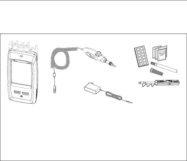
Chapter 5: Inspect Fiber Endfaces
How to Do the FiberInspector Test
87
How to Do the FiberInspector Test
Figure 35 shows the equipment for a FiberInspector test.
Figure 35. Equipment for the FiberInspector Test
BV174.EPS
Versiv 2 main unit with
CertiFiber Pro, OptiFiber Pro, or
blank module installed
FI-1000 video probe with USB
connector
Fiber cleaning supplies
AC adapter (optional)
AD
C
B

Versiv 2 Cabling Certification Product Family
Users Manual
88
To do the FiberInspector test
Refer to Figures 36 and 37.
1Connect the FI-1000 probe to the type A USB port on the side
of the tester.
2Install the correct tip on the probe.
3Clean the connector that you will inspect.
4Use the buttons on the probe or the tester to start the test:
Press the button on the probe.
If the FiberInspector test shows on in the test setup panel
on the home screen, tap TEST or press .
On the home screen, tap the TOOLS icon, then tap
FiberInspector.
5Insert the probe into the connector.
6To adjust the focus, turn the dial on the probe clockwise or
counterclockwise.
Figure 38 describes the FiberInspector display.
7To save the image, tap SAVE.
8On the SAVE RESULT screen, select End 1 or End 2, make sure
the Cable ID and End name are correct, then tap SAVE.
Saved FiberInspector results show these icons for End 1 and End
2:
Notes
The Auto Save function does not operate with the
FiberInspector test.
Continuous use of the video probe decreases the
battery life. To increase the battery life, connect
the ac adapter when you use the probe for more
than a few minutes.
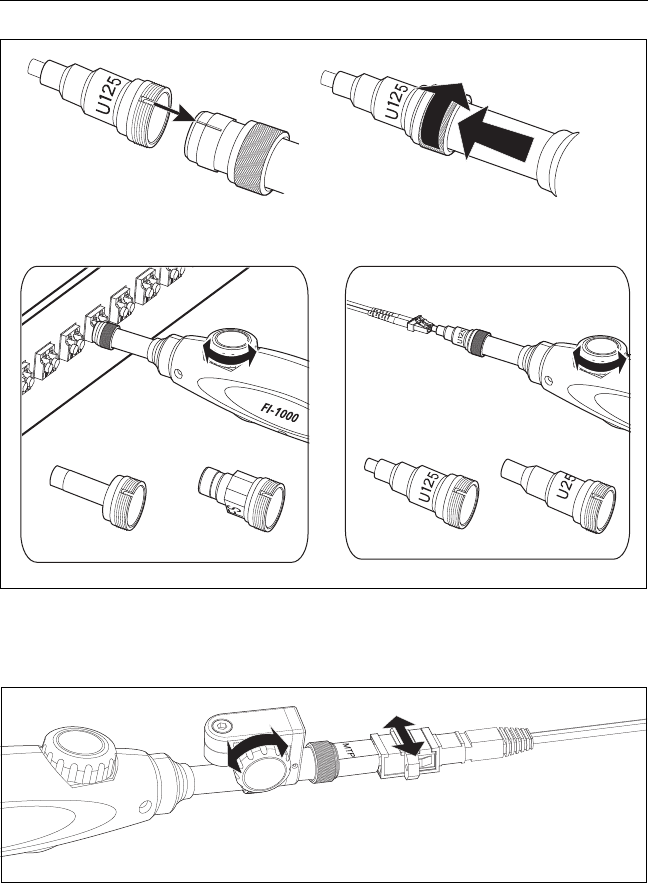
Chapter 5: Inspect Fiber Endfaces
How to Do the FiberInspector Test
89
GPU168.EPS
Figure 36. How to Use the FI-1000 Probe
GPU175.EPS
Figure 37. How to Use the Optional MPO/MTP® Inspection Tip
LC SC LC SC
Turn the dial to move the
view of the endface.
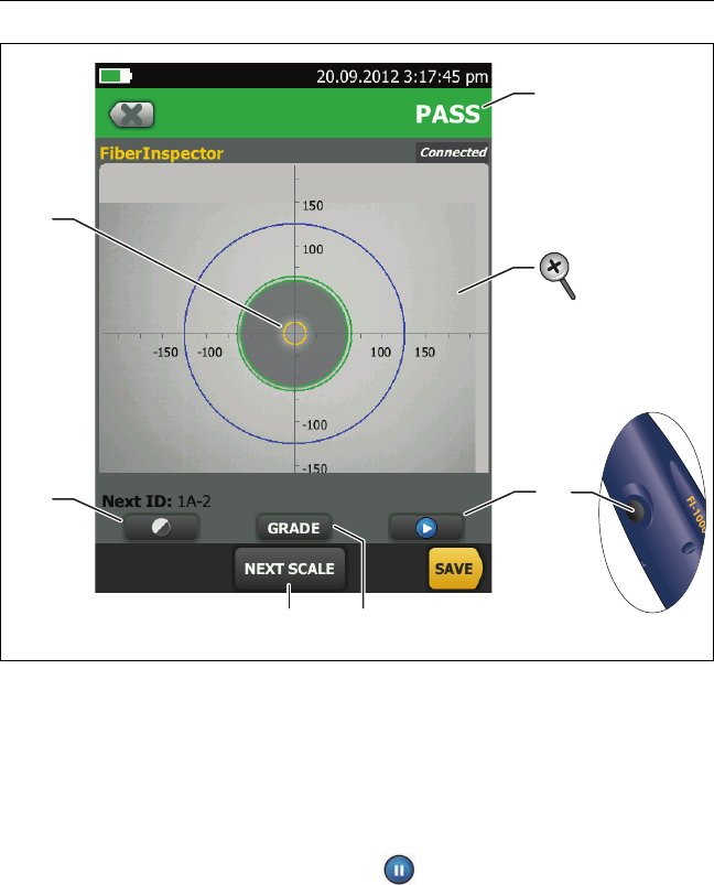
Versiv 2 Cabling Certification Product Family
Users Manual
90
GPU25.EPS
Figure 38. FiberInspector Image with Manual Grading Selected
Note
To see the buttons for the measurement axes and
core scales and to change the magnification of the
screen, you must first tap to put the screen in
still mode.
You can use the round, horizontal, and vertical scales to
measure the size of the fiber core and cladding. You can also
measure the size of particles, scratches, and other defects on
the endface.
B
A
DC
F
E
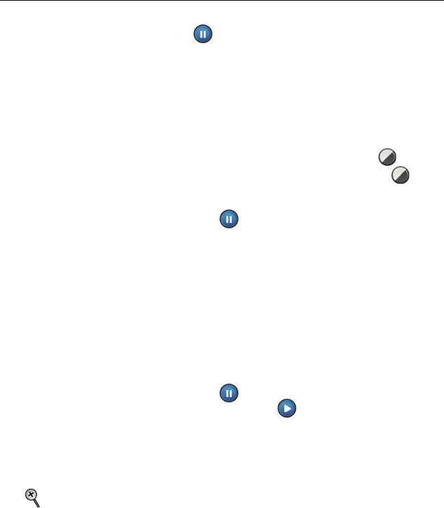
Chapter 5: Inspect Fiber Endfaces
How to Do the FiberInspector Test
91
To show the scales, tap , then tap SCALE ON (). Drag the
image to the center of the screen if necessary.
Outer, blue ring: 250 μm
Middle, green rings: 120 μm and 130 μm
Inner, yellow rings: 25 μm and 62.5 μm (to change the size,
tap NEXT SCALE)
To adjust the brightness or contrast of the image, tap , then
move the bars on the controls. To hide the controls, tap
again.
To show the scales (), tap , then tap SCALE ON. To change
the size of the measurement ring for the fiber core, tap NEXT
SCALE.
Manual limit selected: To give a PASS or FAIL grade to the
image, tap GRADE. See .
Test limit selected: To see an analysis of the defects, tap
ANALYZE. See “Automatic Analysis of Scratches and Defects”
on page 92.
To put the screen in still mode and turn off the probe, press the
button on the probe or tap . To turn the probe on again,
press the button on the probe or tap .
To give the image a grade of PASS or FAIL, tap GRADE (). If you
set the grade to FAIL, then save the image, the ID for the image
is in the list of tests to do again.
To zoom in and out, use the pinch, reverse-pinch, and double-
tap gestures on the touchscreen. See Figure 3 on page 16.

Versiv 2 Cabling Certification Product Family
Users Manual
92
Automatic Analysis of Scratches and Defects
Note
This function operates correctly only with the
FI-1000 probe.
When you select a limit for the FiberInspector test, the tester can
compare the size, location, and number of scratches and defects
to the limit’s criteria. Limits for the FiberInspector test are from
standards such as IEC 61300-3-35. The limits specify the maximum
size and number of scratches and defects allowed in the core,
cladding, adhesive, and contact zones on the fiber endface.
To do an endface analysis
1Make sure the test setup shows the correct FiberInspector test
limit.
2Do the FiberInspector test.
3Make sure the image is in focus, then tap ANALYZE.
The tester highlights the scratches and defects in red or green
(see Figure 39):
Red: FAIL. The scratch or defect is larger than the
maximum size that the limit allows, is closer to the fiber
core than the limit allows, or there are more scratches or
defects than the limit allows.
Green: PASS. The limit allows the scratch or defect
because it is too small or too far from the core to cause
problems, or there are fewer than the maximum allowed
number of scratches or defects of that size.
See Figure 39:
A defect, such as a particle of dirt, a chip, or a pit. This defect
is red because it is larger than the limit allows.
The measurement rings show after you tap ANALYZE. The sizes
of the rings are specified by the limit. To specify different sizes,
make a custom endface limit. See the Technical Reference
Handbook.
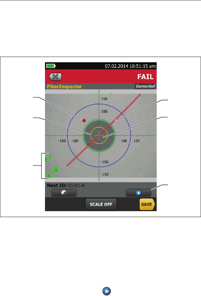
Chapter 5: Inspect Fiber Endfaces
Automatic Analysis of Scratches and Defects
93
WCaution
If a defect is possibly a dirt particle, clean the
endface and do the inspection again. You must
remove all loose particles because they can move
into the core when you make connections.
GPU167.EPS
Figure 39. FiberInspector Image with Defect Analysis
These defects are green because they are too far away from the
core to cause problems.
This scratch is red because it goes through the fiber core.
This defect is green because the limit allows a maximum of five
defects of that size or smaller in the cladding area.
To do the analysis again, tap then tap ANALYZE.
C
A
B
F
E
D