Fluke Electronics VERSIV2 CableAnalyzer User Manual Verisiv Part 2
Fluke Electronics CableAnalyzer Verisiv Part 2
Contents
- 1. User Manual DSX 302
- 2. User Manual Statement
- 3. User Manual Verisiv Part 1
- 4. User Manual Verisiv Part 2
- 5. User Manual Verisiv Part 3
User Manual Verisiv Part 2

Versiv 2 Cabling Certification Product Family
Users Manual
94
Fiber Tests with Two Main Testers
If you have two main testers, you can use FiberInspector video
probes at both ends of the cabling for faster inspections of fiber
endfaces.
You can also use the second main tester as a remote tester for
loss/length tests with CertiFiber Pro modules.
To use a main tester as a remote
Tap TOOLS then tap Main as Remote.
95
Chapter 6: Certify Fiber Cabling
WWarningX*
Before you use the tester, read the safety
information that starts on page 5.
Overview of Features
The Fluke Networks CertiFiber® Pro Optical Loss Test Set (OLTS)
modules attach to Versiv™ 2 main and remote units to make
rugged, hand-held testers that let you certify, troubleshoot, and
document optical fiber cabling installations. The testers include
these features:
Measures optical power loss and length on dual-fiber,
multimode cabling at 850 nm and 1300 nm (CFP-MM) or on
dual-fiber singlemode cabling at 1310 nm and 1550 nm
(CFP-SM). The four-wavelength module (CFP-QUAD) measures
at 850 nm, 1300 nm, 1310 nm, and 1550 nm.
Interchangeable connector adapters on input and output
ports let you make reference and test connections that agree
with ISO standards for most SFF (small form factor)
connectors.
Visual fault locator helps you find breaks, bad splices, and
bends and verify fiber continuity and polarity.
Optional FiberInspector™ video probe lets you inspect fiber
endfaces and save the images in test reports.
You can save approximately 30,000 fiber test results in the
tester’s internal memory. You can save more results on a
removable flash drive.
H
F
G
W*
B
N
M
I
O
CDE
L
J
K
A
Versiv 2 Cabling Certification Product Family
Users Manual
96
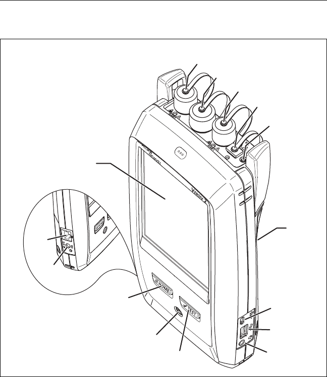
Connectors, Keys, and LEDs
BV123.EPS
Figure 40. Main Tester Connectors, Keys, and LEDs
(CFP-QUAD module shown)
LCD display with touchscreen
Singlemode output port with removable connector adapter
and dust cap. This port transmits optical signals for loss and
length measurements.

Chapter 6: Certify Fiber Cabling
Connectors, Keys, and LEDs
97
The LED below the output port is red when the port transmits
1310 nm and green for 1550 nm.
Input port with removable connector adapter and dust cap.
This port receives optical signals for loss, length, and power
measurements.
Multimode output port with removable connector adapter and
dust cap. This port transmits optical signals for loss and length
measurements.
The LED below the output port is red when the port transmits
850 nm and green for 1300 nm.
Universal fiber connector (with dust cap) for the visual fault
locator. The connector accepts 2.5 mm ferrules. The LED below
the connector shows the locator’s mode.
Button to manually control the output ports ( and ) and the
visual fault locator ().
Micro-AB USB port: This USB port lets you connect the tester to a
PC so you can upload test results to the PC and install software
updates in the tester.
Type A USB port: This USB host port lets you save test results on
a USB flash drive, connect the FI-1000 video probe to the tester.
Headset jack
: Starts a test. To start a test, you can also tap TEST on the
display.
: Power key
: Press to go to the home screen.
Connector for the AC adapter. The LED is red when the battery
charges, and green when the battery is fully charged. The LED is
yellow if the battery will not charge. See “Charge the Battery”
on page 11.
RJ45 connector: Lets you connect to a network for access to Fluke
Networks cloud services.
F
G
W*
D
B
E
L
A
H
M
C
I
J
K
Versiv 2 Cabling Certification Product Family
Users Manual
98
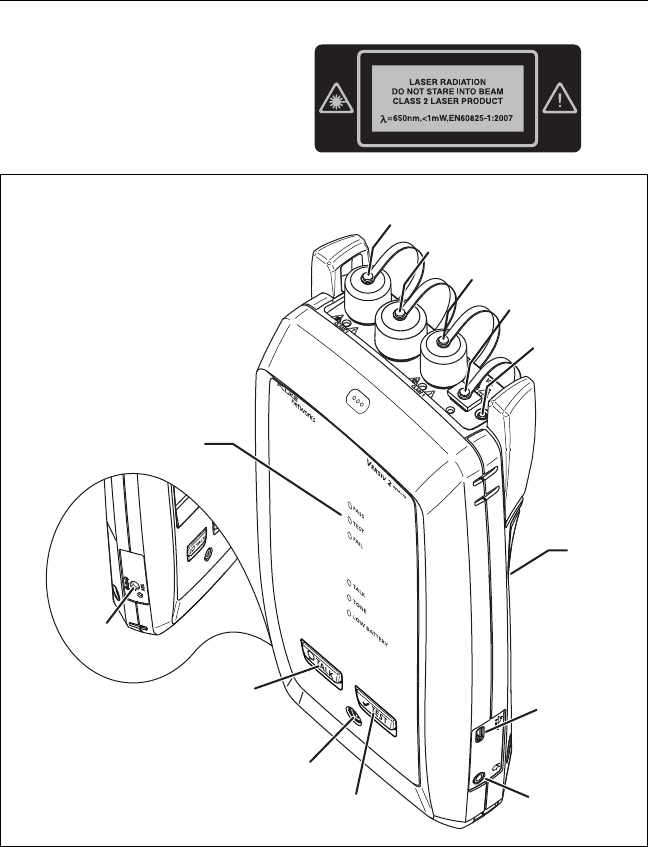
BV136.EPS
Figure 41. Remote Tester Connectors, Keys, and LEDs
(CFP-QUAD module shown)
PASS LED comes on when a test passes.
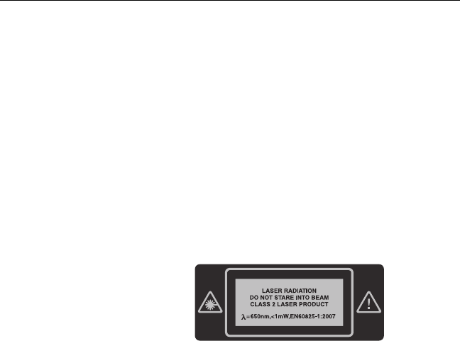
Decal with laser safety
information.

Chapter 6: Certify Fiber Cabling
Connectors, Keys, and LEDs
99
TEST LED comes on during a test and when you manually turn
on one of the output ports ().
FAIL LED comes on when a test fails.
TALK LED comes on when the talk function is on. The LED
flashes until the main tester accepts the request to talk.
TONE LED flashes if you press when a main tester is not
connected to the remote or is in Far End Source mode.
LOW BATTERY LED comes on when the battery is low.
The LEDs also have these functions:
Battery gauge (see Figure 1 on page 12)
Volume indicator for the TALK function
Progress indicator for software updates
Singlemode output port with removable connector adapter
and dust cap. This port transmits optical signals for loss and
length measurements.
The LED below the output port is red when the port transmits
1310 nm and green for 1550 nm.
Input port with removable connector adapter and dust cap.
This port receives optical signals for loss, length, and power
measurements.
Multimode output port with removable connector adapter and
dust cap. This port transmits optical signals for loss and length
measurements.
The LED below the output port is red when the port transmits
850 nm and green for 1300 nm.
Universal fiber connector (with dust cap) for the visual fault
locator. The connector accepts 2.5 mm ferrules. The LED below
the connector shows the locator’s mode.
Button to manually control the output ports ( and ) and the
visual fault locator ().
Versiv 2 Cabling Certification Product Family
Users Manual
100
Micro-AB USB port: This USB port lets you connect the tester to a
PC so you can install software updates in the tester.
Headset jack
: Starts a test.
: Power key
: Press to use the headset to speak to the person at
the other end of the link. Press again to adjust the volume. To
turn off the talk function, hold down .
Connector for the AC adapter. The LED is red when the battery
charges, and green when the battery is fully charged. The LED is
yellow if the battery will not charge. See “Charge the Battery”
on page 11.
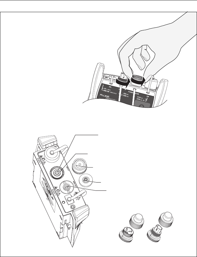
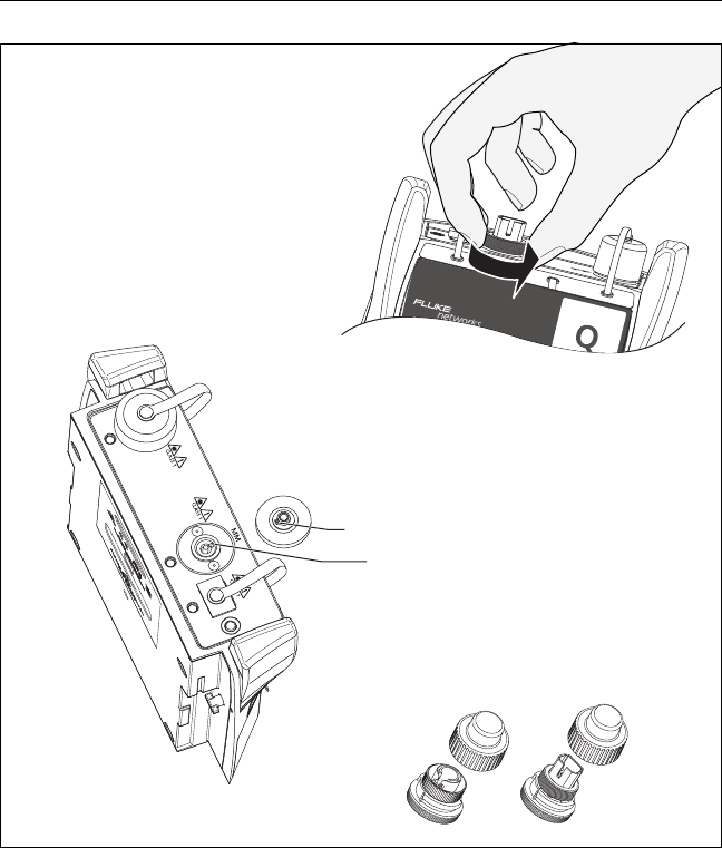
How to Remove and Install the Connector
Adapters
You can change the connector adapters on the input ports of the
modules to connect to SC, ST, LC, and FC fiber connectors. You
can remove the adapter on the output port to clean the fiber
endface in the port. See Figure 42.
Decal with laser safety
information.
Chapter 6: Certify Fiber Cabling
How to Remove and Install the Connector Adapters
101
GPU135.EPS
Figure 42. How to Remove and Install the Connector Adapters
LC SC
Keep extra adapters in
the containers provided.
WCaution
Do not touch the
photodiode lens.
WCaution
Turn only the collar on the adapter.
Do not use tools to remove or install
the adapters.
Slot
Key
Key
Slot
Put the key into the slot
before you turn the collar
on the adapter.
Versiv 2 Cabling Certification Product Family
Users Manual
102
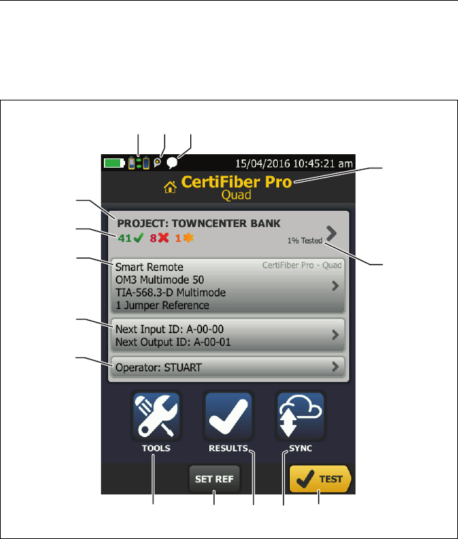
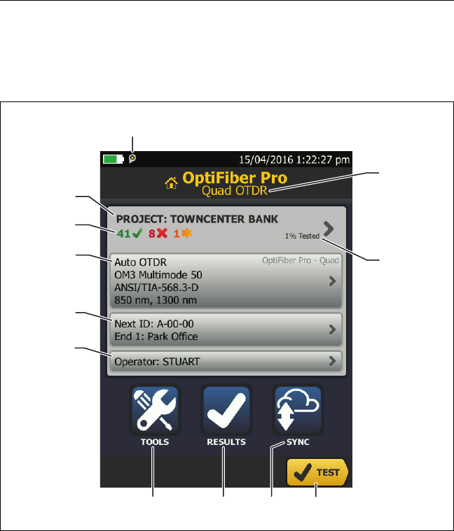
The CertiFiber Pro Home Screen
The home screen (Figure 43) shows important test settings. Before
you do a test, make sure these settings are correct.
GPU117.EPS
Figure 43. The Home Screen for CertiFiber Pro Modules
PROJECT: The project contains the settings for a job and helps
you monitor the status of a job. When you save test results, the
tester puts them in the project. Tap the PROJECT panel to edit
the project settings, select a different project, or make a new
project.
A
D
B
E
K
J
C
L
F
MN
GH
O
I

Chapter 6: Certify Fiber Cabling
The CertiFiber Pro Home Screen
103
Shows a summary of the test results in the project:
The number of tests that passed.
The number of tests that failed.
The test setup panel shows the settings the tester will use when
you tap TEST or press .
To change these settings, tap the panel, select the test on the
CHANGE TEST screen, tap EDIT, select different settings on the
TEST SETUP screen, then tap SAVE. See Table 6 on pages 113
and 114.
Note
You can set up tests for any module that the
tester can use, even when no module is attached.
Next ID: The Next ID panel shows the ID that the tester gives to
the next test results you save. For Smart Remote mode, this
panel shows IDs for main tester’s input and output fibers.
Tap Next ID to do these tasks:
Enter an ID, select a different ID in the ID set, select a
different set of IDs, or make a new set. The tester adds the
IDs and ID sets you make to the project that shows on the
home screen.
Turn Auto Save on or off.
Operator: The name of the person who does the job. You can
enter a maximum of 20 operator names. For each operator you
can also enter the email address that the operator will use as an
ID to sign in to LinkWare Live.
TOOLS: The TOOLS menu lets you set the reference for fiber
tests, see the status of the tester, and set user preferences such as
the language and the display brightness.
SET REF: Tap SET REF to set the reference and verify your test
reference cords for loss/length tests.
Versiv 2 Cabling Certification Product Family
Users Manual
104
RESULTS: Tap RESULTS to see and manage the results that are
saved in the tester.
SYNC: Tap SYNC to sync projects with LinkWare Live.
TEST: Tap TEST to do the test shown in the test setup panel.The
percentage of the tests in the project that are completed. The
tester uses the number of available IDs to calculate this
percentage. See Figure 90 on page 226. % Tested does not show
if your project contains only a Next ID list. See “About Next ID
Sets” on page 225 for more information about the Next ID list.
The type of module attached to the tester.
This icon shows when the input and output ports on the
tester’s CertiFiber Pro module are connected to the ports on the
remote’s CertiFiber Pro module, the remote tester is turned on,
and Smart Remote or Loopback mode is selected.
The asset management icon shows when the owner of a
LinkWare Live account has enabled the asset management
service on the tester. See “About the Asset Management Service”
on page 238.
This icon shows when the talk function is on. To use the talk
function:
1Connect the main and remote testers together through a
duplex fiber link.
2Connect headsets to the headset jacks on the testers.
3Press the button on one of the headset microphones or
press on the remote, then speak into the
microphone.

Chapter 6: Certify Fiber Cabling
Requirements for Reliable Fiber Test Results
105
Requirements for Reliable Fiber Test Results
To get reliable fiber test results and make sure your tester meets
its accuracy specifications, you must use the correct procedures:
Use proper cleaning procedures to clean all fiber connectors
before every use. See Chapter 4.
Set the reference frequently. See “About the Reference for
Fiber Tests” on page 106.
Use only test reference cords that comply with ISO/IEC
14763-3. Measure the loss of the cords frequently. See “About
Test Reference Cords and Mandrels” on page 108.
For multimode fiber, make sure you use the encircled flux test
reference cords (EF-TRCs) or standard mandrels correctly. See
“About the EF-TRC (Encircled-Flux Test Reference Cords)” on
page 108 and “TRCs Necessary for Links with APC Connectors”
on page 111.
Keep the tester’s software current. The latest software is
available on the Fluke Networks website. See “Update the
Software” on page 243.
Make sure you select the correct fiber type and test limit for
the job, and the index of refraction for the fiber is correct. See
Table 6 on page 113.
Make sure the battery is fully charged.
Send the modules to a Fluke Networks service center every 12
months for factory calibration.

Versiv 2 Cabling Certification Product Family
Users Manual
106
About the Reference for Fiber Tests
The reference procedure for fiber cable sets a baseline power
level for loss measurements. If the power level that enters the
fiber from the source changes, the reference and your loss
measurements will be incorrect. The power level can change, for
example, when the temperature at the job site increases or
decreases or when you disconnect then reconnect a test reference
cord at the tester’s output port. So, it is important to set the
reference frequently.
When to Set the Reference
Note
At the job site, turn on the testers and let them sit
for a minimum of 5 minutes before you set the
reference. Let them sit longer if they are above or
below ambient temperature.
The tester requires you to set the reference at these times:
When you change the CertiFiber Pro module in the main or
remote tester.
When you use a different remote tester.
When you change the Reference Method in the test setup.
Set the reference also at these times:
At the start of each day, at the job site, then at regular
intervals during the day. For example, set the reference when
you start tests on a different series of fibers.
When you connect a test reference cord to the module’s
output port or to another source, even if you connect the
same test reference cord you connected before.
When the tester tells you that the reference is out of date.
When a loss measurement is negative. This occurs when there
was a problem when you set the reference. For example, an
endface was dirty or the testers were cold.

Chapter 6: Certify Fiber Cabling
Requirements for Reliable Fiber Test Results
107
WCaution
Do not disconnect the test reference cords from
the modules’ output ports after you set the
reference. If you do, you will change the amount
of optical power that enters the fiber and the
reference will not be correct.
Good Reference Values
For Smart Remote and Loopback modes, these are the typical
ranges for reference values:
Multimode 50/125 μm fiber: -19.4 dBm to -26.5 dBm
Multimode 62.5/125 μm fiber: -17.5 dBm to -23.0 dBm
Singlemode fiber: -1.0 dBm to -6.0 dBm
For Far End Source mode with a CertiFiber Pro source, reference
values must be in these ranges:
Multimode 50/125 μm fiber: -19.4 dBm to -26.5 dBm
Multimode 62.5/125 μm fiber: -17.5 dBm to -23.0 dBm
Singlemode fiber: -1.0 dBm to -9.7 dBm
If your reference value is outside of the applicable range given
above, clean and inspect all connectors then set the reference
again. Do this even if the tester lets you use the value.
If your test reference cords and connectors are in good condition,
and you use the correct procedure to set the reference, the
reference value will not change by more than approximately
0.4 dBm.
How to See the Reference Values
After you set the reference, tap View Reference on the SET
REFERENCE screen.
After you do an Autotest, tap the result window for a fiber,
then tap VIEW REFERENCE.

Versiv 2 Cabling Certification Product Family
Users Manual
108
About Test Reference Cords and Mandrels
Use only test reference cords (TRCs) that have low loss:
Maximum loss for multimode TRCs: 0.15 dB
Maximum loss for singlemode TRCs: 0.25 dB
To make sure your test results are accurate as possible:
Inspect the endfaces of the TRCs every 24 to 48 tests and clean
them when necessary.
Use the TRC VERIFICATION wizard available for the 1 Jumper
and 3 Jumper reference methods to measure the losses of the
TRCs. The losses of the TRCs are included in the loss
measurements for links, so you must make sure the losses are
very small. The wizard saves the results of the TRC tests to show
that your TRCs were good. IDs for these results start with “TRC”,
show the date and time of the test, and have an for the test
result.
About the EF-TRC (Encircled-Flux Test Reference Cords)
The CFP-MM and CFP-QUAD kits includes the EF-TRC (encircled
flux test reference cords), which have signal conditioners on the
cords. When you use the EF-TRCs with the CertiFiber Pro
multimode modules, your tester complies with IEC 61280-4-1, ISO/
IEC 14763-3, and TIA-526-14-B standards for encircled flux.
Measurements made with compliant equipment change less than
10 % for losses of 1 dB or more when you make them at different
times or with different equipment that is also compliant.
Note
The IEC 61280-4-1, ISO/IEC 14763-3, and
TIA-526-14-B standards require your optical loss
test set to comply with encircled flux standards at
850 nm with 50 µm/125 µm fiber. The standards
recommend compliance at 850 nm with 62.5 µm/
125 µm fiber and at 1300 nm with 50 µm/125 µm
and 62.5 µm/125 µm fiber.
Chapter 6: Certify Fiber Cabling
Requirements for Reliable Fiber Test Results
109
WCaution
To prevent damage to fiber connectors, to
prevent data loss, and to make sure that your test
results are as accurate as possible:
Use the EF-TRC cords only with the CertiFiber Pro
modules or with sources approved by Fluke
Networks for use with the cords. If a source does
not have the correct LED and internal fibers, the
EF-TRC cords will not make launch conditions that
agree with encircled flux standards.
When you use the EF-TRCs, DO NOT use other mandrels.
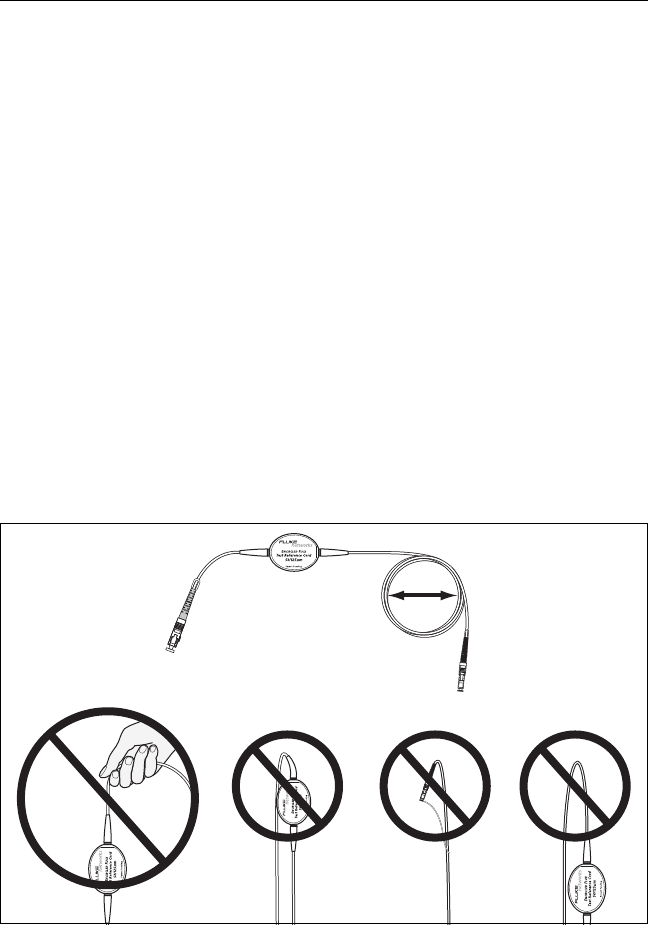
Always follow the handling guidelines given in Figure 44.
Put protective caps on all connectors when you do
not use them.
Use EF-TRCs that have the fiber core dimension
(50 µm or 62.5 µm) and type of connectors (SC, ST,
LC, or FC) that are the same as the fiber link. Do not
use EF-TRCs with hybrid patch cords to connect to
links that have other types of connectors.
GPU157.EPS
Figure 44. How to Prevent Damage to the EF-TRC Fiber Cables
Minimum bend
diameter:
1.2 in (30 mm)

Versiv 2 Cabling Certification Product Family
Users Manual
110
About APC Connectors
When you do tests on links with APC (angled physical contact)
connectors, use only test reference cords with APC connectors on
the ends connected to the link. If you connect non-APC
connectors to the link, the connectors will cause large reflections
that make loss measurements inaccurate.
For tests on links with APC connectors, use test reference cords
that also have APC connectors on the ends connected to the
tester’s input ports. This is necessary for the 1 jumper reference
method. You can connect APC connectors to the tester’s input
ports because the fiber does not touch the lens on the input port.
Note
Do not connect APC connectors to the tester’s
output ports. APC connectors will not damage the
ports, but they will not receive enough optical
power from the tester because the output ports
are designed for UPC connectors.
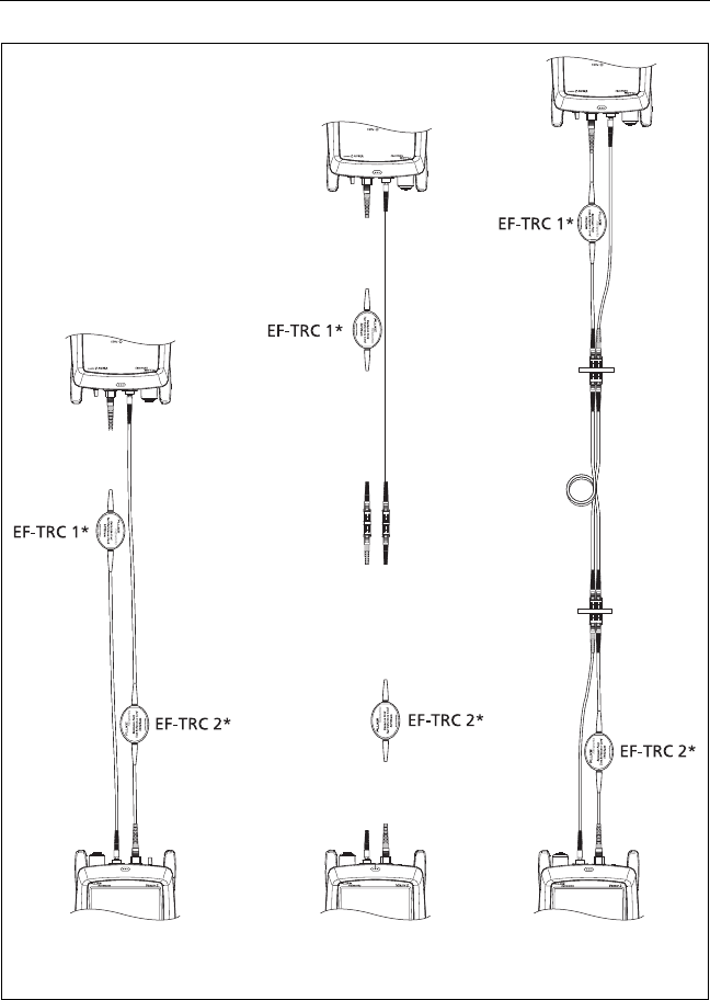
Figure 45 shows the TRCs necessary for tests on links with APC
connectors.
Chapter 6: Certify Fiber Cabling
Requirements for Reliable Fiber Test Results
111
BV166.EPS
Figure 45. TRCs Necessary for Links with APC Connectors
*Use the EF-TRCs only with multimode modules.
Fiber Link Test
Reference
TRC Verification
APC APC
APC
APC
APC
APC
APC
APC
APC
APC
APC
APC APC
APC
APC
APC
APC
APC
UPC
UPC
UPC
UPC
UPC UPC
Note
Connect only UPC connectors
to the tester’s output ports

Versiv 2 Cabling Certification Product Family
Users Manual
112
About Standard Mandrels
Standard mandrels make measurements of multimode power loss
more reliable than if you use no mandrels, but the measurements
do not comply with the standards for encircled flux. Fluke
Networks recommends that you always use only the EF-TRCs with
the CertiFiber Pro multimode modules so that your measurements
comply with EF standards.
If you must do tests in Far End Source mode with a different
multimode source, and the source is not approved by Fluke
Networks for use with the TRCs, use standard mandrels. Make
sure you use the size of mandrel that is correct for 50 μm or
62.5 μm fiber, and read all instructions for the source and
mandrel.
WCaution
If you use mandrels for tests on multimode fiber,
do not use test reference cords made from bend-
insensitive fiber. The mandrels possibly will not
remove all of the modes that can make your loss
measurements unreliable.
Settings for Fiber Tests
Table 6 gives descriptions of the settings for fiber tests. To set up
a project, which includes the settings in Table 6, cable IDs, and
operator names, see Chapter 11.
To set up a fiber test
1On the home screen, tap the test setup panel.
2On the CHANGE TEST screen, select a fiber test to change,
then tap EDIT.
Or to set up a new fiber test, tap NEW TEST. If no module is
installed, the MODULE screen shows. Tap the correct CertiFiber
Pro module.

Chapter 6: Certify Fiber Cabling
Settings for Fiber Tests
113
3On the TEST SETUP screen, tap the panels to change settings
for the test. See Table 6.
4On the TEST SETUP screen, tap SAVE when your test setup is
completed.
5On the CHANGE TEST screen, make sure the button next to
the test is selected, then tap USE SELECTED.
Table 6. Settings for Fiber Tests
Setting Description
Module Select the CertiFiber Pro module you will use.
Test Type Use Smart Remote mode for tests on duplex-fiber
cabling. See page 121.
Use Loopback mode for tests on patch cords and cable
spools. See page 129.
Use Far End Source mode for tests on individual fibers.
See page 137.
Bi-Directional Off: The tester does fiber tests in only one direction.
On: The tester does fiber tests in both directions. See “Bi-
Directional Tests” on page 146.
The Bi-Directional setting is not available for Far End
Source mode.
Fiber Type Select a fiber type that is correct for the type you will
test. To see a different group of fiber types, tap MORE,
then tap a group. To make a custom fiber type, tap
Custom in the Fiber Groups list. See the Technical
Reference Handbook.
Fiber Type
Settings
IOR: The tester uses the index of refraction to calculate
the optical length of the fiber. Each fiber type includes
the value specified by the manufacturer. To use a
different IOR, make a custom fiber type. See the
Technical Reference Handbook.
-continued-

Versiv 2 Cabling Certification Product Family
Users Manual
114
Test Limit Select the correct test limit for the job. To see a different
group of limits, tap MORE, then tap the name of a
group. To make a custom limit, tap Custom in the Limit
Groups list. See the Technical Reference Handbook.
Reference
Method
On the No. of Connectors/Splices screen, set the number
of jumpers you will use in each fiber path when you set
the reference. The dotted lines in the diagram on the
screen show you which parts of the link are included in
the test results.
The number of jumpers you use has these effects on loss
measurements:
1 Jumper: Loss measurements include the connections at
both ends of the link. The figures in this manual show 1
Jumper connections.
2 Jumper: Loss measurements include one connection at
one end of the link.
3 Jumper: Loss measurements do not include the
connections at the ends of the link. The tester measures
only the loss of the fiber.
This setting does not change the loss measurements, but
it can change the PASS/FAIL result for test limits that use
a calculated loss limit. For all test limits, the tester saves
this setting to show the reference method you used.
WCaution
Most cable manufacturers will give you a
warranty on a fiber installation only if you use
the 1 Jumper reference method when you
certify the installation.
Note
Different standards use different names for the
three methods. See Appendix A.
Table 6. Settings for Fiber Tests (continued)

Chapter 6: Certify Fiber Cabling
Settings for Fiber Tests
115
Connector Type Select the type of connector, such as SC or LC, used in the
cabling.
The tester uses this setting when you do bi-directional
tests. If you select a connector that has a threaded or
bayonet coupler, such as FC or ST, the tester waits for
you to confirm that the connection is complete before it
starts the second part of the test. If you select a quick-
release connector, such as SC or LC, the tester
automatically starts the test when you connect the fiber.
The tester also saves this setting to record the type of
connector you used. This setting does not change your
test results or any of the diagrams that the tester shows.
If the correct type is not in the list, select General.
Table 6. Settings for Fiber Tests (continued)

Versiv 2 Cabling Certification Product Family
Users Manual
116
No. of
Connectors/
Splices
The Total Connections and Splices settings are applicable
only if the selected test limit uses a calculated limit for loss.
Total Connections: Enter the total number of
connections that are in each path of the link. Do not
adjust the number for the Reference Method you use.
For example, if the link has 3 connections, enter “3” even
if you use the 2 or 3 Jumper reference method. When
the tester calculates the loss limit, it automatically
removes the losses of the connections you used to set the
reference.
Note
The CertiFiber Pro automatically adjusts the
number of connections for the Reference
Method you use. This is different from the DTX
CableAnalyzer, where you do not include the
reference connections in the number of
connectors.
Splices: Enter the number of splices in each path of the
link.
Jumper Reference: Enter the number of jumpers you will
use in each fiber path when you set the reference. The
dotted lines in the diagram on the screen show you
which parts of the link are included in the test results.
See Reference Method above.
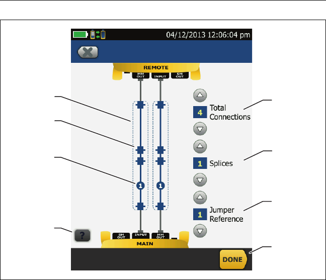
Figure 46 shows the No. of Connectors/Splices screen.
Figure 47 shows how to count the jumpers, connectors,
and splices for this setting.
TRC LENGTH
(Test reference
cord length)
You can enter length of your test reference cords when you
set the reference. To enter this value, tap TRC LENGTH on
the SET REFERENCE screen. The length you enter does not
change the test results. The tester saves the length with the
results to meet TIA reporting requirements.
Table 6. Settings for Fiber Tests (continued)
Chapter 6: Certify Fiber Cabling
Settings for Fiber Tests
117
GPU140.EPS
Figure 46. Screen to Set the Number of Connectors,
Splices, and Jumpers
Total Connections: Enter the total number of connections that
are in each path of the link. Do not adjust the number for the
Reference Method you use. For example, if the link has 3
connections, enter “3” even if you use the 2 or 3 Jumper
reference method. When the tester calculates the loss limit, it
automatically removes the losses of the connections you used
to set the reference.
Note
For links with MPO modules, each module is one
connector.
DA
C
H
G
E
B
F
Versiv 2 Cabling Certification Product Family
Users Manual
118
Splices: Enter the number of splices that are in each path of the
link.
Jumper Reference: Enter the number of jumpers you will use in
each fiber path when you set the reference. The dotted lines in
the diagram on the screen show you which parts of the link are
included in the test results. See Reference Method on page 114.
The dotted lines show you which parts of the link are included in
the test results.
Connector icons show the connections between the ends of the
link. If you enter 7 or more for the Total Connections setting, a
number inside of a connector icon shows the number of
connectors between the ends of the link. For example, if the
Total Connections setting is 7, a connector icon shows the
number 5 ( )
The round icon shows the number of splices in each path of the
link.
To see help for the screen, tap .
To save your settings, tap DONE.
Chapter 6: Certify Fiber Cabling
Settings for Fiber Tests
119
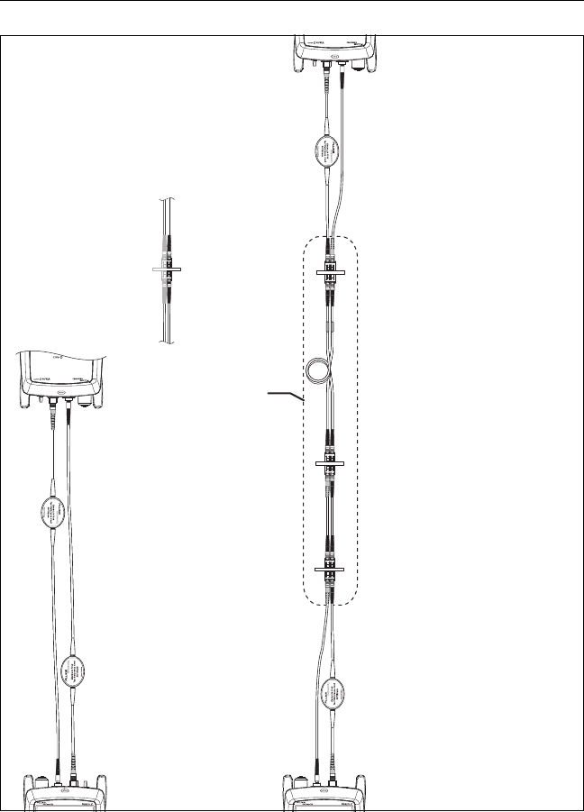
BV133.EPS
Figure 47. How to Count the Numbers of Connectors,
Splices, and Jumpers
Test connections
Total Connections: 3
(do not adjust for the
reference method)
Splices: 1
Connector or connection =
1 connector pair
Connector
Connector
Splice
Connector
Reference
connections
Jumpers: 1
Connectors
included in the
test results for
the 1 Jumper
reference
method

Versiv 2 Cabling Certification Product Family
Users Manual
120
About 1 Jumper Reference Connections
The reference and test connections shown in this manual give 1
jumper results. 1 jumper results include the loss of the fiber plus
the loss of the connections at both ends of the link. This is the
best method for tests on premises fiber installations. Premises
installations typically use patch cords at both ends of the link, and
connector loss is a large part of the total loss.
If you do not have the correct connector adapters, see Appendix B
for other connections that give 1 jumper results.
For descriptions of the 2 and 3 jumper reference connections, see
the Versiv 2 Technical Reference Handbook.
WCaution
Most cable manufacturers will give you a
warranty on a fiber installation only if you use a 1
Jumper reference when you certify the
installation.
Note
If you use a 2 Jumper reference, the Wizard for
the reference procedure does not show steps for
the TRC verification. To save test results for the
TRCs, do the tests manually.

Chapter 6: Certify Fiber Cabling
Autotest in Smart Remote Mode
121
Autotest in Smart Remote Mode
Use Smart Remote mode to do tests on dual-fiber cabling.
In this mode, the tester measures loss and length on two fibers at
two wavelengths. If you turn on the Bi-Directional function and
swap the fibers halfway through the test, the tester makes
measurements in both directions.
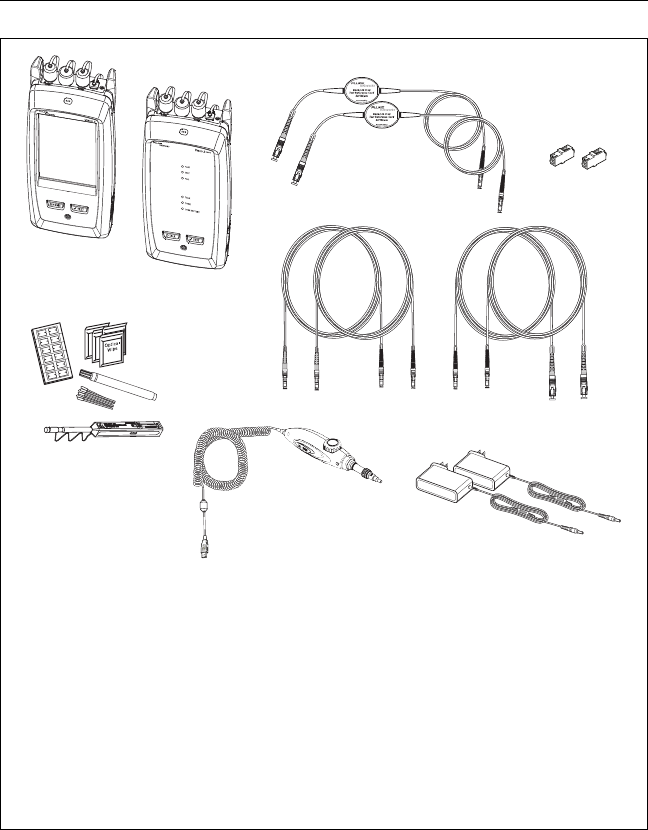
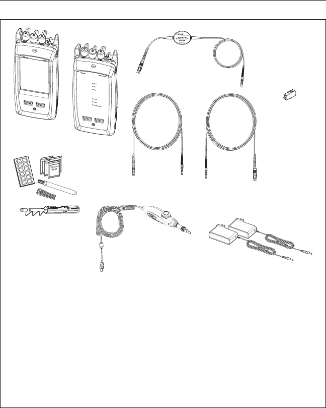
Figure 48 shows the equipment for tests in Smart Remote mode.
Fiber Tests with Two Main Testers
If you have two main testers, you can use one as a remote tester
for tests in Smart Remote mode. This also lets you use
FiberInspector video probes at both ends of the cabling for faster
inspections of fiber endfaces.
To use a main tester as a remote
Tap TOOLS then tap Main as Remote.
Versiv 2 Cabling Certification Product Family
Users Manual
122
Figure 48. Equipment for Autotests in Smart Remote Mode
BV128.EPS
Main and remote Versiv 2 units
with CertiFiber Pro modules
installed
For multimode fiber: two EF-TRC
test reference cords
Two singlemode adapters
For multimode fiber: two test
reference cords. For singlemode
fiber: four test reference cords.
Fiber cleaning supplies
FI-1000 video probe with USB
connector
AC adapters (optional)
A
B
D
C
EF
G

Chapter 6: Certify Fiber Cabling
Autotest in Smart Remote Mode
123
Step 1: Set the Reference in Smart Remote Mode
1-1 Turn on the tester and remote and let them sit for a
minimum of 5 minutes. Let them sit longer if they are above
or below ambient temperature.
1-2 Make sure that the home screen shows the correct settings for
the job, and the test type is Smart Remote.
To make sure that other settings are correct, tap the test
setup panel, make sure the correct test is selected on the
CHANGE TEST screen, then tap EDIT to see more settings.
Table 6 on page 113 describes the settings.
1-3 Clean and inspect the connectors on the tester, remote, and
test reference cords.
1-4 On the home screen tap SET REF.
1-5 On the SET REFERENCE screen, tap RUN WIZARD.
Notes
To only set the reference, and not measure the
loss of your test reference cords, tap SKIP WIZARD
on the SET REFERENCE screen.
Fluke Networks recommends that you measure
the loss of your test reference cords each time you
set the reference.
1-6 Make the connections to set the reference, as shown on the
screen and in Figure 49, then tap NEXT to see the completed
connections.
Notes
The SET REFERENCE screen shows reference
connections for the selected reference method.
Figure 49 shows connections for a 1 Jumper
reference.
When you set the reference, align the testers as
shown in Figure 49 to keep the fibers as straight as
possible.
-continued-
Versiv 2 Cabling Certification Product Family
Users Manual
124
BV122.EPS
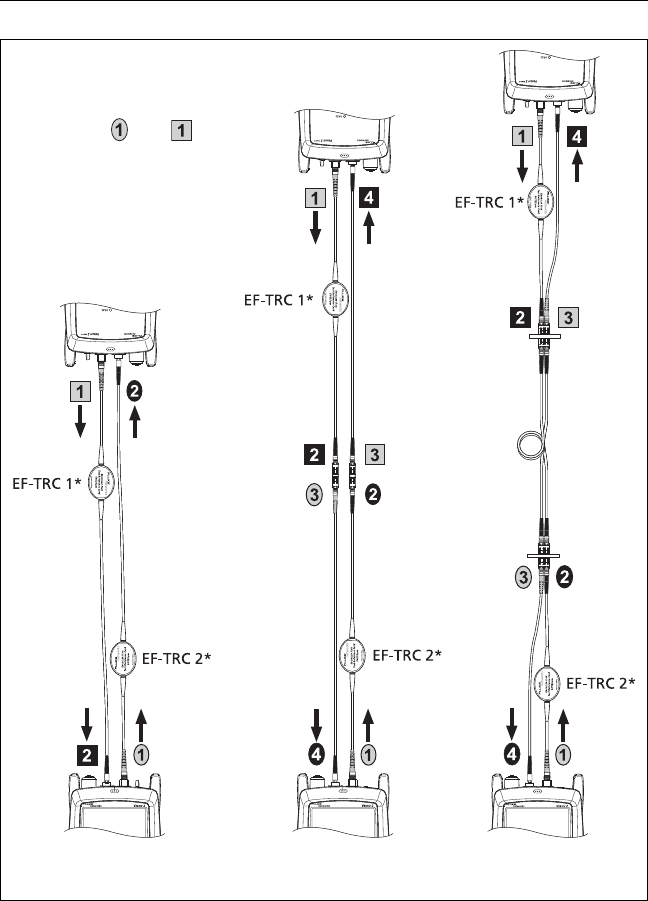
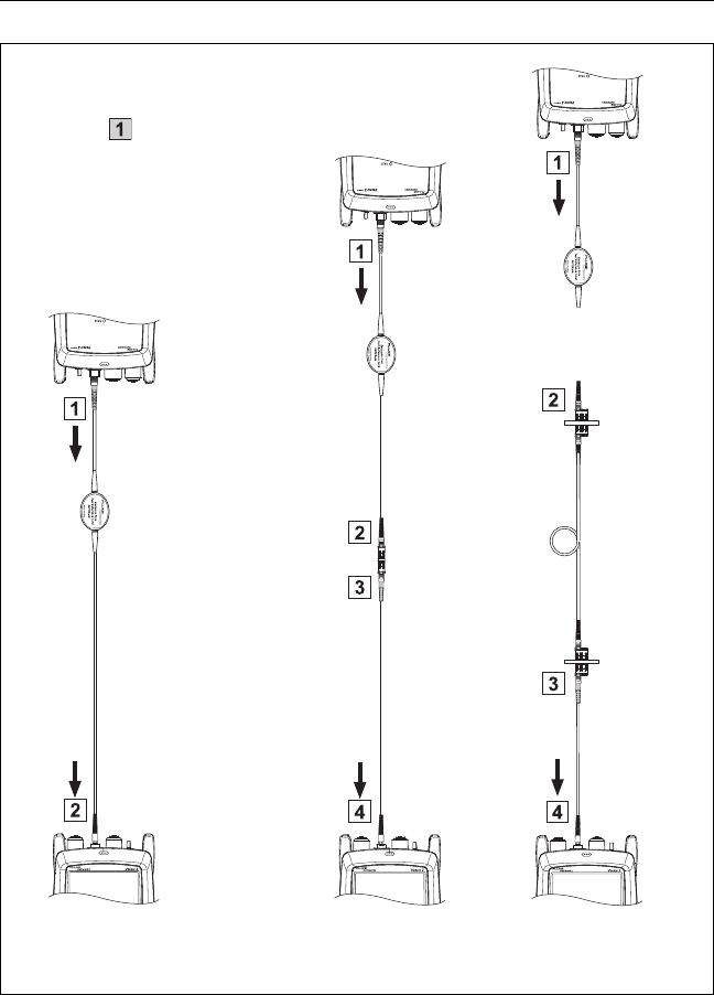
Figure 49. Connections for Smart Remote Mode
(1 Jumper Reference, Multimode Fiber)
WCaution
Do not disconnect the
outputs ( and ) after
you set the reference.
When you use the EF-TRCs,
DO NOT use other
mandrels.
Fiber
link
Test
reference
cord
Test
reference
cord
*Use the EF-TRCs only with multimode modules.
Fiber Link Test
Reference
TRC Verification

Chapter 6: Certify Fiber Cabling
Autotest in Smart Remote Mode
125
1-7 To enter the length of the test reference cords you will add to
connect to the link, tap TRC LENGTH on the SET REFERENCE
screen. The length you enter does not change the test results.
The tester saves the length with the results to meet TIA
reporting requirements.
1-8 Tap SET REFERENCE.
If reference values are unacceptable, you can use the
FiberInspector probe to inspect connectors. To turn on the
probe, press the button on the probe. To go back to the
reference screen, tap .
1-9 If you did not use the connection wizard, go to step 3.
Step 2: Measure the Loss of the Test Reference Cord You
Will Add
WCaution
If you disconnected a test reference cord from the
output of the tester or remote, you must set the
reference again to make sure your measurements
are reliable.
2-1 On the SET REFERENCE screen, when the reference procedure
is completed, tap NEXT.
2-2 Disconnect the test reference cords from the INPUT ports on
the tester and remote, then use test reference cords and
adapters to make the connections to verify the TRCs, as shown
on the screen and in Figure 49.
2-3 Tap TRC VERIFICATION. The tester measures and saves the loss
of the test reference cords you added. The IDs for these results
start with “TRC”, show the date and time of the test, and have
an for the test result.
The tester shows a warning if the loss of a TRC is more than
these limits:

Versiv 2 Cabling Certification Product Family
Users Manual
126
Maximum loss for multimode TRCs: 0.15 dB
Maximum loss for singlemode TRCs: 0.25 dB
If the tester shows a warning, clean and inspect the
connectors on the TRCs in the path that has too much loss,
make sure the cords are straight as shown in Figure 49, then
do the TRC verification again.
Step 3: Do an Autotest in Smart Remote Mode
WCaution
If you disconnected a test reference cord from the
output of the tester or remote, you must set the
reference again to make sure your measurements
are reliable.
3-1 On the SET REFERENCE screen, when the set reference or
TRC verification procedure is completed, tap NEXT to see
how to connect to the link under test.
3-2 Clean and inspect all the connectors.
3-3 Make the connections to do the test on the fiber link, as shown
on the screen and in Figure 49, then tap HOME.
3-4 Tap TEST on the main tester or press on the main or
remote tester.
If the CHECK FIBER CONNECTIONS screen shows an open
fiber:
Make sure that all connections are good and no fibers
have damage. Use the VFL to make sure the fibers in the
link have continuity.
Make sure that the remote is on.
Switch the connections at one end of the patch panel.

Chapter 6: Certify Fiber Cabling
Autotest in Smart Remote Mode
127
If you are not sure you are connected to the correct
fibers, connect the main tester’s INPUT fiber to different
connections until the test continues or the INPUT fiber
on the display is green. Then if necessary, connect the
remote’s INPUT fiber to different connections until the
test continues.
3-5 If Bi-Directional is On: Halfway through the test, the tester
tells you to switch the input and output fibers. See “Bi-
Directional Tests” on page 146.
3-6 Save the result:
If Auto Save is on, the tester uses the next two IDs to save
the results for the two fibers.
If Auto Save is off, tap SAVE if the test passed or FIX
LATER if the test failed. The SAVE RESULT screen shows
the next two IDs available. You can change the IDs if
necessary.
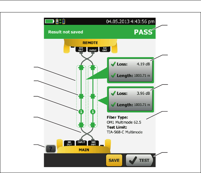
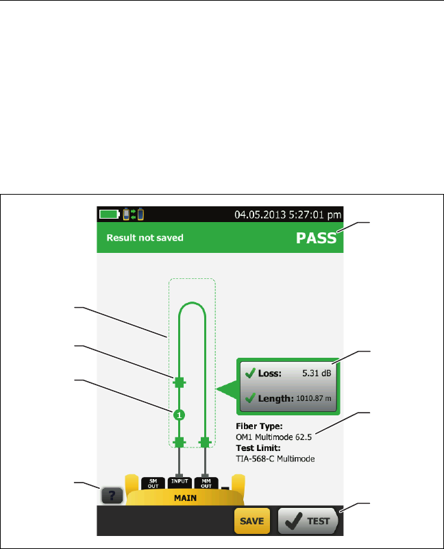
Autotest Results for Smart Remote Mode
Unsaved results show the results for both fibers. See Figure 50.
The overall result for the Autotest.
The fiber IDs and the loss and length measurements for the
fibers:
The result exceeds the limit.
The result is within the limit.
The selected test limit does not have a limit for the test.
To see the results, limits, and margins for a fiber, tap the
window.
The settings the tester used for the test.
Versiv 2 Cabling Certification Product Family
Users Manual
128
GPU118.EPS
Figure 50. Result for Smart Remote Mode
(Unsaved Bi-Directional Results Shown)
Note
The length shown for each fiber is half of the total
length of both fibers.
The dashed lines are around the connectors and fiber that are
included in the loss and length results. Gray connectors and
fibers are not included because you used them to set the
reference.
Connector icons show the number you entered for the TOTAL
CONNECTIONS setting on the No. of Connectors/Splices
screen (Figure 46 on page 117). For Figure 50, the TOTAL
CONNECTIONS setting is 4.
D
A
B
C
I
H
EB
F
G

Chapter 6: Certify Fiber Cabling
Autotest in Loopback Mode
129
The round icon shows the number of splices entered for the
SPLICES setting on the No. of Connectors/Splices screen.
Bi-directional results show the fibers crossed at the main and
remote ports. The fibers show the connections as they are at the
end of the test.
To see help for the screen, tap .
When more than one button shows at the bottom of the screen,
the tester highlights one in yellow to recommend which one to
tap. See “Buttons to Do Tests and Save Results” on page 17.
Fiber IDs for Saved Results in Smart Remote Mode
If Auto Save is On and the test passed, the tester saves two
records, one for each fiber. The records have the next two IDs in
the ID list.
If you must change the ID for a fiber before you save results, set
Auto Save to Off before you do the test. Then, on the SAVE
RESULT screen, tap the Input Fiber ID or Output Fiber ID window.
Autotest in Loopback Mode
Use Loopback mode to do tests on spools of cable and segments
of uninstalled cable.
In this mode, the tester measures loss and length at two
wavelengths. If you turn on the Bi-Directional function and swap
the fibers halfway through the test, the tester makes
measurements in both directions.
Figure 48 shows the equipment for tests in Loopback Mode.
Versiv 2 Cabling Certification Product Family
Users Manual
130
Figure 51. Equipment for Autotests in Loopback Mode
BV129EPS
Main Versiv 2 unit with
CertiFiber Pro module installed
For multimode fiber: one EF-TRC
test reference cord
Two singlemode adapters
For multimode fiber: one test
reference cord. For singlemode
fiber: two test reference cords.
Fiber cleaning supplies
FI-1000 video probe with USB
connector
AC adapter (optional)
A
B
C
E
D
FG

Chapter 6: Certify Fiber Cabling
Autotest in Loopback Mode
131
Step 1: Set the Reference in Loopback Mode
1-1 Turn on the tester and let it sit for a minimum of 5 minutes.
Let it sit longer if it is above or below ambient temperature.
1-2 Make sure that the home screen shows the correct settings for
the job, and the test type is Loopback.
To make sure that other settings are correct, tap the test
setup panel, make sure the correct test is selected on the
CHANGE TEST screen, then tap EDIT to see more settings.
Table 6 on page 113 describes the settings.
1-3 Clean and inspect the connectors on the tester and test
reference cords.
1-4 On the home screen tap SET REF.
1-5 On the SET REFERENCE screen, tap RUN WIZARD.
Notes
To only set the reference, and not measure the
loss of your test reference cord, tap SKIP WIZARD
on the SET REFERENCE screen.
Fluke Networks recommends that you measure
the loss of your test reference cord each time you
set the reference.
1-6 Make the connection to set the reference, as shown on the
screen, then tap NEXT to see the completed connections.
Figure 52 also shows the completed connections.
Notes
The SET REFERENCE screen shows reference
connections for the selected reference method.
Figure 52 shows connections for the 1 Jumper
reference.
When you set the reference, keep the fiber as
straight as possible.
-continued-
Versiv 2 Cabling Certification Product Family
Users Manual
132
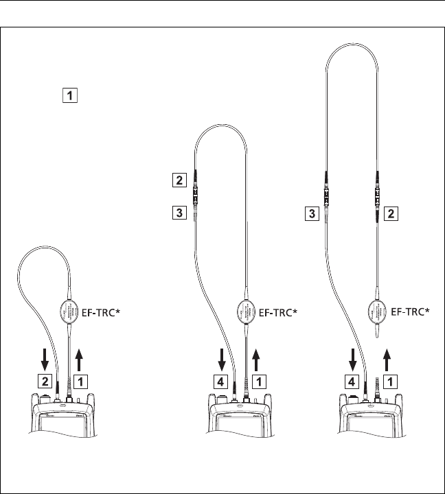
BV131.EPS
Figure 52. Connections for Loopback Mode
(1 Jumper Reference, Multimode Fiber)
Test
reference
cord
WCaution
Do not disconnect the
output ( ) after you set
the reference.
When you use the EF-TRCs,
DO NOT use other
mandrels.
Fiber
Fiber Test
Reference
TRC Verification
*Use the EF-TRCs only with multimode modules.
Chapter 6: Certify Fiber Cabling
Autotest in Loopback Mode
133
1-7 To enter the length of the test reference cord you will add to
connect to the fiber under test, tap TRC LENGTH on the SET
REFERENCE screen. The length you enter does not change the
test results. The tester saves the length with the results to meet
TIA reporting requirements.
1-8 Tap SET REFERENCE.
If reference values are unacceptable, you can use the
FiberInspector probe to inspect connectors. To turn on the
probe, press the button on the probe. To go back to the
reference screen, tap .
1-9 If you did not use the connection wizard, go to step 3.
Step 2: Measure the Loss of the Test Reference
Cord You Will Add
WCaution
If you disconnected the test reference cord from
the output of the tester, you must set the
reference again to make sure your measurements
are reliable.
2-1 On the SET REFERENCE screen, when the reference procedure
is completed, tap NEXT.
2-2 Disconnect the test reference cord from the INPUT port on the
tester, then use a test reference cord and adapter to make the
connections to verify the TRCs, as shown on the screen and in
Figure 52.
2-3 Tap TRC VERIFICATION. The tester measures and saves the loss
of the test reference cord you added. The ID for this result
starts with “TRC”, shows the date and time of the test, and has
an for the test result.
The tester shows a warning if the loss of a TRC is more than
these limits:
Maximum loss for multimode TRCs: 0.15 dB
Maximum loss for singlemode TRCs: 0.25 dB

Versiv 2 Cabling Certification Product Family
Users Manual
134
If the tester shows a warning, clean and inspect the
connectors on the TRC, make sure the cords do not have
tight bends, as shown in Figure 52, then do the TRC
verification again.
Step 3: Do an Autotest in Loopback Mode
WCaution
If you disconnected the test reference cord from the
output of the tester, you must set the reference
again to make sure your measurements are reliable.
3-1 On the SET REFERENCE screen, when the set reference or
TRC verification procedure is completed, tap NEXT to see
how to connect to the fiber under test.
3-2 Clean and inspect the connectors on the fiber under test.
3-3 Make the connections to do the test on the fiber, as shown on
the screen and in Figure 52, then tap HOME.
3-4 Tap TEST on the main tester or press on the main or
remote tester.
If the CHECK FIBER CONNECTIONS screen shows an open
fiber:
Make sure that all connections are good and no fibers
have damage. Use the VFL to make sure the fiber under
test has continuity.
If you are connected to fibers at a patch panel that are
connected together at the far end, and you are not sure
you are connected to the correct fibers, connect the
main tester’s INPUT fiber to different connections until
the test continues.
3-5 If Bi-Directional is On: Halfway through the test, the tester
tells you to switch the input and output fibers. See “Bi-
Directional Tests” on page 146.
-continued-
Chapter 6: Certify Fiber Cabling
Autotest in Loopback Mode
135
3-6 If Auto Save is on, the tester uses the next ID to save the
results.
If Auto Save is off, the SAVE RESULT screen shows the next
ID available. You can change the ID if necessary.
Autotest Results for Loopback Mode
Figure 53 shows an example of Autotest results for Loopback
mode.
GPU119.EPS
Figure 53. Result for Loopback Mode
The overall result for the Autotest.
The loss and length measurements for the fiber:
D
G
E
F
A
B
C
H
Versiv 2 Cabling Certification Product Family
Users Manual
136
The result exceeds the limit.
The result is within the limit.
The selected test limit does not have a limit for the test.
To see the results, limits, and margins for the fiber, tap the
window.
The settings the tester used for the test.
The dashed lines are around the connectors and fiber that are
included in the loss and length results. Gray connectors and
fibers are not included because you used them to set the
reference.
Connector icons show the number you entered for the TOTAL
CONNECTIONS setting on the No. of Connectors/Splices
screen (Figure 46 on page 117). For Figure 53, the TOTAL
CONNECTIONS setting is 3.
The round icon shows the number of splices entered for the
SPLICES setting on the No. of Connectors/Splices screen.
To see help for the screen, tap .
When more than one button shows at the bottom of the screen,
the tester highlights one in yellow to recommend which one to
tap. See “Buttons to Do Tests and Save Results” on page 17.

Chapter 6: Certify Fiber Cabling
Autotest in Far End Source Mode
137
Autotest in Far End Source Mode
Use Far End Source mode to measure loss at two wavelengths on
one fiber.
In this mode, you can use the CertiFiber Pro remote or another
source, such as the Fluke Networks SimpliFiber® Pro source, at the
far end of the fiber.
WCaution
For Far End Source mode, use the EF-TRC cords
only with the CertiFiber Pro modules or with
sources approved by Fluke Networks for use with
the cords. If a source does not have the correct
LED and internal fibers, the EF-TRC cords will not
make launch conditions that comply with
encircled flux standards. If the source is not
approved, use a standard mandrel.
Figure 54 shows the equipment for tests in Far End Source mode.
Auto Wavelength Modes
CertiFiber Pro modules and SimpliFiber Pro sources have an auto
wavelength mode. In this mode, the output port transmits both
wavelengths (850 nm and 1300 nm or 1310 nm and 1550 nm). The
signal includes identifiers that tell the meter when to measure
power at each wavelength. The CertiFiber Pro module in the
remote always operates in auto wavelength mode.
To select Auto CertiFiber Pro or Auto SimpliFiber Pro mode, you
tap the setting when the tester shows the TEST MODE window.
The TEST MODE window shows each time you set the reference.
Versiv 2 Cabling Certification Product Family
Users Manual
138
Figure 54. Equipment for Autotests in Far End Source Mode
BV130.EPS
Main and remote Versiv 2 units
with CertiFiber Pro modules
installed
For multimode fiber: one EF-TRC
test reference cord
One singlemode adapter
For multimode fiber: one test
reference cord. For singlemode
fiber: two test reference cords.
Fiber cleaning supplies
FI-1000 video probe with USB
connector
AC adapters (optional)
A
B
C
E
D
F
G

Chapter 6: Certify Fiber Cabling
Autotest in Far End Source Mode
139
Step 1: Set the Reference in Far End Source Mode
1-1 Turn on the tester and source let them sit for a minimum of
5 minutes. Let them sit longer if they are above or below
ambient temperature, or if the instructions for the source
specify a longer time.
1-2 Make sure that the home screen shows the correct settings for
the job, and the test type is Far End Source.
To make sure that other settings are correct, tap the test
setup panel, make sure the correct test is selected on the
CHANGE TEST screen, then tap EDIT to see more settings.
Table 6 on page 113 describes the settings.
1-3 Clean and inspect the connectors on the tester, source, and test
reference cords.
1-4 On the home screen tap SET REF.
1-5 In the TEST MODE window, select Auto CertiFiber Pro or the
type of source you will use, then tap DONE.
1-6 On the SET REFERENCE screen, tap RUN WIZARD.
Notes
To only set the reference, and not measure the
loss of your test reference cord, tap SKIP WIZARD
on the SET REFERENCE screen.
Fluke Networks recommends that you measure
the loss of your test reference cord each time you
set the reference.
1-7 Make the connections to set the reference as shown on the
screen, then tap NEXT to see the completed connections.
Figure 55 also shows the completed connections.
Note
The SET REFERENCE screen shows reference
connections for the selected reference method.
Figure 55 shows connections for the 1 Jumper
reference.

Versiv 2 Cabling Certification Product Family
Users Manual
140
Note
When you set the reference, keep the fiber as
straight as possible.
1-8 Turn on the optical source. On the CertiFiber Pro remote
module, hold down the button adjacent to the VFL port for 3
seconds to turn on the multimode source. See Figure 56.
On CFP-QUAD modules, to turn on the singlemode source,
press the button again.
Note
The CertiFiber Pro module in the remote always
operates in auto wavelength mode. The output
port transmits both wavelengths (850 nm and
1300 nm or 1310 nm and 1550 nm). The signal
includes identifiers that tell the main tester when
to measure power at each wavelength.
1-9 To enter the length of the test reference cord you will add to
connect to the fiber under test, tap TRC LENGTH on the SET
REFERENCE screen. The length you enter does not change the
test results. The tester saves the length with the results to meet
TIA reporting requirements.
1-10 Tap SET REFERENCE.
If reference values are unacceptable, you can use the
FiberInspector probe to inspect connectors. To turn on the
probe, press the button on the probe. To go back to the
reference screen, tap .
1-11 If you did not use the connection wizard, go to step 3.
Chapter 6: Certify Fiber Cabling
Autotest in Far End Source Mode
141
BV132.EPS
Figure 55. Connections for Far End Source Mode
(1 Jumper Reference Multimode Fiber)
EF-TRC*
EF-TRC*
EF-TRC*
WCaution
Do not disconnect the
output ( ) after you set
the reference.
When you use the EF-TRCs,
DO NOT use other
mandrels.
Fiber
Test
reference
cord
*Use the EF-TRCs only with multimode modules.
Fiber Test
Reference
TRC Verification
Versiv 2 Cabling Certification Product Family
Users Manual
142
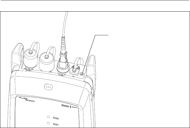
BV198.EPS
Figure 56. How to Turn on the Remote’s Optical Source
Step 2: Measure the Loss of the Test Reference
Cord You Will Add
WCaution
If you disconnected the test reference cord from
the output of the tester, you must set the
reference again to make sure your measurements
are reliable.
2-1 On the SET REFERENCE screen, when the reference procedure
is completed, tap NEXT.
2-2 Disconnect the test reference cord from the INPUT port on the
tester, then use a test reference cord and adapter to make the
connections to verify the TRCs, as shown on the screen and in
Figure 55.
-continued-
Hold down the button for 3
seconds to turn on the
multimode source.
CFP-QUAD modules: To turn on
the singlemode source, press
the button again.

Chapter 6: Certify Fiber Cabling
Autotest in Far End Source Mode
143
2-3 Tap TRC VERIFICATION. The tester measures and saves the loss
of the test reference cord you added. The ID for this result
starts with “TRC”, shows the date and time of the test, and has
an for the test result.
The tester shows a warning if the loss of a TRC is more than
these limits:
Maximum loss for multimode TRCs: 0.15 dB
Maximum loss for singlemode TRCs: 0.25 dB
If the tester shows a warning, clean and inspect the
connectors on the TRC, make sure the cords are straight as
shown in Figure 55, then do the TRC verification again.
Step 3: Do an Autotest in Far End Source Mode
WCaution
If you disconnected the test reference cord from
the output of the tester, you must set the
reference again to make sure your measurements
are reliable.
3-1 On the SET REFERENCE, when the set reference or TRC
verification procedure is completed, tap NEXT to see how to
connect to the fiber under test.
3-2 Clean and inspect the all connectors.
3-3 Make the connections to do the test on the fiber, as shown on
the screen and in Figure 55, then tap HOME.
3-4 If necessary, select End 1 or End 2: On the home screen, tap the
Next ID: panel, then tap the End 1/End 2 control to select an
end.
3-5 Tap TEST on the main tester or press on the main or
remote tester.

Versiv 2 Cabling Certification Product Family
Users Manual
144
3-6 If the CHECK FIBER CONNECTIONS screen shows an open
fiber:
Make sure that all connections are good and no fibers
have damage. Use the VFL to make sure the fiber under
test has continuity.
If you are connected to a fiber at a patch panel, and you
are not sure you are connected to the correct fiber,
connect the main tester’s INPUT fiber to different
connections until the test continues.
3-7 If Auto Save is on, the tester uses the next ID to save the
results.
If Auto Save is off, the SAVE RESULT screen shows the next
ID available. You can change the ID if necessary.
Note
To put End 1/End 2 results together in the same
record, use LinkWare software to merge the
results.
Autotest Results for Far End Source Mode
Figure 57 shows an example of Autotest results for Far End Source
mode.
Note
The Autotest in Far End Source mode does not
show a PASS/FAIL result, limit, or margin if the
selected test limit uses fiber length to calculate
loss. An example of such a limit is the TIA-568C
Fiber Backbone limit. The tester does not measure
length in Far End Source mode.
Chapter 6: Certify Fiber Cabling
Autotest in Far End Source Mode
145
GPU120.EPS
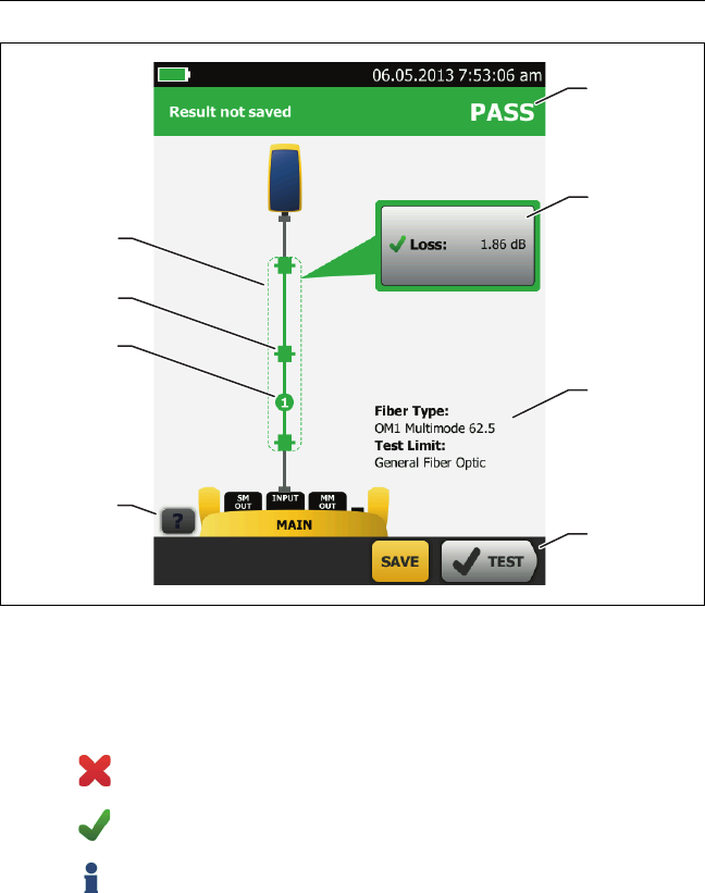
Figure 57. Result for Far End Source Mode
The overall result for the Autotest.
The loss and length measurements for the fiber:
The result exceeds the limit.
The result is within the limit.
The selected test limit does not have a limit for the test.
To see the results, limit, and margins for the fiber, tap the
window.
The settings the tester used for the test.
D
G
E
F
A
B
C
H

Versiv 2 Cabling Certification Product Family
Users Manual
146
The dashed lines are around the connectors and fiber that are
included in the loss and length results. Gray connectors and
fibers are not included because you used them to set the
reference.
Connector icons show the number you entered for the TOTAL
CONNECTIONS setting on the No. of Connectors/Splices
screen (Figure 46 on page 117). For Figure 57, the TOTAL
CONNECTIONS setting is 1.
The round icon shows the number of splices entered for the
SPLICES setting on the No. of Connectors/Splices screen.
To see help for the screen, tap .
When more than one button shows at the bottom of the screen,
the tester highlights one in yellow to recommend which one to
tap. See “Buttons to Do Tests and Save Results” on page 17.
Bi-Directional Tests
Do bi-directional tests when they are required by the
manufacturer or by your customer.
The tester can automatically do bi-directional tests in Smart
Remote and Loopback modes. To get bi-directional results in Far
End Source mode, do a test from each end of the fiber.
In Smart Remote mode, the tester saves bi-directional results in
two records. Each record contains the results for one fiber for
both directions.
To do a bi-directional test
1On the home screen, tap the test setup panel, make sure the
correct test is selected on the CHANGE TEST screen, then tap
EDIT.
2On the TEST SETUP screen, in the Bi-Directional panel, tap the
control to make it show On, then tap SAVE.
3Do an Autotest.
-continued-

Chapter 6: Certify Fiber Cabling
Bi-Directional Tests
147
4Halfway through the test, the tester tells you to switch the
input and output fibers.
WCaution
Switch the connections at both ends of the patch
panel or fiber under test, not at the tester's and
remote’s ports. If you disconnect a test reference
cord from an output port on the tester or remote,
the reference value will be unreliable.
Note
The directions Main>Remote (main to remote)
and Remote>Main (remote to main) in the bi-
directional results are only the directions of the
optical signals for the second half of the test. If a
fiber fails, the direction does not tell you the
location of the problem.
5If Auto Save is on and the tester is in Smart Remote mode, the
tester uses the next two IDs to save the results for the two
fibers.
If Auto Save is off, and you tap SAVE or FIX LATER, the SAVE
RESULT screen shows the next two IDs available. You can
change the IDs if necessary.

Versiv 2 Cabling Certification Product Family
Users Manual
148
149
Chapter 7: Use the OTDR
WWarningX*
Before you use the tester, read the safety
information that starts on page 5.
Overview of Features
The OptiFiber® Pro Optical Time Domain Reflectometer (OTDR)
module attaches to a Versiv™ 2 main unit to make a rugged,
hand-held tester that lets you locate, identify, and measure
reflective and loss events in multimode and singlemode fibers.
Typical maximum test ranges are 35 km maximum at 1300 nm for
multimode fiber and 130 km maximum at 1550 nm for
singlemode fiber. The tester includes these features:
Automatic analysis of OTDR traces and events helps you
identify and locate faults on multimode (850 nm and
1300 nm; 50 μm and 62.5 μm) and singlemode (1310 nm and
1550 nm) fiber.
Shows OTDR results as an intuitive map of events, a table of
events, and an OTDR trace.
Automatic bi-directional averaging gives you more accurate
loss measurements than measurements made in one
direction.
Gives a PASS or FAIL result based on a test limit that you
specify.
“Document Only” test limit is available if PASS/FAIL results are
not necessary.
Touchscreen lets you quickly navigate through different views
of the results and see more information about events.
SmartLoop™ test: One test gives you OTDR results for both
fibers in a link.

Versiv 2 Cabling Certification Product Family
Users Manual
150
DataCenter OTDR™ test gives optimal performance when you
do tests on fiber installations that have short links, many
connections, and possibly large reflections.
FaultMap™ test lets you make maps of your cable plant, see
patch cords as short as 0.5 m, and see events that have poor
reflectance.
Visual fault locator helps you verify the continuity of fibers
and locate faults in fibers and connectors.
Optional FiberInspector™ video probe lets you inspect fiber
endfaces and save the images in test reports.
Saves approximately 2000 OTDR tests on fiber links with an
average length of 2 km, and up to 5000 tests for lengths less
than 2 km.
Connectors, Keys, and LEDs
See Figure 58.
LCD display with touchscreen.
Singlemode OTDR port with interchangeable SC adapter and
protective cap. The LED in front of the port turns on when the
port emits an optical signal.
Multimode OTDR port with interchangeable SC adapter and
protective cap. The LED in front of the port turns on when the
port emits an optical signal.
Visual fault locator port and protective cap. The LED in front
of the port turns on when the port emits an optical signal.
WWarning*
Do not look directly into optical connectors. Some
sources emit invisible radiation that can cause
permanent damage your eyes.
Button that controls the VFL.
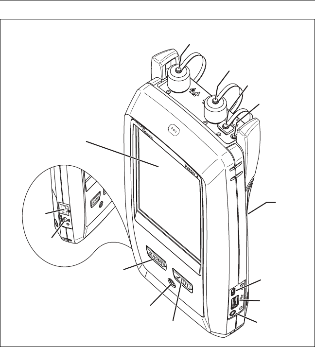
G
E
F
W*
C
B
D
M
L
A
H
N
K
I
J
Chapter 7: Use the OTDR
Connectors, Keys, and LEDs
151
BV06.EPS
Figure 58. Connectors, Keys, and LEDs
(OptiFiber Pro Quad OTDR shown)
Micro-AB USB port: This USB port lets you connect the tester
to a PC so you can upload test results to the PC and install
software updates in the tester.
Type A USB port: This USB host port lets you save test results
on a USB flash drive and connect the FI-1000 video probe to the
tester.
Versiv 2 Cabling Certification Product Family
Users Manual
152
Headset jack.
: Starts a test. To start a test, you can also tap TEST on
the display.
: Power key.
: Press to go to the home screen.
Connector for the AC adapter. The LED is red when the
battery charges, and green when the battery is fully charged.
The LED is yellow if the battery will not charge. See “Charge
the Battery” on page 11.
RJ45 connector: Lets you connect to a network for access to
Fluke Networks cloud services.
Decal with laser
safety information:
How to Remove and Install the Connector
Adapters
You can change the connector adapters on the OTDR ports of the
modules to connect to SC, ST, LC, and FC fiber connectors. You
can remove the adapter also to clean the fiber endface in the
port. See Figure 59.
Chapter 7: Use the OTDR
How to Remove and Install the Connector Adapters
153
GPU165.EPS
Figure 59. How to Remove and Install the Connector Adapters
LC SC
Keep extra adapters in
the containers provided.
WCaution
Turn only the collar on the adapter.
Do not use tools to remove or install
the adapters.
Key
Slot
Put the key into the slot
before you turn the collar
on the adapter.
Versiv 2 Cabling Certification Product Family
Users Manual
154
The OptiFiber Pro Home Screen
The home screen (Figure 60) shows important test settings. Before
you do a test, make sure these settings are correct.
GPU02.EPS
Figure 60. The Home Screen
PROJECT: The project contains the settings for a job and helps
you monitor the status of a job. When you save test results, the
tester puts them in the project. Tap the PROJECT panel to edit
the project settings, select a different project, or make a new
project.
L
FG H
A
D
B
E
J
I
C
K

Chapter 7: Use the OTDR
The OptiFiber Pro Home Screen
155
Shows a summary of the test results in the project:
: The number of tests that passed.
: The number of tests that failed.
The test setup panel shows the settings the tester will use
when you tap TEST or press .
To change these settings, tap the panel, select the test on the
CHANGE TEST screen, tap EDIT, select different settings on the
TEST SETUP screen, then tap SAVE.
Note
You can set up tests for any module that the
tester can use, even when no module is attached.
Next ID: The Next ID panel shows the ID that the tester gives
to the next test results you save.
Tap Next ID to do these tasks:
Enter an ID, select a different ID in the ID set, select a
different set of IDs, or make a new set. The tester adds the
IDs and ID sets you make to the project that shows on the
home screen.
Turn Auto Save on or off.
Select End 1 or End 2 for OTDR and FiberInspector tests.
Enter a name for End 1 and End 2.
Operator: The name of the person who does the job. You can
enter a maximum of 20 operator names. For each operator you
can also enter the email address that the operator will use as an
ID to sign in to LinkWare Live.
TOOLS: The TOOLS menu lets you set up the compensation
function for the launch/tail cords, use tools such as the real-
time trace and the FiberInspector test, see the status of the
tester, and set user preferences such as the language and the
display brightness.

Versiv 2 Cabling Certification Product Family
Users Manual
156
RESULTS: Tap RESULTS to see and manage the results that are
saved in the tester.
SYNC: Tap SYNC to sync projects with LinkWare Live.
TEST: Tap TEST to do the test shown in the test setup
panel.The percentage of the tests in the project that are
completed. The tester uses the number of available IDs and
the tests you selected on the CABLE ID SETUP screen to
calculate this percentage. See Figure 89 on page 223. %
Tested does not show if your project contains only a Next ID
list. See “About Next ID Sets” on page 225 for more
information about the Next ID list.
The type of module attached to the tester. If no module is
attached, this screen shows HOME.
The asset management icon shows when the owner of a
LinkWare Live account has enabled the asset management
service on the tester. See “About the Asset Management Service”
on page 238.
Settings for OTDR Tests
Table 7 gives descriptions of the settings for OTDR tests. To set up
a project, which includes the settings in Table 7, cable IDs, and
operator names, see Chapter 11.
To set up an OTDR test
1On the home screen, tap the test setup panel.
2On the CHANGE TEST screen, select an OTDR test to change,
then tap EDIT.
Or to set up a new OTDR test, tap NEW TEST then tap a Test
Type.
3On the TEST SETUP screen, tap the panels to change settings
for the test. See Table 7.
4On the TEST SETUP screen, tap SAVE when your test setup is
completed.

Chapter 7: Use the OTDR
Settings for OTDR Tests
157
5On the CHANGE TEST screen, make sure the button next to
the test is selected, then tap USE SELECTED.
Table 7. Settings for OTDR Tests
Module Select the OTDR module you will use.
To select a different module, tap the Module panel on the
TEST SETUP screen, then tap a module.
Test Type When you turn on the tester, the Test Type shows the test
that was last selected.
Auto OTDR: The tester automatically selects settings that
give you the best view of the events on the cabling. This
mode is the easiest to use and is the best choice for most
applications. To see the settings the tester used for an
Auto OTDR test, tap SETTINGS on the trace screen.
Note
Some unusual faults can cause the Auto OTDR
test to show an unsatisfactory trace. If this occurs,
use the Manual OTDR test to get a better trace.
Manual OTDR: This mode lets you select settings to control
the qualities of the trace. See the Technical Reference
Handbook.
DataCenter OTDR: This test is optimized for fiber
installations that have short links, many connections, and
the possibility of large reflections.
Notes
By default, the DataCenter OTDR test uses 850 nm
for multimode fiber and 1310 nm for singlemode
fiber. These are the wavelengths typically used in
data centers. You can select other wavelengths if
necessary.
You must use launch compensation when you do
a DataCenter OTDR test.
(continued)

Versiv 2 Cabling Certification Product Family
Users Manual
158
Test Type
(cont.)
FaultMap: The FaultMap test can show connections that
do not show on the OTDR EventMap and connections that
are poor because they have high reflectance. See “The
FaultMap Test” on page 178.
SmartLoop OTDR (Auto) and SmartLoop OTDR (Manual):
The SmartLoop test lets you connect the far ends of the
two fibers in a link so that one OTDR test gives you results
for both fibers. The Auto and Manual settings operate the
same as for the OTDR test. See “The SmartLoop Test” on
page 184.
Manual OTDR
Settings
This item shows only if you select Manual OTDR or
SmartLoop OTDR (Manual) for the Test Type. Manual
OTDR mode lets you select settings to control the qualities
of the trace. See the Technical Reference Handbook.
Bi-Directional This setting shows only if you select SmartLoop OTDR
(Auto) or SmartLoop OTDR (Manual) for the Test Type.
Off: The tester does the SmartLoop test in only one
direction.
On: The tester does the SmartLoop test in both directions
and automatically calculates bi-directional averages of
loss. See “Bi-Directional SmartLoop Tests” on page 191.
Launch
Compensation
Tap the control to turn the launch compensation function
on or off. See“About Launch and Tail Cords” on page 160.
Wavelength Select the wavelengths you want to use. You can do tests
at one or all of the wavelengths supported by the module
you selected.
Fiber Type Select a fiber type that is correct for the type you will test.
To see a different group of fiber types, tap MORE, then
tap a group.
Note
Select a fiber type before you select a test limit
and wavelengths. The tester shows only the test
limits and wavelengths that are applicable to the
selected fiber type.
Table 7. Settings for OTDR Tests (continued)

Chapter 7: Use the OTDR
Settings for OTDR Tests
159
Fiber Type
Settings
IR: The tester uses the index of refraction to calculate the
optical length of the fiber. Each fiber type includes the
value specified by the manufacturer. To use a different IR,
make a custom fiber type. See the Technical Reference
Handbook.
Backscatter: Backscatter is the backscatter coefficient. The
tester uses this value to calculate the reflectance of events
for OTDR tests and the overall ORL for the link. Each fiber
type includes the value specified by the manufacturer. To
use a different backscatter value, make a custom fiber
type. See the Technical Reference Handbook.
Test Limit Select the correct test limit for the job. Generic limits, such
as General Fiber and Document Only, let you do tests
when no industry-standard limit is applicable and you do
not want to make a custom limit. These limits are in the
Miscellaneous group. To see a different group of limits,
tap MORE, then tap the name of a group.
Some test limits use the measured length of the fiber to
calculate a limit for loss.
Test Limit
Settings
This item shows only if the selected test limit calculates a
loss limit for each link. For such limits, enter the number of
connectors and splices in the link. See the Technical
Reference Handbook.
Table 7. Settings for OTDR Tests (continued)

Versiv 2 Cabling Certification Product Family
Users Manual
160
About Launch and Tail Cords
Launch and tail cords let the tester measure the loss and
reflectance of the first and last connectors in the cabling and also
include them in the measurement of overall loss. Without launch
and tail cords, no backscatter is available before the first
connector nor after the last. To measure the properties of a
connector, the tester must measure the backscatter before and
after the connector.
Fluke Networks recommends that you use launch and tail cords.
You should also use the launch/tail cord compensation function
to remove the lengths of these fibers from the OTDR
measurements.
If you select a test limit that requires you to use launch and tail
cords, the tester shows a warning message when you try to do an
OTDR test without launch and tail cords.
WCaution
For tests on cabling that has angled physical contact
(APC) connectors, use only launch/tail cords that
have APC connectors at the ends connected to the
cabling. Other connector types cause large
reflections that can cause unreliable test results.
Notes
Do not use hybrid patch cords to connect the
launch or tail cords to the cabling under test. Use
launch and tail cords with the correct connectors
to connect directly to the cabling under test. This
gives the best measurement of the first and last
connectors in the link. Launch and tail cords with
different types of connectors are available from
Fluke Networks.
Launch + Tail compensation usually gives the most
accurate measurements.
The style of the case for your launch/tail cords can
be different from the cords shown in this manual.

Chapter 7: Use the OTDR
About Launch and Tail Cords
161
How to set up the launch compensation function
1Select launch and tail cords that have the same type of fiber
as the fiber you will test.
2On the home screen, tap the test setup panel. On the
CHANGE TEST screen, select an OTDR test to change, then tap
EDIT. Or to set up a new OTDR test, tap NEW TEST then tap
Auto OTDR, Manual OTDR, or DataCenter OTDR.
3On the TEST SETUP screen, tap the Launch Compensation
control to set it to On.
4On the TEST SETUP screen, make sure the Fiber Type is correct.
Change it if necessary.
5On the TEST SETUP screen, tap SAVE.
6On the home screen, tap the TOOLS icon, then tap Set Launch
Compensation.
7On the SET LAUNCH METHOD screen tap the type of
compensation you want to do.
8Clean and inspect the OTDR port and the launch/tail cord
connectors.
9Make the connections for the type of compensation you
selected, as shown on the SET LAUNCH METHOD screen.
10 Tap SET.
11 When the SET LAUNCH COMP screen shows, select the event
or events that are the end of the launch cord and the start of
the tail cord (if you used a tail cord).
12 Tap SAVE.
Figure 71 shows an example of an OTDR trace with launch and
tail markers enabled.
Note
If you change the launch or tail cord, do the
compensation procedure again.
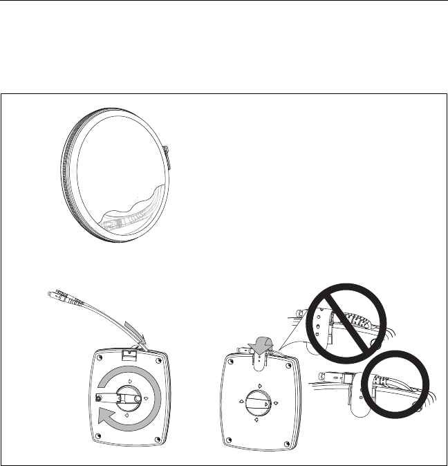
Versiv 2 Cabling Certification Product Family
Users Manual
162
How to Prevent Damage to the Launch Cord Connectors
When you do not use a launch cord, keep the connectors
attached to the case or inside the case. See Figure 61.
GPU44.EPS
Figure 61. How to Prevent Damage to the Launch Cord Connectors
How to Hang the Launch Cords
The optional TPAK magnet and strap let you hang the launch
cords from metal surfaces (Figure 62).
WCaution
Do not make tight bends
in the fibers.
Cords with a
mechanical reel
Cords in a
zippered case
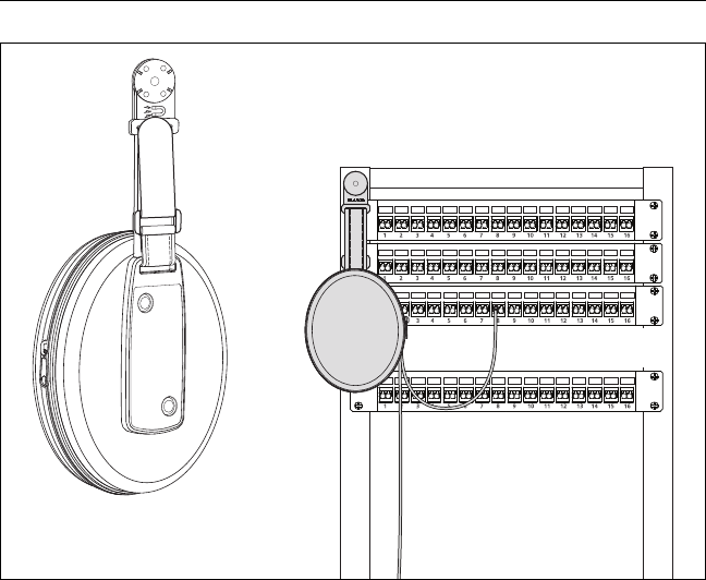
Chapter 7: Use the OTDR
OTDR Port Connection Quality
163
GPU191.EPS
Figure 62. How to Use the Optional TPAK Magnetic Hanger
OTDR Port Connection Quality
When you do an OTDR test, the test shows the quality of the
OTDR port connection (Figure 63). If a test takes more than
approximately 3 seconds, the PROGRESS screen also shows a
preview of the OTDR trace. The trace is black for one wavelength
and blue for the other wavelength.
If the gauge is not in the Good range
Clean the OTDR port and the fiber connector. Use a video
probe to inspect the endfaces in the port and fiber connector
for scratches and other damage. If an endface on the tester
shows damage, contact Fluke Networks for service
information.
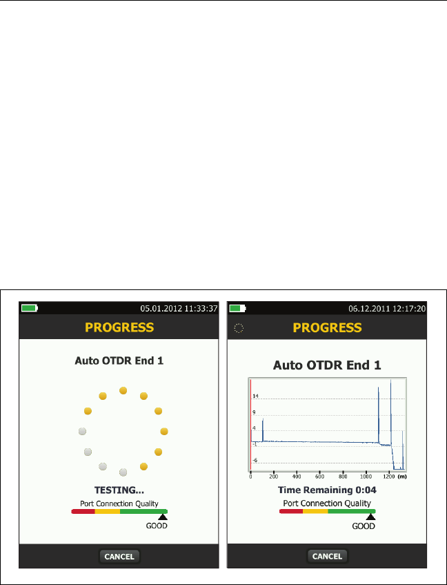
Versiv 2 Cabling Certification Product Family
Users Manual
164
If the gauge stays outside the Good range, remove the
adapter from the module and inspect the adapter for
damage. Make sure that the white plastic ring inside the
center tube shows no damage.
A poor OTDR connection increases the dead zone at the
connector. The dead zone can hide faults that are near the OTDR
connector.
A poor connection also decreases the strength of the signal from
the OTDR. The weaker signal causes more noise on the trace,
which can cause the OTDR to miss events. It also decreases the
dynamic range.
When the test is completed, the quality gauge shows in the
details for the OTDR Port event on the EventMap screens. The
tester includes the gauge with the test results you save.
GPU17.EPS
Figure 63. The OTDR Port Connection Quality Gauge and Progress Screen
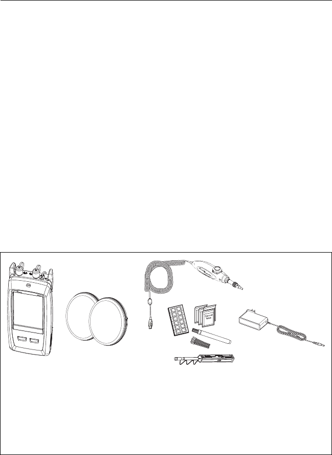
Chapter 7: Use the OTDR
How to Do an OTDR Test
165
How to Do an OTDR Test
Figure 64 shows the equipment for OTDR tests.
To do an OTDR test
1Make sure that the home screen shows the correct settings for
the job. If it is not necessary to use specific settings, set the
test type to Auto OTDR to make sure the results show all of
the events on the fiber.
2Clean and inspect the connectors on the launch and tail cords
and the fiber to be tested.
3Connect the tester to the link as shown in Figure 65, 66, or 67.
4Tap TEST or press .
Note
The tester shows a warning if there is an optical
signal on the fiber.
Figure 64. Equipment for OTDR Tests
BV31.EPS
Versiv 2 unit with OTDR module
installed
Launch and tail cords (match the
fiber to be tested)
FI-1000 video probe with USB
connector
Fiber cleaning supplies
AC adapter (optional)
AB
C
E
D
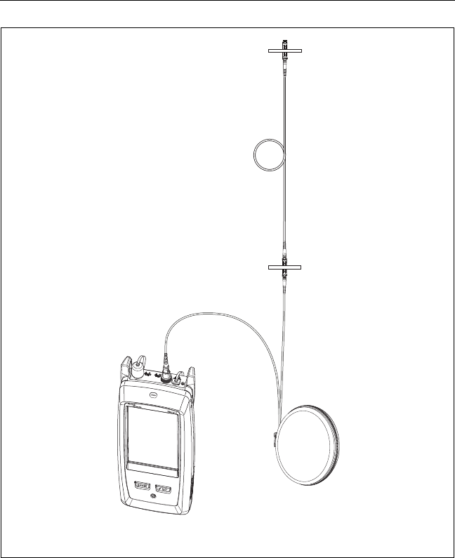
Versiv 2 Cabling Certification Product Family
Users Manual
166
BV03.EPS
Figure 65. OTDR Connected with a Launch Cord
Launch cord
Fiber link
Versiv 2 unit with
OTDR module