Fluke Electronics VERSIV2 CableAnalyzer User Manual Verisiv Part 3
Fluke Electronics CableAnalyzer Verisiv Part 3
Contents
- 1. User Manual DSX 302
- 2. User Manual Statement
- 3. User Manual Verisiv Part 1
- 4. User Manual Verisiv Part 2
- 5. User Manual Verisiv Part 3
User Manual Verisiv Part 3
Chapter 7: Use the OTDR
How to Do an OTDR Test
167
BV04.EPS
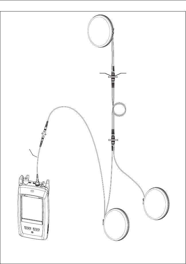
Figure 66. OTDR Connected with Launch and Tail Cords
Launch cord
Tail cord
Fiber link
Versiv 2 unit with
OTDR module
Versiv 2 Cabling Certification Product Family
Users Manual
168
BV05.EPS
Figure 67. OTDR Connected to a Spool of Fiber
Mechanical
splice
Versiv 2 unit with
OTDR module
Spool of fiber

Chapter 7: Use the OTDR
OTDR Results
169
OTDR Results
Notes
The tester shows measurements with “>” or “<“
when the actual value is possibly more or less than
the value shown. For example, this can occur for
hidden events or for measurements that are out
of the range of the tester.
When a test is completed, the type of screen the
tester shows first (EventMap, TABLE, or TRACE) is
the type you looked at last.
EventMap
Notes
The EventMap combines the results for all
wavelengths used for the test. If an event on the
EventMap does not show on the event table or
OTDR trace, change the wavelength on the OTDR
screen.
The EventMap does not show ghosts.
See Figures 68 and 69.
Versiv 2 Cabling Certification Product Family
Users Manual
170
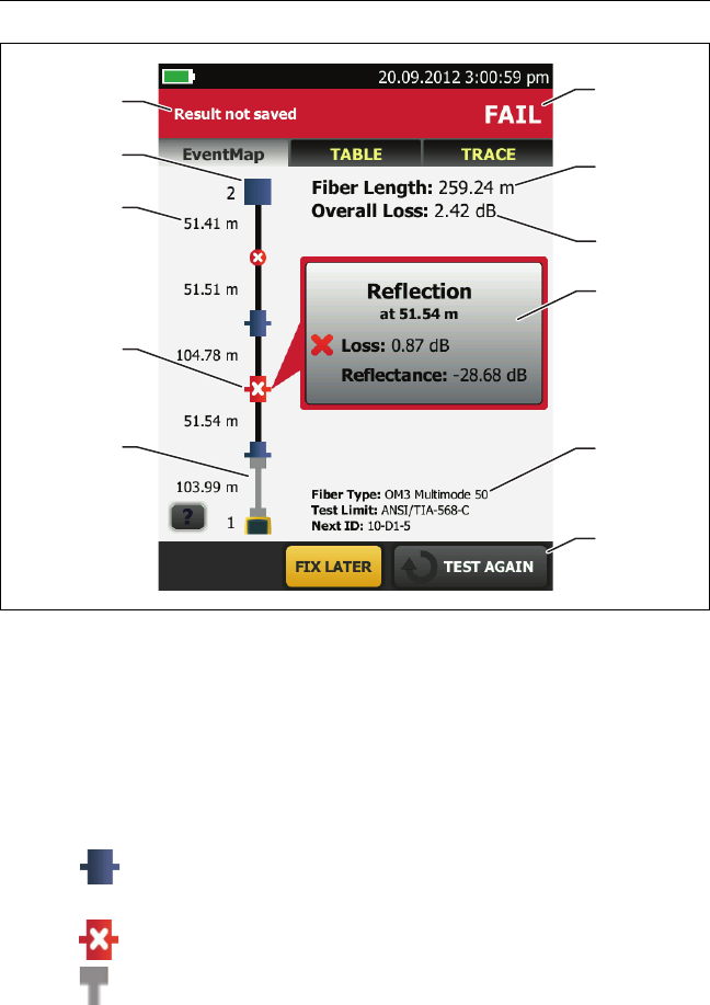
GPU11.EPS
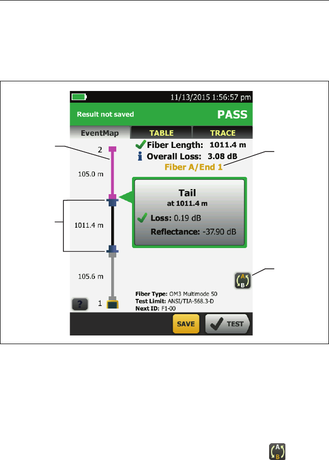
Figure 68. EventMap Example 1
The ID for the results. If Auto Save is off, Result not saved
shows.
The end of the fiber.
The length of the fiber segment between two events.
A reflective event:
: A reflective event, which is usually a connector.
Measurements for the event are all within the test limits.
: One or more measurements for the event exceeds the limit.
: Launch and tail cords and their connectors show in gray.
The map shows these if Launch Compensation is on and the
cords are connected.
A
B
D
C
K
H
J
G
F
E
I

Chapter 7: Use the OTDR
OTDR Results
171
: The arrow icon shows when there are more events that do
not show on the screen. To see the events, tap the icon or scroll
the map.
When more than one button shows at the bottom of the
screen, the tester highlights one in yellow to recommend
which one to tap. See “Buttons to Do Tests and Save Results”
on page 17.
The fiber type and test limit the tester used for the test, and
the ID the tester will use for the next results that you save.
When a test is completed, the window shows information for
the event that has the worst measurement. The information
windows show the worst results of the wavelengths used for
the test.
If the window border is green, the measurements for the event
do not exceed the limits.
If the window border is red, a measurement exceeds the limits.
If the window border is blue, the tester does not give a pass or
fail result to the event because it cannot do a full analysis of the
event. This occurs for OTDR Port, Hidden, and End events. This
occurs for all events if you use the Document Only test limit
because Document Only does not have values for limits.
When you use a test limit that has a reflectance limit, Hidden
events show a fail status if their reflectance exceeds the limit.
: The measurement exceeds the limit.
: The measurement is within the limit.
To see details for the event, tap the window.
To see information for another event, tap another icon on the
map.
Note
Events before the launch cord connector and after
the tail cord connector do not have a pass or fail
status.

Versiv 2 Cabling Certification Product Family
Users Manual
172
Overall Loss: The loss of the cabling. This does not include the
OTDR connection and the loss of the last event. If Launch
Compensation is on, the overall loss includes the launch and
tail connectors, but not the launch and tail fibers.
If you did the test at two wavelengths, the tester shows the
highest loss of the two wavelengths.
N/A shows for the Overall Loss if the tester cannot measure the
loss. This can occur when events are too close together or when
there is a large reflective event near the end of the fiber.
Fiber Length: The length of the fiber. The units show in
meters (m) or feet (ft). If Launch Compensation is on, the
length does not include the length of the launch and tail
cords.
PASS/FAIL: The overall result for the fiber.
PASS: All measurements are within the test limits.
FAIL: One or more measurements exceed the limit.
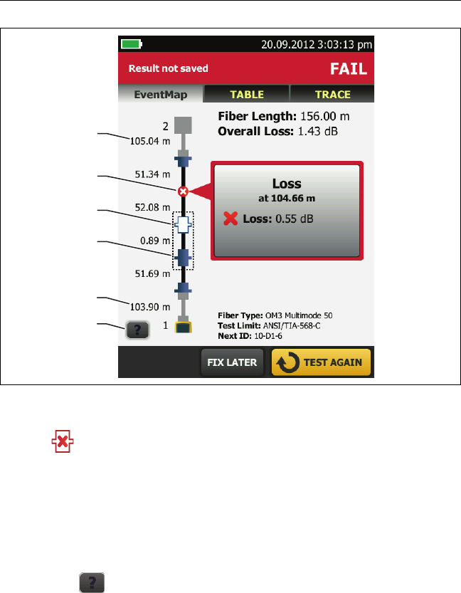
Refer to Figure 69:
Length of the tail cord (top) and launch cord (bottom).
A loss event, such as a splice or bend:
: Measurements for the event are all within the test limits.
: One or more measurements for the event exceeds the limit.
: The event is hidden by a previous event.
The map shows a dotted line around hidden events and the
event that causes them to be hidden. The tester combines the
loss of all the events that are in the dotted line. To see the
combined loss, tap the event that causes the hidden event ().
The tester does not show loss measurements for hidden events.
Chapter 7: Use the OTDR
OTDR Results
173
GPU22.EPS
Figure 69. EventMap Example 2
: The event is hidden by a previous event. The reflectance of
the event exceeds the limit. This icon shows only when the test
limit has a limit for reflectance.
The cause of the hidden event. In this example, the cause is a
connector on a short patch cord. The loss of the second
connector is hidden in the attenuation dead zone of the first
connector.
Tap to see information about the selected event.
A
C
A
B
D
E

Versiv 2 Cabling Certification Product Family
Users Manual
174
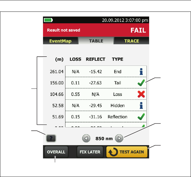
Event Table
The event table shows a list of the events on the fiber. To see the
event table, tap TABLE on the OTDR results screen. Figure 70
shows an example of an event table.
To see details for an event, tap the event in the table. Scroll the
table if necessary to see all the events.
(ft) or (m): The distance to the event
LOSS: The loss of the event.
REFLECT: The reflectance of the event.
TYPE: The event type.
Note
The OTDR Port and End events always show N/A
for loss because backscatter measurements are
not available on both sides of those events.
Tap to see help for this screen.
OVERALL: Tap this button to see overall measurements of
length, loss, and optical return loss for the fiber.
When more than one button shows at the bottom of the
screen, the tester highlights one in yellow to recommend
which one to tap. See “Buttons to Do Tests and Save Results”
on page 17.
If the tester made measurements at two wavelengths, tap the
arrow buttons to see results for the other wavelength.
Possibly, some events show only at one wavelength.
: The measurement is within the limit.
: The measurement exceeds the limit.
: The tester does not give a pass or fail result to the event. This
occurs for OTDR Port, Hidden, and End events. This occurs for all
events if you use the Document Only test limit because
Document Only does not have values for limits.
Chapter 7: Use the OTDR
OTDR Results
175
GPU12.EPS
Figure 70. Event Table
When you use a test limit that has a reflectance limit, Hidden
events show a FAIL status if their reflectance exceeds the limit.
To see details for an event, such as limits for measurements and
the SEGMENT ATTENUATION coefficient, tap the event in the
table.
A
B
E
F
D
C
Versiv 2 Cabling Certification Product Family
Users Manual
176
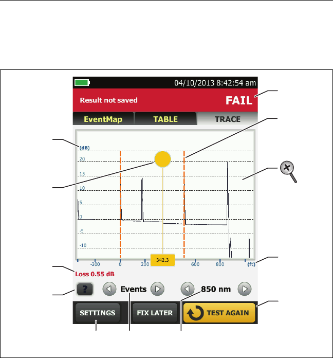
OTDR Trace
To see the OTDR trace, tap TRACE on the OTDR results screen.
Figure 71 shows an example of an OTDR trace.
GPU14.EPS
Figure 71. OTDR Trace
The decibel scale shows the level of backscatter. The tester sets
the backscatter level at the start of the trace to approximately
0 dB.
The measurement cursor. To measure loss and distance, tap
the yellow circle so that MARK shows, drag the cursor to the
start of the measurement, tap MARK, then drag the cursor to
the end of the measurement.
B
C
D
A
G
I
K
FE
H
J
Chapter 7: Use the OTDR
OTDR Results
177
When the cursor is on an event, this area shows the event
type. The text is green if the event passed, red if the event
failed, or black is there is no limit for measurements. The
event type does not show after you tap MARK to use the
measurement cursor.
Tap to see help for this screen.
Tap SETTINGS to see the settings the tester used for the OTDR
test. The tester saves the settings with the result.
Tap or to move the cursor to another event.
The wavelength the tester used for the test. If the tester used
more than one wavelength, tap or to see the other
wavelength. Possibly, some events show only at one
wavelength. You can select wavelengths on the TEST SETUP
screen.
When more than one button shows at the bottom of the
screen, the tester highlights one in yellow to recommend
which one to tap. See “Buttons to Do Tests and Save Results”
on page 17.
The distance scale shows the distance along the fiber.
Markers for the end of the launch cord and the beginning of
the tail cord are orange, dashed lines.
PASS: All measurements were within the limits.
FAIL: One or more measurements exceeded its limit.
To zoom in and out, use the pinch, reverse-pinch, and double-
tap gestures on the touchscreen. You can also use the zoom
controls to change the magnification on the distance and
decibels scales independently. See Figure 3 on page 16.

Versiv 2 Cabling Certification Product Family
Users Manual
178
The FaultMap Test
The FaultMap test helps you record the connections in a fiber link
and identify bad connections. It can show short patch cords and
find connections that have high reflectance. The FaultMap test
gives you these results:
Shows a map of the connectors in the link that possibly do not
show on the OTDR EventMap. The map includes connectors
that are hidden in the dead zones made by previous events.
The FaultMap test shows patch cords as short as 0.5 m for
lengths < 2 km.
Shows connections that are poor because they have high
reflectance (> -35 dB).
Reflective events that are apparently not connectors do not show
on the FaultMap diagram. Loss events are also not shown.
The FaultMap test finds events that have a reflectance larger than
approximately -50 dB on multimode fiber and -60 dB on
singlemode fiber. (More negative values mean less reflectance
and a better connection. For example, a connector with a
reflectance of -40 dB is better than one with -35 dB.)
Notes
Since the FaultMap test finds only reflections, do
not use it to look for fusion splices or angled
physical contact (APC) connectors.
FaultMap results do not include a PASS/FAIL status.
The results are only for your documentation of the
link.
FaultMap tests on singlemode fiber usually take
more time than OTDR tests. The test uses very
narrow pulses on singlemode fiber to make the
smallest event dead zones possible, and does
more analysis on the reflections in the link.

Chapter 7: Use the OTDR
The FaultMap Test
179
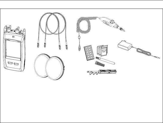
How to Do the FaultMap Test
Notes
The FaultMap test does not use the launch
compensation settings.
The FaultMap test uses the wavelength that gives
the best results.
Figure 72 shows the equipment for the FaultMap test.
1Clean and inspect the connectors on the launch and tail cords
or patch cords and the link to be tested.
2Connect the launch cord to the OTDR port and the link to be
tested, as shown in Figure 73. Connect a tail cord to the far
end of the link if necessary.
Or, you can use a patch cord that is 1 m long at minimum to
connect the tester to the link. To see results for the far-end
connector, connect a tail cord or patch cord (>1 m) to the far end
of the link.
3On the home screen, tap the test setup panel.
4On the CHANGE TEST screen, tap the button next to the
FaultMap test, then tap USE SELECTED. If a FaultMap test is
not available, tap NEW TEST to add one to the project.
5Tap TEST or press .
Versiv 2 Cabling Certification Product Family
Users Manual
180
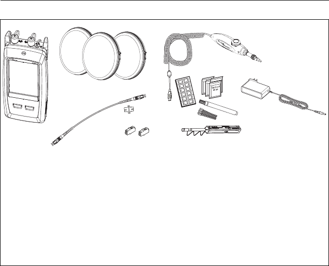
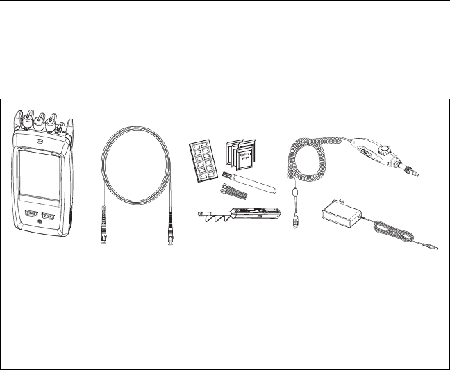
Figure 72. Equipment for FaultMap Tests
BV39.EPS
Versiv 2 unit with OTDR module
installed
Launch and tail cords or patch
cords (match the fiber to be
tested)
FI-1000 video probe with USB
connector
Fiber cleaning supplies
AC adapter (optional)
A
B
D
E
C
Chapter 7: Use the OTDR
The FaultMap Test
181
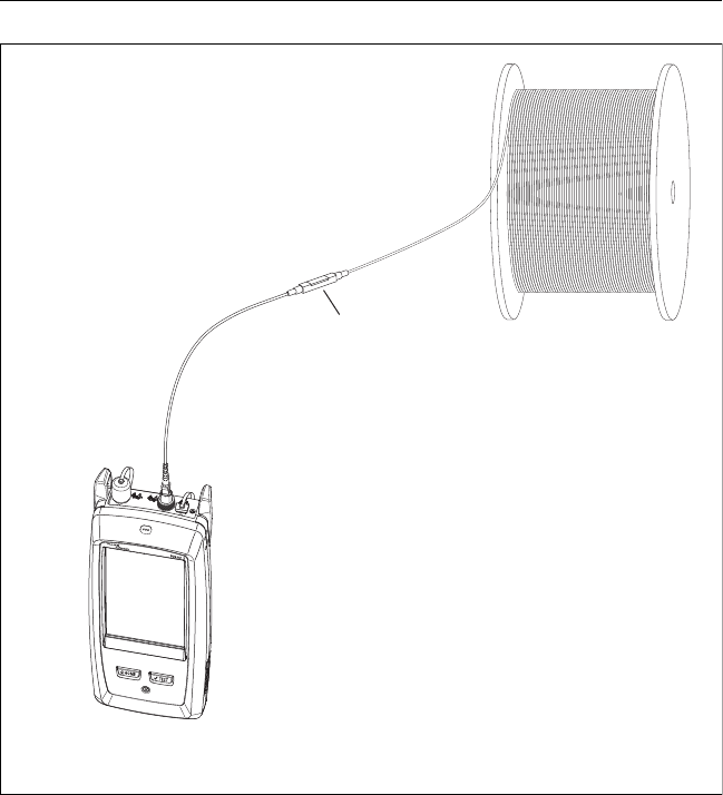
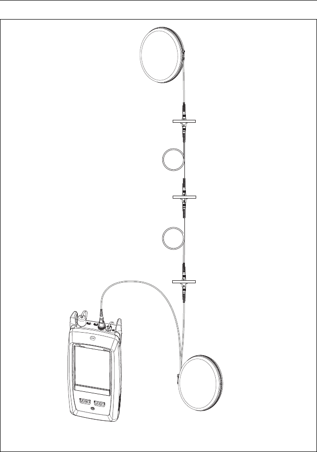
BV41.EPS
Figure 73. FaultMap Test Connections
Launch cord or
patch cord
(optional)
Tail cord or patch
cord (optional)
Versiv 2 unit with
OTDR module
Versiv 2 Cabling Certification Product Family
Users Manual
182
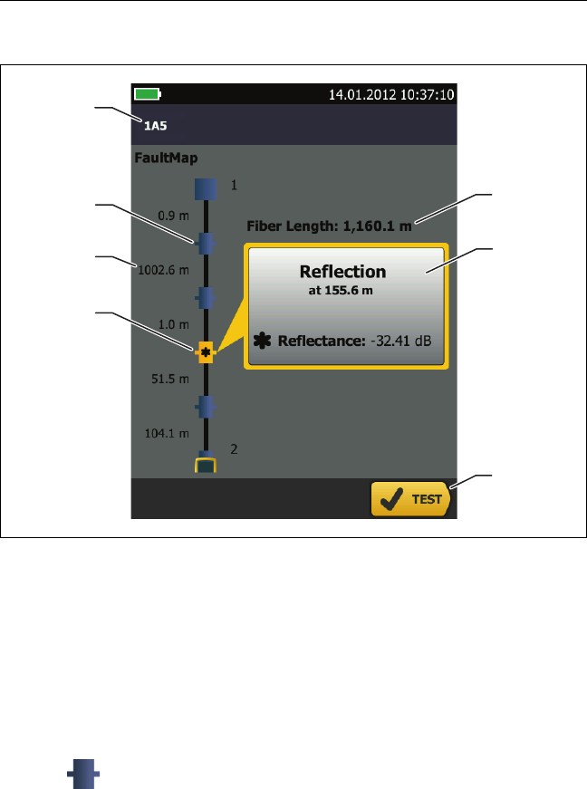
FaultMap Screen
GPU15.EPS
Figure 74. FaultMap Screen
Note
The FaultMap test does not use the launch
compensation settings. The results show the
launch and tail cords and their connectors in the
same colors as other cords and connectors.
The ID for the results. If Auto Save is off, Result not saved
shows.
: An event that has a reflectance smaller than -35 dB.
The length of the fiber segment between two events.
A
B
C
E
D
G
F

Chapter 7: Use the OTDR
The FaultMap Test
183
: An event that has a reflectance larger than -35 dB. It is
possibly a connector that is dirty, poorly polished, scratched,
cracked, misaligned, unseated, worn, or the wrong type.
: The arrow icon shows when there are more events that do
not show on the screen. To see the events, tap the icon or scroll
the screen.
When more than one button shows at the bottom of the
screen, the tester highlights one in yellow to recommend
which one to tap. See “Buttons to Do Tests and Save Results”
on page 17.
If the window is blue, the reflectance of the event is smaller
than -35 dB. If the window is orange, the reflectance is larger
than -35 dB.
To see the window for another event, tap another icon on the
fiber.
Fiber Length: The length of the fiber. This includes the lengths
of the launch and tail cords, if you used them.

Versiv 2 Cabling Certification Product Family
Users Manual
184
The SmartLoop Test
The SmartLoop test lets you connect the far ends of the two fibers
in a link and do one OTDR test to get separate results for each
fiber.
You use a launch cord to connect the fibers together at the far
end of the link. When you do the SmartLoop test, the tester uses
the launch compensation settings to remove the effects of the
loopback cord and its connectors.
The Auto and Manual settings for the SmartLoop test operate the
same as for the OTDR test. See Table 7 on page 157.
Figure 75 shows the equipment for the SmartLoop test.
Chapter 7: Use the OTDR
The SmartLoop Test
185
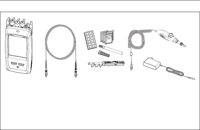
Figure 75. Equipment for SmartLoop Tests
BV169.EPS
Versiv 2 unit with OTDR module
installed
Three launch cords for launch,
tail, and loopback connections
(match the fiber to be tested)
Short patch cord (30 cm (12 in)
maximum) and adapter for bi-
directional tests
FI-1000 video probe with USB
connector
Fiber cleaning supplies
AC adapter (optional)
A
B
E
G
F
D
C

Versiv 2 Cabling Certification Product Family
Users Manual
186
How To Do an Auto SmartLoop Test
Set up the launch compensation function
1On the home screen, tap the test setup panel.
2On the CHANGE TEST screen, tap the button next to the Auto
SmartLoop test, then tap USE SELECTED.
If an Auto SmartLoop test is not available, tap NEW TEST to add
one to the project. Select settings as necessary on the TEST
SETUP screen. See “Settings for OTDR Tests” on page 157.
3Select three launch cords that have the same type of fiber as
the fiber you will test.
4On the home screen, tap the TOOLS icon, then tap Set Launch
Compensation.
5On the SET LAUNCH METHOD screen tap SmartLoop.
6Clean and inspect the OTDR port and connectors on the three
launch cords.
7Make the connections shown in Figure 76.
8Tap SET.
9When the SET LAUNCH COMP screen shows, make sure the
tester shows the correct distances for the end of the launch
cord and the start of the tail cord.
Note
If the fibers have APC connectors, the tester
possibly will not find the correct launch and tail
events. If this occurs, do the compensation again
and select Manual Entry to enter the lengths of
the cords manually.
10 Tap SAVE.
Chapter 7: Use the OTDR
The SmartLoop Test
187
BV170.EPS
Figure 76. SmartLoop Launch Compensation Connections
Launch cord
Tail cord
Loopback cord
Versiv 2 unit with
OTDR module
OTDR Port
protector
patch cord
(30 cm, 12 in)
* Optional for tests in one direction. Recommended for bi-directional
tests to protect the OTDR port from wear.

Chapter 7: Use the OTDR
The SmartLoop Test
189
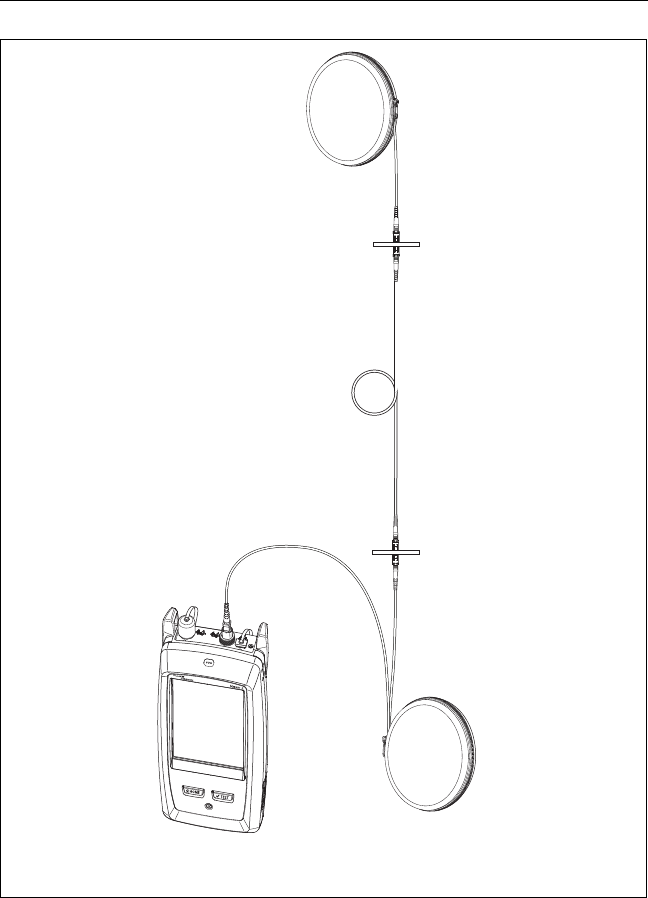
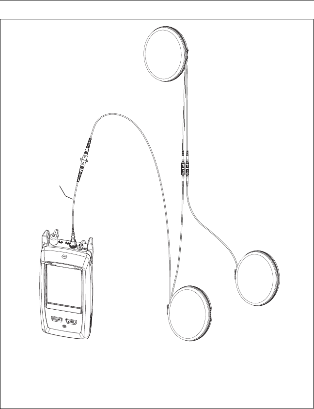
BV171.EPS
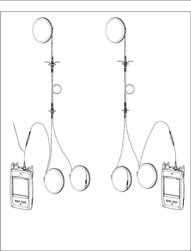
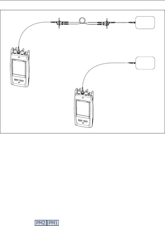
Figure 77. SmartLoop Test Connections
Launch cord
Loopback cord
(Tail Cord for Fiber A and
Launch Cord for Fiber B)
Tail cord
Fiber link
OTDR Port event for
Fiber B
End event for Fiber A
Fiber
A
Fiber
B
OTDR Port
protector
patch cord*
(30 cm, 12 in)
* Optional for tests in one direction. Recommended for bi-directional
tests to protect the OTDR port from wear.
Versiv 2 Cabling Certification Product Family
Users Manual
190
SmartLoop Results
The tester shows the SmartLoop results on two sets of EventMap,
TABLE, and TRACE screens, one for each fiber in the link. See
Figure 78.
GPU172.EPS
Figure 78. EventMap from a SmartLoop Test
The purple fiber is the loopback cord.
The fiber between the launch cord and the loopback cord is
the fiber on one side of the link.
Fiber A is the side of the link connected to the OTDR at End 1.
To switch between results for fibers A and B, tap on the
EventMap screen.
D
B
C
A

Chapter 7: Use the OTDR
The SmartLoop Test
191
Note
When you save SmartLoop results, the tester saves
the results in two records, one for each fiber in
the link.
Bi-Directional SmartLoop Tests
OTDR tests from both ends of a fiber can give different results
because some properties of fiber and fiber components can cause
differences in the loss measurements in each direction.
For example, the loss of an event is the difference between the
backscatter levels before and after the event. If a segment after a
connector or splice has a higher backscatter value than the
segment before, the tester shows different values of loss for the
connector or splice from the two directions.
For splices, which have very little loss, the difference in the
backscatter of the two fibers can cause an apparent gain in power
across the splice in one direction.
For this and other reasons, bi-directional averages of connector
and splice loss in both directions are more accurate than
measurements from one direction.
The bi-directional SmartLoop test gives you bi-directional OTDR
results for both fibers in a link. The tester also automatically
calculates averages of the two results and includes the averaged
values in the test record.
How to Do a Bi-Directional SmartLoop Test
Set up the launch compensation function
1On the home screen, tap the test setup panel, make sure the
correct SmartLoop test is selected on the CHANGE TEST screen,
then tap EDIT.
(continued)

Versiv 2 Cabling Certification Product Family
Users Manual
192
If an Auto SmartLoop test is not available, tap NEW TEST to add
one to the project. Select settings as necessary on the TEST
SETUP screen. See “Settings for OTDR Tests” on page 157.
2On the TEST SETUP screen, in the Bi-Directional panel, tap the
control to make it show On, then tap SAVE.
3On the CHANGE TEST screen, tap USE SELECTED. Select three
launch cords that have the same type of fiber as the fiber you
will test.
4On the home screen, tap the TOOLS icon, then tap Set Launch
Compensation.
5On the SET LAUNCH METHOD screen tap SmartLoop.
6Clean and inspect the OTDR port and connectors on the three
launch cords.
7Make the connections shown in Figure 76 on page 187.
8Tap SET.
9When the SET LAUNCH COMP screen shows, make sure the
tester shows the correct distances for the end of the launch
cord and the start of the tail cord.
Note
If the fibers have APC connectors, the tester
possibly will not find the correct launch and tail
events. If this occurs, do the compensation again
and select Manual Entry to enter the lengths of
the cords manually.
10 Tap SAVE.

Chapter 7: Use the OTDR
The SmartLoop Test
193
Do the SmartLoop test
1On the home screen, make sure the IDs for the fibers are
correct. The tester uses the Fiber A ID for the fiber connected
to the launch cord at the start of the test.
2Make the connections for End 1 as shown in Figure 79.
Note
To decrease the wear on the OTDR connector and
help keep it clean, use the OTDR port protector
(30 cm, 12 in) patch cord provided to connect the
OTDR to the launch and tail cords for bi-
directional SmartLoop tests.
To reduce the effect of the port protector patch
cord on results, do not use a cord longer than
50 cm (20 in).
3 Tap TEST or press .
4Halfway through the test, the tester tells you to connect the
tail cord to the OTDR port. Make the connections for End 2 as
shown in Figure 79, then tap DONE.
The tester automatically calculates bi-directional averages of
loss measurements and includes the averaged values in the
test record.
WCaution
Switch the launch and tail connections at the end
of the short patch cord. If you switch the
connectors at the patch panel, you will possibly
get less accurate results for those connections
during the second half of the test.
5If Auto Save is on, the tester uses the next two IDs to save the
results for the two fibers.
If Auto Save is off, and you tap SAVE or FIX LATER, the SAVE
RESULTS screen shows the next two IDs available. You can
change the IDs if necessary.
Versiv 2 Cabling Certification Product Family
Users Manual
194
BV176.EPS
Figure 79. SmartLoop Test Connections for a Bi-Directional Test
Launch
cord
Loopback cord
(Tail Cord for Fiber A
and Launch Cord for
Fiber B)
Tail
cord
Fiber link
Connections for
End 1
Connections for
End 2
Launch
cord
Tail
cord
Loopback cord
(Tail Cord for Fiber B
and Launch Cord for
Fiber A)
OTDR Port event
for Fiber B
OTDR Port event
for fiber A
End event
for Fiber A
End event
for Fiber B
Fiber A Fiber B Fiber A Fiber B
*Recommended for bi-directional tests to
protect the OTDR port from wear.
OTDR Port
protector
patch cord*

Chapter 7: Use the OTDR
The SmartLoop Test
195
Averaged Bi-Directional Results
Note
Unless otherwised noted, this section applies to
bi-directional results from SmartLoop tests and bi-
directional OTDR tests on single fibers.
Figure 80 shows an EventMap with averaged results from a bi-
directional SmartLoop test.
For averaged results, the tester shows the EventMap and the
event TABLE tabs, but not the OTDR tab. The averaged results do
not include Ghost events.
For Hidden events, the tester calculates the average loss of
the event that causes the hidden event, then divides that loss
among the events inside the dotted lines. For example, if the
average loss of an event is 0.24 dB, and the event causes one
event to be hidden, then the average results show 0.12 dB for
the event and 0.12 dB for the hidden event.
For these measurements, the averaged results show the larger
or the worst of the two results:
Distance between events: larger distance is shown
Reflectance: worst value is shown (for example, -30 dB is
worse than -40 dB). The reflectance measurements from
the unconnected ends are not used in the averaged
results.
Segment length: larger value is shown
Segment attenuation: larger value is shown
Fiber length: larger value is shown
Overall loss: average value is shown
Optical return loss: worse value is shown (for example,
30 dB is worse than 40 dB)
The Port Connection Quality in the averaged results is the
rating from End 1.
Versiv 2 Cabling Certification Product Family
Users Manual
196
The tester does not calculate averaged results in some
situations, for example if a launch, tail, or loopback cord was
not detected or if the distance to the end was not the same in
both directions.
GPU197.EPS
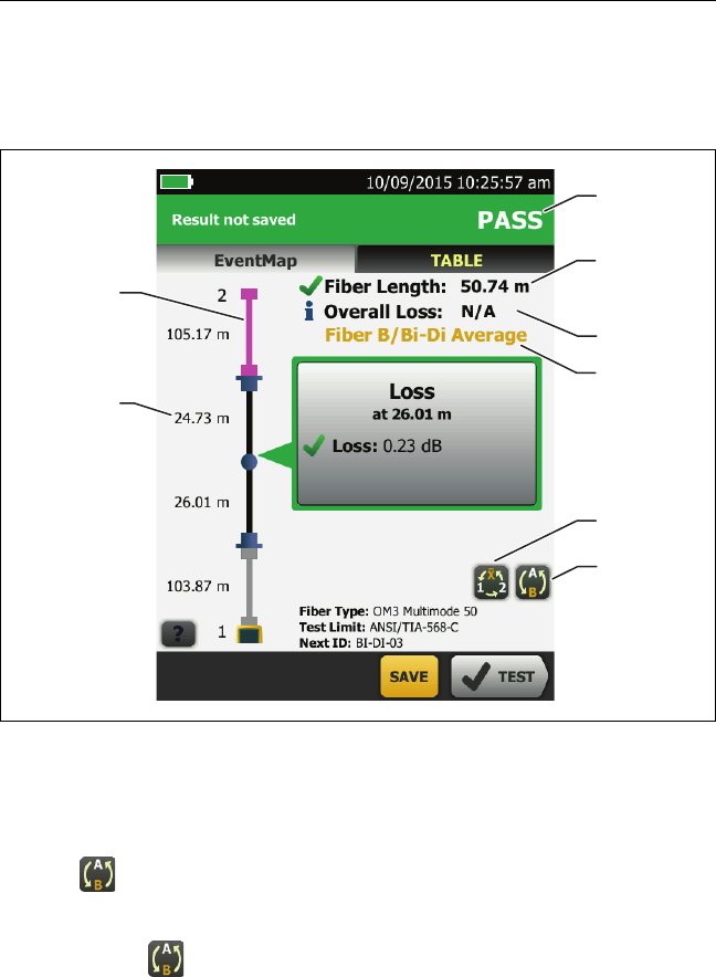
Figure 80. EventMap for Averaged, Bi-Directional SmartLoop Results
The purple fiber is the loopback cord.
The longest segment length of the two directions.
Tap this button to see the results for the other fiber (A or
B).
Touch for 3 seconds to see a summary of the results from
ends 1 and 2 on fibers A and B. To see the EventMap for a
result in the list, tap the result.
A
B
H
F
C
D
E
G

Chapter 7: Use the OTDR
The SmartLoop Test
197
This button shows with bi-directional SmartLoop results
and bi-directional OTDR results from single fibers. Tap this
button to see results from each direction (End 1 or End 2) or
the averaged results ().
This line shows which results are on the display. Use the
selection buttons ( and ) to see other results.
Overall Loss: The average loss of the two directions.
Fiber Length: The longest length of the two directions.
PASS/FAIL: The overall result for the fibers.
PASS: The averaged results passed. It is possible for one or
both directions to have FAIL results, while the overall
result is PASS.
FAIL: The averaged results failed.
Note
The tester does not use the bi-directional average
results in the calculation for the % Tested that
shows on the home screen.

Versiv 2 Cabling Certification Product Family
Users Manual
198
199
Chapter 8: Use the Visual Fault Locator
Visual Fault Locator Applications
The CertiFiber Pro and OptiFiber Pro modules include a visual
fault locator that sends a red light down the fiber. The red light
shows at the end of the fiber and at breaks, cracks, and sharp
bends along the fiber.
The VFL also helps you quickly verify the continuity of fibers,
identify connectors, and find faults along fibers and in
connectors.
The VFL helps you do these tasks:
Quickly verify the continuity of fibers.
Identify the polarity of duplex connections.
Identify connections in patch panels.
See breaks and bad splices. These faults cause the fiber to
emit red light.
See high-loss bends. If you can see the light from the VFL
at a bend in a fiber, the bend is too sharp.
See connectors that have damaged fibers inside. A
damaged fiber inside a connector causes a red light in the
connector.
Increase the quality of mechanical splices and pre-
polished connectors: Before you seal the splice or
connector, adjust the fiber alignment for the minimum
amount of light where the fibers touch. (Refer to the
instructions from the manufacturer when you make
splices and connectors.)
Versiv 2 Cabling Certification Product Family
Users Manual
200
How to Use the VFL
Figure 81 shows the equipment for tests with the visual fault
locator.
Figure 81. Equipment for Visual Fault Locator Tests
BV137.EPS
Versiv 2 main unit with
CertiFiber Pro or OptiFiber Pro
module installed
One patch cord to connect the
tester to the fiber (optional)
FI-1000 video probe with USB
connector
Fiber cleaning supplies
AC adapter (optional)
A
BCE
D

Chapter 8: Use the Visual Fault Locator
How to Use the VFL
201
To use the visual fault locator
Note
You can connect the visual fault locator to
connectors that have 2.5 mm ferrules (SC, ST, or
FC). To connect to other ferrule sizes, use a test
reference cord with the correct connector at one
end and a SC, ST, or FC connector at the tester
end.
1Clean and inspect the connectors on the patch cord, if used,
and the fiber to be tested.
2Connect the fiber directly to the VFL port or use the patch
cord to connect to the port.
3Use the VFL button to turn on the visual fault locator (refer to
Figure 82).
Or, on the home screen tap TOOLS, then tap Visual Fault
Locator (VFL). You can tap the PULSE/OFF/CW (continuous
wave) button on the screen to change the modes of the VFL, or
use the button as shown in Figure 82.
4Look for the red light as shown in Figure 82.
5To see the light that comes out of a connector, hold a white
paper in front of the fiber connector.
Notes
The fiber connector at the VFL and the fiber near
the connector can emit red light when there are
no faults there because the light is strong at the
VFL output.
The light from the VFL is possibly not visible
through dark-colored fiber jackets.
Versiv 2 Cabling Certification Product Family
Users Manual
202
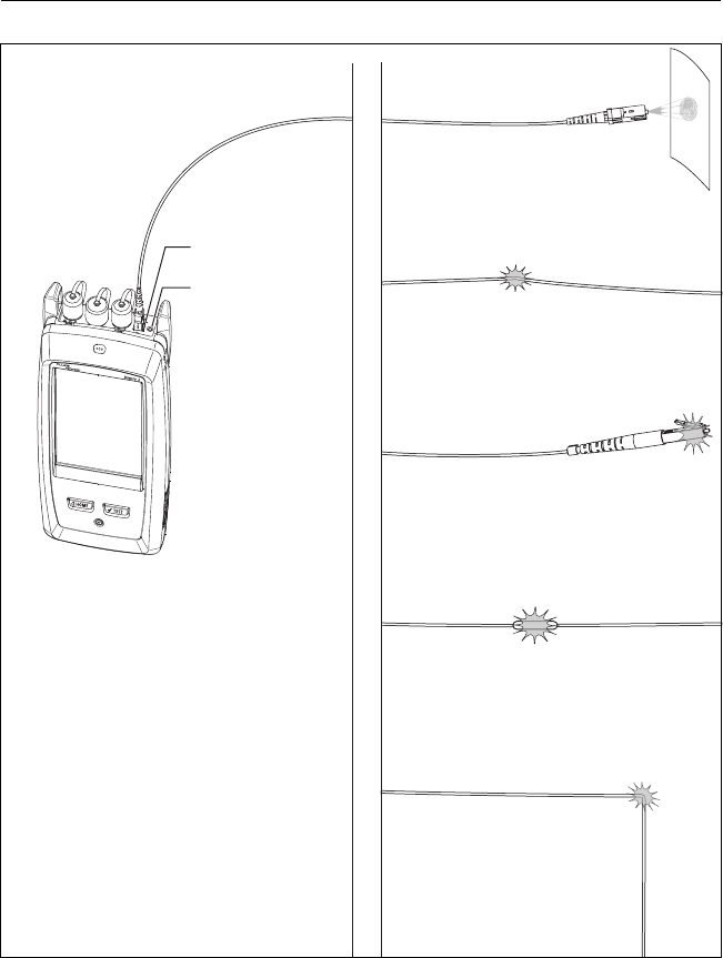
BV07.EPS
Figure 82. How to Use the Visual Fault Locator
VFL button
Verify continuity
and identify fibers
Find microbends and
broken fibers
Find connectors that have
broken fibers inside
Find splices that have
broken fibers inside
Find bends that
are too sharp
VFL connector
1 Press the VFL button: VFL is
on (CW, continuous wave).
2 Press again: VFL flashes
(PULSE).
3 Press again: VFL is off.
203
Chapter 9: Monitor Optical Power
You can use the CertiFiber Pro main tester to monitor and save
measurements of optical power and loss, and you can use the
main or remote tester and as an optical power source. You can
use the main tester’s power or loss meter and its light source at
the same time.
How to Monitor Power and Loss
The power meter lets you monitor the optical power supplied by
a source such as an optical network interface card or optical test
equipment. You can do these tasks:
Monitor minimum and maximum power levels in dBm
(decibels per milliwatt), mW (milliwatts), µW (microwatts),
or nW (nanowatts.
Monitor power loss compared to a reference level.
Auto CertiFiber Pro and Auto SimpliFiber Pro modes let
you monitor power and loss at two wavelengths when
you use a CertiFiber™ Pro or SimpliFiber® Pro source.
Save power and loss measurements for two wavelengths
in one record.
Figure 83 shows the equipment for meter measurements.
Notes
It is not necessary to select a Fiber Type or Test
Limit when you monitor power or loss. These tests
do not have PASS/FAIL results.
Power and loss measurements from sources that
transmit network data can change as the data
rate changes.
Versiv 2 Cabling Certification Product Family
Users Manual
204
Figure 83. Equipment for Power Meter Measurements
To monitor power
1Clean and inspect the tester’s input port and the connectors
on the source and test reference cord.
2Connect the tester to the source, as shown in Figure 84.
3Turn on the source. On a CertiFiber Pro module, hold down
the button adjacent to the VFL port for 3 seconds.
4On the home screen, tap TOOLS, then tap Power Meter /
Light Source.
5The default mode for the power meter is Auto CertiFiber Pro.
If the source is not a CertiFiber Pro tester, tap to select the
correct mode.
Figure 85 shows the power meter and its controls.
BV137.EPS
Versiv 2 main unit with
CertiFiber Pro module installed
One test reference cord
Fiber cleaning supplies
FI-1000 video probe with USB
connector
AC adapter (optional)
A
BCE
D
Chapter 9: Monitor Optical Power
How to Monitor Power and Loss
205
BV138.EPS
Figure 84. Connections to Monitor Power and Loss
To monitor loss
On the POWER METER / LIGHT SOURCE screen, tap REF to use the
present power level as a reference. The meters show the difference
between the reference power levels and the measured power levels.
To save the power and loss measurements
1On the POWER METER / LIGHT SOURCE screen, tap SAVE.
2On the SAVE RESULT screen, select End 1 or End 2, make sure
the Cable ID and End name are correct, then tap SAVE. Saved
power meter results show these icons for End 1 and
End 2:
The tester saves the present, minimum, maximum, and reference
power and loss measurements for both wavelengths in one record.
Power at the
end of a link
Power from an
optical source
Optical network
interface card or
optical power source
Versiv 2 Cabling Certification Product Family
Users Manual
206
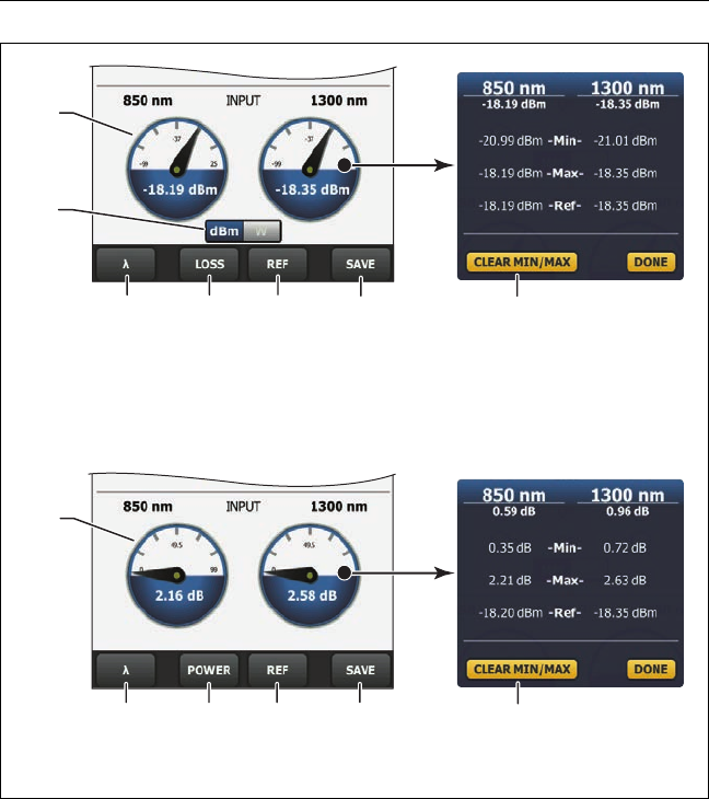
GPU126.EPS
Figure 85. Power Meter Measurements and Controls
The meters show the power levels received on the input port.
This control shows when the meters measure absolute power.
Tap the control to see the power measurement in dBm (decibels
per milliwatt), mW (milliwatts), µW (microwatts), or nW
(nanowatts.
J
B
A
I
FEC
F
C D H
E
G
G
H
Power measurements
Loss measurements

Chapter 9: Monitor Optical Power
How to Control the Light Source
207
To select a wavelength for the power meter, tap .
Use the Auto CertiFiber Pro and Auto SimpliFiber Pro modes
only with a CertiFiber Pro or SimpliFiber Pro source. In these
modes, the tester reads the wavelength identifiers transmitted
by the source to know when to measure power at each
wavelength.
To monitor power loss (), tap LOSS or REF.
When you tap REF, the tester saves the present measurements as
reference levels and the meters show power loss ().
To save the power and loss measurements, tap SAVE.
To see the present, minimum, maximum, and reference power or
loss levels, tap a meter.
To set the minimum and maximum values to zero, tap CLEAR
MIN/MAX in the Min/Max/Ref window.
When you tap LOSS or REF, the meters show power loss. The
loss is the difference between the reference power levels and
the measured power levels.
To monitor absolute power, tap POWER.
How to Control the Light Source
When you do tests in Far End Source mode, you use the button on
the module to turn on the remote’s light source manually. You
can also turn on the main tester’s light source manually and use
the main tester as an optical source.

Versiv 2 Cabling Certification Product Family
Users Manual
208
Use the Display to Control the Main Tester’s Light Source
1Clean and inspect all connectors you will use.
2Connect the tester’s output port to the power meter.
If your tester has a CertiFiber Pro Quad module installed, make
sure you connect the fiber to the correct output port.
3On the home screen tap TOOLS, tap Power Meter / Light
Source, then select settings for the source. See Figure 86.
Use the Module’s Button to Control the Light Source
The button next to the VFL port puts the output port in auto
wavelength mode. In this mode, the port transmits both
wavelengths (850 nm and 1300 nm or 1310 nm and 1550 nm). The
signal includes identifiers that tell the meter when to measure
power at each wavelength. Use this mode only with a CertiFiber
Pro or SimpliFiber Pro power meter.
Note
The remote source always operates in auto
wavelength mode.
1Clean and inspect all connectors you will use.
2Connect the tester’s output port to the power meter.
If your tester has a CertiFiber Pro Quad module installed, make
sure you connect the fiber to the correct output port.
3Hold down the button adjacent to the VFL port for 3 seconds.
On CertiFiber Pro Quad modules, to turn on the singlemode
source, press the button again.
On a main tester used as a source, you can use the POWER
METER / LIGHT SOURCE screen to select different settings for
the source. See Figure 86.
Chapter 9: Monitor Optical Power
How to Control the Light Source
209
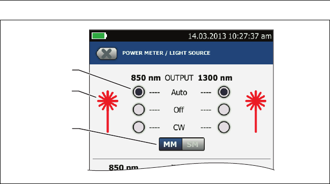
GPU127.EPS
Figure 86. Light Source Controls for the Main Tester
Use the buttons to control the output port when you use the
main tester as a light source:
Auto: In this mode, the output port transmits both
wavelengths. The signal includes identifiers that tell a
CertiFiber Pro or SimpliFiber Pro power meter when to
measure power at each wavelength. Use this mode only
with a CertiFiber Pro or SimpliFiber Pro power meter.
Off: The output port does not transmit the selected
wavelength.
CW: The output port transmits a continuous signal at one
wavelength. Use this mode if the power meter is not a
CertiFiber Pro or SimpliFiber Pro meter.
The laser icon is red when the output port transmits the
wavelength adjacent to the icon.
When the tester has a CertiFiber Pro Quad module installed, use
this control to select multimode or singlemode wavelengths
A
C
B

Versiv 2 Cabling Certification Product Family
Users Manual
210
211
Chapter 10: Manage Test Results
View Saved Results
On the home screen, tap the RESULTS icon. The RESULTS screen
shows the results in the active project. See Figure 87.
To view results saved on a USB flash drive, connect the drive, then
tap RESULTS, TRANSFER, USB Flash Drive, Import. See “Manage
Results on a Flash Drive” on page 218.
To organize results and make reports you can give to customers,
use LinkWare PC software.
Versiv 2 Cabling Certification Product Family
Users Manual
212
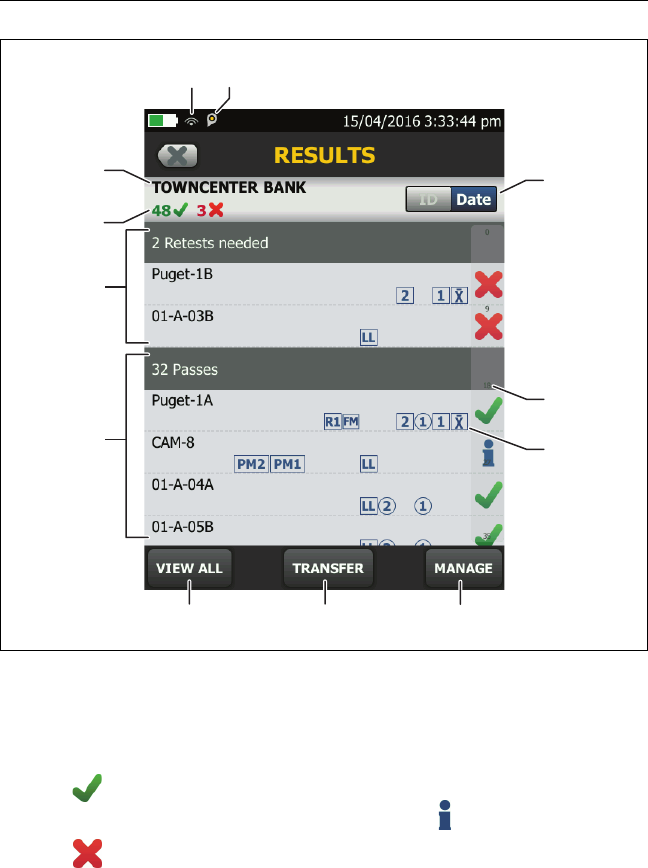
HEJ24.EPS
Figure 87. RESULTS Screen
The name of the active project.
: The number of results that passed. This includes individual
results for each ID and tests that have an result.
: The number of results that failed. This includes individual
results for each ID.
L
C
D
A
B
E F G
J
I
H
K

Chapter 10: Manage Test Results
View Saved Results
213
: The number of DSX CableAnalyzer results that have PASS*
results. PASS* results have measurements within the range of
accuracy uncertainty for the tester. See “PASS*/FAIL* Results” on
page 51.
Note
IDs can contain multiple results. So, these numbers
can be more than the number of IDs saved.
The cable IDs that have FAIL results and must be tested again.
Because some IDs can have one or more tests that failed, the
number at the top of this screen () can be more than the
number of retests needed.
The cable IDs that have an overall PASS or result. Because
some IDs can have one or more tests that passed or have an
status, the number at the top of this screen () can be more
than the number of passes.
IDs that start with “TRC” are from verification tests on fiber
test reference cords. These IDs show the date and time of the
test.
Tap VIEW ALL to see a summary of the results in all the projects
in the tester.
TRANSFER lets you export or import results to or from a flash
drive and delete results on the flash drive.
MANAGE lets you move results to a different project, rename
results, or delete results that are in the tester.
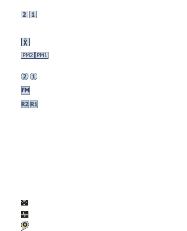
The icons show the types of fiber test results that the result
contains:
No icon: DSX CableAnalyzer results from copper cabling.
Loss/length results from a CertiFiber Pro OLTS module.
Versiv 2 Cabling Certification Product Family
Users Manual
214
OptiFiber Pro OTDR results from End 2 and End 1. The
result can be from an Auto, Manual, SmartLoop, or
DataCenter OTDR test.
Averaged results from a bi-directional OTDR test.
Power meter results from End 2 and End 1 from a
CertiFiber Pro OLTS module.
FiberInspector results from End 2 and End 1.
FaultMap results from an OptiFiber Pro OTDR module.
Real Time Trace results from End 2 and End 1 from an
OptiFiber Pro OTDR module.
The scroll bar shows when the list of results is long. To use the
scroll bar, tap on the bar or slide your fingertip on the bar. For
example, to see the 12th result in the list, tap on “12” in the
scroll bar. When you slide your fingertip on the bar, the number
of the result you can see is next to your fingertip.
Tap the ID/Date control to sort the results by cable ID or by date.
When you sort by ID, the results show in ascending order. When
you sort by date, the latest result is at the top of the list.
These icons show when you connect the tester to a network
to use Fluke Networks cloud services (see Chapter 12):
The tester is connected to a wireless network.
The tester is connected to a wired network.
The asset management icon shows when the owner of a
LinkWare Live account has enabled the asset management
service on the tester. See “About the Asset Management Service”
on page 238.

Chapter 10: Manage Test Results
How to Add a Result to a Saved Result
215
How to Add a Result to a Saved Result
You can save the results from different tests in one cable ID. For
example, you can save CertiFiber Pro results and FiberInspector
results together in one ID.
When you add results, these settings used to get the results must
agree with the settings in the saved result:
Test limit
Fiber categories (singlemode/multimode, core size, category)
Index of refraction (makes a warning you can override)
If the settings do not agree, the tester shows a warning.
To add results for a different End setting
1Do the test, then tap SAVE.
2On the SAVE RESULT screen, select End 1 or End 2, make sure
the Cable ID and End name are correct, then tap SAVE.
To add results from a different test
1On the home screen, tap the test setup panel.
2On the CHANGE TEST screen, tap the button next to a test,
then tap USE SELECTED.
If the ID set has a Last ID, the home screen shows the first
ID in the set that does not have results for the test you
selected.
If the ID set does not have a Last ID, tap the Next ID panel,
tap the Next ID box on the CHANGE ID screen, enter the
first ID for the set of saved results, then on the CHANGE ID
screen, tap DONE.
3Tap TEST or press , then save the result.

Versiv 2 Cabling Certification Product Family
Users Manual
216
How to Replace a Saved Result that Failed
To use the same test settings that were used for the saved result
1On the home screen, tap the RESULTS icon.
2On the RESULTS screen, tap a result that failed.
3Tap TEST AGAIN.
4When the test is completed, and if Auto Save is on, the tester
asks you if you want to overwrite the results. Tap Yes.
If Auto Save is off, tap FIX LATER (if the test failed) or SAVE (if
the test passed) to save the result.
To replace a result with a result that uses different test settings
1Turn off Auto Save.
2Make sure that the home screen shows the project that
contains the result you want to replace.
3Select the necessary test settings.
4Do the test, tap FIX LATER (if the test failed) or SAVE (if the
test passed), then enter the ID of the saved result.
5The tester asks you if you want to overwrite the results. Tap
Yes.
Delete, Rename, and Move Results
Before you delete, rename, or move results, select the project that
contains the results and go to the MANAGE RESULTS screen:
1On the home screen, tap the RESULTS icon. The RESULTS
screen shows the results in the active project.
2To see the results in another project, tap VIEW ALL, then tap a
project.
3Tap MANAGE to see the MANAGE RESULTS screen.

Chapter 10: Manage Test Results
Delete, Rename, and Move Results
217
To delete results
1On the MANAGE RESULTS screen, select the results you want
to delete.
To select all the tests that failed or all the tests that passed,
tap Select All Retests or Select All Passes.
2Tap DELETE, then tap DELETE in the confirmation dialog.
To rename results
1On the MANAGE RESULTS screen, select one result to rename.
2Tap RENAME.
3Enter a new name, then tap DONE.
To move results to a different project
1On the MANAGE RESULTS screen, select the results you want
to move.
2Tap MOVE.
To move the results to a project shown in the list, tap the
project name, then tap MOVE in the confirmation dialog.
To make a new project and move the results to the new
project, tap NEW PROJECT, enter a project name, tap
DONE, then tap MOVE in the confirmation dialog.
Note
When you move results to a different project, that
project becomes the active project.

Versiv 2 Cabling Certification Product Family
Users Manual
218
Manage Results on a Flash Drive
You can export or import results to or from a flash drive, and
delete results on the flash drive.
To export or import project settings along with results, see
“Manage Projects on a Flash Drive” on page 228.
WCaution
Do not remove the USB flash drive while the LED on
the drive flashes. Doing so can corrupt the data on
the drive.
You can lose a USB flash drive, cause damage to it,
or accidentally erase the contents of the drive. Thus,
Fluke Networks recommends that you save no more
than one day of test results on a flash drive.
Note
The tester reads only USB drives that use the FAT
format.
1Connect a USB flash drive to the type A USB port. The tester
makes a bell sound when it detects the drive.
2On the home screen, tap the RESULTS icon, then tap
TRANSFER.
3On the TRANSFER RESULTS screen, tap USB Flash Drive, then
tap a function:
Export: On the EXPORT RESULTS screen, select New or All,
select the project that contains the results you want to
export to the flash drive, then tap EXPORT.
New: Export only results that do not have the same IDs as
results that are already on the flash drive.
All: Export all the results from all projects in the tester.
Note
Cable IDs are case-sensitive. For example, the
tester saves result with the names “A0” and “a0”
in two different records.

Chapter 10: Manage Test Results
Upload Results to a PC
219
Import: On the IMPORT RESULTS screen select the project
that contains the results you want to import from the
flash drive, then tap IMPORT.
Delete: On the DELETE RESULTS screen select the project
that contains the results you want to delete on the flash
drive, then tap DELETE.
Upload Results to a PC
Note
To upload results to the cloud for transfer to a PC,
use the LinkWare Live web application. See
Chapter 12.
To upload results to a PC from the tester or a flash drive, use
LinkWare PC software.
1Install the latest version of LinkWare PC software on the PC.
2Turn on the tester and start LinkWare PC on the PC.
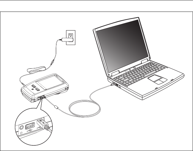
3Use the USB cable supplied to connect the Micro-AB USB port
on the tester to a type A USB port on the PC. See Figure 88.
Or connect a USB flash drive to the PC.
4On the LinkWare PC toolbar, click , then select a product,
or select Test Files (.tst) to upload from a flash drive.
5In the Import dialog box in LinkWare PC, select options for
the location and the number of results to import.
Versiv 2 Cabling Certification Product Family
Users Manual
220
BV46.EPS
Figure 88. How to Connect the Tester to a PC
View the Memory Status
To see the memory status
On the home screen, tap the TOOLS icon, then tap Memory
Status.
The MEMORY STATUS screen shows these values:
The percentage of memory available
The number of test records that are saved
The number of .id files that have been downloaded to the
tester from LinkWare PC software
The memory space taken by other files, such as the databases
for projects and test limits
Micro-AB
USB port
Type A
USB port
AC adapter
221
Chapter 11: Use Projects
Why Use Projects?
The tester’s ProjX™ management system lets you set up projects
that help you monitor the status of a job and make sure that your
work agrees with the requirements of the job.
You can use a project to do these tasks:
Specify the tests that are necessary for a job.
Specify settings for tests.
Specify an operator for the job.
Make sets of sequential IDs to use as names for test results.
Automatically save test results with IDs from a set.
Add the results from other necessary tests to each saved result
in the project.
See which IDs do not have results for a specified test.
See what percentage of a job is completed.
See how many links passed and how many failed.
Keep the test results from a job in one place for easy access.
When you use a project, you can do tests and use IDs that are not
specified in the project if necessary. You can also easily change
the settings in a project if necessary.
Notes
It is not necessary to install a module to set up a
project for the module. The tester keeps all
settings in the main Versiv 2 unit.
To manage projects in the cloud, use the
LinkWare Live web application. See Chapter 12.

Versiv 2 Cabling Certification Product Family
Users Manual
222
Set Up a Project
Refer to the PROJECT screen in Figure 89 on page 223.
1On the home screen, tap the PROJECT panel, tap CHANGE
PROJECT, then tap NEW PROJECT.
2On the NEW PROJECT screen, enter a name for the project,
then tap DONE.
3On the PROJECT screen, tap the Operator panel to enter an
operator name for the project.
4On the PROJECT screen, tap the NEW TEST button to enter
the tests and test settings necessary for the project.
5On the PROJECT screen, tap the NEW ID SET button to make
one or more sets of cable IDs for the project. See the CABLE ID
SETUP screen in Figure 90 on page 226.
6On the PROJECT screen, tap DONE.
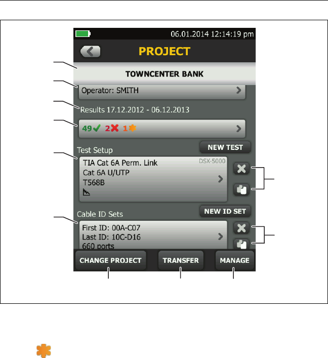
The PROJECT Screen
To start a new project, tap the PROJECT panel on the screen.
Figure 89 shows the PROJECT screen and describes the items you
enter to make a project.
The name of the project. See also item .
Operator: The name of the person who will do the tests for the
project. For each operator you can also enter the email address
that the operator will use as an ID to sign in to LinkWare Live.
The date range for the results in the project.
Results: A summary of the test results in the project:
: The number of tests that failed.
: The number of tests that passed.
Chapter 11: Use Projects
The PROJECT Screen
223
GPU08.EPS
Figure 89. PROJECT Screen
: The number of DSX CableAnalyzer results that have PASS*
results. PASS* results have measurements within the range of
accuracy uncertainty for the tester. See “PASS*/FAIL* Results” on
page 51.
Test Setup: The tests that are available in the project.
To add a test to the project, tap NEW TEST.
Cable ID Sets: The sets of IDs the tester can use for the names of
test results. Each ID set is for either copper or fiber cable.
To add a set of IDs to the project, tap NEW ID SET. See Figure 90.
J
A
B
G
E
F
H
C
D
J
I

Versiv 2 Cabling Certification Product Family
Users Manual
224
To use a different project, tap CHANGE PROJECT, then tap a
project.
To make a new project, tap CHANGE PROJECT, then tap NEW
PROJECT.
TRANSFER lets you export or import projects to or from a flash
drive and delete projects on the flash drive. The project data
includes all project settings and test results.
MANAGE lets you rename, copy, or delete a project that is in the
tester.
To delete the test setup or ID set, tap . To copy the test setup
or ID set so you can edit it to make a new one, tap .
Notes
If you delete an imported ID set from a project,
the ID set is still available in the tester. To delete
imported ID sets from the tester, use LinkWare PC
software.
A project must have at least one Test Setup and
one Cable ID set. If you delete them all, the tester
makes a default Test Setup and Cable ID set.

Chapter 11: Use Projects
The CABLE ID SETUP Screen
225
The CABLE ID SETUP Screen
To see the CABLE ID SETUP screen, tap the PROJECT panel on the
home screen, then tap NEW ID SET on the PROJECT screen. See
Figure 90 on page 226.
Each project can have up to 5000 IDs. If an ID set does not have a
Last ID, the tester counts the set as one ID. An ID can have a
maximum of 60 characters. Symbols, such as the asterisk, and
accented characters do not increment.
About Next ID Sets
If you do not enter a Last ID when you make an ID set, the tester
uses the First ID as the Next ID. The tester increments the Next ID
each time you save a result.
Numbers increment sequentially:
1, 2, 3, 4, 5, 6, 7, 8, 9, 10, 11, 12, ... 99, 100, 101...
Letters increment through the English alphabet:
A, B, C, D, ... Z, AA, AB, AC, AD, ... AZ, BA, BB, BC...
Numbers and letters do not cause each other to increment:
1Y, 1Z, 1AA, 1AB, ... 1ZZ, 1AAA, 1AAB...
The tester does not increment symbols or accented characters.
When you use a Next ID set, the set under IDs Untested on the
CHANGE ID screen shows only the next ID. To save the next test
with a different ID, tap the Next ID: panel, then enter a different
ID.
Each project can have one Next ID set. You can use the Next ID set
for copper or fiber results.
If your project has only a Next ID set, the tester cannot calculate
the percentage of the project that is completed, so the % Tested
value does not show on the home screen.
Versiv 2 Cabling Certification Product Family
Users Manual
226
If your project has both a Next ID set and sets with first and last
IDs, the % Tested value includes tests you saved with Next ID. For
example, if you have one Next ID set and one set with 10 IDs, and
you save 10 results with next IDs, the % Tested shows 50% (10
saved results divided by 20 IDs).
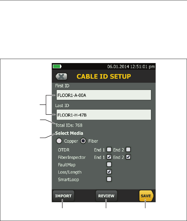
GPU09.EPS
Figure 90. CABLE ID SETUP Screen
(after you enter the first and last IDs)
First ID and Last ID: The first and last IDs in a set of sequential IDs.
If you do not enter a Last ID when you make an ID set, the tester
will increment the First ID to make subsequent IDs.
A
B
E F
C
D

Chapter 11: Use Projects
About Next ID Sets
227
Note
The tester does not increment symbols or
accented characters.
When you use an ID set that does not have a Last ID, the set
under IDs Untested on the CHANGE ID screen shows only the
next ID.
Total IDs: The number of IDs in the set. This section does not
show for ID sets that do not have a Last ID.
Select Media: Select Copper to use the ID set for test results
from copper cable.
Select Fiber and one or more fiber tests to use the ID set for test
results from fiber cable.
For example, you can specify that you must do a Loss Length
and a FiberInspector test for each ID. After you do both tests for
all the IDs in the set, the tester shows 100% Tested on the home
screen. If no IDs include FiberInspector results, the tester shows
50%. To see the IDs that need FiberInspector results, select a
FiberInspector test in the project, then look at the list under
FiberInspector IDs Untested on the CHANGE ID screen
Notes
You can use an ID set only for results from the
media type you selected under Select Media.
The Select Media section does not show for ID sets
that do not have a Last ID. You can use these ID
sets for copper or fiber results.
Tap IMPORT to use an ID set that you downloaded to the tester
from LinkWare PC software.
Tap REVIEW to see the CABLE ID REVIEW screen, which shows
the ID set an the total number of IDs.
Note
The REVIEW button does not show if you do not
enter a Last ID.
SAVE: To save the ID set, tap SAVE.

Versiv 2 Cabling Certification Product Family
Users Manual
228
Manage Projects on a Flash Drive
You can export or import projects to or from a flash drive, and
delete projects on the flash drive. The project data includes all
project settings, test results, and ID sets.
WCaution
Do not remove the USB flash drive while the LED on
the drive flashes. Doing so can corrupt the data on
the drive.
You can lose a USB flash drive, cause damage to it,
or accidentally erase the contents of the drive. Thus,
Fluke Networks recommends that you save no more
than one day of test results on a flash drive.
Note
The tester reads only USB drives that use the FAT
format.
1Connect a USB flash drive to the type A USB port. The tester
makes a bell sound when it detects the drive.
2On the home screen, tap the PROJECT panel.
3On the PROJECT screen, tap TRANSFER.
4On the TRANSFER PROJECTS screen, select a function:
Export: On the EXPORT PROJECTS screen, select the
projects you want to export to the flash drive, then tap
EXPORT.
Import: On the IMPORT PROJECTS screen select the
projects you want to import from the flash drive, then tap
IMPORT.
Delete: On the DELETE PROJECTS screen select the
projects you want to delete on the flash drive, then tap
DELETE.

Chapter 11: Use Projects
Copy Project Settings to Other Testers
229
Copy Project Settings to Other Testers
To copy the settings in a project to other Versiv testers, use the
Read Project Setups and Write Project Setups utilities in LinkWare
PC software. You can use LinkWare PC to read project settings
from a tester or from a project you exported to a flash drive.

Versiv 2 Cabling Certification Product Family
Users Manual
230
231
Chapter 12: Sync Projects with
LinkWare™ Live
The LinkWare Live web application lets you manage your projects
from a desktop or mobile device.
Sign Up for a LinkWare Live Account
1Go to www.linkwarelive.com/signin.
2If you already have a LinkWare Live account, enter your email
address and password on the LinkWare Live Sign In page.
3If you do not have a LinkWare Live account, click New user?
Sign up now!. Enter the information for your account, then
click CREATE ACCOUNT.
Fluke Networks sends you an email with a LinkWare Live
activation code.
4Open the email, copy the activation code, click the LinkWare
Live activation link in the email, paste the activation code into
the box in the activation window, then click ACTIVATE.
5The LinkWare Live Sign In page shows again. Enter your email
address and password, then click SIGN IN.

Versiv 2 Cabling Certification Product Family
Users Manual
232
How to See the Tester’s MAC Address
Some networks require users to register their device’s MAC
address before they can connect to the network.
There are two MAC addresses: one for the wired port and one for
the Wi-Fi adapter.
To see the tester’s or Wi-Fi adapter’s MAC address
1On the home screen tap TOOLS, then tap Network.
2On the NETWORK screen, tap the Wired or Wi-Fi panel. The
MAC addresses shows at the top of the WIRED and WI-FI PORT
screens.
Use LinkWare Live Through a Wired Ethernet
Network
1Use an appropriate cable to connect the tester’s RJ45 Ethernet
port to an active network port. If the cable is good and the
port is active, the LEDs on the tester’s port will come on.
2On the home screen, make sure the Operator name is correct.
The tester uses the email address associated with the operator
name as the ID when you sign in to LinkWare Live.
If no address is associated with the name, or if you enter a
different address on the LWL SIGN IN screen, the tester
associates the name with the address you enter.
3On the home screen, tap the SYNC icon.
4When the tester connects to the network, the wired network
connection icon shows at the top of the screen:
5On the LWL SIGN IN screen, if necessary, enter the ID and
password for your LinkWare Live account, then tap SIGN IN.
6If you use other people’s LinkWare Live accounts, the
ORGANIZATION screen shows. Tap the organization you want
to use.

Chapter 12: Sync Projects with LinkWare™ Live
Use LinkWare Live Through a Wi-Fi Ethernet Network
233
7On the SYNC PROJECTS screen (Figure 91 on page 235), select
the projects you want to sync, then tap SYNC.
Use LinkWare Live Through a Wi-Fi Ethernet
Network
The tester can use wireless network channels 1 through 11.
1On the home screen, make sure the Operator name is correct.
The tester uses the email address associated with the operator
name as the ID when you sign in to LinkWare Live.
If no address is associated with the name, or if you enter a
different address on the LWL SIGN IN screen, the tester
associates the name with the address you enter.
2On the home screen, tap the SYNC icon.
3Select a wireless network if necessary.
If the network setting are not correct, the tester shows the
NETWORK screen and a message about the necessary settings.
a. To change the settings, tap the Wi-Fi panel.
b. To test the settings, go back to the WI-FI PORT screen, then
tap CONNECT.
When the tester connects to the network, the Wi-Fi
network connection icon shows at the top of the screen:
c. Go back to the TRANSFER RESULTS screen, then tap the
LinkWare Live panel.
4On the LWL SIGN IN screen, if necessary, enter the ID and
password for your LinkWare Live account, then tap SIGN IN.
5Enter a user name and password for the network, if necessary.
-continued-

Versiv 2 Cabling Certification Product Family
Users Manual
234
6If you use other people’s LinkWare Live accounts, the
ORGANIZATION screen shows. Tap the organization you want
to use.
7On the SYNC PROJECTS screen (Figure 91), select the projects
you want to sync, then tap SYNC.
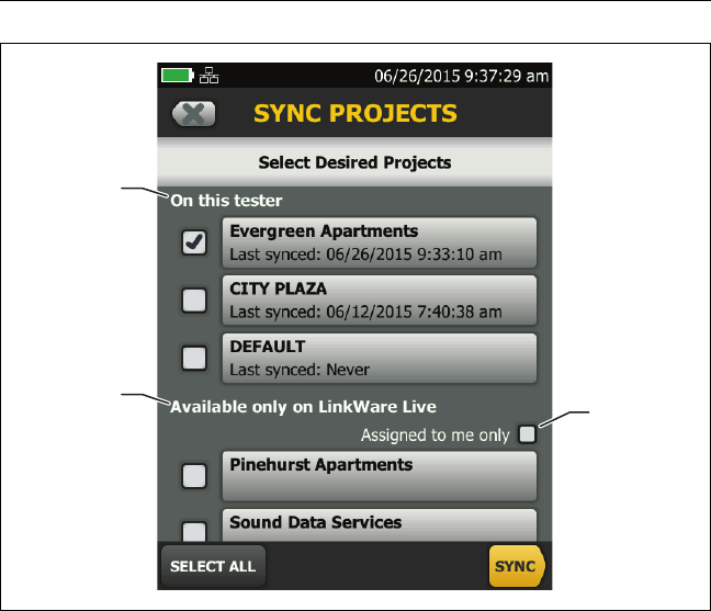
See Figure 91:
Projects in the On this tester section are possibly also in
LinkWare Live. You can upload results from these projects to
LinkWare Live.
If the project in LinkWare Live has test settings or cable IDs that
are different from those in the tester, you can download the
new settings to the tester.
By default, the active project is selected to sync.
Projects in the Available only on LinkWare Live section have
project settings you can download to the tester.
Chapter 12: Sync Projects with LinkWare™ Live
Use LinkWare Live Through a Wi-Fi Ethernet Network
235
GPU190.EPS
Figure 91. SYNC PROJECTS Screen
If you download these projects, only test settings and cable IDs
are downloaded. Any test results saved in the project in
LinkWare Live are not downloaded.
If you select Assigned to me only, you will see only projects that
are assigned to you in the project settings in LinkWare Live.
A
BC

Versiv 2 Cabling Certification Product Family
Users Manual
236
Change the Network Settings
It is not usually necessary to change the wired or Wi-Fi network
settings before you try to make a connection. But for example if
you must use static addressing, you can get to the settings on the
NETWORK screen.
To get to the network settings
On the home screen, tap TOOLS, then tap Network, then tap the
Wired or Wi-Fi panel.
To test the settings
Tap CONNECT on the WI-FI PORT or WIRED PORT screen.
Settings for the Wired Port
The tester can use DHCP (dynamic host configuration protocol) or
Static for the address method. Most networks use DHCP.
For Static, enter an IP address for the tester and the Subnet Mask,
Gateway address, and DNS1 and DNS2 addresses for the network.
If you are not sure what to enter, speak to the network
administrator.
Settings for Wi-Fi
Table 8 shows the Wi-Fi settings.

Chapter 12: Sync Projects with LinkWare™ Live
Change the Network Settings
237
Table 8. Settings for the Wi-Fi Connection
Setting Description
Address Most networks use DHCP.
DHCP
address
settings
SSID: The tester does a scan for wireless networks and shows a
list of available networks. Select the correct SSID.
To connect to a hidden network, tap ADD SSID.
Security:
Authentication: Select the authentication type that the
network uses:
Open: Security credentials are not necessary.
WEP: Select an encryption method and enter the
necessary keys.
WPA/WPA2 Personal: Enter the password for the
network.
WPA/WPA2 Enterprise:
EAP: Select an EAP type that is appropriate for the
authentication server.
User and Password: Enter a user name (login name) and
password for the network.
Alternate ID: The tester can use the Alternate ID with
some EAP methods to send an empty or anonymous
identity while the tester makes a private connection. The
tester then uses the private connection to send the User
name and Password you entered.
The tester can also use the Alternate ID to send the User
name and Password to an authentication server in a
different realm. In this situation, the Alternate ID can
have a format such as anonymous@MyCompany.com or /
MyCompany/anonymous.
Static
address
settings
Enter an IP address for the tester and the Subnet Mask,
Gateway address, and DNS1 and DNS2 addresses for the
network. If you are not sure what to enter, speak to the
network administrator.
The Security settings are the same as for the DHCP address
settings.

Versiv 2 Cabling Certification Product Family
Users Manual
238
Delete Wi-Fi Settings and Passwords
The tester saves the security settings and passwords for the Wi-Fi
connections you use.
To delete all Wi-Fi settings and passwords
On the home screen, tap TOOLS, then tap Network, tap the Wi-Fi
panel, then tap FORGET ALL.
About the Asset Management Service
LinkWare Live’s asset management service lets you see the
locations of your Versiv testers in the field. The owner of the
LinkWare Live account can enable or disable the service remotely
for each Versiv tester.
When this service is enabled on a Versiv tester, the asset
management icon ( ) shows on the tester’s home screen. When
a technician uses the tester to sign in to LinkWare Live, the
tester’s location shows on a map on LinkWare Live’s ASSETS page.
Note
You can enable or disable the asset management
service only with LinkWare Live. There is no
setting on the Versiv tester that enables or
disables this service.
Sign Your Tester Out of LinkWare Live
1On the home screen, tap the TOOLS icon, then tap Sign In.
2On the LWL SIGN IN screen, tap SIGN OUT.
Or, turn off the tester.

Chapter 12: Sync Projects with LinkWare™ Live
Import Projects from LinkWare Live into LinkWare PC
239
Sign In to LinkWare Live from a Desktop or
Mobile Device
1Go to https://www.linkwarelive.com/signin.
2Enter your LinkWare Live user name and password, then click
SIGN IN.
For more information about how to use LinkWare Live, click HELP
on the LinkWare Live web page.
Import Projects from LinkWare Live into
LinkWare PC
1Install the latest version of LinkWare PC software on the PC.
2Turn on the tester and start LinkWare PC on the PC.
3Use the USB cable supplied to connect the Micro-AB USB port
on the tester to a type A USB port on the PC.
4On the LinkWare PC toolbar, click .
5Sign in to your LinkWare Live account, then use the LinkWare
PC dialog boxes to select and import projects.
Learn More About LinkWare Live
Go to http://www.flukenetworks.com/linkwarelive.

Versiv 2 Cabling Certification Product Family
Users Manual
240
241
Chapter 13: Maintenance
WWarningX
To prevent possible fire, electric shock, personal
injury, or damage to the tester:
Do not open the case. You cannot repair or replace
parts in the case.
Use only replacement parts that are approved by
Fluke Networks.
If you replace parts that are not specified as
replacement parts, the warranty will not apply to
the product and you can make the product
dangerous to use.
Use only service centers that are approved by Fluke
Networks.
WCaution
If you replace electrical parts yourself, the tester will
possibly not have the correct calibration and can
give incorrect test results. If the calibration is not
correct, cable manufacturers can remove their
warranty from the cabling you install.

Versiv 2 Cabling Certification Product Family
Users Manual
242
Verify Operation
The tester does a self test when you turn it on. If the tester shows
an error or does not turn on, refer to “If the Tester Does Not
Operate as Usual” on page 250.
Clean the Tester
To clean the touchscreen, turn off the tester, then use a soft, lint-
free cloth that is moist with water or water and a mild detergent.
To clean the case, use a soft cloth that is moist with water or
water and a mild detergent.
WWarningX
Do not put the tester or the battery pack in water.
WCaution
To prevent damage to the touchscreen or the case,
do not use solvents or abrasive materials.
When you clean the touchscreen or the case, do not
let liquid get under the plastic around the
touchscreen.
To clean the optical connectors on a fiber module, see the
instructions in Chapter 4.
Clean the FI-1000 Video Probe
To clean the case, use a soft cloth that is moist with a mild
detergent.
WCaution
To prevent damage to the case, do not use solvents
or abrasive materials.
To clean the lens, remove the adapter tip, then wipe the lens with
an optical-grade cloth that is moist with an optical-grade cleaning
solution.

Chapter 13: Maintenance
See Information About the Tester
243
See Information About the Tester
To see information about your tester and attached modules and
adapters
On the home screen, tap the TOOLS icon, then tap Version
Information.
To see information about your remote tester
Use DSX or CertiFiber Pro modules and patch cords to connect the
main and remote testers together (see Figure 2 on page 14), then
tap REMOTE on the Version Information screen.
Traceable Calibration Period
To make sure that the modules operate within the published
specifications for accuracy, have them calibrated at a Fluke
Networks authorized service center every 12 months. To get
information on factory calibration, contact an authorized Fluke
Networks Service Center.
To see when the tester last received a factory calibration, tap the
TOOLS icon on the home screen, then tap Version Information.
Update the Software
New software gives you access to new features and the latest test
limits and cable types. Software updates are available on the
Fluke Networks website.
You can use a PC to install a software update, or connect an
updated main unit to a remote or to another main unit to update
those units.
You can also use LinkWare Live to download a software update
from the cloud to your main tester, then use the main tester and
a USB cable to install the update in the remote.

Versiv 2 Cabling Certification Product Family
Users Manual
244
Use a PC to Update the Software
WCaution
To prevent unexpected loss of power, connect the
ac adapter to the tester when you update the
software.
Note
The software update procedure does not delete
the test records, project settings, or user
preferences in the tester, but can possibly change
the factory-installed cable types or test limits.
1Install the latest version of LinkWare PC software on your PC.
LinkWare PC is available on the Fluke Networks website.
2Connect the AC adapter to the tester and connect the
Micro-AB USB port on the tester to a type A USB port on the
PC. See Figure 92.
3LinkWare PC automatically tells you if new software for the
tester is available on the Fluke Networks website, and lets you
install the software.
Note
Older versions of LinkWare PC do not start the
update procedure automatically. For older
versions, you must have the Versiv update file on a
disk or USB drive and click to start the update
procedure.
4The tester reboots when the update is completed. To make sure
the update was installed correctly, tap the TOOLS icon on the
home screen, tap Version Information, then make sure the
correct version shows.
5Do steps 2 through 4 again for the remote. On a remote
tester, the LEDs show the progress of the installation.
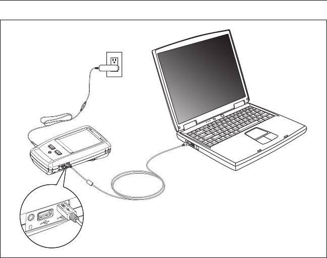
Chapter 13: Maintenance
Update the Software
245
BV46.EPS
Figure 92. How to Connect the Tester to a PC
Micro-AB
USB port
Type A
USB port
AC
adapter

Versiv 2 Cabling Certification Product Family
Users Manual
246
Use an Updated Main Tester to Update Other Testers
1Turn on both testers and connect the AC adapters to both
testers.
2Use the USB cable provided to connect the updated main unit
to the remote or to another main. See Figure 93.
3Follow the instructions shown on the display of the updated
main unit.
Note
If a remote has newer software than the main
unit, the main unit can install the older software
in the remote so that you can use the two units
together. The remote cannot install the newer
software in the main unit.
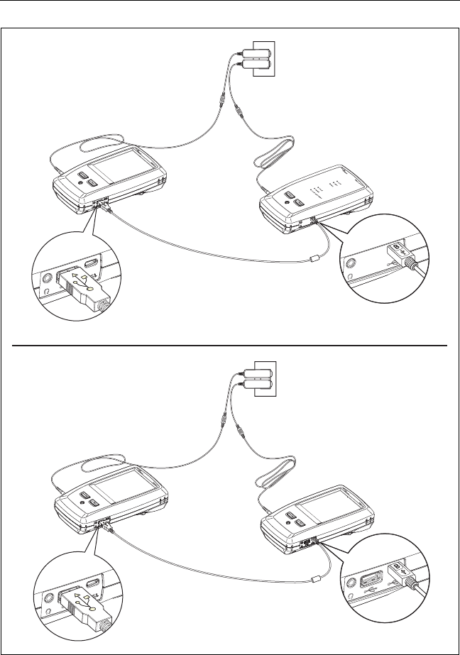
Chapter 13: Maintenance
Update the Software
247
BV116.EPS
Figure 93. How to Connect Units Together to Update the Software
Type A
USB port
Micro-AB
USB port
Type A
USB port
Micro-AB
USB port
Updated
main tester
Main tester
Updated
main tester
Remote
AC
adapters
AC
adapters

Versiv 2 Cabling Certification Product Family
Users Manual
248
Use LinkWare Live to Update the Software
1For a wired internet connection: Use an appropriate cable to
connect the tester’s RJ45 Ethernet port to a network port.
2On the home screen, tap the SYNC icon.
3For a wireless network, if the network selection screen shows,
connect to a network:
a. Select a network.
b. Enter security information.
c. Go back to the previous screen, then tap CONNECT.
d. Go back to the home screen, then tap SYNC.
4On the LWL SIGN IN screen, enter the ID and password for
your LinkWare Live account, then tap SIGN IN.
5If a Versiv software update is available, the tester shows a
message. Tap YES to install new software in your tester.
6The tester reboots when the update is completed.
7To install the update in a remote or another main tester, use
the USB cable provided to connect the updated main tester to
the other tester. See Figure 93.
8Follow the instructions shown on the display of the updated
main tester.
Update the Software in a Module
To update the software in a module, attach it to a main or remote
Versiv unit that has the latest software. The tester automatically
installs the software in the module.

Chapter 13: Maintenance
Extend the Life of the Battery
249
Extend the Life of the Battery
WWarningX
To prevent possible fire, electric shock, or personal
injury, read the warnings about the rechargeable
battery under “WarningX” on page 5.
Do not frequently let the battery discharge completely.
Do not keep the battery at temperatures below -20 oC (-4 oF)
or above +50 oC (+122 oF) for periods longer than one week.
Before you put a battery into storage, charge it to
approximately 50 % of full charge.
Store the Tester
Before you store a tester or an extra battery for a long period,
charge the battery to approximately 50 % of full charge. The
discharge rate of the battery is 5 % to 10 % each month.
Check the battery every 4 months and charge it if necessary.
Keep a battery attached to the tester during storage. If you
remove the battery for more than approximately 24 hours,
the tester will not keep the correct time and date.
Storage temperature: -22 °F to +140 °F (-30 °C to +60 °C)
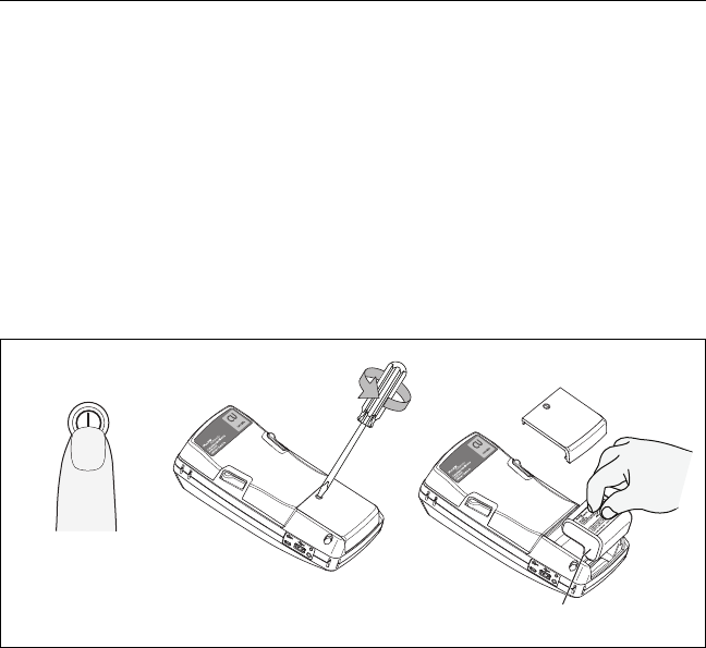
Versiv 2 Cabling Certification Product Family
Users Manual
250
Remove the Battery
Figure 94 shows how to remove the battery.
Notes
If you remove the battery and do not connect the
AC adapter, the clock keeps the current date and
time for a minimum of 24 hours.
The screw does not come out of the battery door.
GPU21.EPS
Figure 94. How to Remove the Battery
If the Tester Does Not Operate as Usual
If the tester does not operate as usual or if it shows an unusual
message, see Table 9 for possible explanations and solutions to
some conditions that can occur.
If the condition continues, contact Fluke Networks for assistance,
or search the Fluke Networks Knowledge Base for a solution.
If you contact Fluke Networks, have available the serial number,
software and hardware versions, and calibration date for the
tester, if possible. To see this information, tap the TOOLS icon on
the home screen, then tap Version Information.
A
BC
Model VERSIV-BATTERY
OFF

Chapter 13: Maintenance
Options and Accessories
251
You can also use LinkWare PC software to upload the system log
from the tester. This file contains information that can possibly
help Fluke Networks find a solution to an unusual problem.
Options and Accessories
For a complete list of options and accessories go to the Fluke
Networks website at www.flukenetworks.com.
To order options and accessories, contact an authorized Fluke
Networks distributor.
Table 9. Possible Solutions for Unusual Behavior
The touchscreen or the keys do not respond.
Press and hold until the tester turns off. Then turn on the tester. If the
problem continues, install the latest version of software in the tester.
The tester will not turn on even though the battery is charged.
The safety switch or the fuse in the battery is possibly open. Wait a few
seconds, then try again. If the tester does not turn on, the battery is possibly
bad and must be replaced. The tester can operate on AC power if the
battery does not operate.
Test results appear to be incorrect.
The tester possibly has incorrect settings. Make sure you selected the correct
cable type and test limit.

Versiv 2 Cabling Certification Product Family
Users Manual
252

253
Appendix A: Reference Method
Names
Industry standards use different names for the three reference
methods. Tables A-1 and A-2 show the names used in this manual
and by four common standards.
Table A-1. Reference Method Names fore TIA/EIA Standards
Link End
Connections
Included in Loss
Results
Method
Name in This
Manual
TIA-526-14B
(multimode)
TIA/EIA-526-7
(singlemode)
2 connections 1 Jumper One-Cord
Reference
Method
(was Method B)
Method A.1
1 connection 2 Jumper Two-Cord
Reference
Method
(was Method A)
Method A.2
None 3 Jumper Three-Cord
Reference
Method
(was Method C)
Method A.3

Versiv 2 Cabling Certification Product Family
Users Manual
254
Table A-2. Reference Method Names for IEC Standards
Link End
Connections
Included in Loss
Results
Method
Name in This
Manual
IEC 61280-4-1
(multimode)
IEC 61280-4-2
(singlemode)
2 connections 1 Jumper One-Cord
Reference
Method
(was Method 2)
One-Cord
Reference Method
(was Method A1)
1 connection 2 Jumper Two-Cord
Reference
Method
(was Method 1)
Two-Cord
Reference Method
(was Method A2)
None 3 Jumper Three-Cord
Reference
Method
(was Method 3)
Three-Cord
Reference Method
(was Method A3)
255
Appendix B: Modified 1 Jumper
Reference Method
This Appendix shows modified reference and test connections
that give 1 jumper results. Use these connections if you need 1
jumper results, but do not have the correct connector adapters to
connect the CertiFiber Pro modules’ output ports to the link. This
method lets you keep the test reference cords connected to the
module’s output ports when you connect the modules to the link.
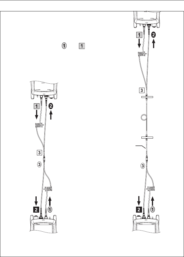
Versiv 2 Cabling Certification Product Family
Users Manual
256
BV139.EPS
Figure B-1. Modified 1 Jumper Reference Method for
Smart Remote Mode
WCaution
Do not disconnect the
outputs ( and ) after
you set the reference.
Short MT-RJ (no pins)
to MT-RJ (pinned)
test reference cord
(0.3 m or less.
Fiber Link Test
Reference
Mandrel*
Mandrel*
*Use mandrels only with multimode modules.