Fortress Technologies ES820 The ES820 is a dual radio access point/bridge. It provides secure connectivity through multiple Ethernet ports and two 802.11 a/b/g radios in a ruggedized enclosure. It provides secure, fixed or mobile communications for harsh environments. User Manual GUI Guide
Fortress Technologies, Inc. The ES820 is a dual radio access point/bridge. It provides secure connectivity through multiple Ethernet ports and two 802.11 a/b/g radios in a ruggedized enclosure. It provides secure, fixed or mobile communications for harsh environments. GUI Guide
Contents
GUI Guide

Fortress Security System
Secure Wireless Bridge
and Security Controller
Software GUI Guide
www.fortresstech.com
© 2010 Fortress Technologies

Bridge GUI Guide
i
009-00035-00v5.4r1
Fortress Bridge and Controller version 5.4 Software GUI Guide [rev.1]
Copyright © 2010 Fortress Technologies, Inc. All rights reserved.
This document contains proprietary information protected by copyright. No part of this
document may be reproduced or transmitted in any form or by any means, electronic or
mechanical, without written permission of Fortress Technologies, 4023 Tampa Road, Suite
2200, Oldsmar, FL 34677, except as specified in the Product Warranty and License Terms.
FORTRESS TECHNOLOGIES, INC., MAKES NO WARRANTY OF ANY KIND WITH
REGARD TO THIS MATERIAL, INCLUDING BUT NOT LIMITED TO THE IMPLIED
WARRANTIES OF MERCHANTABILITY AND FITNESS FOR A PARTICULAR PURPOSE.
FORTRESS TECHNOLOGIES, INC. SHALL NOT BE LIABLE FOR ERRORS
CONTAINED HEREIN OR FOR INCIDENTAL OR CONSEQUENTIAL DAMAGES IN
CONNECTION WITH THE FURNISHING, PERFORMANCE OR USE OF THIS
MATERIAL. THE INFORMATION IN THIS DOCUMENT IS SUBJECT TO CHANGE
WITHOUT NOTICE.
The Fortress Technologies and AirFortress logos and AirFortress and are registered
trademarks; Multi-Factor Authentication, Unified Security Model, Wireless Link Layer
Security and Three Factor Authentication (TFA) are trademarks of Fortress Technologies,
Inc. The technology behind Wireless Link Layer Security™ enjoys U.S. and international
patent protection under patent number 5,757,924.
Portions of this software are covered by the GNU General Public License (GPL) Copyright
© 1989, 1991 Free Software Foundation, Inc,. 59 Temple Place, Suite 330, Boston, MA
02111-1307 USA.
To receive a complete machine-readable copy of the corresponding source code on CD,
send $10 (to cover the costs of production and mailing) to: Fortress Technologies; 4023
Tampa Road, suite 2200; Oldsmar, FL 34677-3216. Please be sure to include a copy of
your Fortress Technologies invoice and a valid “ship to” address.
This product includes cryptographic software written by Eric Young (eay@cryptsoft.com).
This product includes software written by Tim Hudson (tjh@cryptsoft.com).
Copyright © 1995-1998 Eric Young (eay@cryptsoft.com) All rights reserved.
This package is an SSL implementation written by Eric Young (eay@cryptsoft.com). The
implementation was written so as to conform with Netscape’s SSL.
THIS SOFTWARE IS PROVIDED BY ERIC YOUNG ``AS IS'' AND ANY EXPRESS OR
IMPLIED WARRANTIES, INCLUDING, BUT NOT LIMITED TO, THE IMPLIED
WARRANTIES OF MERCHANTABILITY AND FITNESS FOR A PARTICULAR PURPOSE
ARE DISCLAIMED. IN NO EVENT SHALL THE AUTHOR OR CONTRIBUTORS BE
LIABLE FOR ANY DIRECT, INDIRECT, INCIDENTAL, SPECIAL, EXEMPLARY, OR
CONSEQUENTIAL DAMAGES (INCLUDING, BUT NOT LIMITED TO, PROCUREMENT
OF SUBSTITUTE GOODS OR SERVICES; LOSS OF USE, DATA, OR PROFITS; OR
BUSINESS INTERRUPTION) HOWEVER CAUSED AND ON ANY THEORY OF
LIABILITY, WHETHER IN CONTRACT, STRICT LIABILITY, OR TORT (INCLUDING
NEGLIGENCE OR OTHERWISE) ARISING IN ANY WAY OUT OF THE USE OF THIS
SOFTWARE, EVEN IF ADVISED OF THE POSSIBILITY OF SUCH DAMAGE.
Atheros, the Atheros logo, Atheros Driven, Driving the wireless future, Super G and Super
AG are all registered trademarks of Atheros Communications. ROCm, JumpStart for
Wireless, Atheros XR, Wake-on-Wireless, Wake-on-Theft, and FastFrames, are all
trademarks of Atheros Communications, Inc.
This product uses Dynamic Host Control Protocol, Copyright © 2004–2010 by Internet
Software Consortium, Inc. Copyright © 1995–2003 by Internet Software Consortium. All
rights reserved.
This product includes software developed by the OpenSSL Project for use in the OpenSSL
Toolkit. (http://www.openssl.org/)
Copyright © 1998-2007 The OpenSSL Project. All rights reserved.THIS SOFTWARE IS
PROVIDED BY THE OpenSSL PROJECT ``AS IS'' AND ANY EXPRESSED OR IMPLIED
WARRANTIES, INCLUDING, BUT NOT LIMITED TO, THE IMPLIED WARRANTIES OF
MERCHANTABILITY AND FITNESS FOR A PARTICULAR PURPOSE ARE
DISCLAIMED. IN NO EVENT SHALL THE OpenSSL PROJECT OR ITS CONTRIBUTORS

Bridge GUI Guide
ii
BE LIABLE FOR ANY DIRECT, INDIRECT, INCIDENTAL, SPECIAL, EXEMPLARY, OR
CONSEQUENTIAL DAMAGES (INCLUDING, BUT NOT LIMITED TO, PROCUREMENT
OF SUBSTITUTE GOODS OR SERVICES; LOSS OF USE, DATA, OR PROFITS; OR
BUSINESS INTERRUPTION) HOWEVER CAUSED AND ON ANY THEORY OF
LIABILITY, WHETHER IN CONTRACT, STRICT LIABILITY, OR TORT (INCLUDING
NEGLIGENCE OR OTHERWISE) ARISING IN ANY WAY OUT OF THE USE OF THIS
SOFTWARE, EVEN IF ADVISED OF THE POSSIBILITY OF SUCH DAMAGE.
This product uses Net-SNMP Copyright © 1989, 1991, 1992 by Carnegie Mellon
University, Derivative Work - 1996, 1998-2000. Copyright © 1996, 1998-2000 The Regents
of the University of California. All rights reserved. Copyright © 2001-2003, Cambridge
Broadband Ltd. All rights reserved. Copyright © 2003 Sun Microsystems, Inc. All rights
reserved. Copyright © 2001-2006, Networks Associates Technology, Inc. All rights
reserved. Center of Beijing University of Posts and Telecommunications. All rights
reserved.
Licensed under the Apache License, Version 2.0 (the "License"); you may not use this file
except in compliance with the License. You may obtain a copy of the License at http://
www.apache.org/licenses/LICENSE-2.0. Unless required by applicable law or agreed to in
writing, software distributed under the License is distributed on an "AS IS" BASIS,
WITHOUT WARRANTIES OR CONDITIONS OF ANY KIND, either express or implied.
See the License for the specific language governing permissions and limitations under the
License.
Microsoft and Windows are registered trademarks of the Microsoft Corporation.
Firefox is a trademark of the Mozilla Foundation.
SSH is a trademark of SSH Communication Security.
All other trademarks mentioned in this document are the property of their respective
owners.
End User License Agreement (EULA)
IMPORTANT; PLEASE READ THIS END USER LICENSE AGREEMENT CAREFULLY.
DOWNLOADING, INSTALLING OR USING FORTRESS TECHNOLOGIES SOFTWARE
CONSTITUTES ACCEPTANCE OF THIS AGREEMENT.
FORTRESS TECHNOLOGIES, INC., WILL LICENSE ITS SOFTWARE TO YOU THE
CUSTOMER (END USER) ONLY UPON THE CONDITION THAT YOU ACCEPT ALL OF
THE TERMS CONTAINED IN THIS END USER LICENSE AGREEMENT. THE ACT OF
DOWNLOADING, INSTALLING, OR USING FORTRESS SOFTWARE, BINDS YOU AND
THE BUSINESS THAT YOU REPRESENT (COLLECTIVELY, “CUSTOMER”) TO THE
AGREEMENT.
License
Fortress grants to Customer (“Licensee”) a non-exclusive and non-transferable right to use
the Fortress Software Product (“Software”) described in the Fortress Product Description
for which Customer has paid any required license fees and subject to the use rights and
limitations in this Agreement. Unless otherwise agreed to in writing, use of the Software is
limited to the number of authorized users for which Licensee has purchased the right to the
use of the software. Software is authorized for installation on any Fortress approved
device. “Software” includes computer program(s) and any documentation (whether
contained in user manuals, technical manuals, training materials, specifications, etc.) that
is included with the software (including CD-ROM, or on-line). Software is authorized for
installation on a single use computing device such as Fortress hardware platform,
computer, laptop, PDA or any other computing device. Software is not licensed for
installation or embedded use on any other system(s) controlling access to a secondary
network of devices or securing access for any separate computing devices. Software
contains proprietary technology of Fortress or third parties. No ownership in or title to the
Software is transferred. Software is protected by copyright laws and international treaties.
Customer may be required to input a software license key to initialize the software
installation process.

Bridge GUI Guide
iii
Customer may make backup or archival copies of Software and use Software on a backup
processor temporarily in the event of a processor malfunction. Any full or partial copy of
Software must include all copyright and other proprietary notices which appear on or in the
Software. Control functions may be installed and enabled. Customer may not modify
control utilities. Customer may not disclose or make available Software to any other party
or permit others to use it except Customer's employees and agents who use it on
Customer's behalf and who have agreed to these license terms. Customer may not transfer
the software to another party except with Fortress' written permission. Customer agrees
not to reverse engineer, decompile, or disassemble the Software. Customer shall maintain
adequate records matching the use of Software to license grants and shall make the
records available to Fortress or the third party developer or owner of the Software on
reasonable notice. Fortress may terminate any license granted hereunder if Customer
breaches any license term. Upon termination of the Agreement, Customer shall destroy or
return to Fortress all copies of Software.
General Limitations
This is a License for the use of Fortress Software Product and documentation; it is not a
transfer of title. Fortress retains ownership of all copies of the Software and
Documentation. Customer acknowledges that Fortress or Fortress Solution Provider trade
secrets are contained within the Software and Documentation. Except as otherwise
expressly provided under the Agreement, Customer shall have no right and Customer
specifically agrees not to:
i.Transfer, assign or sublicense its license rights to any other person or entity and
Customer acknowledges that any attempt to transfer, assign or sublicense shall “void” the
license;
ii.Make modifications to or adapt the Software or create a derivative work based on the
Software, or permit third parties to do the same;
iii.Reverse engineer, decompile, or disassemble the Software to a human-readable form,
except to the extent otherwise expressly permitted under applicable law notwithstanding
this restriction and;
iv.Disclose, provide, or otherwise make available trade secrets contained within the
Software and Documentation in any form to any third party without the prior written consent
of Fortress Technologies. Customer shall implement reasonable security measures to
protect such trade secrets.
Software, Upgrades and Additional Copies
For purposes of the Agreement, “Software” shall include computer programs, including
firmware, as provided to Customer by Fortress or a Fortress Solution Provider, and any (a)
bug fixes, (b) maintenance releases, (c) minor and major upgrades as deemed to be
included under this agreement by Fortress or backup copies of any of the foregoing.
NOTWITHSTANDING ANY OTHER PROVISION OF THE AGREEMENT:
i.CUSTOMER HAS NO LICENSE OR RIGHT TO MAKE OR USE ANY ADDITIONAL
COPIES OR UPGRADES UNLESS CUSTOMER, AT THE TIME OF MAKING OR
ACQUIRING SUCH COPY OR UPGRADE, ALREADY HOLDS A VALID LICENSE TO
THE ORIGINAL SOFTWARE AND HAS PAID THE APPLICABLE FEE FOR THE
UPGRADE OR ADDITIONAL COPIES;
ii.USE OF UPGRADES IS LIMITED TO FORTRESS EQUIPMENT FOR WHICH
CUSTOMER IS THE ORIGINAL END USER CUSTOMER OR LESSEE OR OTHERWISE
HOLDS A VALID LICENSE TO USE THE SOFTWARE WHICH IS BEING UPGRADED;
AND;
iii.THE MAKING AND USE OF ADDITIONAL COPIES IS LIMITED TO NECESSARY
BACKUP PURPOSES ONLY.
Proprietary Notices
All copyright and other proprietary notices on all copies of the Software shall be maintained
and reproduced by the Customer in the same manner that such copyright and other
proprietary notices are included on the Software. Customer shall not make any copies or
duplicates of any Software without the prior written permission of Fortress; except as
expressly authorized in the Agreement.

Bridge GUI Guide
iv
Term and Termination
This Agreement and License shall remain in effect until terminated through one of the
following circumstances:
i.Agreement and License may be terminated by the Customer at any time by destroying all
copies of the Software and any Documentation.
ii.Agreement and License may be terminated by Fortress due to Customer non-compliance
with any provision of the Agreement.
Upon termination by either the Customer or Fortress, the Customer shall destroy or return
to Fortress all copies of Software and Documentation in its possession or control. All
limitations of liability, disclaimers, restrictions of warranty, and all confidentiality obligations
of Customer shall survive termination of this Agreement. Also, the provisions set-forth in
the sections titled “U.S. Government Customers” and “General Terms Applicable to the
Limited Warranty Statement and End User License Agreement” shall survive termination of
the Agreement.
Customer Records
Fortress and its independent accountants reserve the right to conduct an audit of Customer
records to verify compliance with this agreement. Customer grants to Fortress and its
independent accountants access to its books, records and accounts during Customer's
normal business hours in support of such an audit. Customer shall pay to Fortress the
appropriate license fees, plus the reasonable cost of conducting the audit should an audit
disclose non-compliance with this Agreement.
Export Restrictions
Customer acknowledges that the laws and regulations of the United States restrict the
export and re-export of certain commodities and technical data of United States origin,
including the Product, Software and the Documentation, in any medium. Customer will not
knowingly, without prior authorization if required, export or re-export the Product, Software
or the Documentation in any medium without the appropriate United States and foreign
government licenses. The transfer or export of the software outside the U.S. may require a
license from the Bureau of Industry and Security. For questions call BIS at 202-482-4811.
U.S Government Customers
The Software and associated documentation were developed at private expense and are
delivered and licensed as “commercial computer software” as defined in DFARS 252.227-
7013, DFARS 252.227-7014, or DFARS 252.227-7015 as a “commercial item” as defined
in FAR 2.101(a), or as “Restricted computer software” as defined in FAR 52.227-19. All
other technical data, including manuals or instructional materials, are provided with
“Limited Rights” as defined in DFAR 252.227-7013 (a) (15), or FAR 52.227-14 (a) and in
Alternative II (JUN 1987) of that clause, as applicable.
Limited Warranty
The warranties provided by Fortress in this Statement of Limited Warranty apply only to
Fortress Products purchased from Fortress or from a Fortress Solution Provider for internal
use on Customer's computer network. “Product” means a Fortress software product,
upgrades, or firmware, or any combination thereof. The term “Product” also includes
Fortress software programs, whether pre-loaded with the Fortress hardware Product,
installed subsequently or otherwise. Unless Fortress specifies otherwise, the following
warranties apply only in the country where Customer acquires the Product. Nothing in this
Statement of Warranty affects any statutory rights of consumers that cannot be waived or
limited by contract.
Customer is responsible for determining the suitability of the Products in Customer's
network environment. Unless otherwise agreed, Customer is responsible for the Product's
installation, set-up, configuration, and for password and digital signature management.
Fortress warrants the Products will conform to the published specifications and will be free
of defects in materials and workmanship. Customer must notify Fortress within the
specified warranty period of any claim of such defect. The warranty period for software is
one (1) year commencing from the ship date to Customer [and in the case of resale by a
Fortress Solution Provider, commencing not more than (90) days after original shipment by

Bridge GUI Guide
v
Fortress]. Date of shipment is established per the shipping document (packing list) for the
Product that is shipped from Fortress location.
Customer shall provide Fortress with access to the Product to enable Fortress to diagnose
and correct any errors or defects. If the Product is found defective by Fortress, Fortress'
sole obligation under this warranty is to remedy such defect at Fortress' option through
repair, upgrade or replacement of product. Services and support provided to diagnose a
reported issue with a Fortress Product, which is then determined not to be the root cause of
the issue, may at Fortress’ option be billed at the standard time and material rates.
Warranty Exclusions
The warranty does not cover Fortress Hardware Product or Software or any other
equipment upon which the Software is authorized by Fortress or its suppliers or licensors,
which (a) has been damaged through abuse or negligence or by accident, (b) has been
altered except by an authorized Fortress representative, (c) has been subjected to
abnormal physical or electrical stress (i.e., lightning strike) or abnormal environmental
conditions, (d) has been lost or damaged in transit, or (e) has not been installed, operated,
repaired or maintained in accordance with instructions provided by Fortress.
The warranty is voided by removing any tamper evidence security sticker or marking
except as performed by a Fortress authorized service technician.
Fortress does not warrant uninterrupted or error-free operation of any Products or third
party software, including public domain software which may have been incorporated into
the Fortress Product.
Fortress will bear no responsibility with respect to any defect or deficiency resulting from
accidents, misuse, neglect, modifications, or deficiencies in power or operating
environment.
Unless specified otherwise, Fortress does not warrant or support non-Fortress products. If
any service or support is rendered such support is provided WITHOUT WARRANTIES OF
ANY KIND.
DISCLAIMER OF WARRANTY
THE WARRANTIES HEREIN ARE SOLE AND EXCLUSIVE, AND NO OTHER
WARRANTY, WHETHER WRITTEN OR ORAL, IS EXPRESSED OR IMPLIED. TO THE
EXTENT PERMITTED BY LAW, FORTRESS SPECIFICALLY DISCLAIMS THE IMPLIED
WARRANTIES OF MERCHANTABILITY, FITNESS FOR A PARTICULAR PURPOSE,
TITLE AND NONINFRINGEMENT.
General Terms Applicable to the Limited Warranty and End User License Agreement
Disclaimer of Liabilities
THE FOREGOING WARRANTIES ARE THE EXCLUSIVE WARRANTIES AND REPLACE
ALL OTHER WARRANTIES OR CONDITIONS, EXPRESS OR IMPLIED, INCLUDING,
BUT NOT LIMITED TO, THE IMPLIED WARRANTIES OR CONDITIONS OF
MERCHANTABILITY AND FITNESS FOR A PARTICULAR PURPOSE. FORTRESS
SHALL HAVE NO LIABILITY FOR CONSEQUENTIAL, EXEMPLARY, OR INCIDENTAL
DAMAGES EVEN IF IT HAS BEEN ADVISED OF THE POSSIBILITY OF SUCH
DAMAGES. THE STATED LIMITED WARRANTY IS IN LIEU OF ALL LIABILITIES OR
OBLIGATIONS OF FORTRESS FOR DAMAGES ARISING OUT OF OR IN CONNECTION
WITH THE DELIVERY, USE, OR PERFORMANCE OF THE PRODUCTS (HARDWARE
AND SOFTWARE). THESE WARRANTIES GIVE SPECIFIC LEGAL RIGHTS AND
CUSTOMER MAY ALSO HAVE OTHER RIGHTS WHICH VARY FROM JURISDICTION
TO JURISDICTION. SOME JURISDICTIONS DO NOT ALLOW THE EXCLUSION OR
LIMITATION OF EXPRESS OR IMPLIED WARRANTIES, SO THE ABOVE EXCLUSION
OR LIMITATION MAY NOT APPLY TO YOU. IN THAT EVENT, SUCH WARRANTIES ARE
LIMITED IN DURATION TO THE WARRANTY PERIOD. NO WARRANTIES APPLY
AFTER THAT PERIOD.
Product Warranty and License Terms
Indemnification
Fortress will defend any action brought against Customer based on a claim that any
Fortress Product infringes any U.S. patents or copyrights excluding third party software,
provided that Fortress is immediately notified in writing and Fortress has the right to control

Bridge GUI Guide
vi
the defense of all such claims, lawsuits, and other proceedings. If, as a result of any claim
of infringement against any U.S. patent or copyright, Fortress is enjoined from using the
Product, or if Fortress believes the Product is likely to become the subject of a claim of
infringement, Fortress at its option and expense may procure the right for Customer to
continue to use the Product, or replace or modify the Product so as to make it non-
infringing. If neither of these two options is reasonably practicable, Fortress may
discontinue the license granted herein on one month's written notice and refund to
Licensee the unamortized portion of the license fees hereunder. The depreciation shall be
an equal amount per year over the life of the Product as established by Fortress. The
foregoing states the entire liability of Fortress and the sole and exclusive remedy of the
Customer with respect to infringement of third party intellectual property.
Limitation of Liability
Circumstances may arise where, because of a default on Fortress' part or other liability,
Customer is entitled to recover damages from Fortress. In each such instance, regardless
of the basis on which you are entitled to claim damages from Fortress (including
fundamental breach, negligence, misrepresentation, or other contract or tort claim),
Fortress is liable for no more than damages for bodily injury (including death) and damage
to real property and tangible personal property, and the amount of any other actual direct
damages, up to either U.S. $25,000 (or equivalent in local currency) or the charges (if
recurring, 12 months' charges apply) for the Product that is the subject of the claim,
whichever is less. This limit also applies to Fortress' Solution Providers. It is the maximum
for which Fortress and its Solution Providers are collectively responsible.
UNDER NO CIRCUMSTANCES IS FORTRESS LIABLE FOR ANY OF THE FOLLOWING:
1) THIRD-PARTY CLAIMS AGAINST YOU FOR DAMAGES,
2) LOSS OF, OR DAMAGE TO, YOUR RECORDS OR DATA, OR
3) SPECIAL, INCIDENTAL, OR INDIRECT DAMAGES OR FOR ANY ECONOMIC
CONSEQUENTIAL DAMAGES (INCLUDING LOST PROFITS OR SAVINGS), EVEN IF
FORTRESS OR ITS SOLUTION PROVIDER IS INFORMED OF THEIR POSSIBILITY.
SOME JURISDICTIONS DO NOT ALLOW THE EXCLUSION OR LIMITATION OF
INCIDENTAL OR CONSEQUENTIAL DAMAGES, SO THE ABOVE LIMITATION OR
EXCLUSION MAY NOT APPLY TO CUSTOMER.
Telephone Support
During the warranty period, Fortress or its Solution Provider will provide a reasonable
amount of telephone consultation to the Customer. This support shall include assistance in
connection with the installation and routine operation of the Product, but does not include
network troubleshooting, security consultation, design and other services outside of the
scope of routine Product operation. Warranty services for the Products shall be available
during Fortress' normal U.S. (EST) business days and hours.
Extended Warranty Service
If the Customer purchases an extended warranty service agreement with Fortress, service
will be provided in accordance to said agreement's terms and conditions.
Access and Service
Customer must provide Fortress or Solution Provider with access to the Product to enable
Fortress or Solution Provider to provide the service. Access may include access via the
Internet, on-site access or Customer shall be responsible for returning the Product to
Fortress or Solution Provider. Fortress or Solution Provider will notify the Customer to
obtain authorization to perform any repairs.
If, during the warranty period, as established by the date of shipment [and in the case of
resale by a Fortress Solution Provider, commencing not more than (90) days after original
shipment by Fortress], the Customer finds any significant defect in materials and
workmanship under normal use and operating conditions, the Customer shall notify
Fortress Customer Service in accordance with the Fortress Service Policies in effect at that
time which can be located on the Fortress web site: www.fortresstech.com.
EULA Addendum for Products Containing 4.4 GHz Military Band Radio(s)
This product contains one or more radios which operate in the 4.400GHz - 4.750GHz
range.

Bridge GUI Guide
vii
This frequency range is owned and operated by the U.S. Department of Defense and its
use is restricted to users with proper authorization. By accepting this agreement, user
acknowledges that proper authorization to operate in this frequency has been obtained and
user accepts full responsibility for any unauthorized use. User agrees to indemnify and hold
harmless Fortress Technologies, Inc. from any fines, costs or expenses resulting from or
associated with unauthorized use of this frequency range.
This EULA Addendum does not apply to Fortress products that do not contain 4.4 GHz
radios.

Bridge GUI Guide: Table of Contents
viii
Table of Contents
1
Introduction 1
This Document . . . . . . . . . . . . . . . . . . . . . . . . . . . . . . . . . . . . . . . . . . . 1
Related Documents . . . . . . . . . . . . . . . . . . . . . . . . . . . . . . . . . . . . . . . . . . . . . . . . . 1
Network Security Overview . . . . . . . . . . . . . . . . . . . . . . . . . . . . . . . . . 2
Fortress Security Systems . . . . . . . . . . . . . . . . . . . . . . . . . . . . . . . . . . 2
Fortress Bridges and Controllers . . . . . . . . . . . . . . . . . . . . . . . . . . . . . . . . . . . . . . 2
ES-Series Model Numbers . . . . . . . . . . . . . . . . . . . . . . . . . . . . . . . . . . . . . . . . . . . . . . .3
Fortress Bridge Management . . . . . . . . . . . . . . . . . . . . . . . . . . . . . . . . . . . . . . . . . . . . .4
Fortress Secure Client Software . . . . . . . . . . . . . . . . . . . . . . . . . . . . . . . . . . . . . . . 5
Network Deployment Options . . . . . . . . . . . . . . . . . . . . . . . . . . . . . . . 5
FastPath Mesh Network Deployments . . . . . . . . . . . . . . . . . . . . . . . . . . . . . . . . . . 5
Isolated FastPath Mesh Networks . . . . . . . . . . . . . . . . . . . . . . . . . . . . . . . . . . . . . . . . .6
Network-Attached FastPath Mesh Networks . . . . . . . . . . . . . . . . . . . . . . . . . . . . . . . . .7
Separating and Rejoining in FastPath Mesh Networks . . . . . . . . . . . . . . . . . . . . . . . . .9
Bridging Loops in FastPath Mesh Networks . . . . . . . . . . . . . . . . . . . . . . . . . . . . . . . . . 10
Traffic Duplication in FastPath Mesh Networks . . . . . . . . . . . . . . . . . . . . . . . . . . . . . . 11
STP Mesh Network Deployments . . . . . . . . . . . . . . . . . . . . . . . . . . . . . . . . . . . . . .12
Point-to-Point Bridging Deployments . . . . . . . . . . . . . . . . . . . . . . . . . . . . . . . . . . .14
Wireless Client ES210 Bridge Deployments . . . . . . . . . . . . . . . . . . . . . . . . . . . . . .14
Compatibility . . . . . . . . . . . . . . . . . . . . . . . . . . . . . . . . . . . . . . . . . . . .15
2
Bridge GUI and Administrative Access 16
Bridge GUI . . . . . . . . . . . . . . . . . . . . . . . . . . . . . . . . . . . . . . . . . . . . . .16
System Requirements . . . . . . . . . . . . . . . . . . . . . . . . . . . . . . . . . . . . . . . . . . . . . . .16
Bridge GUI Security . . . . . . . . . . . . . . . . . . . . . . . . . . . . . . . . . . . . . . . . . . . . . . . .16
Logging On . . . . . . . . . . . . . . . . . . . . . . . . . . . . . . . . . . . . . . . . . . . . . . . . . . . . . . .16
Using Bridge GUI Views . . . . . . . . . . . . . . . . . . . . . . . . . . . . . . . . . . . . . . . . . . . . .18
Accessing Bridge GUI Help . . . . . . . . . . . . . . . . . . . . . . . . . . . . . . . . . . . . . . . . . . .19
Logging Off . . . . . . . . . . . . . . . . . . . . . . . . . . . . . . . . . . . . . . . . . . . . . . . . . . . . . . .19

Bridge GUI Guide: Table of Contents
ix
Administrative Accounts and Access . . . . . . . . . . . . . . . . . . . . . . . . . .19
Global Administrator Settings . . . . . . . . . . . . . . . . . . . . . . . . . . . . . . . . . . . . . . . . .20
Maximum Failed Logon Attempts . . . . . . . . . . . . . . . . . . . . . . . . . . . . . . . . . . . . . . . . . 20
Failed Logon Timeout . . . . . . . . . . . . . . . . . . . . . . . . . . . . . . . . . . . . . . . . . . . . . . . . . . 21
Lockout Behavior . . . . . . . . . . . . . . . . . . . . . . . . . . . . . . . . . . . . . . . . . . . . . . . . . . . . . 21
Session Idle Timeout . . . . . . . . . . . . . . . . . . . . . . . . . . . . . . . . . . . . . . . . . . . . . . . . . . 21
Show Previous Logon . . . . . . . . . . . . . . . . . . . . . . . . . . . . . . . . . . . . . . . . . . . . . . . . . . 21
Authentication Method and Failback . . . . . . . . . . . . . . . . . . . . . . . . . . . . . . . . . . . . . . 22
Password Expiration . . . . . . . . . . . . . . . . . . . . . . . . . . . . . . . . . . . . . . . . . . . . . . . . . . . 25
Password Requirements . . . . . . . . . . . . . . . . . . . . . . . . . . . . . . . . . . . . . . . . . . . . . . . 26
System Messages . . . . . . . . . . . . . . . . . . . . . . . . . . . . . . . . . . . . . . . . . . . . . . . . . . . . 28
Individual Administrator Accounts . . . . . . . . . . . . . . . . . . . . . . . . . . . . . . . . . . . . . .30
Administrator User Names . . . . . . . . . . . . . . . . . . . . . . . . . . . . . . . . . . . . . . . . . . . . . . 31
Account Administrative State . . . . . . . . . . . . . . . . . . . . . . . . . . . . . . . . . . . . . . . . . . . . 31
Administrative Role . . . . . . . . . . . . . . . . . . . . . . . . . . . . . . . . . . . . . . . . . . . . . . . . . . . . 31
Administrator Audit Requirement . . . . . . . . . . . . . . . . . . . . . . . . . . . . . . . . . . . . . . . . . 32
Administrator Full Name and Description . . . . . . . . . . . . . . . . . . . . . . . . . . . . . . . . . . . 32
Administrator Interface Permissions . . . . . . . . . . . . . . . . . . . . . . . . . . . . . . . . . . . . . . . 32
Administrator Passwords and Password Controls . . . . . . . . . . . . . . . . . . . . . . . . . . . . 33
Adding Administrative Accounts . . . . . . . . . . . . . . . . . . . . . . . . . . . . . . . . . . . . . . . . . . 34
Editing Administrative Accounts . . . . . . . . . . . . . . . . . . . . . . . . . . . . . . . . . . . . . . . . . . 37
Deleting Administrative Accounts . . . . . . . . . . . . . . . . . . . . . . . . . . . . . . . . . . . . . . . . . 37
Changing Administrative Passwords . . . . . . . . . . . . . . . . . . . . . . . . . . . . . . . . . . . . . . 38
Unlocking Administrator Accounts . . . . . . . . . . . . . . . . . . . . . . . . . . . . . . . . . . . . . . . . 39
Administrator IP Address Access Control . . . . . . . . . . . . . . . . . . . . . . . . . . . . . . . .39
SNMP Administration . . . . . . . . . . . . . . . . . . . . . . . . . . . . . . . . . . . . . . . . . . . . . . .41
Configuring SNMP v3 . . . . . . . . . . . . . . . . . . . . . . . . . . . . . . . . . . . . . . . . . . . . . . . . . . 42
Configuring SNMP Traps . . . . . . . . . . . . . . . . . . . . . . . . . . . . . . . . . . . . . . . . . . . . . . . 43
3
Network and Radio Configuration 46
Network Interfaces . . . . . . . . . . . . . . . . . . . . . . . . . . . . . . . . . . . . . . . .46
Bridging Configuration . . . . . . . . . . . . . . . . . . . . . . . . . . . . . . . . . . . . .47
FastPath Mesh Bridging . . . . . . . . . . . . . . . . . . . . . . . . . . . . . . . . . . . . . . . . . . . . .48
FastPath Mesh Bridging Mode . . . . . . . . . . . . . . . . . . . . . . . . . . . . . . . . . . . . . . . . . . . 50
Fortress Security . . . . . . . . . . . . . . . . . . . . . . . . . . . . . . . . . . . . . . . . . . . . . . . . . . . . . 50
Mobility Factor . . . . . . . . . . . . . . . . . . . . . . . . . . . . . . . . . . . . . . . . . . . . . . . . . . . . . . . 51
Mesh Subnet ID . . . . . . . . . . . . . . . . . . . . . . . . . . . . . . . . . . . . . . . . . . . . . . . . . . . . . . 51
Network Cost Weighting . . . . . . . . . . . . . . . . . . . . . . . . . . . . . . . . . . . . . . . . . . . . . . . . 51
Neighbor Cost Overrides . . . . . . . . . . . . . . . . . . . . . . . . . . . . . . . . . . . . . . . . . . . . . . . 52
Multicast Group Subscription . . . . . . . . . . . . . . . . . . . . . . . . . . . . . . . . . . . . . . . . . . . . 52
Configuring FastPath Mesh Settings: . . . . . . . . . . . . . . . . . . . . . . . . . . . . . . . . . . . . . . 53
STP Bridging . . . . . . . . . . . . . . . . . . . . . . . . . . . . . . . . . . . . . . . . . . . . . . . . . . . . . .56
Configuring STP Bridging: . . . . . . . . . . . . . . . . . . . . . . . . . . . . . . . . . . . . . . . . . . . . . . 57

Bridge GUI Guide: Table of Contents
x
Radio Settings . . . . . . . . . . . . . . . . . . . . . . . . . . . . . . . . . . . . . . . . . . .57
Advanced Global Radio Settings . . . . . . . . . . . . . . . . . . . . . . . . . . . . . . . . . . . . . .58
Radio Frequency Kill . . . . . . . . . . . . . . . . . . . . . . . . . . . . . . . . . . . . . . . . . . . . . . . . . . 58
Radio Distance Units . . . . . . . . . . . . . . . . . . . . . . . . . . . . . . . . . . . . . . . . . . . . . . . . . . 58
Country of Operation . . . . . . . . . . . . . . . . . . . . . . . . . . . . . . . . . . . . . . . . . . . . . . . . . . 58
Environment Setting . . . . . . . . . . . . . . . . . . . . . . . . . . . . . . . . . . . . . . . . . . . . . . . . . . . 59
Configuring Global Advanced Radio Settings . . . . . . . . . . . . . . . . . . . . . . . . . . . . . . . 60
Individual Radio Settings . . . . . . . . . . . . . . . . . . . . . . . . . . . . . . . . . . . . . . . . . . . . .60
Radio Administrative State . . . . . . . . . . . . . . . . . . . . . . . . . . . . . . . . . . . . . . . . . . . . . . 61
Radio Band . . . . . . . . . . . . . . . . . . . . . . . . . . . . . . . . . . . . . . . . . . . . . . . . . . . . . . . . . . 61
Channel and Channel Width . . . . . . . . . . . . . . . . . . . . . . . . . . . . . . . . . . . . . . . . . . . . . 63
Network Type . . . . . . . . . . . . . . . . . . . . . . . . . . . . . . . . . . . . . . . . . . . . . . . . . . . . . . . . 64
Antenna Gain . . . . . . . . . . . . . . . . . . . . . . . . . . . . . . . . . . . . . . . . . . . . . . . . . . . . . . . . 64
Tx Power Mode and Tx Power Settings . . . . . . . . . . . . . . . . . . . . . . . . . . . . . . . . . . . . 65
Distance . . . . . . . . . . . . . . . . . . . . . . . . . . . . . . . . . . . . . . . . . . . . . . . . . . . . . . . . . . . . 65
Beacon Interval . . . . . . . . . . . . . . . . . . . . . . . . . . . . . . . . . . . . . . . . . . . . . . . . . . . . . . . 66
Short Preamble . . . . . . . . . . . . . . . . . . . . . . . . . . . . . . . . . . . . . . . . . . . . . . . . . . . . . . . 67
Noise Immunity . . . . . . . . . . . . . . . . . . . . . . . . . . . . . . . . . . . . . . . . . . . . . . . . . . . . . . . 67
Configuring Individual Radio Settings: . . . . . . . . . . . . . . . . . . . . . . . . . . . . . . . . . . . . . 67
DFS Operation and Channel Exclusion . . . . . . . . . . . . . . . . . . . . . . . . . . . . . . . . .68
DFS Operation on the Bridge . . . . . . . . . . . . . . . . . . . . . . . . . . . . . . . . . . . . . . . . . . . . 68
Channel Exclusion . . . . . . . . . . . . . . . . . . . . . . . . . . . . . . . . . . . . . . . . . . . . . . . . . . . . 69
Radio BSS Settings . . . . . . . . . . . . . . . . . . . . . . . . . . . . . . . . . . . . . . . . . . . . . . . . .70
BSS Administrative State and Name . . . . . . . . . . . . . . . . . . . . . . . . . . . . . . . . . . . . . . 71
BSS SSID and Advertise SSID . . . . . . . . . . . . . . . . . . . . . . . . . . . . . . . . . . . . . . . . . . . 71
Wireless Bridge and Minimum RSS . . . . . . . . . . . . . . . . . . . . . . . . . . . . . . . . . . . . . . . 72
User Cost Offset and FastPath Mesh Mode . . . . . . . . . . . . . . . . . . . . . . . . . . . . . . . . . 72
BSS Switching Mode and Default VLAN ID . . . . . . . . . . . . . . . . . . . . . . . . . . . . . . . . . 73
BSS G Band Only Setting . . . . . . . . . . . . . . . . . . . . . . . . . . . . . . . . . . . . . . . . . . . . . . . 73
BSS WMM Setting . . . . . . . . . . . . . . . . . . . . . . . . . . . . . . . . . . . . . . . . . . . . . . . . . . . . 74
BSS DTIM Period . . . . . . . . . . . . . . . . . . . . . . . . . . . . . . . . . . . . . . . . . . . . . . . . . . . . . 74
BSS RTS and Fragmentation Thresholds . . . . . . . . . . . . . . . . . . . . . . . . . . . . . . . . . . 75
BSS Unicast Rate Mode and Maximum Rate . . . . . . . . . . . . . . . . . . . . . . . . . . . . . . . . 76
BSS Multicast Rate . . . . . . . . . . . . . . . . . . . . . . . . . . . . . . . . . . . . . . . . . . . . . . . . . . . . 76
BSS Description . . . . . . . . . . . . . . . . . . . . . . . . . . . . . . . . . . . . . . . . . . . . . . . . . . . . . . 77
BSS Fortress Security Setting . . . . . . . . . . . . . . . . . . . . . . . . . . . . . . . . . . . . . . . . . . . 77
BSS Wi-Fi Security Settings . . . . . . . . . . . . . . . . . . . . . . . . . . . . . . . . . . . . . . . . . . . . . 77
Configuring a Radio BSS . . . . . . . . . . . . . . . . . . . . . . . . . . . . . . . . . . . . . . . . . . . . . . . 80
ES210 Bridge STA Settings and Operation . . . . . . . . . . . . . . . . . . . . . . . . . . . . . .81
Station Administrative State . . . . . . . . . . . . . . . . . . . . . . . . . . . . . . . . . . . . . . . . . . . . . 82
Station Name and Description . . . . . . . . . . . . . . . . . . . . . . . . . . . . . . . . . . . . . . . . . . . 82
Station SSID . . . . . . . . . . . . . . . . . . . . . . . . . . . . . . . . . . . . . . . . . . . . . . . . . . . . . . . . . 82
Station BSSID . . . . . . . . . . . . . . . . . . . . . . . . . . . . . . . . . . . . . . . . . . . . . . . . . . . . . . . . 82
Station WMM . . . . . . . . . . . . . . . . . . . . . . . . . . . . . . . . . . . . . . . . . . . . . . . . . . . . . . . . 82
Station Fragmentation and RTS Thresholds . . . . . . . . . . . . . . . . . . . . . . . . . . . . . . . . 83
Station Unicast Rate Mode and Maximum Rate . . . . . . . . . . . . . . . . . . . . . . . . . . . . . . 83
Station Multicast Rate . . . . . . . . . . . . . . . . . . . . . . . . . . . . . . . . . . . . . . . . . . . . . . . . . . 84
Station Fortress Security Status . . . . . . . . . . . . . . . . . . . . . . . . . . . . . . . . . . . . . . . . . . 84
Station Wi-Fi Security Settings . . . . . . . . . . . . . . . . . . . . . . . . . . . . . . . . . . . . . . . . . . . 84
Establishing an ES210 Bridge STA Interface Connection . . . . . . . . . . . . . . . . . . . . . . 86
Editing or Deleting the ES210 Bridge STA Interface . . . . . . . . . . . . . . . . . . . . . . . . . . 89
Enabling and Disabling ES210 Bridge Station Mode . . . . . . . . . . . . . . . . . . . . . . . . . . 90

Bridge GUI Guide: Table of Contents
xi
Basic Network Settings Configuration . . . . . . . . . . . . . . . . . . . . . . . . .91
Hostname, Domain and DNS Client Settings . . . . . . . . . . . . . . . . . . . . . . . . . . . . .91
IP Configuration . . . . . . . . . . . . . . . . . . . . . . . . . . . . . . . . . . . . . . . . . . . . . . . . . . .93
IPv4 Configuration . . . . . . . . . . . . . . . . . . . . . . . . . . . . . . . . . . . . . . . . . . . . . . . . . . . . 93
IPv6 Configuration . . . . . . . . . . . . . . . . . . . . . . . . . . . . . . . . . . . . . . . . . . . . . . . . . . . . 93
System Clock and NTP Client Configuration . . . . . . . . . . . . . . . . . . . . . . . . . . . . .95
System Date and Time Configuration . . . . . . . . . . . . . . . . . . . . . . . . . . . . . . . . . . . . . . 95
NTP Client Configuration . . . . . . . . . . . . . . . . . . . . . . . . . . . . . . . . . . . . . . . . . . . . . . . 96
Location or GPS Configuration . . . . . . . . . . . . . . . . . . . . . . . . . . . . . .97
DHCP and DNS Services . . . . . . . . . . . . . . . . . . . . . . . . . . . . . . . . . .98
IPv4 and IPv6 DHCP Services . . . . . . . . . . . . . . . . . . . . . . . . . . . . . . . . . . . . . . . .98
DNS Service . . . . . . . . . . . . . . . . . . . . . . . . . . . . . . . . . . . . . . . . . . . . . . . . . . . . . 100
Ethernet Interface Settings . . . . . . . . . . . . . . . . . . . . . . . . . . . . . . . . 102
Port Administrative State . . . . . . . . . . . . . . . . . . . . . . . . . . . . . . . . . . . . . . . . . . . . 103
Port Speed and Duplex Settings . . . . . . . . . . . . . . . . . . . . . . . . . . . . . . . . . . . . . . 103
Port FastPath Mesh Mode and User Cost Offset . . . . . . . . . . . . . . . . . . . . . . . . . 103
Port Fortress Security . . . . . . . . . . . . . . . . . . . . . . . . . . . . . . . . . . . . . . . . . . . . . . 104
Port 802.1X Authentication . . . . . . . . . . . . . . . . . . . . . . . . . . . . . . . . . . . . . . . . . . 104
Port Default VLAN ID and Port Switching Mode . . . . . . . . . . . . . . . . . . . . . . . . . . 104
Port QoS Setting . . . . . . . . . . . . . . . . . . . . . . . . . . . . . . . . . . . . . . . . . . . . . . . . . . 105
Port Power over Ethernet . . . . . . . . . . . . . . . . . . . . . . . . . . . . . . . . . . . . . . . . . . . 105
Configuring Ethernet Ports . . . . . . . . . . . . . . . . . . . . . . . . . . . . . . . . . . . . . . . . . . 106
QoS Implementation . . . . . . . . . . . . . . . . . . . . . . . . . . . . . . . . . . . . . 107
VLANs Implementation . . . . . . . . . . . . . . . . . . . . . . . . . . . . . . . . . . . 109
VLAN Mode . . . . . . . . . . . . . . . . . . . . . . . . . . . . . . . . . . . . . . . . . . . . . . . . . . . . . . 109
Native VLAN . . . . . . . . . . . . . . . . . . . . . . . . . . . . . . . . . . . . . . . . . . . . . . . . . . . . . 111
VLAN ID Table . . . . . . . . . . . . . . . . . . . . . . . . . . . . . . . . . . . . . . . . . . . . . . . . . . . 112
VLAN Map Records . . . . . . . . . . . . . . . . . . . . . . . . . . . . . . . . . . . . . . . . . . . . . . . 113
ES210 Bridge Serial Port Settings . . . . . . . . . . . . . . . . . . . . . . . . . . . 115
Configuring the Serial Port . . . . . . . . . . . . . . . . . . . . . . . . . . . . . . . . . . . . . . . . . . 115
Resetting the Serial Port . . . . . . . . . . . . . . . . . . . . . . . . . . . . . . . . . . . . . . . . . . . . 116
4
Security, Access, and Auditing Configuration 117
Fortress Security . . . . . . . . . . . . . . . . . . . . . . . . . . . . . . . . . . . . . . . . 117
Operating Mode . . . . . . . . . . . . . . . . . . . . . . . . . . . . . . . . . . . . . . . . . . . . . . . . . . 117
MSP Encryption Algorithm . . . . . . . . . . . . . . . . . . . . . . . . . . . . . . . . . . . . . . . . . . 118
MSP Key Establishment . . . . . . . . . . . . . . . . . . . . . . . . . . . . . . . . . . . . . . . . . . . . 119
MSP Re-Key Interval . . . . . . . . . . . . . . . . . . . . . . . . . . . . . . . . . . . . . . . . . . . . . . . 120
Access to the Bridge GUI . . . . . . . . . . . . . . . . . . . . . . . . . . . . . . . . . . . . . . . . . . . 120
Secure Shell Access to the Bridge CLI . . . . . . . . . . . . . . . . . . . . . . . . . . . . . . . . . 120
Blackout Mode . . . . . . . . . . . . . . . . . . . . . . . . . . . . . . . . . . . . . . . . . . . . . . . . . . . 120
FIPS Self-Test Settings . . . . . . . . . . . . . . . . . . . . . . . . . . . . . . . . . . . . . . . . . . . . . 121
Encrypted Data Compression . . . . . . . . . . . . . . . . . . . . . . . . . . . . . . . . . . . . . . . . 121

Bridge GUI Guide: Table of Contents
xii
Encrypted Interface Cleartext Traffic . . . . . . . . . . . . . . . . . . . . . . . . . . . . . . . . . . . 121
Encrypted Interface Management Access . . . . . . . . . . . . . . . . . . . . . . . . . . . . . . 122
Guest Management . . . . . . . . . . . . . . . . . . . . . . . . . . . . . . . . . . . . . . . . . . . . . . . . 122
Cached Authentication Credentials . . . . . . . . . . . . . . . . . . . . . . . . . . . . . . . . . . . . 123
Fortress Beacon Interval . . . . . . . . . . . . . . . . . . . . . . . . . . . . . . . . . . . . . . . . . . . . 123
Global Client and Host Idle Timeouts . . . . . . . . . . . . . . . . . . . . . . . . . . . . . . . . . . 123
Changing Basic Security Settings: . . . . . . . . . . . . . . . . . . . . . . . . . . . . . . . . . . . . 124
Fortress Access ID . . . . . . . . . . . . . . . . . . . . . . . . . . . . . . . . . . . . . . . . . . . . . . . . 125
Internet Protocol Security . . . . . . . . . . . . . . . . . . . . . . . . . . . . . . . . . 126
Global IPsec Settings . . . . . . . . . . . . . . . . . . . . . . . . . . . . . . . . . . . . . . . . . . . . . . 127
Interface Security Policy Database Entries . . . . . . . . . . . . . . . . . . . . . . . . . . . . . . 128
IPsec Pre-Shared Keys . . . . . . . . . . . . . . . . . . . . . . . . . . . . . . . . . . . . . . . . . . . . . 131
IPsec Access Control List . . . . . . . . . . . . . . . . . . . . . . . . . . . . . . . . . . . . . . . . . . . 132
Authentication Services . . . . . . . . . . . . . . . . . . . . . . . . . . . . . . . . . . . 133
Authentication Server Settings . . . . . . . . . . . . . . . . . . . . . . . . . . . . . . . . . . . . . . . 136
Authentication Server State, Name, and IP Address . . . . . . . . . . . . . . . . . . . . . . . . . .136
Authentication Server Port and Shared Key . . . . . . . . . . . . . . . . . . . . . . . . . . . . . . . . .136
Server Type and Authentication Types . . . . . . . . . . . . . . . . . . . . . . . . . . . . . . . . . . . .137
Authentication Server Priority . . . . . . . . . . . . . . . . . . . . . . . . . . . . . . . . . . . . . . . . . . . .137
Authentication Server Max Retries and Retry Interval . . . . . . . . . . . . . . . . . . . . . . . . .137
Configuring Authentication Servers . . . . . . . . . . . . . . . . . . . . . . . . . . . . . . . . . . . . . . .137
The Local Authentication Server . . . . . . . . . . . . . . . . . . . . . . . . . . . . . . . . . . . . . . 138
Local Authentication Server State . . . . . . . . . . . . . . . . . . . . . . . . . . . . . . . . . . . . . . . .138
Local Authentication Server Port and Shared Key . . . . . . . . . . . . . . . . . . . . . . . . . . . .139
Local Authentication Server Priority . . . . . . . . . . . . . . . . . . . . . . . . . . . . . . . . . . . . . . .139
Local Authentication Server Max Retries and Retry Interval . . . . . . . . . . . . . . . . . . . .139
Local Authentication Server Default Idle and Session Timeouts . . . . . . . . . . . . . . . . .139
Local Authentication Server Global Device, User and Administrator Settings . . . . . . .140
Local 802.1X Authentication Settings . . . . . . . . . . . . . . . . . . . . . . . . . . . . . . . . . . . . . .141
Configuring the Local RADIUS Server . . . . . . . . . . . . . . . . . . . . . . . . . . . . . . . . . . . . .142
Local User and Device Authentication . . . . . . . . . . . . . . . . . . . . . . . . . . . . . . . . . 143
Local User Authentication Accounts . . . . . . . . . . . . . . . . . . . . . . . . . . . . . . . . . . . . . . .143
Local Device Authentication . . . . . . . . . . . . . . . . . . . . . . . . . . . . . . . . . . . . . . . . . . . . .146
Local Session and Idle Timeouts . . . . . . . . . . . . . . . . . . . . . . . . . . . . 149
ACLs and Cleartext Devices . . . . . . . . . . . . . . . . . . . . . . . . . . . . . . . 150
MAC Address Access Control . . . . . . . . . . . . . . . . . . . . . . . . . . . . . . . . . . . . . . . . 151
Controller Device Access Control . . . . . . . . . . . . . . . . . . . . . . . . . . . . . . . . . . . . . 153
Cleartext Device Access Control . . . . . . . . . . . . . . . . . . . . . . . . . . . . . . . . . . . . . . 155
3rd-Party AP Management . . . . . . . . . . . . . . . . . . . . . . . . . . . . . . . . . . . . . . . . . . . . . .156
Trusted Devices . . . . . . . . . . . . . . . . . . . . . . . . . . . . . . . . . . . . . . . . . . . . . . . . . . . . . .157
Remote Audit Logging . . . . . . . . . . . . . . . . . . . . . . . . . . . . . . . . . . . . 159
Enabling Audit Logging . . . . . . . . . . . . . . . . . . . . . . . . . . . . . . . . . . . . . . . . . . . . . 159
Administrative Audit Logging . . . . . . . . . . . . . . . . . . . . . . . . . . . . . . . . . . . . . . . . . 160
Logging Administrative Activity by Event Type . . . . . . . . . . . . . . . . . . . . . . . . . . . . . . .161
Logging Administrative Activity by Interface and Fortress Security Status . . . . . . . . . .161
Logging Administrative Activity by MAC Address . . . . . . . . . . . . . . . . . . . . . . . . . . . . .163
Learned Device Audit Logging . . . . . . . . . . . . . . . . . . . . . . . . . . . . . . . . . . . . . . . 164

Bridge GUI Guide: Table of Contents
xiii
5
System and Network Monitoring 166
FIPS Indicators . . . . . . . . . . . . . . . . . . . . . . . . . . . . . . . . . . . . . . . . . 166
Administrative Account Details . . . . . . . . . . . . . . . . . . . . . . . . . . . . . 167
System Information . . . . . . . . . . . . . . . . . . . . . . . . . . . . . . . . . . . . . . 167
Topology View . . . . . . . . . . . . . . . . . . . . . . . . . . . . . . . . . . . . . . . . . . 168
Uploading a Background Image . . . . . . . . . . . . . . . . . . . . . . . . . . . . . . . . . . . . . . 170
Connections and DHCP Lease Monitoring . . . . . . . . . . . . . . . . . . . . 170
Associations Connections . . . . . . . . . . . . . . . . . . . . . . . . . . . . . . . . . . . . . . . . . . . 170
Bridge Links . . . . . . . . . . . . . . . . . . . . . . . . . . . . . . . . . . . . . . . . . . . . . . . . . . . . . 171
Secure Client and WPA2 Device Connections . . . . . . . . . . . . . . . . . . . . . . . . . . . 173
Controllers Connections . . . . . . . . . . . . . . . . . . . . . . . . . . . . . . . . . . . . . . . . . . . . 175
Hosts Connections . . . . . . . . . . . . . . . . . . . . . . . . . . . . . . . . . . . . . . . . . . . . . . . . 176
AP and Trusted Devices Connections . . . . . . . . . . . . . . . . . . . . . . . . . . . . . . . . . 177
DHCP Leases . . . . . . . . . . . . . . . . . . . . . . . . . . . . . . . . . . . . . . . . . . . . . . . . . . . . 177
Statistics Monitoring . . . . . . . . . . . . . . . . . . . . . . . . . . . . . . . . . . . . . . 178
Traffic Statistics . . . . . . . . . . . . . . . . . . . . . . . . . . . . . . . . . . . . . . . . . . . . . . . . . . . 178
Interface Statistics . . . . . . . . . . . . . . . . . . . . . . . . . . . . . . . . . . . . . . . . . . . . . . . . . 179
Ethernet Interface Statistics . . . . . . . . . . . . . . . . . . . . . . . . . . . . . . . . . . . . . . . . . . . . .179
BSS Interface Statistics . . . . . . . . . . . . . . . . . . . . . . . . . . . . . . . . . . . . . . . . . . . . . . . .180
Bridge Link Interface Statistics . . . . . . . . . . . . . . . . . . . . . . . . . . . . . . . . . . . . . . . . . . .181
VLAN Statistics . . . . . . . . . . . . . . . . . . . . . . . . . . . . . . . . . . . . . . . . . . . . . . . . . . . 182
IPsec SAs Monitoring . . . . . . . . . . . . . . . . . . . . . . . . . . . . . . . . . . . . 182
FastPath Mesh Monitoring . . . . . . . . . . . . . . . . . . . . . . . . . . . . . . . . . 183
FastPath Mesh Bridging Configuration . . . . . . . . . . . . . . . . . . . . . . . . . . . . . . . . . 183
FastPath Mesh Statistics . . . . . . . . . . . . . . . . . . . . . . . . . . . . . . . . . . . . . . . . . . . . 184
FastPath Mesh Peers and Neighbors . . . . . . . . . . . . . . . . . . . . . . . . . . . . . . . . . . 186
Multicast/Broadcast Forwarding . . . . . . . . . . . . . . . . . . . . . . . . . . . . . . . . . . . . . . 186
FastPath Mesh Multicast Groups . . . . . . . . . . . . . . . . . . . . . . . . . . . . . . . . . . . . . 187
FastPath Mesh Routing Table . . . . . . . . . . . . . . . . . . . . . . . . . . . . . . . . . . . . . . . . 188
FastPath Mesh Loops . . . . . . . . . . . . . . . . . . . . . . . . . . . . . . . . . . . . . . . . . . . . . . 189
System Log Monitoring . . . . . . . . . . . . . . . . . . . . . . . . . . . . . . . . . . . 189
6
System and Network Maintenance 192
System Maintenance . . . . . . . . . . . . . . . . . . . . . . . . . . . . . . . . . . . . . 192
Resetting Connections . . . . . . . . . . . . . . . . . . . . . . . . . . . . . . . . . . . . . . . . . . . . . 192
Rebooting the Bridge . . . . . . . . . . . . . . . . . . . . . . . . . . . . . . . . . . . . . . . . . . . . . . 193
Viewing the Software Version . . . . . . . . . . . . . . . . . . . . . . . . . . . . . . . . . . . . . . . . 193
Booting Selectable Software Images . . . . . . . . . . . . . . . . . . . . . . . . . . . . . . . . . . 194
Upgrading Bridge Software . . . . . . . . . . . . . . . . . . . . . . . . . . . . . . . . . . . . . . . . . . 194
Backing Up and Restoring . . . . . . . . . . . . . . . . . . . . . . . . . . . . . . . . . . . . . . . . . . 196
Initiating FIPS Retests . . . . . . . . . . . . . . . . . . . . . . . . . . . . . . . . . . . . . . . . . . . . . . 198
Restoring Default Settings . . . . . . . . . . . . . . . . . . . . . . . . . . . . . . . . . . . . . . . . . . 199

Bridge GUI Guide: Table of Contents
xiv
Digital Certificates . . . . . . . . . . . . . . . . . . . . . . . . . . . . . . . . . . . . . . . 200
Generating CSRs and Key Pairs . . . . . . . . . . . . . . . . . . . . . . . . . . . . . . . . . . . . . . 200
Managing Local Certificates . . . . . . . . . . . . . . . . . . . . . . . . . . . . . . . . . . . . . . . . . 202
Importing and Deleting Signed Certificates . . . . . . . . . . . . . . . . . . . . . . . . . . . . . . . . .202
Assigning Stored Certificates to Bridge Functions . . . . . . . . . . . . . . . . . . . . . . . . . . . .205
Changing and Clearing Certificate Assignments . . . . . . . . . . . . . . . . . . . . . . . . . . . . .206
Features Licensing . . . . . . . . . . . . . . . . . . . . . . . . . . . . . . . . . . . . . . 207
Obtaining License Keys . . . . . . . . . . . . . . . . . . . . . . . . . . . . . . . . . . . . . . . . . . . . 208
Licensing New Features . . . . . . . . . . . . . . . . . . . . . . . . . . . . . . . . . . . . . . . . . . . . 209
Network Tools . . . . . . . . . . . . . . . . . . . . . . . . . . . . . . . . . . . . . . . . . . 210
Support Package Diagnostics Files . . . . . . . . . . . . . . . . . . . . . . . . . . 211
Index I
Glossary VIII

Bridge GUI Guide: Introduction
1
Chapter 1
Introduction
1.1 This Document
WARNING: can
cause physical in-
jury or death and/or se-
verely damage your
equipment.
This user guide covers configuring, managing and monitoring
any current-model Fortress Bridge (or Controller) through the
Bridge GUI. It also presents the most detailed descriptions of
supported network topologies and overall Bridge software
functions and operation available among the full set of user
guides that cover Fortress Bridges.
CAUTION: can cor-
rupt your net-
work, your data or an
intended result.
Fortress Bridge user guidance is intended for professional
system and network administrators and assumes that its users
have a level of technical expertise consistent with these roles.
Side notes throughout this document are intended to alert you
to particular kinds of information, as visually indicated by their
icons. Examples appear to the right of this section, in
descending order of urgency.
NOTE: may assist
you in executing
the task, e.g. a conve-
nient software feature or
notice of something to
keep in mind.
1.1.1 Related Documents
Fortress software user guidance, including this guide, covers
all current Fortress hardware platforms.
In addition to this guide, Fortress Bridge software guides
include:
Secure Wireless Bridge and Security Controller CLI Software
Guide
Secure Wireless Bridge and Security Controller Auto Config
Software Guide
Although they run the same software, there are significant
differences among the various ES-series Bridges and between
the ES-series and the FC-X, or Fortress Controller. Each
Fortress hardware device is therefore covered in a platform-
specific hardware guide, currently including:
ES820 Secure Wireless Bridge Hardware Guide
ES520 Secure Wireless Bridge Hardware Guide
ES440 Secure Wireless Bridge Hardware Guide
ES210 Secure Wireless Bridge Hardware Guide
FC-X Security Controller Hardware Guide

Bridge GUI Guide: Introduction
2
Each software version of the Fortress Secure Client is covered
in a separate Fortress Secure Client user guide.
1.2 Network Security Overview
Network security measures take a variety of forms; key
components include:
Confidentiality or privacy implementations prevent
information from being derived from intercepted traffic.
Integrity checking guards against deliberate or accidental
changes to data transmitted on the network.
Access control restricts network access to authenticated
users and devices and defines resource availability and
user permissions within the network.
1.3 Fortress Security Systems
Fortress applies a combination of established and unique
methodologies to network security.
Fortress’s Mobile Security Protocol (MSP) provides device
authentication and strong encryption at the Media Access
Control (MAC) sublayer, within the Data Link Layer (Layer 2)
of the Open System Interconnection (OSI) networking model.
This allows a transmission’s entire contents, including IP
addresses, to be encrypted.
NOTE: New releas-
es may still be in
FIPS 140-2 Level 2-vali-
dation process. Contact
your Fortress represen-
tative for the current
FIPS certification status
of Fortress products.
Fortress security systems also employ and support standards-
and protocols-based network security measures, including
RADIUS (Remote Authentication Dial in User Service), WPA
(Wi-Fi Protected Access) and WPA2, IPsec (Internet Protocol
Security), and NSA (National Security Agency) Suite B1
cryptography.
Fortress security systems can be configured to operate in full
compliance with Federal Information Processing Standards
(FIPS) 140-2 Security Level 2.
1.3.1 Fortress Bridges and Controllers
Fortress hardware devices include the ES-series of Fortress
Bridges and the Fortress Controller (FC-X) and may be
collectively referred to as Bridges, Controllers or Controller
devices. The ES820 Bridge is also known as Fortress's Vehicle
Mesh Point. The ES440 Bridge is also known as an
Infrastructure Mesh Point, and the ES210 Bridge is also known
as a Tactical Mesh Point.
1. Suite B specifies only the cryptographic algorithms to be used. Many factors determine whether a given
device should be used to satisfy a particular requirement: the quality of the implementation of the crypto-
graphic algorithm in software, firmware or hardware; operational requirements associated with U.S. Govern-
ment-approved key and key-management activities; the uniqueness of the information to be protected (e.g.
special intelligence, nuclear command and control, U.S.-only data); interoperability requirements, both
domestic and international. The National Security Agency may evaluate Suite B products for use in protecting
U.S. Government classified information on a case-by-case basis and will provide extensive design guidance
to develop products suitable for protecting classified information.

Bridge GUI Guide: Introduction
3
The term Bridge is used consistently throughout user guidance
to refer to both ES- and FC-series Fortress hardware devices.
Fortress Bridges provide network security by authenticating
access to the bridged network and bridging encrypted wireless
transmissions to the wired Local Area Network (and/or wired
communication within the LAN) and by authenticating and
encrypting Wireless Distribution System (WDS) links.
Fortress Bridges are variously equipped for network
connectivity. When one or more radio is present, the Bridge
can both provide and protect wireless connections. Fortress
devices without radios act as overlay security appliances for
wireless networks. All Fortress devices are equipped for wired
Ethernet with varying numbers of ports.
Table 1.1 shows the various hardware configurations and
capabilities of current Fortress hardware devices.
The ES210 is additionally equipped with a GPS (Global
Positioning System) receiver and associated antenna port.
1.3.1.1 ES-Series Model Numbers
Fortress ES-series model numbers provide information about
the product platform and the number and type of radio(s) it
contains. Figure 1 breaks down the model number for an
ES520-35 Secure Wireless Bridge.
Table 1.1. Radios and Ethernet Ports in Fortress Hardware Devices
series
Fortress
model #
radios radio
label
standard
equipment
4.4GHz
option # Eth
ports Eth port
HW label
Eth port
SW label
takes
PoE
serves
PoE
fiber
option
default
encryption
ES
ES820 2 Radio 1 802.11a/g/n no 2Ethernet1 wan no no no encrypted
Radio 2 802.11a/n no Ethernet2 aux no no no clear
ES520 2 Radio 1 802.11a/g no 91–8 lan1–lan8 no yes no clear
Radio 2 802.11a yes WAN wan1 yes no no encrypted
ES440 4
Radio 1 802.11a/g/n no
2
Ethernet1 wan yes no no encrypted
Radio 2–
Radio 4 802.11a/n no Ethernet2 aux no no no clear
ES210 1 Radio 1 802.11a/g/n no 2 Ethernet aux no no no clear
Ethernet (WAN) wan no no no encrypted
FC
FC-X0n/a3
Encrypted enc no no yes encrypted
Unencrypted clr no no yes clear
AUX aux no no no clear

Bridge GUI Guide: Introduction
4
You can find the full model number for any ES-series Bridge on
the Administration Settings screen under System Info.
Figure 1. ES-Series Product Model Number Explication
CAUTION:
Use of
4.4 GHz radios is
strictly forbidden out-
side of U.S. Department
of Defense authority.
The number of digits after the hyphen corresponds to the
number of radios installed in the Bridge. The value of each digit
indicates the frequency band(s) that radio supports, as shown
in Table 1.2.
1.3.1.2 Fortress Bridge Management
Fortress Bridges can be administered through either of two
native software management tools. They support SNMP
(Simple Network Management Protocol) transactions, and
each model chassis provides a small subset of basic user
controls and visual indicators.
Bridge GUI
The graphical user interface for Fortress Bridges is a browser-
based management tool that provides administration and
monitoring functions in a menu- and dialog-driven format. It is
accessed over the network via the Bridge’s IP address. The
Bridge GUI supports Microsoft® Internet Explorer and Mozilla
Firefox™. Using the Bridge GUI is covered in this user guide.
Bridge CLI
The command-line interface for Fortress Bridges provides
administration and monitoring functions via a command line. It
is accessed over the network via a secure shell (SSH)
connection to the Bridge’s management interface or through a
terminal connected directly to the Bridge’s serial Console port.
Using the Bridge CLI is covered in Secure Wireless Bridge and
Security Controller CLI Software Guide.
SNMP
Fortress Bridges support monitoring through version 3 of the
Simple Network Management Protocol (SNMP) Internet
standard for network management. Fortress Management
Table 1.2. Radio Installed and Supported Frequencies
Number Radio Installed Supported Frequencies
3 802.11a/g or 802.11a/g/n 2.4 GHz or 5 GHz
4 802.11 military band 4.4 GHz
5 802.11a or 802.11a/n 5 GHz

Bridge GUI Guide: Introduction
5
Information Bases (MIBs) are included on the Bridge CD and
can be downloaded from the Fortress Technologies web site:
www.fortresstech.com/. Configuring SNMP through the Bridge
GUI is covered in this guide; configuring it through the Bridge
CLI is covered in Secure Wireless Bridge and Security Controller
CLI Software Guide.
Chassis Indicators and Controls
Fortress Bridges are variously equipped with LED indicators
and chassis controls. These are covered in each Bridge’s (or
Controller’s) respective Hardware Guide.
1.3.2 Fortress Secure Client Software
The Fortress Secure Client employs Fortress’s Multi-Factor
Authentication™ and MSP to authenticate third-party client
device connections and encrypt traffic between such devices
and the Bridge-secured network. The Secure Client can be
installed on a variety of mobile and hand-held devices.
1.4 Network Deployment Options
NOTE: Refer to Ta-
ble 3.1 in Section
3.2 for a quick compari-
son of FastPath Mesh
and STP networks.
You can expand Fortress Bridge functionality and associated
configuration options by licensing advanced features. Among
these, Fortress's FastPath Mesh link management function
supports optimal path selection and independent IPv6 mesh
addressing and DNS (Domain Name System) distribution.
FastPath Mesh networks provide higher efficiency and greater
mobility than networks using STP link management, which
does not require a license.
Although FastPath Mesh and STP networks serve the same
essential functions, the details of deploying them are not
identical. Each type of network is covered separately below,
with a selection of representative deployment options.
1.4.1 FastPath Mesh Network Deployments
When FastPath Mesh is licensed and selected for Bridging
Mode, FastPath Mesh networks are automatically formed
among compatibly configured Fortress Bridges. These bridging
nodes are known as Mesh Points (MPs).
NOTE: Refer to
Section 3.2.1 for
more on FastPath Mesh
bridging and to sec-
tions 3.3.4 and 3.7 for
per-port FastPath Mesh
Mode settings for radio
BSSs and Ethernet ports,
respectively.
MPs connect to one another over wired or wireless interfaces
that have been configured as Core interfaces.
All MPs on a given FP Mesh network are peers. Directly
connected MPs are neighbors.
On separate interfaces, configured as Access interfaces,
FastPath Mesh Points can connect other devices, or Non-Mesh
Points (NMPs), to the network and connect the mesh to a
conventional hierarchical network.
Once FastPath Mesh connections are established, the FP
Mesh network acts as a flat, OSI layer-2 network for the
Bridge GUI Guide: Introduction
6
devices it connects, routing network traffic on the fastest, most
efficient path to its destination.
FastPath Mesh supports standard network DHCP (Dynamic
Host Control Protocol) and DNS (Domain Name System)
servers and static or dynamic IPv4 and IPv6 addressing. In
addition, FastPath Mesh itself automatically generates a
Unique Local IPv6 Unicast Address (defined in IETF RFC2
4193) for each MP and provides internal name resolution.
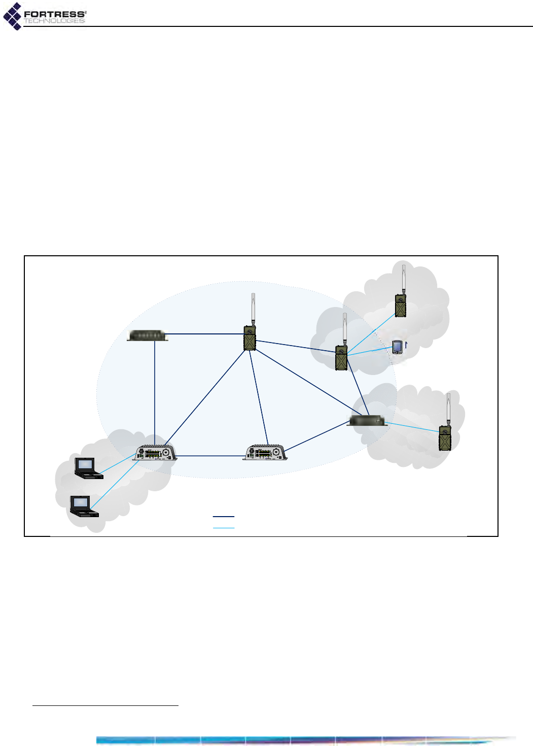
1.4.1.1 Isolated FastPath Mesh Networks
The independent RFC-4193 IPv6 mesh addressing and DNS
distribution functions embedded in FastPath Mesh enable a set
of Fortress Bridges to form a fully functioning FastPath Mesh
network as soon as they are connected.
Figure 1.1. Isolated FP Mesh Network with Access Network Connections
In the case of an isolated wireless FP Mesh network, as shown
in Figure 1.1, on each Bridge to be used as an MP you must, at
minimum:
License FastPath Mesh on the Bridge:
on Maintain -> Licensing
Select FastPath Mesh for Bridging Mode:
on Configure -> Administration
Enable the internal radio(s):
on Configure -> Radio Settings
2. Internet Engineering Task Force Request for Comments
NMP
NMP
Access
Network
Access
Network
Access
Network
NMP = Non-Mesh Point
= Mesh Core Connection
= Access Network Connection
MP = Mesh Point
NMP
ES210 in
STAtion mode
NMP
ES210 in
STAtion mode
NMP
MP
ES820
MP
ES520
MP
ES210
MP
ES520
MP
ES210
MP
ES820

Bridge GUI Guide: Introduction
7
Create a bridging BSS on (one of) the radio(s) with:
NOTE: A BSSs
bridging setting
also determines its FP
Mesh function. With
Wireless Bridge Enabled,
BSSs function as Core
interfaces; with Wireless
Bridge Disabled they
function as Access inter-
faces (Section 3.3.4.3).
an SSID in common with the bridging BSSs on the rest
of the MPs
a Wireless Bridge setting of Enabled
on Configure -> Radio Settings -> ADD BSS
If the current MP will connect NMPs to the network, create
an Access BSS on (one of) the radio(s) with:
an SSID for NMP devices to connect to
a Wireless Bridge setting of Disabled
on Configure -> Radio Settings -> ADD BSS
The Bridge will force you to change the password of the
preconfigured administrator account when you log in for the
first time. The Bridge is not fully secure until you have also
changed passwords for the two remaining preconfigured
administrative accounts and the network Access ID from their
defaults.
Including the RFC-4193 IPv6 address FP Mesh automatically
generates, each MP can have up to sixteen IPv6 addresses. It
always has a link-local address and can always have a
manually configured IPv6 global address. If IPv6 Auto
Addressing is Enabled (the default) and an IPv6 router is
present on the network to provide routing prefixes, additional
IPv6 addresses will be present. Each MP can also have a
manually configured IPv4 address. Refer to Section 3.4.2 for
more on IP addressing on the Bridge.
To provide virtually configuration-free DHCP and DNS services
for Non-Mesh Points on the FP Mesh network, enable one (or a
few) of the DHCP servers internal to the network MPs and
leave all of their internal DNS servers enabled (the default).
The Bridge’s DNS service is used in common by IPv4 and IPv6
networks, while the Bridge provides separate, dedicated IPv4
and IPv6 DHCP servers. Refer to Section 3.6 for more on the
Bridge’s internal DHCP and DNS servers.
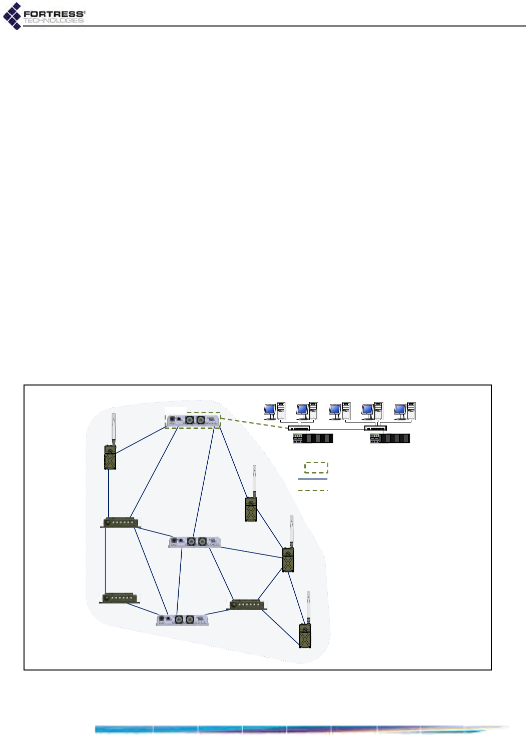
1.4.1.2 Network-Attached FastPath Mesh Networks
One or more of the Mesh Points in a FastPath Mesh network
can connect the mesh to a conventional hierarchical LAN or
WAN (wide are network). An MP that serves as a bridge
between the FP Mesh network and a hierarchical network is a
Mesh Border Gateway (MBG).
The MBG interface that connects to the LAN or WAN must be
configured as an Access interface, the MBG’s default gateway
must be a router on the hierarchical network, and route(s) to
the FastPath Mesh's subnet must be configured on the network
router(s). If IPv6 network routers are configured to provide an
IPv6 global prefix, the MBG will forward it to every node in the
network (MPs and NMPs).
Bridge GUI Guide: Introduction
8
If a DHCP server internal to one of the MPs is enabled to
configure the IP addresses of network NMPs, all NMPs will
have the correct default gateway address and IPv6 prefix to
automatically configure themselves without further manual
configuration.
To create a FastPath Mesh network and attach it to a
conventional hierarchical network, as shown in Figure 1.2, you
must, at minimum:
follow the steps to configure an isolated FastPath Mesh
network outlined in the preceding Section 1.4.1.1.
on each Mesh Point that will serve as an MBG:
configure the hierarchical network router as the MBG’s
default gateway: on Configure -> Administration ->
Network Configuration.
be sure the interface that will connect to the hierarchical
network is configured as an FP Mesh Access interface.
FastPath Mesh Mode is specified for wired interfaces: on
Configure -> Ethernet Settings -> EDIT. Wireless
interfaces are automatically (and transparently)
configured as Access interfaces when Wireless Bridge
is Disabled: on Configure -> Radio Settings -> ADD BSS.
on each router in the hierarchical network that will connect
to an MBG, configure route(s) to the FP Mesh subnet.
Figure 1.2. Single FP Mesh Network with a Single MBG Attachment Point
03
03
03
03
03
03
/$1
MBG
03
03 0HVK3RLQW
MBG 0HVK%RUGHU*DWHZD\
0HVK&RUH&RQQHFWLRQ
0HVKļ+LHUDUFKLFDO&RQQHFWLRQ
$FFHVV,QWHUIDFH
ES820
ES820
ES440
ES440
ES440
ES210
ES210
ES210
03
ES820
03
ES210
Bridge GUI Guide: Introduction
9
In addition to the RFC-4193 IPv6 address FP Mesh
automatically generates, the MBG is provided with a global
prefix by the network IPv6 router. If a DHCP server internal to
one of the MPs is enabled, each IPv6 node in the network can
then be reached by the public address so provided.
NOTE: There is no
coordination be-
tween FP Mesh MBGs.
You can attach an FP Mesh network to a hierarchical network
by more than one MBG to provide path redundancy between
the mesh and the LAN or WAN. If one of the MBGs becomes
unavailable, the other(s) will maintain the connection.
Regardless of the number of MBGs attached to the hierarchical
network, traffic into the FP Mesh network typically flows
through only one MBG. If two (or more) MBGs are used, you
can manually split traffic between the two MBGs by IPv4
address ranges (10.1/16->MBG1, 10.2/16->MBG2, for
example), but it will still be the case that only one MBG will
send traffic to any given FP Mesh node.
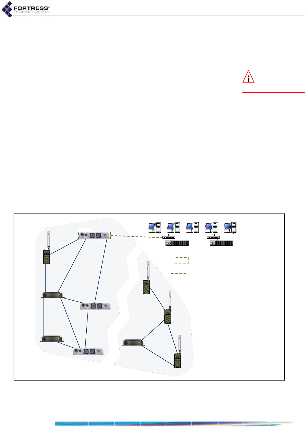
1.4.1.3 Separating and Rejoining in FastPath Mesh Networks
Mesh Points in a wireless FastPath Mesh network can
separate and rejoin smoothly, individually or in groups, as
mobile Mesh Points move in and out of range of each other.
Changes in the costs and availability of FP Mesh data paths
are propagated throughout the network.
Figure 1.3. Single Separated FP Mesh Network
When a split forms in a mobile FP Mesh network attached to a
hierarchical network, as shown in Figure 1.3, any nodes
03
03
03
03
03
03
/$1
MBG
03
03 0HVK3RLQW
MBG 0HVK%RUGHU*DWHZD\
0HVK&RUH&RQQHFWLRQ
0HVKļ+LHUDUFKLFDO&RQQHFWLRQ
$FFHVV,QWHUIDFH
03
03
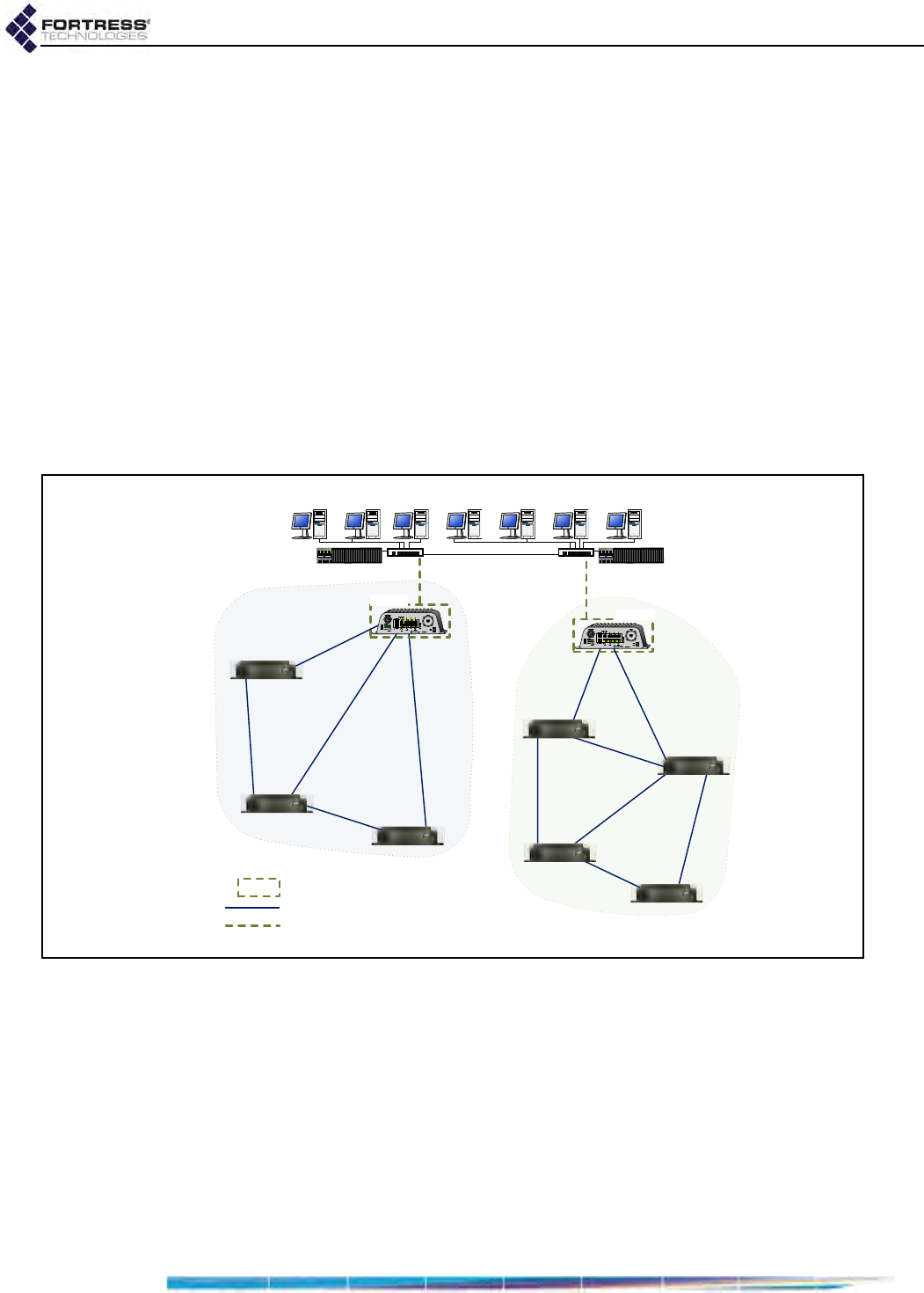
Bridge GUI Guide: Introduction
10
separated from the MBG will be temporarily disconnected from
the hierarchical network. Multiple MBGs can enable parts of the
mesh temporarily separated from each other to remain
connected to a hierarchical network, as long as there is an
MBG present among the separated group of nodes.
1.4.1.4 Bridging Loops in FastPath Mesh Networks
Bridging loops can form only when FastPath Mesh Points are
connected over both Core and Access interfaces.
In FastPath Mesh Networks with single MBG attachment points
to the hierarchical network, such as those shown in Figure 1.4,
simultaneous Core and Access connections are not present,
and bridging loops cannot form. Although the two MBGs are
connected to the same LAN by their Access interfaces, they
are MPs in different FP Mesh networks and so are not also
connected by Core interfaces.
Figure 1.4. Two FP Mesh Networks, One MBG Attachment Point Each, Connected to a Single Access Network
When a FastPath Mesh network is attached to a hierarchical
network by two (or more) Mesh Border Gateways, the Mesh
Points serving these roles are connected to each other both by
their Core interfaces and by the Access interfaces connecting
them to the hierarchical network. FastPath Mesh detects and
prevents the loop that would otherwise form over these
connections:
Among the many MPs that detect a loop, only the MP with
the lowest MAC address will forward mesh traffic received
03
03
03
/$1
Mesh A
Mesh B
MBG MBG
03 0HVK3RLQW
MBG 0HVK%RUGHU*DWHZD\
0HVK&RUH&RQQHFWLRQ
0HVKļ+LHUDUFKLFDO&RQQHFWLRQ$FFHVV,QWHUIDFH
03
03
03
03
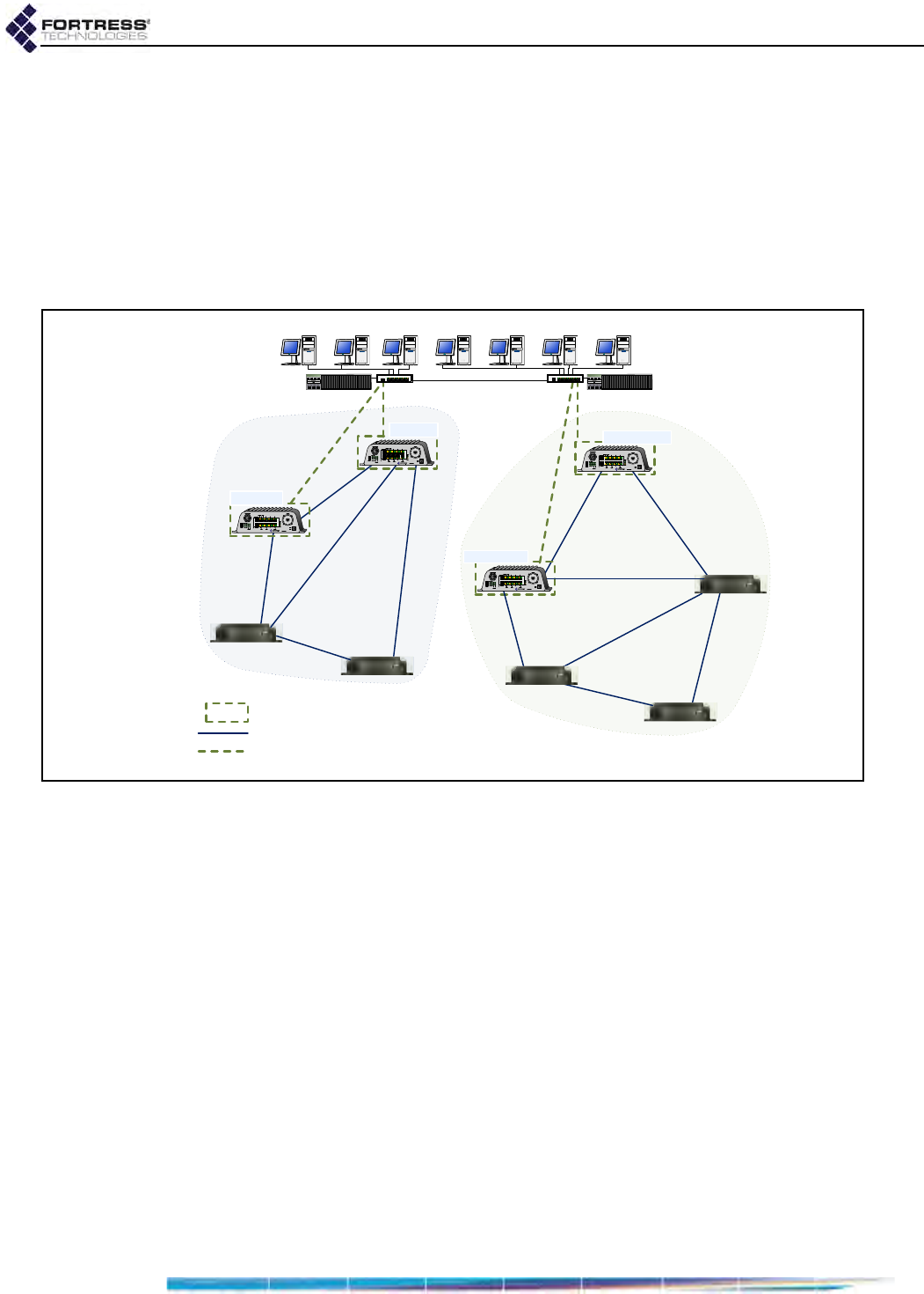
Bridge GUI Guide: Introduction
11
on the Access interfaces on which the loop has been
detected.
Only the MP so chosen as the forwarder will advertise
NMPs discovered on these Access interfaces.
Because only one MBG in a given FP Mesh network will
actively pass traffic to and from the hierarchical network,
multiple MBGs can be present in multiple FP Mesh networks
attached to the same LAN, as shown in Figure 1.5.
Figure 1.5. Two FP Mesh Networks, Two MBGs Each, Connected to a Single Access Network
1.4.1.5 Traffic Duplication in FastPath Mesh Networks
Although you can attach more than one FP Mesh network
simultaneously to more than one LAN, configurations in which
separate hierarchical networks are “bridged” by multiple FP
Mesh networks will necessarily generate duplicate traffic, as
shown in Figure 1.6.
/$1
Mesh A
Mesh B
MBG A2
MBG A1
MBG B1
MBG B2
03 0HVK3RLQW
MBG 0HVK%RUGHU*DWHZD\
0HVK&RUH&RQQHFWLRQ
0HVKļ+LHUDUFKLFDO&RQQHFWLRQ$FFHVV,QWHUIDFH
03
03
03
03
03
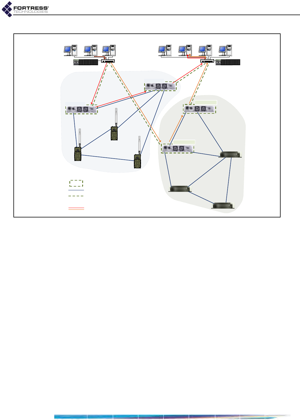
Bridge GUI Guide: Introduction
12
Figure 1.6. Traffic Duplication in Two FP Mesh Networks Attached to Separate Access Networks
Avoid such configurations if traffic duplication is undesirable in
your environment.
1.4.2 STP Mesh Network Deployments
Fortress Bridges can be deployed in mesh networks managed
by Spanning Tree Protocol without any additional features
licensing.
When STP is selected for Bridging Mode (the default), the
Bridge can be used as a node in an STP-managed mesh
network while—on a separate BSS—also acting as an AP
(access point) to WLAN client devices within range.
LAN 2
03 0HVK3RLQW
MBG 0HVK%RUGHU*DWHZD\
0HVK&RUH&RQQHFWLRQ
0HVKļ+LHUDUFKLFDO&RQQHFWLRQ
$FFHVV,QWHUIDFH
Mesh A
Mesh B
LAN 1
VHQGHU WDUJHW
'XSOLFDWH7UDIILF
MBG B2
MBG A1
MBG A2
MBG B1
03
03
03
03
03
03
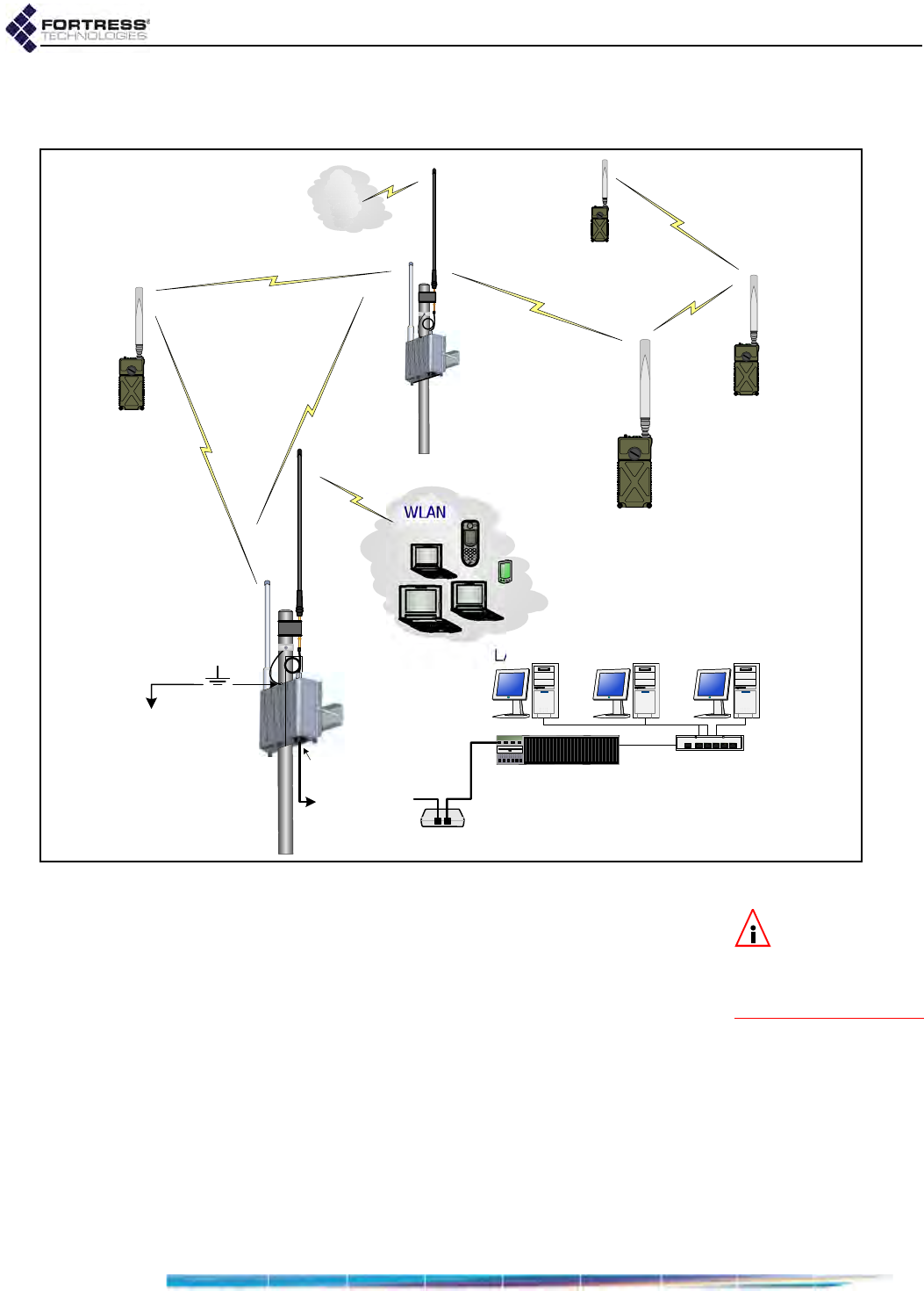
Bridge GUI Guide: Introduction
13
Bridges configured to be able to connect to one another
automatically form mesh networks.
Figure 1.7. STP Mesh Network Deployment
NOTE: Refer to
Section 3.2.2 for
more on STP bridging
and configuring Bridge
Priority.
At their default settings, the Bridge with the lowest MAC
address will serve as the STP root. Alternatively, you can
configure the order in which networked Bridges will assume the
role of STP root, if the existing root is lost, by specifying the
Bridge Priority order on individual Bridges in an STP network.
One or more of the linked Bridges (or network nodes) can also
be configured to connect the mesh network to a LAN and/or to
serve as a WLAN AP for compatibly configured wireless clients
within range. Figure 1.7 shows an STP mesh network in which
all connected nodes are serving as WLAN APs and the STP
root node is attached to a LAN.
LAN
WLAN
...rear-panel
grounding stud
to earth
ground
WAN
port
mast-
mounted
ES520
STP Root
WLAN
...to PoE power
PoE adapter
(implementation dependent on lightning arrestor)
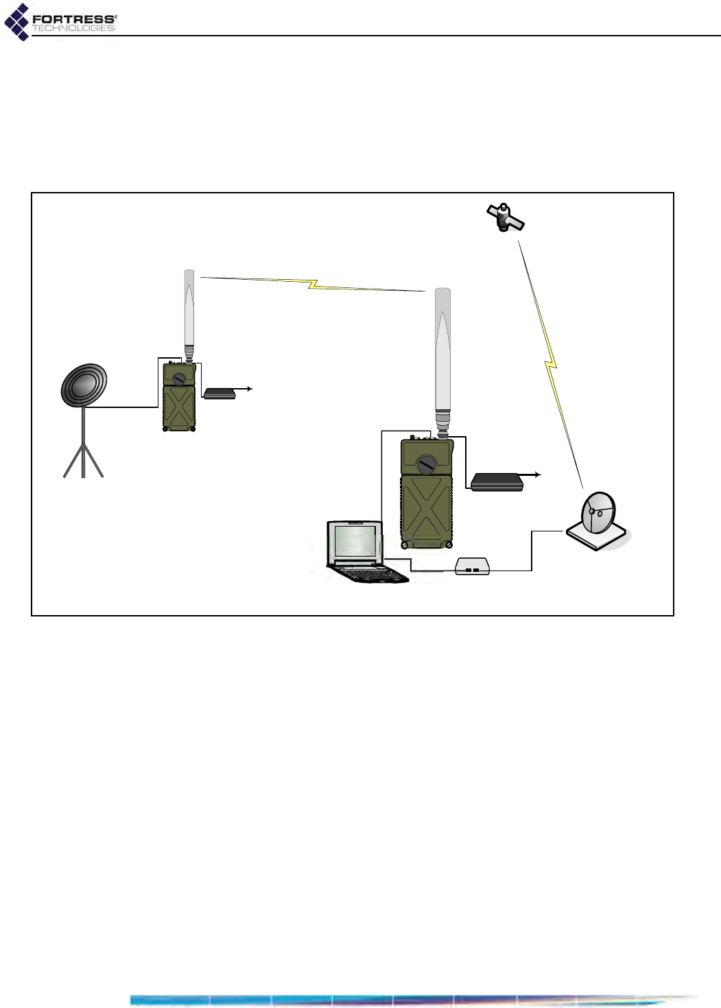
Bridge GUI Guide: Introduction
14
1.4.3 Point-to-Point Bridging Deployments
The Bridge can be deployed as a conventional wireless Bridge
to connect two separately located LANs (local area networks),
for example, or to link remotely located hardware to the local
network for system management and data upload, as shown in
Figure 1.8).
Figure 1.8. Point-to-Point Wireless Bridging Deployment
As long as the LAN or WAN to which the Bridge is connecting
does not require STP to be enabled, Bridges can be deployed
in point-to-point (two-node) bridging configurations without any
link management (with a Bridging Mode setting of Off).
If more than two Bridges will be networked, Fortress strongly
recommends using FastPath Mesh (if licensed) or STP link
management.
1.4.4 Wireless Client ES210 Bridge Deployments
An ES210 Bridge can be dedicated to operate as a standard
802.11 wireless client by configuring a single station (STA)
interface on its single internal radio.
ES210 Bridges operating as wireless client devices can be
integrated into Bridge-secured network deployments as any
WLAN client would be: connecting to the WLAN (or access
network) through another Bridge acting as a network AP (or
configured with an access interface).
remote hardware
modem
satellite uplink
management laptop
wireless bridging link
...to power
Ethernet
Ethernet

Bridge GUI Guide: Introduction
15
1.5 Compatibility
The Fortress Bridge is fully compatible with WPA and WPA2
enterprise and pre-shared key modes and with Fortress Secure
Client versions 2.5.6 and later.
In addition or as an alternative to the Bridge’s native
authentication service, the Bridge can be used with an external
RADIUS server. Supported services include:
Microsoft® Windows Server 2003 Internet Authentication
Service® (IAS)
freeRADIUS version 2.1 (open source)

Bridge GUI Guide: Administrative Access
16
Chapter 2
Bridge GUI and Administrative Access
2.1 Bridge GUI
The Fortress Secure Wireless Bridge’s graphical user interface
provides access to Bridge administrative and monitoring
functions.
2.1.1 System Requirements
To display properly, the Bridge GUI requires a monitor
resolution of at least 1024 × 768 pixels and the following (or
later) browser versions:
Microsoft® Internet Explorer 7.0
Mozilla Firefox™ 2.0
2.1.2 Bridge GUI Security
Browser connections to the Bridge’s management interface are
secured via https (Hypertext Transfer Protocol Secure). GUI
access can be authenticated via the self-signed X.509 digital
certificate automatically generated by the Bridge for use by
SSL (Secure Socket Layer) and present by default in the local
certificate store. You can also import and select a different
certificate for the Bridge's SSL function (refer to Section 6.2).
You can turn off GUI access to the Bridge altogether by
disabling the user interface, requiring administrators to access
the Bridge exclusively through the CLI (refer to Section 4.1.5).
The Bridge GUI is enabled by default.
NOTE: The default
IP address is
192.168.254.254. Default
passwords for precon-
figured accounts are the
accounts’ respective
user names (refer to Sec-
tion 2.2.2) and must be
changed when the ac-
count is first used.
2.1.3 Logging On
You can access the Bridge GUI from any computer with access
to the Bridge: any computer on one of the Bridge’s clear
interfaces, as well as any computer with a secure connection to
an encrypted interface.
To access the Bridge GUI:
1Open a browser and, in the address field, enter the IP
address assigned to the Bridge’s management interface.
2If this is the first time an administrator has logged on to the
Bridge and you agree to the terms of the license
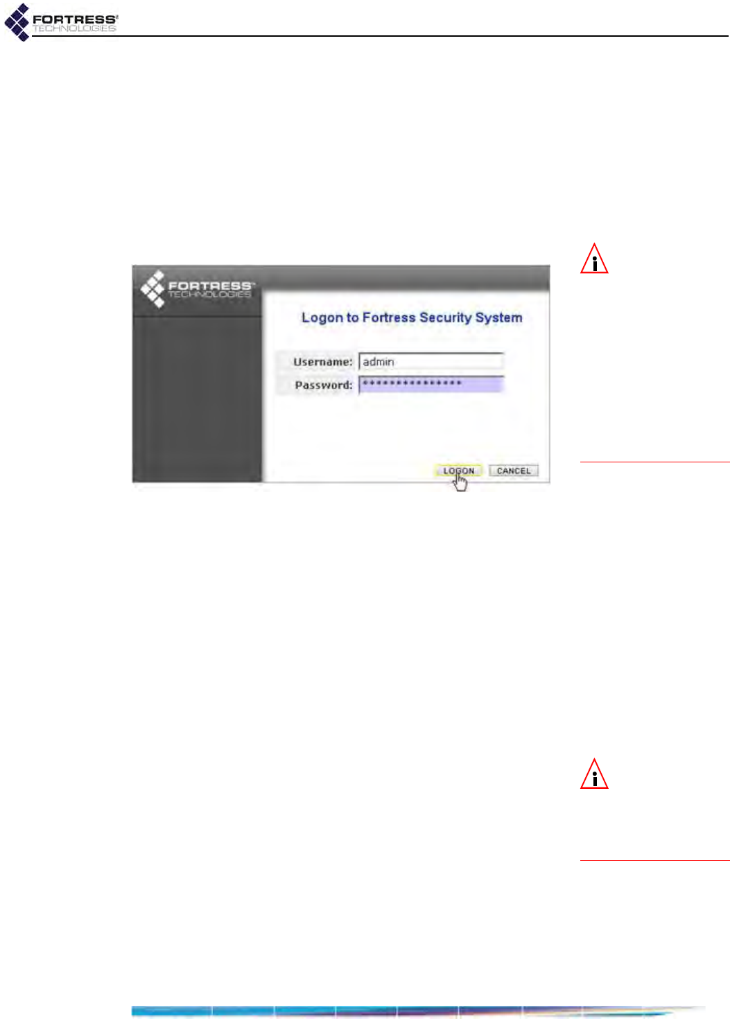
Bridge GUI Guide: Administrative Access
17
agreement, click to accept them. (Once accepted the
agreement does not display.)
or
If an administrative logon banner has been configured
(Section 2.2.1.9)—click to accept its terms. (There is no
administrator logon banner by default.)
3On the Logon to Fortress Security System screen, enter a
valid Username and Password.
NOTE: Default
complexity re-
quirements force pass-
words to be changed on
all three preconfigured
accounts when the ac-
counts are first used. If
password requirements
are changed to permit
the defaults, first-time
logons to Maintenance
and Logviewer will not
force password changes.
4Click LOGON.
Figure 2.1. Bridge GUI
Logon
screen, all platforms
5If prompted to do so, enter and confirm a new password for
the account and click SUBMIT.
You will be prompted to create a new password if:
You are logging on to the Bridge for the first time.
The account password has expired or has been expired
for non-conformance (refer to Section 2.2.1.7).
The User must change password: Yes option is in effect
for the account you are trying to log on (Section 2.2.2).
You can optionally view current password complexity
requirements by clicking Complexity Requirements at the
bottom of the Create a new password dialog.
NOTE: You can
view but not edit
the list against which
passwords are checked
by clicking Password Dic-
tionary: VIEW.
If Pass. Dictionary is enabled (refer to Section 2.2.1.8), new
passwords are checked against the list of words used by
the function. You can pre-check the password against the
list by clicking Pass. Dictionary: CHECK PASSWORD. The
message Not Blacklisted will be returned if the entry passes
the check; Blacklisted! indicates that the entry failed the
check and cannot be used. By default, the password
dictionary check is not in effect, and it is labeled disabled.
6If you were prompted to create a new password, the Logon
to Fortress Security System screen displays again: re-enter
the account Username, enter the new Password, and click
LOGON.
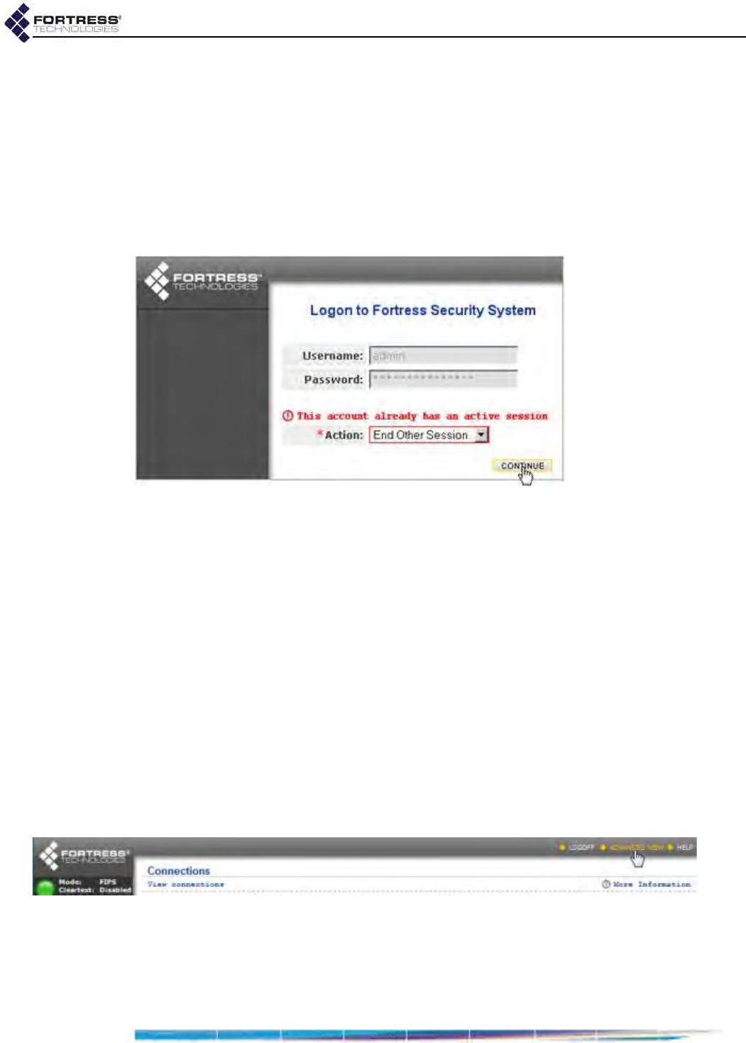
Bridge GUI Guide: Administrative Access
18
Two administrators with Administrator-level privileges (refer to
Section 2.2.2.3) cannot be logged on the Bridge at the same
time.
If you are trying to log on to an Administrator-level account
when another such session is active, you will have the option of
forcibly ending the active session and proceeding with the
logon, or choosing Cancel Logon from the dropdown to
preserve the first session. Click CONTINUE to execute your
choice.
Figure 2.2. Bridge GUI
Logon
screen when the account is active, all platforms
Access configuration settings through the menu links under
Configure on the left of all Bridge GUI screens. Monitoring
functions are available under Monitor, maintenance and
diagnostic tools under Maintain.
2.1.4 Using Bridge GUI Views
The Bridge GUI initially opens in Simple View, which displays
an abbreviated set of items under the main menu headings on
the left side of the page and provides a limited set of
configuration settings on Configure screens.
To access the complete Bridge GUI, click ADVANCED VIEW in the
upper right corner of any page. The Bridge GUI Advanced View
includes additional items under the Configure and Maintain main
menu headings and provides full access to configuration
settings. In Advanced View, the button in the upper right corner
changes to SIMPLE VIEW.
Figure 2.3. Bridge GUI
VIEW
buttons, all platforms
For Administrator-level accounts, Advanced View-selection is
persistent over subsequent log-ons and reboots. The Advanced
View button is absent altogether when you are logged into a
Log Viewer-level account, where it would serve no purpose

Bridge GUI Guide: Administrative Access
19
(refer to Section 2.2.2.3 for more information on account roles
and access).
On a screen common to both views, you can toggle between
the two views of the screen. If you are viewing a screen
exclusive to the Advanced View and you click SIMPLE VIEW, the
Bridge GUI will return the main page for the function or, if no
such page exists in Simple View, the Monitor -> Connections
screen.
2.1.5 Accessing Bridge GUI Help
Access the table of contents for Bridge GUI help by clicking
HELP in the upper right corner of every page. For help with the
screen you are currently viewing, click More Information in the
upper right of the screen.
2.1.6 Logging Off
To log off the Bridge GUI, click LOGOFF, in the upper right
corner of the screen.
If you simply close the browser you have used to access the
Bridge GUI, you will not be logged off completely. Although you
must re-open you browser and log back on to the Bridge in
order to regain access to the same account, the previous
administrative session persists until it times out or, at the point
of logging back in to the account, you opt to end it.
By default, the Bridge is configured to end administrative
sessions after 10 minutes of inactivity, automatically logging
the administrator off. You can reconfigure the global
administrative Session Idle Timeout (refer to Section 2.2.1.4).
2.2 Administrative Accounts and Access
NOTE: The precon-
figured admin, Ad-
ministrator-level, account
corresponds to the
Crypto Officer role as
defined by Federal In-
formation Processing
Standards (FIPS) 140-2.
There are three levels of permissions for administrative
accounts on the Bridge, determined by Role assignment:
Administrator account users have unrestricted access to
management functions and system information on the
Bridge.
Maintenance account users can view complete system and
configuration information and perform a few administrative
functions but cannot make configuration changes beyond
changing their own passwords (Section 2.2.2.11), if
permitted (the default).
Log Viewer account users can view only high-level system
health indicators and only those log messages unrelated to
configuration changes. If permitted (the default), they can
also change the password for the account.
For more detail on account privileges refer to Section 2.2.2.3.
By default, one of each administrative account type is present
in the Bridge’s local administrator database, with the
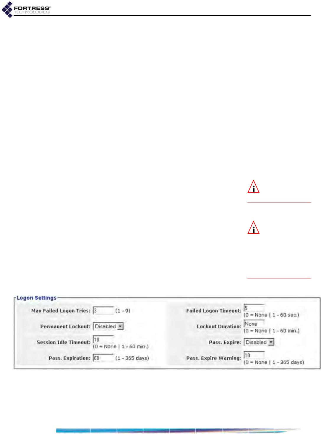
Bridge GUI Guide: Administrative Access
20
predetermined user names: admin, maintenance, and logviewer,
respectively. Administrative roles are described in greater detail
in Section 2.2.2.3.
Default passwords for preconfigured accounts are the same as
their user names.
The first time you log on to the admin account, you will be
forced to enter a new password of at least 15 characters.
Administrative password requirements are global and
configurable: refer to Section 2.2.1.8. The default complexity
requirements will force the passwords to be changed on all
three preconfigured accounts when the accounts are first used.
If password requirements are changed so that the default
passwords are acceptable, however, administrators logging on
to the Maintenance and Logviewer accounts for the first time,
will not be forced to change these account passwords from
their defaults. All default passwords should nonetheless be
changed in order to fully secure the Bridge’s management
interface.
NOTE: Preconfig-
ured accounts can-
not be deleted.
An administrator logged on to an Administrator-level account
can specify a number of global administrative account settings.
In Advanced View, you can also add up to ten additional
administrative accounts, as well as reconfigure individual
account settings and delete accounts.
NOTE:
Except for
Session Idle Time-
out
changes, which take
effect immediately,
changes to global
Logon
Settings
are applied at
the next administrator
logon.
Global administrative account settings are covered in Section
2.2.1 (below). Individual administrative account management is
covered in Section 2.2.2.
2.2.1 Global Administrator Settings
A number of configurable parameters apply globally to
administrative accounts’ logon behaviors and passwords and
to administrator authentication. View the these settings through
Configuration -> Security -> Logon Settings.
Figure 2.4. Simple View
Logon Settings
frame, all platforms
2.2.1.1 Maximum Failed Logon Attempts
You can configure how many times an administrator can try
unsuccessfully to log on to one of the Bridge’s administrative
accounts before the account is subject to the Bridge’s currently

Bridge GUI Guide: Administrative Access
21
configured lockout behavior. Numbers from 1 to 9 are
accepted; 3 is the default.
NOTE:
The lock-
out feature applies
only to remote logon at-
tempts. The
Bridge
CLI
unlock
command can
always be executed via a
physical connection to
the
Console
port, which
is never locked. Refer to
the
CLI Software Guide
.
2.2.1.2 Failed Logon Timeout
The Failed Logon Timeout setting specifies the number of
seconds that must elapse after a failed logon attempt before
the same administrator can successfully log on with valid
credentials.
If an administrator enters valid credentials before the specified
number of seconds have elapsed, the action is interpreted as
another failed logon attempt and the timeout counter resets.
You can set Failed Logon Timeout from 0 (zero) to 60 seconds;
a setting of 0 disables the function (no delay between logon
attempts will be enforced). The default Failed Logon Timeout is
5 seconds.
2.2.1.3 Lockout Behavior
You can set the length of time an administrator will remain
locked out after reaching the specified maximum logon
attempts in Lockout Duration.
Alternatively, by enabling Permanent Lockout you can configure
the Bridge to keep the account locked until you have logged on
to the Bridge GUI through an Administrator-level account and
unlocked it.
If there is no other Administrator-level account available, you
can unlock the account only through a direct, physical
connection to the Bridge’s Console port, with the Bridge CLI’s
unlock command. Administrative access to the Console port is
never locked. Refer to the CLI Software Guide.
Administrator accounts are locked when you exceed the
maximum permitted number of failed logon attempts (Section
2.2.1.1) on the account. Attempts to log on fail when you
supply invalid credentials and when you neglect to allow the
specified period between failed attempts (Section 2.2.1.2).
NOTE: The idle
timeout setting for
local administrator ac-
counts is independent
of timeout settings for
network users and con-
necting devices (Section
4.4).
Refer to Section 2.2.2.12 for instructions on unlocking an
administrative account in the Bridge GUI.
2.2.1.4 Session Idle Timeout
By default, administrative sessions time out after 10 minutes of
inactivity. You can disable administrative session timeouts with
a Session Idle Timeout setting of 0 (zero) or reconfigure the
timeout period in whole minutes between 1 and 60.
2.2.1.5 Show Previous Logon
When Show Previous Logon is Enabled, the date and time the
current administrator last logged on and the IP address and
user interface (GUI or CLI) used to do so are displayed at the
top of the first page displayed by the Bridge GUI (Monitor ->
Connections for initial Administrator- or Maintenance-level

Bridge GUI Guide: Administrative Access
22
log-ons and Monitor -> Event Log when Log Viewer accounts
first access the Bridge GUI). The feature is Disabled by default.
Show Previous Logon is present only in Advanced View (refer to
Section 2.1.4).
2.2.1.6 Authentication Method and Failback
NOTE: Adminis-
trators added in
the external authentica-
tion service are Learned
by the Bridge, but can-
not be authenticated un-
til their records have
been opened locally for
configuration (refer to
Section 2.2.2.8).
By default, administrative Usernames and passwords are
authenticated by the Local administrator authentication
service—a designated service running on the Bridge itself and
separate from the local user authentication service configured
on Configure -> RADIUS Settings -> Local Server (refer to
Section 4.3.2).
Alternatively, you can reconfigure the Bridge to send
administrators’ logon credentials to a Remote Authentication
Dial-In User Service (RADIUS) server, which may be any of:
the RADIUS server internal to the current Bridge
the RADIUS server internal to another Bridge on the
network
a third-party RADIUS server running on the network
The service(s) available are determined by the Bridge’s
configuration for authentication servers as determined by the
settings on Configure -> RADIUS Settings.
When a Fortress or a third-party RADIUS server is used to
evaluate administrator logon credentials, locally configured
logon settings and password rules do not apply. Administrative
logon behavior and password rules are determined by the
account settings in effect on that RADIUS server.
When the Bridge is configured to use a third-party or Fortress
RADIUS server and Authentication Failback is Enabled, the
Bridge will use its local administrator authentication service as
a backup means of authenticating administrator credentials,
should the third-party or Fortress user authentication database
become unavailable.
When Authentication Failback is disabled (the default) on a
Bridge configured to use a third-party or Fortress RADIUS
server for administrator authentication, and no such server is
available, administrators cannot be authenticated and logged
on to the Bridge until access to the external server is restored.
Authentication Failback is not applicable to Bridges configured
with the default Authentication Method of Local.
Authentication Method and Authentication Failback are present
only in Advanced View (refer to Section 2.1.4).
To use the local Fortress RADIUS Server
to authenticate administrators:
Except for steps 7 through 11, which can be performed at any
time, you must follow the steps of the procedure below in the
order given.
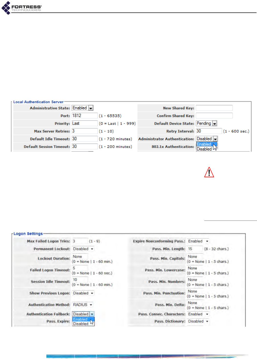
Bridge GUI Guide: Administrative Access
23
1Log on to the Bridge GUI through an Administrator-level
account and select ADVANCED VIEW in the upper right corner
of the page, then Configure -> RADIUS Settings from the
menu on the left.
2Click to access the Local Server tab, and in the Local
Authentication Server frame:
In Administrative State, click to select Enabled.
In Administrator Auth, click to select Enabled.
For help with other settings on this screen refer to Section
4.3.2.
Figure 2.5. enabling local administrator authentication, all platforms
CAUTION: For-
tress strongly rec-
ommends selecting
Enabled for Auth Fail-
back to insure against
administrative lockout
in the event of network
disruptions or adminis-
trator error.
3Click APPLY in the upper right of the screen.
4Select Configure -> Security from the menu on the left.
5In the Security screen’s Logon Settings frame:
In Authentication Method, select RADIUS from the
dropdown.
In Auth Failback, optionally click to select Enabled.
For help with other settings in this frame refer to the rest of
this section.
Figure 2.6. enabling administrator authentication failback, all platforms
6Click APPLY in the upper right of the screen.
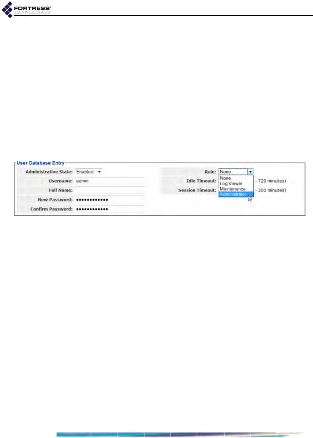
Bridge GUI Guide: Administrative Access
24
7Select Configure -> RADIUS Settings from the menu on the
left.
8Click to access the Local Server tab and in the User Entries
frame, click NEW USER.
9In the Edit Local Authentication screen’s User Database
Entry frame:
In Username, enter a user name of at least one (1)
alphanumeric characters.
In New Password/Confirm Password, enter a password
that confirms to current password requirements
(Section 2.2.1.8).
In Role, select Administrator from the dropdown.
For help with other settings in this frame refer to Section
4.3.3.1.
Figure 2.7. creating an administrator account on the local authentication server, all platforms
10 Click APPLY in the upper right of the screen.
11 Repeat steps 8 through 2.7 for any additional
administrators you want to configure.
To use a remote Fortress
RADIUS
Server
to authenticate administrators:
To use a RADIUS server running on another Bridge on the
network to authenticate administrators for the local Bridge, you
must configure an entry for the server on the local Bridge’s
Authentication Servers page, specifying Fortress Auth as its
Server Type and Admin as a supported Auth Type (refer to
Section 4.3.1).
Only administrators with user accounts (configured for the Role
of Administrator) on the remote Bridge will be able to
authenticate through its user authentication service (refer to
Section 4.3.3.1).
To use a third-party RADIUS Server
to authenticate administrators:
To use a third-party RADIUS server for administrator
authentication, it must be configured to use Fortress’s Vendor-
Specific Attributes for Fortress-Administrative-Role and Fortress-
Password-Expired, provided in the dictionary.fortress
configuration file included on the Bridge software CD and
available for download at www.fortresstech.com/support/.

Bridge GUI Guide: Administrative Access
25
Consult your RADIUS server documentation for information on
configuring the service. You must additionally configure an
entry for the server on the Bridge’s Authentication Servers list
(Configure -> RADIUS Settings-> Server List), specifying 3rd
Party RADIUS as its Server Type and Admin as a supported Auth
Type for the service (refer to Section 4.3.1 for more information
on configuring external authentication servers for the Bridge.).
2.2.1.7 Password Expiration
You can configure the Bridge to expire administrative
passwords after a specified period and to warn administrators a
specified number of days before the password expires.
Password expiration (Pass. Expire) is Disabled by default.
When Pass. Expire is Enabled, you can specify a password
expiration period (Pass. Expiration) of 1 to 365 days. The
default expiration period is 60 days.
Expiration Warning
You can also configure the Bridge to warn administrators that
their passwords are scheduled to expire. You can set Pass.
Expire Warning from 0 to 365. An expiration warning setting of 0
or a setting greater than the specified password expiration
period disables the function (no password expiration warning
will be issued). When a Pass. Expire Warning smaller than
Pass. Expiration is set, the warning **Your password will expire
soon** appears at the top of the first screen displayed (initially
Connections for Administrator-level accounts) whenever an
administrator logs on, beginning the specified number of days
before administrators are forced to change their passwords.
The warning does not persist after the administrator navigates
away from the first page viewed. (If Pass. Expiration and Pass.
Expire Warning are set to the same value, the warning will
display whenever an administrator logs on.)
Nonconformance Expiration
If you change the rules for administrative passwords (refer to
Section 2.2.1.8), some existing passwords may not conform to
the new requirements. Expire Nonconforming Pass. allows you
to choose whether such passwords will expire at the time the
rules change (Enabled) or will be allowed to persist until the
next scheduled expiration date (Disabled). By default, Expire
Nonconforming Pass. is Enabled: administrators are forced to
change nonconforming passwords the first time they log on
after the rules for passwords have changed.
Expire Nonconforming Pass. is present only in Advanced View
(refer to Section 2.1.4).

Bridge GUI Guide: Administrative Access
26
2.2.1.8 Password Requirements
NOTE: Passwords
do not need to be
unique.
The Bridge will not accept new passwords that do not meet
specified requirements. If you specify new requirements that
existing passwords do not meet, nonconforming passwords are
treated according to the Expire Nonconforming Passwords
setting (described in Section 2.2.1.7).
Configured complexity requirements apply equally to
administrative passwords and to those of locally authenticated
network users (Section 4.3.3.1).
You can apply up to nine rules for administrative and local user
passwords:
Pass. Minimum Length - Passwords must be at least the
specified number of characters long. You can specify
values from 8 to 32 characters. The default is 15.
Pass. Minimum Capitals - Passwords must contain at least
the specified number of uppercase letters. You can specify
values from 0 (zero) to 5; a 0 value (the default) allows
passwords containing no uppercase letters.
Pass. Minimum Lowercase - Passwords must contain at
least the specified number of lowercase letters. You can
specify values from 0 (zero) to 5; a 0 value (the default)
allows passwords containing no lowercase letters.
Pass. Minimum Numbers - Passwords must contain at least
the specified number of numerals. You can specify values
from 0 (zero) to 5; a 0 value (the default) allows passwords
containing no numerals.
Pass. Minimum Punctuation - Passwords must contain at
least the specified number of symbols from the set: ~ ! @
# $ % ^ & *( ) _ - + = { } [ ] | \ : ; < > , . ?
/ (excludes double and single quotation marks). You can
specify values from 0 (zero) to 5; a 0 value (the default)
allows passwords containing no symbols.
NOTE: Pass. Mini-
mum Delta and
Pass. History Depth are
tracked separately for
each administrative ac-
count.
Pass. Minimum Delta - Passwords must contain at least the
specified number of changed characters, as compared to
the previous password. You can specify values from 0
(zero) to 5. A 0 value disables the check: if Pass. History
Depth (below) is also Disabled (the default), the same
password can be used consecutively, without any change
(provided it still conforms to the rest of the rules in effect).
Pass. Minimum Delta is disabled by default.
Pass. Consecutive Characters - Passwords can/cannot
contain consecutive repeated characters or consecutive
characters in ascending or descending numeric or
alphabetic order. When Pass. Consecutive Characters is
Disabled, passwords cannot include the character pairs 98
or ab, for examples. When it is Enabled (the default),
passwords can contain consecutive characters in numeric
or alphabetic order.
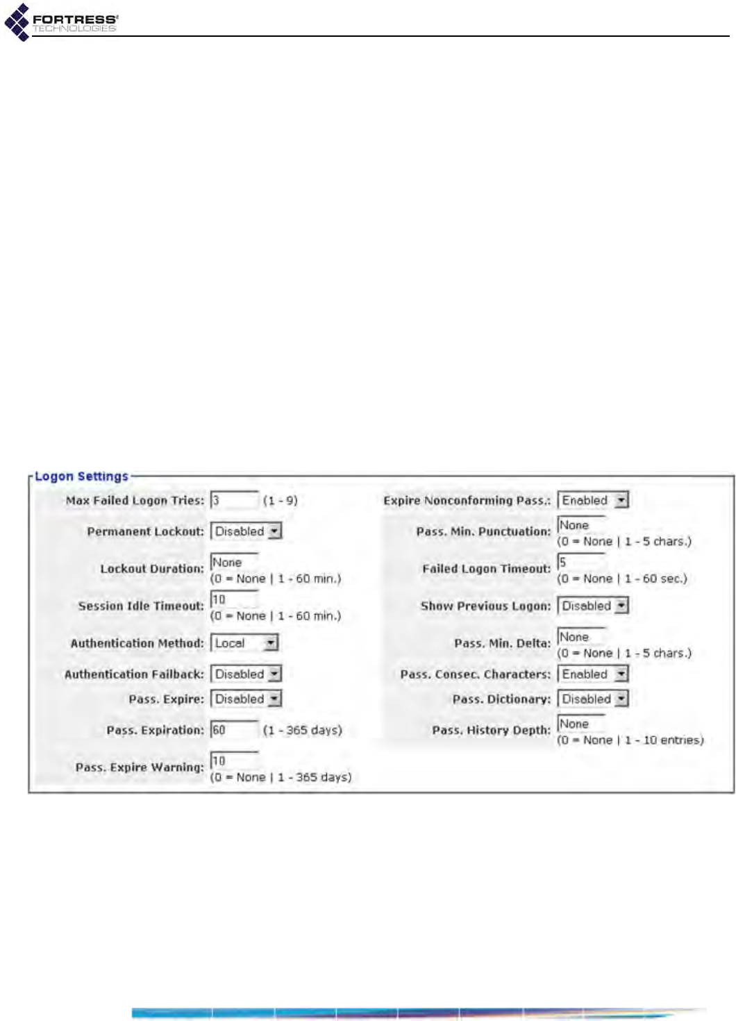
Bridge GUI Guide: Administrative Access
27
Pass. Dictionary - Passwords can/cannot match words in
the dictionary. When Pass. Dictionary is Enabled, passwords
are checked against a list of English words, and the
password is rejected if a match is found. When it is Disabled
(the default), passwords can contain the words on the list.
You can view but not edit the word list: Configuration ->
Admin Users -> EDIT|NEW USER -> Pass. Dictionary -> VIEW.
Pass. History Depth - Passwords cannot be reused until the
specified number of new passwords have been created.
You can specify values of 0 (zero) to 10. A 0 value disables
the check: if Pass. Minimum Delta (above) is also Disabled
(the default), the same password can be used
consecutively, without any change (provided it still
conforms to the rest of the rules in effect). Pass. History
Depth is disabled by default.
Password requirements settings are present only in Advanced
View (refer to Section 2.1.4).
To configure global administrative account settings:
The Bridge GUI’s Logon Settings are shown in Advanced View
below.
Figure 2.8. Advanced View
Logon Settings
frame, all platforms
Table 2.1 shows which Administrator Logon settings appear in
the two GUI views.

Bridge GUI Guide: Administrative Access
28
1Log on to the Bridge GUI through an Administrator-level
account and select Configure -> Security from the menu on
the left.
2If you are configuring one or more Advanced View settings
(see Table 2.1), click ADVANCED VIEW in the upper right
corner of the page. (If not, skip this step.)
3In the Security screen’s Logon Settings frame, enter new
values for those settings you want to configure (described
in sections 2.2.1.1 through 2.2.1.8).
4Click APPLY in the upper right of the screen (or RESET
screen settings to cancel your changes).
2.2.1.9 System Messages
The Comment field in the System Messages frame on Configure
-> Administration is intended as a user-configured informational
field. The Comment is displayed nowhere else.
You can configure a Warning Banner for display on the Bridge’s
administrator logon screens.
When a logon banner is present, administrators are prompted
to click to accept its conditions before they are permitted to
proceed with the logon.
There is no Warning Banner configured by default.
Table 2.1. Global Administrator Logon Settings
Simple & Advanced Views Advanced View Only
Max Failed Logon Tries Show Previous Logon
Failed Logon Timeout Authentication Method
Permanent Lockout Authentication Failback
Lockout Duration Expire Nonconforming Pass.
Session Idle Timeout Pass. Min. Length
Pass. Expire Pass. Min. Capitals
Pass. Expiration Pass. Min. Lowercase
Pass. Expire Warning Pass. Min. Numbers
Pass. Min. Punctuation
Pass. Min. Delta
Pass. Consec. Characters
Pass. Dictionary
Pass. History Depth
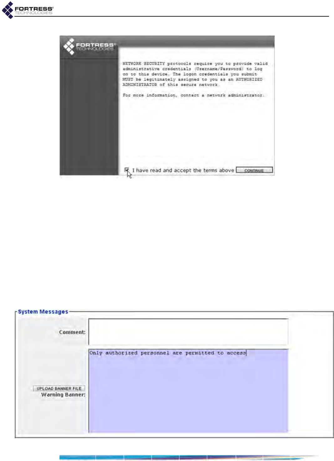
Bridge GUI Guide: Administrative Access
29
Figure 2.9.
Logon Banner
on the Bridge GUI
Logon Screen
screen, all platforms
To configure a comment or administrator logon banner:
1Log on to the Bridge GUI through an Administrator-level
account and select Configure -> Administration from the
menu on the left.
2Scroll down to the System Messages frame and:
Optionally enter information into the Comment field.
and/or
In the Warning Banner field enter or paste a message of
up to 2000 characters or click UPLOAD BANNER FILE to
upload text from an existing file.
3Click APPLY in the upper right of the screen (or RESET
screen settings to cancel your changes).
Figure 2.10.
System Messages
frame, all platforms
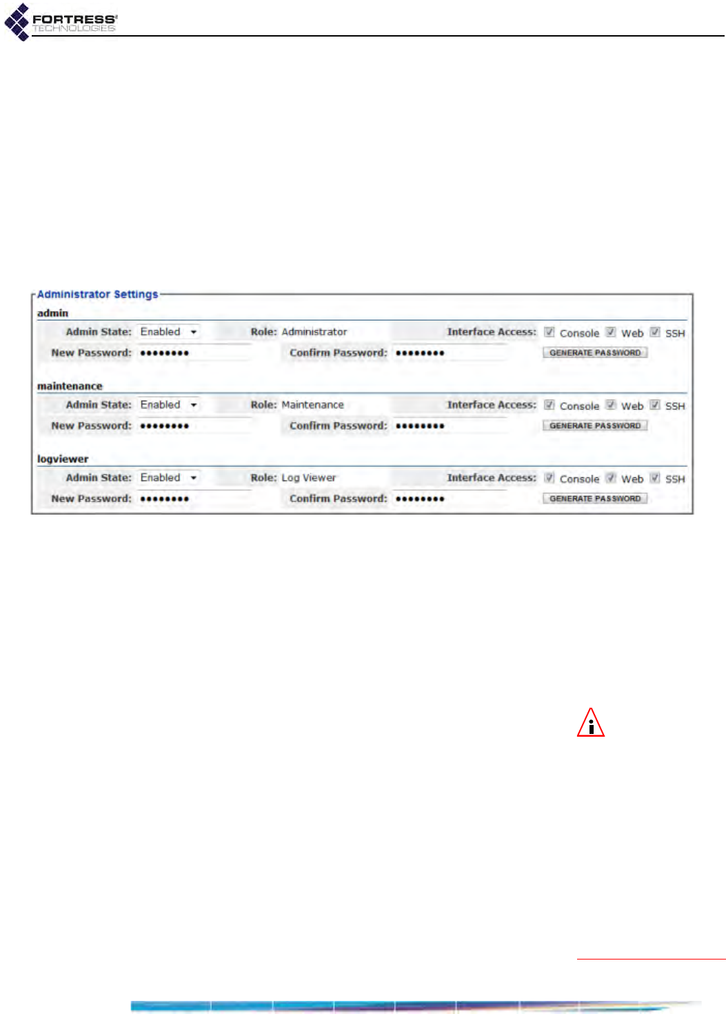
Bridge GUI Guide: Administrative Access
30
To eliminate an existing logon banner, delete all content from
the Warning Banner field and APPLY the change.
2.2.2 Individual Administrator Accounts
Up to thirteen usable administrative accounts can be present
on the Bridge’s local administrator database at one time.
Three of these are preconfigured with the fixed user names:
admin, maintenance and logviewer, reflecting the default
administrative Role of each account. While they can be
reconfigured (refer to Section 2.2.2.9), preconfigured
administrative accounts cannot be deleted.
Figure 2.11. Simple View
Administrator Settings
frame, all platforms
In Advanced View, you can add up to ten additional local
administrative accounts and configure additional account
parameters for both pre-configured and manually created
accounts.
On Bridges configured to authenticate administrators through a
third-party or Fortress RADIUS server (refer to Section 2.2.1.6),
an additional ten Learned administrative accounts can appear
on the Admin Users page.
NOTE: In order for
any account in the
local administrator da-
tabase to authenticate
an administrator, the
Bridge must be using
the local administrator
database for that pur-
pose (whether it has
been configured for Lo-
cal administrator au-
thentication or has
failed back to the local
administrator database
(Section 2.2.1.6).
Learned administrative accounts are not immediately usable to
locally authenticate administrators. In order to be usable for
local authentication, accounts for Learned administrators must
be converted to configured accounts on the local administrator
database (refer to Section 2.2.2.8). Learned accounts
converted to configured accounts are retained in the local
administrator database and count toward the maximum total of
thirteen configured accounts.
Although the credentials associated with a Learned account are
initially learned by the local administrator database from an
administrative account on another authentication service, the
two accounts are not linked in any way after the Learned
account has been converted to a configured account.

Bridge GUI Guide: Administrative Access
31
2.2.2.1 Administrator User Names
NOTE: In Ad-
vanced View, the
Username for any ac-
count listed in Adminis-
trator Settings links to a
Detailed Statistics dialog
for the account. Refer to
Section 5.2 for more in-
formation.
At the time a new administrative account is created, you must
provide a Username. Once established, the Username
associated with an administrative account cannot be changed.
Administrator user names must be unique on the Bridge. They
are case sensitive, can be from 1 to 32 characters long, and
can include spaces and any of the symbols in the set: ~ ! @ #
$ % ^ & *( ) _ - + = { } [ ] | \ : ; < > , . ? /
(excludes double and single quotation marks).
An administrative account with a Learned state of Yes acquires
the Username configured for the associated administrator in the
third-party or Fortress RADIUS server (refer to Section 2.2.2.8).
You can create new administrative accounts only in Advanced
View.
2.2.2.2 Account Administrative State
Preconfigured and newly added administrative accounts are
Enabled by default. If you change an account’s Administrative
State to Disabled, it will no longer be usable. If the associated
administrator attempts to log on to a Disabled account, the
Logon to Fortress Security System screen will be returned with
an error message. If you re-enable the account, the
administrator will be allowed to log on normally.
At least one enabled Administrator-level account must be
present on the Bridge at all times. You will not therefore be
allowed to disable an Administrator-level account if it is the only
such account on the Bridge.
You can create new administrative accounts and edit them only
in Advanced View, but you can change the Admin State of
preconfigured accounts in both views.
2.2.2.3 Administrative Role
An administrative account can be configured for one of three
possible administrative roles:
NOTE: Log Viewer
and Maintenance
administrators can
change their own pass-
words, provided their
account passwords are
not locked (refer to Sec-
tion 2.2.2.7).
Administrator accounts provide unrestricted access to the
Bridge. Administrator-level users can configure all functions
and view all system and configuration information on the
Bridge.
Maintenance accounts provide view-only access to
complete system and configuration information but no
reconfiguration access. A maintenance administrator’s
execution privileges are confined to using the network
diagnostic tools on Maintain -> Network, resetting Secure
Clients and controller device sessions, rebooting the
Bridge, and generating a support package.
Log Viewer accounts provide view-only access to high-level
system health indicators and any log messages unrelated

Bridge GUI Guide: Administrative Access
32
to configuration changes. Log Viewer-level accounts have
no execution privileges on the Bridge.
Only one Administrator-level account can be active on the
Bridge at one time. Their limited permissions allow multiple
Maintenance-level and Log Viewer-level accounts to be active
on the Bridge at the same time. Only one active session per
administrative account is supported, regardless of Role.
You can reconfigure the Role of any administrative account,
including the preconfigured accounts.
If you downgrade the role of the Administrator-level account you
are currently logged on through, you will be able to finish the
session with full permissions. The role change takes effect
when you next log on to the account.
At least one enabled Administrator-level account must be
present on the Bridge at all times. You will not therefore be
allowed to reconfigure the Role of an Administrator-level
account if it is the only such account on the Bridge.
You can create administrative accounts and edit an account’s
Role only in Advanced View.
2.2.2.4 Administrator Audit Requirement
Whether and how an administrative account is subject to audit
logging is configured in the Audit field. Three options are
available at the individual account level:
NOTE: An individ-
ual account’s Audit
setting overrides global
Logging settings.
Required (the default) - Activity on the account will be
included in the audit log.
Prohibited - Activity on the account will not be included in
the audit log.
Auto - Account activity will be treated by the audit logging
function according to the global settings in Configuration ->
Logging (refer to Section 4.6.2).
You can create administrative accounts and edit an account’s
Audit setting only in Advanced View.
2.2.2.5 Administrator Full Name and Description
An administrative account does not require a Full Name or a
Description to be entered for the administrator.
If you choose to use these fields, they accept up to 250
alphanumeric characters, symbols and/or spaces.
You can create and edit administrative accounts only in
Advanced View.
You can create administrative accounts and edit an account’s
Full Name and Description only in Advanced View.
2.2.2.6 Administrator Interface Permissions
You can control which of the Bridge’s management interfaces
an administrative account can access.

Bridge GUI Guide: Administrative Access
33
Console - The account can access the Bridge CLI through a
direct, physical connection to the Bridge’s Console port
(refer to the CLI Software Guide).
Web - The account can access the Bridge GUI through a
browser connected to the Bridge’s IP address (refer to
Section 2.1.3).
NOTE: SSH must
be enabled on the
Bridge before an admin-
istrative account config-
ured for SSH access can
log on to the Bridge CLI
remotely (refer to Sec-
tion 4.1.6 and/or the CLI
Software Guide).
SSH - The account can access the Bridge CLI through a
Secure Shell terminal session (refer to the CLI Software
Guide).
Interfaces are independently selectable in any combination. By
default, all three are selected so that accounts can use any of
them to access the Bridge. Clearing an option’s checkbox will
deselect it, preventing access through the deselected interface
for that account. Clearing all three Interface Permissions
checkboxes effectively disables the account.
You can create new administrative accounts only in Advanced
View, but you can change interface permissions for the three
preconfigured accounts in Simple View.
2.2.2.7 Administrator Passwords and Password Controls
NOTE: Default
passwords for pre-
configured accounts are
the same as their user
names (admin, mainte-
nance, logviewer) and
should be changed
when the Bridge is in-
stalled.
You must configure a password for an administrative account
at the time the account is created.
Passwords must conform to the rules in effect on the Bridge as
configured in Security settings (refer to Section 2.2.1.8)
You can also view current password complexity requirements
by clicking More Information in the upper right of the Edit Admin
Users screen and then Password Complexity Settings.
An administrative account with a Learned state of Yes acquires
the password configured for the associated administrator in the
external RADIUS server (refer to Section 2.2.2.8). This
password need not conform to locally configured rules.
You can create and edit administrative accounts only in
Advanced View, but, as long as you are logged on to an
Administrator-level account, you can enable/disable the three
preconfigured accounts in Simple View and change their
passwords and interface permissions. (Refer to Section
2.2.2.11 for information on changing passwords from lower
level administrator accounts.)
Locking Passwords
NOTE: Configur-
ing an administra-
tive account’s Role is
covered in Section
2.2.2.3.
By default, passwords are not locked, allowing administrators
with Maintenance and Log Viewer accounts to change their own
passwords (refer to Section 2.2.2.11). When Yes is selected for
Password is Locked, passwords cannot be changed. If an
administrator attempts to change a locked password, the Edit
Password screen will be returned with the error message:
Password is locked against any changes.

Bridge GUI Guide: Administrative Access
34
The same message will be returned for an Administrator-level
account if the administrator tries to change the password when
the password is locked. Because Administrator-level accounts
can change the Password is Locked setting for any account, it is
impossible to effectively lock passwords on these accounts
(although the administrator will have to select No for Password
is Locked and APPLY the reconfiguration before changing the
password).
You can lock administrative account passwords only in
Advanced View.
Forcing Password Changes
NOTE: Preconfig-
ured accounts
force their default pass-
words to be changed
when the accounts are
first accessed.
You can force an administrator to change an account’s
password the next time s/he logs on to the account by selecting
Yes for User must change password.
After the administrator has successfully changed the password
and logged on, the function will reset to User must change
password: No.
You cannot force a password change on an account when the
account’s password is locked. If both Password is Locked and
User must change password are set to Yes, the administrator will
be allowed to log on without changing the account password,
and User must change password will reset to No without effect.
You can force administrative account password changes only
in Advanced View.
2.2.2.8 Adding Administrative Accounts
You can create new administrative accounts from an existing
Administrator-level account. When the Bridge is configured to
use the local administrator database to authenticate
administrator credentials (Authentication Method: Local, refer to
Section 2.2.1.6), manual creation is the only way to add
administrative accounts. (Accounts added automatically from
external authentication databases are described in the second
part of this section.)
For manually created accounts, you can automatically
generate a random password that exceeds the requirements
currently in effect (Section 2.2.1.8). Generated passwords
conform to all current complexity rules and exceed the
specified minimum length by four characters, unless the
specified minimum is fewer than four characters short of the
32-character maximum (in which cases characters are added
to total 32).
You can add administrative accounts only in Advanced View.
To add a new administrative account:
1Log on to the Bridge GUI through an Administrator-level
account and select ADVANCED VIEW in the upper right corner
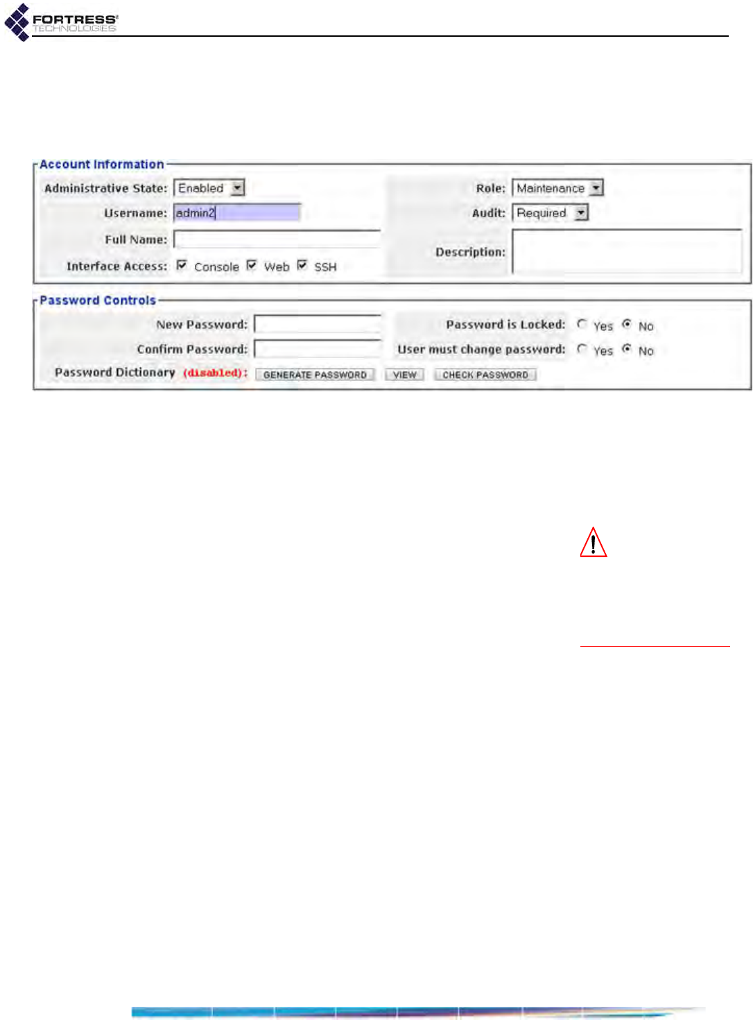
Bridge GUI Guide: Administrative Access
35
of the page, then Configure -> Administration from the menu
on the left.
2In the Administration screen’s Administrator Settings frame,
click NEW USER.
Figure 2.12. creating a new administrator account, all platforms
3In the Account Information frame, enter at least a Username
and optionally a Full Name and/or Description, and
configure any additional settings for the account. (Your
options are described in detail in sections 2.2.2.1through
2.2.2.6.)
CAUTION:
Make a
record of the pass-
word for future access
to the Bridge. After the
password is applied it
cannot be queried by
any means.
4In the Password Controls frame, establish a new password
for the account:
Click GENERATE PASSWORD to automatically generate a
password that complies with the complexity
requirements currently in effect (Section 2.2.1.8).
or
Enter a New Password that complies with the
complexity requirements currently in effect.
You can check the password against the list of words used
by the Bridge’s Password Dictionary function by clicking
Password Dictionary: CHECK PASSWORD. The message Not
Blacklisted will be returned if the entry passes the check;
Blacklisted! indicates that the entry failed the check and
cannot be used. If the Password Dictionary check is not in
effect it is labeled (disabled).
5Record and secure the new password for future reference.
You will need the password for subsequent access to the
Bridge and the network it secures.
6Optionally, in the same frame, you can lock the password or
require the administrator to change it when s/he first logs
on (described in detail in Section 2.2.2.7.)
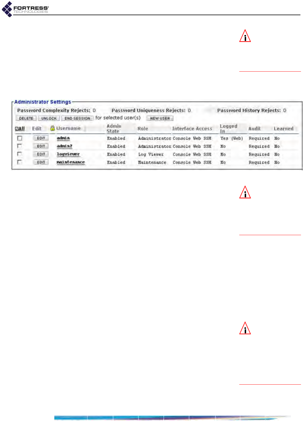
Bridge GUI Guide: Administrative Access
36
NOTE: You can
view but not edit
the list against which
passwords are checked
by clicking Password Dic-
tionary: VIEW.
You can optionally view current password complexity
requirements by clicking More Information in the upper right
of the Edit Password screen and then Password Complexity
Settings.
7Click APPLY in the upper right of the screen (or CANCEL the
creation of the new account).
The new account will be listed, in Advanced View, in
Administrator Settings on Configure -> Administration.
Figure 2.13. Advanced View
Administrator Settings
frame, all platforms
NOTE:
Refer to Sec-
tion 2.2.1.6 for de-
tails on configuring the
Bridge
to use a third-
party or Fortress RADI-
US server to authenticate
administrators.
When the Bridge is configured to authenticate administrators
through a third-party or Fortress user authentication database
(Authentication Method: RADIUS), administrators who log on
successfully through a user account are automatically added to
the Bridge’s local database of administrator accounts as
Learned accounts. (Refer to Section 2.2.1.6 for more on
administrative authentication methods.)
Up to ten such Learned accounts can be present. They appear
among configured accounts on the Admin Users page—and in
the local administrator database—with a Learned status of Yes.
Learned account credentials can be authenticated only by the
third-party RADIUS server or Fortress user authentication
database on which their accounts were originally configured. A
Learned administrator cannot log on to the Bridge through the
local administrator database until you convert the account to a
locally configured account (as indicated by a Learned state of
No).
NOTE: Once a
Learned account
has been converted to a
local configured ac-
count, it is completely
independent of the ac-
count in the authentica-
tion service from which
it was learned.
To convert a learned account to a configured account:
1Log on to the Bridge GUI through an Administrator-level
account and select ADVANCED VIEW in the upper right corner
of the page, then Configure -> Administration from the menu
on the left.
2In the Administrator Settings frame, locate the record for the
Learned (Yes) administrator whose account you want to
convert (the Username will match the administrator’s
RADIUS-server user name), and click the EDIT button to the
left of the record.
You need not make any changes to the account.

Bridge GUI Guide: Administrative Access
37
3Click APPLY in the upper right of the screen (or CANCEL the
conversion of the account).
The newly converted account will be listed, in Advanced View,
on Configure -> Administration with Learned state of No, and the
associated administrator will be allowed to log on (with valid
credentials).
Learned user names and passwords need not meet the
Bridge’s configured requirements for local administrative
accounts.
NOTE: If an ac-
count is the only
Enabled Administrator-
level account present,
you cannot change its
Administrative State to
Disabled or reconfigure
its Role.
2.2.2.9 Editing Administrative Accounts
You can reconfigure any setting for an individual administrative
account except for the Username.
1Log on to the Bridge GUI through an Administrator-level
account and select ADVANCED VIEW in the upper right corner
of the page, then Configure -> Administration from the menu
on the left.
2In the Administrator Settings frame, click the EDIT button to
the left of the account you want to edit.
3On the resulting Administration screen, enter new values for
those settings you want to configure. (Your options are
described in detail in sections 2.2.2.2 through 2.2.2.7.)
NOTE:
Changes to
the account you
are currently logged
onto will take effect the
next time you log on.
4Click APPLY in the upper right of the screen (or CANCEL your
changes).
Global administrative account logon behaviors and password
requirements can be edited through Configure -> Security, as
described in Section 2.2.1.
2.2.2.10 Deleting Administrative Accounts
You can delete any account in the Advanced View Administrator
Settings frame (Configure -> Administration), except for:
the preconfigured accounts: admin, logviewer and
maintenance
any account, if it is the only Administrator-level account with
an Administrative State of Enabled present on the Bridge
At least one account with the Role of Administrator (refer to
Section 2.2.2.3) must always be present and enabled on the
Bridge.
1Log on to the Bridge GUI through an Administrator-level
account and select ADVANCED VIEW in the upper right corner
of the page, then Configure -> Administration from the menu
on the left.
2In the Administrator Settings frame, click to place a check in
the box(es) to the left of the account(s) you want to
eliminate.
3Click DELETE in the upper left of the frame.
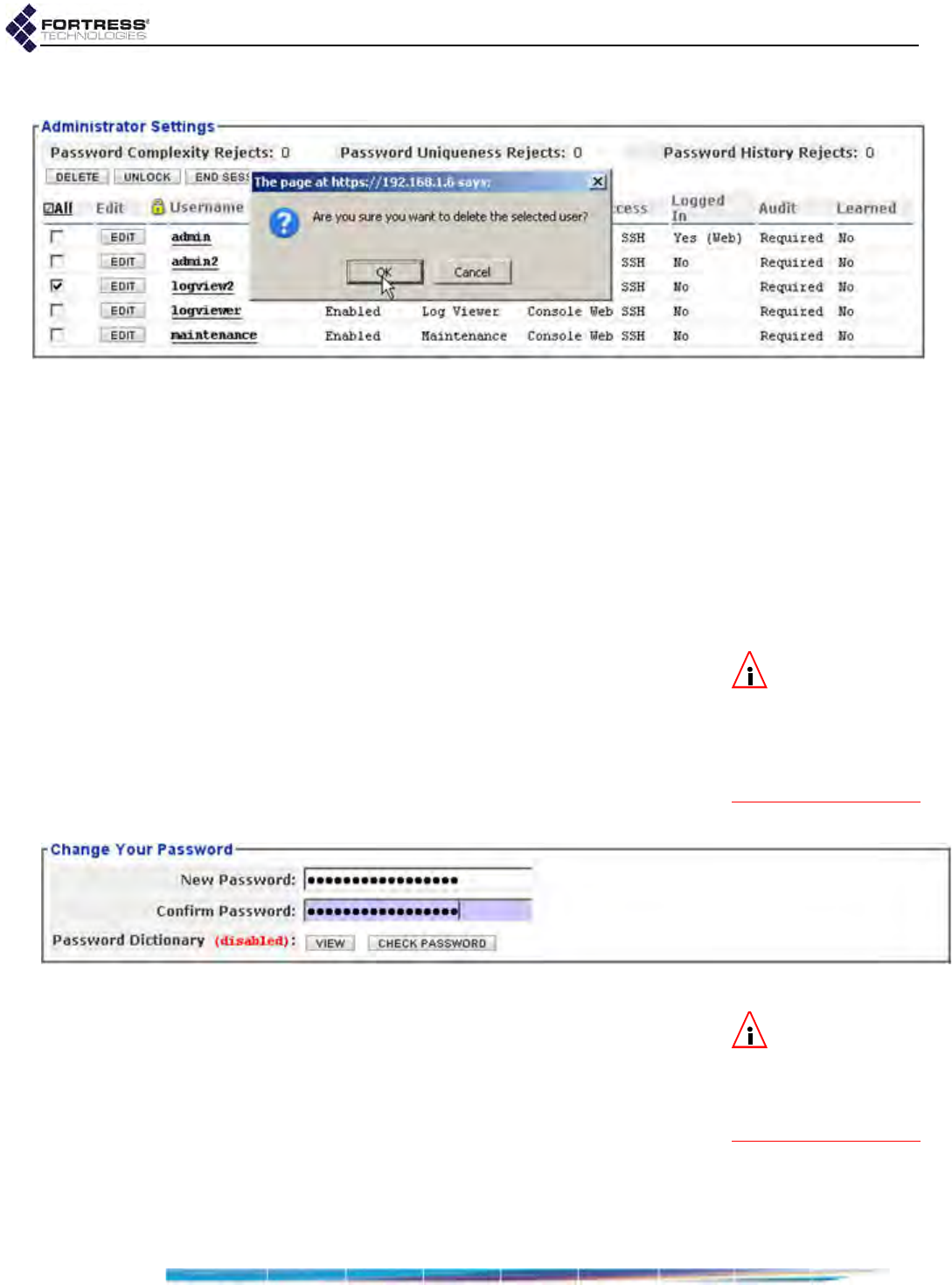
Bridge GUI Guide: Administrative Access
38
4Click OK in the confirmation dialog (or CANCEL the deletion).
Figure 2.14. deleting an administrator account, all platforms
The account will be removed from the Advanced View
Administrator Settings frame (Configure -> Administration).
2.2.2.11 Changing Administrative Passwords
Administrators with Administrator-level accounts can change
the password of any account, including their own, as described
in sections 2.2.2.7 and 2.2.2.9.
Provided the password is not locked (refer to Section 2.2.2.7),
administrators with Maintenance or Log Viewer accounts can
change their own passwords:
NOTE: The Change
Your Password op-
tion does not appear on
the Administration screen
when you are logged on
through an Administrator-
level account.
To change the account password from
Maintenance and Log Viewer accounts:
1Log on to the Bridge GUI through a Maintenance-level or
Log Viewer-level account and select Configure ->
Administration from the menu on the left.
2In the Change Your Password frame, enter a New Password
and re-enter it in Confirm Password.
Figure 2.15. changing the password from within a
Maintenance-
or
Log Viewer
-level account, all platforms
NOTE: You can
view but not edit
the list against which
passwords are checked
by clicking Password Dic-
tionary: VIEW.
You can optionally view current password complexity
requirements by clicking More Information in the upper right
of the Edit Password screen and then Password Complexity
Settings.
You can check the password against the list of words used
by the Bridge’s Password Dictionary function (refer to
Section 2.2.1.8) by clicking Password Dictionary: CHECK
PASSWORD. The message Not Blacklisted will be returned if
the entry passes the check; Blacklisted! indicates that the
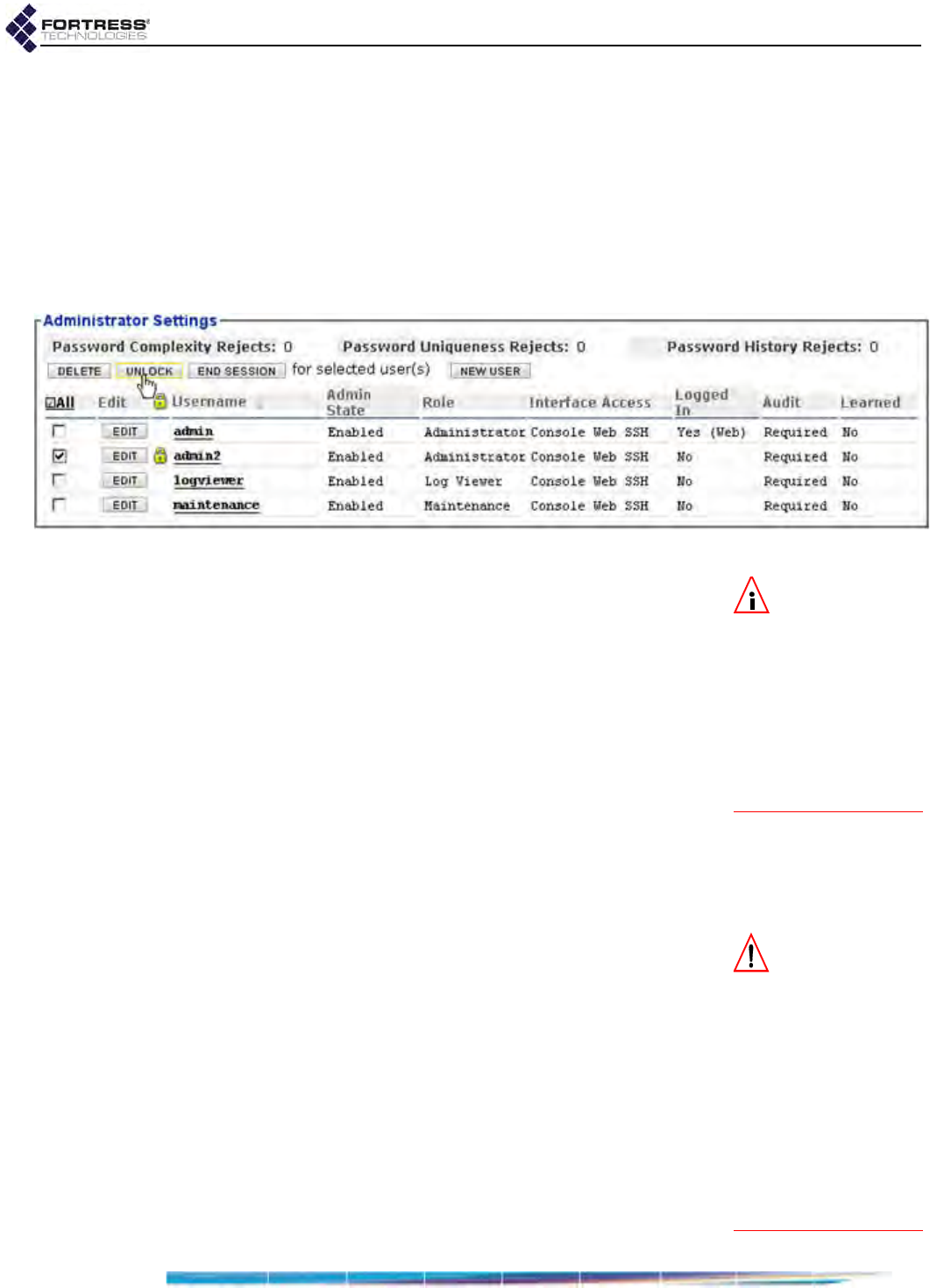
Bridge GUI Guide: Administrative Access
39
entry failed the check and cannot be used. If the Password
Dictionary check is not in effect it is labeled (disabled).
3Click APPLY in the upper right of the screen (or CANCEL the
change).
Role configuration options for administrative accounts are
described in detail in Section 2.2.2.3.
2.2.2.12 Unlocking Administrator Accounts
You can unlock administrator accounts in Advanced View only.
Figure 2.16. unlocking an administrator account, all platforms
NOTE: If no Admin-
istrator-level ac-
count is available, you
can unlock an account
only through a direct,
physical connection to
the Bridge’s Console
port, with the Bridge
CLI’s unlock command
(refer to the CLI Soft-
ware Guide).
1Log on to the Bridge GUI through an Administrator-level
account and select ADVANCED VIEW in the upper right corner
of the page, then Configure -> Administration from the menu
on the left.
2In the Administrator Settings frame, click to place a check in
the box(es) to the left of the account(s) you want to unlock.
3Click UNLOCK in the upper left of the frame.
4Click OK in the confirmation dialog (or CANCEL the action).
The account will be unlocked and the associated administrator
will be able to log on normally (with valid credentials).
The Lockout Duration can be set from 0 (zero) to 60 minutes; a
Lockout Duration of 0 (the default) disables the lockout function,
provided that Permanent Lockout is Disabled (the default).
CAUTION: If you
ignore the relevant
warning, you can lock
out all network access to
the Bridge by having the
administrator IP ACL
Enabled when there are
no IP addresses listed.
You can access the
Bridge in this case only
by a physical connection
to the Bridge’s Console
port (refer to the CLI
Software Guide)
2.2.3 Administrator IP Address Access Control
You can control remote administrative access to the Bridge by
restricting the IP addresses from which administrators are
permitted to log on.
When the Admin IP Access Control Whitelist is Enabled, only
those IP addresses present on the list will be permitted to
access the Bridge’s management interface remotely.
To control remote access by specified IP addresses:
1Log on to the Bridge GUI through an Administrator-level
account and select ADVANCED VIEW in the upper right corner
of the page, then Configure -> Access Control from the
menu on the left.
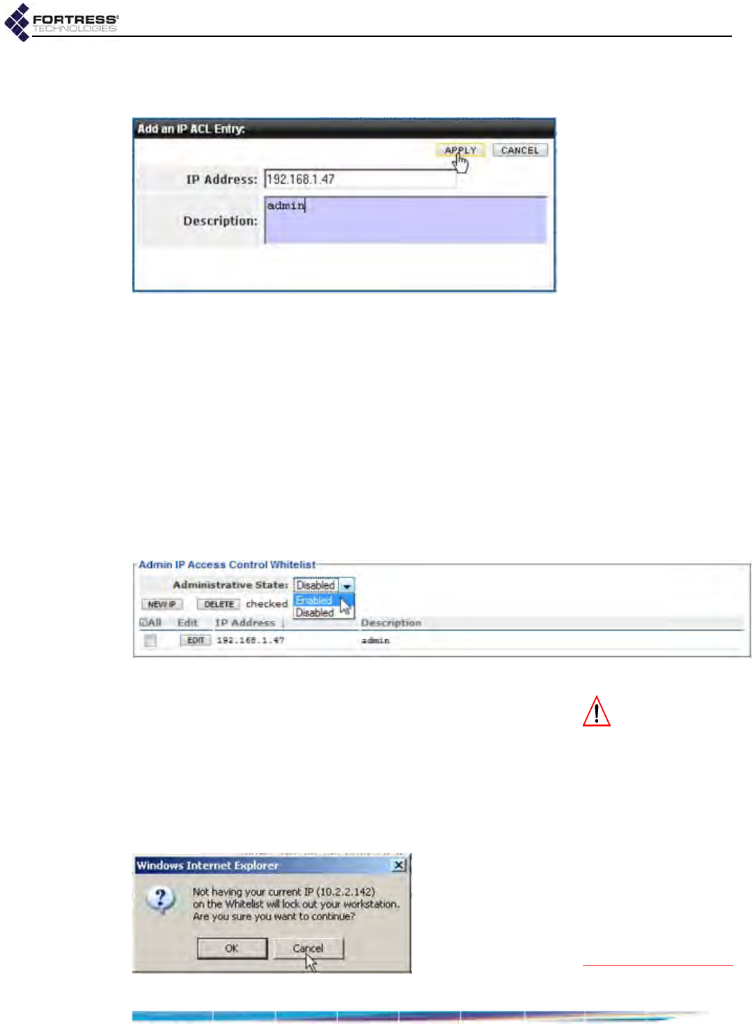
Bridge GUI Guide: Administrative Access
40
2In the resulting screen’s Admin IP Access Control Whitelist
frame, click NEW IP.
Figure 2.17. Advanced View
Add an IP ACL Entry
dialog, all platforms
3In the resulting Add an IP ACL Entry dialog, enter the IP
Address of the computer from which you are currently
logged on and, optionally, a Description for the entry. Then
click APPLY (or CANCEL the addition).
The IP address you added will be listed on the Admin IP
Access Control Whitelist.
4Repeat steps 2 and 3 for any additional IP addresses from
which you want to permit administrative access.
5When you have finished adding permitted IP addresses, in
the Admin IP Access Control Whitelist frame, in
Administrative State, click Enabled.
Figure 2.18. Advanced View
Admin IP Access Control Whitelist
frame, all platforms
CAUTION: If your
current IP address
is not on the administra-
tor IP ACL when you
Enable it or you delete
your address when the
list is already enabled,
and you do not Cancel
the change when
prompted, your session
will end and your cur-
rent IP address will be
blocked until it is added
to the list of permitted
addresses or the func-
tion is disabled.
6Click APPLY on the right of the frame.
If you navigate away from the screen without clicking
APPLY, the Administrative State will not be changed.
If you attempt to enable the Admin IP Access Control Whitelist
when the IP address you are currently logged on through is not
listed, a dialog warns that proceeding will lock the computer
you are currently using out of the Bridge’s management
interface.
Figure 2.19. Advanced View current IP address lockout dialog, all platforms

Bridge GUI Guide: Administrative Access
41
A dialog will also warn you if you are deleting your current IP
address from the list when it is already enabled (after you have
cleared the usual confirmation dialog).
Unless you want to prevent management access to the Bridge
from your current IP address, Cancel these changes.
The Admin IP Access Control Whitelist is Disabled by default,
and no IP addresses are listed.
If the Admin IP Access Control Whitelist is Enabled when there
are no IP addresses on the list, administrative access to the
Bridge will be possible only through a direct, physical
connection to the Bridge’s Console port (refer to the CLI
Software Guide).
2.2.4 SNMP Administration
In the Bridge GUI Advanced View, the Fortress Bridge can be
configured for monitoring through Simple Network
Management Protocol (SNMP) version 3.
The Fortress Management Information Bases (MIBs) for the
Bridge are included on the Bridge CD-ROM.
When SNMP v3 support is enabled, the SNMP v3 user
(FSGSnmpAdmin) access to the Bridge is authenticated via the
SHA-1 message hash algorithm as defined in RFC 2574, User-
based Security Model (USM) for version 3 of the Simple Network
Management Protocol (SNMPv3), using the specified
authentication passphrase. SNMP v3 privacy is secured via the
Advanced Encryption Standard with a 128-bit key (AES-128),
using the specified privacy passphrase.
SNMP v3 support is disabled by default.
When SNMP traps are enabled, the SNMP daemon running on
the Bridge detects certain system events and sends notice of
their occurrence to a server running an SNMP management
application, the network management system (NMS), or trap
destination.
SNMP traps are disabled by default, and no SNMP trap
destinations are configured (refer to Section 2.2.4.2).
Figure 2.20. Advanced View
SNMP frame
, all platforms

Bridge GUI Guide: Administrative Access
42
The settings that configure SNMP on the Bridge include:
SNMP v3 Support - enables/disables SNMP v3 user access.
When SNMP v3 Support is Enabled, the preconfigured
SNMP v3 user is permitted to access the Bridge, and new
passphrases should be configured in the SNMP v3 User
frame:
Username - identifies the v3 user, FSGSnmpAdmin.
Username cannot be changed.
NOTE: The default
Auth Passphrase is
FSGSnmpAdminPwd.
New Auth Passphrase and Confirm Auth Passphrase - an
authentication passphrase of 10–32 alphanumeric
characters (without spaces). You should change the
Auth Passphrase from the default if you enable SNMP v3
Support.
New Privacy Passphrase and Confirm Privacy
Passphrase - a passphrase of 10–32 alphanumeric
characters (without spaces). You must enter a Privacy
Passphrase if you enable SNMP v3 Support.
SNMP v3 Support is Disabled by default. Refer to Section
2.20 for detailed instructions.
SNMP Traps - enables/disables SNMP event notifications
forwarded to specified trap destinations.
When SNMP Traps are Enabled, you must configure SNMP
Trap Destinations before traps can be sent:
Trap Destination IP - IP Address of the NMS server
Comment - optional description of the trap destination
Refer to Section 2.2.4.2 for detailed instructions.
System Contact - establishes the E-mail address for the
Bridge’s administrative SNMP contact.
System Location - establishes a name for the location of the
Bridge-secured network.
System Description - provides an optional description of the
Bridge-secured system.
2.2.4.1 Configuring SNMP v3
If you enable SNMP v3 Support, you should specify and confirm
a New Auth Passphrase and a New Privacy Passphrase.
1Log on to the Bridge GUI through an Administrator-level
account and select ADVANCED VIEW in the upper right corner
of the page, then Configure -> Administration from the menu
on the left.
2Scroll down to the SNMP frame, and click Enabled for SNMP
v3 Support to enable SNMP v3 (or disable it by clicking
Disabled).
3In the same frame:
In New Auth Passphrase and Confirm Auth Passphrase,
enter an authentication passphrase of 10–32
alphanumeric characters (without spaces).

Bridge GUI Guide: Administrative Access
43
In New Privacy Passphrase and Confirm Privacy
Passphrase, enter a privacy passphrase for the user
(10–32 alphanumeric characters without spaces).
4In the same frame, optionally enter:
an E-mail address to serve as the SNMP System
Contact
a description of the System Location
a System Description
5Click APPLY in the upper right of the screen (or RESET
screen settings to cancel your changes).
2.2.4.2 Configuring SNMP Traps
You can create, edit and delete trap destinations regardless of
whether SNMP traps are enabled.
Traps will not be sent to configured destinations when SNMP
Traps are Disabled (the default).
To enable/disable SNMP traps:
1Log on to the Bridge GUI through an Administrator-level
account and select ADVANCED VIEW in the upper right corner
of the page, then Configure -> Administration from the menu
on the left.
2Scroll down to the SNMP frame, and click Enabled for SNMP
Traps to enable traps or Disabled to disable them.
3Click APPLY in the upper right of the screen (or RESET
screen settings to cancel your changes).
Table 2.2. Fortress SNMP Traps
event type event
status
the Gatewaya has started
a. In SNMP traps, the Bridge is identified as a “Gateway.”
the Gateway is active
the Gateway is down
change Access ID open window has closed
devices
a Secure Client has disconnected
all Secure Clients have disconnected
a Secure Client has idle timed out
a Secure Client has roamed
connections
the partnersb have reset
b. Partners are devices on the encrypted network
the clientsc have been reset
c. Clients are devices on the clear network
the sessionsd have reset
d. Sessions of devices on both the secure and clear networks
reset.
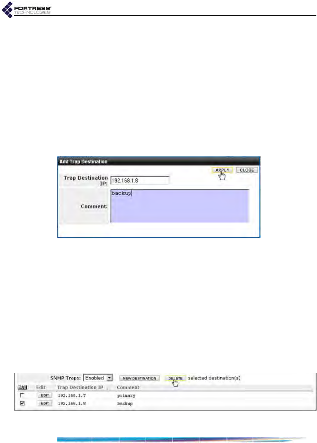
Bridge GUI Guide: Administrative Access
44
To create trap destinations:
1Log on to the Bridge GUI through an Administrator-level
account and select ADVANCED VIEW in the upper right corner
of the page, then Configure -> Administration from the menu
on the left.
2Scroll down to the SNMP frame, and click NEW DESTINATION.
3In the Add SNMP Trap Destination dialog:
In Trap Destination IP: enter the network address of an
SNMP network management system.
In Comment: optionally enter a comment for display with
the associated destination IP address.
4Click APPLY in the upper right of the screen (or CLOSE the
dialog to cancel your changes).
Configured traps are displayed in the SNMP Traps frame.
Figure 2.21. Advanced View
Add Trap Destination
dialog, all platforms
To edit a trap destination:
1Log on to the Bridge GUI through an Administrator-level
account and select ADVANCED VIEW in the upper right corner
of the page, then Configure -> Administration from the menu
on the left.
2Scroll down to the SNMP frame and click the EDIT button for
the trap destination you want to change.
3In the resulting Edit SNMP Trap Destination dialog:
In Destination IP address: enter a new address of an
SNMP network management system and/or revise the
optional Comment.
4Click APPLY in the upper right of the screen (or CLOSE the
dialog to cancel your changes).
Figure 2.22. deleting an SNMP trap, all platforms
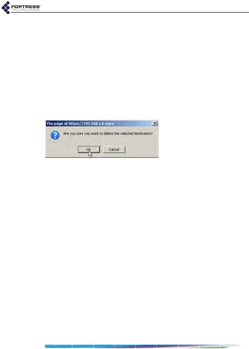
Bridge GUI Guide: Administrative Access
45
To delete a trap destinations:
1Log on to the Bridge GUI through an Administrator-level
account and select ADVANCED VIEW in the upper right corner
of the page, then Configure -> Administration from the menu
on the left.
2Scroll down to the SNMP frame and:
If you want to delete one or more selected destinations,
click to check the box(es) for those you want delete.
or
If you want to delete all destinations, click All to place a
check in all destination checkboxes.
3Click DELETE.
4Click OK in the confirmation dialog (or Cancel your deletion).
Figure 2.23. Advanced View deleting an SNMP trap confirmation dialog, all platforms
Your changes are reflected in the SNMP Trap Destinations
frame on the main Configuration -> SNMP screen.

Bridge GUI Guide: Network Configuration
46
Chapter 3
Network and Radio Configuration
3.1 Network Interfaces
CAUTION: All
Bridges in a mesh
network must run the
same Bridge software
version.
Multiple Bridges can be connected through their wired and/or
wireless interfaces to form fixed or mobile tactical mesh
networks and to bridge or extend the reach and availability of
conventional hierarchical networks.
Different models of Fortress Bridge chassis feature varying
numbers of user-configurable Ethernet ports. Fortress Bridges
can be additionally equipped with one to four independent
internal radios supporting various capabilities defined in the
IEEE (Institute of Electrical and Electronics Engineers)
802.11-2007 standard, or with no radios. On each radio internal
to a Bridge, up to four independent wireless interfaces, or Basic
Service Sets (BSSs), can be configured, up to a total of eight
per Bridge.
Alternatively, an ES210 Bridge can be dedicated to act as a
wireless client by configuring a single station (STA) interface on
its single internal radio.
Compare your Bridge’s model number (on the Administration
Settings screen under System Info.) to Table 1.1 on page 3 to
determine the number of Ethernet ports with which the Bridge
you are configuring is equipped and the number and type(s) of
radio(s) installed in it.
Fortress Bridge radios can connect to the radios of remote
Fortress Bridges to form mesh networks and, on separate
BSSs, serve as access points (APs) or access interfaces to
connect compatibly configured wireless devices to a wireless
LAN (WLAN) or to an FP Mesh access network.
On Bridges with more than one radio, the higher power radio(s)
dedicated to the higher frequency band (5 GHz, standard
equipment, or 4.4 GHz, military band) will generally be the
better choice for network bridging (or backhaul) links. In
Bridges with two radios (ES520 and ES820), these are
Radio 2. In the four-radio ES440, Radio 2, Radio 3 and Radio 4
are all in this category.

Bridge GUI Guide: Network Configuration
47
In Fortress Bridges equipped with any number of radios, the
standard-equipment Radio 1 is a dual-band 802.11a/g (or
802.11a/g/n) radio. Radio 1’s 802.11g capability typically
indicates its use to provide wireless access to devices within
range.
You can configure the Bridge's network interfaces to meet
various deployment and security requirements. Ethernet port
configuration is covered in Section 3.7. Creating and
configuring radio interfaces are described in Section 3.3.4
(BSS interfaces) and Section 3.3.5 (WLAN client interfaces).
3.2 Bridging Configuration
NOTE: FastPath
Mesh and STP
Bridging Modes are in-
compatible with the
Bridge’s VLAN func-
tion (Section 3.9).
Each Bridge can maintain simultaneous network links with up
to fifty other Bridges, so that up to fifty-one directly linked
Fortress Bridges can be present on a given network. Many
more Bridges can belong to a more widely deployed mesh
network encompassing nodes linked indirectly through other
nodes.
Networked radios must:
use the same radio frequency band (Section 3.3.2.2)
be set to the same channel (Section 3.3.2.3)
The BSSs that comprise the network must:
be enabled for bridging (Section 3.3.4.3)
be configured with the same SSID (Section 3.3.4.2)
Wireless bridging links must be formed over Fortress-secured
interfaces. When a BSS’s Wireless Bridge setting is Enabled,
the BSS’s Fortress Security setting is automatically fixed on
Enabled, the Wi-Fi Security setting is automatically fixed on
Disabled, and the fields are greyed out (refer to Section
3.3.4.3).
When licensed to do so, the Bridge can manage bridging links
and route network traffic using Fortress’s FastPath Mesh (FP
Mesh) tactical mobile networking. Alternatively, Spanning Tree
Protocol (STP) can be used for mesh link management without
a license.
Both protocols enable the deployment of self-forming, self-
healing secure networks, and both prevent bridging loops while
providing path redundancy.
STP prevents network loops by selectively shutting down some
mesh network links.
FastPath Mesh maintains the availability of every mesh
connection and additionally provides optimal path routing of
network traffic, along with independent IPv6 mesh addressing
and DNS (Domain Name System) distribution functions to

Bridge GUI Guide: Network Configuration
48
support the mesh network and user controls to configure and
tune it.
NOTE: FastPath
Mesh and STP link
management are mutu-
ally incompatible. Net-
worked Bridges must all
be configured to use the
same Bridging Mode.
Unless the network can be physically configured to eliminate
any possibility of bridging loops (multiple OSI [open systems
interconnection] layer-2 paths to the same device), either
FastPath Mesh or STP must be used when Bridges are deployed
in a mesh network.
Supported FastPath Mesh and STP network topologies are
illustrated and described in detail in Chapter 1.
3.2.1 FastPath Mesh Bridging
Nodes on a FastPath Mesh network are of two basic types:
Mesh Point (MP) - a Fortress Bridge with FastPath Mesh
enabled
Non-Mesh Point (NMP) - any node that is not an MP
FP Mesh nodes can connect over their Ethernet ports or radio
BSSs. An FP Mesh interface must be configured for the type of
connection it provides:
MPs connect to other MPs only on Core interfaces.
NMPs connect to MPs only on Access interfaces
A given interface can be of only one type; so MPs and NMPs
cannot share an interface. Per-port FastPath Mesh Mode
settings for radio BSSs and Ethernet ports are described in
sections 3.3.4.4 and 3.7.3, respectively.
All MPs on a given FP Mesh network are peers. Directly
connected MPs are neighbors.
An MP that serves as a link between the FP Mesh network and
a conventional hierarchical network is a Mesh Border Gateway
(MBG).
An FP Mesh network presents to NMPs as a flat, OSI layer-2
network, while optimizing operations to eliminate inefficiencies
Table 3.1. STP Networks Compared to FastPath Mesh
function STP FP Mesh
self-forming supported supported
self-healing supportedasupported
end-to-end encryption supported supported
all paths available at all times not supported supported
optimal path selection not supported supported
automatic IPv6 mesh addressing not supported supported
independent DNS and .ftimesh.local domain not supported supported
configurable network and neighbor cost weighting not supported supported
a. except for STP root node

Bridge GUI Guide: Network Configuration
49
inherent in layer-2 networks, including advance ARP resolution
and streamlined broadcast and multicast handling to
significantly reduce broadcast traffic.
FP Mesh enables each node to use all mesh network links and
to route traffic on the optimal path by computing per-hop costs,
based on link conditions, and end-to-end costs, based on
cumulative per-hop costs. System and neighbor cost weighting
are user configurable (refer to sections 3.2.1.5 and 3.2.1.6).
Any node in an FP Mesh network can be reached via:
MAC (media access control) address, as in conventional
hierarchical networks
IPv4 address, if IPv4 is in use for the network
any IPv6 address locally generated for or assigned to the
node, including RFC-4193 and local- and global-scope
addresses
FQDN (fully qualified domain name), if servers internal to
FP Mesh network MPs are providing network DHCP
(Dynamic Host Control Protocol) and DNS services (refer
to Section 3.6).
NOTE: The For-
tress Bridge’s in-
ternal DNS and DHCP
servers are covered in
Section 3.6.
IPv4 Addressing and Name Resolution
IPv4 is enabled by default on the Bridge (refer to Section
3.4.2.1). Although FastPath Mesh functionality does not require
IPv4, it fully supports standard IPv4 addressing for all network
nodes (MPs and NMPs).
The DHCP and DNS servers internal to the Fortress Bridge can
be enabled on any Mesh Point. These severs provide virtually
configuration-free DHCP and DNS services for Non-Mesh
Points. FastPath Mesh operates best when the DNS servers
internal to all network MPs are enabled (the default), and the
DHCP server on one MP (or a small set of MP DHCP servers)
is enabled to provide network DHCP service(s).
Third-party external DHCP and DNS servers can be used with
FP Mesh but require extensive configuration. Furthermore, the
recommended Fortress internal server deployment uses far
fewer network resources because it does not allow DNS
network broadcast queries to enter the mesh from every NMP.
Only NMPs are provided DHCP service. IPv4 addresses must
be manually configured on FastPath Mesh Points (refer to
Section 3.4.2.1).
IPv6 Addressing, Namespace and Name Resolution
IPv6 is always enabled on the Bridge and every MP thus has a
link local IPv6 address (refer to Section 3.4.2.2). FP Mesh fully
supports standard IPv6 addressing for all network nodes (MPs
and NMPs), including locally assigned and local- and global-
scope addresses, as well as multiple IPv6 routers and
associated global prefixes.

Bridge GUI Guide: Network Configuration
50
Additionally, FastPath Mesh functionality itself provides
automatic IPv6 addressing without the need for a DHCP server
and name distribution within the network without the need for a
DNS server.
To provide independent IPv6 addressing and facilitate optimal
network traffic routing, FP Mesh generates an RFC-4193
Unique Local IPv6 Unicast Address (a.k.a., unique local
addresses or ULAs) for every MP and supports up to sixteen
IPv6-address prefixes using RFC-2461 Neighbor Discovery.
Figure 3.1. Advanced View
Bridging Configuration
frame,
Administration
screen, all platforms
FP Mesh Configuration Settings
Once the Bridge’s radio is enabled (Section 3.3.2.1) and a
bridging-enabled BSSs is created and configured on it (Section
3.3.4), the Bridge will act as a Mesh Point in a wireless
FastPath Mesh network, automatically connecting to
compatibly configured MPs via their automatically generated
IPv6 addresses, without additional FP Mesh configuration.
CAUTION: For-
tress-protected
networks are not fully
secured until all precon-
figured administrative
passwords and the Ac-
cess ID have been
changed from their de-
faults (sections 2.2.2.7
and 4.1.17, respectively).
Sections 3.2.1.1 through 3.2.1.7 describe the complete settings
for configuring FastPath Mesh networking. The first four
settings (in sections 3.2.1.1–3.2.1.4), are located in two places
in the Bridge GUI:
Configure -> Administration -> Bridging Configuration
Configure -> FastPath Mesh -> Global Settings
Network Cost settings (Section 3.2.1.5) are present only
among the FP Mesh settings on the Administration screen,
while Neighbor Cost and Multicast Group settings (sections
3.2.1.6 and 3.2.1.7) are present only on the FastPath Mesh
screen.
Step-by-step instructions for changing FP Mesh bridging
settings appear on page 53, following the descriptive sections
below.
NOTE: The Bridge
Priority setting on
Configure
->
Adminis-
tration
->
Bridging Con-
figuration
applies only to
STP bridging and is
greyed out when Fast-
Path Mesh is selected.
3.2.1.1 FastPath Mesh Bridging Mode
The Bridging Mode setting enables FastPath Mesh and the rest
of the settings that configure it, described below.
FastPath Mesh is available for selection only when the feature
has been licensed on the Fortress Bridge: refer to Section 6.3.
3.2.1.2 Fortress Security
For FP Mesh, you can choose to globally enable or disable
end-to-end Fortress Security for the Core interface connections

Bridge GUI Guide: Network Configuration
51
between FastPath MPs. When Enabled (the default), traffic
between MPs is subject to Fortress’s Mobile Security Protocol
(MSP), as configured on the Bridge itself (refer to Section 4.1).
3.2.1.3 Mobility Factor
To facilitate node mobility in the FP Mesh network, Mobility
Factor adjusts the frequency at which the costs of data paths to
neighbor nodes are sampled so that cost changes can be
transmitted to the network. The higher the Mobility Factor, the
more frequent is the cost sampling.
NOTE: All MPs in
the FP Mesh net-
work should use the
same mobility factor.
Enter the highest relative speed of nodes in the network, in
miles per hour, as the Mobility Factor for all the MPs in the FP
Mesh network. For example, if nodes could move at
approximately 10 mph and in opposite directions, their highest
relative speed is 20 mph: enter 20 for Mobility Factor.
Set the Mobility Factor between 1 (the appropriate setting for a
stationary node) and 60. The default is 30.
3.2.1.4 Mesh Subnet ID
When FP Mesh is enabled, a Unique Local IPv6 Unicast
Address, as defined in RFC 4193, is generated for the Fortress
Bridge Mesh Point in the format:
| 7 bits |1| 40 bits | 16 bits | 64 bits |
+--------+-+------------+-----------+----------------------------+
| Prefix |L| Global ID | Subnet ID | Interface ID |
+--------+-+------------+-----------+----------------------------+
Prefix - FC00::/7 identifies the address as a Local IPv6
unicast address
L - 1 if the prefix is locally assigned (0 value definition t.b.d.)
Global ID - pseudo-randomly allocated 40-bit global
identifier used to create a globally unique prefix
Subnet ID - 16-bit subnet identifier
Interface ID - 64-bit Interface ID
The subnet ID portion of the RFC-4193 address will facilitate
network segmentation in a future release of FastPath Mesh.
3.2.1.5 Network Cost Weighting
CAUTION: The de-
fault cost equa-
tion values are optimal
for FP Mesh implemen-
tation. Ill-considered
changes can easily affect
network behavior ad-
versely.
Traffic on an FP Mesh network is routed along the least costly
path to its destination. You can rebalance how the FP Mesh
network computes the throughput and latency costs of
available data paths by specifying new values for a and/or b in
the FP Mesh cost equation:
cost = a *(1/CLS) + b*(Q/CLS) + U
...in which:
CLS - (Current Link Speed) is the time-averaged link speed,
as measured in bits per second.
Q - is the time-averaged current Queue depth, as
measured in bits.

Bridge GUI Guide: Network Configuration
52
U - is the user defined per-interface cost offset, which
allows you to configure one link to be more costly than
another. Any non-negative integer between 0 (zero) and
4,294,967,295 can be defined (for configuration
information, refer to Section 3.3.4.4 for wireless and
Section 3.7.3 for Ethernet interface controls).
a and b - are device-wide user defined constants that
correspond to throughput and latency, respectively. Any
non-negative integer between 0 (zero) and 65,535 can be
defined.
As a rule, a higher value of the constant a, Throughput Cost
Weighting, improves overall throughput, while a higher value of
b, Latency Cost Weighting, reduces latency. The default for both
is 1.
3.2.1.6 Neighbor Cost Overrides
The cost of reaching a neighbor node (another Mesh Point
directly linked to the current MP) on an FP Mesh network is the
cost associated with the interface used to reach the node. You
can override the interface cost for a particular neighbor by
specifying a fixed cost for that node.
The neighbor for which the cost override is specified should be
configured with a reciprocal neighbor cost, of the same value,
specified for the current MP. Asymmetric neighbor cost
overrides are not recommended.
NOTE: If more
than one cost over-
ride is specified for the
same neighbor by dif-
ferent identifiers, only
the cost associated with
the highest address-
type on the list shown
(at left) will be applied.
To configure a neighbor cost override, you must identify the FP
Mesh interface the neighbor connects to and specify the node
by any one of:
MAC address
IP address
RFC-4193 IPv6 address
IPv4 address
hostname
NOTE: A node is
assumed to have a
only one IPv6 unique lo-
cal address. If different
costs are configured for
the same neighbor by
more than one IPv6 ad-
dress, applied cost is
unpredictable.
Specify a given neighbor’s cost override by only one address
identifier, in non-negative numbers between 1 and
4,294,967,295; or specify max. The higher the cost value, the
less likely the neighbor will be used to route network traffic. A
neighbor with a cost of max will never be used to route traffic.
You can configure Neighbor Costs for devices that are not
currently neighbor MPs, or even peers. If the specified node
appears as or becomes a neighbor, the configured cost will be
applied.
3.2.1.7 Multicast Group Subscription
FastPath MPs automatically subscribe/unsubscribe to
multicast streams on behalf of NMPs by snooping IP multicast
control messages (IGMP and MLD3) on mesh Access
interfaces.
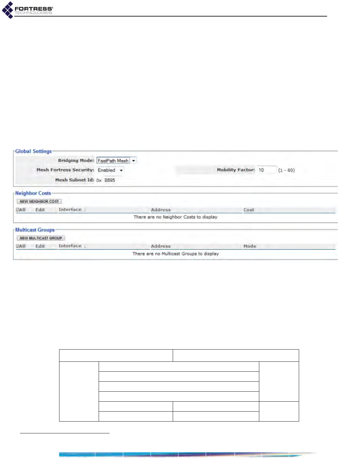
Bridge GUI Guide: Network Configuration
53
You can also force MPs to join or leave specific multicast
groups, if you need to support non-IP multicast groups or a
device on an Access interface that doesn’t implement IGMP/
MLD, or for testing/debugging purposes.
To subscribe to a multicast group, you must identify the FP
Mesh interface for the stream and specify the multicast
address for the group by MAC or IP address. MPs can
subscribe as multicast listeners, talkers or both (the default).
You can observe the multicast groups to which the MP is
currently subscribed (whether learned or configured) on
Monitor -> Mesh Status -> Multicast Groups (described in
Section 5.8.5). You can observe and flush the Multicast/
Broadcast Forwarding table on the same page.
Figure 3.2. Advanced View
FastPath Mesh Settings
screen, all platforms
3.2.1.8 Configuring FastPath Mesh Settings:
Only Bridging Mode can be configured in both Bridge GUI
views. Other FastPath Mesh bridging settings are accessible
only in Advanced View.
Basic FastPath Mesh settings are located in two places in the
Bridge GUI, more advanced settings appear on only one
Advanced View screen, as shown in Table 3.2.
3. Internet Group Management Protocol, Multicast Listener Discovery, Multicast Router Discovery
Table 3.2. FastPath Mesh Bridging Settings
Administration screen FastPath Mesh screen
Bridging
Configura-
tion frame
Bridging Mode
Global
Settings
frame
Mesh Fortress Security
Mobility Factor
Mesh Subnet ID
Throughput Cost Weighting Neighbor Costs individual
frames
Latency Cost Weighting Multicast Groups

Bridge GUI Guide: Network Configuration
54
1Log on to the Bridge GUI through an Administrator-level
account.
2If you are configuring any setting beyond Bridging Mode,
click ADVANCED VIEW in the upper right corner of the page.
(If not, skip this step.)
3Navigate to a Bridge GUI screen and frame through which
the setting(s) you want to configure can be accessed:
Configure -> Administration -> Bridging Configuration
Configure -> FastPath Mesh -> Global Settings or
Neighbor Costs or Multicast Groups
(Refer to Table 3.2.)
4Enter new values for any settings you want to configure in
the Bridging Configuration or Global Settings frames
(described in sections 3.2.1.1 through 3.2.1.5, above), and
click APPLY in the upper right of the screen (or RESET screen
settings to cancel your changes).
5To configure neighbor cost overrides:
In the FastPath Mesh screen’s Neighbor Costs frame:
If you want to specify a new MP for a cost override:
Click NEW NEIGHBOR COST.
In the Add a new Neighbor Cost dialog, specify the
Core interface through which the neighbor connects
(or will connect) to the current MP:
From the Interface dropdown, select a BSS
currently configured on (one of) the MP’s
radio(s) or one of the MP’s Ethernet ports.
or
Leave Interface at the default, New BSS, and
enter a valid BSS Name, as it will be (or is
currently) configured on (one of) the MP’s
radio(s).
Enter an Address for the neighbor: its MAC or IPv4
or IPv6 address or its host name.
Enter the Cost, from 1 to 4,294,967,295, you want
to configure for the neighbor (refer to Section
3.2.1.6).
Click APPLY in the dialog (or CANCEL the action).
NOTE: You cannot
change the Inter-
face or Address for an ex-
isting Neighbor Costs
entry. If these values
have changed, delete
the neighbor’s entry and
recreate it with the new
value.
and/or
If you want to change an existing cost override:
Click the EDIT button for the neighbor’s entry.
In the Edit a Neighbor Cost dialog, enter a new value
between 1 to 4,294,967,295 for Cost.
Click APPLY in the dialog (or CANCEL the action).
6To subscribe to multicast groups:
In the FastPath Mesh screen’s Multicast Groups frame:

Bridge GUI Guide: Network Configuration
55
If you want to subscribe to a new multicast group:
Click NEW MULTICAST GROUP.
In the Add a Multicast Group dialog, specify the
Access interface on which the current MP will
subscribe to the multicast group:
From the Interface dropdown, select a BSS
currently configured on (one of) the MP’s
radio(s) or one of the MP’s Ethernet ports.
or
Leave Interface at the default, New BSS, and
enter a valid BSS Name, as it will be (or is
currently) configured on (one of) the MP’s
radio(s).
Enter a MAC or IPv4 or IPv6 Address for the
multicast group.
From the Mode dropdown, select whether the MP is
subscribing is as a multicast Listener, Talker or Both
(refer to Section 3.2.1.7).
Click APPLY in the dialog (or CANCEL the action).
and/or
If you want to change the Mode of an existing
subscription:
Click the EDIT button for the subscription’s entry.
In the Edit a Multicast Group dialog, select a new
value for Mode (you cannot change the Interface or
Address).
Click APPLY in the dialog (or CANCEL the action).
To delete Neighbor Costs or Multicast Groups:
You can delete a single entry or all entries in either list.
1Log on to the Bridge GUI through an Administrator-level
account and select ADVANCED VIEW in the upper right corner
of the page, then Configure -> FastPath Mesh from the menu
on the left.
2In the FastPath Mesh screen’s Neighbor Costs or Multicast
Groups frame:
If you want to delete a single entry, click to place a
check in the box beside it; then the DELETE button
above the list.
or
If you want to delete all entries, click All to place a
check in all entries’ boxes; then click the DELETE button
above the list.
The relevant list reflects the deletion(s).

Bridge GUI Guide: Network Configuration
56
3.2.2 STP Bridging
NOTE: Settings
other than Bridge
Priority on Configure ->
Administration -> Bridg-
ing Configuration apply
only to FastPath Mesh
bridging and are greyed
out when STP is select-
ed for Bridging Mode.
When STP is used for link management, the Fortress Bridge
can connect to other Fortress Bridges to form mesh networks
and, on separate BSSs, simultaneously serve as access points
(APs) to connect compatibly configured wireless devices to a
wireless LAN (WLAN).
STP is selected for Bridging Mode by default.
Bridging BSSs
BSSs enabled for wireless bridging automatically form STP
mesh network connections with compatibly configured bridging
BSSs on other Fortress Bridges.
NOTE: Fortress Se-
curity is Enabled
for WDS-enabled BSSs,
Wi-Fi Security is Dis-
abled, and these fields
are greyed out.
On Bridges equipped with multiple radios, the radio(s) fixed on
the 5 GHz 802.11a frequency band will generally be the most
appropriate for the bridging function. (These include Radio 2 in
the ES520 and ES820 and Radio 2, Radio 3 and Radio 4 in the
ES440.) BSSs configured on these radios are therefore
Enabled for WDS by default.
Access Point BSSs
Under STP link management, a BSS on which bridging is
disabled is acting as a conventional wireless AP.
On Bridges equipped with multiple radios, Radio 1 is generally
the better choice for the AP function, because it can be
configured to use the 2.4 GHz 802.11g frequency band. By
default, BSSs configured on Radio 1 are therefore Disabled for
WDS.
Any wireless device within range of the Bridge’s radio can
connect to the Bridge-secured WLAN, if the connecting device:
is using the same RF band and channel as the Bridge radio
is using the same SSID as an AP BSS configured on the
Bridge
successfully meets all security requirements for connecting
to that BSS, if the BSS is configured to enforce security
measures
One of the Bridges in the network must act as the root switch in
the STP configuration. If a given root becomes unavailable, the
root role can be assumed by another Bridge in the network.
The network can experience significant traffic disruption in this
event, until the new STP root node has been established.
You can configure the order in which each Bridge in the
network will assume the STP root role, should Bridge(s) ahead
of it in the priority list become unavailable. The role of root is
taken by the Bridge in the network with the lowest STP Bridge
Priority number.
When the Bridge is in STP Bridging Mode, STP must be enabled
across all devices on the Bridge-secured network.

Bridge GUI Guide: Network Configuration
57
Figure 3.3. Simple View
Bridging Configuration
frame,
Administration
screen, all platforms
3.2.2.1 Configuring STP Bridging:
1Log on to the Bridge GUI through an Administrator-level
account and select Configure -> Administration from the
menu on the left.
NOTE: If net-
worked Bridges all
have the same priority
number, their MAC ad-
dresses are used, lowest
to highest, to establish
STP root priority.
2In the Bridging Configuration frame:
In Bridging Mode: select STP to enable Spanning Tree
Protocol.
In Bridge Priority: optionally enter a new STP root
numbers between 0 and 65535 are valid. The default is
49152.
3Click APPLY in the upper right of the screen (or RESET
screen settings to cancel your changes).
3.3 Radio Settings
Different Fortress Bridge models can be variously equipped
with one to four independent internal radios supporting various
802.11 capabilities, or with no radios.
Compare your Bridge’s model number (on the Administration
Settings screen under System Info.) to Table 3.3 above to
determine the number of and type of radio(s) with which the
Bridge you are configuring is equipped. On Bridge GUI Radio
Settings screens, configuration settings for 4.4 GHz military
band radios are also identified as such.
Table 3.3. Fortress Bridge Model Radios
series
basic
model # of
radios radio
label standard
equipment default
band standard
model # 4.4 GHz
option 4.4 GHz
model #a
ES
ES820 2
Radio 1 802.11a/g/n 802.11g ES820-35 no n/a
Radio 2 802.11a/n 802.11a no
ES520 2
Radio 1 802.11a/g 802.11g ES520-35 no ES520-34
Radio 2 802.11a 802.11a yes
ES440 4
Radio 1 802.11a/g/n 802.11g
ES440-3555
no
n/a
Radio 2–
Radio 4 802.11a/n 802.11a no
ES210 1
Radio 1 802.11a/g/n 802.11a ES210-3 no n/a
FC
FC-
X
0n/a
a. Refer to Section 1.3.1.1 for more on ES-series model numbers.

Bridge GUI Guide: Network Configuration
58
Each radio installed in a Fortress Bridge can be configured with
up to four BSSs, which can serve either as bridging interfaces
networked with other Fortress Bridges or as access interfaces
for connecting wireless client devices. Refer to Section 3.3.4
for details on radio BSS configuration.
Alternatively, an ES210 Bridge can be dedicated to act as a
wireless client by configuring a single station (STA) interface on
its single internal radio. Refer to Section 3.3.5 for details on
radio STA configuration.
3.3.1 Advanced Global Radio Settings
Advanced Global Radio Settings apply to all radios internal to
the Bridge and are available only in the Bridge GUI Advanced
View.
3.3.1.1 Radio Frequency Kill
The Kill All RF setting turns the radio(s) installed in the Bridge
off (Enabled) and on (Disabled).
The default Kill All RF setting is Disabled, in which state the
Bridge receives and transmits radio frequency signals normally.
You can also enable/disable RF kill through Fortress Bridge
chassis controls (refer to the Fortress Hardware Guide for the
Bridge you are configuring).
3.3.1.2 Radio Distance Units
The increment used to set Distance for the Bridges’ radio(s)
(refer to Section 3.3.2.7) is configured globally in Radio Units:
Metric - (the default) the Distance setting is configured in
kilometers.
English - the Distance setting is configured in miles.
3.3.1.3 Country of Operation
By default, the following countries and territories are available
for selection:
American Samoa
Austria
Belgium
Bosnia Herzegovina
Bulgaria
Canada
Croatia
Cyprus
Czech Republic
Denmark
Estonia
Finland
France
Germany
Greece
Guam
Hungary
Iceland
Ireland
Italy
Kosovo
Latvia
Liechtenstein
Lithuania
Luxembourg
Macedonia
Malta
Mexico
Montenegro
Netherlands
Northern Mariana Islands
Norway
Poland
Portugal
Romania
Saudi Arabia
Serbia
Slovakia
Slovenia
Spain
Sweden
Switzerland
Turkey
United Arab Emirates
United Kingdom
United States
US Minor Outlying Islands
US Virgin Islands

Bridge GUI Guide: Network Configuration
59
When Country is licensed on the Bridge (Section 6.3),
additional countries are available for selection.
To allocate bandwidth and prevent interference, radio
transmission is a regulated activity, and different countries
specify hardware configurations and restrict the strength of
signals broadcast on particular frequencies according to
different rules.
While some countries develop such regulations independently,
national regulatory authorities more often adopt an established
set of rules in common with other countries in the same region.
Whether used in common by multiple countries or by a single
country, a regulatory domain is distinguished by a single set of
rules governing radio devices and transmissions.
In order to comply with the relevant regulatory authority, you
must establish the Bridge’s regulatory domain by identifying the
country in which the Bridge will operate. Bridge software
automatically filters the options available for individual radio
settings (Section 3.3.2) according to the requirements of the
relevant regulatory domain as they apply specifically to the
Bridge’s internal radios.
In some of the countries on the default Country Code list, radios
using the 802.11a frequency band will have no compliant
channels available unless Advanced Radio operation has been
licensed on the Bridge. (Refer to Section 3.3.2 for more detail
on radio operation with and without an Advanced Radio license
and to Section 6.3 for licensing information.)
By default, the United States is selected as the Bridge’s country
of operation, and the rules of the Federal Communication
Commission (FCC) regulatory domain dictate available radio
settings in the 5 GHz 802.11a and the 2.4 GHz 802.11g
frequency bands.
The 4.400 GHz–4.750 GHz frequency range is regulated by
the United States Department of Defense, rather than by the
FCC. Use of military band radios is strictly forbidden outside of
U.S. military applications and authority. On a Bridge with one or
more 4.4 GHz radios installed, United States is selected as the
Bridge’s country of operation and the setting cannot be
changed.
3.3.1.4 Environment Setting
It is common for regulatory domains to restrict certain channels
to indoor-only use. In order for the Bridge’s radio(s) to comply
with such requirements, you must specify whether the Bridge is
operating Indoors or Outdoors (the default).
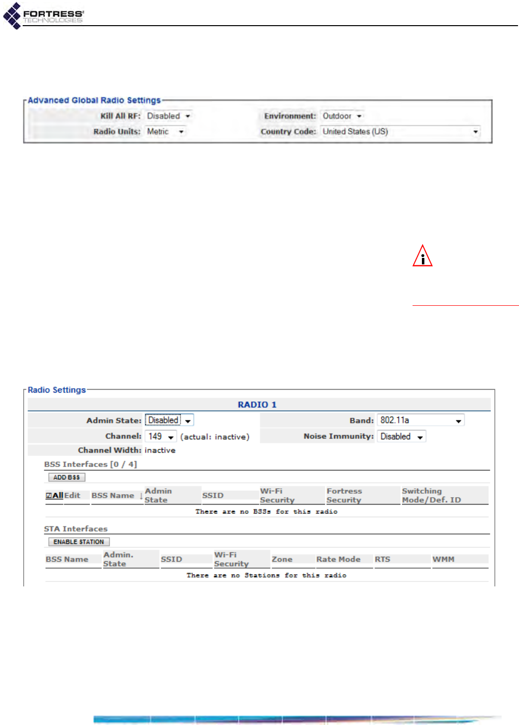
Bridge GUI Guide: Network Configuration
60
In many regulatory domains, including the Bridge’s FCC
domain, additional channels are available for selection (Section
3.3.2.3) when Environment is set to Indoors.
Figure 3.4. Advanced View
Advanced Global Radio Settings
frame, all radio-equipped platforms
3.3.1.5 Configuring Global Advanced Radio Settings
1Log on to the Bridge GUI through an Administrator-level
account and select ADVANCED VIEW in the upper right corner
of the page, then Configure -> Radio Settings from the menu
on the left.
NOTE: You must
reboot the Bridge
in order for a change to
Environment or Country
Code to take effect.
2In the Radio Settings screen’s Advanced Global Radio
Settings frame, use the dropdown menus to specify new
values for the setting(s) you want to change (described
above).
3Click APPLY in the upper right of the screen (or RESET
screen settings to cancel your changes).
3.3.2 Individual Radio Settings
The remaining settings that affect radio operation are
configured, per radio, in the Radio Settings frame.
Figure 3.5. Simple View
RADIO 1 Radio Settings
frame, all radio-equipped platforms
As determined by your Country Code selection (under Global
Radio Settings and described in Section 3.2), regulatory domain
requirements can affect an individual radio’s operational state
and Radio Band setting as well as determine available Channel
and TxPower options (refer to 3.3.2.3 and 3.3.2.6).

Bridge GUI Guide: Network Configuration
61
NOTE: If you
change the Coun-
try Code in effect on the
Bridge to a domain in
which current radio set-
tings are not permitted,
the relevant value(s)
will revert to default(s),
and reconfiguration op-
tions will be confined to
permissible values.
In addition, the Bridge uses your entries for Network Type and
Antenna Gain (refer to sections 3.3.2.4 and 3.3.2.5,
respectively) to calculate allowable TxPower settings. These
settings are therefore also subject to regulatory compliance
requirements.
When Advanced Radio operation has not been licensed on the
Bridge (the default), transmission by the Bridge’s 802.11a
radio(s) is restricted to channels in the UNII-3/ISM4 band of the
5 GHz bands. Outside of the United States, this restriction can
cause dual-band radios to be automatically reconfigured from
802.11a to 802.11g operation and radios that can use only the
802.11a frequency band to be disabled altogether (and their
configuration fields greyed out).
When Advanced Radio is licensed, the Bridge’s 802.11a
radio(s) can use additional licensed and unlicensed
frequencies. Contact Fortress Technologies for additional
information.
An Advanced Radio license permits the Bridge’s 802.11a
radio(s) to be used, in the 802.11a band, in any of the countries
on the default Country Code list (Section 3.3.1.3) and in any of
the additional countries in which the Bridge can be operated
when Country is licensed.
Country Code is described in Section 3.3.1.3. Features
licensing is covered in Section 6.3. Per-radio settings are
described in Sections 3.3.2.1 through 3.3.2.10; step-by-step
instructions for changing them follow these sections.
3.3.2.1 Radio Administrative State
The Admin State setting simply turns the radio on (Enabled) and
off (Disabled). Bridge radios are Disabled by default.
Although a radio’s Admin State always remains at its configured
value, the actual operational state of the Bridge’s internal
radios is subject to the regulatory domain in which the Bridge is
operating (refer to Section 3.3.1.3). In some cases, radios that
can use only the 802.11a frequency band must be
automatically disabled (their configuration fields greyed out) in
order to bring the Bridge into compliance. Refer to Section
3.3.2 for more operational detail, and consult your local
regulatory authority for the applicable specifications and
requirements for radio devices and transmissions.
CAUTION: Radios
used to form a net-
work (Section 3.2) must
use compatible trans-
mission and reception
settings.
3.3.2.2 Radio Band
The Band setting selects both the frequency band of the radio
spectrum a Bridge radio will use (for dual band radios) and
whether it will use the 802.11n standard for wireless
transmission/reception (for radios that support the option).
4. Unlicensed National Information Infrastructure-3/Industrial, Scientific and Medical
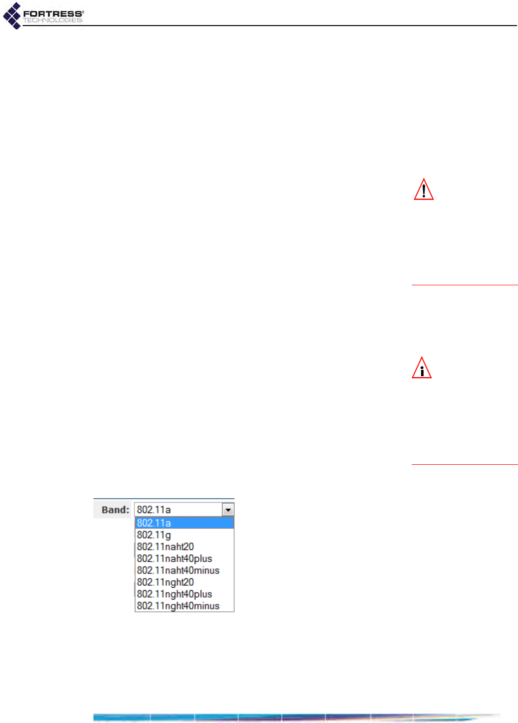
Bridge GUI Guide: Network Configuration
62
5 GHz and 2.4 GHz Options
Radios installed as Radio 1 in radio-equipped Fortress Bridges
(refer to Table 3.3, above) can operate in either the 5 GHz
802.11a frequency band or the 802.11g 2.4 GHz band of the
radio spectrum, according to your selection in the Band field.
By default, a dual-band radio installed as Radio 1 in a multi-
radio Bridge is configured to operate in the 2.4 GHz 802.11g
band. The single dual-band radio installed in the ES210 is
configured to operate in the 802.11a band by default.
CAUTION:
The
4.400–4.750 GHz
frequency range is regu-
lated by the U.S. Depart-
ment of Defense. Use of
military band radios is
strictly forbidden out-
side of U.S. military ap-
plications and authority.
In Bridges equipped with more than one radio, the additional
radio(s) can function in only a single frequency band: the
5 GHz 802.11a band in standard-equipment radios, or the
4.4 GHz military band in Bridges that support this option.
The radio Band setting is among those subject to the relevant
regulatory domain (Section 3.3.1.3). In some cases, in order to
bring the Bridge into compliance, dual-band radios could be
automatically fixed on the 802.11g band and radios fixed on the
802.11a band could be disabled altogether. Refer to Section
3.3.2 for more operational detail, and consult your local
regulatory authority for the applicable specifications and
requirements for radio devices and transmissions.
802.11n Options
NOTE: Although
fully compatible
with the IEEE standard,
Bridge 802.11n-capable
radios cannot perform
MIMO (Multiple-Input
Multiple-Output), or
spatial multiplexing, at
this time.
BSSs configured on the radio(s) installed in certain Bridge
models are additionally capable of 802.11n operation (refer to
Table 3.3 on page 57), as defined by this recent IEEE
amendment to the 802.11 standards.
The ES210 Bridge’s Station Mode function (refer to Section
3.3.5) does not support 802.11n operation. You must set the
ES210 radio’s Band to 802.11a or 802.11g before you can add a
Station Interface to the ES210 radio.
A Bridge radio BSS configured to use the 802.11n standard is
fully interoperable with other 802.11n network devices.
Figure 3.6. 802.11n-capable, dual-band radio
Band
options, ES210, ES440, ES820
Selecting an 802.11n option in a radio’s Band field permits the
Bridge to take advantage of radio enhancements and traffic
handling efficiencies defined in the newer standard, including
both 20 MHz and 40 MHz channel widths, frame aggregation

Bridge GUI Guide: Network Configuration
63
and block acknowledgement (block ACK), and smaller frame
headers and inter-frame gaps.
On 802.11n-capable radios, there are three possible high-
throughput (ht) 802.11n options for each frequency band
supported on the radio: three for the 5 GHz 802.11na band and
three for the 2.4 GHz 802.11ng band, when present:
ht20 - 802.11n - High-Throughput 20 MHz, the radio will use
only 20 MHz channel widths, while taking advantage of the
standard’s traffic handling efficiencies.
ht40plus - High-Throughput 40 MHz plus 20 MHz, the radio
can use 40 MHz channel widths by binding the selected
20 MHz channel to the adjacent 20 MHz channel above it
on the radio spectrum.
ht40minus - High-Throughput 40 MHz minus 20 MHz, the
radio can use 40 MHz channel widths by binding the
selected 20 MHz channel to the adjacent 20 MHz channel
below it on the radio spectrum.
3.3.2.3 Channel and Channel Width
The Channel setting selects the portion of the radio spectrum
the radio will to use to transmit and receive—in order to provide
wireless LAN access or to establish the initial connections in a
mesh network.
NOTE: Consult
your local regula-
tory authority for appli-
cable radio device and
transmission rules and
for DFS channel desig-
nations.
The channels available for user selection are determined by
the frequency band the radio uses, subject to the relevant
regulatory domain rules. In most regulatory domains, certain
channels in the 5 GHz frequency band are designated DFS
(Dynamic Frequency Selection) channels. DFS compliance
also restricts the channels available for user selection (and
broadcast) on 802.11a radios.
The Bridge GUI presents only currently permissible channels
for user selection, according to the currently specified Country
of operation (Section 3.3.1.3) and Band (Section 3.3.2.2),
excluding channels on the radio’s DFS Channel Exclusions list
(Section 3.3.3).
A dual-band radio that uses the 2.4 GHz 802.11g band by
default (Radio 1 in the multiple radio ES440, ES520 and ES820
Bridges) is set to channel 1 by default.
A second internal 5 GHz 802.11a radio (Radio 2 in non-military-
band ES440, ES520 and ES820) or a single dual-band radio
that uses 802.11a by default (Radio 1 in the ES210) has a
default channel setting of 149. In the military-band ES440,
Radio 2 is set to channel 4100 by default.
Whether they use the 5 GHz 802.11a band or the 4.4 GHz
military band, Radio 3 and Radio 4 in the ES440 are set by
default to unique channels.

Bridge GUI Guide: Network Configuration
64
Table 3.4 shows all channels available for selection on military
band Bridge radios, with their corresponding frequencies.
To the right of the Channel field, the Radio Settings screen
displays the view-only actual channel over which the radio is
communicating. If the actual channel is different from the user-
specified Channel, the actual channel was set by DFS
operation. Refer to Section 3.3.3 for more detail.
The Radio Settings screen also displays Channel Width
informationally, view-only.
3.3.2.4 Network Type
Whether the Bridge is a member of a multi-node, point-to-
multipoint (PtMP) network (the default) or a two-node, point-to-
point (PtP) network affects allowable TxPower settings for the
Bridge’s current country of operation (refer to Section 3.3.1.3).
You must enter the correct value for Network Type in order to
comply with the requirements of the applicable regulatory
domain.
You can configure Network Type only in Advanced View.
3.3.2.5 Antenna Gain
NOTE: Antenna
port labels corre-
sponds to radio num-
bering: Radio 1 uses
ANT1, and so on.
Measured in dBi (decibels over isotropic), Antenna Gain is used
to determine allowable TxPower settings for the Bridge’s
current country of operation (refer to Section 3.3.1.3). Consult
the documentation for the antenna connected to the radio you
are configuring to determine the antenna’s gain.
The gain of the antenna affects the distribution of the radio
frequency (RF) energy it emits and is therefore subject to the
requirements of the applicable regulatory domain. You must
enter the correct value for Antenna Gain in order to comply with
local regulations.
The dropdown provides selectable values from 0–50 dBi
(inclusive). The default antenna gain depends on the Bridge
you are configuring. In multi-radio Bridges, all radios have a
default antenna gain setting of 9 dBi. The ES210 radio’s default
antenna gain is 5 dBi.
You can configure Antenna Gain only in Advanced View.
Table 3.4. 4.4 GHz Military Band Radio Channels
Channel Frequency (GHz) Channel Frequency (GHz)
4100 4.476 4128 4.616
4104 4.496 4132 4.636
4108 4.516 4136 4.656
4112 4.536 4140 4.676
4116 4.556 4144 4.696
4120 4.576 4148 4.716
4124 4.596

Bridge GUI Guide: Network Configuration
65
WARNING: The
FCC (the Bridge’s
default regulatory do-
main) requires anten-
nas to be professionally
installed; the installer is
responsible for ensur-
ing compliance with
FCC limits, including
TX power restrictions.
3.3.2.6 Tx Power Mode and Tx Power Settings
The default transmit power level for all radios is Auto, which
directs the Bridge to automatically set the transmit power at the
maximum allowed for the selected Band, Channel, Network
Type and Antenna Gain (refer to sections 3.3.2.2 through
3.3.2.5) by the regulatory domain established in Country Code
(Section 3.3.1.3).
Alternatively, you can specify a transmit power level for the
radio. As for Auto power-level selection, the set of usable
values for TxPower is a function of the Bridge’s regulatory
domain, in combination with its Band, Channel, Network Type
and Antenna Gain settings for that radio.
The power at which radios are permitted to transmit is subject
to the applicable regulatory domain. You must configure the
Bridge with accurate values in order to comply with local
regulations. Consult your local regulatory authority for
applicable specifications and requirements for radio devices
and transmissions.
In environments with a dense distribution of APs (and resulting
potential for interference), it may be desirable to select a lower
Tx Power setting than the default (Auto) for a radio using the
802.11g band. The Auto setting is otherwise appropriate for all
radios.
You can configure TxPower only in Advanced View.
3.3.2.7 Distance
The Distance setting configures the maximum distance for
which a radio in a mesh network must adjust for the
propagation delay of its transmissions.
Distance is set in kilometers (the default) or miles, according to
the global Radio Units setting (Section 3.3.1.2), in increments of
1 and values from 1 to 56 km or 1 to 35 miles.
In a network deployment, the Distance setting on the networked
radios of all member Bridges should be the number of
kilometers (or miles) separating the two Bridges with the
greatest, unbridged distance between them. In Figure 3.7, the
Distance setting would be 3 kilometers: the longest distance in
the network between two Bridges without another Bridge
between them.
Propagation delay is not a concern at short range. At distances
of one (kilometer or mile) and under, you should leave the
setting at 1 (the default for both radios).
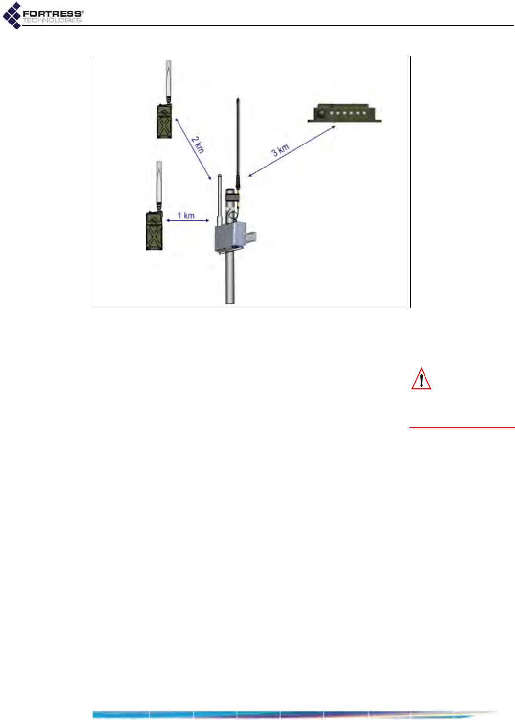
Bridge GUI Guide: Network Configuration
66
Figure 3.7. Bridge network deployment with radio Distance settings of 3 kilometers
You can configure Distance only in Advanced View.
3.3.2.8 Beacon Interval
CAUTION: Radios
using DFS chan-
nels (Section 3.3.3) must
use the default Beacon
Interval of 100 ms.
Bridge radios transmit beacons at regular intervals to
announce their presence on their network, the strength of their
RF signals and, when Advertise SSID is enabled (Section
3.3.4.2), the SSIDs of their basic service sets (BSSs). The
beacon interval is also used to count down the DTIM (Delivery
Traffic Indication Message) period (refer to Section 3.3.4.8).
In mesh network deployments, all of the Bridges in the network
must use the same Beacon Interval.
You can configure the number of milliseconds between
beacons in whole numbers between 25 and 1000. You cannot
disable the beacon. The default Beacon Interval is 100
milliseconds, which is optimal for almost all network
deployments and recommended for bridging operation.
A longer beacon interval conserves power and leaves more
bandwidth free for data transmission, potentially improving
throughput. A shorter interval provides faster, more reliable
passive scanning for network nodes and devices, potentially
improving mobility.
Fortress recommends retaining the Beacon Interval default
unless operating conditions require a change.
You can configure Beacon Interval only in Advanced View.

Bridge GUI Guide: Network Configuration
67
3.3.2.9 Short Preamble
The short preamble is used by virtually all wireless devices
currently being produced. The Short Preamble is therefore the
most likely requirement for new network implementations and
is Enabled by default. The setting applies only to 802.11g band
operation; it is greyed out for Radio 2 and for Radio 1 when it is
configured to use the 802.11a band.
When Short Preamble is Disabled connecting devices must use
the long preamble, which is still in use by some older 802.11b
devices. If the WLAN must support devices that use the long
preamble, you must set Short Preamble for the radio on which
the access point BSS is configured to Disabled.
You can configure Short Preamble only in Advanced View.
3.3.2.10 Noise Immunity
For radios using the 802.11a band (Section 3.3.2.2), enabling
Noise Immunity allows the radio to aggressively lower the
receive threshold for the signal strength of connected nodes, in
order to compensate for unusual levels of local interference.
Noise Immunity is Disabled by default, and Fortress
recommends retaining the default, unless operating conditions
require a change.
3.3.2.11 Configuring Individual Radio Settings:
Table 3.5 shows which Radio Settings appear in the two GUI
views.
1Log on to the Bridge GUI through an Administrator-level
account and select Configure -> Radio Settings from the
menu on the left.
2If you are configuring one or more Advanced View settings
(see Table 3.5), click ADVANCED VIEW in the upper right
corner of the page. (If not, skip this step.)
3In the Radio Settings screen’s Radio Settings frame, enter
new values for those settings you want to configure
(described in sections 3.3.2.1 through 3.3.2.10, above).
Table 3.5. Radio Settings
Simple & Advanced Views Advanced View Only
Admin. State Network Type
Band Beacon Interval
Channel Distance
Noise Immunity Antenna Gain
TxPower
Short Preamble
Channel Exclusions
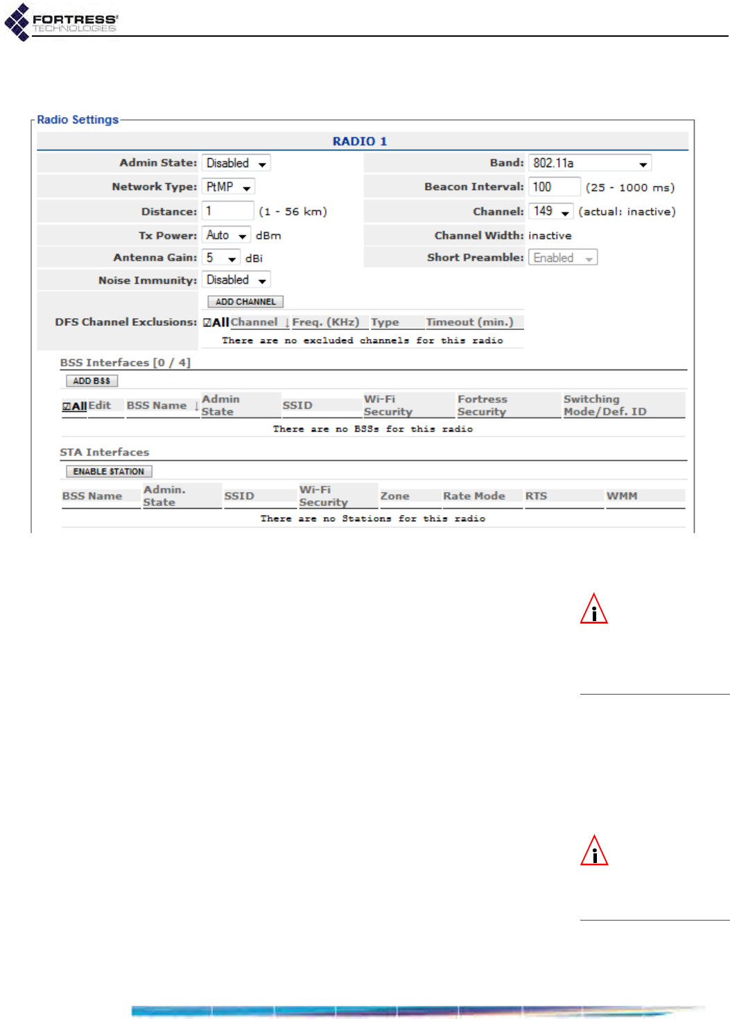
Bridge GUI Guide: Network Configuration
68
4Click APPLY in the upper right of the screen (or RESET
screen settings to cancel your changes).
Figure 3.8. Advanced View
RADIO 1 Radio Settings
frame, all radio-equipped platforms
3.3.3 DFS Operation and Channel Exclusion
NOTE:
The
Bridge’s regulato-
ry domain is deter-
mined by the specified
Country
of operation, de-
scribed in Section 3.3.1.3.
Most regulatory domains, including the Bridge’s default FCC
domain, require that certain channels in the 5 GHz 801.11a
frequency band operate as DFS (Dynamic Frequency
Selection) channels.
DFS is a radar (radio detection and ranging) avoidance
protocol. Devices transmitting on a DFS channel must detect
approaching radar on the channel, vacate the channel within
10 seconds of doing so, and stay off the channel for a minimum
of 30 minutes thereafter.
Radios using the 2.4 GHz 802.11g frequency band or the
4.4 GHz military band are not subject to DFS.
3.3.3.1 DFS Operation on the Bridge
NOTE: Consult
your local regula-
tory authority for appli-
cable DFS channel
designations.
Bridge radios deployed in a mesh network must use a common
channel in order to remain connected. For radios on which a
Bridging-enabled BSSs are configured (Section 3.3.4), the
actual channel on which the network transmits and receives will
be subject to change according to the Bridge’s DFS
implementation.
In order to keep all network nodes connected, a network Bridge
forced by DFS to change the channel on a bridging radio will
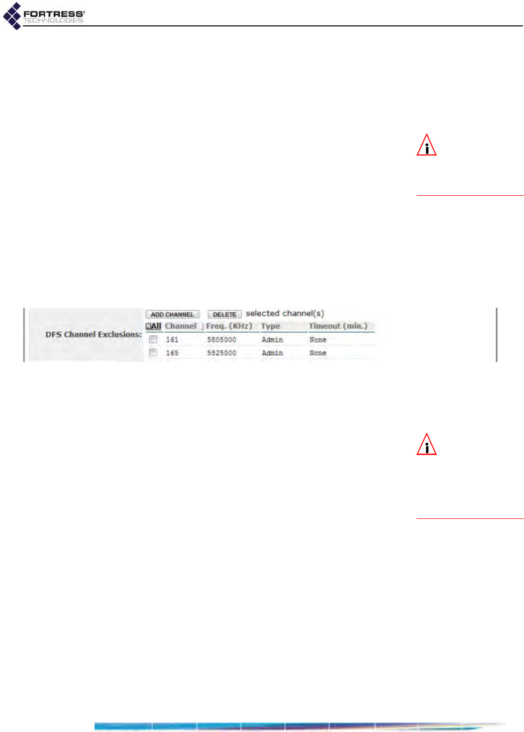
Bridge GUI Guide: Network Configuration
69
signal the impending change and transmit the new channel
number to the network, before switching its bridging radio to
the new channel. Bridges receiving this transmission will do the
same, until the new channel has been propagated to every
Bridge in the network and all are all connected over the new
channel.
NOTE: Radios us-
ing DFS channels
must use the default
Beacon Interval of 100
ms (Section 3.3.2.8).
If you manually change the Channel setting on a bridging radio
(Section 3.3.2.3), the new channel will be propagated to the
rest of the network in the same manner.
You can observe the view-only actual channel on Configure ->
Radio Settings, to the right of the Channel setting (which persists
as specified as the actual channel changes).
3.3.3.2 Channel Exclusion
For each enabled radio, Fortress Bridges maintain a list of
channels excluded from that radio’s use, Channels that are
unavailable for DFS or for manual selection. Bridging radios in
a mesh network maintain a global list of excluded channels by
propagating their channel exclusions to all nodes.
Figure 3.9. Advanced View
DFS Channel Exclusions
list, all radio-equipped platforms
Channels can be excluded in four ways:
The channel was manually added to the radio’s excluded
list (see below).
NOTE: While there
can be no radar
events on 4.4 GHz mili-
tary band radio, it can
receive a remote chan-
nel change from a net-
work peer.
For DFS channels, a radio using the channel detected
radar and had to change to a different channel. The
channel on which radar was detected is excluded from use
for 30 minutes, after which it will automatically become
available again.
For bridging radios, the channel was learned remotely from
another node in the network. Remotely learned channel
exclusions will age out a radio’s excluded list if the remote
Bridge stops propagating the exclusion (or drops out of the
network).
For multi-radio Bridges, the channel is in use by the other
radio internal to the Bridge and so is excluded from use by
the current radio.
You may want to exclude a channel from use if you are
experiencing abnormal interference on the channel, for
example, or in order to avoid a channel on which intermittent
radar is known to take place.
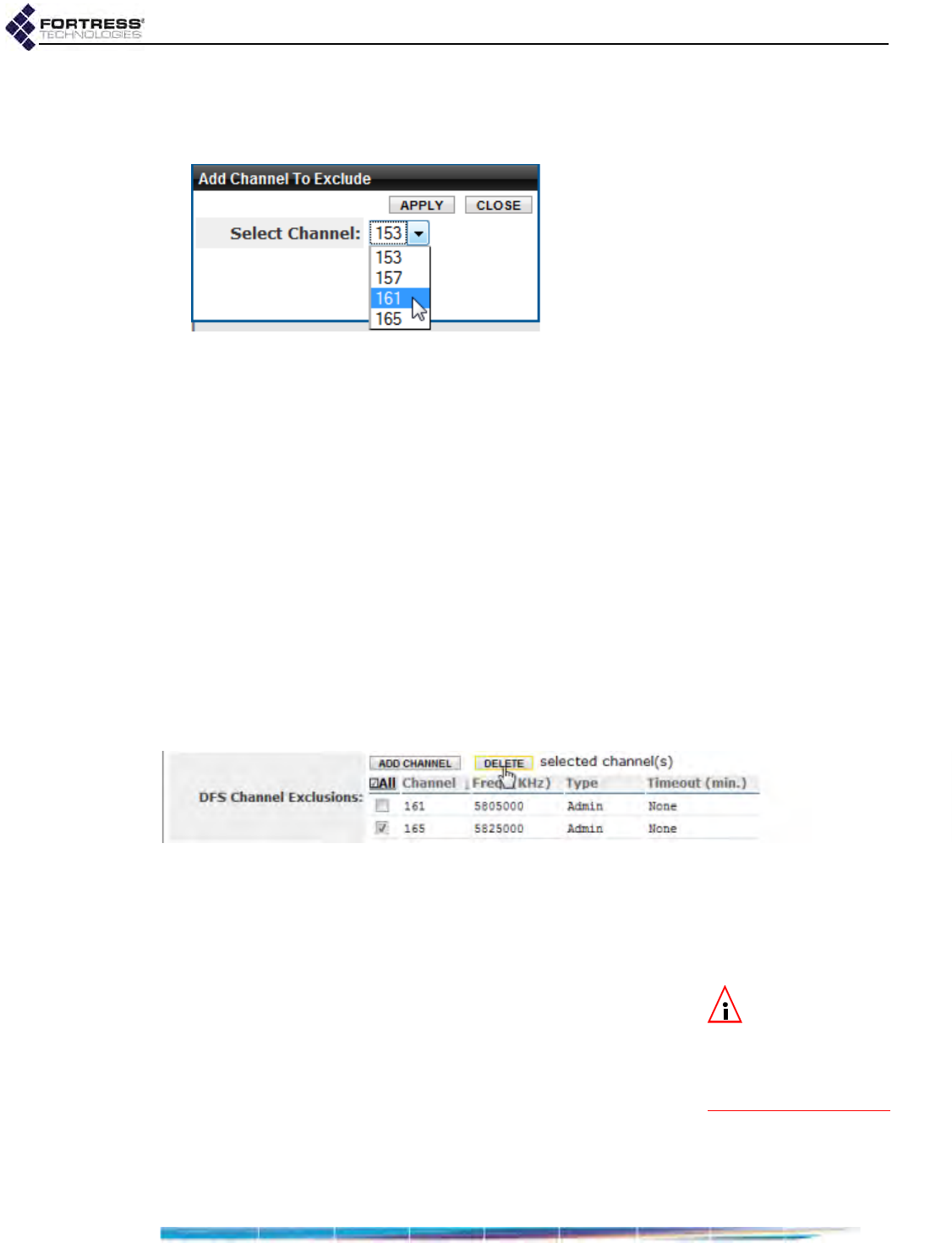
Bridge GUI Guide: Network Configuration
70
You can observe the channels currently excluded from each
radio’s use, in Advanced View only, on the Channel Exclusions
list on Configure -> Radio Settings.
Figure 3.10. Advanced View
Add Channel To Exclude
dialog, all radio-equipped platforms
To manually add channels for exclusion:
1Log on to the Bridge GUI through an Administrator-level
account and select ADVANCED VIEW in the upper right corner
of the page, then Configure -> Radio Settings from the menu
on the left.
2In the Radio Settings screen’s Radio Settings frame, above
the Channel Exclusions list, click ADD CHANNEL.
3In the Add Channel to Exclude dialog, choose a channel
from the Select Channel dropdown and click APPLY (or
CLOSE the dialog without adding the channel).
Delete a channel from the exclusion list by clicking to place a
check in the box to the left of its entry on Channel Exclusions
and then clicking DELETE at the top of the frame. Delete all
channels by clicking All to check all their boxes and then
DELETE.
Figure 3.11. deleting a channel exclusion, all radio-equipped platforms
You must be in Advanced View to access the Channel
Exclusions list.
3.3.4 Radio BSS Settings
NOTE:
An ES210
Bridge can alterna-
tively support a single
wireless client
STA
in-
terface. Refer to Section
3.3.5.
A Bridge radio can support up to four Basis Service Sets
(BSSs), each with its own SSID and associated settings and
serving as an independent, virtual interface.
In a Fortress FastPath Mesh network, a given BSS can either
provide mesh connections to other Fortress Bridge Mesh
Points or connect other wireless devices (Non-Mesh Points) to
the FastPath Mesh. Refer to Section 3.2.1 for more detail.
In a mesh network under STP link management, a given BSS
can either provide mesh network connections to other Fortress
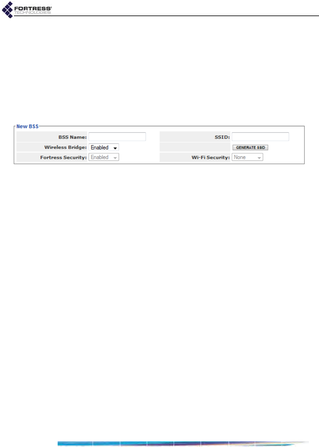
Bridge GUI Guide: Network Configuration
71
Bridges or serve as a WLAN access point (AP). Refer to
Section 3.2.2 for more detail.
You can view the BSSs configured for each radio, under the
radio’s entry on Configure -> Radio Settings.
No BSSs are configured on Bridge radios by default. To create
a BSS you need only specify a unique name (Section 3.3.4.1)
and SSID (Section 3.3.4.2).
Sections 3.3.4.1 through 3.3.4.14 describe complete settings to
configure Bridge radio BSSs; step-by-step instructions for
changing them follow these sections.
Figure 3.12. Simple View
New BSS
settings frame, all radio-equipped platforms
3.3.4.1 BSS Administrative State and Name
Admin State simply determines whether the BSS is Disabled or
Enabled. Newly created BSSs are Enabled by default.
You can enable and disable radio BSSs only in Advanced View.
You must specify a BSS Name, an alphanumeric identifier of up
to 254 characters and unique to the current radio, in order to
create a BSS.
3.3.4.2 BSS SSID and Advertise SSID
You must specify a service set identifier in order to create a
BSS. You can manually enter an SSID of up to 32
alphanumeric characters, or randomly generate a 16-digit
ASCII string to use for the SSID.
The SSID associated with each BSS is a unique string of up to
32 characters normally included in the beacon and probe-
response 802.11 management frames transmitted by access
points (APs) and wireless bridges.
When they are broadcast (the default), SSIDs are used to
advertise which devices can connect to the wireless network.
When Advertise SSID is Disabled (see below), SSIDs function
more like device passwords, limiting network access to those
devices that “know” the BSSs unadvertised SSID. (Disabling
Advertise SSID is not, however, sufficient to secure the BSS.)
When Advertise SSID is Disabled, the SSID string is deleted
from the radio beacons. A setting of Enabled, the default,
causes the SSID to be included in these packets.
You can set a BSS’s SSID in either Bridge GUI view. You can
enable/disable Advertise SSID only in Advanced View.

Bridge GUI Guide: Network Configuration
72
3.3.4.3 Wireless Bridge and Minimum RSS
NOTE: When Fast-
Path Mesh is en-
abled, your selection in
Wireless Bridge automati-
cally configures the in-
terface’s FP Mesh Mode
(described below).
In a Fortress FastPath Mesh network, the Wireless Bridge
setting, in conjunction with FastPath Mesh Mode (below),
determines whether the BSS will provide network connections
to other Fortress Bridge Mesh Points (Enabled) or connect
other Non-Mesh Points to the FastPath Mesh (Disabled).
FastPath Mesh bridging is described in Section 3.2.1.
In a mesh network under STP link management, the Wireless
Bridge setting determines whether the BSS will act as a
wireless bridge (Enabled) or a conventional WLAN access point
(Disabled). STP bridging is described in Section 3.2.2.
NOTE: Enabling
Wireless Bridge for
the BSS enforces a For-
tress Security setting of
Enabled (Section
3.3.4.13).
On the single-radio ES210, Wireless Bridge is Enabled by
default for BSSs, when the radio is left on the default 5 GHz
802.11a band.
On Bridges with two radios, the ES520 and ES820, Wireless
Bridge is Disabled by default for BSSs on Radio1, when it is left
on the default 2.4 GHz 802.11g band, and Enabled by default
for BSSs on Radio 2.
On the four-radio ES440, Wireless Bridge is also Disabled by
default for BSSs on Radio1, when it is left on the default 2.4
GHz 802.11g band, and Enabled by default for BSSs on Radio
2, Radio 3 and Radio 4.
Once a Wireless Bridge value has been established for a BSS,
the setting cannot be reconfigured. You must delete the BSS
and recreate it with the new Wireless Bridge value in order to
make such a change.
When Wireless Bridge is Enabled, you can also configure the
minimum received signal strength that the other nodes
(bridging-enabled Bridges) in range must maintain in order to
remain connected to the current Bridge.
Minimum signal strength received (Minimum RSS) is configured
in whole dBm (decibels referenced to milliwatts) from -95 to
0 dBm. The default is -80 dBm.
You can enable/disable Wireless Bridge in either Bridge GUI
view. You can set the Minimum RSS only in Advanced View.
3.3.4.4 User Cost Offset and FastPath Mesh Mode
When FastPath Mesh is enabled, User Cost Offset allows you
to weight the interface more or less heavily in the FP Mesh cost
equation in order to make it less attractive than other
interfaces.
Enter a non-negative integer between 0 (zero) and
4,294,967,295. The higher the offset, the less attractive the
interface. A neighbor with the maximum cost (4,294,967,295)
will never be used to route traffic. The default is 0 (zero).
Network Cost Weighting and the FP Mesh cost equation are
described in Section 3.2.1.5.

Bridge GUI Guide: Network Configuration
73
Because of its dependency on the BSSs Wireless Bridge
function, the FastPath Mesh Mode of a wireless interface on
the Bridge is not among the user controls provided.
When FastPath Mesh is enabled and the BSS is configured as
bridging interface (Wireless Bridge: Enabled), the BSS is
automatically configured as an FP Mesh Core interface,
allowing it to connect to other FP Mesh-enabled Fortress Mesh
Points (MPs).
When FastPath Mesh is enabled and the BSS is configured as
a network Access interface (Wireless Bridge: Disabled), the BSS
is automatically configured as an FP Mesh Access interface,
allowing it to connect to connect Non-Mesh Points (NMPs) to
the FP Mesh network.
FastPath Mesh bridging is described in Section 3.2.1.
3.3.4.5 BSS Switching Mode and Default VLAN ID
Two settings configure the BSS’s VLAN handling:
Default VLAN ID - associates the BSS with a specified
VLAN ID. The Bridge supports VLAN IDs 1–4094. If the
VLAN ID you enter is not already present on the VLAN
Active ID Table (Section 3.9.3), it will be added. The default
is 1.
Switching Mode - establishes the BSS’s behavior with
regard to data packet VLAN tagging:
Access - (the default) configures the interface to accept
only: (1) packets that do not contain VLAN tags and
(2) specialized priority-tagged packets, which provide
support for Ethernet QoS exclusive of VLAN
implementations.
NOTE: There is
only one VLAN
trunk per Bridge, used
by all Trunk ports. It is
defined by the Bridge’s
VLAN Active ID Table
(Section 3.9.3).
Trunk - configures the interface to accept incoming
packets with any VLAN tag in the VLAN ID table and to
pass packets with their VLAN tagging information
unchanged, including 802.1p priority tags.
Refer to Section 3.9 and to Table 3.14 for a complete
description of VLAN handling on the Bridge.
To support QoS, the Bridge treats incoming priority-tagged
packets (characterized by a VLAN ID of zero) as untagged
packets, but marks them for sorting into QoS priority queues
according to the user-priority value contained in their VLAN
tags. (Refer to Section 3.8 for details on the Bridge’s QoS
implementation).
You can configure BSS VLAN settings only in Advanced View.
3.3.4.6 BSS G Band Only Setting
The G Band Only setting applies only to BSSs on radios using
the 2.4 GHz frequency band (refer to Section 3.3.2.2). The

Bridge GUI Guide: Network Configuration
74
function is Disabled by default, at which setting the BSS
accepts connections from both 802.11g and 802.11b devices.
Enabling G Band Only prevents 802.11b wireless devices from
connecting to the BSSs. The older 802.11b is the slower of the
two 2.4 GHz wireless standards and most new devices support
802.11g. Consult the connecting device’s documentation to
determine which standard(s) it supports.
The G Band Only setting does not apply to BSSs on 802.11a
radios.
You can configure G Band Only only in Advanced View.
3.3.4.7 BSS WMM Setting
NOTE:
On BSSs
serving as Core in-
terfaces in a FP Mesh
network (Section 3.3.4.4),
Fortress recommends
the WMM default of
En-
abled
, to allow prioriti-
zation of FP Mesh
control packets.
Traffic received on BSSs Enabled for Wi-Fi Multimedia (the
default) is prioritized according to the QoS (Quality of Service)
tags included in its VLAN tags, if present, or directly in its
802.11 headers, if no VLAN tags are present.
Disabling WMM disables only the priority treatment of packets
received wirelessly, disregarding any priority marking in the
802.11 header. When WMM is disabled on a BSS, traffic
received on the interface is treated as untagged and marked
internally for Medium (or Best Effort) QoS handling. The internal
marking is used if the data is transmitted out an interface that
requires marking (such as another WMM-enabled BSS or an
802.1Q VLAN trunk).
Refer to Section 3.8 for more on the Bridge’s WMM and QoS
implementation.
3.3.4.8 BSS DTIM Period
APs buffer broadcast and multicast messages for devices on
the network and then send a Delivery Traffic Indication
Message to “wake-up” any inactive devices and inform all
network clients that the buffered messages will be sent after a
specified number of beacons have been transmitted. (The
beacon interval, described in Section 3.3.2.8, is configured on
the Radio Settings screen.)
The DTIM Period determines the number of beacons in the
countdown between transmitting the initial DTIM and sending
the buffered messages. Whole values from 1 to 255, inclusive,
are accepted; the default is 1.
A longer DTIM Period conserves power by permitting longer
periods of inactivity for power-saving devices, but it also delays
the delivery of broadcast and multicast messages. Too long a
delay can cause multicast packets to go undelivered.
Because the broadcast beacon counts down the DTIM Period,
the specified Beacon Interval (configured on the Radio Settings
screen and described in Section 3.3.2.8.) also affects the DTIM
function.
You can configure DTIM Period only in Advanced View.

Bridge GUI Guide: Network Configuration
75
3.3.4.9 BSS RTS and Fragmentation Thresholds
The RTS Threshold allows you to configure the maximum size
of the frames the BSS sends without using the RTS/CTS
protocol. Frame sizes over the specified threshold cause the
BSS to first send a Request to Send message and then receive
a Clear to Send message from the destination device before
transmitting the frame.
The RTS Threshold is measured in bytes. A value of zero (0)
disables the function (the default), or whole values between 1
and 2345 are accepted.
The smaller the RTS Threshold, the more RTS/CTS traffic is
generated at the expense of data throughput. On large busy
networks, however, RTS/CTS speeds recovery from radio
interference and transmission collisions, and a relatively small
RTS Threshold may be necessary to achieve significant
improvements.
The Frag. Threshold allows you to configure the maximum size
of the frames the BSS sends whole. Frame sizes larger than
the specified threshold are broken into smaller frames before
they are transmitted. An acknowledgement is sent for each
frame received, and if no acknowledgement is sent the frame is
retransmitted.
The Frag. Threshold is measured in bytes. A value of zero (0)
disables the function (the default), or whole values between
256 and 2345 are accepted.
Fragmentation becomes an advantage in networks that are:
experiencing collision rates higher than five percent
subject to heavy interference or multipath distortion
serving highly mobile network devices
A relatively small fragmentation threshold results in smaller,
more numerous frames. Smaller frames reduce collisions and
make for more reliable transmissions, but they also use more
bandwidth. A larger fragmentation threshold results in fewer
frames being transmitted and acknowledged and so can
provide for faster throughput, but larger frames can also
decrease the reliability with which transmissions are received.
You can configure RTS and fragmentation thresholds only in
Advanced View.
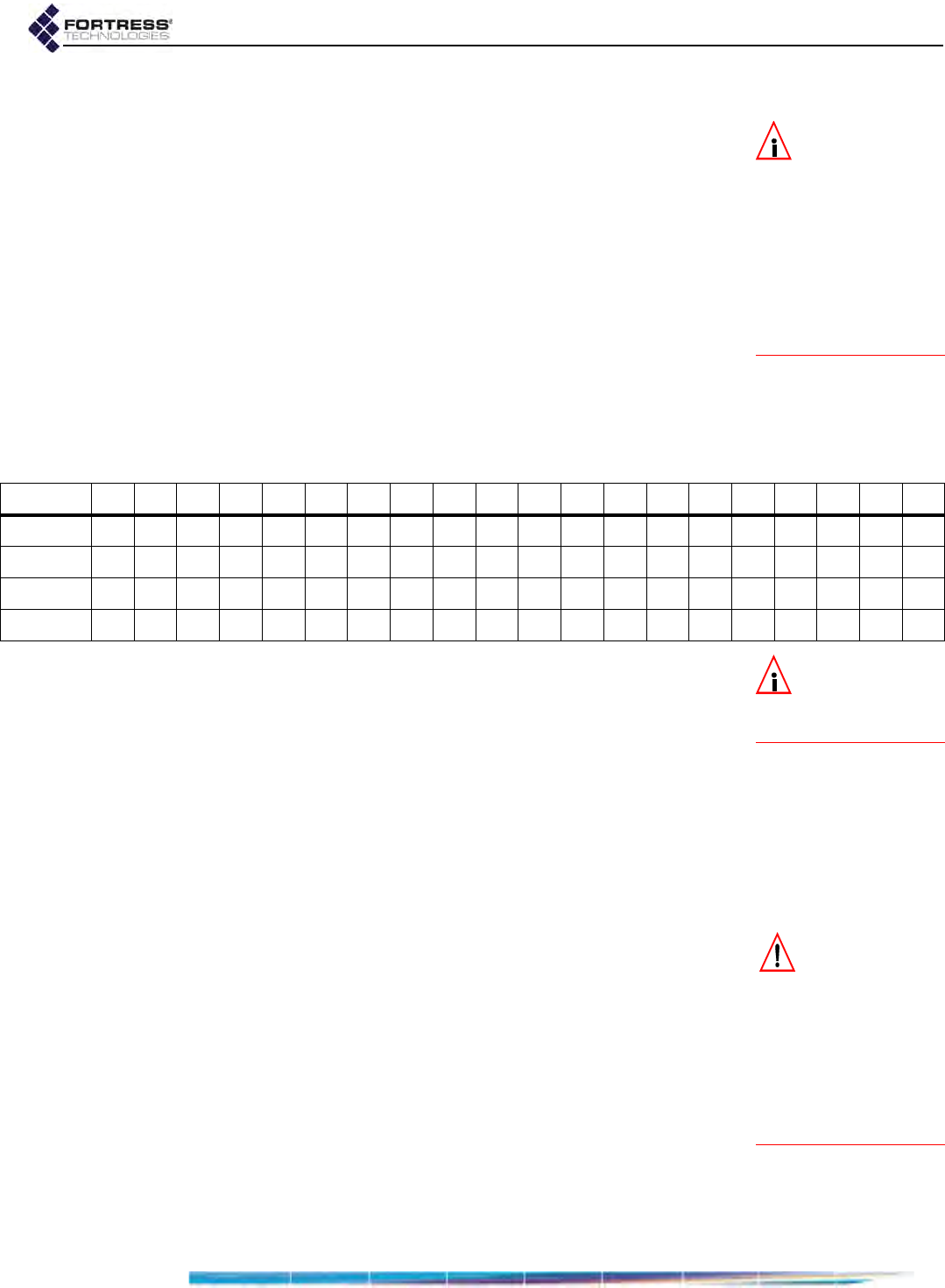
Bridge GUI Guide: Network Configuration
76
3.3.4.10 BSS Unicast Rate Mode and Maximum Rate
NOTE: You can
configure the uni-
cast minimum rate in
the Bridge CLI (refer to
the CLI Software
Guide). On a radio us-
ing any 802.11g band,
the default is 1 Mbps.
On a radio using any
802.11a band, the de-
fault is 6 Mbps.
When a BSS is configured to use a Unicast Rate Mode setting
of auto (the default), the interface dynamically adjusts the bit
rate at which it transmits unicast data frames—throttling
between the configured Unicast Maximum Rate and the
minimum rate—to provide the optimal data rate for the
connection.
At a Unicast Rate Mode setting of fixed, the BSS will use the
configured Unicast Maximum Rate for all unicast transmissions.
Transmission rates are set in megabits per second (Mbps).
Unicast Maximum Rate can be set only to a value greater than
or equal to the minimum rate. Usable values for Unicast
Maximum Rate settings depend on the Band setting for the
radio on which the BSS is configured, as indicated by the
markers in Table 3.6.
NOTE: Radio Band
settings are cov-
ered in detail in Section
3.3.2.2).
The default Unicast Maximum Rate for a new BSS specifies the
highest setting possible, as determined by the 802.11 standard
in use by the radio on which you are configuring the BSS. The
default depends on whether or not the radio is using 802.11n:
On a radio with an 802.11a or 802.11g Band setting, the default
Unicast Maximum Rate is 54 Mbps. On a radio using any of the
802.11n settings in either frequency band, the default Unicast
Maximum Rate is 65 Mbps.
You can configure Unicast Rate Mode and Unicast Maximum
Rate only in Advanced View.
3.3.4.11 BSS Multicast Rate
CAUTION: Too high
a Multicast Rate will
limit the ability of a Fast-
Path Mesh network to es-
tablish adjacency with
neighbor MPs unable to
receive multi-/broadcast
packets at the specified
rate (due to distance, for
example).
The bit rate at which a wireless interface sends multicast
frames is negotiated per connection. Multicast Rate sets a floor
for multicast transmissions by specifying the lowest bit rate at
which the BSS will send multicast frames.
BSSs on a radio configured by default to use the 2.4 GHz
802.11g band have a default Multicast Rate of 1 Mbps, which is
appropriate for a BSS using the 2.4 GHz frequency band,
typically to provide wireless access to local devices. Fortress
recommends leaving BSSs in the 802.11g band, including all
802.11ng options, at the default of 1.
BSSs on a radio fixed on, or configured by default to use, the
5 GHz 802.11a band have a default Multicast Rate of 6 Mbps,
Table 3.6. Usable BSS Rate Settings (in Mbps) per Radio Band Setting
1 2 5.5 6 9 11 12 18 24 36 48 54 6.5 13 19.5 26 39 52 58.5 65
802.11a
802.11g
802.11naht
802.11nght

Bridge GUI Guide: Network Configuration
77
which is appropriate for a BSS using the 5 GHz frequency
band, typically for network bridging. Fortress recommends
leaving BSSs in the 802.11a band, including all 802.11na
options, at the default of 6.
If the BSS will provide mesh network bridging in the 5 GHz
802.11a band, Fortress recommends a Multicast Rate of
6Mbps. Set a higher rate only if you are certain that all neighbor
links to the BSS can consistently maintain a significantly better
data rate than the new Multicast Rate.
3.3.4.12 BSS Description
You can optionally provide a Description of the BSS of up to
100 characters.
A BSS’s description displays only on the Advanced View Edit
BSS frame (Advanced View -> Configure -> Radio Settings ->
[BSS Interfaces] EDIT).
You can enter a Description for a BSS only in Advanced View.
3.3.4.13 BSS Fortress Security Setting
Traffic on BSSs Enabled for Fortress Security is subject to
Fortress’s Mobile Security Protocol (MSP), as configured on
the Bridge itself (refer to Section 4.1).
Fortress Security is Enabled on BSSs by default. When a BSS’s
Wireless Bridge setting is Enabled (refer to Section 3.3.4.3), its
Fortress Security setting is automatically fixed on Enabled and
the Fortress Security field is view-only.
Disabling Fortress Security on a BSS exempts all traffic on that
BSS from Fortress’s Mobile Security Protocol (MSP).
Standard Wi-Fi security protocols can be applied to the traffic
on a BSS (Section 3.3.4.14, below), regardless of whether the
BSS is Enabled or Disabled for Fortress Security.
3.3.4.14 BSS Wi-Fi Security Settings
As an alternative or in addition to Fortress Security, a number of
well known security protocols can be applied to the BSSs
created on the Bridge.
Your selection in the Wi-Fi Security field of the Edit BSS frame
determines the additional fields you must configure for that
setting—presented dynamically by the Bridge GUI for each
possible Wi-Fi Security selection.
Wi-Fi Security: None
If Fortress Security is disabled on a BSS and it has a Wi-Fi
Security setting of None, traffic on that BSS is unsecured.
CAUTION: An un-
secured wireless
interface leaves the net-
work unsecured.
Devices connected to an unsecured BSS send and receive all
traffic in the clear.
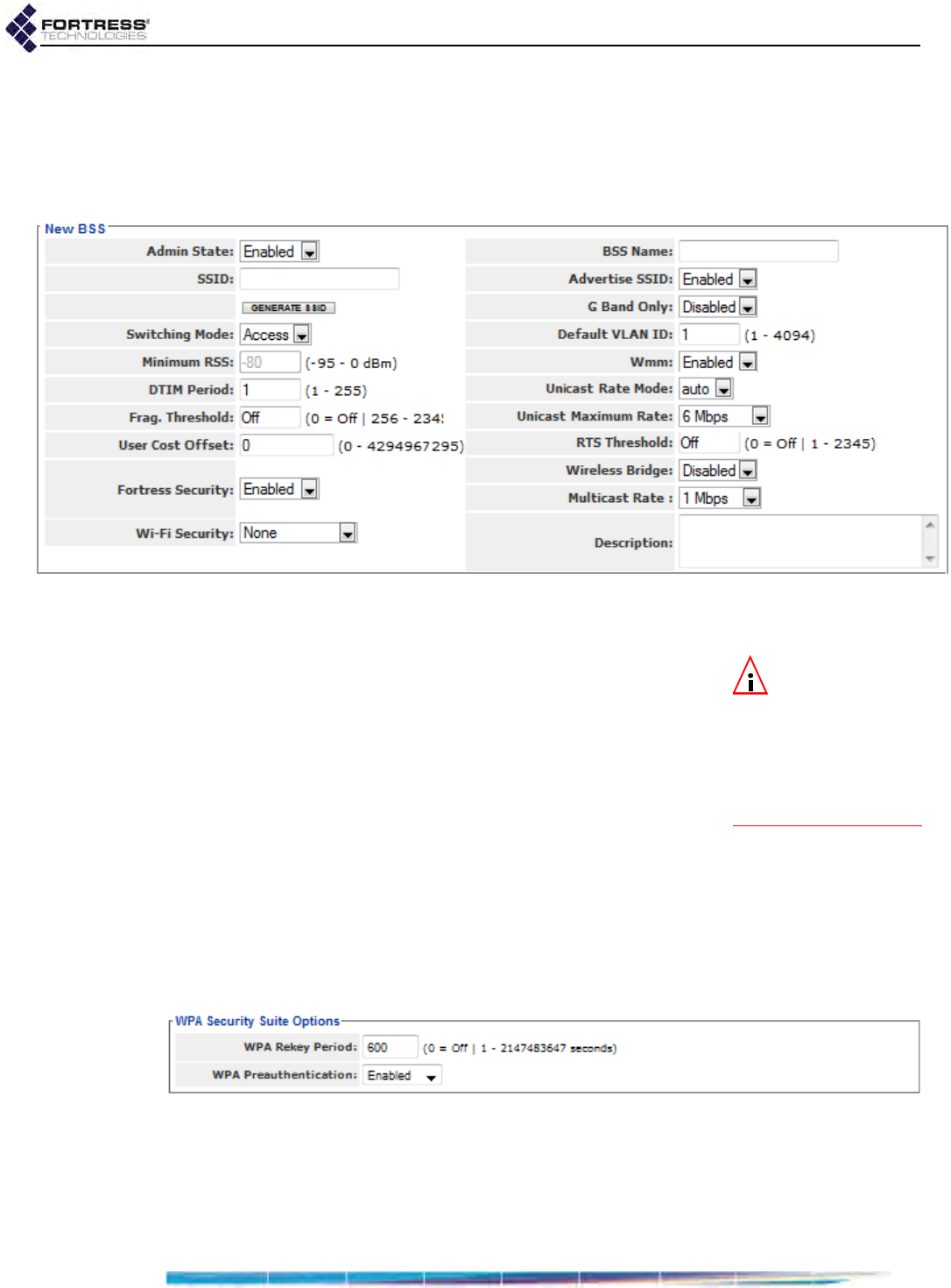
Bridge GUI Guide: Network Configuration
78
BSSs enabled for bridging (Section 3.3.4.3) must be Enabled
for Fortress Security. You cannot apply Wi-Fi Security to
bridging-enabled BSSs.
A Wi-Fi Security setting of None requires no further
configuration.
Figure 3.13. Advanced View
New BSS
settings frame, all radio-equipped platforms
WPA, WPA2 and WPA2-Mixed Security
NOTE: Enterprise
WPA and WPA2
modes require an 802.1X
authentication service to
be available, as part of
the Bridge configuration
(Section 4.3.2.7) or exter-
nally (Section 4.3.1).
WPA (Wi-Fi Protected Access) and WPA2 are the enterprise
modes of WPA (as distinguished from the pre-shared key
modes described below). You can specify that WPA or WPA2 be
used exclusively by the BSS, or you can configure it to be able
to use either by selecting WPA2-Mixed.
WPA and WPA2 use EAP-TLS (Extensible Authentication
Protocol-Transport Layer Security) to authenticate network
connections via X.509 digital certificates. In order for the Bridge
to successfully negotiate a WPA/WPA2 transaction, you must
have specified a locally stored key pair and certificate for the
Bridge to use to authenticate the connecting device as an EAP-
TLS peer, and at least one CA (Certificate Authority) certificate
must be present in the local certificate store. Refer to Section
6.2.1 for guidance on configuring an EAP-TLS key pair and
digital certificate.
Figure 3.14.
WPA Security Suite Options
frame for WPA2 enterprise modes, all radio-equipped platforms
You can configure WPA2 security in either Bridge GUI view.
WPA and WPA2-Mixed security are available for selection only
in Advanced View.
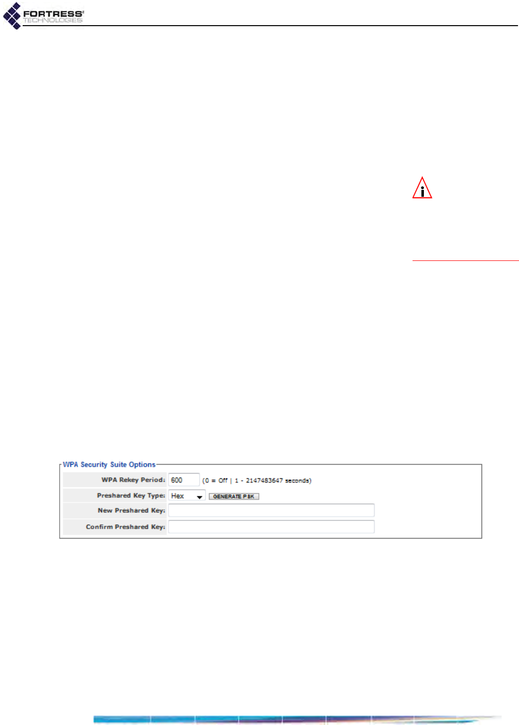
Bridge GUI Guide: Network Configuration
79
On the New/Edit BSS screens, these additional settings apply
to WPA, WPA2 and WPA2-Mixed selections:
WPA Rekey Period - specifies the interval at which new pair-
wise transient keys (PTKs) are negotiated or 0 (zero),
which disables the rekeying function: the interface will use
the same key for the duration of each session seconds.
Specify a new interval in whole seconds between 0 and
2147483647, inclusive. No WPA Rekey Period is specified
by default.
NOTE: WPA Preau-
thentication applies
only to wpa2 and wpa2
mixed enterprise mode
Wi-Fi Security settings. It
is not present when wpa
is selected
.
WPA Preauthentication - to facilitate roaming between
network access points, enabling WPA Preauthentication on
the BSS permits approaching WPA2 wireless clients to
authenticate on the Bridge while still connected to another
network access point, while wireless clients moving away
from the Bridge can remain connected while they
authenticate on the next network AP. WPA Preauthentication
is Disabled by default.
WPA-PSK, WPA2-PSK and WPA2-Mixed-PSK Security
WPA-PSK (Wi-Fi Protected Access) and WPA2-PSK are the
pre-shared key modes of WPA (as distinguished from the
enterprise modes described above). You can specify that WPA-
PSK or WPA2-PSK be used exclusively by the BSS, or you can
configure it to be able to use either by selecting WPA2-Mixed-
PSK.
Pre-shared key mode differs from enterprise mode in that PSK
bases initial key generation on a user-specified key or
passphrase instead of through digital certificates. Like
enterprise-mode, PSK mode generates encryption keys
dynamically and exchange keys automatically with connected
devices at user-specified intervals.
Figure 3.15.
WPA Security Suite Options
frame for WPA PSK modes, all radio-equipped platforms
On the New/Edit BSS screens, these additional settings apply
to WPA-PSK, WPA2-PSK and WPA2-Mixed-PSK selections:
WPA Rekey Period - specifies the interval at which new
keys are negotiated. Specify a new interval in whole
seconds between 1 and 2147483647, inclusive, or 0 (zero)
to permit the same key to be used for the duration of the
session.
Preshared Key Type - determines whether the specified key
is an ASCII passphrase or a Hexadecimal key.

Bridge GUI Guide: Network Configuration
80
New Preshared Key and Confirm Preshared Key - specify the
preshared key itself, as:
a plaintext passphrase between 8 and 63 characters in
length, when ASCII is selected for Preshared Key Type,
above.
a 64-digit hexadecimal string, when Hex is selected for
Preshared Key Type, above.
You can configure WPA2-PSK security in either Bridge GUI view.
WPA-PSK and WPA2-Mixed-PSK security are available for
selection only in Advanced View.
3.3.4.15 Configuring a Radio BSS
Table 3.7 shows which New/Edit BSS settings appear in the two
GUI views.
NOTE:
On the
ES210 Bridge, the
ADD
BSS
button is only
present when the
Station
Mode
function is dis-
abled (the default; refer
to Section 3.3.5.13).
1Log on to the Bridge GUI through an Administrator-level
account and select Configure -> Radio Settings from the
menu on the left.
2If you are configuring one or more Advanced View settings
(see Table 3.7), click ADVANCED VIEW in the upper right
corner of the page. (If not, skip this step.)
3In the Radio Settings screen’s Radio Settings frame:
If you are creating a new BSS, click the ADD BSS button
for the radio to which you want to add the BSS.
or
If you are reconfiguring an existing BSS, click the EDIT
button for the BSS you want to change.
Table 3.7. BSS Settings
Simple & Advanced Views Advanced View Only
BSS Name Admin State
SSID Advertise SSID
Wireless Bridge G Band Only
Fortress Security Switching Mode
Wi-Fi Security: partiala
a. The complete set of Wi-Fi options (Section 3.3.4.14) is avail-
able for selection only in Advanced View. Simple View provides
access to only None, WPA2 and WPA2-PSK options.
Default VLAN ID
Minimum RSS
WMM
DTIM Period
RTS Threshold
Frag. Threshold
Unicast Rate Mode
Unicast Maximum Rate
Multicast Rate
Description
Wi-Fi Security: complete
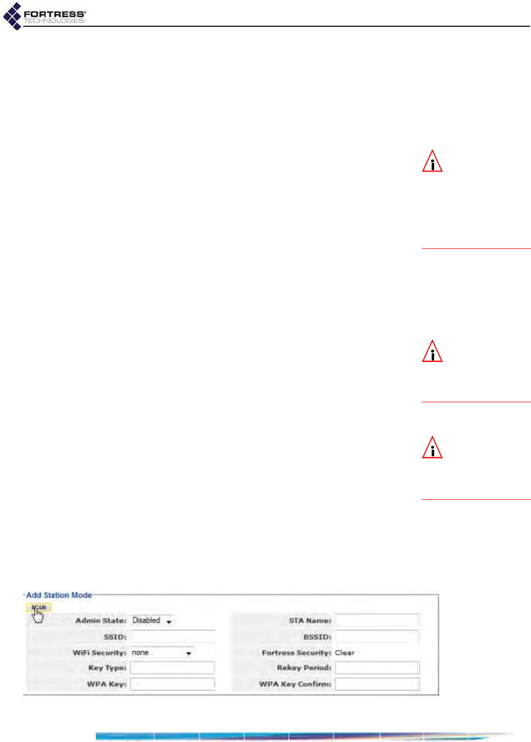
Bridge GUI Guide: Network Configuration
81
4In the Radio Settings screen’s New/Edit BSS frame, enter
new values for the settings you want to change (described
in sections 3.3.4.1 through 3.3.4.14, above).
5Click APPLY in the upper right of the screen (or CANCEL your
changes).
3.3.5 ES210 Bridge STA Settings and Operation
NOTE:
Station Mode
does not support
802.11n radio opera-
tion. You must set the
radio Band to 802.11a or
802.11g before you can
add a Station Interface
(refer to Section 3.3.2.2).
Configuring a STA Interface on the ES210 Bridge radio causes
the Bridge to act as a dedicated WLAN client device, or station,
rather than as an AP or a wireless bridge (or FP Mesh Point).
An ES210 Bridge configured with such an interface is in Station
Mode. Only a single STA Interface is permitted on a given
Bridge, and when one is present, no additional wireless
interface of any type can be configured.
Station Mode is supported only the ES210 Bridge.
A STA Interface can only bridge between a wireless AP and one
or more Ethernet devices on the ES210 's clear Ethernet
port(s), meaning Ethernet ports on which Fortress Security is
Disabled (Section 3.7.4). In addition, no wired (Ethernet)
bridging can occur when the ES210 Bridge is in Station Mode.
NOTE:
On the
ES210, the
aux
port
is labeled
Ethernet
on
the chassis; the
wan
port,
Ethernet (WAN)
.
For example, on an ES210 on which the aux port is clear and
the wan port is encrypted (the defaults), a typical Station Mode
setup would use the aux port to connect one or more Ethernet
devices. If Fortress Security is Disabled on the WAN port, it can
be used in the same way. Devices on a clear Ethernet port
cannot, however, communicate with devices on an encrypted
Ethernet port when the Bridge is in Station Mode.
NOTE:
The ES210
Bridge radio can
alternatively support up
to four
BSS
interfaces.
Refer to Section 3.3.4.
You can preconfigure the ES210 Bridge’s STA Interface with the
settings required to connect to a specific network. Alternatively,
you can scan for available networks within range and select
one to use to create the STA Interface for the ES210 Bridge.
The scan function for a Station Mode ES210 Bridge is
supported through a preconfigured interface that operates
transparently to Bridge GUI users to detect networks within
range of the Bridge. You must enable the ES210 Bridge’s
Station Mode function before you can scan for a network or
preconfigure a STA Interface. You must enable the radio before
you can scan for a network to connect to.
Figure 3.16. Simple View
Add Station Mode
settings frame, ES210

Bridge GUI Guide: Network Configuration
82
Refer to the relevant step-by-step instructions in Section
3.3.5.11, Establishing an ES210 Bridge STA Interface
Connection, for preconfiguring the interface or creating it
through the ES210 Bridge’s scanning function.
3.3.5.1 Station Administrative State
Admin State simply determines whether the interface is Disabled
or Enabled. A newly created STA Interface is Enabled by default.
3.3.5.2 Station Name and Description
In order to create a STA Interface, you must specify a STA
Name of up to 254 alphanumeric characters to identify the
interface in the ES210 Bridge configuration.
You can optionally provide a Description of the interface of up to
100 characters, only in Advanced View.
3.3.5.3 Station SSID
When you SCAN for wireless networks within range and choose
one to which to associate, the SSID of the network you select
will be automatically added as the STA Interface SSID.
If you are manually creating a STA Interface in advance of
connecting to a particular network, you must specify the
network SSID for the ES210 Bridge to associate to.
3.3.5.4 Station BSSID
To disable roaming among multiple APs with the same SSID,
you can specify the MAC address of a single wireless AP to
which the ES210 Bridge STA Interface is permitted to
associate.
When you SCAN for wireless networks within range, you can
automatically fill in the BSSID field when you choose a network
to associate to by clicking on the BSSID displayed (instead of
the SSID) to select it.
3.3.5.5 Station WMM
When Wi-Fi Multimedia QoS (Quality of Service) is Enabled on
the STA Interface, it advertises that it is capable of WMM. If the
AP that the STA Interface associates to is also capable of and
enabled for WMM, the AP will respond to the Station Mode
Bridge with this information and WMM will be used for the
association. If the AP is not capable of and enabled for WMM,
having WMM Enabled on the STA Interface will have no effect.
WMM is Disabled by default for a STA Interface.
If the association is made to a BSS configured on another
Fortress Bridge to serve as a wireless AP (Wireless Bridge
Disabled, refer to Section 3.3.4.3) and the WMM settings on
both the BSS and the STA Interface are Enabled, WMM will be
used for the association.

Bridge GUI Guide: Network Configuration
83
In a WMM-enabled association, packets sent from the Bridge
include WMM tags that permit traffic from the Bridge to be
prioritized according to the information contained in those tags.
You can configure WMM for the STA Interface only in Advanced
View.
3.3.5.6 Station Fragmentation and RTS Thresholds
The RTS Threshold allows you to configure the maximum size
of the frames the STA Interface sends without using the RTS/
CTS protocol. Frame sizes over the specified threshold cause
the interface to first send a Request to Send message and then
receive a Clear to Send message from the destination device
before transmitting the frame.
The RTS Threshold is measured in bytes. A value of zero (0)
disables the function (the default), or whole values between 1
and 2345 are accepted.
The Frag. Threshold allows you to configure the maximum size
of the frames the STA Interface sends whole. Frame sizes
larger than the specified threshold are broken into smaller
frames before they are transmitted. An acknowledgement is
sent for each frame received, and if no acknowledgement is
sent the frame is retransmitted.
The Frag. Threshold is measured in bytes. A value of zero (0)
disables the function (the default), or whole values between
256 and 2345 are accepted.
You can configure RTS and fragmentation thresholds only in
Advanced View.
3.3.5.7 Station Unicast Rate Mode and Maximum Rate
NOTE: You can
configure the uni-
cast minimum rate in
the Bridge CLI (refer to
the CLI Software
Guide). On a radio us-
ing any 802.11g band,
the default is 1 Mbps.
On a radio using any
802.11a band, the de-
fault is 6 Mbps.
When a STA Interface is configured to use a Unicast Rate Mode
setting of auto (the default), the interface dynamically adjusts
the bit rate at which it transmits unicast data frames—throttling
between the configured Unicast Maximum Rate and the
minimum rate—to provide the optimal data rate for the
connection.
At a Unicast Rate Mode setting of fixed, the interface will use the
configured Unicast Maximum Rate for all unicast transmissions.
Transmission rates are set in megabits per second (Mbps).
Unicast Maximum Rate can be set only to a value greater than
or equal to the minimum rate. Usable values for Unicast
Maximum Rate settings depend on the Band setting for the
radio on which the STA Interface is configured, as shown in
Table 3.8.
Table 3.8. Usable STA Rate Settings (in Mbps) per Radio Band Setting
1 25.56 9 11121824364854
802.11a
802.11g

Bridge GUI Guide: Network Configuration
84
NOTE: Radio Band
settings are cov-
ered in detail in Section
3.3.2.2).
The default Unicast Maximum Rate for a new STA interface is 54
Mbps, which specifies the highest setting possible in either
frequency band.
You can configure Unicast Rate Mode and Unicast Maximum
Rate only in Advanced View.
3.3.5.8 Station Multicast Rate
The bit rate at which a wireless interface sends multicast
frames is negotiated per connection. Multicast Rate sets a floor
for multicast transmissions by specifying the lowest bit rate at
which the STA Interface will send multicast frames.
A STA Interface on a radio configured by default to use the 2.4
GHz 802.11g band has a default Multicast Rate of 1 Mbps, which
is appropriate for an interface using the 2.4 GHz frequency
band. Fortress recommends leaving a STA Interface in the
802.11g band at the default Multicast Rate of 1.
A STA Interface on a radio fixed on, or configured by default to
use, the 5 GHz 802.11a band has a default Multicast Rate of
6Mbps, which is appropriate for an interface using the 5 GHz
frequency band. Fortress recommends leaving a STA Interface
in the 802.11a band at the default Multicast Rate of 6.
You can configure Multicast Rate only in Advanced View.
3.3.5.9 Station Fortress Security Status
Fortress Security is displayed view-only for the STA Interface.
Fortress’s MSP (Mobile Security Protocol) cannot be applied to
the STA Interface, so the field will always display Clear.
3.3.5.10 Station Wi-Fi Security Settings
Your selection in the Wi-Fi Security field of the Add Station Mode
frame determines the additional fields you must configure for
that setting.
Wi-Fi Security: None
By default, no Wi-Fi security is applied to traffic on a STA
Interface. Traffic on a STA Interface with a Wi-Fi Security setting
of None is unsecured.
WPA, WPA2 and WPA2-Mixed Security
NOTE: Enterprise
WPA and WPA2
modes require an 802.1X
authentication service to
be available, as part of
the Bridge configuration
(Section 4.3.2.7) or exter-
nally (Section 4.3.1).
WPA (Wi-Fi Protected Access) and WPA2 are the enterprise
modes of WPA (as distinguished from the pre-shared key
modes described below). You can specify that WPA or WPA2 be
used exclusively by the STA Interface, or you can configure it to
be able to use either by selecting WPA2-Mixed.
WPA and WPA2 use EAP-TLS (Extensible Authentication
Protocol-Transport Layer Security) to authenticate network
connections via X.509 digital certificates. In order for a Bridge
in station mode to successfully negotiate a WPA/WPA2 client
connection, you must have specified a locally stored key pair
and certificate to use to authenticate the Bridge as an EAP-TLS

Bridge GUI Guide: Network Configuration
85
peer and at least one CA (Certificate Authority) certificate must
be present in the local certificate store. Refer to Section 6.2.1
for guidance on configuring an EAP-TLS key pair and digital
certificate.
On the Add Station Mode screen, these additional settings
apply to WPA, WPA2 and WPA2-Mixed selections:
Rekey Period - specifies the interval at which new pair-wise
transient keys (PTKs) are negotiated or 0 (zero), which
disables the rekeying function: the interface will use the
same key for the duration of each session seconds. Specify
a new interval in whole seconds between 0 and
2147483647, inclusive. No Rekey Period is specified by
default.
NOTE: Unlike
Suite B Key Estab-
lishment (Section 4.1.3),
the Suite B TLS Cipher
option is available re-
gardless of whether
Suite B is licensed on the
Bridge (Section 6.3).
TLS Cipher - specifies the list of supported cipher suites,
the sets of encryption and integrity algorithms, that the
Bridge will send to the 802.1X authentication server:
All - the default, supports both Legacy and Suite B cipher
suites (as described in the next two items)
Legacy - supports Diffie-Hellman with RSA keys
(DHE-RSA-AES128-SHA and DHE-RSA-AES256-SHA)
Suite B - supports Diffie-Hellman with ECC keys
(ECDHE-ECDSA-AES128-SHA and ECDHE-ECDSA-
AES256-SHA)
In EAP-TLS, the authentication server selects the cipher
suite to use from the list of supported suites sent by the
client device (or rejects the authentication request if none of
the proposed suites are acceptable).
Subject Match - optionally provides a character string to
check against the subject Distinguished Name (DN) of the
authentication server certificate. Each RDN (Relative
Distinguished Name) in the sequence comprising the
certificate DN is compared to the corresponding RDN in the
string provided. Wildcard characters cannot be used.
Certificate Hash - optionally provides a 64-character hash
value to check against the hash value of the authentication
server certificate. When the Certificate Hash field is empty,
the default, no hash value check is performed.
WPA Strict Check - optionally enables strict checking of key
usage and extended key usage extensions in the
authentication server certificate. Strict key usage checking
is Enabled by default.
You can configure TLS Cipher, Certificate Hash, Subject Match
and WPA Strict Check only in Advanced View.
WPA-PSK, WPA2-PSK and WPA2-Mixed-PSK Security
WPA-PSK (Wi-Fi Protected Access) and WPA2-PSK are the
pre-shared key modes of WPA (as distinguished from the
enterprise modes described above). You can specify that WPA-
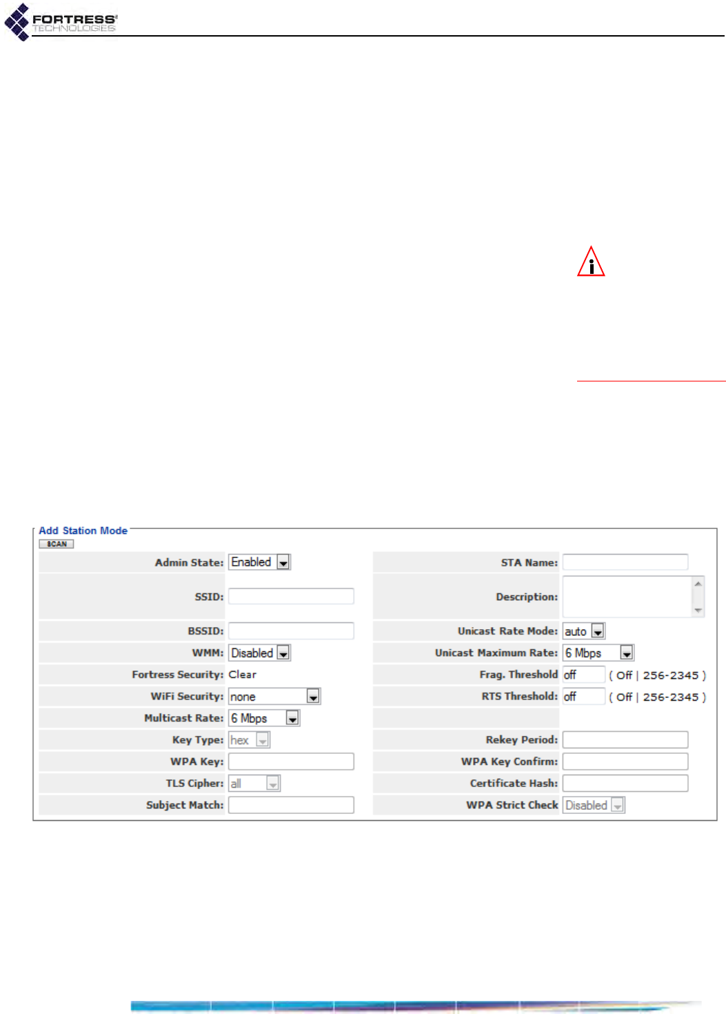
Bridge GUI Guide: Network Configuration
86
PSK or WPA2-PSK be used exclusively by the STA Interface, or
you can configure it to be able to use either by selecting WPA2-
Mixed-PSK.
Pre-shared key mode differs from enterprise mode in that PSK
bases initial key generation on a user-specified key or
passphrase instead of through digital certificates. Like
enterprise-mode, PSK mode generates encryption keys
dynamically and exchange keys automatically with connected
devices at user-specified intervals.
NOTE:
The
TLS Ci-
pher
,
Subject Match
,
Certificate Hash
and
WPA
Strict Check
fields do not
apply (and are greyed
out) when
WPA-PSK
,
WPA2-PSK
or
WPA2-
Mixed-PSK
are selected.
On the Add Station Mode screen, these additional settings
apply to WPA-PSK, WPA2-PSK and WPA2-Mixed-PSK selections:
Rekey Period - specifies the interval at which new keys are
negotiated. Specify a new interval in whole seconds
between 1 and 2147483647, inclusive, or 0 (zero) to permit
the same key to be used for the duration of the session.
Key Type - determines whether the specified key is an ascii
passphrase or a hexadecimal key.
WPA Key and Confirm WPA Key - specify the preshared key
itself, as:
a plaintext passphrase between 8 and 63 characters in
length, when ascii is selected for Key Type, above.
a 64-digit hexadecimal string, when hex is selected for
Key Type, above.
Figure 3.17. Advanced View Add
Station Mode
settings frame, ES210
3.3.5.11 Establishing an ES210 Bridge
STA Interface
Connection
Table 3.9 shows which Add/Edit Station Mode settings appear in
the two GUI views.

Bridge GUI Guide: Network Configuration
87
When Station Mode is enabled, you can scan for available
wireless networks in range and select one to connect to, or you
can configure the STA Interface in advance to connect to a
specific network.
To scan for available networks and choose one to connect to:
If the network you will be connecting to uses WPA, WPA2 or
WPA2-Mixed to authenticate connecting devices, you must
import a valid EAP-TLS digital certificate for the STA Interface
before the ES210 Bridge will be permitted to connect. Refer to
Section 6.2 for guidance.
If the network you will be connecting to uses WPA-PSK, WPA2-
PSK or WPA2-Mixed-PSK, you will be required to enter a valid
pre-shared key for the STA Interface, as described below,
before the ES210 Bridge will be permitted to connect. Refer to
WPA-PSK, WPA2-PSK and WPA2-Mixed-PSK Security in
Section 3.3.5.10 for more on the pre-shared key.
1Log on to the Bridge GUI through an Administrator-level
account and select Configure -> Radio Settings from the
menu on the left.
2If you are configuring one or more Advanced View settings
(see tables 3.5 and 3.9), click ADVANCED VIEW in the upper
right corner of the page. (If not, skip this step.)
3Preconfigure the radio on which you will create the STA
Interface with settings that will permit it to scan for the
network you want to connect to. Refer to Section 3.3 for
guidance.
4In the Radio Settings frame for the radio configured in Step
3, under STA Interface, click the ENABLE STATION button to
display the ADD STATION and DELETE STATION.
5Click the ADD STATION button.
Table 3.9. STA Interface Settings
Simple & Advanced Views Advanced View Only
Admin State Description
STA Name WMM
SSID Frag. Threshold
BSSID RTS Threshold
Wi-Fi Security Unicast Rate Mode
Key Type Unicast Maximum Rate
Rekey Period Multicast Rate
WPA Key/Key Confirm TLS Cipher
Certificate Hash
Subject Match
WPA Strict Check
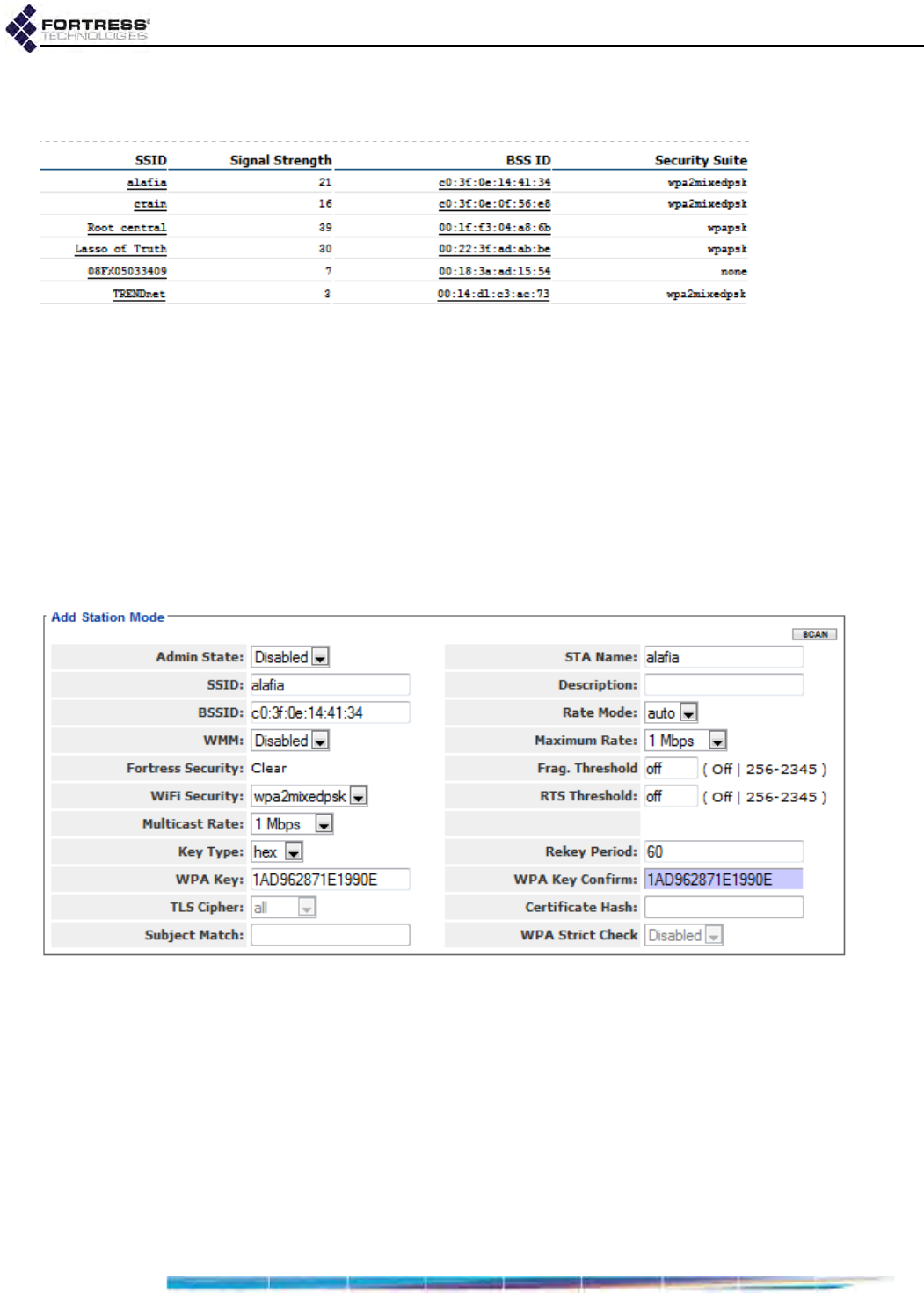
Bridge GUI Guide: Network Configuration
88
6In the Radio screen’s Add Station Mode frame, click the
SCAN button to detect and display available networks.
Figure 3.18. selecting a network for the
STA Interface
to connect to, ES210
7Click to select the network you want the Bridge to connect
to:
Click the network SSID to capture only the network
SSID and Wi-Fi security requirement.
Click the BSS ID to capture both of the above and the
MAC address of the network access point for the BSSID
field on Add Station Mode (in order to restrict the Bridge
to connecting to only that AP).
The Bridge GUI returns the Add Station Mode frame with
settings, as described here, for the network you selected.
Figure 3.19. preconfiguring the
STA Interface
to connect to a network, ES210
8In the Add Station Mode frame, configure the STA Interface
for operation:
If the connection requires a pre-shared key for
authentication, you must specify whether it is an ascii or
hexadecimal string and enter, then re-enter, the correct
key, as described under WPA-PSK, WPA2-PSK and
WPA2-Mixed-PSK Security in Section 3.3.5.10.
or
If the connection uses a digital signature for
authentication, you can optionally configure the

Bridge GUI Guide: Network Configuration
89
additional security options described under WPA,
WPA2 and WPA2-Mixed Security in Section 3.3.5.10.
and
Optionally configure any additional interface settings,
as described in sections 3.3.5.2 through 3.3.5.8.
9Click APPLY in the upper right of the screen (or CANCEL the
action).
To preconfigure a Station Mode ES210 Bridge
to connect to a specific network:
1Log on to the Bridge GUI through an Administrator-level
account and select Configure -> Radio Settings from the
menu on the left.
2If you are configuring one or more Advanced View settings
(see tables 3.5 and 3.9), click ADVANCED VIEW in the upper
right corner of the page. (If not, skip this step.)
3Preconfigure the radio on which you will create the STA
Interface with settings that will permit it to connect to the
same network as the STA Interface. Refer to Section 3.3 for
guidance.
4In the Radio Settings frame for the radio configured in Step
3, under STA Interface, click the ENABLE STATION button to
display the ADD STATION and DELETE STATION buttons.
5 Click the ADD STATION button.
NOTE:
For WPA
PSK authentica-
tion, you must enter the
correct key in the
WPA
Key
/
WPA Key Confirm
fields, as described in
Section 3.3.5.10. These
fields do not apply (and
are greyed out) for En-
terprise WPA modes.
6In the Radio screen’s Add Station Mode frame:
Enter at least a STA Name (Section 3.3.5.2) and the
SSID (Section 3.3.5.3) of the network the Bridge will be
connecting to.
Leave Admin State at the default of Enabled (Section
3.3.5.1).
Optionally preconfigure any additional setting(s)
(described in sections 3.3.5.2 through 3.3.5.10, above).
7Click APPLY in the upper right of the screen (or CANCEL the
action).
8If you are using WPA, WPA2 or WPA2-Mixed Wi-Fi Security,
import a valid EAP-TLS digital certificate to authenticate the
STA Interface on the network it will connect to. Refer to
Section 6.2 for guidance.
9Before connecting the STA Interface to the network, you
must enable the radio on which the STA Interface is
configured (Bridge radios are Disabled by default; refer to
Section 3.3.2.1).
3.3.5.12 Editing or Deleting the ES210 Bridge
STA Interface
An established STA Interface can be reconfigured or deleted.

Bridge GUI Guide: Network Configuration
90
To edit or delete the STA Interface:
1Log on to the Bridge GUI through an Administrator-level
account and select Configure -> Radio Settings from the
menu on the left.
2If you are reconfiguring the existing STA Interface, on the
Radio screen:
If you are reconfiguring one or more Advanced View
settings (see Table 3.8), click ADVANCED VIEW in the
upper right corner of the page. (If not, skip this step.)
Click the EDIT STATION button.
In the Radio screen’s Edit Station Mode frame, enter
new values for the setting(s) you want to change
(described in sections 3.3.5.1 through 3.3.5.10, above).
Click APPLY in the upper right of the screen (or CANCEL
your changes).
or
If you are deleting the STA Interface, on the Radio screen:
Click the DELETE STATION button.
3.3.5.13 Enabling and Disabling ES210 Bridge Station Mode
Station Mode is disabled by default, in which state the
preconfigured scanning interface used for network detection is
disabled. You must enable the function before you can
manually configure a STA Interface or scan for a network.
To enable or disable Station Mode:
If one or more BSSs have been configured on the ES210
Bridge radio, you must delete all BSSs before you can enable
Station Mode (refer to Section 3.3.4).
If a STA Interface is present, you must delete it before you can
disable Station Mode (refer to Section 3.3.5.12).
1Log on to the Bridge GUI through an Administrator-level
account and select Configure -> Radio Settings from the
menu on the left.
2Change the Station Mode state:
If you are enabling Station Mode, click the ENABLE
STATION button.
or
If you are disabling Station Mode, click the DISABLE
STATION button.
Station Mode must be disabled on the ES210 Bridge radio,
before you can configure a BSS on the radio (refer to Section
3.3.4).

Bridge GUI Guide: Network Configuration
91
3.4 Basic Network Settings Configuration
The basic settings that establish the Bridge’s presence on the
network are configured in the Network Configuration frame on
Configure -> Administration, described in sections 3.4.1 and
3.4.2, below.
The Bridge’s system clock and, optionally, NTP (network time
protocol) configuration are set in the Time Configuration frame
of the same screen, as described in Section 3.4.3.
The Bridge’s global bridging function is also configured on
Configure -> Administration, in the Bridging Configuration frame,
and described in Section 3.2
The Bridge’s Ethernet interfaces are also individually
configurable, on Configure -> Ethernet Settings, as described in
Section 3.7.
3.4.1 Hostname, Domain and DNS Client Settings
The Bridge’s configuration settings must include a Hostname,
which by default is based on the hardware series to which the
Bridge belongs (ES-) and its MAC address.
You can optionally identify redundant external Domain Name
System servers (Preferred DNS and Alternate DNS) for the
Bridge.
In Advanced View, you can change the Bridge’s default Domain
name, ftimesh.local.
Bridge software itself includes a standard network DNS
service, enabled by default, which uses the domain name
configured here. If the Bridge cannot resolve a DNS request
internally, it will forward the request to the external servers
configured here.
Refer to Section 3.6.2 for additional information on the internal
DNS server and additional configuration options.
When FastPath Mesh is licensed and enabled, Bridge
functionality additionally includes independent name
distribution within the FastPath Mesh network without the need
for any DNS server, using the Bridge’s configurable Domain.
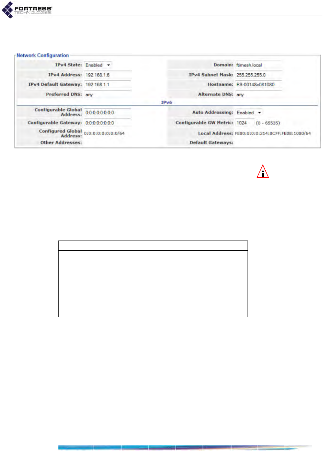
Bridge GUI Guide: Network Configuration
92
Configure these settings on the Bridge GUI’s Network
Configuration screen.
Figure 3.20. Advanced View
Network Configuration
frame, all platforms
NOTE: When en-
abled (the de-
fault), the Bridge’s
internal DNS service is
preferred over either ex-
ternal server, forward-
ing only those DNS
requests that cannot be
resolved internally.
Preferred DNS and Alternate DNS- provide addresses of
external Domain Name System servers on the network or
specifies no network DNS server with any, which maps to
an IP address of 0.0.0.0, the default for both settings.
Leaving both settings at their defaults (or later specifying
0.0.0.0 addresses for both) effectively disables the
Bridge’s ability to query external DNS servers.
Domain - specifies the Bridge’s local domain name.
To configure hostname and DNS Client settings:
1Log on to the Bridge GUI through an Administrator-level
account and select Configure -> Administration from the
menu on the left.
2If you are changing the Bridge’s local domain name, select
ADVANCED VIEW in the upper right corner of the page. If not,
skip this step.
3In the Administration screen’s Network Configuration frame,
enter new values for the settings you want to configure
(described above).
4Click APPLY in the upper right of the screen (or RESET
screen settings to cancel your changes).
Table 3.10. Network and IPv4 Configuration Settings
Simple & Advanced Views Advanced View Only
IPv4 State Domain
IPv4 Address
IPv4 Subnet Mask
IPv4 Default Gateway
Hostname
Preferred DNS
Alternate DNS

Bridge GUI Guide: Network Configuration
93
3.4.2 IP Configuration
The Bridge supports Internet Protocol version 4 (IPv4) and
Internet Protocol version 6 (IPv6).
IPv4 is enabled by default. When it is disabled, the Bridge's
management IP address neither accepts or sends IPv4
packets.
IPv6 is always enabled on the Bridge, a state which is not user
configurable.
3.4.2.1 IPv4 Configuration
The settings that configure Internet Protocol version 4 on the
Bridge include:
IPv4 State - adds the Bridge’s IPv4 address—and therefore
the Bridge itself—to the IPv4 network (Enabled) or removes
the Bridge’s address (and the Bridge) from the network
(Disabled). IPv4 is Enabled by default.
IPv4 Address - establishes an IPv4 network address for the
Bridge’s management interface. The default IPv4 address
is 192.168.254.254; it is normally changed during installation.
IPv4 Subnet Mask - provides the correct IPv4 subnet mask
for the Bridge’s management interface.
IPv4 Default Gateway - provides the IP address of the
default IPv4 gateway for the Bridge’s subnet.
In order to re-access the Bridge’s management interface after
changing the Bridge’s IPv4 settings, you must enter the
Bridge’s new IP address into a new instance of your browser.
3.4.2.2 IPv6 Configuration
NOTE: Fortress’s
FastPath Mesh
functionality includes
independent IPv6 ad-
dressing, which can
supply additional IPv6
ULAs (Unique Local
Addresses, refer to Sec-
tion 3.2.1).
Internet Protocol version 6 is always enabled on the Bridge.
You can choose to allow all IPv6 settings to be automatically
configured on the Bridge, opt to manually configure the global
address and IPv6 gateway/metric, or use both manually and
automatically configured global addresses.
When IPv6 Auto Addressing is Enabled (the default) and there is
an IPv6 router on the network configured to provide the global
prefix, the Bridge will automatically configure a compatible IPv6
global address for itself, displayed under Other Addresses. If
additional IPv6 routers are present, auto-addressing will
configure additional IPv6 global addresses.
If a network IPv6 router is configured to do so, it will additionally
supply its own address as one of the Bridge’s IPv6 Default
Gateways, with the appropriate metric. If more than one IPv6
router is present on the network and so configured, the
additional routers will also appear on the list of IPv6 Default
Gateways, with their metrics.
If you choose to manually configure IPv6 settings, these
include:

Bridge GUI Guide: Network Configuration
94
Auto Addressing - configures the Bridge to learn IPv6 global
prefixes from network routers (Enabled, the default) or to
use only a locally established global address (Disabled).
Configurable Global Address - manually establishes an IPv6
global network address—which must be within the IPv6
global scope—for the Bridge’s management interface.
Configurable Gateway - manually provides the IP address of
the default gateway for the Bridge’s IPv6 subnet. The
default gateway address must be a compatible link-local or
global address (i.e., lie within the same prefix as either the
global address or the link-local address).
If no default gateway is necessary (i.e., you are configuring
the Bridge for use on a private network unconnected to
other OSI Layer 3 networks), you can leave Default
Gateway at its default setting of all zeros.
Configurable GW Metric - establishes the IPv6 metric, or
relative routing cost, for the Configurable Gateway, allowing
it to be assigned a preference relative to the automatically
assigned default gateways.
The rest of the settings in the IPv6 portion of the Network
Configuration frame provide complete information about the
current IPv6 configuration and are view-only (whether or not
Auto Addressing is in effect).
Configured Global Address - normally shows the manually
configured IPv6 network address. There can, however, be
several seconds’ delay before a change in Configurable
Global Address takes effect and is displayed in the view-
only Configured Global Address field.
Local Address - shows the Bridge’s link local IPv6 network
address, which is automatically generated regardless of
whether Auto Addressing is in effect.
Other Addresses - shows all automatically configured IPv6
addresses for the Bridge, including router-configured
addresses and, when FP Mesh is licensed and enabled,
the RFC-4193 unique local address (Section 3.2.1).
Each displayed address of any type additionally shows the
applicable IPv6 subnet prefix length following the address
itself, separated by a slash (ex. /64).
Default Gateways - lists all network gateways, whether
manually configured or active network IPv6 routers
configured to automatically supply their addresses and
metrics (shown in parentheses).
You can configure and view all IPv4 and IPv6 settings in Simple
View.

Bridge GUI Guide: Network Configuration
95
To configure IP settings:
1Log on to the Bridge GUI through an Administrator-level
account and select Configure -> Administration from the
menu on the left.
2In the Network Configuration frame, enter new values for
those settings you want to configure (described in sections
3.4.2.1 and 3.4.2.2).
3Click APPLY in the upper right of the screen (or RESET
screen settings to cancel your changes).
3.4.3 System Clock and NTP Client Configuration
You should set the Bridge’s internal clock at installation,
regardless of whether you enable its NTP (Network Time
Protocol) function.
3.4.3.1 System Date and Time Configuration
Configure the Bridge’s local System Date, System Time and
Time Zone in the Time Configuration frame.
System date and time settings are accessible regardless of the
current Bridge GUI view.
Figure 3.21. Simple View
Time Configuration
frame, all platforms
The Bridge’s internal clock is set in UTC (Universal Time
Coordinated) by default. The Bridge CLI includes an option to
set time on the Bridge in local time (refer to the CLI Software
Guide); no such option is available in the Bridge GUI.
Table 3.11. IPv6 Network Configuration Settings
Configurable Settings
Configurable Global Address
Auto Addressing
Configurable Gateway
Configurable GW Metric
View-Only Settings
Configured Global Address/prefix length
Local Address/prefix length
Other Addresses/prefix lengths
Default Gateways (metrics)
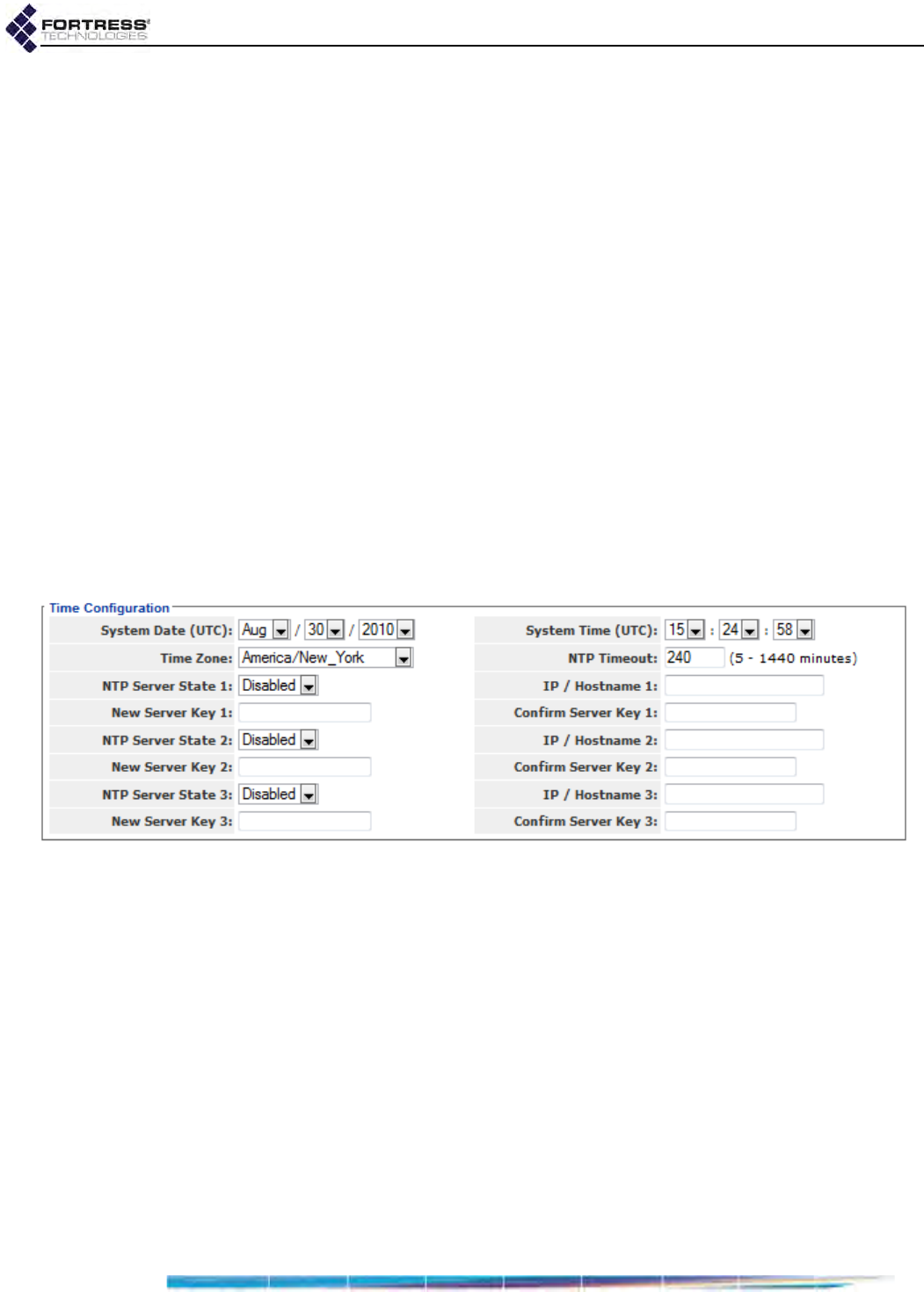
Bridge GUI Guide: Network Configuration
96
3.4.3.2 NTP Client Configuration
In Advanced View, after you have set the Bridge’s internal clock
to within 1000 seconds of the current time on the network, you
can enable the Bridge to synchronize its clock with the time
disseminated by up to three configured NTP servers.
Once the Bridge’s system clock is successfully synchronized
with NTP server time, NTP manages the drift between the time
on the Bridge (the NTP client) and the time maintained by the
NTP server(s) for the network. If the Bridge is out of sync with
NTP server time, NTP automatically corrects the Bridge’s
system clock.
If an NTP server is configured with a shared key to
authenticate NTP transactions and you specify that key on the
Bridge, the Bridge will require the shared key for NTP
transactions with that server. If you do not specify a key for a
configured NTP server, the Bridge will synchronize its clock
with that of the NTP server without shared-key authentication.
The Bridge supports up to three NTP servers.
NTP Timeout applies globally to the configured server(s). Three
settings establish each NTP server individually.
Figure 3.22. Advanced View
Time Configuration
frame, all platforms
NTP Timeout - globally determines the interval, in minutes
from 5 to 1440, of silence from configured NTP servers
after which you will be notified that the Bridge cannot reach
any of its configured and enabled NTP servers. The default
NTP Timeout is 240 minutes.
Server State 1–3 - establishes whether the NTP server
(when configured) will be used (Enabled) to set system time
on the Bridge. All three are Disabled by default.
IP /Hostname 1–3 - provides the IP address or fully qualified
hostname of the NTP server.
New/Confirm Server Key 1–3 - provides the key in effect for
the NTP server.
The Bridge’s NTP client function is disabled by default, and no
NTP servers are configured.
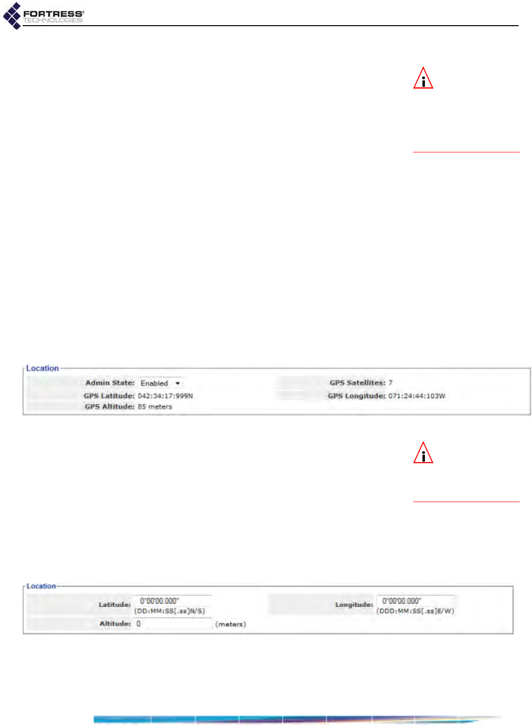
Bridge GUI Guide: Network Configuration
97
To configure system clock and NTP:
NOTE: When NTP
is enabled, the val-
ues provided by the
NTP server overwrite
manually configured
System Date and Time
values.
1Log on to the Bridge GUI through an Administrator-level
account and select Configure -> Administration from the
menu on the left.
2If you are configuring NTP client settings, select ADVANCED
VIEW in the upper right corner of the page. If not, skip this
step.
3In the Administration screen’s Time Configuration frame,
select/enter new values for the settings you want to
configure (described above).
4Click APPLY in the upper right of the screen (or RESET
screen settings to cancel your changes).
3.5 Location or GPS Configuration
Only the ES210 Bridge is equipped with a GPS (Global
Positioning System) receiver and associated antenna port.
When the feature is Enabled (the default) and a GPS antenna
connected, the ES210 uses the signals of GPS satellites in
range to triangulate its exact position on the globe. It
dynamically displays this information in Location fields and in
Topology View details (on Monitor -> Topology View, refer to
Section 5.4).
Figure 3.23. GPS
Location
settings frame, ES210
NOTE: The ES210
GPS antenna port
is shown in the Fortress
ES210 Secure Wireless
Bridge Hardware Guide.
At the default Admin State of Enabled, you can observe current
readings of the Bridge’s GPS Longitude, GPS Latitude and GPS
Altitude in the Location frame on Configure -> Administration (in
the formats described below for manual entry), along with a
count of GPS Satellites in contact with the Bridge.
On other model Fortress Bridges (or on the ES210, when the
GPS function is Disabled), you can optionally configure fixed
settings to reflect the Bridge’s physical position on the globe.
Coordinates entered are shown only here (and for the Bridge
CLI show location command).
Figure 3.24.
Location
settings frame, ES440, ES520, ES820, FC-
X
Manually establish a Bridge’s Location with standard settings
for:

Bridge GUI Guide: Network Configuration
98
Latitude and Longitude - specify the Bridge’s global
coordinates in degrees, minutes and seconds, north/south
or east/west in the format:
DD:MM:SS.ssN/S/E/W, with no spaces
You need only specify whole seconds. You can optionally
specify the Bridge’s coordinates to the 100th second.
Altitude - specifies the Bridge’s altitude in whole meters
above sea level.
No manual Location is set by default.
To enable GPS or manually configure the Bridge’s location:
1Log on to the Bridge GUI through an Administrator-level
account and select Configure -> Administration from the
menu on the left.
2In the Location frame, enter new values into the Location
settings you want to change.
3Click APPLY in the upper right of the screen (or RESET
screen settings to cancel your changes).
3.6 DHCP and DNS Services
Bridge functionality includes standard, user configurable
network IPv4 and IPv6 DHCP (Dynamic Host Control Protocol)
and DNS (Domain Name System) services.
3.6.1 IPv4 and IPv6 DHCP Services
When the Bridge’s internal DHCP servers are enabled, the
Bridge provides standard DHCP services to network DHCP
clients.
You can observe current DHCP leases on Monitor ->
Connections -> DHCP Leases tab.
Internal DHCP services use the internal DNS server (see
below) and the locally configured DNS client settings and
domain name on Configure -> Administration -> Network
Configuration (refer to Section 3.4.1).
The IPv4 DHCP server uses the locally configured IPv4 Default
Gateway in the upper half of the Network Configuration frame
(refer to Section 3.4.2.1). The IPv6 DHCP server uses the IPv6
default gateway(s) in the lower IPv6 portion of the frame,
including those established automatically and the manually
configured default gateway (if present). Refer to Section
3.4.2.2 for more on IPv6 addressing.
The Bridge’s internal DNS server is enabled by default, and the
Bridge can be configured to use external network DNS servers,
when available (refer to Section 3.4.1). If the Bridge’s DNS
server and DNS client functions are enabled simultaneously,
and the internal DHCP service is unable to resolve a name to
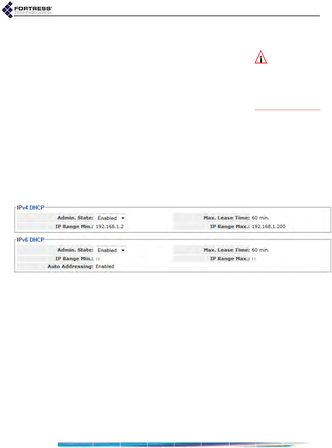
Bridge GUI Guide: Network Configuration
99
an IP address, the Bridge will forward the request to up to two
network DNS servers.
NOTE: Fortress’s
FastPath Mesh
functionality includes
automatic RFC-4193
IPv6 addressing inde-
pendent of network IPv6
DHCP services (see Sec-
tion 3.2.1).
When FastPath Mesh is used for bridging and the FastPath
Mesh network is attached to a conventional hierarchical
network, internal DHCP services obtain default gateway and
DNS server settings from locally configured values. In addition,
the Bridge passes DHCP client IP address-to-name mapping to
the independent FastPath Mesh name resolution function,
permitting all nodes in the FP Mesh network to reach DHCP
clients by name, as well as by IPv4 address. Refer to Section
3.2.1.1 for more on FastPath Mesh bridging.
Both internal DHCP servers are Disabled by default.
If you enable the Bridge’s internal IPv4 DHCP server, you must
specify the lowest and highest IPv4 addresses in the Bridge’s
IPv4 DHCP address pool.
If you enable the Bridge’s internal IPv6 DHCP server and leave
Auto Addressing at its default of Enabled, you do not need to
manually define the service’s address pool. Alternatively, you
can optionally disable Auto Addressing, and specify the pool’s
start and end IPv6 addresses.
Figure 3.25. Advanced View
DHCP
configuration frames, all platforms
Although address formats are different, the four basic settings
that configure the Bridge’s IPv4 and IPv6 DHCP services are
the same:
Admin. State - determines whether the Bridge will serve IP
addresses to network devices (Enabled) or not (Disabled).
Both DHCP services are Disabled by default.
Max. Lease Time - determines the period of time leases
issued to DHCP clients by the service are valid, in minutes
between 1 and 525,600 (365 days). The default for both
servers is 60 minutes.
IP Range Min. and IP Range Max. - define the start and end
IP addresses within the service’s DHCP address pool:
For the IPv4 DHCP service, you must enter IPv4
addresses in the usual format when you enable the
server.
For the IPv6 DHCP service:

Bridge GUI Guide: Network Configuration
100
If Auto Addressing will be left at its default of Enabled
(see below), you should leave these settings at their
defaults (::).
If you opt to disable Auto Addressing, you must enter
IPv6 addresses in the usual format.
The Bridge’s IPv6 DHCP server has an additional setting:
Auto Addressing - configures the IPv6 DHCP server to
automatically define its address pool. When Auto
Addressing is Enabled (the default), the IPv6 server’s
manually configured IP Range Min. and IP Range Max.
should remain undefined (at the default :: setting).
To configure internal DHCP servers:
1Log on to the Bridge GUI through an Administrator-level
account and select ADVANCED VIEW in the upper right corner
of the page, then Configure -> DHCP/DNS from the menu on
the left.
2In the frame for the type of DHCP server you are
configuring, IPv4 DCHP or IPv6 DHCP, select/enter new
values for the settings you want to configure (described
above).
3Click APPLY in the upper right of the screen (or RESET
screen settings to cancel your changes).
When Bridge DHCP servers are enabled, the fields that
configure their address pools are grayed out to indicate that
you cannot reconfigure the address pool while the server is
running. You must disable the server to re-enable these fields
for editing.
3.6.2 DNS Service
When enabled (the default), the Bridge’s internal DNS server
provides local network name-to-IP address resolution, for both
IPv4 and IPv6 addresses.
The Bridge’s domain name, ftimesh.local by default, is
configured in Advanced View in the Network Configuration
frame on Configure -> Administration.
The Bridge’s DNS service learns name-to-IP address mapping
for locally resolved names from any of three sources:
user entries to the DNS Host to IP Map (see below)
when a DHCP server is available, from DHCP requests
when FastPath Mesh is used for bridging, from name-to-IP
address mappings learned by the other Mesh Points (i.e.,
peer nodes) in the FP Mesh network
For manual entries, you can map a single name to multiple IP
address and associate a single IP address with multiple
names.
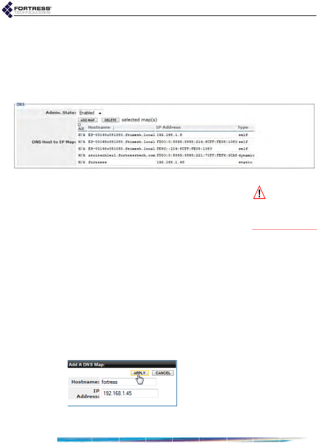
Bridge GUI Guide: Network Configuration
101
The Bridge GUI’s DNS Host to IP Map shows all mappings,
which you can sort by ascending or descending Hostname or IP
Address. Each entry is identified by Type, which can be:
self - a mapping for the current Bridge
dynamic - a mapping supplied by a DHCP service or
obtained from other Mesh Points in a FastPath Mesh
network
static - a manually established mapping
Figure 3.26. Advanced View
DNS
configuration frame, all platforms
CAUTION: Dis-
abling the DNS
server internal to a Fast-
Path Mesh Point can de-
grade FP Mesh network
performance.
When FastPath Mesh is used for bridging, the internal DNS
service facilitates name resolution for FP Mesh network nodes
and network resiliency in the absence of an external referral
server. Fortress therefore recommends that the DNS service
be left at its a default of Enabled for FastPath Mesh network
deployment. Refer to Section 3.2.1.1 for more on FastPath
Mesh bridging.
To configure the internal DNS server:
1Log on to the Bridge GUI through an Administrator-level
account and select ADVANCED VIEW in the upper right corner
of the page, then Configure -> DHCP/DNS from the menu on
the left.
2In the DNS frame, in Admin. State, determine whether the
internal service is Enabled (the default) or Disabled.
3Click APPLY in the upper right of the screen (or RESET
screen settings to cancel the change).
4In the same frame, if you want to manually map one or
more device names in the Bridge’s local domain to specific
IPv4 and/or IPv6 address(es):
Click ADD MAP.
Figure 3.27. Advanced View
Add a DNS Map
dialog, all platforms

Bridge GUI Guide: Network Configuration
102
In the resulting Add a DNS Map dialog, enter a network
device’s Hostname and, in IP Address, the IPv4 or IPv6
address you want to the name to map to.
Click APPLY (or CANCEL the addition).
Repeat these steps for any additional name-to-IP
address associations you want to manually add to the
internal DNS service.
NOTE: DNS en-
tries learned dy-
namically from network
DHCP services or Fast-
Path Mesh peer nodes
cannot be manually de-
leted.
5In the same frame, if you want to remove manually
configured name-to-IP address mappings:
If you want to delete one or a selected group of manual
mappings, click to place a check in the box beside each
entry you want to delete; then the DELETE button above
the list.
or
If you want to delete all manual mappings, click All to
place a check in the boxes of all manually configured
entries; then click the DELETE button above the list.
3.7 Ethernet Interface Settings
Fortress Bridges are equipped for wired network connections
with varying numbers of Ethernet ports with various optional
characteristics.
Compare your Bridge’s model number (on the Administration
Settings screen under System Info.) to Table 3.12 above to
determine the number of Ethernet ports with which the Bridge
you are configuring is equipped, how they are labeled on the
Table 3.12. Fortress Bridge Model Ethernet Ports
series
Fortress
model
# of
Eth
ports HW label GUI label takes
PoE serves
PoE fiber
option default
encryption
ES
ES820 2 Ethernet1 wan no no no encrypted
Ethernet2 aux no no no clear
ES520 9 WAN wan1 yes no no encrypted
1–8 lan1–lan8 no yes no clear
ES440 2 Ethernet1 wan yes no no encrypted
Ethernet2 aux no no no clear
ES210 2 Ethernet (WAN) wan no no no encrypted
Ethernet aux no no no clear
FC
FC-X3
Encrypted enc no no yes encrypted
Unencrypted clr no no yes clear
AUX aux no no no clear

Bridge GUI Guide: Network Configuration
103
chassis and in the GUI, and each port’s default Fortress
Security setting.
Bridge Ethernet ports can be configured per port, according to
the requirements of your implementation. Access per-port
settings through Configure -> Ethernet Settings.
Figure 3.28. Simple View
Ethernet Settings
screen, ES210, ES440, ES820
Software labels cannot be changed. Ethernet Settings screens
display each port’s view-only Name.
3.7.1 Port Administrative State
Admin. State determines whether the port is Enabled or
Disabled. All ports are Enabled by default.
3.7.2 Port Speed and Duplex Settings
Speed determines whether the port will transmit and receive
data at a specified speed (10 Mbps or 100 Mbps) or
automatically adjust to the highest possible speed (Auto, the
default).
Duplex determines whether the port will allow only Full Duplex
communication, only Half Duplex communication, or
automatically determine whether to use full or half duplex
communication according to the duplex communication in use
by connected devices (Auto, the default).
NOTE: Core can
only be selected
for FastPath Mesh Mode
when the Fortress Securi-
ty selection for the port
(Section 3.7.4) matches
that of the FP Mesh net-
work overall (Section
3.2.1.2). Normally, For-
tress Security should be
Enabled for both.
3.7.3 Port FastPath Mesh Mode and User Cost Offset
Two settings configure the port’s FastPath Mesh attributes:
FastPath Mesh Mode - establishes the port’s role in the FP
Mesh network.
Core - configures the interface to connect to other FP
Mesh-enabled Fortress Mesh Points (MPs)
Access - configures the interface to connect Non-Mesh
Points (NMPs) to the FP Mesh network.
User Cost Offset - allows you to weight the port more
heavily in the FP Mesh cost equation in order to make it
less attractive relative to other interfaces. Enter a non-
negative integer between 0 (zero) and 4,294,967,295.
The higher the offset, the less attractive the interface. A
neighbor with the maximum cost (4,294,967,295) will
never be used to route traffic. The default is 0 (zero).
Network Cost Weighting and the FP Mesh cost equation
are described in Section 3.2.1.5.
FastPath Mesh bridging is described in Section 3.2.1.
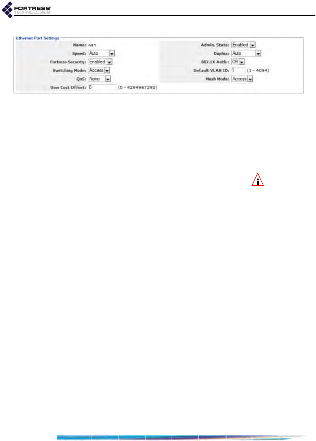
Bridge GUI Guide: Network Configuration
104
Figure 3.29. Advanced View
Ethernet Port Settings
screen,
wan
port, ES210, ES440, ES820
3.7.4 Port Fortress Security
When Fortress Security is Enabled on a port, traffic on that port
is subject to Fortress’s Mobile Security Protocol (MSP), as
configured on the Bridge itself (refer to Section 4.1). Such a
port is also known as an encrypted port.
When Fortress Security is Disabled, traffic on the port is exempt
from Fortress’s MSP.
NOTE: The cur-
rent Cleartext traf-
fic setting is shown in
the upper left of all
Bridge GUI screens.
If Cleartext Traffic is Enabled on the Bridge (Section 4.1.10),
configured cleartext devices (Section 4.5.3) are exempt from
MSP and permitted to pass clear text on the Bridge’s encrypted
ports.
Refer to Table 3.12, above, to determine the default Fortress
Security settings for a given Bridge model’s Ethernet ports.
3.7.5 Port 802.1X Authentication
Enabling 802.1X Auth. requires that devices connecting to the
port are 802.1X supplicants successfully authenticated by the
802.1X service configured on or for the Bridge (Enabled) or
allows non-802.1X authenticated devices to connect (Disabled).
802.1X is disabled on all ports by default. (Refer to Section 4.3
to configure an 802.1X server for the Bridge.)
3.7.6 Port Default VLAN ID and Port Switching Mode
Two settings configure the port’s VLAN handling:
Default VLAN ID associates the port with the specified
VLAN ID. The Bridge supports VLAN IDs 1–4094. If the
VLAN ID you enter is not already present on the VLAN
Active ID Table (Section 3.9.3), it will be added. The default
is 1.
Switching Mode establishes the port’s behavior with regard
to data packet VLAN tagging.
Access - (the default) configures the port to accept only:
(1) packets that do not contain VLAN tags and
(2) specialized priority-tagged packets, which provide
support for Ethernet QoS exclusive of VLAN
implementations.

Bridge GUI Guide: Network Configuration
105
NOTE: There is
only one VLAN
trunk per Bridge, used
by all Trunk ports. It is
defined by the Bridge’s
VLAN Active ID Table
(Section 3.9.3).
Trunk - configures the port to accept incoming packets
with any VLAN tag in the VLAN ID table and to send
packets with their VLAN tagging information
unchanged, including 802.1p priority tags, provided that
the port’s QoS override function is disabled (see QoS,
below).
Refer to Section 3.9 and to Table 3.14 for a complete
description of VLAN handling on the Bridge.
To support QoS, the Bridge treats incoming priority-tagged
packets (characterized by a VLAN ID of zero) as untagged
packets, but marks them for sorting into QoS priority queues
according to the user-priority value contained in their VLAN
tags. (Refer to Section 3.8 for details on the Bridge’s QoS
implementation).
You can configure VLAN port settings only in Advanced View.
3.7.7 Port QoS Setting
QoS enables/disables the port’s Quality of Service override
feature. When enabled, the port’s QoS function forces all traffic
on the port into the specified QoS priority queue and adds a
priority marking for that queue to each packet. Bridge priority
markings replace any 802.1p Quality of Service (QoS) tags
included in the packets.
If a packet received on the port is transmitted wirelessly, the
Bridge uses the priority marking to determine its WMM (Wi-Fi
Multimedia) priority level. If the packet egresses over an
Ethernet port with a VLAN Switching Mode of Trunk (described
above), the Bridge priority marking is inserted into the packet’s
VLAN tag for QoS processing. (Ethernet ports with a Switching
Mode of Access do not send VLAN tags and so cannot include
priority tags.)
By default, the QoS override is set to None on all ports, which
disables the function. Alternatively, you can choose to
associate all traffic on the port with the Bridge’s Low, Medium,
High or Critical priority queue. (Refer to Section 3.8 for more
information on QoS priority queues.)
You can configure QoS settings only in Advanced View.
3.7.8 Port Power over Ethernet
NOTE: The ES520
can supply a maxi-
mum 36 Watts of PoE
overall and up to 16 W
per vertically stacked
port-pair, to connected
PDs. (Refer to the ES520
Hardware Guide for de-
tails.)
Only the ES520 Bridge can act as Power over Ethernet Power
Sourcing Equipment (PoE PSE), and only via the eight ports of
its internal LAN switch, labeled lan1–lan8 in the Bridge GUI.
The PSE setting determines whether the port will serve PoE to
connected Powered Devices (PDs). PSE is Disabled by default.
It must be Enabled on every port through which you want to
supply PSE, i.e., on all ports connected to PDs.
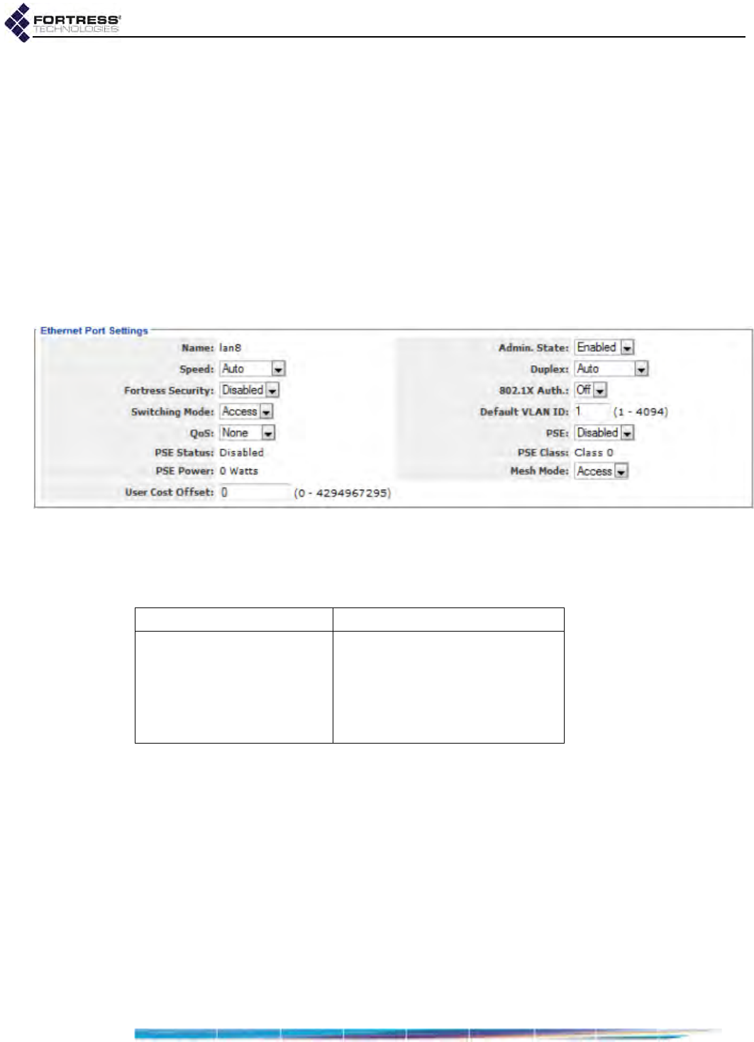
Bridge GUI Guide: Network Configuration
106
Ethernet devices that do not support PoE, or non-Powered
Devices, can use a PSE-enabled port with no effect on such
devices or on PSE operation.
If you are powering a PoE Class 3 or Class 0 device on a given
port, you may want to leave PSE Disabled on the port above/
below it. Vertically stacked ports share a fuse that can bear
only a single PoE Class 0/3 device. Plugging a PoE powered
device into the remaining port in the pair will trip the shared
fuse, when PSE is Enabled on that port (and the overall
maximum PoE supply would not be exceeded by the addition).
PSE connection capacities and limitations are described in full
in Fortress’s ES520 Secure Wireless Bridge Hardware Guide.
Figure 3.30. Advanced View
Ethernet Port Settings
screen,
lan
port, ES520
Table 3.13 shows which Ethernet Settings appear in the two
GUI views.
3.7.9 Configuring Ethernet Ports
1Log on to the Bridge GUI through an Administrator-level
account and select Configure -> Ethernet Settings from the
menu on the left.
2If you are configuring one or more Advanced View settings
(see Table 3.13), click ADVANCED VIEW in the upper right
corner of the page and then the EDIT button for the port you
want to configure.
3In the Ethernet Settings frame, enter new values for those
settings you want to configure, described above.
4Click APPLY in the upper right of the screen (or CANCEL your
changes).
Table 3.13. Ethernet Port Settings
Simple & Advanced Views Advanced View Only
Admin. State Switching Mode
Speed Default VLAN ID
Duplex QoS
Fortress Security PSE
802.1X Auth.

Bridge GUI Guide: Network Configuration
107
3.8 QoS Implementation
The Bridge supports Quality of Service (QoS) expediting for
wireless traffic according to the WMM® (Wi-Fi Multimedia)
subset of the IEEE standard 802.11e, QoS for Wireless LAN,
and for Ethernet traffic according to the IEEE standard 802.1p,
Traffic Class Expediting.
The Bridge marks traffic that contains 802.1p user-priority tags
with the associated QoS priority level. The default mapping of
priority tags to priority queues conforms to IEEE standard
802.1D, MAC Bridges, Annex G, but is user configurable (see
below). Traffic received without user-priority tags is marked for
Medium (or Best Effort) QoS handling.
Ethernet QoS
On Ethernet, QoS tags are conveyed as part of the VLAN tags
that can be included in packet headers. If the Bridge is
configured to use VLANs, it will apply the user-priority values in
the VLAN tags of the traffic it receives according to the
mapping specified on Configure -> Ethernet Settings.
The Bridge can send 802.1p user-priority tags over Ethernet
only when VLAN Mode is Enabled (Section 3.9) and only over
ports with a VLAN Switching Mode of Trunk (Section 3.7.6),
since these are the only conditions under which the Bridge
sends VLAN-tagged packets.
When VLANs are disabled, the Bridge drops regular VLAN
traffic but accepts specialized priority-tagged packets in order
to support Ethernet QoS exclusive of a VLAN implementation.
Priority-tagged packets are those which include a VLAN tag
with a VLAN ID of zero (or null-value VLAN ID). The Bridge
sorts this traffic into QoS priority queues according to the user-
priority information contained in the VLAN tag. The Bridge
cannot send priority-tagged packets.
The Bridge’s per-port QoS override function (Section 3.7.7)
overrides any priority tagging information in the traffic on that
port, marking all traffic on the port for sorting into the specified
QoS priority queue.
Wireless QoS
When enabled on the BSS, WMM Quality of Service is in effect
for bridge links, the connections formed between Bridge radio
BSSs with Wireless Bridge Enabled (Section 3.3.4.3).
NOTE: To deter-
mine/configure
WMM QoS capability
for a given device, con-
sult its documentation.
QoS is negotiated individually for devices connecting to a
WMM-enabled BSS configured to provide wireless access
(Section 3.3.4). If the connecting device supports and is
enabled for WMM QoS, the Bridge prioritizes traffic for the
device according to its priority tags. Traffic from devices that do
not send priority tags is marked for Medium (or Best Effort) QoS
handling.

Bridge GUI Guide: Network Configuration
108
WMM is enabled by default on new BSSs (refer to Section
3.3.4.7).
Wireless packets can convey QoS priority tags directly in their
802.11 headers. When no VLAN tags are present, the Bridge
sorts wireless traffic into QoS priority queues according to
these tags. If a wireless packet also contains a VLAN tag, the
Bridge applies the user-priority tag conveyed in the VLAN tag,
rather than in the 802.11 header.
On ES210 Bridges in Station Mode (refer to Section 3.3.5),
WMM is also enabled by default on new STA Interfaces (as
described in Section 3.3.5.5).
Priority Tag-to-Queue Mapping
By default, 802.1p user-priority values are mapped to priority
queues according to IEEE standard 802.1D, MAC Bridges,
Annex G:
Critical - packets are delivered ahead of all other QoS levels.
WMM categorizes this level of service as Voice. The IEEE
specification recommends Critical QoS for traffic tagged with
802.1p user-priority values 6 and 7.
High - packets are delivered after Critical and ahead of lower
QoS levels. WMM categorizes this level of service as Video.
IEEE recommends High QoS for traffic tagged with user-priority
values 4 and 5.
Medium - is Best Effort delivery: packets are delivered after
higher QoS levels, but ahead of Low priority traffic. IEEE
recommends Medium QoS for traffic tagged with user-priority
values 0 (zero) and 3 and for untagged traffic.
Low - is for Background traffic: packets are delivered after all
other QoS levels. IEEE recommends Low QoS for traffic
tagged with user-priority values 1 and 2.
Packets received with no priority information and not subject to
an Ethernet-port QoS override are sorted into the Medium QoS
priority queue.
You can disable QoS on the Bridge by assigning all eight
802.1p tags to the same priority level.
You can configure Ethernet Quality of Service only in Advanced
View
Figure 3.31. Advanced View
802.1p QoS Tag Priorities
frame, all platforms
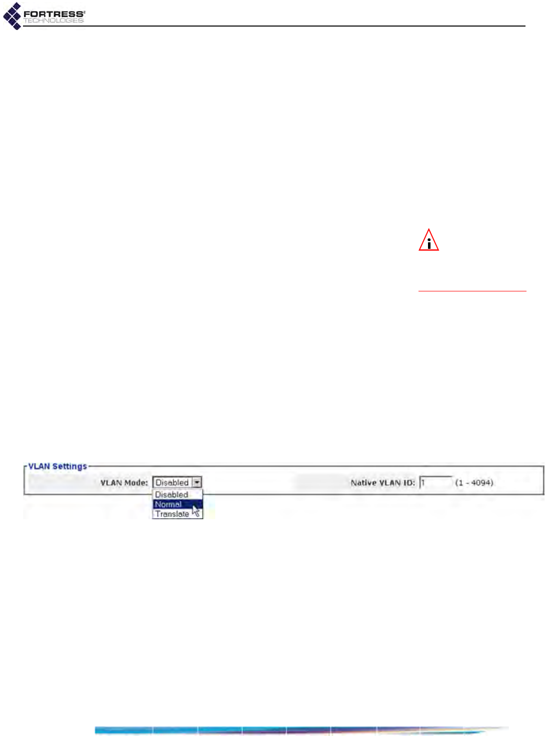
Bridge GUI Guide: Network Configuration
109
To reconfigure QoS priority tag-to-queue mapping:
1Log on to the Bridge GUI through an Administrator-level
account and select ADVANCED VIEW in the upper right corner
of the page, then Configure -> Ethernet Settings from the
menu on the left.
2In the Ethernet Settings screen’s 802.1p QoS Tag Priorities
frame, use the pull down menus to change how 802.1p
priority tags are assigned to QoS priority queues.
3Click APPLY in the upper right of the screen (or RESET
screen settings to cancel your changes).
3.9 VLANs Implementation
NOTE: VLANs are
incompatible with
FastPath Mesh and STP
Bridging Modes (Section
3.2).
When Bridging Mode is Off (STP is selected by default, refer to
Section 3.2), the Bridge supports multiple virtual local area
networks (VLANs), either by transparently passing VLAN
tagging information or by translating VLAN tags according to a
user-defined routing map.
Each of the Bridge’s Ethernet ports and each BSS configured
on its radio(s) can be configured to use a specified VLAN. The
VLANs configured for these interfaces are automatically added
to the Bridge’s table of active VLAN IDs (described below).
At its default configuration, the Bridge has a VLAN Mode setting
of Disabled. The only VLAN configured on the Bridge is the
native VLAN with a VLAN ID of 1. VLAN 1 is specified for all of
the Bridge’s interfaces by default and 1 is the sole VLAN ID
configured on the VLAN Active ID Table.
You can configure the Bridge’s VLAN mode, VLAN IDs and
native VLAN.
Figure 3.32. Advanced View
VLAN Settings
frame, all platforms
3.9.1 VLAN Mode
Which VLAN mode to use is largely determined by your
network configuration and its requirements. These instructions
assume that you are familiar with VLAN concepts and
implementation.
VLAN Mode: Disabled
The default VLAN Mode of the Bridge is Disabled, in which
VLAN traffic is not passed. Packets received with VLAN tags
traffic are discarded. Any per port VLAN settings are
disregarded.

Bridge GUI Guide: Network Configuration
110
External switches running in port-based VLAN modes require
that the Bridge use the VLAN mode Disabled.
VLAN Mode: Normal
In Normal VLAN Mode, the Bridge passes the VLAN tag’s VLAN
ID exactly as it is received, while encrypting/decrypting the rest
of the data normally. The same tags are passed to and from the
clear and encrypted interfaces. Per port VLAN settings are
applied.
The Bridge can support up to 48 VLANs in Normal mode.
If the Bridge must support trunking between switches, bridging
between multiple Fortress Bridges, or an access point with
multiple SSIDs connected directly to the Bridge, use Normal
mode.
As shown in Table 3.14, Access interfaces can receive and
transmit only untagged traffic. Traffic received on an Access
interface is tagged internally with the ingress interface’s Default
VLAN ID, and this tag is removed again at egress.
Trunk ports pass most tagged traffic with its tags unchanged,
except that traffic tagged with the same VLAN ID as the ingress
interface’s Default VLAN ID is sent untagged.
The Bridge’s Ethernet port Switching Mode and Default VLAN ID
settings are covered in Section 3.7.6. Configuring these setting
for radio BSSs is described in Section 3.3.4.5
VLAN Mode: Translate
In Translate VLAN Mode, the Bridge alters the VLAN ID in the
VLAN tag according to a routing map (or translation table) that
Table 3.14.
Normal
Mode VLAN Handling
received traffic VLAN traffic handling
interface
Switching Mode VLAN tagging on ingress internal on egress
Access untagged accept tag w/ ingress interface
Default VLAN ID
tag = egress interface
Default VLAN ID: send untagged
tag ≠ egress interface
Default VLAN ID: drop
tagged drop
Trunk
untagged accept tag w/ ingress interface
Default VLAN ID send untagged
tag = ingress interface
Default VLAN ID accept preserve tag
as received send untagged
tag ≠ ingress interface
Default VLAN ID and
is in VLAN Active ID Table accept preserve tag
as received send tagged as received
tag ≠ ingress interface
Default VLAN ID and is
not in VLAN Active ID Table drop

Bridge GUI Guide: Network Configuration
111
you configure for each VLAN that the Bridge secures. The
routable VLAN IDs received on clear interfaces are translated,
according to the routing map, into non-routable IDs and
transmitted on an encrypted interface, and vice versa (non-
routable VLAN IDs received on encrypted interfaces are
translated into routable IDs and transmitted on a clear
interface).
NOTE: VLAN
translation occurs
only on traffic received
in one zone (clear or en-
crypted) and transmit-
ted in the other zone.
VLAN IDs passed from
one interface to another
within the same zone
are not translated.
Routable VLAN IDs must therefore be part of a trunk in the
clear zone, and Non-Routable VLAN IDs must be part of a trunk
on an encrypted port. VLAN IDs that are passed within the
same zone do not have to be present in the VLAN routing map.
The Bridge can support up to 24 VLANs in translate mode:
each translation requires two VLAN IDs, for a maximum of 48
VLAN IDs on the VLAN translation map.
If the Bridge's encrypted and clear interfaces reside on the
same OSI layer-2 switch, use Translate mode.
3.9.2 Native VLAN
The native VLAN can be used as management VLAN, allowing
you to use tagged traffic to manage the Bridge.
On an interface with a VLAN Switching Mode of Trunk, you can
access the Bridge’s management interface only with packets
tagged with the Bridge’s Native VLAN ID. You can manage the
Bridge on an interface with a VLAN Switching Mode of Access
only with untagged packets and only when the interface’s
Default VLAN ID matches the Bridge’s global Native VLAN ID.
You can reconfigure the Bridge to use a native VLAN ID other
than 1 (the default), which automatically adds the new number
to the Bridge’s VLAN ID table (described in Section 3.9.3). If
the new ID is already present on the VLAN ID table, it will
simply be selected as the Native VLAN ID.
VLAN functions are available only in Advanced View.
To configure basic VLAN settings
1Log on to the Bridge GUI through an Administrator-level
account and select ADVANCED VIEW in the upper right corner
of the page, then Configure -> VLAN from the menu on the
left.
2In the VLAN Settings frame, enter new values for those
settings you want to configure (described above).
3Click APPLY in the upper right of the screen (or RESET
screen settings to cancel your changes).
4If you selected a VLAN Mode of Normal or Translate, refer to
Section 3.9.3 to configure additional VLANs. For Translate
mode, refer to Section 3.9.4 to create VLAN map records.
You cannot configure VLANs when STP or FastPath Mesh is
selected as the Bridge’s Bridging Mode (refer to Section 3.2).
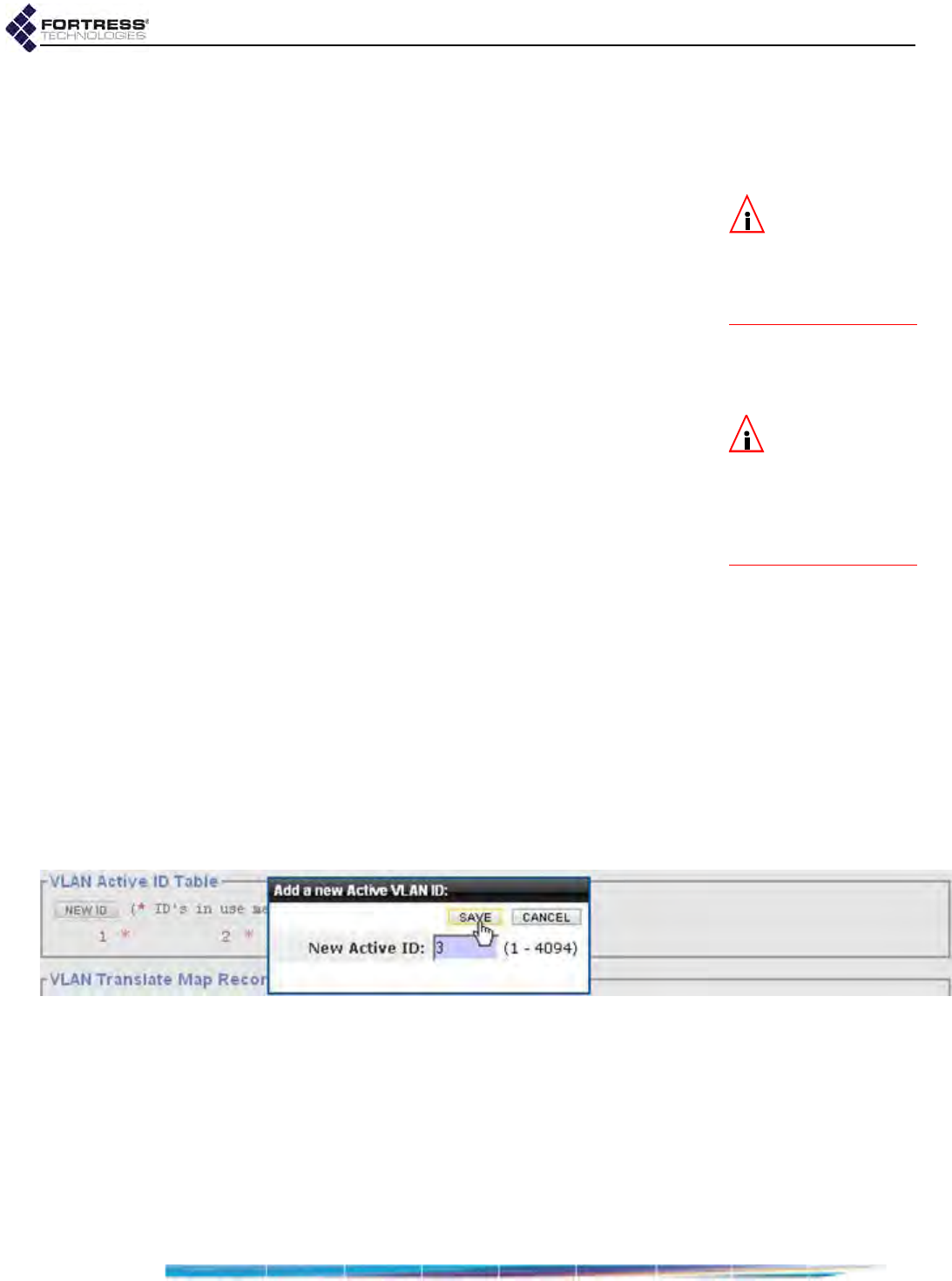
Bridge GUI Guide: Network Configuration
112
3.9.3 VLAN ID Table
The VLAN IDs you use on your network, for the native VLAN
and for translate-mode mapping, are stored in the VLAN ID
Table.
NOTE: There is
only one VLAN
trunk per Bridge, de-
fined by the Bridge’s
VLAN Active ID Table and
used by all Trunk ports.
The contents of the table determine the VLANs available for
assignment to the Bridge’s interfaces. The VLAN ID Table
defines the VLAN trunk for the Bridge, as used by all interfaces
on the Bridge configured as Trunk ports. It is populated through
any of several operations:
If, in Configure -> VLAN -> VLAN Settings (sections 3.9.1
and 3.9.2), you enter a VLAN ID not already present on the
VLAN ID table as the Native VLAN ID, the new VLAN ID is
automatically added to the table.
NOTE: VLAN IDs
added automati-
cally to the VLAN ID ta-
ble will remain on the
table even if the Bridge
is reconfigured to no
longer use them.
If, in Configure -> VLAN -> VLAN Translate Map Records
(Section 3.9.4), you enter a VLAN ID not already present
on the VLAN ID table as a Routable ID or Non-Routable ID,
the new VLAN ID is automatically added to the table.
If, in Configure -> Radio Settings -> BSS Interfaces -> EDIT/
ADD BSS or in Configure -> Switch Settings -> Switchports ->
EDIT, you enter a Default VLAN ID not already present on
the VLAN ID table, the new VLAN ID is automatically added
to the table.
The settings that configure VLAN handling by the Bridge’s
Ethernet ports are described in Section 3.7.6; VLAN
settings for radio BSS interfaces are covered in Section
3.3.4.5.
You can manually add VLAN IDs to the VLAN ID table
(below).
You can configure up to 48 VLAN IDs on the Bridge, using
VLAN ID numbers 1–4094, inclusive. VLAN IDs 0 and 4095 are
reserved for internal use.
Figure 3.33. Advanced View
Add a new Active VLAN ID
dialog, all platforms
VLAN functions are available only in Advanced View.
To manually add VLAN IDs to the Bridge configuration
1Log on to the Bridge GUI through an Administrator-level
account and select ADVANCED VIEW in the upper right corner
of the page, then Configure -> VLAN from the menu on the
left.
2In the VLAN Active ID Table frame, click NEW ID.

Bridge GUI Guide: Network Configuration
113
3In the resulting dialog, enter the ID number of the VLAN
you want to add to the configuration and click OK.
The ID number of VLAN you added will be listed in the VLAN
Active ID Table.
You cannot delete a VLAN ID from the Bridge configuration
while it is in use, as indicated by a red asterisk to the right of
the ID number.
The marked VLAN ID may be in use by one of the Bridge’s
Ethernet interfaces (Section 3.7.6), radio BSS interfaces
(Section 3.3.4.5), or as the Native VLAN (Section 3.9.2); or the
VLAN ID may be part of the VLAN translation map (Section
3.9.4). When you have reconfigured the Bridge so that the
VLAN ID is no longer in use, you will be able to delete the
VLAN ID from the configuration, as indicated by the checkbox
to the right of the ID number.
To delete VLANs from the Bridge configuration
1Log on to the Bridge GUI through an Administrator-level
account and select ADVANCED VIEW in the upper right corner
of the page, then Configure -> VLAN from the menu on the
left.
2In the VLAN Active ID Table, click to check the box(es) of
the VLAN(s) you want to delete (or check the boxes of all
unused VLAN IDs with ALL).
3Click DELETE.
4Click OK in the confirmation dialog (or Cancel the deletion).
The ID numbers of VLANs you delete will be removed from the
VLAN ID Active Table.
You cannot configure VLANs when STP or FastPath Mesh is
selected as the Bridge’s Bridging Mode (refer to Section 3.2).
3.9.4 VLAN Map Records
If you are using VLAN Translate mode (Section 3.9.1). you
must create a VLAN translation map for your configuration:
To add VLAN map records to the Bridge configuration:
Figure 3.34. Advanced View
VLAN Map Record
frame, all platforms
1Log on to the Bridge GUI through an Administrator-level
account and select ADVANCED VIEW in the upper right corner
of the page, then Configure -> VLAN from the menu on the
left.

Bridge GUI Guide: Network Configuration
114
2In the VLAN Translate Map Records frame, click NEW
RECORD.
3On the resulting Edit VLAN screen, in VLAN Map Record:
In Record Name: enter a descriptive name for the
mapping record.
In Routable ID: enter the routable VLAN ID for packets
passed through the clear zone (to the wired LAN).
In Non-Routable ID: enter the corresponding non-
routable VLAN ID for packets passed through the
encrypted zone (to the WLAN).
4Click APPLY in the upper right of the screen (or CANCEL your
addition).
The mapping records you create display at the bottom of the
VLAN Translate Map Records frame on the VLAN screen.
To edit a VLAN map record
1Log on to the Bridge GUI through an Administrator-level
account and select ADVANCED VIEW in the upper right corner
of the page, then Configure -> VLAN from the menu on the
left.
2In the VLAN Map Records frame click the EDIT button for the
record you want to change.
3Change the settings you want to reconfigure (described
above, and click APPLY in the upper right of the screen (or
CANCEL your changes).
Your changes will be reflected in the record’s entry at the
bottom of the VLAN Map Records frame on the VLAN screen.
To delete VLAN map records
You can delete VLAN map records individually or all at once.
1Log on to the Bridge GUI through an Administrator-level
account and select ADVANCED VIEW in the upper right corner
of the page, then Configure -> VLAN from the menu on the
left.
2In the VLAN Translate Map Records frame:
Click to check the box(es) of the record(s) you want to
delete.
or
Click All to select all map records.
3Click DELETE at the top of the frame.
4Click OK in the confirmation dialog (or Cancel the deletion).
The records you delete are removed from the VLAN Translate
Map Records frame on the VLAN screen.
VLAN functions are available only in Advanced View, and you
cannot configure VLANs when STP or FastPath Mesh is selected
as the Bridge’s Bridging Mode (refer to Section 3.2).
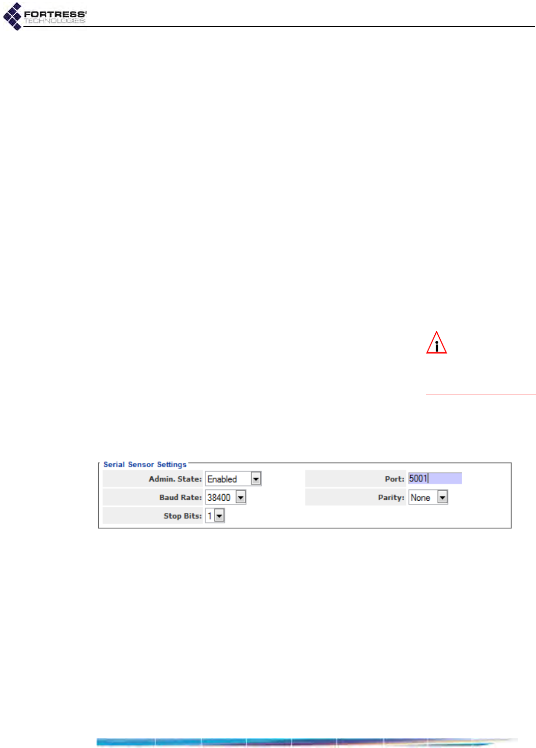
Bridge GUI Guide: Network Configuration
115
3.10 ES210 Bridge Serial Port Settings
The serial port on the front panel of the ES210 Bridge is
configured by default to be used for Console port access to the
Bridge CLI, as other Bridge model serial ports are used.
On the ES210 Bridge, you can reconfigure the serial port to
instead connect the Bridge to an external third-party Serial
Sensor, or another serial device.
When Serial Sensor Settings are Enabled, the serial port
behaves like a serial terminal server, passing data between the
specified TCP (Transmission Control Protocol) port and the
device connected to the serial port. Serial data can be
accessed using telnet ip_addr tcp_port, with no options.
Only one TCP connection at a time is permitted to the Serial
Sensor TCP port. The ES210 Bridge can send data from and to
the connected serial device over any of the Bridge’s wired or
wireless interfaces, under the security provisions configured for
the interface and on the Bridge overall.
3.10.1 Configuring the Serial Port
NOTE: You must
reboot the Bridge
in order to change the
function of the ES210
Bridge serial port.
Enabling Serial Sensor Settings disables the serial port for
Bridge CLI access. The Bridge CLI remains accessible by a
terminal emulation application over an SSH2 (Secure Shell 2)
network connection, provided SSH Access is Enabled (the
default; refer to Section 4.1.6).
Disabling the Serial Sensor function re-enables the port’s
Bridge CLI Console function and automatically returns serial
port settings to the correct values for the Bridge CLI (baud rate:
9600, parity: none, stop bits: 1).
Figure 3.35.
Serial Sensor Settings
frame, ES210
Use Serial Sensor Settings to enable and configure the ES210
Bridge’s serial port to connect to an external serial device.
Admin. State - determines whether the port’s Serial Sensor
function and the rest of the configuration settings in the
Serial Sensor Settings frame are Enabled or Disabled (the
default). You must reboot the ES210 Bridge in order to
change Admin. State, as directed below.
Port - specifies the TCP port for the serial interface. Port
values between 5000 and 65534 are valid; the default is
port 5001.
Baud Rate - specifies the number of bits per second for the
serial connection at 300, 1200, 2400, 4800, 9600 (the
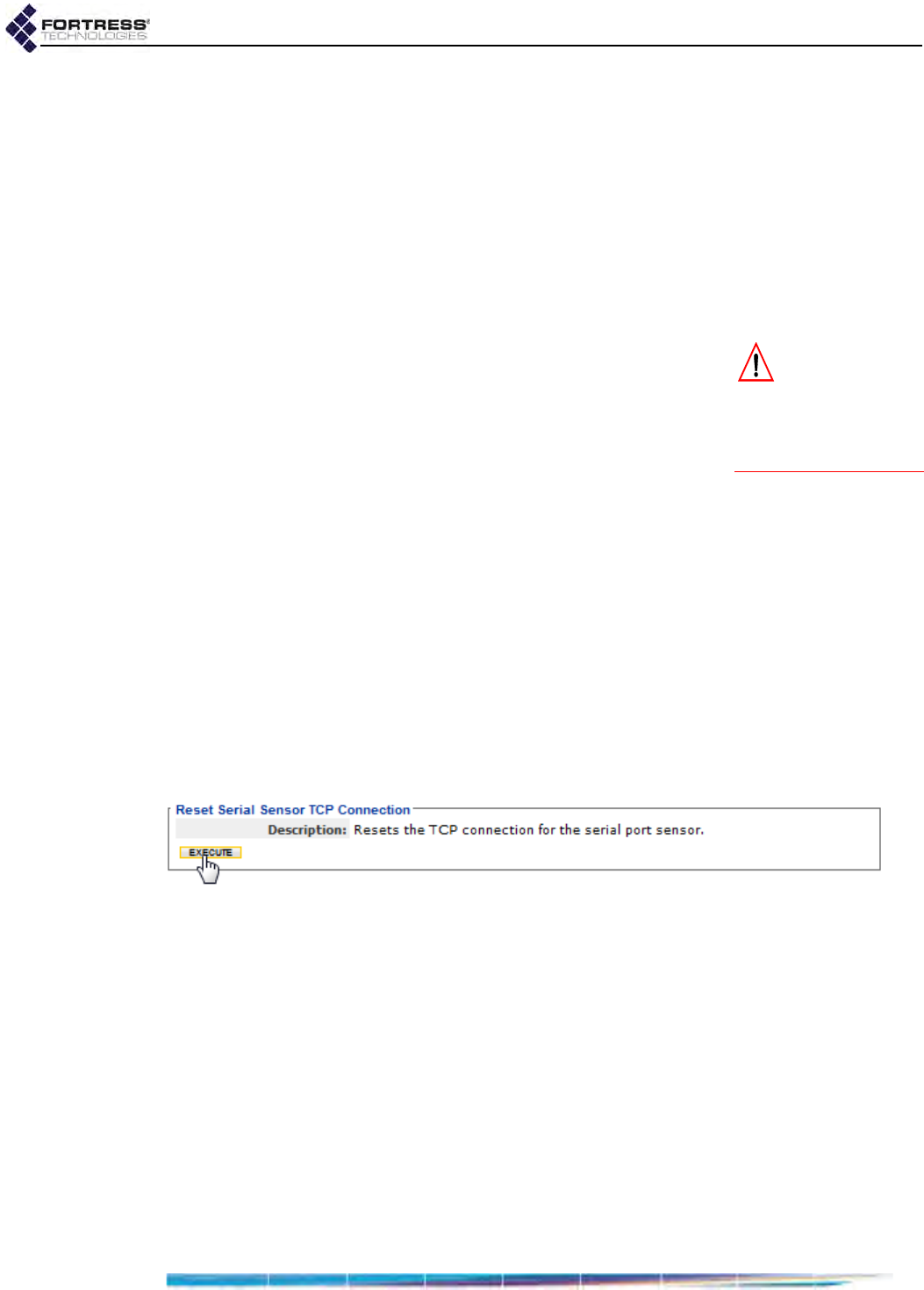
Bridge GUI Guide: Network Configuration
116
automatic setting for the Console port), 19200, or 38400 (the
default when Serial Sensor Settings are Enabled).
Parity - specifies whether the parity bit used for error
checking results in an Even or Odd number of bits per byte
or, with a setting of None (the default), that no parity bit
should be added.
Stop Bits - specifies whether the port should use a stop bit
of 1 (the default) or 2.
The serial port always uses 8 data bits per character and no
hardware or software flow control.
CAUTION: En-
abling the Serial
Sensor function on the
ES210 Bridge disables
management access
through the serial port.
To configure the ES210 serial port:
1Log on to the Bridge GUI through an Administrator-level
account and select Configure -> Serial Sensor from the
menu on the left.
2In the Serial Sensor Settings frame, enter new values for
those settings you want to configure (described above).
3Click APPLY in the upper right of the screen (or RESET
screen settings to cancel your changes).
4If you changed the Admin. State in Step 2, reboot the ES210
Bridge according to the instructions in Section 6.1.2.
Restoring the ES210 Bridge’s factory default configuration
restores the serial port to the default Bridge CLI Console
function.
3.10.2 Resetting the Serial Port
When the ES210 Bridge is enabled for and connected to an
external serial device, you can manually restart the serial port’s
TCP session.
Figure 3.36.
Reset Serial Sensor TCP Connection
frame, ES210
To reset the ES210 serial port TCP session:
1Log on to the Bridge GUI through an Administrator-level
account and select Configure -> Serial Sensor from the
menu on the left.
2In the Reset Serial Sensor TCP Connection frame, click
EXECUTE.
Resetting the serial port has no effect when the Serial Sensor
function is Disabled.
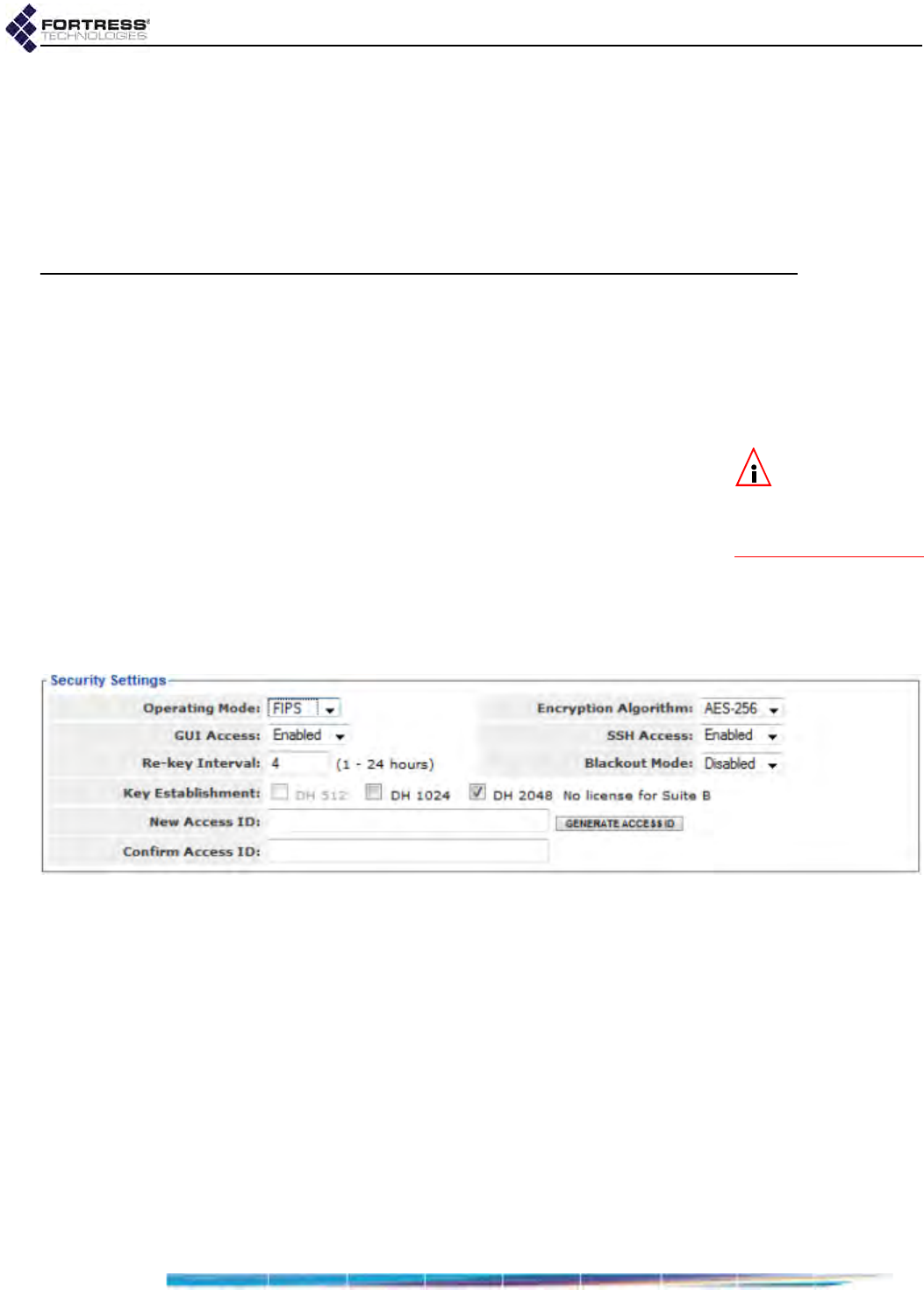
Bridge GUI Guide: Security Configuration
117
Chapter 4
Security, Access, and
Auditing Configuration
4.1 Fortress Security
NOTE: Fortress
MSP is not sup-
ported on an ES210
Bridge in Station Mode
(refer to Section 3.3.5).
The Security Settings frame provides controls for various
aspects of the Bridge’s overall network security provisions:
Fortress MSP (Mobile Security Protocol) functions including
key establishment, data encryption and network Access ID;
FIPS operation; global session timeouts; and several additional
management and network access settings.
A number of Fortress Security Settings are available only in
ADVANCED VIEW. Table 4.1 shows which settings are available
in each view.
Figure 4.1. Simple View, Fortress
Security Settings
frame, all platforms
In addition, administrative password requirements and the
retry, timeout and lockout parameters for administrative
accounts are set on the Security screen, in the Logon Settings
frame (as described in Section 2.2.1).
4.1.1 Operating Mode
The Fortress Bridge can be operated in either of two modes:
Normal or FIPS (the default).
The rigidly enforced administrative requirements of FIPS
operating mode are required by deployments and applications
that must comply with the Federal Information Processing
Standards (FIPS) for cryptographic modules. However, the
high levels of security that can be implemented in Normal
operating mode generally meet or exceed the needs of virtually

Bridge GUI Guide: Security Configuration
118
all networked environments that are not required to comply
with FIPS.
NOTE: Contact
your Fortress rep-
resentative for up-to-
date information on the
Bridge’s FIPS validation
status.
As of this writing, FIPS operating mode in the current version of
Bridge software is in the process of being validated as
compliant with FIPS 140-2 Security Level 2. These Federal
standards enforce security measures beyond those of Normal
operating mode, the most significant of which include:
Only a designated Crypto Officer, as defined by FIPS, may
perform administrative functions on the Bridge and its
Secure Clients. (The preconfigured admin, Administrator-
level, account corresponds to the FIPS Crypto Officer role;
refer to Section 2.2.)
If the Bridge encounters a FIPS Error condition, it shuts
down and reboots, running FIPS self-tests as a normal part
of boot-up. If FIPS self-tests pass, the Bridge will return to
normal operation. If FIPS self-tests fail, before any
interfaces are accessible, the Bridge will again reboot. If the
Bridge is unable to pass power-on self-tests, it will cycle
perpetually through this reboot process. In this case, you
must return the Bridge to your vendor for service or
replacement.
DH-512 and DH-1024 key establishment (Section 4.1.3)
are no longer FIPS 140-2-compliant and are therefore not
compatible with FIPS operating mode.
NOTE: Only devic-
es configured on
the Bridge to pass clear
text on encrypted inter-
faces are permitted to
do so, even when Clear-
text Traffic is enabled.
Regardless of the current operating mode, the Bridge can be
configured to allow unencrypted data on encrypted interfaces
by enabling Cleartext Traffic (refer to Section 4.1.10). In FIPS
terminology, this indicates that the Bridge is in Bypass Mode
(BPM), as selectively permitted clear text can pass, along with
any encrypted traffic, on encrypted interfaces (Ethernet ports or
radio BSSs on which Fortress Security is Enabled).
The Bridge GUI displays the current operating Mode and
Cleartext traffic setting in the status fields in the upper left,
above the main menu (refer to Section 5.1).
4.1.2 MSP Encryption Algorithm
The Bridge supports the strong, AES encryption standard at
these user-specified key lengths:
AES-256 (default)
AES-192
AES-128
All Secure Clients (and other Fortress controller devices)
connecting to the Bridge must be configured to use the same
encryption algorithm as the Bridge. For information on setting
encryption algorithms on Fortress Secure Clients, refer to that
product’s user guide.

Bridge GUI Guide: Security Configuration
119
4.1.3 MSP Key Establishment
You can configure the method that the Bridge and its Secure
Clients (and other connecting controller devices) use to
establish data encryption keys.
NOTE:
On wire-
less networks, sep-
arate multicast packets
are sent for each config-
ured key group. To max-
imize throughput, limit
the number selected.
In Normal operating mode (Section 4.1.1) the Bridge supports
three Diffie-Hellman groups (DH groups) for key
establishment—identified by the size of the modulus, in
numbers of bits, used to generate the secret shared key:
DH-512 (Normal [non-FIPS] operating mode only)
DH-1024 (Normal [non-FIPS] operating mode only)
DH-2048 (default selection)
When operating the Bridge in FIPS mode (Section 4.1.1), you
cannot use DH-512 or DH-1024 key establishment, because
the smaller Diffie-Hellman group moduli are no longer
compliant with FIPS 140-2 Security Level 2.
When NSA (National Security Agency) Suite B5 cryptography
is licensed on the Bridge, an additional elliptic curve Diffie-
Hellman key establishment method is available for selection:
Suite B (specified by the NSA as compliant with the Suite B set
of cryptographic algorithms). When Suite B is not licensed on
the Bridge, the Bridge GUI displays a link to the features
licensing page (refer to Section 6.3).
While a Secure Client can employ only one key establishment
option at a time, the Bridge supports multiple key establishment
selections, allowing connecting Clients to use any enabled key
establishment option.
NOTE: Secure Cli-
ent versions earli-
er than 3.1 support only
DH-512 key establish-
ment. If you need to
support pre-3.1 Secure
Client devices, you
must include DH-512.
A Secure Client logging on to the Bridge must use a key
establishment option enabled on the Bridge. For information on
configuring key establishment on Fortress Secure Clients, refer
to the Secure Client’s user guide.
When two Fortress controller devices are connected, they will
negotiate keys using the highest security option mutually
supported by the devices.
When Suite B key establishment has been licensed on the
Bridge, this option represents the highest available security.
NOTE: DH-512 key
establishment can-
not be selected when a
32-digit Access ID (Sec-
tion 4.1.17) is in effect.
Larger key moduli equate to more security for the standard
Diffie-Hellman group key establishment options, as well.
DH-512 is therefore the least secure DH group, and if you do
not need the Bridge to support Secure Client versions earlier
than 3.1 (which require DH-512), Fortress recommends more
secure key establishment.
Larger key moduli result in somewhat longer initial connection
times.
Refer to the Suite B requirements specific to your site and
implementation for guidance on Suite B.
5. Refer to Footnote 1 on page 2.

Bridge GUI Guide: Security Configuration
120
4.1.4 MSP Re-Key Interval
Fortress Bridges generate new keys at defined intervals,
renegotiating dynamic keys with their Secure Clients whenever
those Clients are logged on. You can specify the re-key
interval, in hours, at values between 1 and 24. The default is 4.
At the default, for example, to decrypt data intercepted over a
12-hour period, a hacker would need to recover three sets of
keys just from the Bridge, quickly enough to employ them
before the next re-key—a highly unlikely possibility. Connecting
devices’ re-keying behaviors would generate additional key
exchanges, and keys from the Bridge alone would not permit
network access.
Every new key negotiation adds network traffic, and the
increased security of shorter re-key intervals should be
balanced against throughput considerations.
4.1.5 Access to the Bridge GUI
In order for the Bridge GUI to be usable, GUI Access must be
Enabled. When GUI Access is Disabled, the Bridge can be
managed exclusively through the Bridge CLI.
Access to the Bridge GUI is Enabled by default.
If you disable the Bridge GUI from within the interface, your
current session will end. You must re-enable the Bridge GUI
from the Bridge CLI before the former will again be accessible
(refer to the CLI Software Guide).
NOTE: The
Bridge’s com-
mand-line interface can
always be accessed via a
direct connection to the
Bridge’s serial Console
port (refer to the CLI
Software Guide).
4.1.6 Secure Shell Access to the Bridge CLI
In order for the Bridge CLI to be accessible via the network,
Secure Shell (SSH®) must be Enabled. When SSH Access is
Disabled, you can access the Bridge CLI exclusively through a
direct connection to its Console port.
SSH Access is Enabled on the Bridge by default.
4.1.7 Blackout Mode
The Blackout Mode setting on the Fortress Bridge globally turns
all chassis LEDs on and off.
When Blackout Mode is Enabled, none of the Bridge’s LEDs will
illuminate for any reason—except for a single, initial blink
(green) of less than half a second, at the beginning of the boot
process. When Blackout Mode is Disabled (the default), the LED
indicators function normally.
You can also enable/disable blackout mode through chassis
controls on some Bridge hardware models (refer to the
Hardware Guide for the Bridge you are configuring) or through
the Bridge CLI (refer to the CLI Software Guide).

Bridge GUI Guide: Security Configuration
121
4.1.8 FIPS Self-Test Settings
The Bridge runs a number of self-tests described in FIPS 140-
2, (Federal Information Processing Standards’ Security
Requirements for Cryptographic Modules).
FIPS tests run—and self-test failures are logged—regardless
of whether it is in FIPS or Normal operating mode. When the
Bridge is in FIPS operating mode, it will additionally shut down
and reboot upon the failure of any FIPS self-test, as required
by FIPS 140-2 (refer to Section 4.1.1).
By default, FIPS tests run when they are automatically
triggered or manually executed (refer to Section 6.1.7). FIPS
tests are triggered regardless of FIPS settings. You cannot turn
triggered FIPS testing off on the Bridge. FIPS test triggers
include any security-related change to the Bridge’s
configuration (deleting a user, for example, or changing the re-
key interval).
You can configure the Bridge to run additional FIPS tests
periodically, and when periodic tests are enabled, you can
configure the FIPS self-test run-interval (the default is 86,400
seconds, or 24 hours).
You can configure the interval at which the random number
generator is reseeded (the default is 86,400 seconds, or 24
hours). You can also determine whether random number
generator (RNG) tests are run routinely: continuous RNG tests
are Enabled by default; when the Bridge is in FIPS operating
mode they cannot be Disabled.
You can configure FIPS self tests only in Advanced View.
4.1.9 Encrypted Data Compression
You can configure whether or not data passed by devices on
an encrypted interface on the Bridge (in the encrypted zone) is
compressed. Data compression in the encrypted zone is
enabled by default.
The compression settings of all Secure Clients (and other
Fortress controller devices) on the Bridge-secured network
must match: either enabled for all devices or disabled for all
devices.
You can enable/disable data compression only in Advanced
View.
4.1.10 Encrypted Interface Cleartext Traffic
By default, cleartext traffic—both received and transmitted—is
blocked on a Bridge’s encrypted interfaces (Ethernet ports or
radio BSS on which Fortress Security is Enabled).

Bridge GUI Guide: Security Configuration
122
NOTE: The cur-
rent Cleartext traf-
fic setting is shown in
the upper left of all
Bridge GUI screens (re-
fer to Section 5.1).
Encrypted-interface cleartext traffic must be enabled to support
AP management rules on the Bridge and Trusted Device
access to the Bridge’s encrypted zone. In FIPS terminology,
when clear text is enabled on the Bridge’s encrypted
interfaces, the Bridge is in FIPS Bypass Mode.
Disabling cleartext traffic on encrypted interfaces after AP
management rules or Trusted Devices have been configured
will not remove them from the configuration. Because these
devices cannot decrypt encrypted traffic, however, the Bridge
will not be able to communicate directly with them until
cleartext traffic is permitted on encrypted interfaces. 802.1X
devices will likewise be unable to access the Bridge-secured
network when cleartext traffic on encrypted interfaces is
blocked.
You can enable/disable cleartext traffic only in Advanced View.
4.1.11 Encrypted Interface Management Access
By enabling or disabling Encrypted Interface Management, you
can control whether or not the Bridge’s management interface
can be accessed on interfaces enabled for Fortress Security
(refer to sections 3.3.4.13 and 3.7.4 for wireless and Ethernet
interfaces, respectively).
Encrypted Interface Management applies to any connection to
an encrypted interface on the current Bridge:
local Fortress Secure Client connections
connections through a remote Fortress controller device
bridging links between networked Fortress Bridges
authorized clear devices when Guest Management is
Enabled (Section 4.1.12, below)
Encrypted Interface Management is Enabled by default.
If Encrypted Interface Management is Disabled, you will be able
to manage the Bridge only through a clear interface (or through
the serial Console port).
You can enable/disable Encrypted Interface Management only in
Advanced View.
4.1.12 Guest Management
You can control whether or not the Bridge’s management
interface can be accessed by authorized cleartext devices
(Section 4.5.3) on encrypted interfaces on the Bridge by
enabling or disabling Guest Management.
Guest Management is Disabled by default, and Trusted Devices
are not allowed to access the Bridge’s management interface.
The Encrypted Interface Management setting (Section 4.1.11,
above) overrules Guest Management. When Encrypted Interface
Management is Disabled, no management access is permitted

Bridge GUI Guide: Security Configuration
123
on any encrypted interface, including by configured cleartext
devices, regardless of the Guest Management setting.
You can enable/disable Guest Management only in Advanced
View.
4.1.13 Cached Authentication Credentials
When a device’s session times out, the device is required to
renegotiate encryption keys in order to reconnect to the
network. When Cached Auth. Credentials is Enabled (the
default), users of devices that have timed out are
reauthenticated transparently, using cached user credentials.
When the Cached Auth. Credentials is Disabled, such users are
prompted to re-enter their usernames and passwords in order
to re-establish their network connections.
You can enable/disable Cached Auth. Credentials only in
Advanced View.
4.1.14 Fortress Beacon Interval
The Fortress Bridge transmits a key beacon at regular intervals
to maintain active, secure connections to other Fortress
devices on the local, Bridge-secured network. This enables
immediate, secure communication between Fortress devices.
You can configure the number of seconds between Fortress
beacons in whole numbers between 1 and 3000, or disable the
Fortress beacon (by entering zero in the interval configuration
field). The default beacon interval of 30 seconds is appropriate
for most networks. Less frequent beacons (longer intervals)
may be desirable where network bandwidth is in short supply.
You can configure the beacon interval only in Advanced View.
4.1.15 Global Client and Host Idle Timeouts
NOTE: Adminis-
trator idle time-
outs (
Section 2.2.1.4
) are
separate from host and
Secure Client devices
idle timeout settings.
You can separately configure Secure Client connections to the
Bridge’s encrypted zone and host connections to the clear
zone to be forcibly ended after a specified period of inactivity.
When local or external authentication is in effect for network
users, the timeout settings configured globally on the
applicable RADIUS server will override the Client Idle Timeout
setting on the Security screen. For more detail on user timeout
settings, refer to Section 4.4.
You can configure Client and host device timeouts, in minutes,
from 1 to 43,200 (30 days). A setting of 0 (zero), disables
timeouts. By default, both types of session timeout after 30
minutes of inactivity.
You can configure the Client and host device idle timeouts only
in Advanced View.
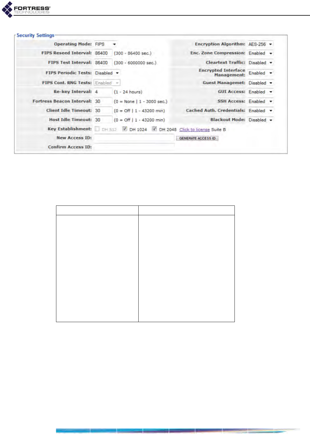
Bridge GUI Guide: Security Configuration
124
Figure 4.2. Advanced View, Fortress
Security Settings
frame, all platforms
4.1.16 Changing Basic Security Settings:
Table 4.1 shows which settings can be configured only in
Advanced View.
1Log on to the Bridge GUI through an Administrator-level
account and select Configure -> Security from the menu on
the left.
2If you are configuring one or more Advanced View settings
(see Table 4.1), click ADVANCED VIEW in the upper right
corner of the page. (If not, skip this step.)
3In the Security screen’s Security Settings frame, enter new
values for the settings you want to change (described in
sections 4.1.1 through 4.1.14, above).
4Click APPLY in the upper right of the screen (or RESET
screen settings to cancel your changes).
Table 4.1. Security Settings
Simple & Advanced Views Advanced View Only
Operating Mode FIPS Reseed Interval
Encryption Algorithm FIPS Test Interval
GUI Access FIPS Periodic Tests
SSH Access FIPS Cont. RNG Tests
Re-key Interval Enc. Zone Compression
Blackout Mode Cleartext Traffic
Key Establishment Secure Client Mgmt.
Access ID Guest Management.
Cached Auth. Credentials
Fortress Beacon Interval
Client Idle Timeout
Host Idle Timeout
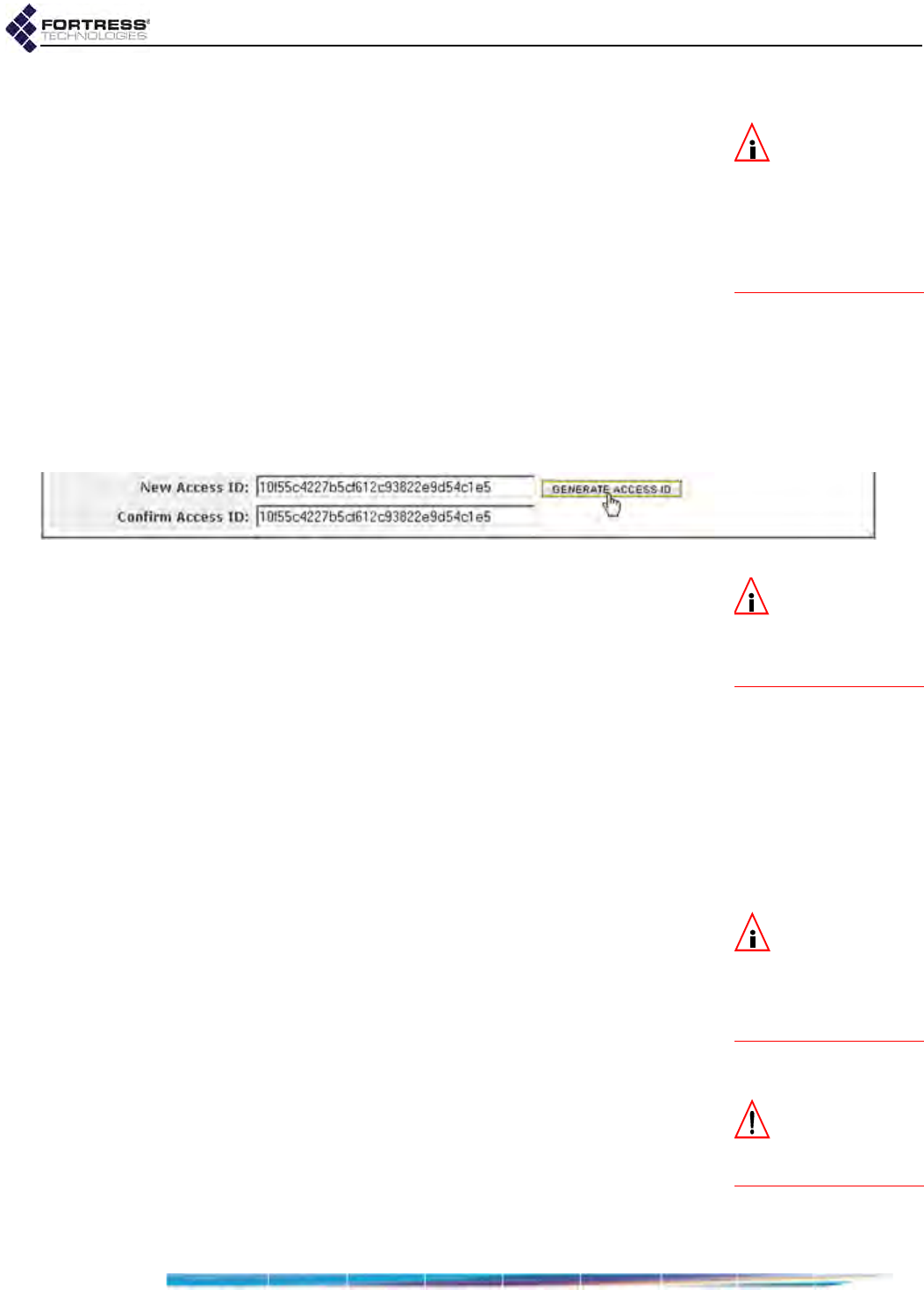
Bridge GUI Guide: Security Configuration
125
4.1.17 Fortress Access ID
NOTE: The default
Access ID is repre-
sented by 16 zeros or
the word, default. Manu-
ally entering either val-
ue returns the Bridge’s
Access ID to its default
setting.
The Access ID provides network authentication for the Fortress
Security System. This 16- or 32-digit hexadecimal ID is
established during installation, after which the same Access ID
must be specified for all of the Bridge’s Secure Clients (and
other connecting Fortress controller devices).
Likewise, if you change the Bridge’s Access ID, you must
subsequently make the same change to all of its Secure
Clients’ Access IDs. For information on setting the Access ID
on Secure Clients, refer to the Fortress Secure Client user
guide.
You can manually enter either a 16-digit or a 32-digit
hexadecimal Access ID of your own composition, or you can
elect to have the Bridge randomly generate an Access ID and
display the result for you to record.
Figure 4.3. Fortress
Access ID
controls, all platforms
NOTE: Secure Cli-
ent versions earli-
er than 3.1 support only
16-digit hexadecimal
Access IDs.
32-digit hexadecimal Access IDs are incompatible with DH-512
key establishment (described in Section 4.1.3). A manually
entered 32-digit Access ID will not be accepted if DH-512 is
selected for key establishment in the Bridge. The length of a
randomly generated Access ID is determined by the key
establishment selections in effect when you click the GENERATE
ACCESS ID button: if DH-512 is selected, a 16-digit hexadecimal
Access ID is generated; if DH-512 is not selected, a 32-digit
hexadecimal Access ID is generated.
Regardless of how you establish the Bridge’s Access ID, you
must make a record of the Access ID at the same time that you
create it. For security purposes, once you have left the screen
on which you establish it, the Access ID can never again be
displayed.
NOTE: A 32-digit
Access ID cannot
be configured when
DH-512 key establish-
ment (Section 4.1.3) is
selected.
To change the Access ID:
1Log on to the Bridge GUI through an Administrator-level
account and select Configure -> Security from the menu on
the left.
2On the Security screen’s Security Settings frame:
If you want to randomly generate the Access ID to be used on
the Bridge-secured network:
CAUTION: The Ac-
cess ID cannot be
displayed after it has
been created.
Click GENERATE ACCESS ID to generate a 16-digit (when
DH-512 key establishment is selected) or a 32-digit
(when DH-512 is not selected) hexadecimal Access ID.
Record the Access ID in a safe place. Once you have
left the page on which it was generated, the Access ID
can never again be displayed.

Bridge GUI Guide: Security Configuration
126
or
If you want to manually enter a 16-digit or a 32-digit
hexadecimal Access ID of your own composition:
In New Access ID and Confirm Access ID, enter the 16-
or 32-digit hexadecimal Access ID to be used by the
Bridge and its Secure Clients.
Record the Access ID in a safe place. Once you have
left the screen on which it was initially established, the
Access ID can never again be displayed.
3Click APPLY in the upper right of the screen (or RESET
screen settings to cancel your changes).
4.2 Internet Protocol Security
NOTE: Fortress’s
IPsec function is
not yet supported on
IPv6 networks.
Fortress Bridges can be configured to secure private
communications over public networks by implementing the
IPsec protocol suite developed by the IETF (Internet
Engineering Task Force) to protect data at the Network Layer
(Layer 3) of the OSI model.
Fortress’s IPsec implementation uses:
ISAKMP (Internet Security Association and Key
Management Protocol) as defined in RFC 2408
NOTE: Fortress de-
vices do not initi-
ate IKE v1 transactions,
but will accept IKE v1
connections from lega-
cy devices.
IKEv2 (Internet Key Exchange version 2) as defined in
RFC 4306
IPsec Tunnel Mode using ESP (Encapsulating Security
Payload) as defined in RFC 4303
Strong standards-based cryptographic algorithm suites
including:
NSA (National Security Agency) Suite B6:
AES-128-GCM, 16B ICV7
AES-256-GCM, 16B ICV
Legacy AES-128-CBC (Cipher Block Chaining)
In IPsec Phase 1, ISAKMP is used to authenticate the initial
Security Association (SA)—via digital signature or pre-shared
key—and to encrypt the control channel over which IKE
messages are exchanged. The Phase 1 IKE SA secures
negotiation of the Phase 2 IPsec SAs over which network traffic
is sent and received, according to the ESP protocol, using the
specified encryption standard(s).
How IPsec is applied to traffic on the Bridge is determined by
the Security Policy Database (SPD) entries configured—per
interface—to apply a specified action to traffic selected by its
source and destination subnets.
Once the function is enabled and configured, the Bridge
functions as an IPsec gateway for the locally connected
6. Refer to Footnote 1 on page 2.
7. Advanced Encryption Standard-Galois/Counter Mode, 16-bit integrity check value
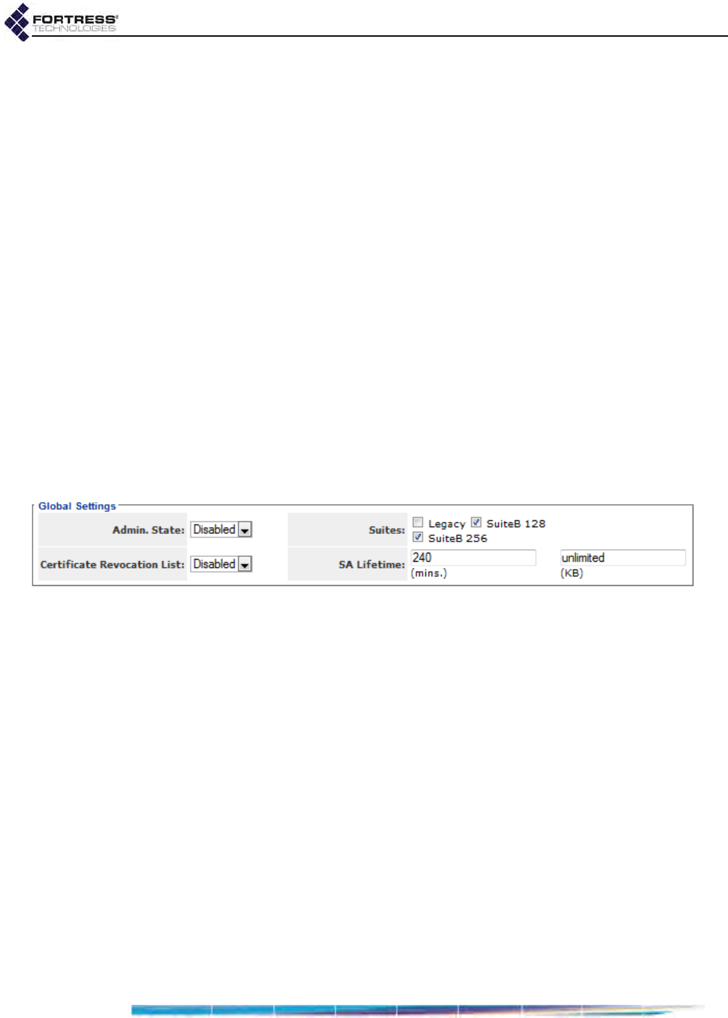
Bridge GUI Guide: Security Configuration
127
devices, using its own IP address as the IPsec peer address
and conducting IKE transactions on behalf of (and
transparently to) the devices it secures.
IPsec can be used alone or in conjunction with the Fortress
Security settings described in Section 4.1.
4.2.1 Global IPsec Settings
IPsec is globally disabled by default. When you enable IPsec,
you must also provide for at least one authentication method
for ISAKMP connections:
For IPsec peers to be authenticated via digital signature
using an X.509 certificate, you must also have specified a
locally stored key pair and certificate to authenticate the
Bridge as an IPsec endpoint. Refer to Section 6.2.1 for
guidance on creating an IPsec key pair.
For IPsec peers to be authenticated by pre-shared keys,
you must specify those keys, per peer (refer to Section
4.2.3, below).
Once IPsec is globally enabled and configured, you must
specify at least one SPD entry (configured to Apply IPsec) on at
least one Bridge interface, before the Bridge can send and
receive IPsec-protected traffic (refer to Section 4.2.2).
Figure 4.4. IPsec
Global Settings
frame, all platforms
Global IPsec settings include:
Admin. State - globally sets the Bridge’s IPsec function to
Enabled or Disabled.
Certificate Revocation List - When the IPsec CRL function is
Disabled, the default, certificates used to authenticate IPsec
peers are not checked against the lists of certificates that
have been revoked by their issuing authorities. When the
IPsec CRL function is Enabled, peer certificate chains are
traced back to a trusted root certificate and each
certificate's serial number is checked against the contents
of the issuing authority’s CRL to verify that none of the
certificates in the chain have been revoked, as described in
RFC 3280.

Bridge GUI Guide: Security Configuration
128
NOTE: Unlike
Suite B Key Estab-
lishment options (Sec-
tion 4.1.3), Suite B IPsec
Cryptographic Algorithm
options are available re-
gardless of whether
Suite B is licensed on the
Bridge (Section 6.3).
Suites - selects the cryptographic algorithm suite(s) that the
Bridge will accept when acting as an IKE responder and will
offer when acting as an IKE initiator.
SuiteB 256 - AES-256-GCM, 16B ICV (default selection)
SuiteB 128 - AES-128-GCM, 16B ICV (default selection)
Legacy - AES-128-CBC
SA Lifetime - specifies a time- and/or data-limited lifespan at
the end of which a new IKE transaction must be negotiated
to establish new IPsec SAs for the connection:
in minutes (mins.) from 1 to 71,582,788 to determine
how long the SA will be used before it expires, or
specify 0 (zero) to impose no time limit.
in kilobytes (KB) from 1 to 4,294,967,295 to determine
how much data will pass on the SA before it expires, or
specify 0 (zero) to impose no data limit.
If both fields are set to positive values, both apply, and
whichever condition occurs first will cause the SA to expire.
The default SA Lifetime is set, in minutes, at 240 (4 hours),
with an unlimited amount of traffic permitted.
CAUTION:
If you
disable IPsec when
the function is in use, all
IKE and IPsec SAs will
be immediately termi-
nated, configured SPD
entries will be disabled,
and IPsec traffic will
cease to be sent or re-
ceived on any interface.
To configure global IPsec settings:
1Log on to the Bridge GUI through an Administrator-level
account and select Configure -> IPsec from the menu on the
left.
2On the IPsec Settings screen’s Global Settings frame, enter
new values for the settings you want to change (described
above).
3Click APPLY in the upper right of the screen (or CANCEL your
changes).
4.2.2 Interface Security Policy Database Entries
When IPsec is globally enabled and configured (refer to
Section 4.2.1), each of the Bridge’s network interfaces can be
associated with up to 100 SPD entries.
An interface with one or more SPD configured for it is enabled
to pass IPsec traffic. An interface with no SPD configured for it
is disabled for IPsec traffic.
Each SPD entry defines the traffic to which it will apply by a
specified local subnet of IP addresses—the source of outbound
traffic and destination of inbound traffic. You can likewise
specify a remote subnet of IP addresses to which an SPD will
apply—defining traffic by its outbound destination/inbound
source—as well as the IP address of the connecting device.

Bridge GUI Guide: Security Configuration
129
How traffic defined by an SPD entry will be handled is
determined by the Action specified in the entry, as shown in
Table 4.2.
Traffic on an interface that has no matching SPD definition will
be handled according to whether any SPD entry has been
configured for that interface:
NOTE: Devices
that implement
the IPsec model are
sometimes referred to as
red/black boxes.
An interface with no SPD entry configured for it permits
packets to pass unprotected by IPsec. Such an interface is
a red interface, in IPsec terms, indicating the unprotected
status of traffic on that interface.
An interface with at least one SPD entry configured for it
drops any packet that does not match (one of) the traffic
selector(s) defined by the SPD entry(-ies) configured for
that interface. In IPsec terms, such an interface is
functioning as a black interface, indicating the secure
status of any traffic passing on it.
SPD entry settings include:
Policy Name - identifies the SPD entry in the Bridge
configuration.
NOTE: A BSS must
be already be pres-
ent on a Bridge radio be-
fore it can be associated
with an SPD entry.
Interface Name and BSS Name - associates the SPD entry
with a particular interface on the Bridge.
The Interface Name dropdown provides a list of the Bridge’s
Ethernet interfaces. The BSS Name dropdown provides a
list of BSSs currently configured on (one of) the Bridge’s
internal radio(s). Use only one of these dropdown lists to
specify only a single Ethernet or wireless interface.
Local Address and Local Mask - defines the traffic to which
the SPD entry will apply by the local subnet of IP addresses
that will comprise the outbound source/inbound destination
of that traffic.
Remote Address and Remote Mask - defines the traffic to
which the SPD entry will apply by the remote subnet of IP
addresses that will comprise the inbound source/outbound
destination of that traffic
Priority - establishes the order in which the policy defined by
the entry will be applied, from 1 to 100, relative to other
configured policies. Priority values must be unique. Policies
with lower Priority numbers take precedence over those
with higher Priority numbers.
Table 4.2. Configurable SPD Entry Actions
action inbound packets outbound packets
Apply
must be IPsec-protected IPsec-encrypt and send as ESP
Bypass
must not be IPsec-protected send unprotected by IPsec
Drop
drop without further processing
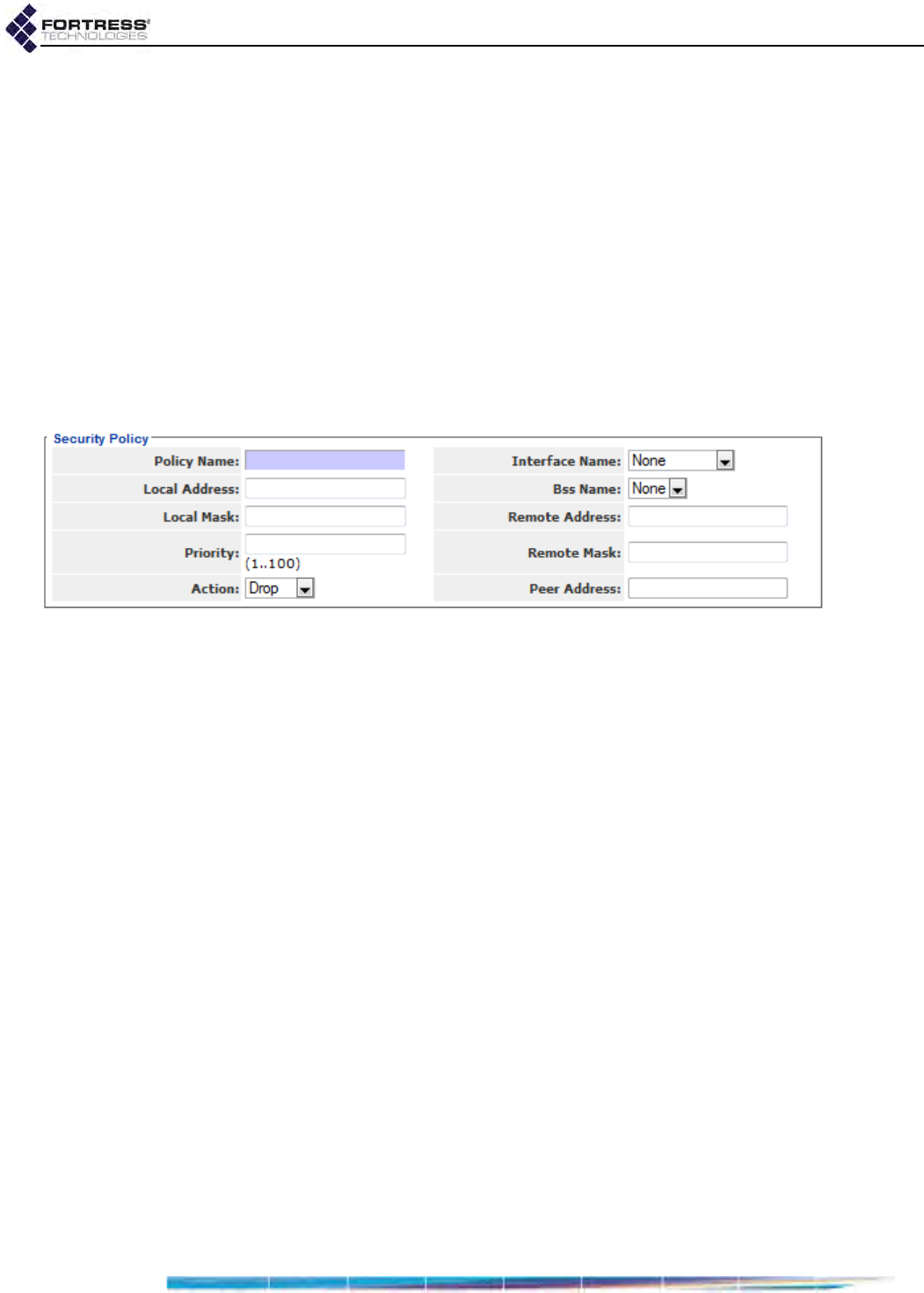
Bridge GUI Guide: Security Configuration
130
Action - determines how packets selected by the local and
remote subnet parameters specified above will be handled:
Drop - drop packets without further processing
(default selection)
Bypass - receive and send only packets unprotected
by IPsec
Apply - receive and send only packets protected
by IPsec
Peer Address - if the Action to be applied by the SPD entry
is Apply, you must identify the IP address of the remote
device to and from which IPsec-protected traffic will be
sent. If the Action is Drop or Bypass, no IPsec peer is
expected for the SPD and you cannot enter an IP address
in this field.
Figure 4.5. IPsec
Security Policy
Database entry frame, all platforms
To add an IPsec SPD entry to a Bridge interface:
1Log on to the Bridge GUI through an Administrator-level
account and select Configure -> IPsec from the menu on the
left.
2In the IPsec Settings screen’s Security Policies frame, click
ADD SPD and, on the resulting screen, enter valid values for
the settings described above.
3Click APPLY in the upper right of the screen (or CANCEL the
addition).
The SPD entries you add are listed in the Security Policies
frame.
To delete IPsec SPD entries:
1Log on to the Bridge GUI through an Administrator-level
account and select Configure -> IPsec from the menu on the
left.
2In the IPsec Settings screen’s Security Policies frame:
If you want to delete a single SPD entry or selected
entries, click to place a checkmark in the box(es)
beside the entry(-ies) you want to eliminate.
or
If you want to delete all SPD entries, click ALL at the top
of the Security Policies list to check all entries.
Click the Security Policies frame’s DELETE SPD button.
Deleted SPD entries are removed from the Security Policies list.
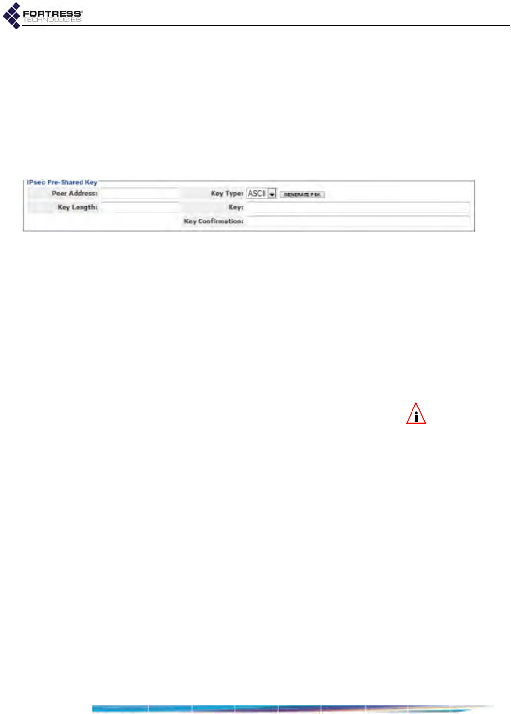
Bridge GUI Guide: Security Configuration
131
4.2.3 IPsec Pre-Shared Keys
As an alternative to using a digital certificate, the identity a
given IPsec peer can be authenticated by a static pre-shared
key (PSK), as configured on both parties to the initial ISAKMP
transaction.
PSKs on the Bridge can be specified as a string of ASCII
characters or a series of hex bytes (hexadecimal pairs).
Alternatively, you can generate a random key, of a specified
length, expressed in hex bytes.
Figure 4.6.
IPsec PSK
settings frame, all platforms
To configure a PSK for an IPsec peer:
1Log on to the Bridge GUI through an Administrator-level
account and select Configure -> IPsec from the menu on the
left.
2In the IPsec Settings screen’s Pre-Shared Keys frame, click
ADD PSK and, on the resulting screen, in Peer Address,
specify the IP address of the IPsec peer to be
authenticated by the PSK.
3On the same screen, establish the key to be used to
authenticate the specified IPsec peer:
NOTE: The Secret
Length parameter
is ignored for manually
entered PSKs.
If you want to specify a key:
In Key Type - use the dropdown to specify whether
the key you enter is an ASCII string or a series of
Hex bytes.
In Key and Key Confirmation - enter a key in the
format you specified above.
or
If you want to automatically generate a random key:
In Key Length - optionally specify the number of
bytes to comprise the key, from 1 to 64. If you omit
this value, the default key length is 32 bytes.
In Key Type - use the dropdown to specify whether
an ASCII string or a series of Hex bytes should be
generated, and click GENERATE PSK.
Record the resulting PSK. You must configure a
matching key on the IPsec peer specified in Step 2.
4Click APPLY in the upper right of the screen (or CANCEL the
addition).
The IP addresses of the IPsec peers for which PSKs are
configured are listed in the Pre-Shared Keys frame.
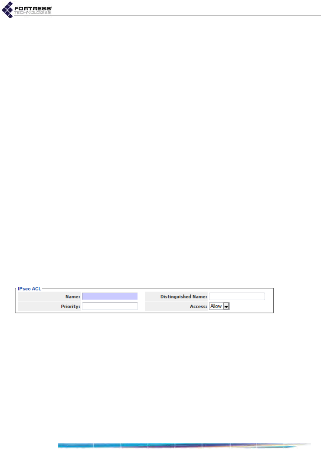
Bridge GUI Guide: Security Configuration
132
To delete IPsec peer PSKs:
1Log on to the Bridge GUI through an Administrator-level
account and select Configure -> IPsec from the menu on the
left.
2In the IPsec Settings screen’s Pre-Shared Keys frame:
If you want to delete the PSK for a single or selected
IPsec peers, click to place a checkmark in the box(es)
beside the IP address(es) of the peer(s) for which you
want to delete the PSK(s).
or
If you want to delete all IPsec peer PSKs, click ALL at
the top of the Pre-Shared Keys list to check all IP
addresses.
Click the Pre-Shared Keys frame’s DELETE PSK button.
The IP addresses of the IPsec peers whose PSKs are deleted
are removed from the Pre-Shared Keys list.
4.2.4 IPsec Access Control List
An additional level of security can be provided in the Bridge’s
IPsec implementation via the IPsec ACL.
The function is enabled when at least one ACL entry is
configured. It is disabled by default: no ACL entries are
present.
When the IPsec access control function is enabled, the Bridge
compares the Distinguished Names (DNs) contained in the
X.509 digital certificates of authenticating IPsec peers against
those recorded in the IPsec ACL. If no match is found, access
is denied. If a match is found, access is allowed or denied
according to the ACL entry’s Access rule.
Figure 4.7.
IPsec ACL
entry frame, all platforms
You can configure up to 100 IPsec ACL entries to be applied in
the specified priority. Settings include:
Name - identifies the ACL entry in the Bridge configuration.
Distinguished Name - specifies the DN pattern against
which those in the X.509 certificates of IPsec peers will be
matched. Each RDN (Relative Distinguished Name) in the
sequence comprising the certificate DN is compared to the
corresponding RDN specified in the IPsec ACL entry. You
can use wildcard characters (*) in the RDNs that comprise
the Distinguished Name specified for an ACL entry.
For example, the DN pattern:
C=US, ST=Florida, O=*

Bridge GUI Guide: Security Configuration
133
matches the DN:
C=US, ST=Florida, O="Fortress Technologies” OU=Engineering
but does not match the DNs:
C=US, ST=Florida, OU=Engineering
C=US, ST=Florida, L=Oldsmar, O="Fortress Technologies”
Priority - establishes the order in which the ACL entry will
be applied, from 1 to 100, relative to other configured ACL
entries. Priority values must be unique. Entries with lower
Priority numbers take precedence over those with higher
Priority numbers.
Access - determines whether the Bridge will Allow (the
default) or Deny access to IPsec peers whose X.509
certificate DNs match the DN pattern of the entry.
To add an IPsec ACL entry:
1Log on to the Bridge GUI through an Administrator-level
account and select Configure -> IPsec from the menu on the
left.
2In the IPsec Settings screen’s IPsec ACLs frame, click ADD
ACL and, on the resulting screen, enter values for the
settings described above.
3Click APPLY in the upper right of the screen (or CANCEL the
addition).
The ACL entries you add are listed in the IPsec ACLs frame.
To delete IPsec ACL entries:
1Log on to the Bridge GUI through an Administrator-level
account and select Configure -> IPsec from the menu on the
left.
2In the IPsec Settings screen’s IPsec ACLs frame:
If you want to delete a single ACL entry or selected
entries, click to place a checkmark in the box(es)
beside the entry(-ies) you want to eliminate.
NOTE: Deleting all
ACL entries dis-
ables the Bridge’s IPsec
ACL function.
or
If you want to delete all ACL entries, click ALL at the top
of the IPsec ACLs list to check all entries.
Click the IPsec ACLs frame’s DELETE ACL button.
Deleted ACL entries are removed from the IPsec ACLs list.
4.3 Authentication Services
The Bridge is equipped with an internal, or local, RADIUS
(Remote Authentication Dial In User Service) server (Section
4.3.2). It can also be configured to use external authentication
servers, both 3rd-party RADIUS servers and those of other
Fortress Bridges to which the current Bridge is connected
(Section 4.3.1).
Bridge GUI Guide: Security Configuration
134
NOTE: If you are
using an external
RADIUS server, config-
ure user timeouts in that
service.
Authentication is enabled on the Bridge when at least one
authentication server is configured and enabled on the Bridge.
You can configure two types of authentication server for the
network, depending on the network configuration:
Fortress Auth. - identifies an authentication service running
internally on a Fortress Bridge (either on the local Bridge or
on a Fortress Bridge external to the current Bridge). A
Bridge’s internal authentication server is always available.
Availability of external Fortress authentication servers
depends on whether other Bridges configured for
authentication are present on the network.
3rd Party RADIUS - identifies a non-Fortress RADIUS server.
The Bridge can be used with most standard RADIUS
servers likely to be present on the network, including:
Microsoft® Internet Authentication Service (IAS)
included in Windows® Server 2003
the open source freeRADIUS version 2.1
CAUTION: Only
the Fortress Auth.
authentication server
type supports both RA-
DIUS user authentica-
tion and Fortress device
authentication. 3rd Par-
ty RADIUS servers do
not support device au-
thentication.
For each of the three possible authentication types (Auth
Types) that you want the Bridge to support, you must specify at
least one authentication server that supports that
authentication type. Auth Types include:
User/Device Authentication - 1) the user name and
password, as supplied by the user logging in and
configured locally or on an authentication server
providing user authentication to the network, and 2) the
unique, hexadecimal Device ID generated for each
Secure Client device and used to authenticate it on a
Fortress-secured network
NOTE: Enabling
802.1X on any
Ethernet port or using
WPA or WPA2 BSS Wi-Fi
Security options that do
not use PSK (Section
3.3.4.14) all require
that
you configure an 802.1X
authentication service on
or for the
Bridge
.
802.1X - supplicant credentials
Admin - the user name and password of an
administrator on the Bridge, as supplied by the
administrator logging in and configured locally or on an
authentication server providing administrative
authentication over the network
Only Fortress RADIUS servers fully support all three types of
authentication. Table 4.3 shows the authentication types
supported by the two possible server types.
In order to use a 3rd -party RADIUS server to authenticate
Bridge administrators, the server must be configured to use
Fortress’s Vendor-Specific Attributes (Fortress-Administrative-
Table 4.3. Supported
Auth. Types
by Configurable Server
Type
Authentication Fortress Auth. 3rd Party RADIUS
User/Device yes user only
802.1X yes yes
Admin yes yes
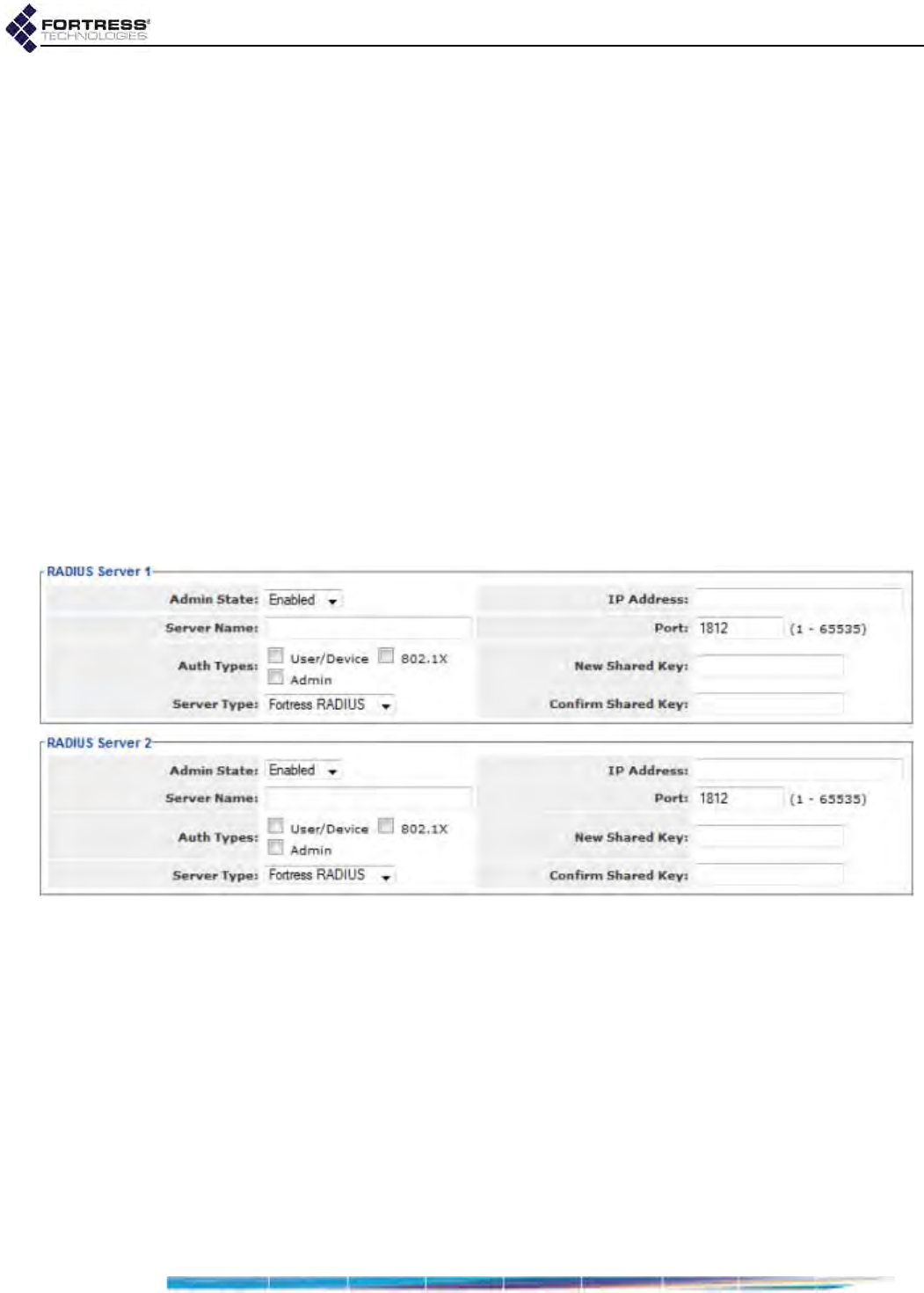
Bridge GUI Guide: Security Configuration
135
Role, Fortress-Password-Expired) and administrators must be
configured on the server. Fortress Vendor-Specific Attributes
are provided in the dictionary.fortress configuration file
included on the Bridge software CD and are available for
download at www.fortresstech.com/support/. Consult your
external RADIUS server documentation for instructions on
configuring the service
You can configure the same authentication server for more
than one supported authentication type.
Even when no authentication server is configured for the
Bridge, you can set global session idle timeouts for connected
Secure Client and host devices connecting to the Bridge
(Section 4.4).
If you are using the Bridge’s internal RADIUS server, you can
set local default timeout settings for authenticating Secure
Client devices and users (Section 4.3.2) that will override the
RADIUS-server-independent Secure Client idle timeout
described above. Individual user and device timeout settings
override the local defaults (Section 4.3.3).
Figure 4.8. Simple View, external
RADIUS Server
frames, all platforms
The Bridge can use up to four authentication servers at a time,
although in Simple View you can configure only two. None is
configured by default (as indicated by the blank IP Address and
Shared Key fields in Simple View and the empty Server List in
Advanced View).
More than one authentication server can be configured on the
Bridge for purposes of redundancy. For a given authentication
type, however, only the relevant server with the first priority will
be used to check authentication credentials. The success or
failure of a given authentication attempt is therefore determined
solely by the active authentication server for that authentication
type. That is, credentials are authenticated or failed by the

Bridge GUI Guide: Security Configuration
136
relevant server and failed credentials are not forwarded to any
other server.
If the server with first priority for a given authentication type
becomes unavailable, the next server in the priority sequence
that has also been configured to support that authentication
type will be used.
In Advanced View, where you can configure up to four RADIUS
servers, you can specify the priority number of each. In Simple
View, RADIUS Server 1 has priority over RADIUS Server 2.
Advanced View also allows you to configure the maximum
number of allowable authentication attempts and the retry
interval for each server. These settings apply globally to all
users and (if applicable) devices authenticated by that server.
4.3.1 Authentication Server Settings
External authentication servers can be added and reconfigured
only through the settings described below.
Once the internal authentication server has been added to the
Bridge configuration with the settings on the Local Server tab of
the RADIUS Settings screen, you can reconfigure some
aspects of its operation from its entry on the Server List or, in
Simple View, in the corresponding RADIUS Server frame.
However, the internal server can be added, and complete
settings for it can be accessed, only on the Local Server tab, as
described in Section 4.3.2.
4.3.1.1 Authentication Server State, Name, and IP Address
NOTE: The Server
Name and IP Ad-
dress of the internal RA-
DIUS server (Local Auth
Sever and 127.0.0.1, re-
spectively) are internal-
ly set and cannot be
changed.
The Admin State setting determines whether the Bridge
forwards authentication requests of the applicable type(s) to
the server (Enabled) or not (Disabled).
You must specify a unique Server Name to identify an external
server in the Bridge configuration. You cannot edit the Server
Name once it is established.
You must specify the network IP Address of an external
authentication server in order to add it to the Bridge
configuration.
4.3.1.2 Authentication Server Port and Shared Key
The Port setting configures the UDP port to be used to
communicate with the authentication server. The default
authentication server port is 1812, as assigned by the IANA
(Internet Assigned Numbers Authority) for RADIUS server
authentication.
NOTE: The server
key you enter here
should already be pres-
ent in the authentication
service configuration.
Use the New Shared Key and Confirm Shared Key fields to
establish the key used to authenticate the Bridge on the
external authentication server.
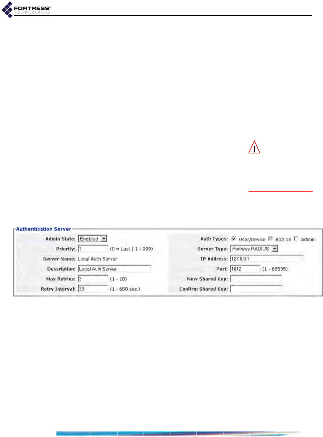
Bridge GUI Guide: Security Configuration
137
4.3.1.3 Server Type and Authentication Types
The Server Type setting identifies the type of authentication
service running on the configured server, while Auth Types
selections specify which type(s) of authentication credentials
will be sent to the server. Refer to the description at the
beginning of this section (Section 4.3) on page 133 for more
detail.
4.3.1.4 Authentication Server Priority
In configurations with multiple authentication servers, Priority
establishes the server’s position in the order of redundant
servers for the specified authentication type(s). Numerical
values between 1 and 999 are accepted. The default value,
Last, places the server last on the server priority list.
NOTE: You must
enable the Bridge’s
internal authentication
server in order to enable
local authentication on
the Bridge (refer to Sec-
tion 4.3.2).
4.3.1.5 Authentication Server Max Retries and Retry Interval
The Max Retries setting determines how many times the Bridge
will attempt to connect to the server before assuming it is
unavailable and going on to the next relevant server on the
priority list. You can configure 1 to 10 maximum connection
attempts; the default is 3. Max Retries is available in only
Advanced View.
Retry Interval specifies how long the Bridge will wait between
connection retries (above). Retry Interval is available only in
Advanced View.
Figure 4.9. Advanced View,
Authentication Server
frame, all platforms
4.3.1.6 Configuring Authentication Servers
You can add external servers to the Bridge configuration
through the settings described in sections 4.3.1.1 through
4.3.1.5, and you can reconfigure these settings for any
RADIUS server already in the Bridge configuration. You can
add the internal server to the configuration and access all of
the settings associated with it only on the Local Server tab, in
Advanced View (refer to Section 4.3.2).
Table 4.4 shows which of these settings can be configured in
each Bridge GUI view.

Bridge GUI Guide: Security Configuration
138
To configure a RADIUS server in Simple View:
1Log on to the Bridge GUI through an Administrator-level
account and select Configure -> RADIUS Settings from the
menu on the left.
2On the RADIUS Settings screen, enter new values for the
RADIUS Server 1 and/or RADIUS Server 2 settings you want
to change (described above).
3Click APPLY in the upper right of the screen (or RESET
screen settings to cancel your changes).
To configure a RADIUS server in Advanced View:
1Log on to the Bridge GUI through an Administrator-level
account and select ADVANCED VIEW in the upper right corner
of the page, then Configure -> RADIUS Settings from the
menu on the left.
2On the RADIUS Settings screen:
If you want to add a new server, click the NEW SERVER
button in the upper left of the screen.
or
If you want to edit an existing server, click the EDIT
button to the left of its entry on the Authentication
Servers list.
3In the RADIUS Settings screen’s Authentication Server
frame, enter new values for the settings you want to
change (described above).
4Click APPLY in the upper right of the screen (or CANCEL your
changes.)
4.3.2 The Local Authentication Server
Enable and configure the Bridge’s internal RADIUS server and
local user and device authentication, in Advanced View, on the
Local Server tab of the RADIUS Settings screen.
4.3.2.1 Local Authentication Server State
The Administrative State setting turns the local authentication
service on (Enabled) and off (Disabled, the default).
Table 4.4. External Authentication Server Settings
Simple & Advanced Views Advanced View Only
Admin. State Priority
IP Address Max Retries
Server Name Retry Interval
Port
Auth Types
Server Type
New/Confirmed Shared Key

Bridge GUI Guide: Security Configuration
139
4.3.2.2 Local Authentication Server Port and Shared Key
The Port setting configures the port to be used to communicate
with the local authentication server. The default authentication
server port is 1812, as assigned by the IANA (Internet
Assigned Numbers Authority) for RADIUS server
authentication.
Use the New Shared Key and Confirm Shared Key fields to
establish the shared key for the Bridge’s internal authentication
server. The key must be 1–16 (inclusive) characters in length,
and it can contain any printable character. The same key must
be configured on other Fortress controller devices when they
are configured to use the current Bridge’s authentication
server.
4.3.2.3 Local Authentication Server Priority
In configurations with multiple authentication servers, Priority
establishes the server’s position in the order of redundant
servers for the specified authentication type(s). Numerical
values between 1 and 999 are accepted. The default value,
Last, places the server last on the server priority list.
4.3.2.4 Local Authentication Server
Max Retries and Retry Interval
The Max Server Retries setting determines the maximum
number of unsuccessful local authentication attempts a user or
device is allowed before being locked out. You can specify
whole numbers between 1 and 10; the default is 3.
A devices that exceeds the maximum allowable retry attempts
to authenticate on the Bridge is locked out until the device’s
individual Auth State Mode is set to Allow First. Such a device is
locked out on every Bridge in a network, and you must change
the device’s Auth State Mode on every Bridge that handles
traffic from the device.
Users who exceed the maximum allowable retry attempts to
log on to the Bridge-secured network are locked out until you
reset their sessions. On a network of Bridges, you must reset
the session on each Bridge that passes traffic for the device.
Retry Interval specifies how long the Bridge requires a user or
device to wait between connection retries.
4.3.2.5 Local Authentication Server
Default Idle and Session Timeouts
The Default Idle Timeout setting determines the amount of time
a device can be idle on the network before the current session
is ended and the associated Device ID and/or user credentials
must be reauthenticated and keys renegotiated before the
connection can be re-established. If local user authentication is
in effect for the device and Permit cached authentication
credentials is globally Disabled on Configuration -> Security

Bridge GUI Guide: Security Configuration
140
(Section 4.1.13), the user will be prompted to re-enter a valid
username and password.
Set Default Idle Timeout in minutes, between 1 and 720. The
default is 30 minutes.
The Default Session Timeout - setting determines the amount of
time a device can be present on the network before the current
session is ended and the associated Device ID and/or user
credentials must be reauthenticated and keys renegotiated
before the connection can be re-established. If local user
authentication is in effect for the device, the user will be
prompted to re-enter a valid username and password.
Set Default Session Timeout in minutes, between 1 and 200.
The default is 30 minutes.
4.3.2.6 Local Authentication Server
Global Device, User and Administrator Settings
The Default Device State setting globally determines the default
connection state of devices auto-populating the device
authentication screen and of devices with an individual Auth
State Mode setting of Defer (the default, Section 4.3.3.2):
NOTE:
Individual
device authentica-
tion settings for devices
already present on the
Bridge
’s
Device Authen-
tication
tab (whether
you added them manu-
ally or edited their en-
tries) override the global
Default Device State
set-
ting on the local authen-
tication server.
Allow - the device will be allowed to connect (provided its
individual Auth State Mode is Allow First or Defer and a
compatible Key Length has been specified for the device).
Pending - (the default) the connection requires
administrator action: explicitly changing the device’s
individual Auth State Mode to Allow First (or you can
explicitly Deny All attempted key exchanges for a device),
as described on page 147.
Deny - the device is not allowed on the network (provided it
is not already present on the Device Authentication tab with
an individual Auth State Mode of Allow First).
Whether device authentication is enabled and, if so, whether
devices populating the device authentication database have
user authentication enabled or disabled by default is
determined by Authentication Method:
User auth only - disables device authentication on the
Bridge.
Device auth with user auth by default - enables device
authentication on the Bridge and enables user
authentication by default for new devices auto-populating
the Device Authentication tab on Local Authentication.
Device auth without user auth by default - enables device
authentication on the Bridge and disables user
authentication by default for new devices.
The Administrator Authentication setting enables support for
administrator authentication (Enabled) or disables it (Disabled,
the default). Refer to Section 2.2.1.6 for more detail.

Bridge GUI Guide: Security Configuration
141
4.3.2.7 Local 802.1X Authentication Settings
The Bridge’s internal RADIUS server can be configured to
authenticate 802.1X supplicant credentials using two possible
EAP (Extensible Authentication Protocol) types.
NOTE:
EAP-TLS
provides a signifi-
cantly higher level of se-
curity than EAP-MD5.
EAP-MD5 verifies an MD5 (Message-Digest algorithm 5) hash
of each user’s password, which requires a user’s credentials to
be present in the Bridge’s local user authentication service
before the local 802.1X service can authenticate that user.
Refer to Section 4.3.3.1 for guidance.
In order to use EAP-TLS (EAP with Transport Layer Security)
public key cryptography authentication, you must import a valid
EAP-TLS digital certificate for the local service and the root CA
(Certificate Authority) certificate that signs the local server
certificate. You must also import any root CA certificate(s) used
to sign supplicant certificates, so that the local server can verify
their authenticity. Refer to Section 6.2 for guidance. In addition,
as noted below, three local server configuration settings apply
only when EAP-TLS is selected for EAP Protocols.
802.1X Authentication - turns the service on (Enabled) and
off (Disabled, the default).
CRL Check - for EAP-TLS only, determines whether
certificates used to authenticate 802.1X supplicants are
checked against the lists of certificates that have been
revoked by their issuing authorities. CRL Check is Disabled
by default. When the function is Enabled, supplicant
certificate chains are traced back to a trusted root
certificate and each certificate's serial number is checked
against the contents of the issuing authority’s CRL to verify
that none of the certificates in the chain have been
revoked, as described in RFC 3280. CRL Check does not
apply to EAP-MD5 authentication.
Strict Check - for EAP-TLS only, controls strict checking of
key usage and extended key usage extensions in the
authentication server certificate. Strict Check is Enabled by
default; you can turn it off by selecting Disabled. Strict Check
does not apply to EAP-MD5 authentication.
TLS Cipher - for EAP-TLS only, specifies the list of
supported cipher suites, or sets of encryption and integrity
algorithms, that the 802.1X service will accept:
All - the default, supports both Legacy and Suite B cipher
suites (below)
Legacy - supports Diffie-Hellman with RSA keys
(DHE-RSA-AES128-SHA and DHE-RSA-AES256-SHA)
Suite B - supports Diffie-Hellman with ECC keys
(ECDHE-ECDSA-AES128-SHA and ECDHE-ECDSA-
AES256-SHA)
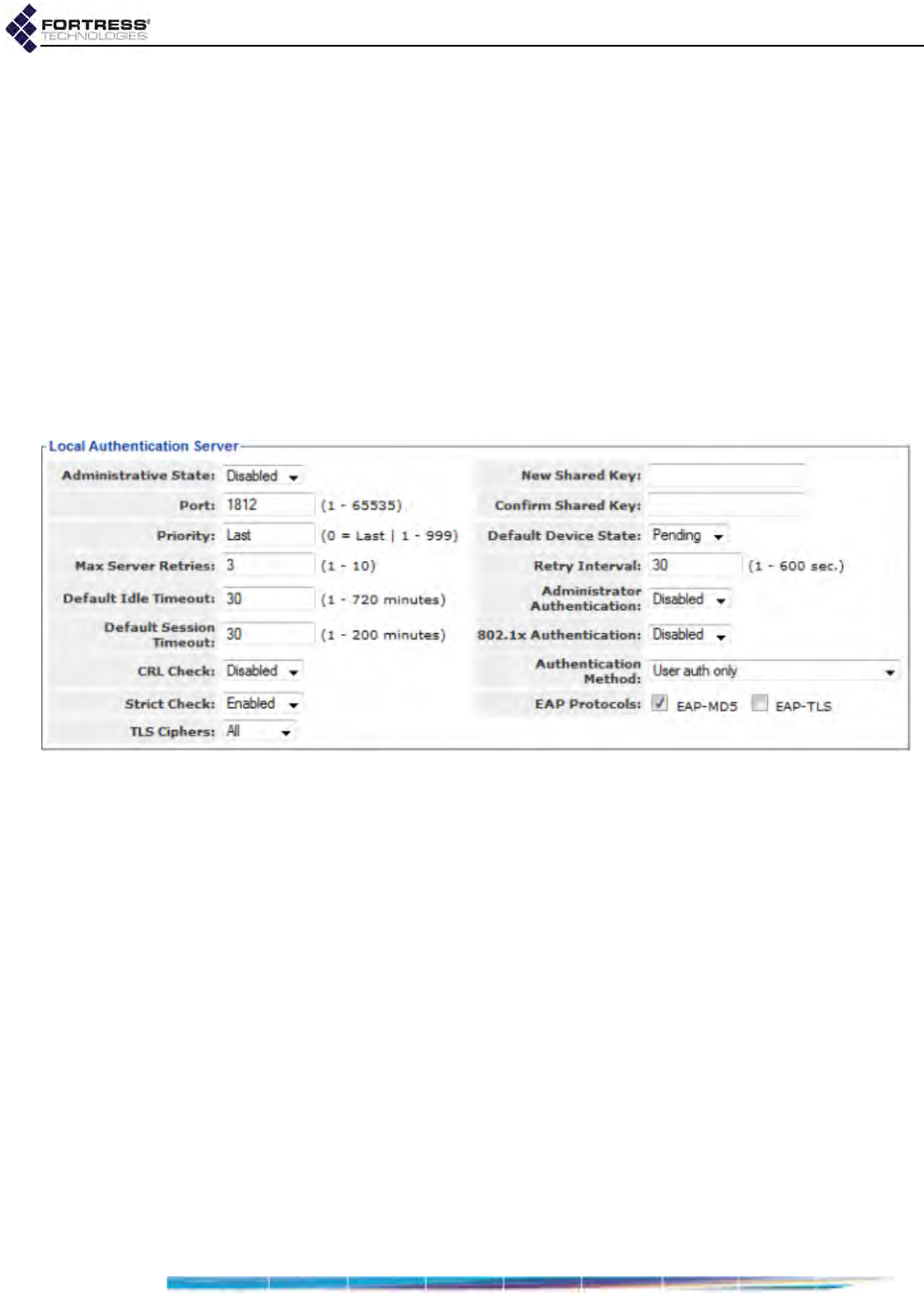
Bridge GUI Guide: Security Configuration
142
In EAP-TLS, the authentication server selects the cipher
suite to use from the list of supported suites sent by the
client device (or rejects the authentication request if none of
the proposed suites are acceptable). TLS Cipher does not
apply to EAP-MD5 authentication.
EAP Protocols - specifies the EAP type(s) the Bridge can
use to authenticate 802.1X supplicant credentials:
EAP-MD5 - (default selection) permits the Bridge to
authenticate a supplicant using an MD5 hash of the
user’s password.
EAP-TLS - when there is a valid EAP-TLS certificate in
the Bridge’s local certificate store (refer to Section 6.2),
permits the Bridge to authenticate a supplicant using
public key cryptography.
Figure 4.10. Advanced View
Local Authentication Server
tab, all platforms
4.3.2.8 Configuring the Local RADIUS Server
You can configure local authentication only in Advanced View.
1Log on to the Bridge GUI through an Administrator-level
account and select ADVANCED VIEW in the upper right corner
of the page, then Configure -> RADIUS Settings from the
menu on the left.
2On the RADIUS Settings screen, click the Local Server tab.
3In the Local Authentication Server frame, enter new values
for the settings you want to configure (described above).
4Click APPLY in the upper right of the screen (or RESET
screen settings to cancel your changes).

Bridge GUI Guide: Security Configuration
143
NOTE:
When using
an external authen-
tication server, user and
(when applicable) device
authentication settings
are configured in the ex-
ternal application.
4.3.3 Local User and Device Authentication
You can configure user and device authentication settings even
when the Bridge’s local authentication is disabled (the default).
The settings will only be applied when the local RADIUS server
is enabled (refer to Section 4.3.2).
4.3.3.1 Local User Authentication Accounts
Locally authenticating users are displayed on the User Entries
list on Configure -> RADIUS Settings -> Local Server.
You cannot disable local user authentication, per se, except by
disabling local authentication entirely. There is, however, no
requirement that you configure local users.
The users for whom you create accounts can fall into one of
two categories:
Secure Client users - are running the Fortress Secure
Client on their connecting devices. They use the Bridge’s
local user authentication service to log on to the Bridge-
secured network. Secure Client users pass only encrypted
traffic on the Bridge’s encrypted interfaces.
Administrative users - use the Bridge’s local user
authentication service to log on to the management
interface of another Fortress Bridge on the network (or of
the local Bridge), when the administrative Authentication
Method on that Bridge is set to RADIUS. Administrative
users pass only encrypted traffic on the Bridge’s encrypted
interfaces.
When an administrative user logs on to the Bridge through
a local or remote Fortress user authentication database (as
configured on the relevant Local Server screen), a Learned
administrative account is created for that user in the
administrator authentication database. You can optionally
convert a Learned account to a local administrative account
that can be used if the original user authentication service
becomes unavailable (refer to Section 2.2.2.8).
One can optionally convert the learned account(s) to local
account(s) that can be used when external admin auth is
disabled.
Default User Authentication Settings
While idle timeout and session timeout settings can be
individually configured for each user, the default values for
these settings are determined by the Default Idle Timeout and
Default Session Timeout values configured on the local RADIUS
server (refer to Section 4.3.2).
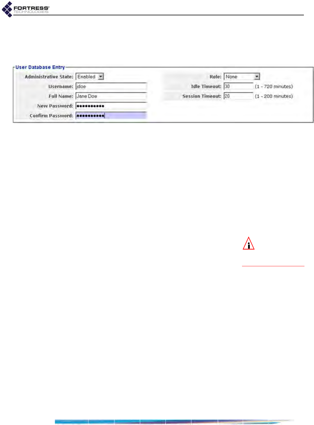
Bridge GUI Guide: Security Configuration
144
Individual User Authentication Settings
User authentication on the Fortress Bridge requires the usual
settings to identify, track and manage access for each user on
the Bridge-secured network.
Figure 4.11. Advanced View
User Database Entry
frame, all platforms
Administrative State - determines whether user access to
the account is Enabled (the default) or Disabled.
Username - identifies the user on the network—from 1 to 16
alphanumeric characters—required.
Full Name - associates the person, by name, with his/her
user account—up to 64 alphanumeric characters, including
spaces, dashes, dots and underscores—optional.
New/Confirm Password - establishes the credentials the
user must key in to access his/her user account—must
comply with the password requirements configured in
Configure -> Security -> Logon Settings (Section 2.2.1.8)—
required.
NOTE:
Adminis-
trative roles are
described in
Section
2.2.2.3.
Role - Determines whether the user is a Secure Client user
permitted access to only the Bridge-secured network
(None) or an administrator permitted access to both the
network and to the management interface of a remote or
local Bridge—at the specified level of privileges (Log Viewer,
Maintenance, or Administrator).
Idle Timeout - sets the amount of time the user’s device can
be idle on the network before it must renegotiate keys with
the Bridge.
Idle Timeout is set in minutes, between 1 and 720. If you
enabled Local Authentication while leaving the local
authentication server’s Default Idle Timeout setting at its
default, the Idle Timeout value in the User Authentication
Setting frame will be 30 minutes.
Session Timeout - sets the amount of time the user’s device
can be present on the network before the current session is
ended and he/she must log back in to re-establish the
connection.
Session Timeout is set in minutes, between 1 and 200. If
you enabled Local Authentication while leaving the local
authentication server’s Default Session Timeout setting at its
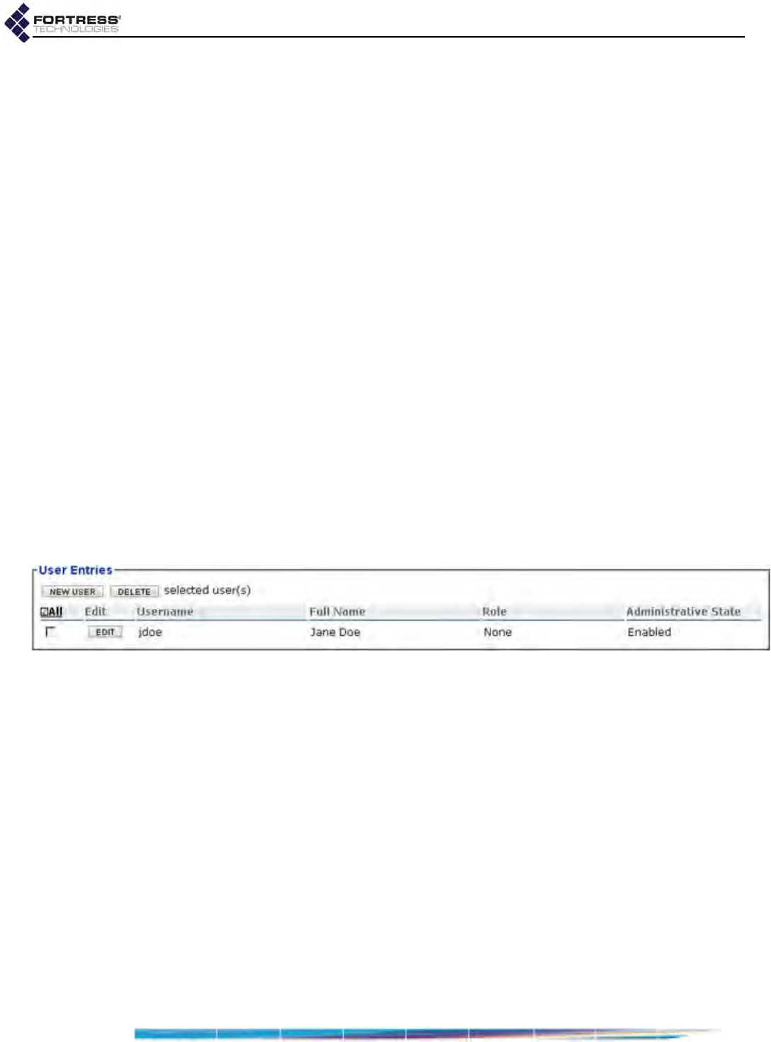
Bridge GUI Guide: Security Configuration
145
default, the Session Timeout value in the User Authentication
Setting frame will be 20 minutes.
You can add and edit locally authenticated users only in
Advanced View.
To configure locally authenticated user accounts:
An existing account’s Username cannot be changed, but you
can edit any other value associated with a user account
1Log on to the Bridge GUI through an Administrator-level
account and select ADVANCED VIEW in the upper right corner
of the page, then Configure -> RADIUS Settings from the
menu on the left.
2On the RADIUS Settings screen, click the Local Server tab.
3In the User Entries frame:
If you are adding a user, click NEW USER and enter valid
values (described above) into the User Database Entry
frame.
or
If are editing an existing account, click the EDIT button
for the account you want to reconfigure and enter new
values for the settings you want to change.
4Click APPLY in the upper right of the screen (or CANCEL the
addition).
Newly created accounts are added to the User Entries list.
Figure 4.12. Advanced View
User Entries
frame, all platforms
To delete local user accounts:
You can delete a single user account, selected accounts, or all
user accounts from the Bridge’s internal RADIUS server.
1Log on to the Bridge GUI through an Administrator-level
account and select ADVANCED VIEW in the upper right corner
of the page, then Configure -> RADIUS Settings from the
menu on the left.
2On the RADIUS Settings screen, click the Local Server tab.
3In the User Entries frame:
If you want to delete a single user account or selected
accounts, click to place a checkmark in the box(es)
beside the account(s) you want to eliminate.
or
If you want to delete all local user accounts, click ALL at
the top of the User Entries list to check all accounts.

Bridge GUI Guide: Security Configuration
146
Click the User Entries frame’s DELETE button.
4Click OK in the confirmation dialog.
Deleted accounts are removed from the User Entries list.
4.3.3.2 Local Device Authentication
NOTE:
Device au-
thentication is sup-
ported only by the
authentication servers
internal to Fortress con-
troller devices; 3rd-par-
ty RADIUS servers do
not support device au-
thentication.
Fortress’s device authentication assigns each Fortress device,
including those running the Fortress Secure Client, a unique
Device ID subsequently used to authenticate the device for
access to the Fortress-secured network.
The Bridge’s native device authentication settings apply only to
devices authenticating through the Bridge’s internal
authentication server.
When device authentication is enabled, the Bridge detects
devices attempting to access the Bridge’s encrypted zone and
lists them on Configure -> RADIUS Settings -> Local Server, in
the Device Entries frame.
You can also manually add devices to the Bridge’s Device
Entries list. In order to add a device manually, you must specify
its MAC address and Fortress-generated Device ID.
Default Device Authentication Settings
As devices auto-populate the Device Entries list., they are
permitted or denied immediate access to the network based on
the Default Device State setting on the (Configure -> RADIUS)
Local Server tab:
Allow - devices will be allowed to connect by default.
Pending - (the default) connections require an administrator
to change individual device authentication settings to Allow.
Deny - devices are not allowed on the network by default.
You can also configure whether user authentication is enabled
or disabled by default for auto-populating devices.
All Local Authentication Server settings are described in Section
4.3.2).
To enable device authentication and configure defaults:
1Log on to the Bridge GUI through an Administrator-level
account and select ADVANCED VIEW in the upper right corner
of the page, then Configure -> RADIUS Settings from the
menu on the left.
2On the RADIUS Settings screen, click the Local Server tab.
3In the Local Authentication Server frame:
Verify that Administrative State is Enabled and that Port
and Shared Key are correctly configured (Section
4.3.2).
From the Default Device State dropdown choose a
default state (described above) for auto-populating
devices.

Bridge GUI Guide: Security Configuration
147
In Authentication Method, simultaneously enable device
authentication and configure the default user
authentication setting, by selecting one of:
Device auth with user auth by default - enables user
authentication for new devices by default.
Device auth without user auth by default - disables
user authentication for new devices by default.
4Click APPLY in the upper right of the screen (or RESET
screen settings to cancel your changes).
Connecting devices will auto-populate the Device Entries list
with the defaults you configured.
Individual Device Authentication Settings
When device authentication is enabled (above), connecting
devices auto-populate the Bridge’s Device Entries list, and any
manually created device authentication accounts on the Bridge
are applied to the devices they specify.
NOTE:
The Device
ID of the current
Bridge is shown on
Configure -> Adminis-
tration, in the System
Info frame at the top of
the screen.
The Fortress Bridge tracks and manages access for devices on
the Fortress-secured network through two identifiers: the
device’s MAC address and its Fortress-generated Device ID.
When a device auto-populates the Device Entries list, these
values are detected and entered for the device. When you
manually add a device, you must specify its MAC address and
Device ID. Consult the relevant Fortress documentation for the
device you are adding for information on determining its
Fortress Device ID.
The values and settings that configure individual device
authentication accounts include:
Administrative State - Determines whether the device is
Enabled (the default) or Disabled for network access.
Device ID - a unique, 16-digit hexadecimal identifier
generated for the device and used to authenticate it on the
network
Once a Fortress Device ID has been generated for a
device, it is not user configurable. If you are manually
adding a device, you must specify its valid, Fortress Device
ID. Once established (manually or automatically), the
Device ID cannot be changed.
MAC Address - the device’s MAC address
If you are manually adding a device, you must specify its
MAC address. Once established (manually or
automatically), the MAC address cannot be changed.
Common Name - accepts up to 64 alphanumeric characters
by which you can identify the device.
If a device has a hostname associated with it (the
hostname of a laptop running the Fortress Secure Client,

Bridge GUI Guide: Security Configuration
148
for instance), that hostname is included for the device when
it is first added to the DEVICE AUTHENTICATION screen. If no
hostname is associated with the device, it will be added
without one. You can edit an existing hostname or add one
for a device that has no hostname.
User Auth - configures whether the Bridge will require the
device’s user to authenticate before allowing the device to
connect to the encrypted zone (Enabled) or allow the device
access without user authentication (Disabled).
Auth State Mode - configures the initial state of the device’s
connection to the encrypted zone:
Allow First - the device will be allowed to connect using
the first key establishment method it attempts to use.
Once the device is connected the Bridge will
automatically detect any other key establishment
methods the connecting device supports, and you can
specify those you wish to allow the device to use for
subsequent connections to the network. If you want the
device to be able to use a supported key establishment
method other than that used for the initial connection,
you must manually enable it for the device.
Deny All - prevents all access to the network; all the
device’s attempts to exchange keys will be denied.
Defer - whether the device is allowed to connect
depends upon the local authentication server’s Default
Device State setting (Section 4.3.2).
Authed Keys - after a device has been added to the Bridge’s
device authentication database and allowed to connect,
you can specify the key establishment method(s) the
device will be allowed to use for subsequent connections.
Available options are limited to the key establishment
method(s) the device has previously used to try to connect.
No Authed Keys are selected by default
You can add and edit locally authenticated Secure Client
devices only in Advanced View.
Figure 4.13. Advanced View
Device Database Entry
frame, all platforms
To configure locally authenticated
Secure Client device accounts:
1Log on to the Bridge GUI through an Administrator-level
account and select ADVANCED VIEW in the upper right corner
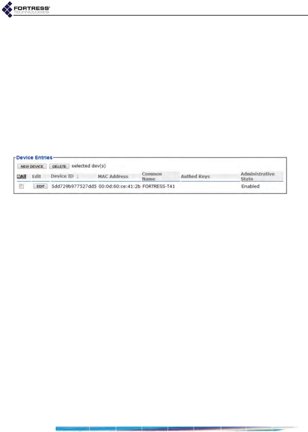
Bridge GUI Guide: Security Configuration
149
of the page, then Configure -> RADIUS Settings from the
menu on the left.
2On the RADIUS Settings screen, click the Local Server tab.
3In the Device Entries frame:
If you are adding a device, click NEW DEVICE and enter
valid values (described above) into the Device Database
Entry frame.
or
If you are editing an existing account, click the EDIT
button for the account you want to reconfigure and
enter new values for the settings you want to change.
4Click APPLY in the upper right of the screen (or CANCEL the
addition).
Newly created accounts are added to the Device Entries list.
Figure 4.14. Advanced View
Device Entries
frame, all platforms
To delete Secure Client device accounts:
You can delete a single device account, selected accounts, or
all device accounts from the Bridge’s internal RADIUS server.
1Log on to the Bridge GUI through an Administrator-level
account and select ADVANCED VIEW in the upper right corner
of the page, then Configure -> RADIUS Settings from the
menu on the left.
2On the RADIUS Settings screen, click the Local Server tab.
3In the Device Entries frame:
If you want to delete a single device account or selected
accounts, click to place a checkmark in the box(es)
beside the account(s) you want to eliminate.
or
If you want to delete all local device accounts, click ALL
at the top of the Device Entries list to checkmark all
accounts.
Click the Device Entries frame’s DELETE button.
4Click OK in the confirmation dialog.
Deleted accounts are removed from the Device Entries list.
4.4 Local Session and Idle Timeouts
When their connections to the Bridge have not passed traffic
for a specified number of seconds, devices are cleared from
the Bridge’s database of currently connected devices. When a

Bridge GUI Guide: Security Configuration
150
device’s session is idle timed out by the Bridge in this way, the
device must re-establish its connection; if it is re-accessing an
encrypted zone it must also reauthenticate.
Idle timeouts can be configured for two types of devices:
Secure Client devices - are the devices running the Fortress
Secure Client to connect to the Bridge’s encrypted zone.
Host devices - are devices in the Bridge’s clear zone.
Host idle timeouts can be set in only one place in the Bridge
GUI, only in Advanced View, on Configure -> Security ->
Security Settings -> Host Idle Timeout (refer to Section 4.1.15).
The Bridge GUI provides more than one configuration field for
Secure Client idle timeouts, to accommodate different
authentication scenarios and administrative options:
NOTE:
Idle timeout
settings for net-
work users’ connecting
devices are distinct from
the globally configured
session idle timeout for
administrators (Section
2.2.1.4).
Configure -> Security -> Security Settings -> Client Idle
Timeout allows you to configure global and individual
Secure Client idle timeouts when local authentication is not
enabled (refer to Section 4.1.15).
Configure -> RADIUS Settings -> Local Server-> Default Idle
Timeout globally determines the default Secure Client
timeout on the Bridge’s local authentication server. When
local authentication is enabled, this setting overrides the
timeout configured on the Security screen (refer to Section
4.3.2).
Configure -> RADIUS Settings -> Local Server-> NEW USER/
EDIT -> Idle Timeout determines the individual Secure
Client’s idle timeout on the Bridge’s local authentication
server. This setting overrides the default user timeout
setting (refer to Section 4.3.3).
In addition, you can set global and individual session timeouts
for locally authenticated users on the second and third screens
described above.
When FastPath Mesh is licensed and enabled, global idle
timeout values for all types of devices are controlled by
software, rather than by configured (or default) global values.
Individual user timeout settings, however, continue to override
global values, as described.
4.5 ACLs and Cleartext Devices
The first Access Control List (ACL) on Configure -> Access
Control, IP Access Whitelist, applies exclusively to
administrative connections to the Bridge’s management
interface and is covered in Section 2.2.3 with the other
administrative access configuration settings.
There is also an ACL associated with the Bridge’s IPsec
function, which is covered in Section 4.2.4 with the other IPsec
configuration settings.
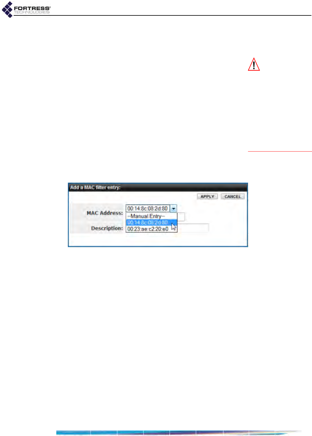
Bridge GUI Guide: Security Configuration
151
The remaining access Access Control functions are covered
below. These prevent, or define limits for, overall network
access, whether by administrators or users.
CAUTION: If you
ignore the relevant
warning, you can block
all network access by
having the MAC Access
Whitelist Enabled when
there are no MAC ad-
dresses listed. Access
can be restored only by
reconfiguring the func-
tion via a direct physical
connection to the
Bridge’s Console port.
4.5.1 MAC Address Access Control
The Bridge allows you to create and maintain an ACL of MAC
(Media Access Control) addresses permitted to access the
Bridge-secured network.
When the MAC Access Whitelist is Enabled, only those MAC
addresses present on the list will be permitted to access the
Bridge-secured network.
To control network access by specified MAC addresses:
1Log on to the Bridge GUI through an Administrator-level
account and select ADVANCED VIEW in the upper right corner
of the page, then Configure -> Access Control from the
menu on the left.
2In the resulting screen’s MAC Access Whitelist frame, click
NEW MAC.
Figure 4.15. Advanced View
Add a MAC filter entry
dialog, all platforms
3In the resulting Add a MAC Filter Entry dialog, select your
current MAC address from the dropdown list above the
MAC Address field (or manually enter the address) and
optionally enter a Description for the entry. Then click
APPLY.
4Repeat steps 2 and 3 for any additional MAC addresses
from which you want to permit network access.
Only MAC addresses of devices currently connected to the
network will be present in the dropdown list. To add a
device that is not currently connected, you must leave the
dropdown at its default, Manual Entry, and manually enter its
MAC address.

Bridge GUI Guide: Security Configuration
152
Figure 4.16. Advanced View
MAC Access Whitelist
frame, all platforms
CAUTION:
If your
current MAC ad-
dress is not on the
MAC
Access Whitelist
when
you
Enable
it or you de-
lete your address when
the list is already en-
abled, and you do not
Cancel
the change when
prompted, your session
will end and your cur-
rent MAC address will
be blocked until it is
added to the list of per-
mitted addresses or the
function is disabled.
5When you have finished adding permitted MAC addresses,
in the MAC Access Whitelist frame, in Administrative State,
click Enabled.
6Click APPLY on the right of the frame.
If you navigate away from the screen without clicking
APPLY, the Administrative State will not be changed.
The MAC ACL reflects your changes.
If you attempt to enable the MAC Access Whitelist when the
MAC address you are currently logged on through is not listed,
a dialog warns that proceeding will block network access for
the computer you are currently using
A dialog will also warn you if you are deleting your current MAC
address from the list when the list is already enabled (after you
have cleared the usual confirmation dialog).
Figure 4.17. Advanced View current MAC address lockout dialog, all platforms
Unless you want to prevent network access from your current
MAC address, Cancel these changes.
The MAC Access Whitelist is Disabled by default, and only the
current Bridge’s MAC address is automatically listed.
If the MAC Access Whitelist is Enabled when there are no MAC
addresses on the list, all network connections will be blocked.
Network access can be restored only by reconfiguring the
function through a direct, physical connection to the Bridge’s
Console port.

Bridge GUI Guide: Security Configuration
153
To edit the description of an existing MAC address entry:
1Log on to the Bridge GUI through an Administrator-level
account and select ADVANCED VIEW in the upper right corner
of the page, then Configure -> Access Control from the
menu on the left.
2In the Access Control screen’s MAC Access Whitelist frame,
click the EDIT button for the entry for which you want to
change the description, and in the Edit a MAC filter entry
dialog:
Edit the Description (you cannot change the MAC
Address).
Click APPLY in the dialog (or CANCEL it to cancel the
action).
The MAC ACL reflects your changes.
To delete MAC addresses from the ACL:
You can delete a single device entry or all MAC addresses on
the Bridge’s ACL.
1Log on to the Bridge GUI through an Administrator-level
account and select ADVANCED VIEW in the upper right corner
of the page, then Configure -> Access Control from the
menu on the left.
2In the Access Control screen’s MAC Access Whitelist frame,
If you want to delete a single entry, click to place a
check in the box beside it; then the DELETE button
above the list.
or
If you want to delete all entries, click All to place a
check in all entries’ boxes; then click the DELETE button
above the list.
3Click OK in the confirmation dialog (or Cancel the deletion).
The MAC ACL reflects your changes.
4.5.2 Controller Device Access Control
Fortress’s device authentication assigns every Fortress
controller device (Fortress Bridges and Controllers) a unique
Device ID that is subsequently used to authenticate the device
for access to the Fortress-secured network.
The Bridge detects other Fortress controller devices on the
network, automatically populates the Controller Access List with
these discovered devices and, by default, allows them to
connect.
As controller devices auto-populate the Authorized Controller
Devices list, they are permitted or denied immediate access to
the network based on the Default Auth State setting in the
Controller Access List frame:
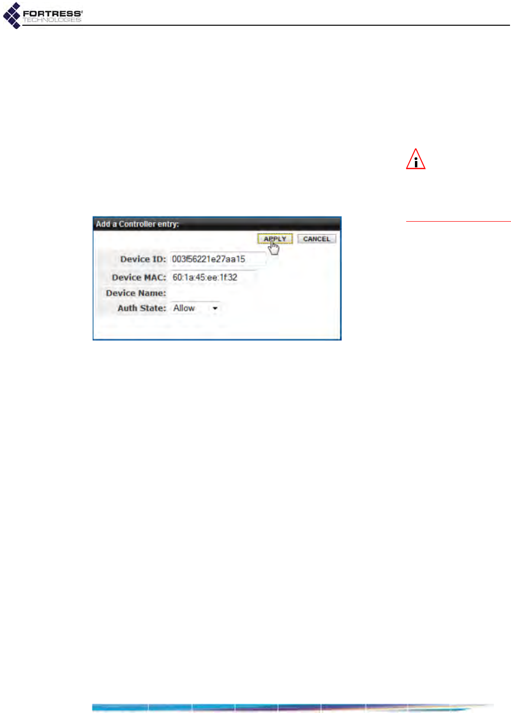
Bridge GUI Guide: Security Configuration
154
Allow - (the default) auto-populating controller devices will
be allowed to connect.
Pending - auto-populating controller devices require an
administrator to change their individual Auth State settings
to Allow before they can connect.
Deny - auto-populating controller devices are not allowed to
connect.
NOTE: The
Bridge’s Device ID
and MAC address are
displayed in the System
Info frame on Configure
-> Administration.
You can also manually add controller devices to the Bridge’s
Authorized Controller Devices list.
In order to add a device manually, you must specify its MAC
address and Fortress-generated, 16-digit hexadecimal Device
ID.
Figure 4.18. Advanced View
Add a Controller entry
dialog, all platforms
Access Control functions are available only in Advanced View.
To configure the Controller ACL:
1Log on to the Bridge GUI through an Administrator-level
account and select ADVANCED VIEW in the upper right corner
of the page, then Configure -> Access Control from the
menu on the left.
2In the Access Control screen’s Controller Access List frame,
select the Default Auth State for auto-populating (and
manually configured) Controller devices (described above).
3In the same frame:
If you want to add a device to the Bridge’s Controller
ACL:
Click NEW CONTROLLER.
In the Add a Controller entry dialog, enter the Device
ID and the Device MAC address for the Controller.
Select the Auth State at which the Controller will be
permitted to connect (described above).
and/or
If you want to edit the entry of an existing entry:
Click the EDIT button for the entry.
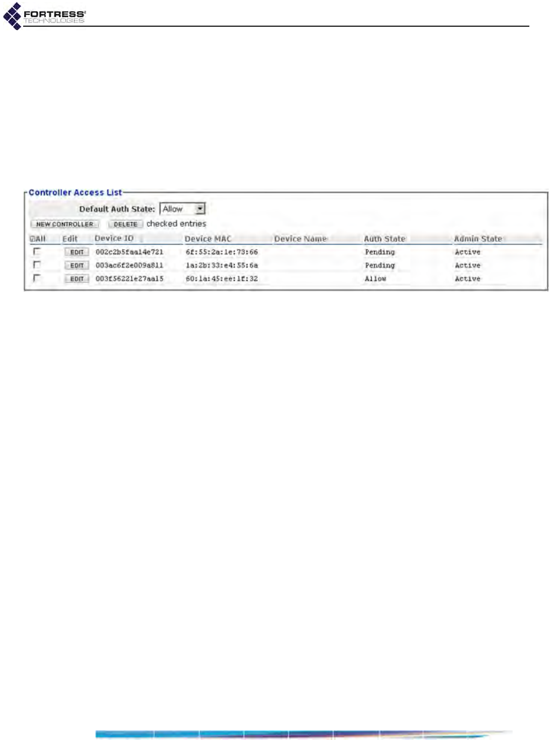
Bridge GUI Guide: Security Configuration
155
In the Edit a Controller entry dialog, edit the MAC
address or Auth State (you cannot change the
Device ID).
Click APPLY in the dialog (or CLOSE it to cancel the
action).
4When you have finished adding and/or editing Controller
entries, click APPLY in the upper right of the screen (or
RESET screen settings to cancel your changes).
The Controller Access List reflects your changes.
Figure 4.19. Advanced View
Controller Access List
frame, all platforms
To delete Controller devices from the ACL:
You can delete a single Controller entry or all Controller
devices on the Bridge’s ACL.
1Log on to the Bridge GUI through an Administrator-level
account and select ADVANCED VIEW in the upper right corner
of the page, then Configure -> Access Control from the
menu on the left.
2In the Access Control screen’s Controller Access List frame,
If you want to delete a single entry, click to place a
check in the box beside it; then the DELETE button
above the list.
or
If you want to delete all entries, click All to place a
check in all entries’ boxes; then click the DELETE button
above the list.
3Click OK in the confirmation dialog (or Cancel the deletion).
The Controller ACL reflects your changes.
4.5.3 Cleartext Device Access Control
You may want to allow certain devices to pass unencrypted
data, or clear text, on the Bridge’s encrypted interfaces. These
might be wireless 3rd-party APs (access points) or Trusted
Devices that require cleartext access to the encrypted zone.
Network security is maximized when:
1the smallest possible number of cleartext devices are
permitted encrypted zone access
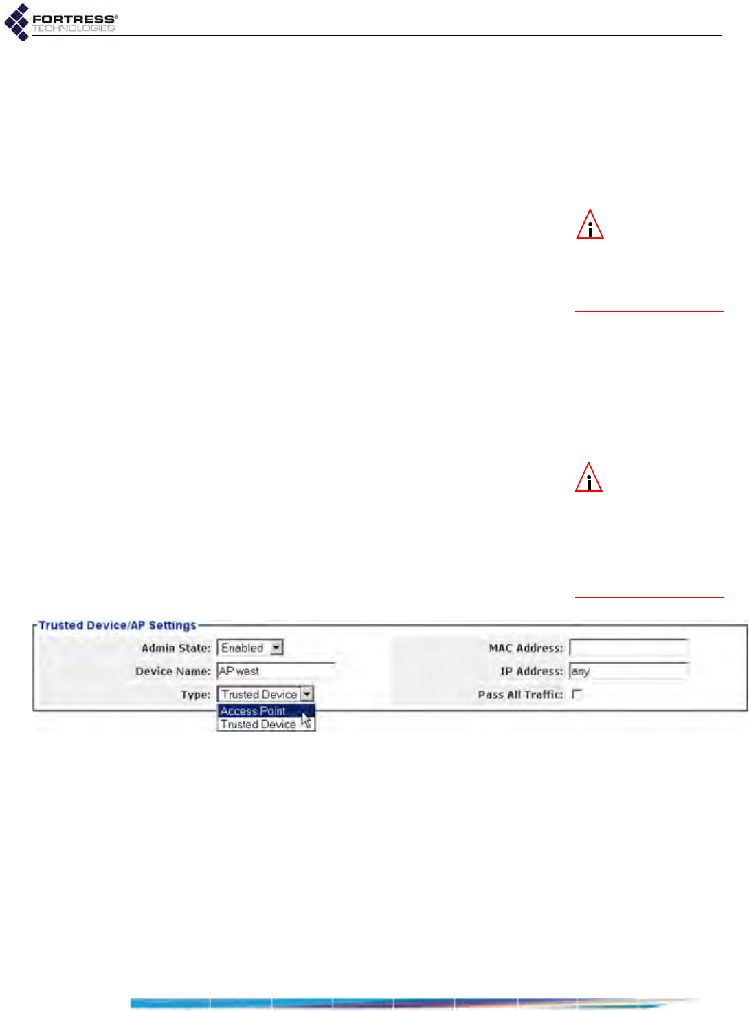
Bridge GUI Guide: Security Configuration
156
2the smallest effective set of accessible ports is specified for
each
3cleartext device access is enabled only when needed
Once cleartext access to encrypted interfaces has been
established for a device, the Bridge uses the device’s MAC
address, IP address and port number to authenticate it on the
network.
NOTE: The cur-
rent Cleartext traf-
fic setting is shown in
the upper left of all
Bridge GUI screens (re-
fer to Section 5.1).
Configured cleartext devices will not be allowed to pass traffic
in the Bridge’s encrypted zone, unless Cleartext Traffic has
been Enabled (on Advanced View -> Configure -> Security ->
Security Settings, refer to Section 4.1.10). Cleartext Traffic is
Disabled by default.
These settings are available regardless of specified cleartext
Device Type (below):
Admin State - determines whether the device’s cleartext
access to the Bridge’s encrypted zone is Enabled or
Disabled (the default).
Device Name - establishes a descriptive name for the
device. Access rules, whether for Trusted Devices or APs
must be uniquely named on the Bridge.
NOTE: STP and
Cisco® Layer 2,
VLAN management
traffic to or from switch-
es in the Bridge’s en-
crypted zone requires
Pass All Traffic to be en-
abled (checked).
MAC Address - provides the MAC address of the device.
IP Address - provides the network address of the device.
Device Type - establishes the cleartext device as a wireless
Access Point or a designated Trusted Device.
Pass All Traffic - determines whether the Bridge will filter
OSI Layer 2 traffic from the device (checkbox clear, the
default) or allow all OSI Layer 2 traffic to pass to and from
the device in the encrypted zone (box checked).
Figure 4.20. Advanced View
Trusted Device/AP Settings
frame, all platforms
4.5.3.1 3rd-Party AP Management
Bridges equipped with one or more radios can themselves
serve as wireless access points (APs), as described in Section
3.3.4.
The Bridge-secured network can additionally include 3rd-party
wireless APs, which will pass network traffic normally
regardless of whether you have configured the Bridge to allow
administrative access to the AP.
If you want to manage a 3rd-party AP on the Bridge-secured
network, you must communicate with it in clear text (the AP
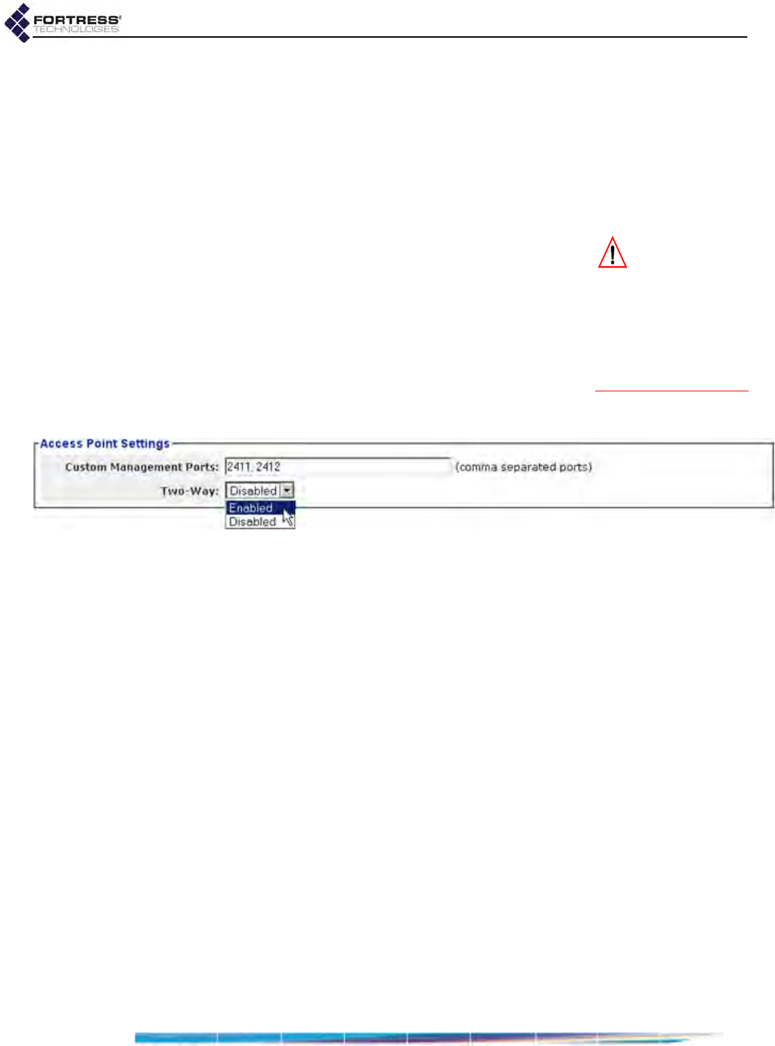
Bridge GUI Guide: Security Configuration
157
having no means to decrypt/encrypt Fortress MSP traffic). To
do so, you must configure cleartext access for the AP.
Cleartext access configured to permit direct communication
with APs can represent a security risk: APs’ MAC addresses
are necessarily transmitted in clear text and could be spoofed.
Fortress recommends creating and enabling cleartext device
access only as required and filtering that traffic to permit only
the necessary minimum network access for the device.
CAUTION: To max-
imize network se-
curity, permit the fewest
possible cleartext devic-
es to access encrypted
interfaces and to config-
ure the smallest effec-
tive set of accessible
ports for each.
These settings are available only when Device Type (Section
4.5.3) is Access Point:
Custom Management Ports - specifies ports by number
(separate multiple entries by commas, no spaces).
Two-Way - permits two-way communication for AP
management (Enabled) or allows only one-way
communication from the Bridge to the AP (Disabled, the
default), according to the requirements of the AP. When
Trusted Device is the selected Device Type, this field is
greyed out.
Figure 4.21. Advanced View
Access Point Settings
frame, all platforms
4.5.3.2 Trusted Devices
Some wireless devices—IP phones, digital scales or printers,
for example—are not equipped to run additional software such
as the Fortress Secure Client.
In order to allow such a device onto the network, the Fortress
Bridge must be configured to identify it as a Trusted Device—
essentially a specialized, cleartext network device for which the
narrowest possible access rules are applied.
Visitor Access through Trusted Devices
Visitors to your facilities can be granted temporary access to
the WLAN by configuring Trusted Devices, with appropriate
access rules, through which visitors can connect their mobile
devices. Trusted Devices created to provide access to visiting
mobile device are managed no differently from other Trusted
Devices.
To limit visitor access to the Web, select only the Web group of
port numbers from the checkbox options in the Access
Management Rules frame.
Trusted Devices for visitors are managed no differently from
other Trusted Devices. You should delete any Trusted Device
access rule when it is no longer required.

Bridge GUI Guide: Security Configuration
158
Well Known Trusted Device Ports
Well Known TD Ports - specifies accessible groups of well
known ports, grouped by function. Well Known TD Ports options
are available only when Device Type (Section 4.5.3) is Trusted
Device.
Figure 4.22. Advanced View
Well Known TD Ports
frame, all platforms
Access Control functions are available only in Advanced View.
To configure cleartext access for APs and Trusted Devices:
NOTE: Cleartext
Traffic must be En-
abled in order for any
AP or Trusted Device to
pass traffic on encrypt-
ed interfaces (refer to
Section 4.1.10).
1Log on to the Bridge GUI through an Administrator-level
account and select ADVANCED VIEW in the upper right corner
of the page, then Configure -> Access Control from the
menu on the left.
2In the Access Control screen’s Controller Access List frame,
click NEW TD/AP, and on the resulting screen:
On the APs/Trusted Devices screen, configure basic
cleartext device settings in the Trusted Device/AP
Settings frame.
If Access Point was selected for Type in the preceding
step, configure Access Point Settings for the device.
or
If Trusted Device was selected for Type in the preceding
step, configure Well Known TD Ports for the device.
3Click APPLY in the upper right of the screen (or CANCEL your
addition).
Devices for which cleartext access to the encrypted zone has
been configured are displayed on the Trusted Device/AP Access
List.
To edit APs and Trusted Device cleartext access:
1Log on to the Bridge GUI through an Administrator-level
account and select ADVANCED VIEW in the upper right corner
of the page, then Configure -> Access Control from the
menu on the left.
2In the Access Control screen’s Controller Access List frame,
click EDIT button beside the device entry you want to edit.
3On the resulting screen, change those settings you want to
reconfigure.
4Click APPLY in the upper right of the screen (or CANCEL your
changes).

Bridge GUI Guide: Security Configuration
159
To delete cleartext access for APs and Trusted Device:
NOTE: Disabling
or deleting cleart-
ext access for an AP
does not disable the ac-
cess point: it continues
to pass network traffic
among devices on the
encrypted network.
You can delete cleartext access to the Bridge’s encrypted zone
for a single device or for all devices.
1Log on to the Bridge GUI through an Administrator-level
account and select ADVANCED VIEW in the upper right corner
of the page, then Configure -> Access Control from the
menu on the left.
2In the Access Control screen’s Controller Access List frame:
If you want to delete one or more selected cleartext
devices, click to check the box(es) for the cleartext
device(s) you want to delete.
or
If you want to delete all cleartext devices, click All to
place a check in the box of every device.
3Click DELETE.
4Click OK in the confirmation dialog (or Cancel the deletion).
The cleartext device ACL reflects your changes.
4.6 Remote Audit Logging
The Bridge supports remote audit logging using the syslog
standard with an external server, and you can specify a
threshold severity level for the events sent to syslog.
You can also specify a number of parameters by which to
separately filter administrator and connecting device activity for
audit logging.
4.6.1 Enabling Audit Logging
NOTE:
Remote log-
ging settings do
not affect which events
th
e Bridge lo
gs locally,
in the native
Event Log
(refer to Section 5.9).
To send audit log messages from the Bridge to an external
server, you must enable the function and enable and configure
the Bridge’s connection to the syslog server.
You can send logged events of every severity level to the
remote server, or you can globally configure the Bridge to send
a only a subset of messages, filtered by severity level, for audit
logging.
Logging/Auditing functions are available only in Advanced View.
Figure 4.23. Advanced View
Global Logging Settings
frame, all platforms
To enable remote audit logging:
1Log on to the Bridge GUI through an Administrator-level
account and select ADVANCED VIEW in the upper right corner

Bridge GUI Guide: Security Configuration
160
of the page, then Configure -> Logging/Auditing from the
menu on the left.
2In the Logging/Auditing screen’s Global Logging Settings
frame:
In Auditing - click Enabled to turn audit logging on.
In Remote Log Storage - click Enabled to direct the
Bridge to use the network syslog server.
In Remote Log Host - enter the IP address of the syslog
server.
In Severity of Messages Retained - select from the
dropdown the minimum severity level for which
messages will be sent to the external audit log.
At the default setting of Critical, for example, the Bridge
will send only those messages at the Critical severity
level, and not those at lower levels of severity (Warning,
Error, and Informational messages).
3Click APPLY in the upper right of the screen (or RESET
screen settings to cancel your changes).
Audit logging is Enabled by default, but the external syslog
server function is Disabled and no Remote Log Host is
configured.
Disable audit logging by selecting Disabled in Auditing.
4.6.2 Administrative Audit Logging
NOTE: Individual
administrative ac-
counts’ Audit settings
(refer to Section 2.2.2.4)
override all other audit
logging settings, and the
audit settings associated
with a given MAC ad-
dress (Section 4.6.2.3)
override those in Global
Auditing Settings.
You can globally configure the way in which administrative
activity on the Bridge is filtered for audit logging.
Global settings will apply to an administrative session only
when the Audit setting for the administrator’s individual account
is set to Auto (refer to Section 2.2.2.4). At the default Audit
setting of Required, all activity on an administrative account is
sent to the audit log without regard to global settings.
Additionally, the settings that filter administrative events by
User Interface, Fortress Security and Interface Type (sections
4.6.2.1 and 4.6.2.2) will apply only when the administrator is
logged on from a MAC address that is not itself subject to the
separately configured MAC Auditing Settings (Section 4.6.2.3).
If an administrator logs on from a listed MAC address, the audit
logging configuration for that MAC address is applied.
Finally, audit logging must be enabled and an external syslog
server configured on the Bridge before events can be sent to
the audit log (refer to Section 4.6.1).
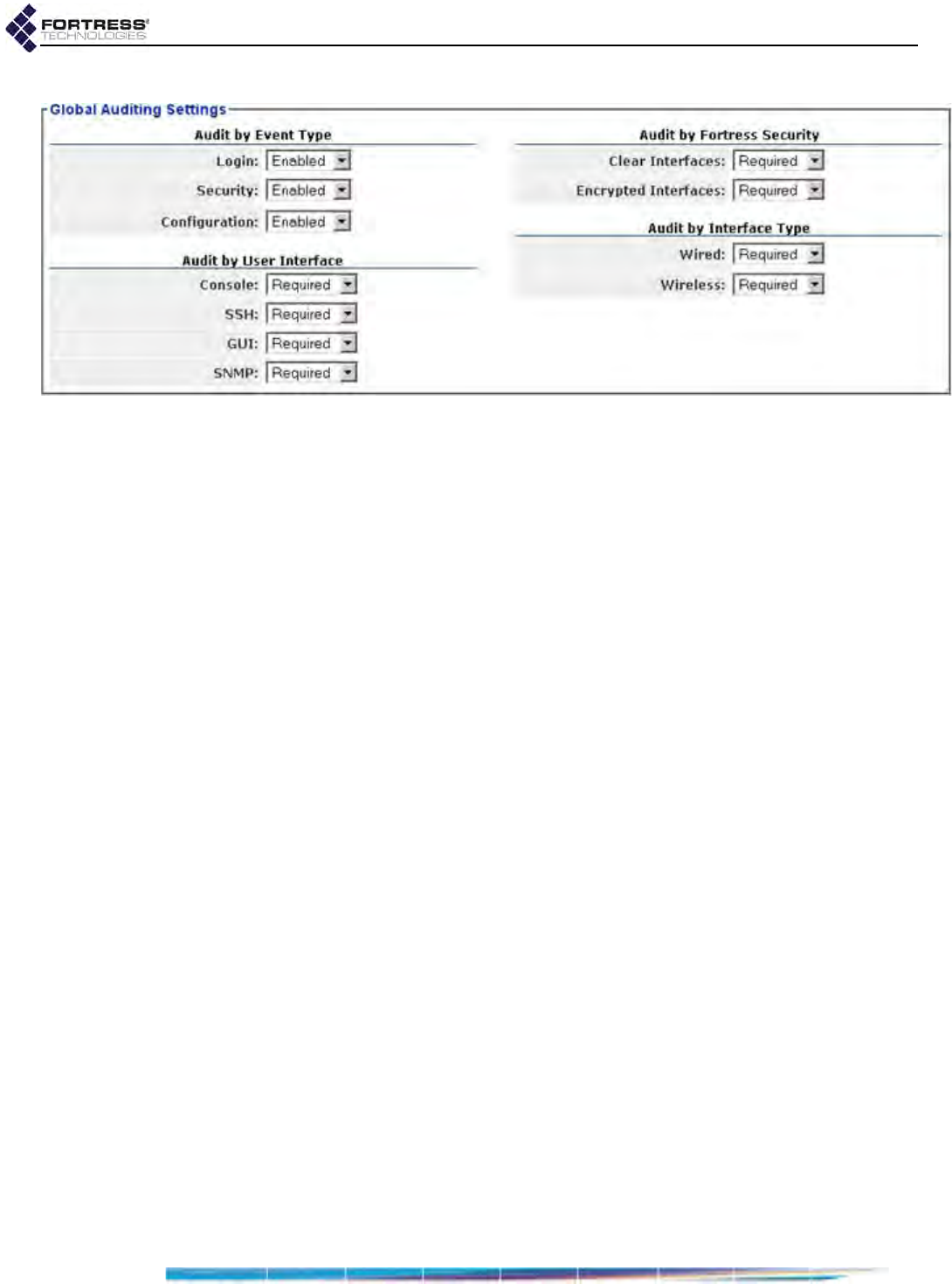
Bridge GUI Guide: Security Configuration
161
Figure 4.24. Advanced View
Global Auditing Settings
frame, radio-equipped platforms
4.6.2.1 Logging Administrative Activity by Event Type
You can specify which events can be sent to the audit log by
three broad types:
Login - When Enabled, logon activity by subject
administrators can be sent to the audit log. When Login is
Disabled, the logon activity of subject administrators will not
be sent.
Security - When Enabled, if Configuration (below) is also
Enabled, any changes made by subject administrators to
the Bridge’s security settings can be sent to the audit log.
When Security is Disabled, security reconfiguration by
subject administrators will not be sent.
Configuration - When Enabled, if Security (above) is also
Enabled, all changes made by subject administrators to the
Bridge’s configuration can be sent to the audit log. If
Security is Disabled when Configuration is Enabled, all
changes except those to security settings can be logged.
When Configuration is Disabled, Bridge reconfiguration by
subject administrators will not be sent (even if Security
logging is Enabled).
In addition to the conditions described at the beginning of this
section (4.6.2), whether or not events of an Enabled type are
actually sent to the audit log depends on whether the event
meets the interface and Fortress security status criteria for
audit logging configured in the rest of the Global Auditing
Settings frame (below).
All three event types are Enabled by default.
4.6.2.2 Logging Administrative Activity
by Interface and Fortress Security Status
You can filter administrative activity sent to the audit log by the
kind of management interface the administrator is logged on

Bridge GUI Guide: Security Configuration
162
through and whether the interface is encrypted or clear, wired
or wireless:
Audit by User Interface - There are four ways an
administrator can access the Bridge:
Console - a serial connection to the chassis Console port
SSH - a Secure Shell connection to the Bridge CLI
GUI - an HTTPS (Hypertext Transfer Protocol Secure)
connection to the Bridge GUI
SNMP - Simple Network Management Protocol
transactions
Audit by Fortress Security - All remote management
connections to the Bridge must be made on one of its Clear
Interfaces (on which Fortress Security is Disabled) or on one
of its Encrypted Interfaces (on which Fortress Security is
Enabled).
NOTE: The Wire-
less interface type
does not apply to Bridg-
es without radios and
will not be present for
those models (refer to
Table 1.1 on page 3).
Audit by Interface Type - All remote management
connections must be made through either a Wired interface
(Ethernet port) or a Wireless interface, a BSS (Basic
Service Set) on one of the Bridge’s radios.
The Bridge handles audit event logging according to a
hierarchy of categories, ordered as shown above.
Each of the interface and Fortress security status controls for
audit event logging can be set to one of three behaviors:
Required - events originating from that interface or from an
interface with the specified Fortress security status will be
logged, provided they are not Prohibited in a superior audit
setting.
Prohibited - events originating from that interface or from an
interface with the specified Fortress security status will not
be logged, provided they are not Required in a superior
audit setting
Auto - events originating from that interface or from an
interface with the specified Fortress security status will be
logged according to whether they are Prohibited or Required
in a superior setting. If all applicable superior settings are at
Auto, events will be logged according to any applicable
inferior settings.
In short, events are checked against the audit settings for User
Interface, Fortress Security and Interface Type, in that order, and
logged according to the first applicable Required or Prohibited
setting.
Audit logging is Required by default for all interfaces, regardless
of user, type, or Fortress security status.
Logging/Auditing functions are available only in Advanced View.

Bridge GUI Guide: Security Configuration
163
To configure audit logging
by event type, Fortress security status and interface:
1Log on to the Bridge GUI through an Administrator-level
account and select ADVANCED VIEW in the upper right corner
of the page, then Configure -> Logging/Auditing from the
menu on the left.
2In the Logging/Auditing screen’s Global Auditing Settings
frame, enter new values for the controls you want to
configure. (Your options are described in sections 4.6.2.1
and 4.6.2.2).
NOTE: Changes to
administrative au-
dit logging take effect at
the next administrator
logon.
3Click APPLY in the upper right of the screen (or RESET
screen settings to cancel your changes).
4.6.2.3 Logging Administrative Activity by MAC Address
You can filter administrative activity sent to the audit log by the
MAC address from which it originates.
The same categories of interfaces and Fortress security status
of origin used to globally configure administrative audit logging
apply when you configure audit event logging by individual
MAC address (refer to Section 4.6.2.2).
Audit by User Interface - includes the possible administrative
network interfaces: SSH, GUI, SNMP
Audit by Fortress Security - includes Clear Interfaces and
Encrypted Interfaces.
NOTE: The Wire-
less interface type
does not apply to Bridg-
es without radios and
will not be present for
those models (refer to
Table 1.1 on page 3).
Audit by Interface Type - includes Wired and Wireless
interfaces.
Each control can be set to one of the same three behaviors
described in Section 4.6.2.2: Required, Prohibited, Auto.
Events originating from the MAC address are checked against
the audit settings for User Interface, and Fortress Security and
Interface Type, in that order, and logged according to the first
applicable Required or Prohibited setting.
In new MAC address entries, logging is Required by default for
all interfaces, regardless of user, type, or Fortress security
status.
Figure 4.25. Advanced View
MAC Auditing Settings
frame, all platforms
To configure audit logging by MAC address:
1Log on to the Bridge GUI through an Administrator-level
account and select ADVANCED VIEW in the upper right corner
of the page, then Configure -> Logging/Auditing from the
menu on the left.
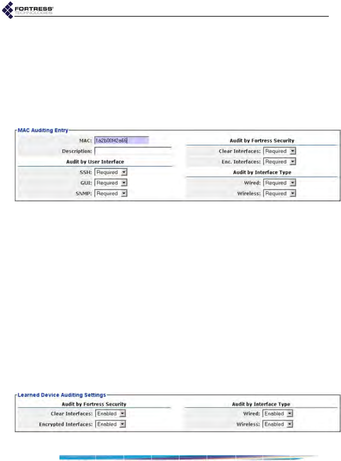
Bridge GUI Guide: Security Configuration
164
2In the Logging/Auditing screen’s Mac Auditing Settings
frame, click NEW MAC ENTRY.
3In the resulting screen’s MAC Auditing Entry frame, enter
the MAC address you want to configure for audit logging
and, optionally, a description of up to 250 alphanumeric
characters, symbols and/or spaces.
4In the same frame, enter new values for the Audit by...
controls you want to configure (described above).
5Click APPLY in the upper right of the screen (or CANCEL the
addition).
Figure 4.26. Advanced View
MAC Auditing Entry
frame, all radio-equipped platforms
You can recall the MAC Auditing Entry frame for a configured
MAC address by clicking the EDIT button to the left of its entry
on MAC Auditing Settings. You can then reconfigure audit
logging for that MAC address and APPLY your changes.
Delete a MAC address from audit logging by clicking to place a
check in the box to the left of its entry on MAC Auditing Settings
and then clicking DELETE at the top of the frame. Delete all
MAC addresses by clicking All to check all their boxes and then
DELETE.
4.6.3 Learned Device Audit Logging
The Bridge detects devices connecting to the network it
secures. These events are logged locally regardless of how
Learned Device Auditing Settings are configured.
When audit logging is enabled and an external syslog server is
configured on the Bridge (refer to Section 4.6.1), you can
configure the Bridge to send events associated with Learned
Device connections to the audit log, and you can filter logged
events by the Fortress security status and type of interface on
which the device is learned.
Figure 4.27. Advanced View
Learned Device Auditing Settings
frame, all radio-equipped platforms

Bridge GUI Guide: Security Configuration
165
To configure learned device audit logging:
1Log on to the Bridge GUI through an Administrator-level
account and select Configure -> Logging/Auditing from the
menu on the left.
2On the Logging/Auditing screen, in the Learned Device
Auditing Settings frame, click to ENABLE/DISABLE audit event
logging of devices learned:
NOTE: The Wire-
less interface type
does not apply to Bridg-
es without radios and
will not be present for
those models (refer to
Table 1.1 on page 3).
on one of the Clear Interfaces
on one of the Encrypted Interfaces
on a Wired interface
on a Wireless interface
3Click APPLY in the upper right of the screen (or RESET
screen settings to cancel your changes).

Bridge GUI Guide: Monitoring
166
Chapter 5
System and Network Monitoring
The Bridge GUI provides access to an array of system and
operating information on Configure -> Administration and
under Monitor on the main menu and displays the FIPS
indicators described below on every screen.
5.1 FIPS Indicators
In the upper left of Bridge GUI screens, above the main menu,
the Bridge reports three pieces of information relevant to
Federal Information Processing Standards (FIPS) 140-2
Security Level 2.
Figure 5.1. FIPS indicators, all screens, all platforms
Mode - is the Operating Mode, as configured on Configure
-> Security and explained in Section 4.1.1
FIPS - Bridge operation complies with FIPS 140-2
Security Level 2.
Normal - Bridge operation can be secured but does not
meet FIPS requirements.
NOTE: In FIPS ter-
minology, the
Bridge is in FIPS Bypass
Mode (BPM) when cleart-
ext is permitted to pass
on any of its encrypted
interfaces.
Cleartext - is the Cleartext Traffic setting, as configured on
Configure -> Security and described in Section 4.1.10.
Enabled - the Bridge allows clear text from specified
devices to pass on its encrypted interfaces (Ethernet
ports or radio BSSs on which Fortress Security is
Enabled).
Disabled - the Bridge allows no clear text to pass on any
encrypted interface.
Status - when the Bridge is in FIPS operating mode,
indicates the current state of FIPS self testing (refer to
Section 4.1.8). The Bridge’s color indicator to the left of
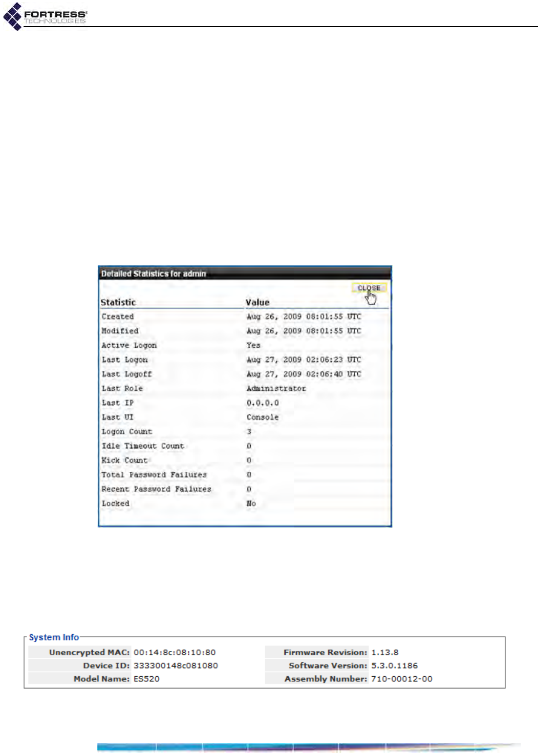
Bridge GUI Guide: Monitoring
167
these fields displays the basic FIPS state; the text output
can reiterate or augment the indicator:
Green - Healthy - The Bridge passed the last FIPS tests.
Yellow - Testing - The Bridge is running FIPS self tests.
Red - Critical - The Bridge is in FIPS failed state and will
reboot (refer to Section 4.1.1).
A Bridge in Normal operating mode always displays a
Status of Healthy.
5.2 Administrative Account Details
In Advanced View, you can click the Username of any account
listed in Configure -> Administration -> Administrator Settings for
details of the account’s creation and modification and a record
of logon activity on the account since the Bridge last booted.
Figure 5.2. administrator
Detailed Statistics
dialog, all platforms
5.3 System Information
In addition to the configured (or default) values of the settings
on the Administration screen (Configure -> Administration), the
Bridge GUI displays basic System Information at the top of the
screen.
Figure 5.3.
System Info
frame, all platforms (with relevant changes of
Model Name
)
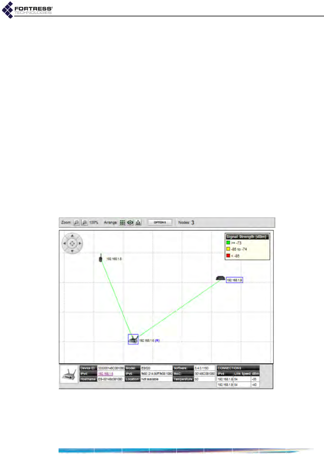
Bridge GUI Guide: Monitoring
168
System Information displays:
Unencrypted MAC - the MAC address of the Bridge’s
management interface
Device ID - the Fortress Device ID, as uniquely generated
for each device on a Fortress-secured network and used,
when applicable, for device authentication.
Software Version/Firmware Revision - the Fortress software
and firmware currently running on the Bridge
The Model Name and Assembly Number - the Fortress
hardware device on which the Bridge software is running
5.4 Topology View
On Bridges equipped with one or more radios (refer to Table
1.1 on page 3) and operating as a node in a wireless network,
the Topology View screen provides a visual representation of
the network to which the Bridge belongs. The screen displays
an icon for the Bridge you are currently logged onto—identified
by a blue box around the its IP address—and each of the
Bridges (nodes) the current Bridge is connected to. When you
first view this screen, the Bridges are arranged randomly, but
within your frame of view.
Figure 5.4.
Topology View
, all radio-equipped platforms (with relevant changes of current device indicator)
Bridges on Monitor -> Topology View are connected by lines,
which, by default, indicate by color the Link Speed in Mbps of
each connection. You can change screen OPTIONS to have the
lines indicate the Signal Strength (dBm) or to remove the lines
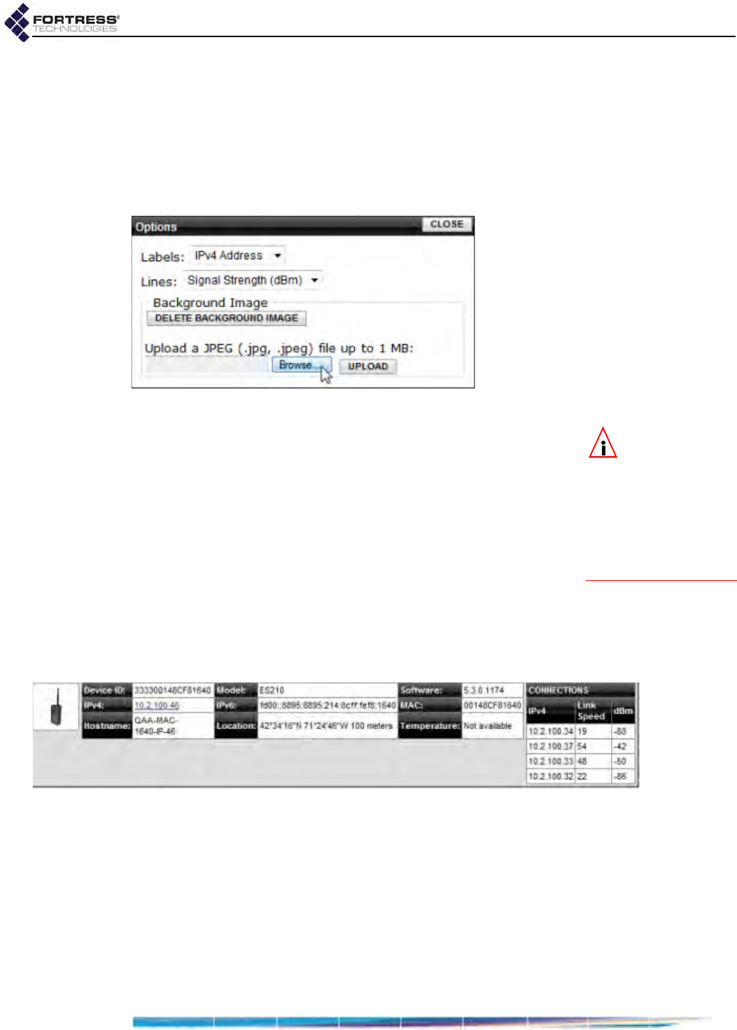
Bridge GUI Guide: Monitoring
169
(No Lines). The legend in the top right corner of the screen
shows what the lines depict and the relative ranges indicated
by Green, Yellow, and Red status colors.
By default, Bridges in the Topology View are labeled with their
IPv4 addresses. Alternatively, you can change the OPTIONS to
label network Bridges by Hostname, IPv6 Address, MAC Address,
Device ID, or No Labels.
Figure 5.5. Topology View Options dialog, all radio-equipped platforms
NOTE: Clicking an
Arrange icon over-
rides each bridge’s pre-
vious placement, so you
may not want to use
these icons if you have
spent time manually
dragging each node into
place.
You can view the nodes on the default grid or you can upload a
map or satellite image of your location to use as the
background for the Topology View (refer to Section 5.4.1). If you
use your own image, you can then manually place each of the
nodes near their physical location to make the view more
representative.
Alternatively, you can use the Arrange icons at the top of the
screen to view the nodes in a grid, ellipse or in an STP tree
configuration based on the STP root. The STP tree view is not
available until an STP root has been discovered, which can
take a few seconds after the page loads. In STP tree view, the
zoom buttons are disabled and the background image and
associated options are hidden.
Figure 5.6.
Topology View
device details frame (for an ES210), all radio-equipped platforms
Click any Bridge icon to open a frame at the bottom of the
screen. The frame displays the selected Bridge’s Device ID,
IPv4 Address, Hostname, Model, IPv6 Address, Location,
Software version, MAC Address, and Temperature. Any field
that is not available for the selected Bridge is left blank. The
IPv4 Address serves as a link to that Bridge’s GUI logon
screen.

Bridge GUI Guide: Monitoring
170
5.4.1 Uploading a Background Image
You can upload a JPEG (.jpg) image file of up to 1 MB, typically
a map or satellite image, to use as the Topology View
background.
1Log on to the Bridge GUI through an Administrator-level
account and select Monitor -> Topology View from the menu
on the left.
2On the Topology View screen, click OPTIONS.
3On the resulting screen, click Browse.
4On the resulting screen, navigate to the image file you want
to upload and click OK.
5Click UPLOAD.
6Once the image has loaded, click CLOSE.
The image is now the background of the Topology View screen.
You can reposition your image or zoom the view in or out as
needed.
5.5 Connections and DHCP Lease Monitoring
The tabs under Monitor -> Connections provide monitoring of all
devices currently connected to the Bridge and simple network
access controls for devices connected to the Bridge’s
encrypted interface(s). The last tab displays current leases on
the Bridge’s internal DHCP servers, when enabled.
Each tab heading shows the type of connection displayed on
the tab and, in brackets, a current count of connected devices
of that type.
The Bridge’s three status icons apply to the Connections shown
on all tabs.
successful connection
unknown connection
blocked connection
You can sort the entries on any Connections tab, in ascending
or descending order, by any displayed parameter, by clicking
on the corresponding column heading.
5.5.1 Associations Connections
NOTE:
Associations
are not relevant to
Bridge models that do
not contain radios.
On Bridges equipped with one or more radios (refer to Table
1.1 on page 3), the Associations tab of the Monitor ->
Connections screen shows current connections to any BSSs

Bridge GUI Guide: Monitoring
171
configured (as APs or FP Mesh Access interfaces) to provide
network access to wireless devices within range.
Figure 5.7.
Connections
screen,
Associations
tab, all radio-equipped platforms
Radio -
identifies the radio to which the device is connected.
BSS - shows the name of the Basic Service Set through
which the device is connected.
MAC Address - displays the Media Access Control address
of the associated device.
Wi-Fi Security - displays the IEEE 802.11i security protocol
the device is using.
Zone - indicates whether the BSS to which the device is
connected is Encrypted (Fortress Security is Enabled) or
Clear (Fortress Security is Disabled).
Auth State - the state of the device’s network authentication
process. Possible values include:
Unknown - connected, not yet ready to proceed
Initial - ready to proceed, waiting for device to respond
Started - response received, authentication in process
Success - authentication succeeded: network access
permitted
Locked - authentication failed: network access blocked
Date Learned - the start date/time of the device’s current
session
5.5.2 Bridge Links
NOTE:
Bridge Links
are not relevant to
Bridge models that do
not contain radios.
On Bridges equipped with one or more radios (refer to Table
1.1 on page 3), the Bridge Links tab of the Connections screen
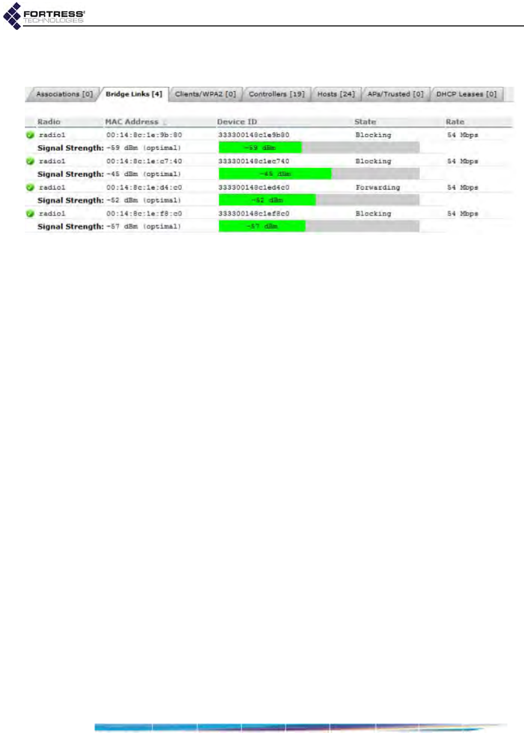
Bridge GUI Guide: Monitoring
172
shows current connections to any BSS the Bridge configured
as the bridging interface in a network of Fortress Bridges.
Figure 5.8.
Connections
screen,
Bridge Links
tab, all radio-equipped platforms
radioN - identifies the radio on which the BSS forming the
bridging link is configured.
Signal Strength - dynamically displays the strength of the
RF signal forming the link, measured in real time at one-
second intervals, in decibels referenced to milliwatts.
MAC Address - the Media Access Control address of the
connected network node
Device ID - the Device ID—the unique hexadecimal
Fortress-generated identifier—which provides device
authentication on the Bridge-secured network—of the
connected network node
State - the bridging status of the connected network node.
Possible values and meanings depend on the Bridge’s
current Bridging Mode setting (Section 3.2):
When STP is used for bridging, possible values include:
Disabled - the interface is not passing traffic
Forwarding - the interface is passing all traffic
Listening - the interface is listening for BPDUs
(Bridge Protocol Data Units) in order to build its
loop-free path, but is not yet forwarding general
data frames
Blocking - the interface is blocking user traffic
(usually because it is a duplicate or sub-optimal
path)
When FastPath Mesh is used for bridging, possible
values include:
Disabled - the interface is not passing traffic
Forwarding All - the interface is passing all traffic
Blocking - the interface is blocking all traffic
Rate - the maximum data transmission rate of the link in
megabits per second
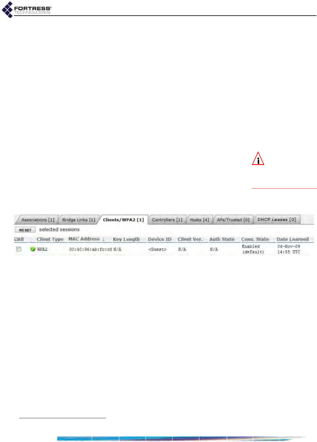
Bridge GUI Guide: Monitoring
173
Because of the radio enhancements and traffic handling
efficiencies defined in the newer standard, bridging links
formed between radios configured to use 802.11n (refer to
Section 3.3.2.2) can show Rate values higher than the
Maximum Rate configured for either individual interface
(refer to Section 3.3.4.10).
5.5.3 Secure Client and WPA2 Device Connections
Fortress Secure Clients connect to an encrypted interface on
the Bridge using Fortress’s Mobile Security Protocol (MSP).
Secure Client connections can be made through an Ethernet
interface configured to apply Fortress Security (refer to Section
3.7.4) or through a BSS (Basic Service Set) on one of the
Bridge’s radios that has been configured to apply Fortress
Security (refer to Section 3.3.4.13).
NOTE: The WPA2
Client Type applies
only on Bridges
equipped with one or
more radios.
WPA2 (Wi-Fi Protected Access 2) clients connect to the Bridge
using the 802.11i WPA2 security standard through a BSS on
one of the Bridge’s radios that has been configured to use the
same standard: WPA2, WPA2-Mixed, WPA2-PSK, or WPA2-Mixed-
PSK (refer to Section 3.3.4.14).
Secure Client and WPA2 connections are shown on the Clients/
WPA2 tab of the Connections screen.
Figure 5.9.
Connections
screen,
Clients/WPA2
tab, all platforms8
The Connections screen displays these attributes of the
connected device:
Client Type - whether the device is an MSP (Fortress
Secure) Client, or a WPA2 Client.
MAC Address - the Media Access Control address of the
Client device
Key Length - the key establishment method (refer to Section
4.1.3) used to secure the current session
Device ID - if the device is an MSP Client, the device’s
unique, hexadecimal, Fortress-generated identifier, which
provides device authentication on the Bridge-secured
network (when device authentication is enabled). WPA2
client devices are not assigned Device IDs.
Client Ver. - if the device is a Fortress Secure Client, the
version of the Fortress software currently running on the
connected device. WPA2 client devices, which do not run
Fortress software, report N/A.
8. Associations and Bridge Links tabs absent when no internal radio is present (refer to Table 1.1 on page 3).

Bridge GUI Guide: Monitoring
174
Auth State - the state of the device’s network authentication
process. Possible values include:
Unknown - connected, not yet ready to proceed
Initial - ready to proceed, waiting for Client to respond
Started - response received, authentication in process
Success - authentication succeeded: network access
permitted
Locked - authentication failed: network access blocked
Conn. State - the state of the device’s network connection.
Possible values depend upon whether the Secure Client is
authenticating through the current Bridge or through
another Fortress controller device to which the current
Bridge is connected:
If the Secure Client device is authenticating through the
current Bridge, the state of its connection is reported:
Initializing - key exchange with Client device
initializing
SKey - static keys exchanged with Client device
DKey - dynamic keys exchanged with Client device
Blocked - key exchange with Client device failed
Unbound - Client device is not connecting via
another Fortress controller device when it is
expected to be
Bound - Client device is connecting via another
Fortress controller device, should be followed by
Partner Connection States (below).
Inferior DKey - Received inferior dynamic key from
Client device
Key Failed - key exchange with Client device failed
If the Secure Client device is authenticating through
another Fortress controller device, the state of that
device’s connection to the current Bridge is reported:
Partner Initializing - key exchange with controller
device initializing
Partner Negotiating - static keys exchanged with
controller device
Partner Secure - dynamic keys exchanged with
controller device
Partner Failed - key exchange with controller device
failed
Partner Inferior DKey - Received inferior dynamic
key from controller device
Partner Key Failed - key exchange with controller
device failed
Date Learned - the start date/time of the connected device’s
current session
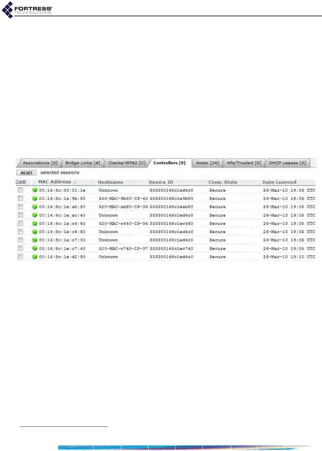
Bridge GUI Guide: Monitoring
175
The controls at the upper left of the tab and individual
checkboxes for connected Clients permit you to:
RESET selected sessions: end their current sessions and
force them to reauthenticate on the Bridge.
When Allow Cached Credentials is Enabled (the default),
locally authenticated users are reauthenticated
transparently, using cached user credentials; when the
function is Disabled, locally authenticated users are
prompted for their login credentials (Section 4.1.13).
5.5.4 Controllers Connections
Fortress Controllers include Fortress ES-series Bridges and the
Fortress Controller, or FC-X (refer to Section 1.3.1 for more
detail). The Bridge GUI displays connections to them on the
Controller tab of the Connections screen.
Figure 5.10.
Connections
screen,
Controllers
tab, all platforms9
MAC Address - the Media Access Control address of the
controller device
Hostname - the network hostname of the device
Device ID - the device’s unique, hexadecimal, Fortress-
generated identifier, which provides device authentication
on the Bridge-secured network (when device authentication
is enabled)
Conn. State - the state of the controller device’s network
connection. Possible values include:
Initializing - key exchange with device initializing
Negotiating - static keys exchanged with the device
Secure - dynamic keys exchanged with the device
Failed - key exchange with the device failed
Inferior DKey - Received inferior dynamic key from the
device
Key Failed - key exchange with the device failed
9. Associations and Bridge Links tabs absent when no internal radio is present (refer to Table 1.1 on page 3).
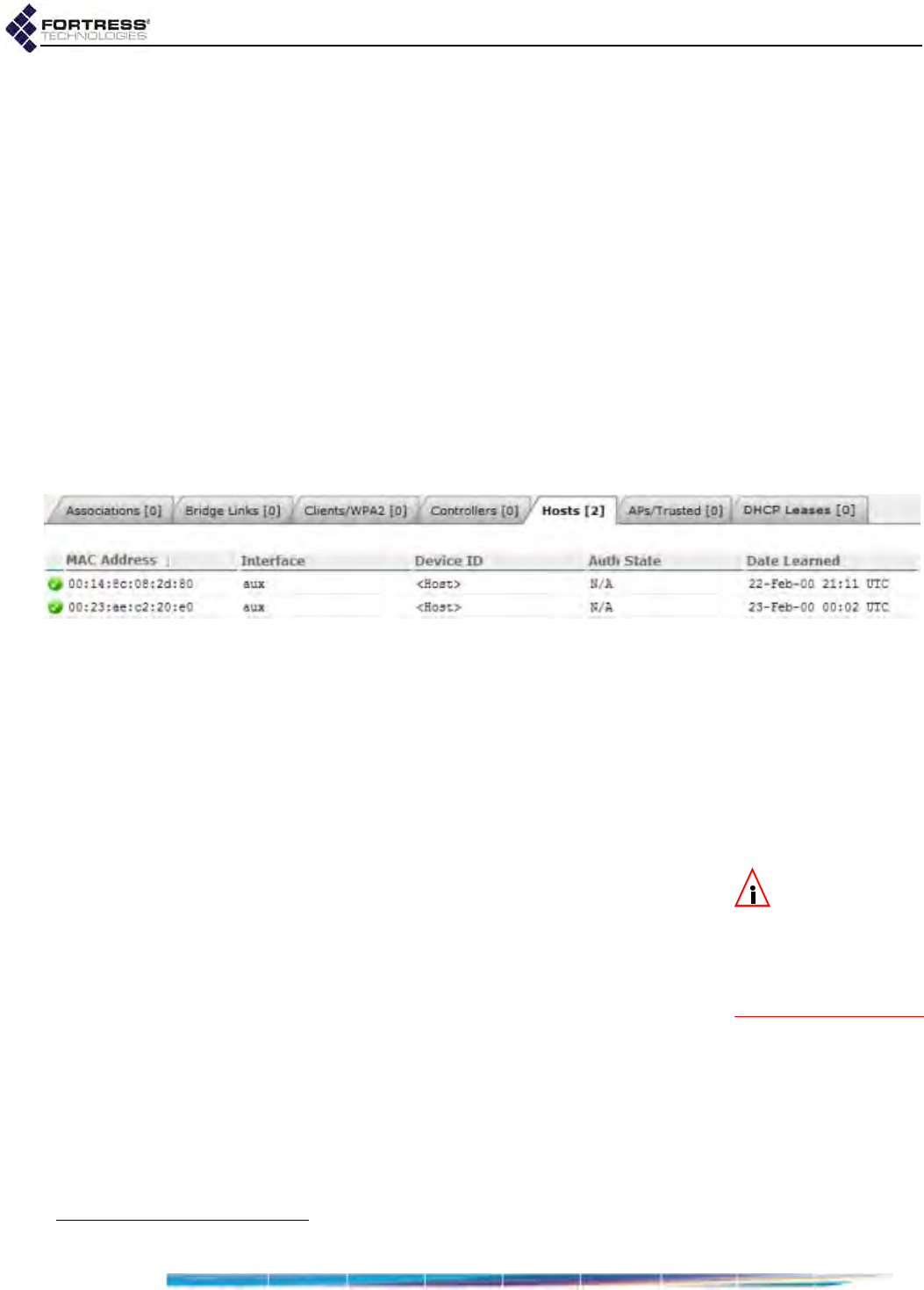
Bridge GUI Guide: Monitoring
176
Update Access ID - Access ID push in progress for the
device
Date Learned - the start date/time of the controller device’s
current session
The controls at the upper left of the tab and individual
checkboxes for connected controller devices permit you to:
RESET selected sessions: end their current sessions and
force them to reauthenticate on the Bridge.
5.5.5 Hosts Connections
Host devices are those connected to the Bridge’s clear
interface(s), either through a clear interface on the current
Bridge or through a clear interface on a remote Bridge with an
encrypted connection to the current Bridge. The Bridge GUI
displays these connections on the Hosts tab of the Connections
screen.
Figure 5.11.
Connections
screen,
Hosts
tab, all platforms10
MAC Address - the Media Access Control address of the
host device
Interface - for devices connected through a clear interface
on the current Bridge, the Bridge interface the host device
is connected through. If the host was learned from a remote
Bridge with a wireless bridging link to the current Bridge,
Interface identifies the internal radio on which the MRP
(mesh radio port) link resides.
NOTE: Device IDs
are unique For-
tress-generated identifi-
ers that enable device
authentication on the
Bridge-secured net-
work (Section 5.3).
Device ID - for devices connected through a clear interface
on a remote Bridge, the Fortress Device ID of the remote
Bridge the host device is connected through. Device ID
does not apply to hosts connected through a clear interface
on the current Bridge, unless the connected host is another
Fortress Bridge (or controller device).
Auth State - for devices connected through a clear interface
on a remote Bridge, the state of the remote Bridge’s
network authentication process. Possible values include:
Unknown - connected, not yet ready to proceed
Initial - ready to proceed, waiting for controller device to
respond
Started - response received, authentication in process
10.Associations and Bridge Links tabs absent when no internal radio is present (refer to Table 1.1 on page 3).

Bridge GUI Guide: Monitoring
177
Success - authentication succeeded: network access
permitted
Locked - authentication failed: network access blocked
Auth State does not apply to hosts connected through a
clear interface on the current Bridge.
Date Learned - the start date/time of the current session
with the host device
5.5.6 AP and Trusted Devices Connections
Trusted Devices or 3rd-Party access points (APs) can be
configured on the Bridge for encrypted interface access
(Section 4.5.3). When these devices are connected, the Bridge
GUI displays them on the AP/Trusted Device tab of the
Connections screen.
Device Type - whether the device is configured as an
Access Point or Trusted Device
MAC Address - the Media Access Control address of the AP
or Trusted Device
IP Address - the IP (version 4) address of the device
Device Name - the Device Name configured for the device
Port List - ports the AP or Trusted Device is configured to
access.
Auth State - the state of the device’s network authentication
process. Possible values include:
Unknown - connected, not yet ready to proceed
Initial - ready to proceed, waiting for device to respond
Started - response received, authentication in process
Success - authentication succeeded: network access
permitted
Locked - authentication failed: network access blocked
Date Learned - the start date/time of the device’s current
session
The controls at the upper left of the tab and individual
checkboxes for connected devices permit you to:
RESET selected sessions: end their current sessions and
force them to reauthenticate on the Bridge.
5.5.7 DHCP Leases
Leases obtained from the Bridge’s internal IPv4 and IPv6
DHCP servers are shown on the DHCP Leases tab on Monitor ->
Connections.
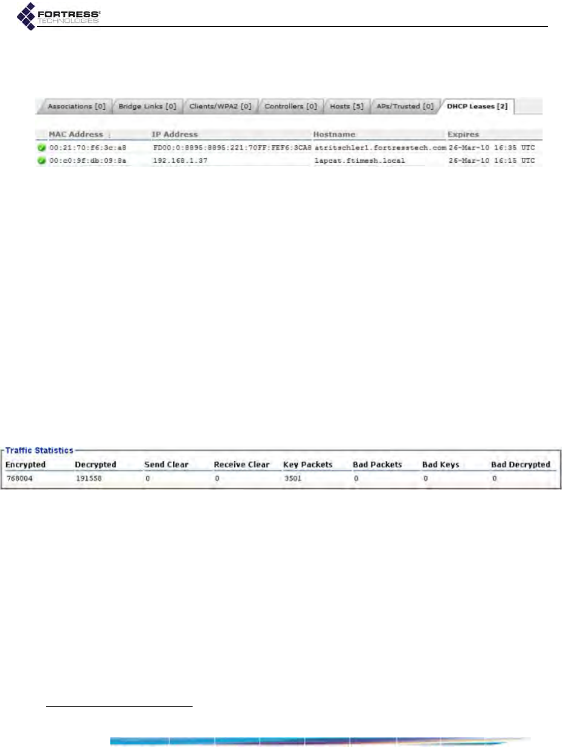
Bridge GUI Guide: Monitoring
178
The MAC Address, IP Address and Hostname of the DHCP
client device are displayed, followed by the date and time the
lease Expires.
Figure 5.12.
Connections
screen,
DHCP Leases
tab, all platforms11
Configuration and operation of the Bridge’s DHCP services are
described in Section 3.6.1.
5.6 Statistics Monitoring
Traffic Statistics at the top of the Monitor -> Statistics screen
displays statistics for overall encrypted-interface traffic.
Subsequent frames provide statistics for each of the Bridge’s
physical or virtual interfaces—including:
physical Ethernet ports
Basic Service Sets configured on the radio(s) internal to the
Bridge (when present)
any VLANs configured on the Bridge.
5.6.1 Traffic Statistics
The packets that the Bridge has transmitted and received the
encrypted interface(s) since cryptographic processing was last
started are shown in the Traffic Statistics frame:
Figure 5.13.
Statistics
screen,
Traffic Statistics
frame, all platforms
Encrypted - encrypted packets—the packets received on a
clear interface, encrypted, and then transmitted on an
encrypted interface
Decrypted - decrypted packets—the packets received on an
encrypted interface, decrypted, and then transmitted on a
clear interface
Send Clear - cleartext packets sent to cleartext devices on
an encrypted interface
Receive Clear - cleartext packets received from cleartext
devices an encrypted interface
Key Packets - valid key exchange packets
11.Associations and Bridge Links tabs absent when no internal radio is present (refer to Table 1.1 on page 3).
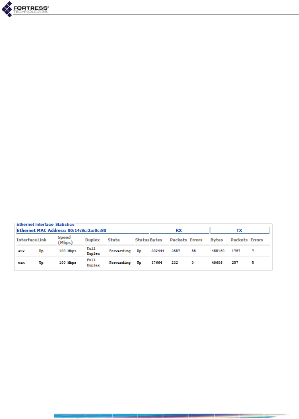
Bridge GUI Guide: Monitoring
179
Bad Packets - malformed packet received (Packets can be
malformed for a number of reasons, such as version
incompatibility or a failed hash check.)
Bad Keys - bad key packets—malformed key exchange
packets
Bad Decrypted - key packets the Bridge was unable to
decrypt
5.6.2 Interface Statistics
Bridge interfaces displayed on the Monitor -> Statistics screen
are grouped by type.
Regardless of type, the Status of each interface can be: Up or
Down, and a common set of traffic statistics is shown for each
interface’s receive (RX) and transmit (TX) functions:
Bytes - the total number of bytes received/transmitted on
the interface
Packets - the total number of packets received/transmitted
on the interface
Errors - the total number of receive/transmit errors reported
on the interface
The Statistics screen provides additional information, according
to interface type.
5.6.2.1 Ethernet Interface Statistics
Figure 5.14.
Statistics
screen,
Ethernet Interface Statistics
frame, ES210, ES440, ES820
For each of the Bridge’s Ethernet interfaces, the Bridge
displays the Status and basic interface statistics described
above, as well as:
Link - displays whether the interface’s physical link is:
Up - successful data connection with a device attached
to that port
Down - no data link with a device attached to the port, or
the port is disconnected
Negotiating or Resolved - transient states between a
physical connection being made to the port and a data
link being established (Up) or failing to be established
(Down)
Speed - displays the speed at which the interface is passing
traffic in megabits per second.
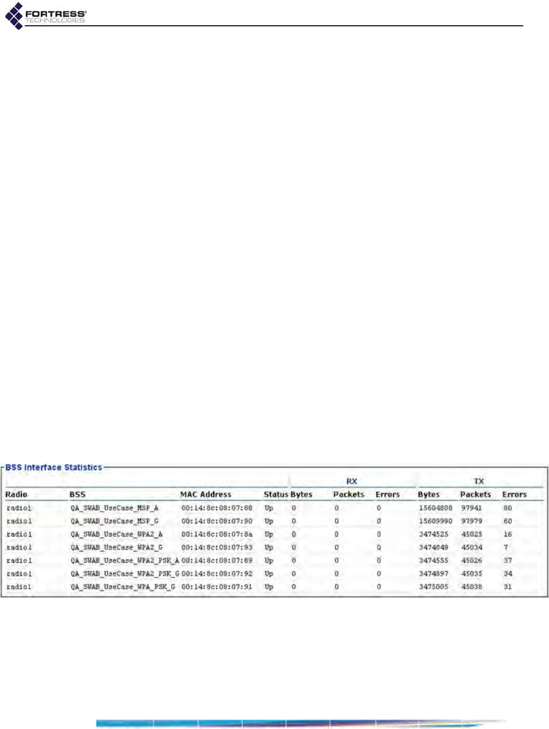
Bridge GUI Guide: Monitoring
180
Duplex - displays whether the device’s transmission mode
is Full Duplex or Half Duplex (or displays n/a if the duplex
setting does not apply.
State - the bridging status of the node from which the link is
made: Possible values and meanings depend on the
Bridge’s current Bridging Mode setting (Section 3.2):
When STP is used for bridging, possible values include:
Disabled - the interface is not passing traffic
Forwarding - the interface is passing all traffic
Listening - the interface is listening for BPDUs
(Bridge Protocol Data Units) in order to build its
loop-free path, but is not yet forwarding general
data frames
Blocking - the interface is blocking user traffic
(usually because it is a duplicate or sub-optimal
path)
When FastPath Mesh is used for bridging, possible
values include:
Disabled - the interface is not passing traffic
Forwarding All - the interface is passing all traffic
Blocking - the interface is blocking all traffic
Above these statistics, the Bridge displays the global
Ethernet MAC Address.
5.6.2.2 BSS Interface Statistics
On Bridges equipped with one or more radios (refer to Table
1.1 on page 3), the Bridge displays the Status and basic
interface statistics (described in Section 5.3.2) for any Basic
Service Sets (BSSs) configured on its radio(s).
Figure 5.15.
Statistics
screen,
BSS Interface Statistics
frame, all radio-equipped platforms
BSSs that are acting as access points (i.e., those that do not
have bridging enabled) are shown in their own frame with this
additional information:
Radio - the radio on which the BSS is configured
BSS - the name configured for the BSS (Section 3.3.4.1)

Bridge GUI Guide: Monitoring
181
MAC Address - the Media Access Control address of the
virtual interface the BSS provides
5.6.2.3 Bridge Link Interface Statistics
BSSs that are acting as nodes in a mesh network of Fortress
Bridges (i.e., those performing a network bridging function) are
shown in their own frame.
Figure 5.16.
Statistics
screen,
Bridge Link Interface Statistics
frame, all radio-equipped platforms
In addition to the Status and basic interface statistics
(described in Section 5.3.2), the Bridge displays this additional
information for bridging links:
Radio - the radio internal to the Bridge on which the MRP
BSS is configured
MAC Address - the Media Access Control address of the
virtual interface the BSS provides
State - the bridging status of the node from which the link is
made: Possible values and meanings depend on the
Bridge’s current Bridging Mode setting (Section 3.2):
When STP is used for bridging, possible values include:
Disabled - the interface is not passing traffic
Forwarding - the interface is passing all traffic
Listening - the interface is listening for BPDUs
(Bridge Protocol Data Units) in order to build its
loop-free path, but is not yet forwarding general
data frames
Blocking - the interface is blocking user traffic
(usually because it is a duplicate or sub-optimal
path)
When FastPath Mesh is used for bridging, possible
values include:
Disabled - the interface is not passing traffic
Forwarding All - the interface is passing all traffic
Blocking - the interface is blocking all traffic

Bridge GUI Guide: Monitoring
182
5.6.3 VLAN Statistics
The Bridge tracks VLAN traffic and displays the information, by
VLAN ID, for each configured VLAN ID, in Monitoring ->
Statistics -> VLAN Statistics.
Figure 5.17.
Statistics
screen,
VLAN Statistics
frame, all platforms
For each of packets received (RX) and packets sent (TX) on
each VLAN configured on the Bridge, the screen displays:
Clear - unencrypted packets received/sent
Encrypted - encrypted packets received/sent
Config. - configuration packets received/sent
Key Exch. - key exchange packets received/sent
In addition, for packets received (RX), under VLAN Mgmt., the
number of VLAN management packets received on the VLAN
are shown.
5.7 IPsec SAs Monitoring
The Security Associations established between the Bridge and
its IPsec peers are displayed on Monitor -> IPsec Status.
Except for the Remaining Time countdown, Inbound SPI and
Outbound SPI (Security Parameter Index), the parameters
shown here are configured, globally or per SPD (Security
Policy Database) entry, with the settings accessed through
Configure -> IPsec (refer to Section 4.2).
NOTE: If both data
and time limits are
configured, an SA will
expire at whichever
comes first, potentially
when Remaining Time
still shows a positive
value.
Lifetime KB - optionally, a limit on the amount of data an
SA can pass before being deleted can be globally set, in
kilobytes, and the value displayed on IPsec Status. The
default global setting configures no data limit for SAs, as
indicated by the displayed value: unlimited.
Remaining Time and Lifetime Seconds - a global SA time
limit can also be specified and the value displayed on IPsec
Status, in seconds, for all SAs present. The Remaining Time
displayed is a countdown from this value, also in seconds.
Local Address and Local Mask - identify the subnet of local
IP addresses defined in the SPD entry used by the SA (the
outbound source subnet or inbound destination subnet).
Inbound SPI and Outbound SPI - the 32-bit Security
Parameter Index included in an IPsec packet, together with
the destination IP address and IPsec protocol, uniquely
identifies the SA. SPIs are pseudorandomly derived during
IKE transactions.
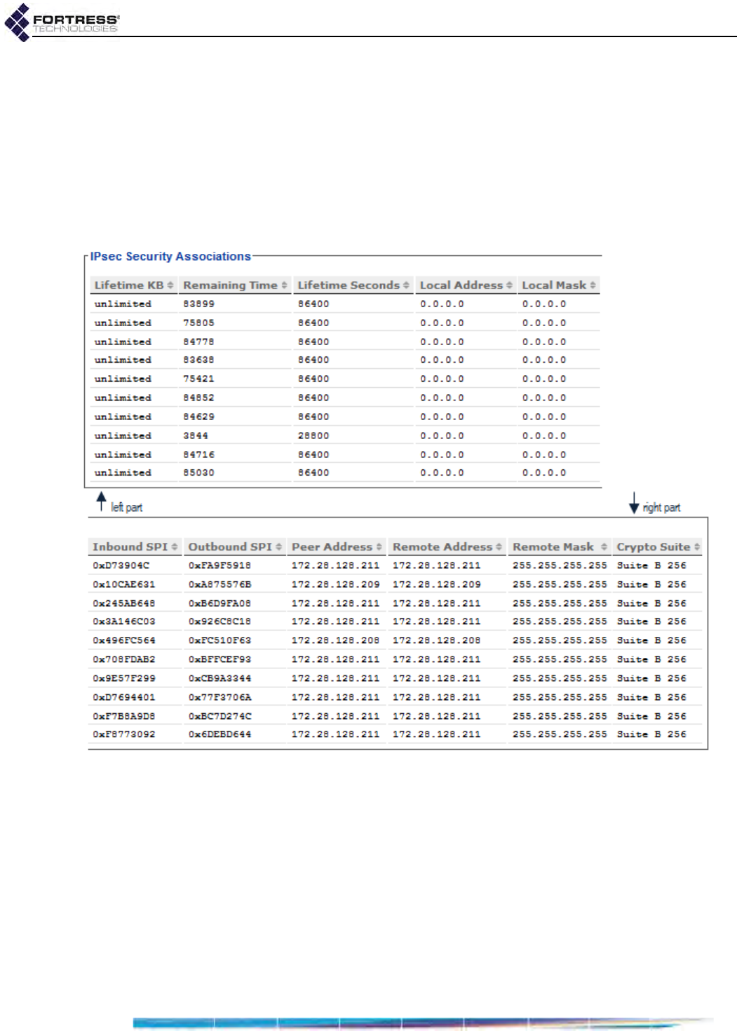
Bridge GUI Guide: Monitoring
183
Peer Address - identifies the remote IPsec peer participating
in the SA by IP address.
Remote Address and Remote Mask - identify the subnet of
remote IP addresses defined in the SPD entry used by the
SA (the inbound source subnet or outbound destination
subnet).
Crypto Suite - shows the cryptographic algorithm suite in
use by the SA.
Figure 5.18.
IPsec Status
screen, all platforms
5.8 FastPath Mesh Monitoring
When FastPath Mesh is licensed (Section 6.3) and enabled
(Section 3.2.1), the Bridge GUI provides an array of information
on the configuration, composition and operation of the FP
Mesh network on Monitor -> Mesh Status.
5.8.1 FastPath Mesh Bridging Configuration
The settings configured on Configure -> Administration ->
Bridging Configuration and/or Configure -> FastPath Mesh ->
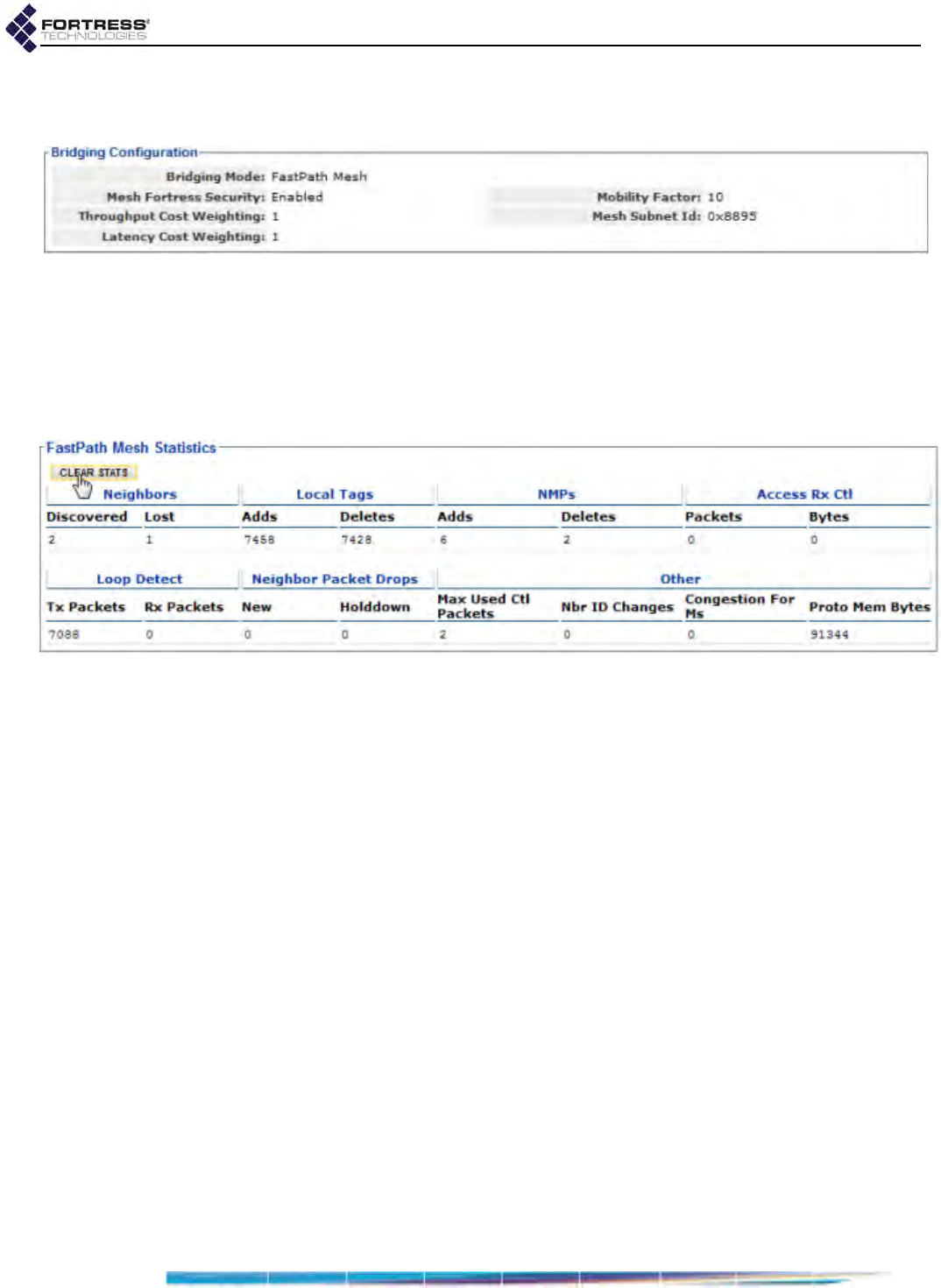
Bridge GUI Guide: Monitoring
184
Global Settings are displayed in the Bridging Configuration frame
and described in detail in sections 3.2.1.1 through 3.2.1.5.
Figure 5.19.
Mesh Status
screen,
Bridging Configuration
frame, all platforms
5.8.2 FastPath Mesh Statistics
When FP Mesh is licensed and enabled, the Fortress Bridge
gathers statistics on mesh network operations for display in the
FastPath Mesh Statistics frame.
Statistics can be cleared manually (see below) or by a reboot.
Figure 5.20.
Mesh Status
screen,
FastPath Mesh Statistics
frame, all platforms
Neighbors - are other FP Mesh network Mesh Points (MPs)
directly linked to the current MP (refer to Section 3.2.1).
Discovered - a count of MP nodes that have linked
directly to one of the current MP’s FP Mesh Core
interfaces since Statistics were last cleared
Lost - a count of neighbors (above) whose connection
to the current MP has been lost since Statistics were
last cleared, because they have moved to a more
remote location relative to the current MP or have left
the network.
A neighbor can also be “bounced” into a Lost state and then
back to a Discovered state, due to a temporary deterioration
of its link to the current MP, followed by the link’s
restoration.
Local Tags - are non-routing control information in FP Mesh
protocol packets provided by the local MP for distribution to
network peers since Statistics were last cleared.
Adds - the number of tags added by the current MP
Deletes - the number of tags deleted by the current MP
NMPs - are control information pertaining to NMPs inserted
into FP Mesh protocol packets by network peers and

Bridge GUI Guide: Monitoring
185
received by the current MP since Statistics were last
cleared.
Adds - NMP information added by network peers
Deletes - NMP information deleted by network peers
CAUTION: Non-
zero counts for Ac-
cess Rx are caused by an
FP Mesh bridging link
on the current MP being
incorrectly configured
as an Access, rather
than as a Core interface.
Access Rx Ctl - count of the number of FP Mesh control
packets received on the current MP’s Access interfaces
(refer to Section 3.2.1) since Statistics were last cleared. In
a correctly configured FP Mesh network these counts
should always be 0 (zero).
Packets - total number of packets received
Bytes - total number of bytes received
Loop Detect - counts loop detection protocol packets since
Statistics were last cleared.
Tx Packets - the number of loop detection packets
transmitted by the current Bridge
Rx Packets - the number of loop detection packets
received by the current Bridged
Neighbor Packet Drops - counts FP Mesh routing protocol
packets dropped by the current Bridge since Statistics were
last cleared.
New - the number of routing protocol packets received
from new neighbors and dropped because of
congestion
Holddown - the number of routing protocol packets
received from unstable neighbors and therefore
dropped
Other - displays additional statistical information.
Max Used Ctl Packets - maximum FP Mesh control
packets received in a single 250-millisecond interval, up
to a maximum measurable count of 30, indicating how
busy the FP Mesh network is.
Nbr ID Changes - counts the number of times the
current MP has detected a change in the routing
protocol identifier of a neighbor since Statistics were last
cleared.
Congestion for Ms - shows current measure of the
length of time in milliseconds that the current MP will
remain in congested mode while processing routing
control packets.
Proto. Mem. Bytes - protocol memory bytes, shows
current measure of the amount of Bridge memory used
by the FP Mesh routing protocol.
Clear the Bridge’s record of FastPath Mesh statistics by
clicking CLEAR STATS in the upper right of the screen.
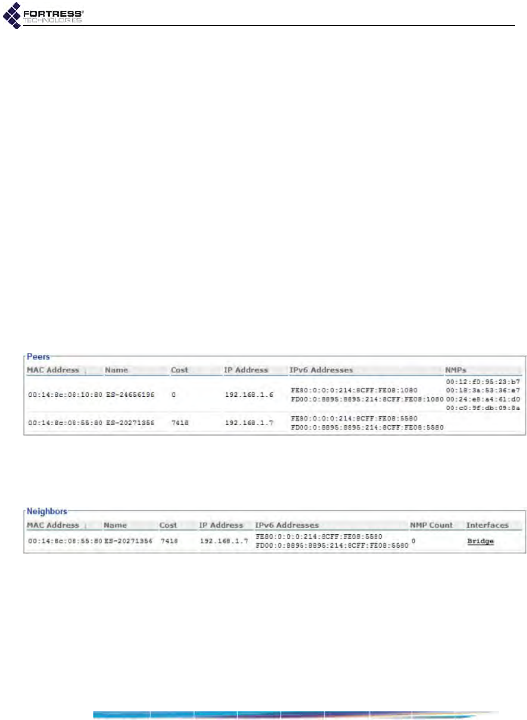
Bridge GUI Guide: Monitoring
186
5.8.3 FastPath Mesh Peers and Neighbors
All MP nodes on the FP Mesh network, including the current
MP, are shown in the Peers frame of the Mesh Status screen.
MPs directly connected to the current MP are shown in
Neighbors.
For each MP of either type the Bridge GUI displays:
MAC Address - the MP’s Media Access Control address
Name - the MP’s hostname
Cost - the lowest cost associated in FP Mesh of reaching
the remote MP from the current MP
Path cost is additive by hops. The current Bridge has a
constant Cost of 0 (zero). Wired interfaces cost much less
than wireless. A Cost of 4,294,967,295 is “infinite”: the MP is
unreachable, a transient condition just before the MP
leaves the list. The greater the cost to a peer, the less
preferred is any route to or through that peer.
IP Address - the IPv4 address of the MP
IPv6 Addresses - all IPv6 addresses of the MP, including the
link local address, the RFC-4193 unique local address, and
any other user-configured or auto-configured global
addresses.
Figure 5.21.
Mesh Status
screen,
Peers
frame, all platforms
For each MP listed on Peers, under NMPs, the MAC addresses
of any connected Non-Mesh Points (devices on the peer MP’s
Access interface[s]) are shown.
Figure 5.22.
Mesh Status
screen,
Neighbors
frame, all platforms
For each of the current MP’s Neighbors, the number of
connected NMPs is displayed under NMP Count, followed by
the Interfaces over which the current MP is connected to the
neighbor. An MP can be connected to a neighbor over multiple
interfaces.
5.8.4 Multicast/Broadcast Forwarding
The three values that FP Mesh takes into account when
making multicast forwarding decisions—destination, source
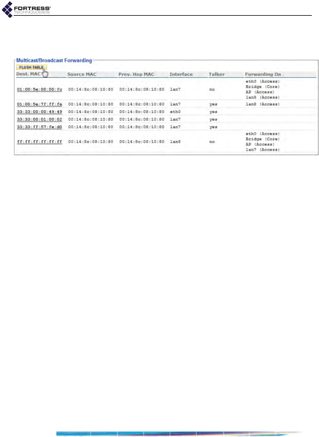
Bridge GUI Guide: Monitoring
187
and previous hop—are shown in the first three columns of the
Multicast/Broadcast Forwarding frame, along with local interface
and mode information.
Figure 5.23.
Mesh Status
screen,
Multicast/Broadcast Forwarding
frame, all platforms
Dest. MAC - the destination MAC address of the multicast
Source MAC - the MAC address of the MP from which the
multicast originated (The actual source may be an NMP
behind the MP.)
Prev. Hop MAC - the MAC address of the previous hop in
the multicast route
Interface - the interface on which the multicast is received, if
it is an Access interface (Core interfaces show N/A, not
applicable.)
Talker - whether the current MP is a sender for the
destination MAC address (yes) or only a listener (no)
An MP becomes a talker for a multicast group when it
receives a packet from a sender on one of the MP’s FP
Mesh Access interfaces, or when the MP is manually
configured as a Talker (refer to Section 3.2.1.7). MPs do not
show up as talkers on broadcast flows, even though the
broadcast source may be on one of the MP’s Access
interfaces.
Forwarding On - the interfaces on which the multicast on
this route is forwarded.
Clear the Bridge’s Multicast/Broadcast Forwarding information
by clicking FLUSH TABLE in the upper right of the screen.
5.8.5 FastPath Mesh Multicast Groups
A FastPath MP automatically subscribes to and leaves
multicast groups on behalf of NMPs by snooping IP multicast
control messages on FP Mesh Access interfaces. You can also
establish multicast stream subscriptions manually (refer to
Section 3.2.1.7). Regardless of how they were established,
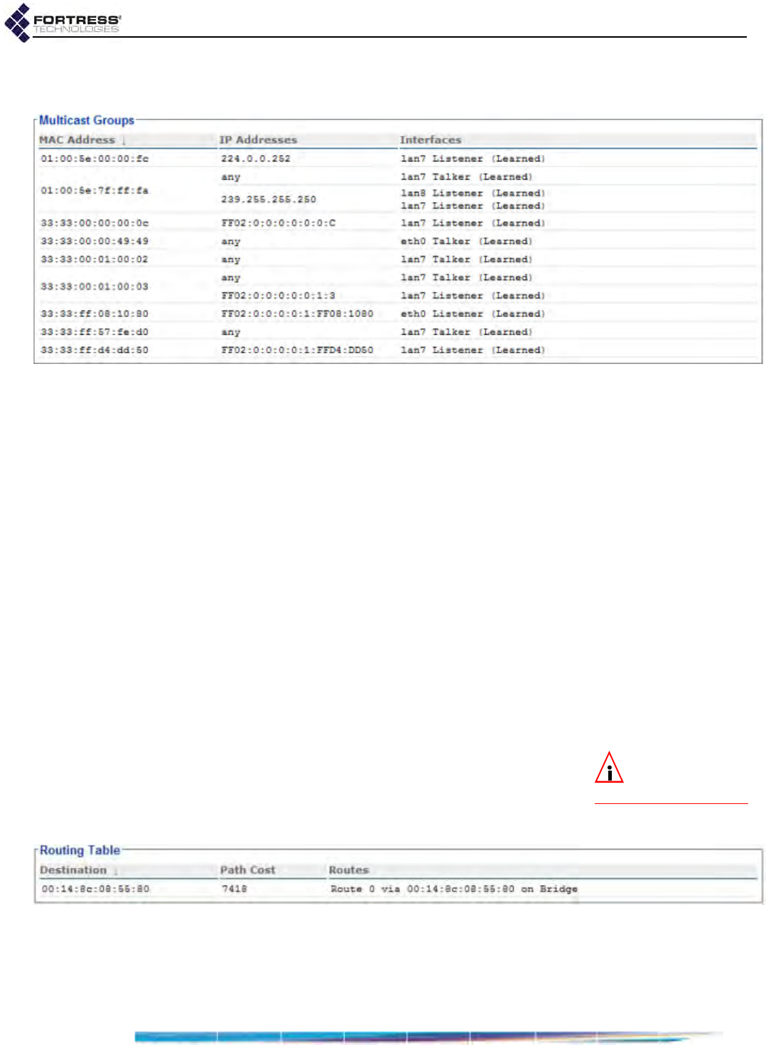
Bridge GUI Guide: Monitoring
188
current multicast subscriptions are shown in the Multicast
Groups frame.
Figure 5.24.
Mesh Status
screen,
Multicast Groups
frame, all platforms
MAC Address - the MAC address of the multicast stream
IP Addresses - the addresses of IP multicast groups the MP
is currently subscribed to that map to this MAC address
Interfaces - FP Mesh Access interfaces on the current MP
that are subscribed to this multicast, identifying the
subscription mode as:
Listener - receives multicast packets
Talker - sends multicast packets
Both - receives and sends
In parentheses, Interfaces also shows whether the group
was Learned from IGMP (as a listener) or incoming data
packet (as a talker), or whether the group was manually
Configured.
Manually subscribing to multicast groups is described in
Section 3.2.1.7.
5.8.6 FastPath Mesh Routing Table
NOTE: The Routing
Table shows only
routes to other MPs.
FP Mesh computes and records many routes to a given
destination. While only the lowest cost route among these is
stored in the forwarding table and used to forward traffic, all
computed routes are shown in the Routing Table frame on the
Mesh Status screen.
Figure 5.25.
Mesh Status
screen,
Routing Table
frame, all platforms
Destination - MAC address of the destination MP
Path Cost - the lowest cost associated in FP Mesh of
reaching the remote MP from the current MP (Paths are
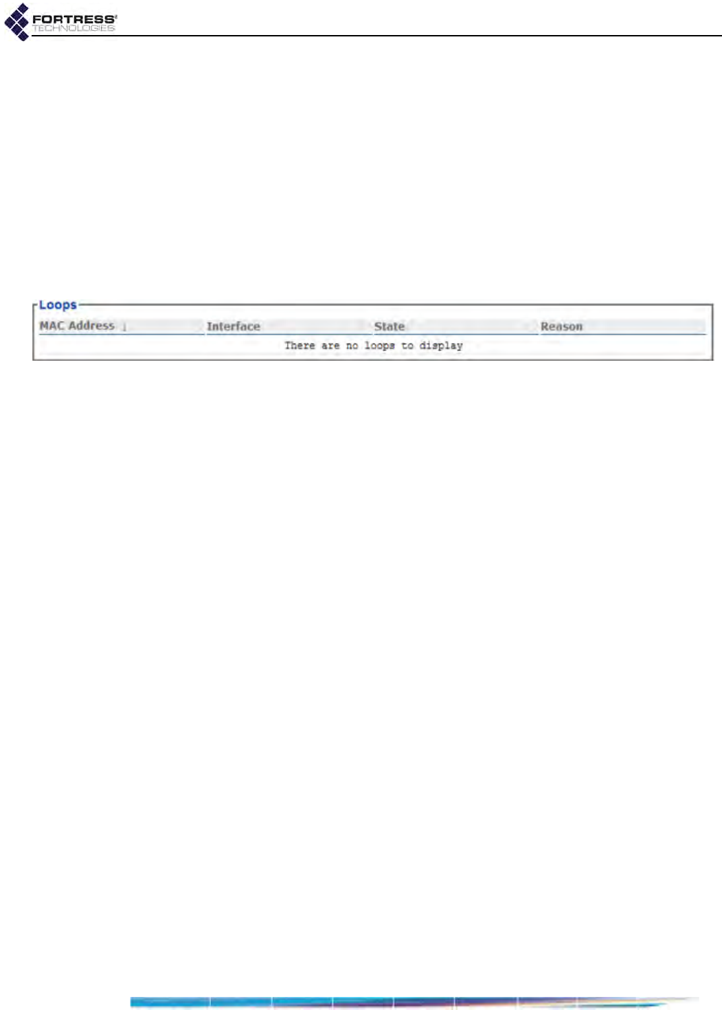
Bridge GUI Guide: Monitoring
189
listed in ascending order of cost, with the lowest cost path
listed first.)
Routes - possible routes to the destination MP in
descending order of preference
5.8.7 FastPath Mesh Loops
FP Mesh prevents bridging loops from forming on Core
interfaces, which connect MPs to one another. A network loop
can form, however, when MPs can also detect one another on
their FP Mesh Access interfaces. If such a loop exists on the
network, it is displayed in the Mesh Status screen’s Loops
frame.
Figure 5.26.
Mesh Status
screen,
Loops
frame, all platforms
Review the network topology to make sure that the
connections causing the loops are intentional (for purposes of
redundancy) rather than accidental.
MAC Address - the MAC address of the Mesh Point
detected by the current MP on an FP Mesh Access
interface
Interface - the FP Mesh Access interface on which the
network MP is detected
State - whether that interface is blocking, forwarding or
disabled
Reason - why the interface is the current State (above)
5.9 System Log Monitoring
The Bridge logs significant system activity and status
information.
Access the log by clicking Monitor -> System Log.
If you log on to a Log Viewer-level account, the Bridge GUI
opens on the System Log screen. Administrator- and
Maintenance-level administrators can view the entire log, while
Log Viewer-level administrators can view only non-
configuration events.
Each activity item is date-and-time stamped, its severity is
indicated and a brief text description is given. Among other
information, the log records:
FIPS self-test runs and results
when Secure Clients contact and negotiate keys with the
Bridge
system configuration changes
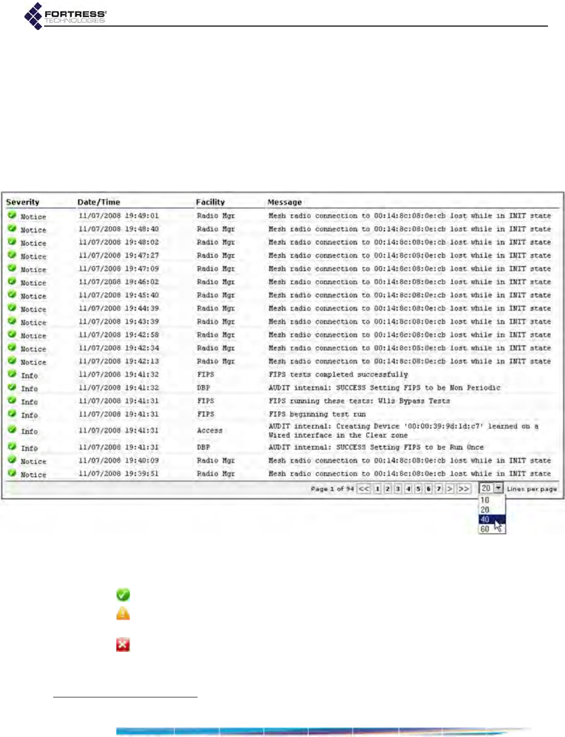
Bridge GUI Guide: Monitoring
190
when the cryptographic processor is restarted
system and communication errors
when FP Mesh neighbors are discovered and lost (when
Fortress’s FastPath Mesh is licensed and enabled)
The log is allocated 256 Kbytes of memory and can contain a
maximum of approximately 2,000 log messages (approximate
because record sizes vary somewhat). When the log is full, the
oldest records are overwritten as new messages are added to
the log.
Figure 5.27.
System Log
screen, all platforms12
The Bridge’s three status icons indicate the severity of System
Log messages:
Notice or Info - message is purely informational
Warning - unexpected event may indicate a problem/require
attention
Error - failure or attempted breach requires attention
You can use the controls at the lower right of the screen to
page through the log and specify the number of messages
shown per page: 10, 20, 40 or 60.
12.Radio-associated messages absent when no internal radio is present (refer to Table 1.1 on page 3).

Bridge GUI Guide: Monitoring
191
When remote audit logging is enabled (Section 4.6.1), log
messages sent to the external audit log are identified as AUDIT
messages. Internally generated audit events are flagged
AUDIT internal. Audit events generated by administrative action
additionally identify the account and interface the administrator
was logged onto at the time of the event.

Bridge GUI Guide: Maintenance
192
Chapter 6
System and Network Maintenance
The Bridge GUI provides access to a number of administrative
and diagnostic functions under Maintenance on the main menu.
Only Bridge GUI Advanced View displays the Licensing link.
6.1 System Maintenance
The administrative functions you can access through Maintain
-> System vary according to whether you are in Bridge GUI
Simple View or Advanced View, as shown in Table 6.1
6.1.1 Resetting Connections
You can reset all of the Bridge’s network connections, forcing
users and devices to rekey and reauthenticate.
If Cached Auth. Credentials is Disabled users are prompted to
re-enter their user names and passwords in order to re-
establish their network connections. If Allow Cached Credentials
is Enabled (the default) locally authenticated users are
reauthenticated transparently, using their cached user
credentials (Section 4.1.13).
Resetting connections can be useful after network
reconfiguration, as part of a diagnostic procedure, or if an
expected device is missing from the network.
Table 6.1. System Maintenance Functions
Simple & Advanced Views Advanced View Only
Version Reset Clients
Restart Controller Device FIPS Retest
Upgrade Controller Device Reset to Factory Defaults
Backup System Settings
Restore System Settings
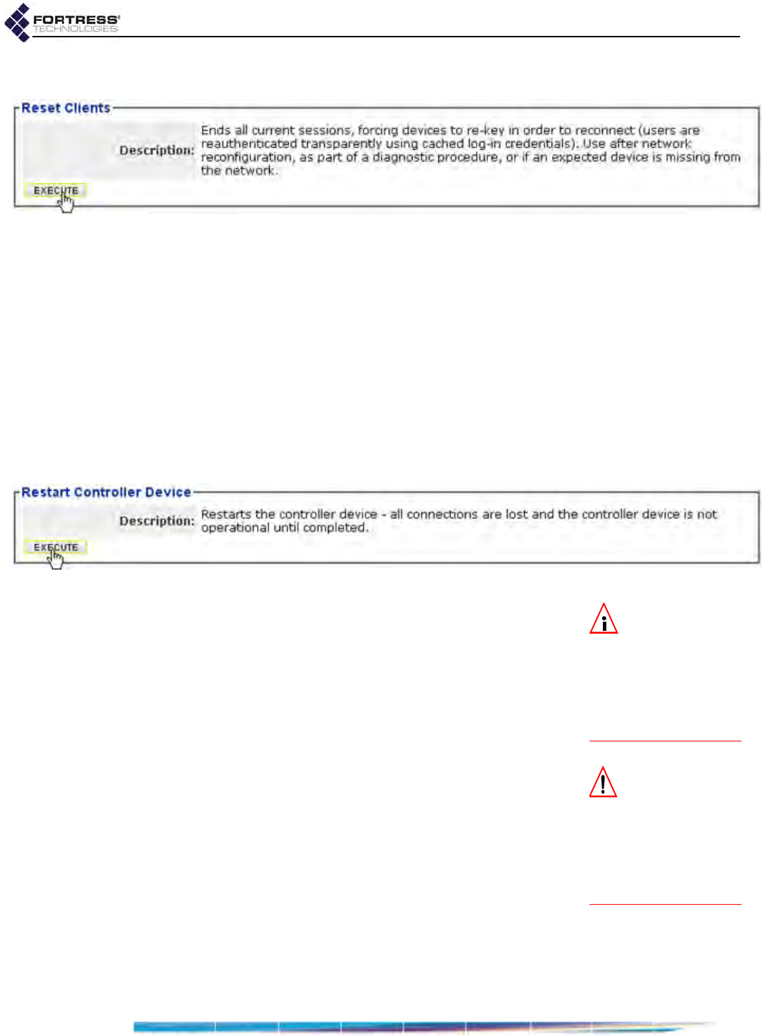
Bridge GUI Guide: Maintenance
193
You can reset sessions only in Advanced View.
Figure 6.1. Advanced View
Reset Clients
frame, all platforms
To reset connections:
1Log on to the Bridge GUI through an Administrator-level or
Maintenance-level account and select ADVANCED VIEW in the
upper right corner of the page, then Maintain -> System from
the menu on the left.
2In the System screen’s Reset Clients frame, click EXECUTE.
6.1.2 Rebooting the Bridge
The reboot option power cycles the Bridge, ending all sessions
and forcing Secure Client devices (and any other Fortress
Bridges) in communication with the Bridge to re-key in order to
start a new session.
Figure 6.2.
Restart Controller Device
frame, all platforms
NOTE: You can
also reboot the
Bridge with chassis con-
trols (refer to the appro-
priate Hardware Guide)
or from the Bridge CLI
(refer to the CLI Soft-
ware Guide).
To reboot the Bridge:
1Log on to the Bridge GUI through an Administrator-level or
Maintenance-level account and select Maintain -> System
from the menu on the left.
1In the System screen’s Restart Controller Device frame, click
EXECUTE.
CAUTION: When
in blackout mode,
some model Bridges
still exhibits a single,
initial blink of less than
half a second, at the be-
ginning of the boot pro-
cess.
2A dialog asks you to confirm your intention: click OK.
The Bridge GUI displays Restarting the controller device -
please be patient. Bridge chassis LEDs go dark, then signal
the boot process, and finally resume normal operation
(refer to the Fortress Hardware Guide for your Bridge model
for more detail).
6.1.3 Viewing the Software Version
To view the software version currently running on the Bridge,
log on to the Bridge GUI through an Administrator-level account
and from the menu on the left, select: Maintain -> System, and
refer to Currently Running in the Version frame.
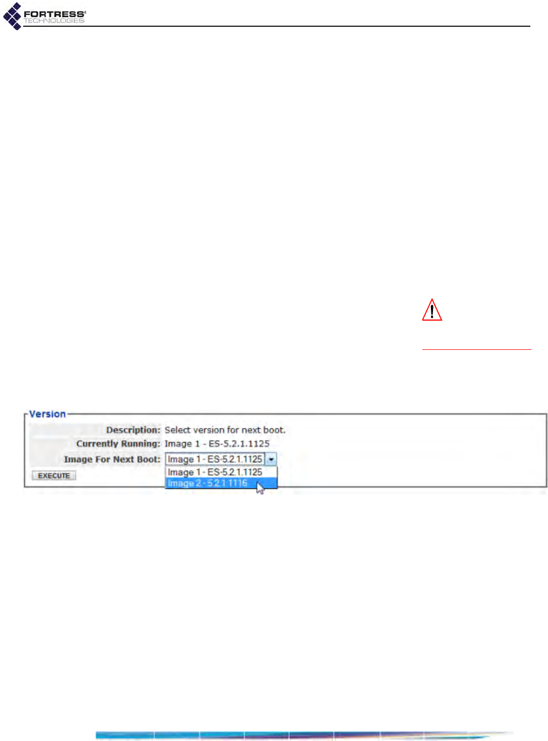
Bridge GUI Guide: Maintenance
194
6.1.4 Booting Selectable Software Images
The Bridge stores two, user-selectable copies (or images) of
the Bridge software on separate partitions of the internal flash
memory.
When the Bridge’s software is upgraded (Section 6.1.5), the
new software is first written to the non-running boot partition,
overwriting any version stored there. When the Bridge is
rebooted to complete the upgrade process, it boots from the
partition to which the upgrade was downloaded, with the same
configuration settings that were in effect before the upgrade
procedure.
The Bridge then defaults to the boot partition with the latest
software image—the last image booted—whenever it restarts.
New configuration changes are not written to the non-running
boot partition. If you boot from the non-running boot partition,
configuration settings will return to those in effect at the time
the Bridge’s software was last upgraded.
CAUTION: If Image
for Next Boot indi-
cates INVALID, do not se-
lect it or click EXECUTE.
To select the next boot image:
1Log on to the Bridge GUI through an Administrator-level
account and select Maintain -> System from the menu on
the left.
2In the System screen’s Version frame, in Image for Next
Boot, select the next image to boot from the dropdown.
3Click EXECUTE.
Figure 6.3.
Version
frame, all platforms
The next time the Bridge boots, it will boot the specified image.
6.1.5 Upgrading Bridge Software
Fortress Technologies regularly releases updated versions of
Fortress Bridge software to add new features, improve
functionality and/or fix known bugs. Upgrade files may be
shipped to you on CD-ROM or, more often, made available for
downloading from your account on www.fortresstech.com.
Fortress Secure Clients are backward compatible with Bridge
software. It is nonetheless recommended that the Secure
Clients of the Bridge be upgraded to the most recent version of
the Secure Client software available for their respective
platforms.
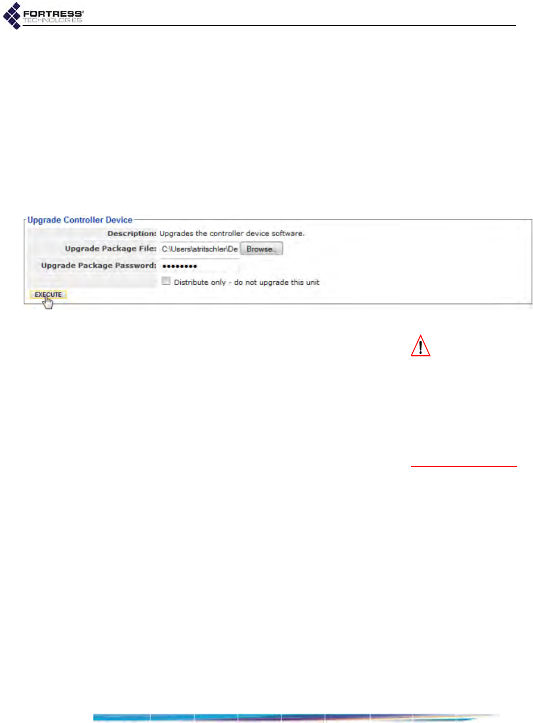
Bridge GUI Guide: Maintenance
195
The Bridge flash memory is partitioned into two, bootable
image areas. The software upgrade file is written to the non-
running partition—i.e., the partition that does not contain the
software currently running on the Bridge. The upgrade does
not therefore take effect until the Bridge is rebooted (as
described in Section 6.1.2), and the currently running software
is retained on the partition it was originally written to.
The software image on a given flash partition cannot be
downgraded, and you should not overwrite an image with an
earlier version of the software. You can, however, revert to the
earlier version of the software even after you have upgraded
and rebooted the Bridge (refer to Section 6.1.2).
Figure 6.4.
Upgrade Controller Device
frame, all platforms
CAUTION: If you
have problems af-
ter successfully booting
from the upgraded par-
tition, do not retry the up-
grade while the Bridge is
still running the newer
software. Revert to the
previous software ver-
sion before retrying the
upgrade.
To upgrade Bridge software:
1Log on to the Bridge GUI through an Administrator-level
account and select Maintain -> System from the menu on
the left.
2In the System screen’s Upgrade Controller Device frame:
Click to Browse to the location of the Bridge upgrade file
and select it for upload.
Enter the Upgrade Package Password : fortress
Ensure that the Distribute only - do not upgrade this unit
box is not selected (the default).
The Distribute only - do not upgrade this unit checkbox is
intended to be used in conjunction with the Bridge’s Auto-
Config function, as are the Upgrade using stored file
checkbox and DELETE STORED FILE button that will be
present if an upgrade file has been uploaded for
distribution. These controls should not be used during
standard upgrade procedures; refer to the Auto Config
Software Guide for more information.
3Click EXECUTE. The Upgrade Status dialog displays the
name of the upgrade package, notes approximately how
long the upgrade process will take, and provides dynamic
Upgrade Status and Upgrade Operation information.
Operations display in order: Starting, Uploading, Preparing,
Loading, Decrypting, Checking Signature, Validating,
Unpacking, Installing, and finally, Finished. Depending on

Bridge GUI Guide: Maintenance
196
how quickly each completes, you may not see every
operation.
When upgrade operations are Finished, the dialog Note
instructs you to restart the controller device to activate the
newly upgraded software image.
4Click to CLOSE the Upgrade Status dialog.
The Version frame on the System screen shows the non-
running image number as the Image for Next Boot.
5In the System screen’s Restart Controller Device frame, click
EXECUTE.
The status line at the top of the screen advises: Restarting
the controller device - please be patient. You will have to log
back on after the Bridge reboots.
After the upgrade, the Bridge defaults to the boot partition with
the latest software image—the last image booted—whenever it
restarts.
If you experience problems after rebooting, revert to the
previous Bridge software version (below) and then retry the
upgrade.
NOTE: Configura-
tion changes are
written only to the run-
ning boot partition. If
you boot from the non-
running boot partition,
settings will revert to
those in effect at the
time the Bridge’s soft-
ware was last upgraded.
To revert to the previous software version:
Because it is not overwritten, the software version the Bridge
was running before the upgrade remains available in the event
of a problem with the newer version of the software.
1Log on to the Bridge GUI through an Administrator-level
account and select Maintain -> System from the menu on
the left.
2In the System screen’s Version frame, in Image for Next
Boot, select the non-running image of the software version
in effect before you upgraded from the dropdown.
3Click EXECUTE.
4In the same screen’s Restart Controller Device frame, click
EXECUTE.
The status line at the top of the screen advises: Restarting
the controller device - please be patient. You will have to log
back on after the Bridge reboots.
6.1.6 Backing Up and Restoring
The backup/restore function of the Bridge creates and
downloads a configuration file that can be used to restore the
settings it saves. You can create multiple backup files under
pathnames of your choosing.
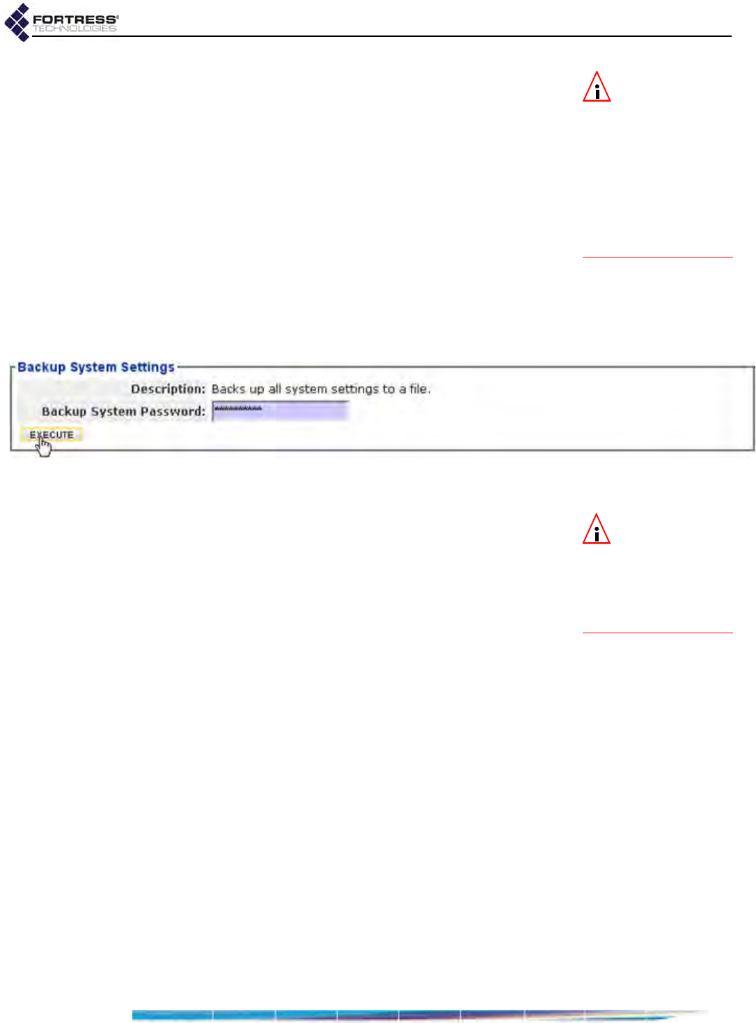
Bridge GUI Guide: Maintenance
197
NOTE: The back-
up file used to re-
store the Bridge con-
figuration must have
been made on the cur-
rent or another Bridge
of the same model. You
cannot restore from a
backup file created on a
different Fortress Bridge
model.
Most Bridge configuration settings are saved to the backup file.
The only exceptions are the Bridge’s System Time and System
Date settings (Configure -> Administration -> Time
Configuration). When you restore from the backup file, the rest
of the settings in the current configuration are overwritten by
those in the backup file.
Fortress Technologies recommends backing up the Bridge
configuration:
when the Bridge is first set up
immediately before configuration changes are made
after changes are made and the new configuration has
been tested and proved fully operational
You can also use the restore function to reconfigure a Bridge
using a backup file created on a different Bridge.
Figure 6.5.
Backup System Settings
frame, all platforms
To back up the Bridge configuration:
NOTE: Backup file
passwords must
be a minimum of ten al-
phanumeric characters.
Strong passwords con-
tain a mix of upper and
lower cases.
1Log on to the Bridge GUI through an Administrator-level
account and select Maintain -> System from the menu on
the left.
2In the System screen’s Backup System Settings frame,
optionally enter a Backup System Password, or leave the
field empty to apply a default password. You do not need to
know the default password to restore from a file that uses it.
Leave the password field empty during the restore
operation, and the default will again be applied
transparently.
If you created a non-default password for the backup file,
record it in a secure place; you will need it to restore from
the backup file.
3Click EXECUTE. The standard browser dialog asks whether
you want to open or save the file (if the .cfg file type is not
yet associated with an application, IE7 presents options to
find or save it). Save the file with the name and in the
location of your choice.
The default backup filename is configuration-backup.cfg.
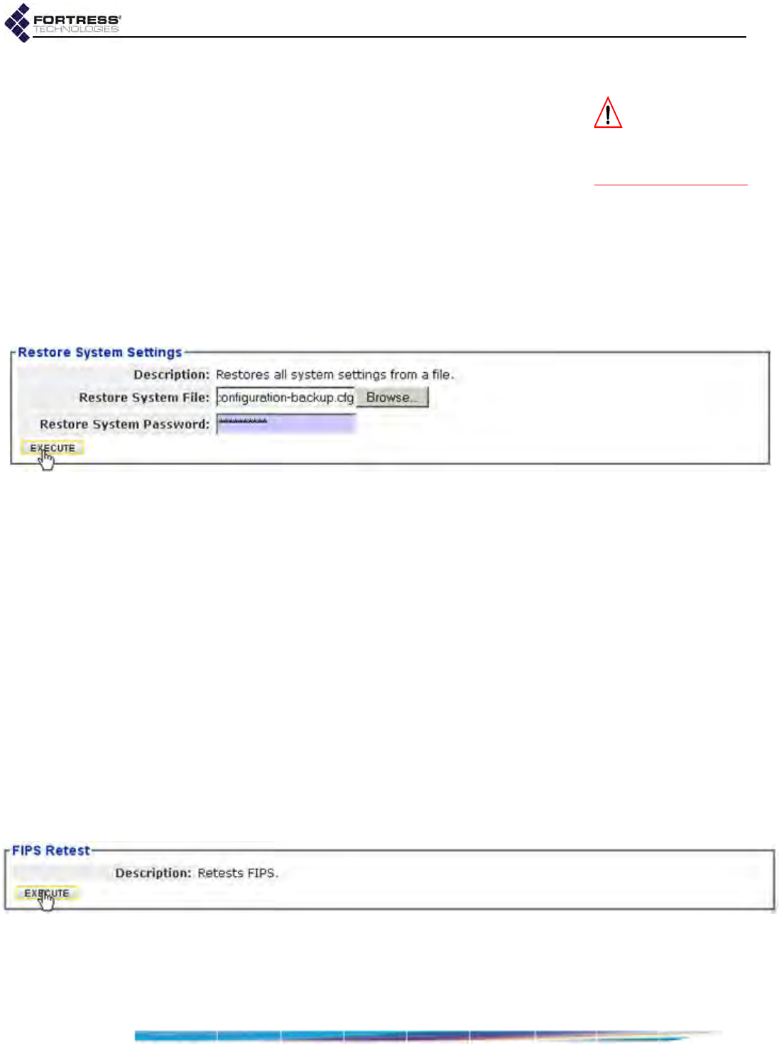
Bridge GUI Guide: Maintenance
198
To restore the Bridge configuration from a backup file:
CAUTION: The re-
store operation
overwrites existing set-
tings with those in the
backup file.
1Log on to the Bridge GUI through an Administrator-level
account and select Maintain -> System from the menu on
the left.
2In the System screen’s Restore System Settings frame, in
Restore System File, enter the pathname or browse to the
location of the Bridge backup configuration file.
3In the same frame, enter the Restore System Password (the
Backup System Password from the backup procedure
above).
4Click EXECUTE. The Restore Status dialog displays the
progress of the restore operation and notifies you when it
has completed.
Figure 6.6.
Restore System Settings
frame, all platforms
5Click OK to close the dialog informing you that a reboot is
required to complete the restore procedure.
6In the same screen’s Restart Controller Device frame, click
EXECUTE.
6.1.7 Initiating FIPS Retests
You can manually initiate the same self-tests that the Bridge
runs automatically in accordance with FIPS 140-2, (Federal
Information Processing Standards’ Security Requirements for
Cryptographic Modules).
When the Bridge is in FIPS operating mode, it will shut down
and automatically reboot in the event of a FIPS self-test failure.
It will not resume normal operation until it has passed FIPS
power-on self-tests (refer to Section 4.1.1).
When in Normal (non-FIPS) operating mode, the Bridge logs
FIPS self-test failures, but continues to operate even if self-
tests fail.
Figure 6.7. Advanced View
FIPS Retest
frame, all platforms
You can initiate FIPS self tests only in Advanced View.
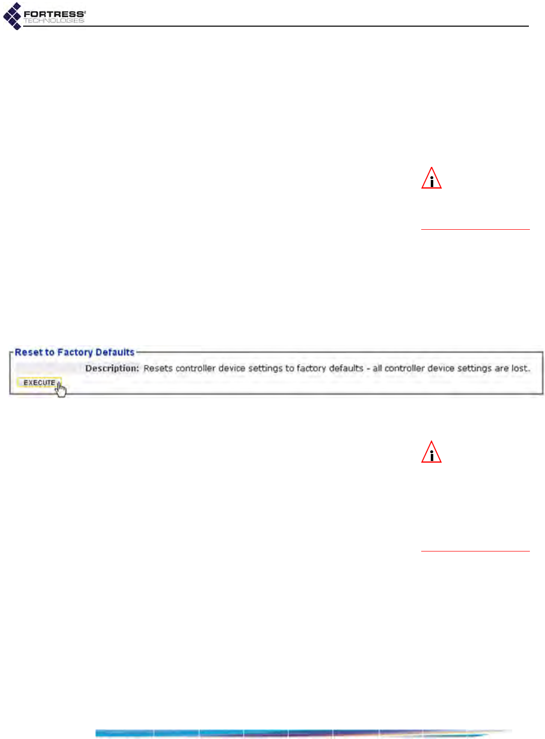
Bridge GUI Guide: Maintenance
199
To run FIPS tests manually:
1Log on to the Bridge GUI through an Administrator-level
account and select ADVANCED VIEW in the upper right corner
of the page, then Maintain -> System from the menu on the
left.
2In the System screen’s FIPS Retest frame, click EXECUTE.
6.1.8 Restoring Default Settings
NOTE:
Licensed
features are re-
tained even after the
Bridge
is reset to factory
defaults.
With the exceptions of any special features it has been
licensed to use, the Fortress Bridge’s factory default
configuration settings can be restored in their entirety.
Because the Bridge’s configuration settings could themselves
be sensitive, Fortress Technologies recommends restoring
them to their default values whenever the Bridge is to be
shipped (or otherwise transported) out of a secured location.
In order to fully restore the Bridge to its factory configuration
defaults, you must perform a separate restore operation for the
software image on each of the Bridge’s flash memory partitions
(refer to Section 6.1.4).
You can reset to factory defaults only in Advanced View.
Figure 6.8. Advanced View
Reset to Factory Defaults
frame, all platforms
To restore the factory default configuration:
NOTE: You can
also restore the
Bridge to its factory de-
fault settings with the
chassis controls (refer to
the appropriate Hard-
ware Guide) and from
the CLI (refer to the CLI
Software Guide).
1Log on to the Bridge GUI through an Administrator-level and
select ADVANCED VIEW in the upper right corner of the page,
then Maintain -> System from the menu on the left.
2In the System screen’s Reset to Factory Defaults frame click
EXECUTE.
3Click OK at the confirmation query.
At the top of the screen the GUI displays: Reset to Factory
Defaults - please be patient.
4Close your browser.
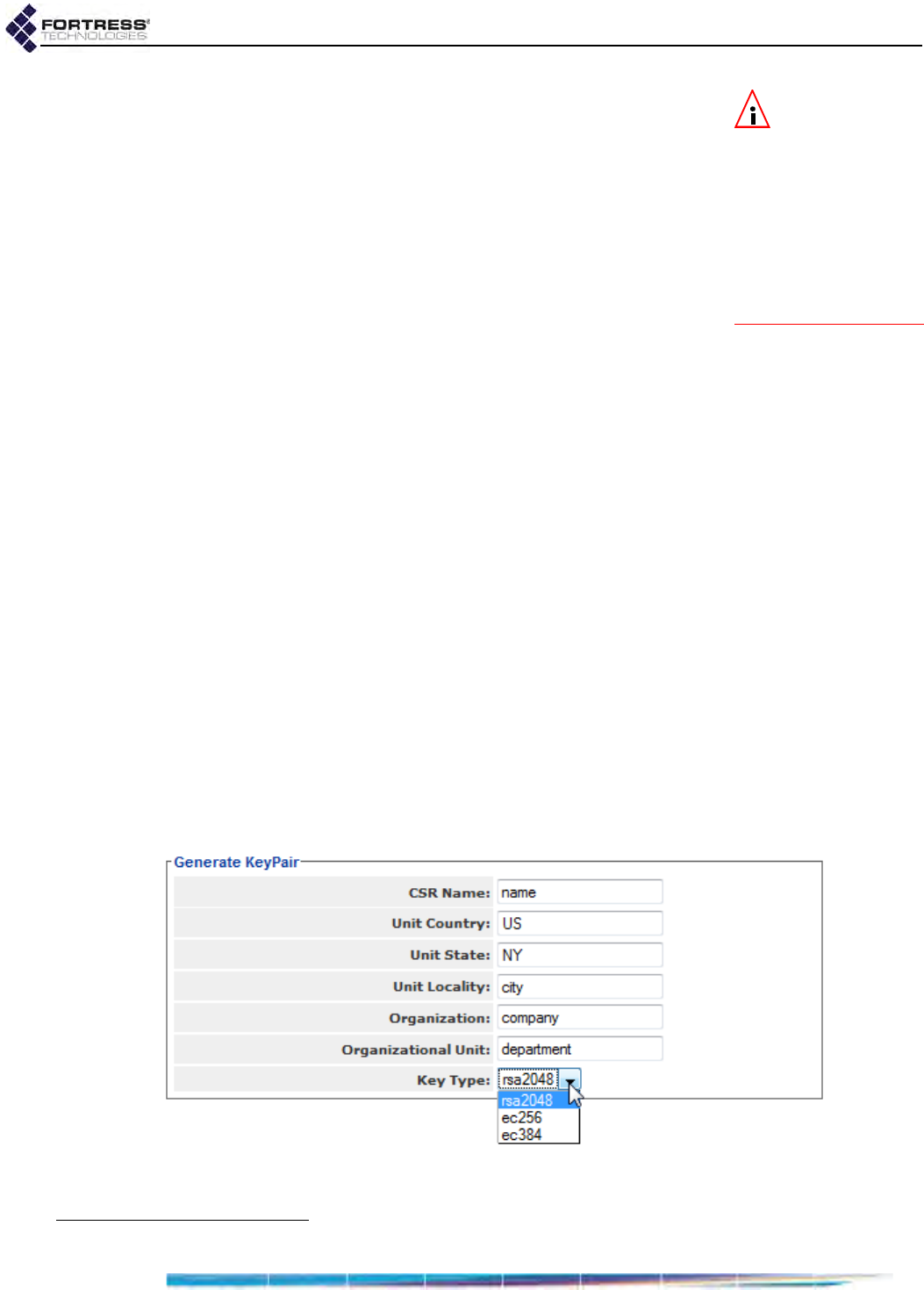
Bridge GUI Guide: Maintenance
200
NOTE: In order to
re-access a Bridge
at factory defaults, you
must use a new browser
instance on a computer
with a non-routed con-
nection to a clear inter-
face on the Bridge and
an IP address in the
same subnet as the
Bridge’s default address.
5If you want to restore the default configuration on both of
the Bridge’s flash memory partitions, reopen your browser.
6Log back on to the Bridge GUI (at the default IP address:
192.168.254.254) through an Administrator-level account
and select Tools -> System Tools from the menu on the left.
7In the Version frame’s Image For Next Boot field, select the
non-running software image.
8On the same screen, in the Restart Controller Device frame
button click EXECUTE.
9When the Bridge has rebooted, repeat steps 1 through 4,
above.
After restoring default settings, the Bridge will have to be
reconfigured for use. To do so you can re-install it as you would
a new Bridge. Alternatively, you can back the configuration up
before you reset the Bridge to its defaults and then restore the
backup configuration, after you have manually configured
network properties and passwords.
6.2 Digital Certificates
The Bridge automatically generates a self-signed digital
certificate conforming to the X.509 ITU-T13 standard for a
public key infrastructure (PKI). This certificate and associated
RSA 2048-bit public/private key pair are present in the Bridge’s
certificate management configuration and used by the Bridge
GUI by default.
6.2.1 Generating CSRs and Key Pairs
The GENERATE CSR button allows you to generate a PKCS
(Public Key Cryptography Standards) #10 certificate signing
request (CSR) and a corresponding public/private key pair, at
the same time.
Figure 6.9.
Generate KeyPair
frame, all platforms
13.International Telecommunication Union-Telecommunication Standardization Sector; formerly, CCITT

Bridge GUI Guide: Maintenance
201
The generated key pair is saved for use by the Bridge’s
certificate management function.
The PEM-formatted CSR generated is suitable for cutting and
pasting for submission to a Certificate Authority (CA). It is not
retained in the Bridge’s configuration, but you can open (or
save) it at the time you generate the CSR, or reconstruct it later
with the GET CSR button associated with its entry in the X.509
Keys list.
-----BEGIN CERTIFICATE REQUEST-----
MIIByDCCATECAQAwgYcxFDASBgNVBAMTCzE5Mi4xNjguMS42MQswCQYDVQQGEwJV
UzELMAkGA1UECBMCTlkxDDAKBgNVBAcTA05ZQzEQMA4GA1UEChMHQ29tcGFueTET
MBEGA1UECxMKRGVwYXJ0bWVudDEgMB4GCSqGSIb3DQEJARYRYWRtaW5AY29tcGFu
eS5jb20wgZ8wDQYJKoZIhvcNAQEBBQADgY0AMIGJAoGBAMxwsi83t4QTyp4SFjxS
VIQnv8qpPRSS4xOaenO486gQsfQ5Cf4YyQ4/AZ3OZBr4ZsJgGmivXOTM2nz1d9BF
8U7mXmSvOq/EOHVi7tweJv7zFyhl5AnwfuVamXrqn17EH2KoFXAygbqjhncVksvk
e3qHftzm0b7c4S8/h7pBo2RlAgMBAAGgADANBgkqhkiG9w0BAQUFAAOBgQBOhM5T
vfZq9wgyyyCknX/H7NYcNDKy7Tym3qaQCKdIP/S4Wq/LHJI7I3NerSNSDPODuJyz
DGgfPdVbvU+mICd4gNsTzjaB0bG/WJ9ccc6DtyJ6lAk2N8Sv9l5IT6CGjLBFedQg
67WFokZq8H4i6EjfBrxXu0XrPp6IOIC2rsj51w==
-----END CERTIFICATE REQUEST-----
In order to generate a CSR/key pair, you must provide a name
to associate with the stored key pair and specify at least one
X.500 distinguished name (DN) attribute:
CSR Name - establishes a name for the public/private key
pair generated with the CSR.
Unit Country, Unit State, Unit Locality - establish the country
(C), State or Province (ST) and Locality (L) attributes of the
DN.
Organization, Organizational Unit - establish the
Organization (O) and Organizational Unit (OU) attributes of
the DN.
Key Type - selects the algorithm and key length, in bits, for
the key pair to be generated for the CSR:
rsa2048 - (the default) RSA (Rivest, Shamir and
Adleman) 2048-bit
ec256 - elliptical curve 256-bit
ec384 - elliptical curve 384-bit
Key types are listed on the dropdown (and above) from
lowest to highest level of security.
To generate a CSR and key pair:
1Log on to the Bridge GUI through an Administrator-level
account and select Maintain -> Certificates from the menu
on the left.
2In the X.509 Keys frame of the Certificates screen, click
GENERATE CSR.
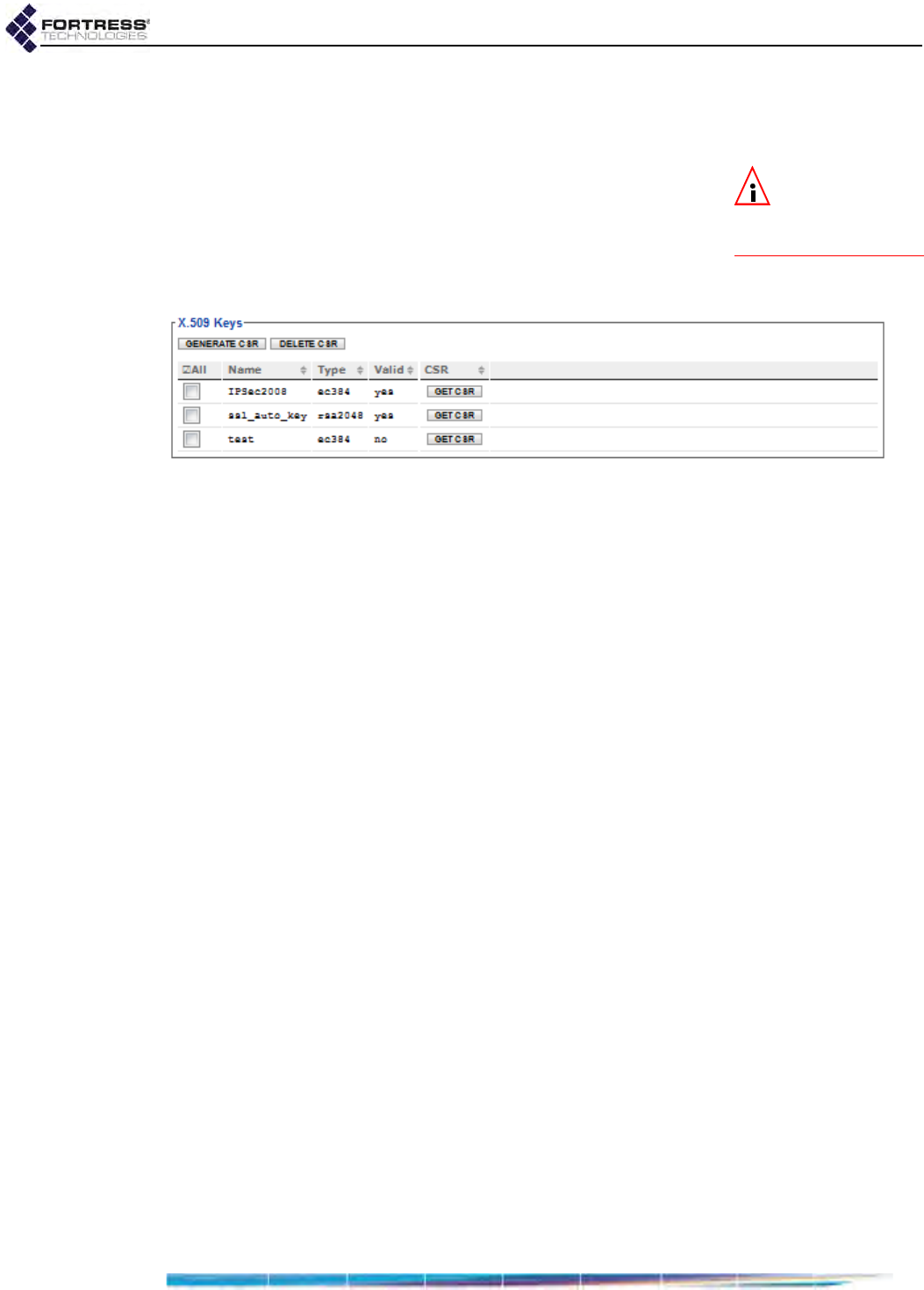
Bridge GUI Guide: Maintenance
202
3In the resulting Generate KeyPair frame, enter values into
the fields provided (described above) and click APPLY (or
CANCEL the addition).
NOTE: You can re-
trieve the CSR for
a key pair with the asso-
ciated GET CSR button.
The generation of the CSR will be recorded in the X.509 Keys
frame, with the associated key pair displayed by Name, with
fields indicating the key Type and whether a certificate
corresponding to the key pair is present in the local store (Valid
displays yes) or no certificate has yet been imported for the key
pair (Valid displays no).
Figure 6.10.
X.509 Keys
frame, all platforms
To delete public/private key pairs:
You can delete a single key pair, selected key pairs, or all key
pairs present on the Bridge.
1Log on to the Bridge GUI through an Administrator-level
account and select Maintain -> Certificates from the menu
on the left.
2In the X.509 Keys frame of the Certificates screen:
If you want to delete a single or selected key pair(s),
click to place a checkmark in the box(es) beside the
key(s) you want to eliminate.
or
If you want to delete all key pairs, click ALL at the top of
the X.509 Keys list to checkmark all keys.
Click the DELETE CSR button (or CANCEL the deletion).
3Click OK in the confirmation dialog (or CANCEL).
Deleted key pairs are removed from the X.509 Keys list.
6.2.2 Managing Local Certificates
The Bridge’s self-signed certificate, used by default for the
Bridge GUI, is automatically generated and always present in
the local certificate store.
You can import additional PEM-formatted or ASN.1 DER
encoded X.509 signed certificate files into the Bridge’s
certificate store, and you can assign digital certificates stored
on the Bridge to be used by specific Bridge functions.
6.2.2.1 Importing and Deleting Signed Certificates
An imported certificate can be:
the certificate of a trusted root CA
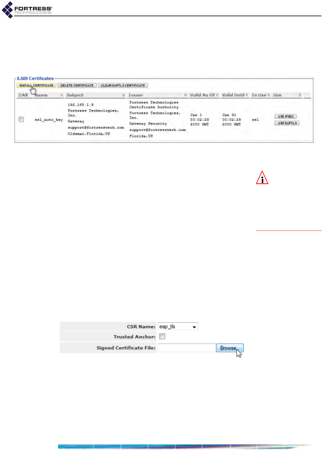
Bridge GUI Guide: Maintenance
203
an intermediate CA certificate
an end certificate corresponding to a public key manually
generated on the Bridge with the GENERATE KEY/CSR button
(described above) or Bridge CLI generate command (refer
to the CLI Software Guide).
Figure 6.11.
X.509 Certificates
frame, all platforms
In order to import a signed digital certificate, you must specify:
NOTE: The certifi-
cate contains the
information necessary
to determine whether
the certificate belongs to
a CA or to an end entity
or whether it is a root
certificate.
CSR Name or Certificate Name - specifies a name for the
imported certificate, used to identify the certificate on the
Bridge.
If the certificate is an end certificate, you must select the
CSR Name associated with the certificate’s public key from
the dropdown.
If the certificate is a trust anchor certificate, you must first
check the box to indicate this (see below), and then enter a
Certificate Name unique to the local certificate store. The
name does not have to be related to either the issuer or
subject DN in the certificate.
Trusted Anchor - when more than one root CA certificate is
present, selects which will serve as trust anchors, or root
certificates signed by trusted CAs in chains of trust
applicable to the Bridge’s current requirements.
Signed Certificate File - permits you to Browse to the location
of the certificate file to be imported.
Figure 6.12.
Upload Certificate
frame, all platforms
In addition to the certificate’s Name, the X.509 Certificates list
displays:
Subject - shows the IP address of the device that generated
the associated CSR and the subject X.500 distinguished
name (DN), consisting a concatenation of selected
attributes, or relative distinguished name (RDNs).

Bridge GUI Guide: Maintenance
204
Issuer - identifies the issuer X.500 DN.
Valid As Of /Valid Until - define the time span during which
the certificate is valid by start and end times.
In Use - identifies the Bridge function to which the certificate
is assigned.
Use - provides controls for assigning the certificate for use
by specific Bridge functions.
Section 6.2.2.2 (below) covers the possible values of In Use
and instructions for the buttons under Use.
To import a signed certificate file:
1Log on to the Bridge GUI through an Administrator-level
account and select Maintain -> Certificates from the menu
on the left.
2In the X.509 Certificates frame of the Certificates screen,
click INSTALL CERTIFICATE.
3In the resulting Install a signed certificate dialog, enter
values into the fields provided (described above) and click
APPLY (or CANCEL the action).
The imported certificate will be listed in the X.509 Certificates
frame.
To delete digital certificates:
NOTE: If you de-
lete the self-signed
certificate, the Bridge
will automatically gen-
erate a new one.
You can delete a single or selected certificate(s), or all
certificates in the Bridge’s certificate store.
1Log on to the Bridge GUI through an Administrator-level
account and select Maintain -> Certificates from the menu
on the left.
2In the X.509 Certificates frame of the Certificates screen:
If you want to delete a single or selected certificate(s),
click to place a checkmark in the box(es) beside the
certificate(s) you want to eliminate.
or
If you want to delete all certificates, click ALL at the top
of the X.509 Certificates list to checkmark all accounts.
Click the DELETE checked certificates button (or CANCEL the
deletion).
3Click OK in the confirmation dialog (or CANCEL).
Deleted certificates are removed from the X.509 Certificates list.
With the exception of the self-signed SSL certificate, if a
deleted certificate was in use, the function to which it was
assigned will no longer be able to perform certificate-
dependent authentication transactions until a new valid
certificate is assigned.

Bridge GUI Guide: Maintenance
205
6.2.2.2 Assigning Stored Certificates to Bridge Functions
Locally stored signed certificates can have any of three
applications on the Bridge, as indicated in the In Use column of
the X.509 Certificates list:
ssl - the Secure Socket Layer certificate is used by the
Bridge GUI to secure browser connections to the
management interface via https (refer to Section 2.1.2).
By default, the Bridge GUI uses the automatically
generated self-signed certificate for SSL. When additional
certificates have been imported, you can change this
assignment.
IPsec - the Internet Protocol Security certificate is used to
authenticate the Bridge as an endpoint in IPsec
transactions (refer to Section 4.2).
eaptls - the Extensible Authentication Protocol-Transport
Layer Security certificate is used:
to authenticate EAP-TLS 802.1X supplicants—when
the Bridge’s internal authentication server is configured
to provide 802.1X authentication service (refer to
Section 4.3.2).
to authenticate an ES210 Bridge as a wireless station—
when it is dedicated to act as a wireless Client (refer to
Section 3.3.5.10).
Because Bridges used as wireless Clients must be
dedicated to the function, the EAP-TLS certificate will only
be used for one of these applications.
A given function can have only one certificate assigned to it.
You can, however, assign the same certificate to more than
one function.
To assign local certificates to Bridge functions:
1Log on to the Bridge GUI through an Administrator-level
account and select Maintain -> Certificates from the menu
on the left.
2In the X.509 Certificates frame of the Certificates screen, in
the Use column, click the button for the relevant function:
USE IPSEC or USE EAPTLS, to the right of the certificate you
are assigning to that function.
The button(s) for a given function will only be present if no
certificate has yet been assigned to it.
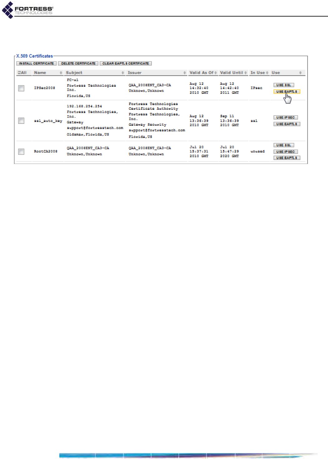
Bridge GUI Guide: Maintenance
206
The specified function will be listed for that certificate in the
X.509 Certificates frame, under In Use.
Figure 6.13.
X.509 Certificates
frame, all platforms
6.2.2.3 Changing and Clearing Certificate Assignments
You can change the SSL certificate assignment from the
default, automatically generated, self-signed certificate, but you
cannot configure the Bridge to use no digital certificate for SSL.
If you assign a different certificate to the function, and then
delete that certificate or the associated key pair (or if the
certificate and key pair are mismatched), the Bridge GUI SSL
function will revert to using the default certificate.
Once established, you can also change the certificates
assigned to EAP-TLS and to IPsec.
To change certificate assignments:
1Log on to the Bridge GUI through an Administrator-level
account and select Maintain -> Certificates from the menu
on the left.
2In the X.509 Certificates frame of the Certificates screen, to
the right of the certificate you want to assign, click the
relevant button for the function you want to assign it to: USE
SSL, USE IPSEC, or USE EAPTLS.
The selected function will be displayed for the newly assigned
certificate in the In Use column of the X.509 Certificates list, and
the button for the function will be added to the Use column of
the certificate formerly assigned to it.
You can use the CLEAR EAPTLS CERTIFICATE button to return the
Bridge’s EAP-TLS function to the default state, in which no
certificate is assigned and only PSK is used for authentication
(if pre-shared keys have been configured). Refer to Section
4.3.2.7 for more information on the local 802.1X authentication
service and to Section 3.3.5.10 for more on authenticating
ES210 Bridges deployed as wireless clients.

Bridge GUI Guide: Maintenance
207
The CLEAR IPSEC CERTIFICATE button likewise returns the
Bridge’s IPsec function to the default state, in which no
certificate is assigned and only PSK is used to authenticate
IPsec peers (if pre-shared keys have been configured). Refer
to Section 4.2 for more information on IPsec operation and
configuration.
To clear certificate assignments:
1Log on to the Bridge GUI through an Administrator-level
account and select Maintain -> Certificates from the menu
on the left.
2In the X.509 Certificates frame of the Certificates screen,
click the button at the top of the frame that corresponds to
the function for which you want to clear the certificate:
CLEAR EAPTLS CERTIFICATE
or
CLEAR IPSEC CERTIFICATE
There must be a valid certificate assigned to the application in
order for authentication transactions to be successfully
performed by the Bridge for the corresponding function.
6.3 Features Licensing
There are various optional features on Fortress Bridges that
you can enable only after entering or uploading valid license
keys for these functions.
mesh - FastPath Mesh enables Fortress’s FastPath Mesh
bridging link management function (refer to Section 3.2.1).
This feature applies to all Fortress Bridges.
advradio - Advanced Radio enables 802.11a radio support
for additional licensed and unlicensed frequencies (refer to
Section 3.3.1). This feature applies only to radio-equipped
Bridges; refer to Section 1.3.1.
country - Country enables an additional 70 selectable
countries of operation through which to identify the
regulatory domain for Bridge 802.11a radio operation (refer
to Section 3.3.1.3). This feature applies only to radio-
equipped Bridges; refer to Section 1.3.1.
suite-b - Suite B Security enables support for an additional
key establishment method that employs NSA (National
Security Agency) Suite B cryptography (refer to Section
4.1.3). This feature applies to all Fortress Bridges.
perf-level - Performance Level allows for three field-
upgradable performance configurations for the FC-X.
Performance level numbers represent optimum
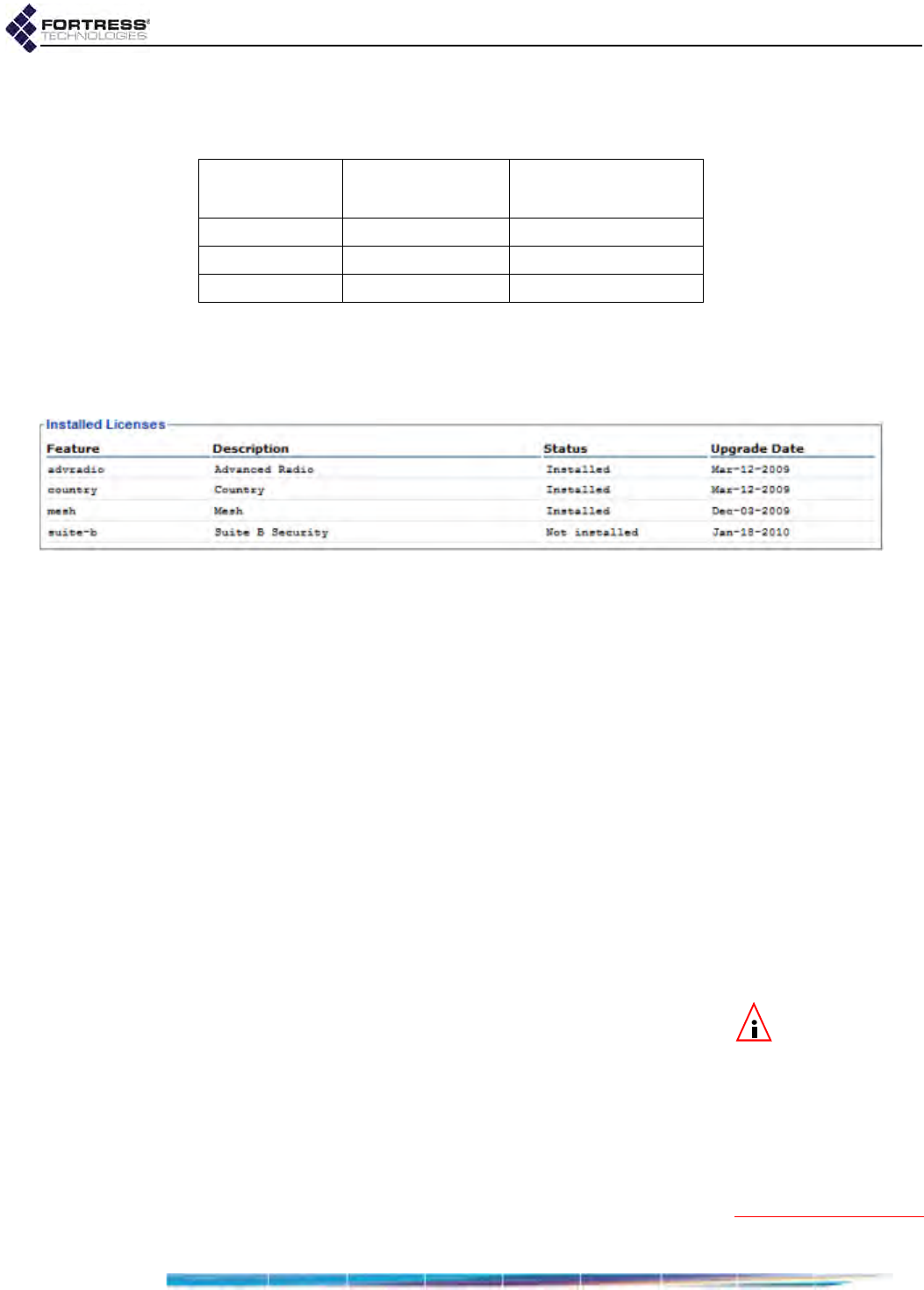
Bridge GUI Guide: Maintenance
208
performance at that level, with no more than the maximum
number of active connections shown in Table 6.2.
This feature applies only to FC-X model Fortress
Controllers.
Figure 6.14. Advanced View
Installed Licenses
frame, all platforms
The Bridge GUI displays licensing options and the status of
each on Maintain -> Licensing, available only in Advanced View.
The Advanced Radio and Country licensed features are
automatically enabled when you enter or upload valid license
keys for the feature, as are performance upgrades for the
FC-X.
Once licensed, FastPath Mesh can be enabled on Configure ->
Administration in Bridging Configuration (in Simple View and
Advanced View) and on Configure -> FastPath Mesh (in
Advanced View only).
After it has been licensed, Suite B can be enabled on Configure
-> Security.
By default, no licenses are installed nor licensed features
enabled on the Bridge.
6.3.1 Obtaining License Keys
NOTE: If you pur-
chased the Bridge
with a license for a giv-
en feature, the license
key is included in your
shipment. You can ob-
tain special feature li-
censes after your initial
purchase from Fortress
Technologies.
A unique, 20-character, hexadecimal key is required for each
licensed feature on each Bridge, based on the Bridge’s serial
number.
Fortress can generate a single 20-digit license key for a single
feature on a single Fortress Bridge, or a set of license keys for
multiple features and/or multiple Bridges in a group license text
file.
Fortress’s group license files contain all the information needed
to license a given set of features on a given set of Bridges. You
Table 6.2. Performance Levels
Configuration Encrypted
Throughput Maximum
Active Devicesa
a. concurrently connected Secure Clients, Trusted Devices
and APs
FC-250: 250 Mbps 500
FC-500: 500 Mbps 1000
FC-1500: 1.5 Gbps 3000
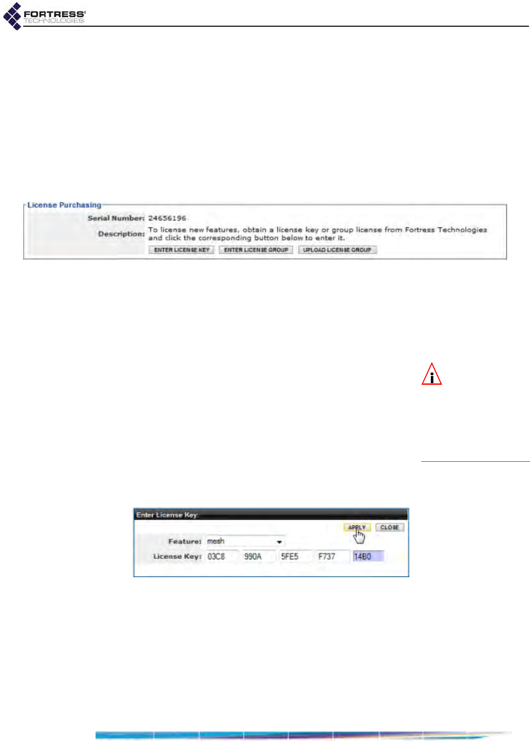
Bridge GUI Guide: Maintenance
209
must upload the file—or paste the entire file into the field
provided—on each Bridge it applies to. (Refer to Section 6.3.2
for detailed instructions.)
If you have not yet obtained a license key or group license for
feature(s) you want to enable on Bridge(s) already in your
possession, you will need to give Fortress Technologies the
serial number of each Bridge on which you wish to enable a
new feature.
The serial number is displayed on the first frame of Maintain ->
Licensing.
Figure 6.15. Advanced View
License Purchasing
frame, all platforms
Call your Fortress Technologies sales representative to
purchase a new feature or group license and obtain valid
license keys.
You can access Bridge GUI licensing screens and functions
only in Advanced View.
NOTE: Bridge fea-
ture licensing is
unchanged when con-
figuration settings are
restored from a backup
file or reset to their fac-
tory defaults (refer to
Section 6.1.8).
6.3.2 Licensing New Features
1Log on to the Bridge GUI through an Administrator-level
account and select ADVANCED VIEW in the upper right corner
of the page, then Maintain -> Licensing from the menu on
the left.
2In the License Purchasing frame of the Licensing screen,
click the button that corresponds to the action you want to
perform:
ENTER LICENSE KEY - to enter a single key for a single
advanced feature.
Figure 6.16. Advanced View
Enter License Key
dialog, all platforms
ENTER LICENSE GROUP - to enter a plaintext group
license file that covers multiple Bridges and/or multiple
features: Copy and paste the entire license file into the
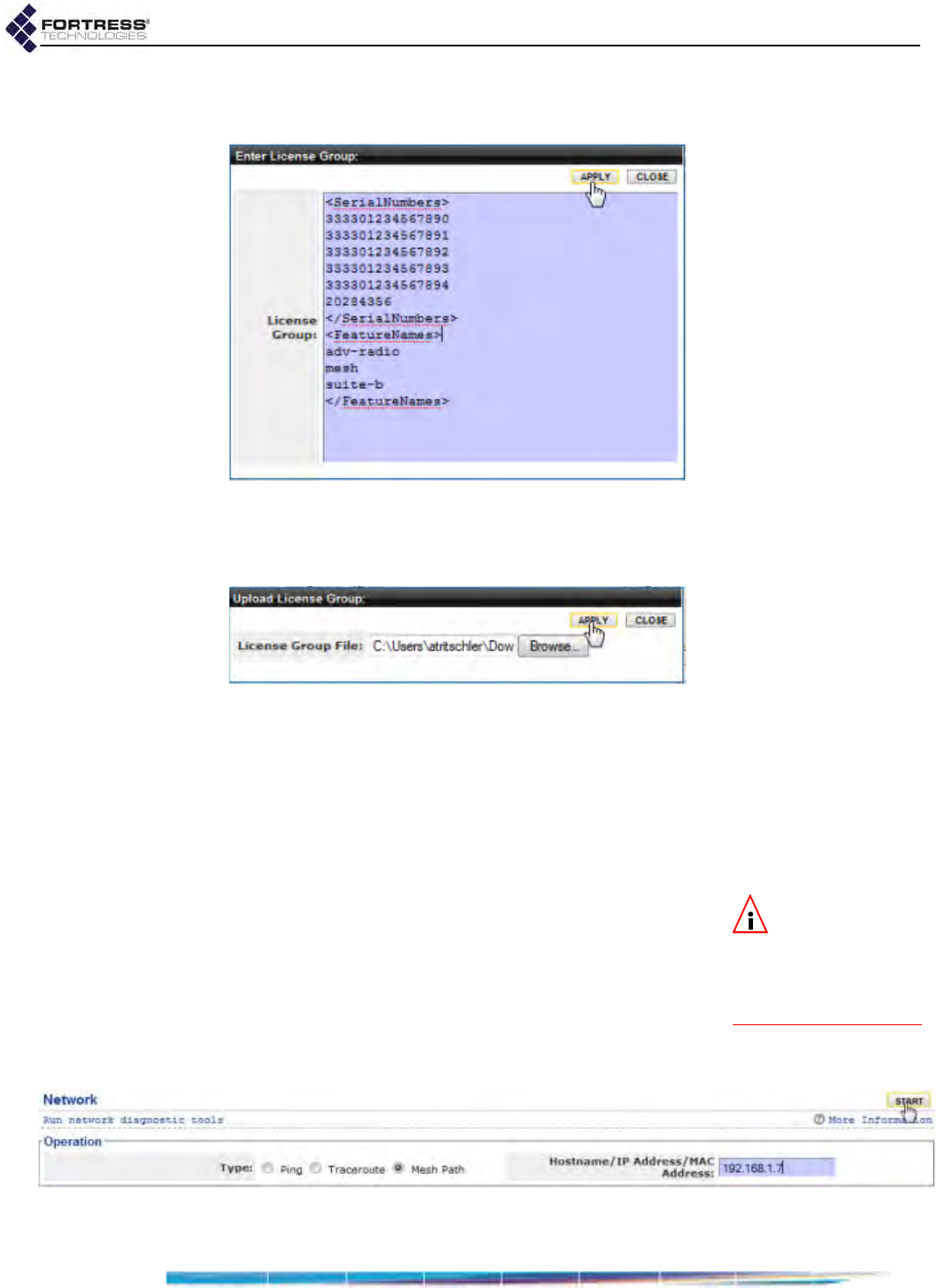
Bridge GUI Guide: Maintenance
210
field provided. (Group licensing files include a digital
signature and must be used intact.)
Figure 6.17. Advanced View
Enter License Group
dialog, all platforms
UPLOAD LICENSE GROUP - to browse to the location of a
group licensing file and select it for upload.
Figure 6.18. Advanced View
Upload License Group
dialog, all platforms
3In the resulting dialog, enter the license key or group
license file, or browse to and select the group license file,
and click Apply.
4As the Bridge GUI indicates, you must reboot the Bridge in
order for the license to take effect. Do so according to the
directions in Section 6.1.2.
NOTE: The Mesh
Path trace tool is
intended for use only
when FastPath Mesh is
licensed and enabled on
the Bridge.
6.4 Network Tools
Maintain -> Network provides standard ICMP (Internet Control
Message Protocol) ping and traceroute tools.
If FastPath Mesh is enabled (refer to Section 3.2.1), the screen
also provides a Mesh Path trace tool that displays the total end-
to-end cost to reach a particular node in a FastPath Mesh
network, along with each hop with its associated cost.
Figure 6.19.
Network
diagnostics screen, all platforms
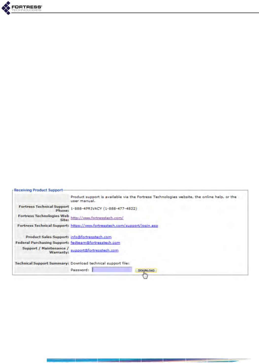
Bridge GUI Guide: Maintenance
211
1Log on to the Bridge GUI through an Administrator-level or a
Maintenance-level account and select Maintain -> Network
from the menu on the left.
2In the Network screen’s Operation frame, use the Type radio
buttons to select the tool you want to use: Ping, Traceroute
or Mesh Path.
3In the same frame, in Hostname/IP Address, enter the IP
address (IPv4 or IPv6) or hostname of the device you want
to ping or trace a route to.
4Click START in the upper right of the screen.
The Bridge will ping the target IP or trace a packet to the
address, according to your selection in Step 2, and display
the Result.
5To interrupt the operation, click STOP in the upper right of
the screen.
6.5 Support Package Diagnostics Files
To assist in diagnosing a problem with the Bridge, Technical
Support may request that you generate a diagnostics file.
Diagnostics files encrypt the information collected from the
Bridge, so the file can be securely sent as an e-mail
attachment.
Figure 6.20.
Receiving Product Support
frame, all platforms
1Log on to the Bridge GUI through an Administrator-level or a
Maintenance-level account and select Maintain -> Support
from the menu on the left.
2In the Support screen’s Receiving Product Support frame,
enter a Password for the support package file.

Bridge GUI Guide: Maintenance
212
NOTE: Support
package file pass-
words can be 1–20 al-
phanumeric characters
and/or symbols.
Record the password in a secure place; Fortress Technical
Support will need it to decrypt the support package file.
3Click DOWNLOAD, and, if your browser is set to block pop-
ups/file downloads, take the necessary actions to allow the
file to download.
The progress of file generation is displayed.
4When the download completes, Save the file, support.pkg,
to the location of your choice.

Bridge GUI Guide: Index
I
Index
Numerics
3rd-party AP management 155–159
4.4 GHz radio
see military band radio
802.11a/b/g see radios
802.11i authentication
BSS Wi-Fi security 77–80
STA interface Wi-Fi security 84–86
802.11n 62–63, 76
802.1X authentication 141–142
cleartext setting 122
digital certificates 205
Ethernet ports 104
local server 141–142
servers 78, 84, 134–135, 141–142
A
Access Control Lists 150–159
administrative IP address ACL 39–41
cleartext device access 155–159
controller device access 153–155
IPsec ACL 132–133
MAC address ACL 151–153
Access ID 125–126
administrative accounts 19–41
authentication 22–25
individual accounts 30–38
administrative state 31
audit logging 32
in local user database 144
interface permissions 32
password controls 33–34
preconfigured accounts 19, 30
role 31–32, 144
user names 31
logon controls 20–25
configuration steps 27
logon message 28
configuration steps 29
passwords 20, 25–27, 33–34
changing 38–39
complexity 26–27
configuring requirements 27
defaults 16, 20, 33, 34
expiration 25
individual account controls 33–34
unlocking 39
AES-128/192/256
see encryption algorithm
altitude
see location settings
antennas
see radios
AP management rules 155–159
AP/TD
see cleartext devices
archive settings
see backup and restore
associations
configuring BSSs 70–81
monitoring 170–171
STA interface 87–89
audit logging 159–165
individual administrative accounts 32
see also system log
authentication
802.1X authentication
Ethernet ports 104
local server 141–142
servers 134–135, 141–142
administrator authentication 22–25
authentication servers 133–142
Client device authentication 146–149
default settings 146–147
controller device authentication 153–155
default settings 153
user authentication 143–145
default settings 140, 143
WPA/WPA2 authentication
BSSs 78–80
STA interface 84–86
AUX port
see Ethernet ports
B
backup and restore 196–198
backing up 197
restoring 198
Basic Service Sets 70–80
monitoring associations 170–171
security settings 77–80
see also radios
beacon interval 123
configuration steps 124
blackout mode 120
configuration steps 124

Bridge GUI Guide: Index
II
boot image 194, 196
BPM
see FIPS, bypass mode
Bridge GUI
see GUI
bridging 5–14, 47–57
FastPath Mesh 5–12, 47–55
monitoring 183–189
network topologies 6–12
interfaces 72
FastPath Mesh 48, 73
received signal strength setting 72
monitoring bridging links 171–173
point-to-point 14
Spanning Tree Protocol 12–13, 56–57
browser support 16
BSS
see Basic Service Sets
C
cached user credentials 123
configuration steps 124
channel exclusion 69–70
channel settings 59, 60
configuration steps 67
cleartext devices 155–159
managing the Bridge 122–123
viewing 177
cleartext LED 118, 166
cleartext setting 121–122
configuration steps 124
CLI SSH access 120
Clients
see Secure Clients
compatibility
hardware 3
software 15
compression 121
configuration steps 124
console port 115–116
controller devices 175
ACL authentication 153–155
monitoring connections 175
controller properties
see network settings
country of operation 58–59
crypto algorithm
see encryption algorithm
Crypto Officer 118
D
data compression 121
configuration steps 124
date and time
system date and time 95
configuration steps 97
default
Access ID 125
administrative passwords 16, 20, 33, 34
Client device authentication settings 146–147
controller device authentication settings 153
encryption algorithm 118
idle timeout settings 139, 144
IP address 16, 93
operating mode 117
re-keying interval 120
restoring defaults 199–200
SNMP passphrase 42
upgrade file password 195
user authentication settings 140, 143
device authentication 146–149
Client device authentication
default settings 146–147
individual device settings 147–148
controller device authentication 153–155
default settings 153
see also Device ID
Device ID 146, 153, 168
controller devices Device ID 175
local Bridge Device ID 168
Secure Client Device ID 147, 173
DFS operation 68–69
DHCP services 98–100
diagnostics file 211–212
digital certificates 200–207
assigning 205–207
generating 201–202
importing 202–204
digital signatures
see digital certificates
distance
setting 65–66
units 58
DNS client settings 91, 92
configuration steps 92
DNS service 100–102
domain name 91, 92, 98, 100
FastPath Mesh 47, 49
domain name 91, 92, 98, 100
FastPath Mesh 47, 49

Bridge GUI Guide: Index
III
DTIM period 74
dynamic frequency selection
see DFS operation
E
EAP-TLS 141–142
BSS WPA 78–79
digital certificate 205–207
local authentication server 141–142
STA interface WPA 84–85, 89
encrypted interfaces 77–80, 102, 104
BSSs 77–80
cleartext traffic 121–122
Ethernet 102, 104
FastPath Mesh 47
management access 122
encryption algorithm 118
configuration steps 124
default 118
in Secure Clients 118
environment setting 59
Ethernet ports 102–106
F
FastPath Mesh 5–12, 47–55
interfaces 5, 48
Ethernet 103
wireless 72–73
licensing 209–210
monitoring 183–189
network topologies 6–12
tracing a mesh path 210
tuning performance 51–52
FIPS 117–121, 166–167, 198–199
bypass mode 118, 166
configuration steps 124
indicators 166–167
cleartext LED 118, 166
operating mode 117–121
retesting 198–199
Fortress Secure Client
see Secure Clients
Fortress Security
BSSs 77
Ethernet ports 104
FastPath Mesh 47
see also security settings
fragmentation threshold 75, 83
G
GPS 97–98
guest devices
see cleartext devices;
Trusted Devices, guest device access
guest management
see cleartext devices, guest devices
managing the Bridge
GUI 16–19
accessing 16–19
administrative accounts 19
configuration steps 30–38
enabling/disabling 120
getting help 19
security 16
GUI certification
see digital certificates
H
hardware 3
Ethernet ports 102
radios 57
serial port 115
help 19
host devices
configuring timeouts 123–124
resetting 192–193
host name 91
configuration steps 92
I
interference 67
IPsec 126–133
ACL 132–133
monitoring 182–183
pre-shared keys 131–132
SPD 128–130
IPv4 93
configuration steps 95
default address 16, 93
IPv6 93–95
configuration steps 95
K
key establishment 119
licensing Suite B 207
Secure Client configuration 119
key pair
see digital certificates

Bridge GUI Guide: Index
IV
L
LAN settings
see network settings
latitude and longitude
see location settings
LEDs
blackout mode 120
configuration steps 124
licensed features 207–210
adding 209–210
location settings 97–98
logging on/off
global logon settings 20–25
logging on/off 16–19
logon message 28
configuration steps 29
see also administrative accounts
M
MAC addresses
ACL filtering 151–153
cleartext device MAC addresses 156, 157
viewing 177
controller device MAC addresses 154
viewing 175
Secure Client MAC addresses 147
viewing 173
management interface
IP address 93
configuration steps 95
default 16, 93
mesh
see FastPath Mesh;
STP
mesh path
see FastPath Mesh, tracing a mesh path
MIB 41
military band radio 3–4, 46, 57
channels 63
DFS 69
EULA addendum vi
regulation 59
monitor resolution 16
MSP 2, 5, 117
Access ID 125–126
beacon interval 123
configuration steps 124
encryption 118
key establishment 119
MSP Clients 173
re-keying interval 120
see also security settings
N
network settings 91–95
configuration steps 92, 95
DHCP services 98–100
DNS client settings 92
DNS service 100–102
host name 91
IPv4 settings 93
IPv6 settings 93–95
network topologies 5–14
topology view 168–170
NTP 96
O
operating mode 117–121
configuration steps 124
default 117
FIPS 117–121
Normal 117
P
passwords
administrator passwords 20, 25–27, 33–34
account controls 33–34
changing 38–39
defaults 16, 20, 33, 34
expiration 25
complexity 26–27
configuring requirements 27
SNMP passphrases 42
upgrade file password 195
user passwords 144
ping 210–211
PoE 3, 102
per port PSE 105–106
point-to-point bridging 14, 64

Bridge GUI Guide: Index
V
ports
authentication server ports 136, 139
Ethernet 102–106
for AP management rules 157
for Trusted Devices 158
serial port 115–116
public key certificate
see digital certificates
Q
QoS 107–108
BSS WMM 74
Ethernet port override 105
STA interface WMM 82
quality of service
see QoS
R
radios 3, 46, 57–90
channel exclusion 69–70
DFS operation 68–69
military band radio 3–4, 46, 57
channels 63
DFS 69
EULA addendum vi
regulation 59
monitoring bridging links 171–173
monitoring BSS associations 170–171
radio settings 57–70
administrative state 61
antenna gain 64
band 61
beacon interval 66
BSS settings 70–80
channel 59, 60
configuration steps 67
country 58–59
distance 65–66
distance units 58
environment 59
network type 64
noise immunity 67
preamble 67
STA interface 81–90
transmit power 60, 65
received signal strength 72, 170, 171
RF kill 58
wireless interfaces 70–90
rebooting 193
re-keying interval 120
configuration steps 124
default 120
remote logging 159–165
individual administrative accounts 32
resetting
factory defaults 199–200
resetting connections 192
restoring
default settings 199–200
from a backup file 198
previous software version 196
RF kill 58
RTS threshold 75, 83
S
safety
precautions 1
Secure Clients 5
compatibility 15
device authentication 146–149
encryption configuration 118
key establishment 119
managing the Bridge 122
monitoring 173–175
resetting 192–193
timeout settings 123–124, 139–140, 144–145
Secure Shell
see SSH
security settings 77–80, 104, 117–126
Access ID 125–126
administrator passwords 20, 25–27, 33–34
account controls 33–34
changing 38–39
expiration 25
allow cached credentials 123
beacon interval 123
blackout mode 120
BSS security 77–80
cleartext traffic 121–122
compression 121
configuration steps 124
encryption algorithm 118
GUI access 120
key establishment 119
operating mode 117–121
passwords
complexity 26–27
configuring requirements 27
re-keying interval 120
RF kill 58
SSH 120
serial port 115–116

Bridge GUI Guide: Index
VI
sessions
monitoring 173–177
resetting 192
timeout settings 123–124, 139–140, 144–145
SNMP 4, 41–45
MIB 41
SNMP traps 43–45
software upgrades 194–196
reverting 196
upgrade file password 195
software version
boot image 194
restoring previous version 196
upgrading 194–196
viewing 193
Spanning Tree Protocol
see STP
SSH 120
SSIDs 71
see also Basic Service Sets
STA interface 81–90
scanning for networks 87–89
WPA/WPA2 authentication 84–86
station mode
see STA interface
statistics 178–180
interface statistics 179–180
traffic statistics 178–179
VLAN statistics 182
STP 12–13, 56–57
Suite B 2, 126
cipher suite
802.1X authentication 141
IPsec 128
STA interface 85
key establishment 119
licensing 207
support file 211–212
system clock 95
configuration steps 97
system log 189–191
see also audit logging
system requirements 16
T
third-party AP management 155–159
time zone 95
configuration steps 97
timeout settings
administrative timeouts 21
default 21
session and idle timeouts 123–124, 139–140,
144–145
default 139, 144–145
topology 5–14
topology view 168–170
traceroute 210–211
transmit power settings 60, 65
configuration steps 67
Trusted Devices 155–159
guest device access 157
managing the Bridge 122–123
resetting 192–193
timeout settings 123–124
U
upgrades
see licensed features;
software upgrades
user accounts 144–146
see also administrative accounts
user authentication 140, 143–145
cached credentials 123
default settings 140, 143
V
version
see software version
VLANs 109–114
configuration steps 111–114
viewing statistics 182
W
WAN port
see Ethernet ports
wireless client mode 81–90
wireless interfaces 70–90
see also radios
WMM 107, 107–108
BSSs 74
STA interface 82
WPA/WPA2 authentication
BSSs 78–80
STA interface 84–86
Z
zone 171
see also Fortress Security

ES520 Bridge: Glossary
VIII
Glossary
3DES
Triple Data Encryption Standard—a FIPS-approved NIST standard for data encryption
using 192-bits (168-bit encryption, 24 parity bits) for protecting sensitive (unclassified)
U.S. government (and related) data. NIST amended and re-approved 3DES for FIPS in
May, 2004.
802.11 The IEEE standard that specifies technologies for wireless networks.
802.11i The amendment to the 802.11 standard that describes security for wireless networks,
or
Robust Security Networks
.
802.1X The IEEE standard for port-based network access control, providing authentication and
authorization to devices attached to a given port (or preventing access from that port if
authentication fails).
802.16 The IEEE standard that specifies technologies for fixed broadband wireless MANs that
use a point-to-multipoint architecture, also called WiMAX, WirelessMAN™ or the Air
Interface Standard.
Access ID
In Fortress Technologies products, a user-defined, 16-digit hexadecimal value that pro-
vides network authentication for all devices authorized to communicate over a Fortress-
secured network. Network authentication is one of the components of Multi-factor
Authentication™.
access point (AP) A device that transmits and receives data between a wired LAN and a WLAN, to connect
wireless devices within range to the LAN.
AES
Advanced Encryption Standard—a FIPS-approved NIST standard for 128/192/256-bit
data encryption for protecting sensitive (unclassified) U.S. government (and related)
data; also referred to as the
Rijndael algorithm
. NIST FIPS-approved AES in November,
2001.
administrator password In Fortress Technologies products, a password that guards against unauthorized modifi-
cations to the system or its components (compare user password).
APIPA Automatic Private IP Addressing—a Microsoft feature that allows a DHCP client unable
to acquire an address from a DHCP server to automatically configure itself with an IP
address from a reserved range (169.254.0.1 through 169.254.255.254). The client uses
the self-configured IP address until a DHCP server becomes available.
ARP Address Resolution Protocol—describes how IP addresses are converted into physical,
DLC addresses (ex., MAC addresses).
AS
Authentication Server—a network device running an authentication service: software
that checks credentials to verify the identity of network users and/or devices in order to
restrict access to the network or to its resources or to track network activity.
Autonomous System—as defined by RFC 1930, a network or connected set of networks,
usually under a single administrative entity, with a single clearly defined routing policy;
“the unit of routing policy in the modern world of exterior routing.”

IX
ES520 Bridge: Glossary
ATM Asynchronous Transfer Mode—a technology for transferring data over a network in
packets or cells of a fixed size.
BGP Border Gateway Protocol—a protocol, defined by RFC 1771, for interautonomous sys-
tem routing; the interdomain routing protocol used by TCP/IP.
BPM In FIPS, bypass mode—state in which cleartext is allowed to pass on an encrypted
interface.
bridge A network device that connects two networks or two segments of the same network.
Bridge Refer to
Fortress Secure Bridge
and
Fortress Secure Wireless Bridge.
Bridge GUI The browser-based graphical user interface through which a Fortress Bridge is config-
ured and managed, locally or remotely.
BSS Basic Service Set—the primary collection of entities associated in a wireless network, as
defined in the IEEE 802.11 standard.
CAC Common Access Card—a United States Department of Defense (DoD) smartcard issued
as standard identification for active duty military personnel, reserve personnel, civilian
employees, and eligible contractor personnel.
CCITT Comite Consultatif Internationale de Telegraphie et Telephonie, former name of the
ITU-T.
CLI command-line interface—a user interface in which the user enters textual commands
on a single line on the monitor screen.
client In client-server architecture, an application that relies on another, shared application
(server) to perform some of its functions, typically for an end-user device.
Client Refer to
Fortress Secure Client
.
Controller Refer to
Fortress Controller
.
controller device See Fortress controller device
Controller GUI The browser-based graphical user interface through which the Fortress Controller is
configured and managed, locally or remotely.
Crypto Officer password A FIPS-defined term—sometimes,
Crypto password
—the a
dministrator password
in For-
tress devices operating in
FIPS
mode.
Data Link Layer Refer to
DLC
.
dBi decibels over isotropic—a unit of measure of RF antenna gain: the power emitted by an
antenna in its direction of strongest RF emission divided by the power that would be
transmitted by an isotropic antenna emitting the same total power.
dBm decibels referenced to milliwatts—an absolute (non-relative) unit of power measure-
ment that indicates the ratio, in decibels (dB), of measured power referenced to one
milliwatt (mW)
DES Data Encryption Standard—formerly, a FIPS-approved NIST standard for data encryp-
tion using 64 bits (56-bit encryption, 8 parity bits). NIST withdrew its FIPS-approval for
DES on May 19, 2005.
device authentication
In Fortress Technologies products, a means of controlling network access at the level of
individual devices, tracking them via their generated Device IDs and providing controls
to explicitly allow and disallow them on the network; one of the factors in Fortress’s
Multi-factor Authentication™.
Device ID
In Fortress Technologies products, a 16-digit hexadecimal value generated for and
unique to each Fortress Bridge, Controller or MSP Secure Client device on the Fortress-
secured network. Device IDs are used for
device authentication
and are neither modifi-
able nor transferable.

X
ES520 Bridge: Glossary
DHCP
Dynamic Host Configuration Protocol—an Internet protocol describing a method for
flexibly assigning device IP addresses from a defined pool of available addresses as
each networked device comes online, through a client-server architecture. DHCP is an
alternative to a network of fixed IP addresses.
Diffie-Hellman key establishment A protocol by which two parties with no prior knowledge of one another can agree upon
a shared secret key for symmetric key encryption of data over an insecure channel.
Also,
Diffie-Hellman-Merkle key establishment
;
exponential key exchange
.
DLC Data Link Control—the second lowest network layer in the OSI Model, also referred to
as the
Data Link Layer
,
OSI Layer 2
or simply
Layer 2
. The DLC layer contains two sub-
layers: the MAC and LLC layers.
DMZ Demilitarized Zone—in IT, a computer (or subnet) located between the private LAN and
a public network, usually the Internet.
DNS
Domain Name System
,
Server
or
Service
—a system or network service, defined in the
TCP/IP Internet Protocol Suite, that translates between textual domain and host names
and numerical IP addresses.
DoD Department of Defense—the United States military.
EAP Extensible Authentication Protocol—defined by RFC 2284, a general protocol for user
authentication. EAP is implemented by a number of authentication services, including
RADIUS.
EAP-MD5 An EAP security algorithm developed by RSA Security® that uses a 128-bit generated
number string to verify the authenticity of data transfers.
EAP-TLS EAP-Transport Layer Security—a Point-to-Point Protocol (PPP) extension supporting
mutual authentication, integrity-protected cipher suite negotiation, and key exchange
between two endpoints, within PPP.
EAP-TTLS EAP-Tunneled TLS—An EAP-TLS protocol developed by Funk and Certicom that uses
TLS to establish a secure connection between a client and server.
ES300 The Fortress hardware model identifier of the
Secure Bridge
.
ES520 The Fortress hardware model identifier of the
Secure Wireless Bridge
.
failover
A device or system configuration in which two, identical components are installed for a
given function so that if one of them fails the redundant component can carry on oper-
ations without substantial service interruption. Also, an instance in which an active
component becomes inoperative and
fails over
operations to its partner.
FC-XThe Fortress hardware model identifier of the
Fortress Controller
.
FIPS Federal Information Processing Standards—issued by NIST, FIPS mandate how IT,
including network security, is implemented by the U.S. government and associated
agencies.
FIPS operating mode In Fortress Technologies products, the operating mode that complies with FIPS 140-2
Security Level 2.
Fortress Controller Sometimes,
Fortress Security Controller
—Fortress’s FC-
X
model network device for
securing communications between wireless devices and a LAN, or between devices
within a LAN, or in a networked configuration.
Fortress controller device A collective noun for Fortress network devices (Fortress Bridges and Controllers).
Fortress Secure Client A software client module for securing network communications on devices such as lap-
tops, PDAs, tablet PCs, and industrial equipment such as barcode scanners and porta-
ble terminals.
Fortress Secure Client Bridge Also,
Fortress
SCB
or
SCB
—a hardware device for providing wireless connectivity and
securing network communications on wired devices such as portable medical equip-
ment and point-of-sale (POS) terminals.

XI
ES520 Bridge: Glossary
Fortress Security System The secure network deployment of one or more Fortress Bridges and the Fortress
Secure Clients and/or Secure Client Bridges that will communicate with the Bridge(s).
Fortress Secure Bridge Fortress’s ES300 model network device for securing communications between wireless
devices and a LAN, or between devices within a LAN, or in a networked configuration.
Fortress Secure Wireless Bridge Fortress’s ES520 model and ES210 model radio-equipped network devices that can act
as wireless access points and/or bridges in a mesh network.
FQDN Fully Qualified Domain Name—the complete, unambiguous domain name specifying the
exact location in the DNS hierarchy of a particular entity on the network.
frame
In Fortress Technologies GUIs, a portion of a larger screen or dialog, graphically set
apart from other elements on the screen and providing the interface for a specific fea-
ture or function set.
In IT, a packet of data transmitted/received.
gateway In IT, a node on a network, usually a router, that provides a connection to another net-
work.
GINA A library developed by Microsoft®; it is a component of some Microsoft Windows®
operating systems and provides secure authentication and interactive logon services.
GPS Global Positioning System
groups An association of network objects (users, devices, etc.) typically used to allocate shared
resources and apply access policies.
GUI graphical user interface—a user interface in which the user manipulates various interac-
tive objects (menu items, buttons, etc.) displayed on the monitor screen.
hash function Mathematical computation for deriving a condensed representation or
hash value
, usu-
ally a fixed-size string, from a variable-size message or data file.
HTTP Hypertext Transfer Protocol—used to transmit and receive all data over the World Wide
Web.
HTTPS HTTP Secure sockets—HTTP with an encryption/authentication layer.
IANA Internet Assigned Number Authority—the organization that assigns Internet Protocol
(IP) addresses and port numbers.
ICMP Internet Control Message Protocol —supports packets containing error, control, and
informational messages. The ping command uses ICMP to test an Internet connection.
IDS Intrusion Detection System—monitors network activity to identify suspicious patterns
that may indicate a network or system attack and supports automated and/or manual
real-time responses.
IEEE Institute of Electrical and Electronics Engineers—a nonprofit technical professional
association that develops, promotes, and reviews standards within the electronics and
computer science industries.
IETF Internet Engineering Task Force—the primary standards organization for the Internet.
IGMP Internet Group Management Protocol—The portion of the IP multicast specification that
describes dynamically managing the membership of multicast groups.
Internet Protocol Suite Also, TCP/IP—the basic, two-part communication protocol in use on the Internet (refer
to IP and TCP).
IP Internet Protocol—defines a method for transmitting data, in packets, from one com-
puter to another over a network; one of the founding protocols in the TCP/IP suite of
networking protocols.
IPS Intrusion Prevention System—allows network administrators to apply policies and rules
to network traffic, as it is monitored by an intrusion detection system.

XII
ES520 Bridge: Glossary
IPsec Internet Protocol security—a set of protocols developed by the IETF to support secure
exchange of packets at the IP layer, deployed widely to implement VPNs.
IPv4 Internet Protocol version 4—the first widely implemented and still the most prevalent
version of IP.
IPv6 Internet Protocol version 6—the next version of IP slated for wide implementation,
intended to overcome the limitations of, and to eventually replace, IPv4.
ISO International Organization for Standardization, formerly the International Standards
Organization—ISO still refers to standards (ex., ISO 9000); the whole name refers to
the organization, sometimes appending the earlier initialization in parentheses.
isotropic antenna A theoretical, idealized antenna that would transmit power uniformly in all directions;
used to measure antenna gain in dBi.
IT Information Technology
ITU-T International Telecommunications Union-Telecommunication, Geneva-based interna-
tional organization for telecommunications standards, formerly CCITT.
key establishment An transaction through which two parties with no prior knowledge of one another can
agree upon a shared secret key for symmetric key encryption of data over an insecure
channel. Sometimes, key exchange.
LAN Local Area Network—a collection of computers located within a small area (such as an
office building) that shares a common communications infrastructure and network
resources (i.e., printers, servers, etc.).
Layer 2 Refer to DLC.
LDAP
Lightweight Directory Access Protocol—a protocol used to access directories on a net-
work, including the Internet. LDAP makes it possible to search compliant directories to
locate information and resources on a network. LDAP is a streamlined version of the
Directory Access Protocol, part of the X.500 standard for network directory services.
LLC Logical Link Control—one of two sublayers of OSI Layer 2 (refer to
DLC
), in which frame
synchronization, flow control and error checking takes place.
MAC Media Access Control—one of two sublayers of the OSI Model’s DLC, at which data
access and transmission permissions are controlled.
MAC address Media Access Control address—a unique number that identifies a device, used to prop-
erly direct network traffic to the device.
MAN Metropolitan Area Network—a collection of interconnected computers within a town or
city.
MBG Mesh Border Gateway—in Fortress Secure Wireless Bridges, an MP that connects the
FastPath Mesh network to a conventional hierarchical network.
MIB Management Information Base—SNMP-compliant information that an SNMP agent
stores about itself and sends in response to SNMP server requests (PDUs).
MITM Man in the Middle attack—a network security breach in which an attacker is able to
intercept, read, insert and modify messages between two parties without their knowing
that the link between them has been compromised.
MLD Multicast Listener Discovery—a means, defined in the IPv6 ICMPv6 protocol, of discov-
ering multicast listeners on a directly attached link (analogous to IGMP in IPv4).
MobileLink™ In GE Medical Systems
Information Technologies
, a proprietary method for wireless
transmission of serial output.
MP Mesh Point—in Fortress Secure Wireless Bridges, a Bridge on which FastPath Mesh rout-
ing is enabled.
MRD Multicast Router Discovery—a mechanism, defined in IETF RFC 4286, for identifying
multicast routers independent of the multicast routing protocol they use.

XIII
ES520 Bridge: Glossary
MRP Mesh Radio Port—in Fortress Secure Wireless Bridges, a pair-wise network link formed
between WDS-enabled BSSs configured on the Bridges.
MSI The Microsoft installer system written by Microsoft for Windows platforms.
MSP The Fortress protocol that provides authentication and encryption at the Media Access
Control (MAC) sublayer, within the Data Link Layer (Layer 2) of the Open System Inter-
connection (OSI) networking model.
Multi-factor Authentication™ In Fortress Technologies products, the combination of network authentication (through
the network Access ID), device authentication (through the Device ID), and user
authentication (through user credentials), that guards the network against unwanted
access.
multiplexing The practice of transmitting multiple signals over a single connection.
NetBIOS Network Basic Input/Output System—an API that originally provided basic I/O services
for a PC-Network and that has been variously adapted and augmented to support cur-
rent LAN/WLAN technologies.
network authentication In Fortress Technologies products, the requirement that all devices must authenticate
with the correct
Access ID
in order to connect to the Fortress-secured network; one of
the factors in Fortress’s Multi-factor Authentication™.
network resource An entity on the network that provides a service or function, such as e-mail or printing,
to devices and users on the network.
NIC Network Interface Card—computer circuit board that enables a computer to connect to
a network.
NIAP
National Information Assurance Partnership—a collaboration between NIST and the
National Security Agency (NSA), in response to the Computer Security Act of 1987 (PL
100-235), to promote sound security requirements for IT products and systems and
appropriate measures for evaluating them.
NIST National Institute of Standards and Technology, the U.S. Government agency responsi-
ble for publishing FIPS.
NMP Non-Mesh Point—in Fortress Secure Wireless Bridges, any node on a Fortress FastPath
Mesh network that is not an MP.
NSA National Security Agency—United States intelligence agency administered by the
Department of Defense.
NTLM Windows NT LAN Manager—a user authentication protocol developed by Microsoft®.
operating mode In Fortress Technologies products, the way in which access controls and cryptographic
processing are implemented on the Fortress-secured network.
OSI Model
Open System Interconnection Model—an ISO standard that defines a networking
framework for implementing data transfer and processing protocols in seven layers.
(Also see,
DLC
.)
PAN Personal Area Network—a collection of networked computers and devices worn by or
within reach of an individual person
PDU Protocol Data Unit—often synonymous with
packet
, a unit of data and/or control infor-
mation as defined by an OSI layer protocol.
PKI Public Key Infrastructure (PKI), a system of digital certificates and other registration
authorities that authenticate the validity of each party involved in an Internet transac-
tion; sometimes, trusted hierarchy.
policy The means by which access to the secure network and its resources are controlled for
users, devices and groups.
PPP Point-to-Point Protocol—a method for communicating TCP/IP traffic over serial point-to-
point connections.

XIV
ES520 Bridge: Glossary
QoS Quality of Service
RSA SecurID® An authentication method created and owned by RSA Security.
RADIUS
Remote Authentication Dial-In User Service—an authentication service design that
issues challenges to connecting users for their usernames and passwords and authenti-
cates their responses against a database of valid usernames and passwords; described
in RFC 2865.
RF Radio Frequency
RFC Request for Comments—a document proposing an Internet standard that has been
accepted by the IETF as potentially developing into an established Internet standard.
RSN
Robust Security Network
- the concept, introduced in the 802.11i amendment to the
IEEE 802.11 standard, of a wireless security network that allows only
RSNAs
to be cre-
ated.
RSNA
Robust Security Network Association
- in the IEEE 802.11i amendment, a wireless con-
nection between 802.11i entities established through the 802.11i 4-Way Handshake key
management scheme.
RRL Resilient Radio Link—in Fortress Secure Wireless Bridges, active wireless links that form
along the best available path between the WDS-enabled BSSs of networked Bridges.
RRLs provide fault-tolerant connections for Fortress’s self-healing wireless networks.
SCB Refer to
Fortress Secure Client Bridge
.
Secure Client Refer to
Fortress Secure Client
.
Secure Client Bridge Refer to
Fortress Secure Client Bridge
.
Secure Client device In Fortress Technologies products, a device such as a laptop, PDA, tablet PC, or barcode
scanner, that has the Fortress Secure Client installed and configured to permit the
device to communicate on the Fortress-secured network.
SFP Small Form Pluggable—shorthand for fiber optic Small Form Pluggable transceiver.
SHA Secure Hash Algorithm, cryptographic hash functions developed by the NSA and pub-
lished by NIST in FIPS 180-2.
SHS Secure Hash Standard—FIPS-approved NIST standard specifying five secure hash algo-
rithms: SHA-1, SHA-224, SHA-256, SHA-384, and SHA-512
SLIP Serial Line Internet Protocol—a method for communicating over serial lines, developed
for dial-up connections.
SMTP Simple Mail Transfer Protocol—describes a method for transmitting e-mail between
servers.
SNMP
Simple Network Management Protocol—a set of protocols for simplifying management
of complex networks. The SNMP server sends requests (PDUs) to network devices, and
SNMP-compliant devices (SNMP agents) respond with data about themselves (stored in
MIBs).
SNMP agent Any network device running the SNMP daemon and storing a MIB, a client of the SNMP
server.
SSH® Secure Shell®, sometimes, Secure Socket Shell—a protocol, developed by SSH Com-
munication Security®, for providing authenticated and encrypted logon, file transfer
and remote command execution over a network.
SSID Service Set Identifier—a unique name that identifies a particular wireless network
STP Spanning Tree Protocol—a link management protocol, operating at OSI layer 2, that
prevents bridging loops while permitting path redundancy in a bridged network.
Suite B A set of cryptographic algorithms promulgated by the National Security Agency as part
of its Cryptographic Modernization Program. Suite B is available in the Secure Client
when licensed.

XV
ES520 Bridge: Glossary
SWLAN Secure Wireless Local Area Network
symmetric key encryption A class of cryptographic algorithm in which a shared secret between two or more par-
ties is used to maintain a private connection between or among them.
Tactical Mesh Point In Fortress Secure Wireless Bridges, alternative name for the ES210 Secure Wireless
Bridge.
TCP Transmission Control Protocol—defines a method for reliable (i.e., in order, with integ-
rity checking) delivery of data packets over a network; one of the founding protocols in
the TCP/IP suite of networking protocols.
TCP/IP Transmission Control Protocol/Internet Protocol, also Internet Protocol Suite—the basic,
two-part communication protocol in use on the Internet (refer to IP and TCP).
TLS
Transport Layer Security—a two-part protocol that defines secure data transmission
between client/server applications communicating over the Internet. TLS Record Proto-
col uses data encryption to secure data transfer, and the TLS Handshake Protocol allows
the client and server to authenticate each other and negotiate the encryption method
to use before exchanging data.
Trusted Device In Fortress Technologies products, a device that does not have the Secure Client
installed but is allowed network access through rules defined for it on the Fortress
Bridge.
trusted hierarchy Refer to PKI.
UDP User Datagram Protocol—defines a method for “best effort” delivery of data packets
over a network that, like TCP, runs on top of IP but, unlike TCP, does not guarantee the
order of delivery or provide integrity checking.
UI User Interface—the means by which a human end user provides input to and receives
output from computer software.
ULA Unique Local Address—an IPv6 globally unique unicast address (subnet identifier),
defined in IETF RFC 4193, intended for local (intranet) communications and not
intended to be routable on the Internet.
user authentication A mechanism for requiring users to submit established credentials (user name and
password, smartcard, etc.) and checking the validity of these credentials before allow-
ing users to log on to a device or network.
user password The password an end must enter in order to access a network or device that requires
user authentication (compare administrator password).
VLAN Virtual Local Area Network—a collection of computers configured through software to
behave as though they are members of the same network, even though they may be
physically connected to separate subnets.
VoIP Voice over IP, sometimes VOI (Voice over Internet)—any of several means for transmit-
ting audio communications over the Internet.
VPN Virtual Private Network—a private network of computers connected, entirely or in part,
by public phone lines.
WAN Wide Area Network—a collection of interconnected computers covering a large geo-
graphic area.
WDS Wireless Distribution System—a means for interconnecting multiple stations (STAs),
access points or nodes in a wireless network.
WEP Wired Equivalent Privacy—a security protocol for wireless networks, defined in the IEEE
802.11b amendment. WEP has been found to be vulnerable to attack, and WPA is
intended to supplant it in current and future 802.11 standards.
Wi-Fi® Wireless Fidelity—used generically to refer to any type of 802.11 network (referred
originally to the narrower 802.11b specification for WLANs).

XVI
ES520 Bridge: Glossary
WiMAX
Worldwide Interoperability for Microwave Access—the IEEE 802.16 specification for
fixed, broadband, wireless MANs that use a point-to-multipoint architecture, defining
bandwidth use in the licensed frequency range of 10GHz–66GHz and the licensed and
unlicensed frequency range of 2GHZ–11GHz.
WIDS Wireless Intrusion Detection System—a means for detecting and preventing unauthor-
ized or unwelcome connections to a network.
WLAN Wireless Local Area Network. A local area network that allows mobile users network
access through radio waves rather than cables.
WMM®Wi-Fi Multimedia wireless quality of service implementation defined in subset of the
IEEE standard 802.11e,
QoS for Wireless LAN
.
WPA
Wi-Fi Protected Access—a security protocol for wireless networks, defined in the IEEE
802.11i amendment, that uses 802.1X and EAP to restrict network access, and TKIP
encryption to secure data transfer. WPA is intended to replace WEP in current and
future 802.11 standards.
WPA2 Wi-Fi Protected Access 2—a later implementation of WPA that uses the FIPS 140-2
compliant AES encryption algorithm.