Fortress Technologies ES820 The ES820 is a dual radio access point/bridge. It provides secure connectivity through multiple Ethernet ports and two 802.11 a/b/g radios in a ruggedized enclosure. It provides secure, fixed or mobile communications for harsh environments. User Manual ES820 Secure Wireless Bridge rev 1
Fortress Technologies, Inc. The ES820 is a dual radio access point/bridge. It provides secure connectivity through multiple Ethernet ports and two 802.11 a/b/g radios in a ruggedized enclosure. It provides secure, fixed or mobile communications for harsh environments. ES820 Secure Wireless Bridge rev 1
Contents
HW Guide

ES820
Secure Wireless Bridge
Hardware Guide
www.fortresstech.com
© 2010 Fortress Technologies

ES820 Bridge
i
009-00025-00r1
Fortress ES820 Secure Wireless Bridge ES820 [rev.1]
Copyright © 2010 Fortress Technologies, Inc. All rights reserved.
This document contains proprietary information protected by copyright. No part of this
document may be reproduced or transmitted in any form or by any means, electronic or
mechanical, without written permission of Fortress Technologies, 4023 Tampa Road, Suite
2000, Oldsmar, FL 34677, except as specified in the Product Warranty and License Terms.
FORTRESS TECHNOLOGIES, INC., MAKES NO WARRANTY OF ANY KIND WITH
REGARD TO THIS MATERIAL, INCLUDING BUT NOT LIMITED TO THE IMPLIED
WARRANTIES OF MERCHANTABILITY AND FITNESS FOR A PARTICULAR PURPOSE.
FORTRESS TECHNOLOGIES, INC. SHALL NOT BE LIABLE FOR ERRORS
CONTAINED HEREIN OR FOR INCIDENTAL OR CONSEQUENTIAL DAMAGES IN
CONNECTION WITH THE FURNISHING, PERFORMANCE OR USE OF THIS
MATERIAL. THE INFORMATION IN THIS DOCUMENT IS SUBJECT TO CHANGE
WITHOUT NOTICE.
The Fortress Technologies and AirFortress logos and AirFortress and are registered
trademarks; Multi-Factor Authentication, Unified Security Model, Wireless Link Layer
Security and Three Factor Authentication (TFA) are trademarks of Fortress Technologies,
Inc. The technology behind Wireless Link Layer Security™ enjoys U.S. and international
patent protection under patent number 5,757,924.
All trademarks mentioned in this document are the property of their respective owners.
FCC EMISSIONS COMPLIANCE STATEMENT
THIS EQUIPMENT HAS BEEN TESTED AND FOUND TO COMPLY
WITH THE LIMITS FOR A CLASS B DIGITAL DEVICE, PURSUANT TO
PART 15 OF THE FCC RULES. THESE LIMITS ARE DESIGNED TO
PROVIDE REASONABLE PROTECTION AGAINST HARMFUL
INTERFERENCE IN A RESIDENTIAL INSTALLATION. THIS
EQUIPMENT GENERATES, USES, AND CAN RADIATE RADIO
FREQUENCY ENERGY AND, IF NOT INSTALLED AND USED IN
ACCORDANCE WITH THE INSTRUCTIONS, MAY CAUSE HARMFUL
INTERFERENCE TO RADIO COMMUNICATIONS. HOWEVER, THERE
IS NO GUARANTEE THAT INTERFERENCE WILL NOT OCCUR IN A
PARTICULAR INSTALLATION. IF THIS EQUIPMENT DOES CAUSE
HARMFUL INTERFERENCE TO RADIO OR TELEVISION RECEPTION,
WHICH CAN BE DETERMINED BY TURNING THE EQUIPMENT OFF
AND ON, THE USER IS ENCOURAGED TO TRY TO CORRECT THE
INTERFERENCE BY ONE OR MORE OF THE FOLLOWING
MEASURES:
• REORIENT OR RELOCATE THE RECEIVING ANTENNA.
• INCREASE THE SEPARATION BETWEEN THE EQUIPMENT AND
THE RECEIVER.
• CONNECT THE EQUIPMENT INTO AN OUTLET ON A CIRCUIT
DIFFERENT FROM THAT TO WHICH THE RECIEVER IS
CONNECTED.
• CONSULT THE DEALER OR AN EXPERIENCED RADIO/TV
TECHNICIAN FOR HELP.

ES820 Bridge
ii
YOU MAY ALSO FIND HELPFUL THE FOLLOWING BOOKLET,
PREPARED BY THE FCC: “HOW TO IDENTIFY AND RESOLVE
RADIOTV INTERFERENCE PROBLEMS.” THIS BOOKLET IS
AVAILABLE FROM THE U.S. GOVERNMENT PRINTING OFFICE,
WASHINGTON, D.C. 20402
CHANGES AND MODIFICATIONS NOT EXPRESSLY APPROVED BY
THE MANUFACTURER OR REGISTRANT OF THIS EQUIPMENT CAN
VOID YOUR AUTHORITY TO OPERATE THIS EQUIPMENT UNDER
FEDERAL COMMUNICATIONS COMMISSION RULES. IN ORDER TO
MAINTAIN COMPLIANCE WITH FCC REGULATIONS, SHIELDED
CABLES MUST BE USED WITH THIS EQUIPMENT. OPERATION WITH
NON-APPROVED EQUIPMENT OR UNSHIELDED CABLES IS LIKELY
TO RESULT IN INTERFERENCE TO RADIO AND TELEVISION
RECEPTION.
THIS DEVICE HAS BEEN DESIGNED TO OPERATE WITH THE
ANTENNAS HAVING A MAXIMUM GAIN OF 9 DB. ANTENNAS HAVING
A GAIN GREATER THAN 9 DB ARE STRICTLY PROHIBITED FOR USE
WITH THIS DEVICE. THE REQUIRED ANTENNA IMPEDANCE IS 50
OHMS.
OPERATION IS SUBJECT TO THE FOLLOWING TWO CONDITIONS:
(1) THIS DEVICE MAY NOT CAUSE INTERFERENCE, AND (2) THIS
DEVICE MUST ACCEPT ANY INTERFERENCE, INCLUDING
INTERFERENCE THAT MAY CAUSE UNDESIRED OPERATION OF
THE DEVICE.
TO REDUCE POTENTIAL RADIO INTERFERENCE TO OTHER USERS,
THE ANTENNA TYPE AND ITS GAIN SHOULD BE SO CHOSEN THAT
THE EQUIVALENT ISOTROPICALLY RADIATED POWER (E.I.R.P.) IS
NOT MORE THAN THAT PERMITTED FOR SUCCESSFUL
COMMUNICATION.
ICES-003 STATEMENT:
THIS CLASS B DIGITAL APPARATUS COMPLIES WITH CANADIAN
ICES-003.
CET APPAREIL NUMÉRIQUE DE LA CLASSE B EST CONFORME À LA
NORME NMB-003 DU CANADA.
ANTENNA RESTRICTIONS
THIS DEVICE HAS BEEN DESIGNED TO HAVE A MAXIMUM GAIN OF 9
DBI. ANTENNAS HAVING A GAIN GREATER THAN 9 DBI ARE
STRICTLY PROHIBITED FOR USE WITH THIS DEVICE. THE
REQUIRED ANTENNA IMPEDANCE IS 50 OHMS. THIS PRODUCT IS
NOT CAPABLE OF OPERATING IN THE 5600MHZ – 5650MHZ RANGE.
THIS PRODUCT MUST BE OPERATED NO CLOSER THAN 20CM TO
THE HUMAN BODY.

ES820 Bridge
i
Table of Contents
Port Locations . . . . . . . . . . . . . . . . . . . . . . . . . . . . . . . . . . . . . . . . . . . 1
LED Indicators . . . . . . . . . . . . . . . . . . . . . . . . . . . . . . . . . . . . . . . . . . . 1
Chassis and I/O Controls . . . . . . . . . . . . . . . . . . . . . . . . . . . . . . . . . . . 2
Radios . . . . . . . . . . . . . . . . . . . . . . . . . . . . . . . . . . . . . . . . . . . . . . . . . 2
37-Pin Input/Output Connector . . . . . . . . . . . . . . . . . . . . . . . . . . . . . . 3
3-Pin DC Input Connector . . . . . . . . . . . . . . . . . . . . . . . . . . . . . . . . . . 5
Dimensions and Weight . . . . . . . . . . . . . . . . . . . . . . . . . . . . . . . . . . . . 5
ES820 Bridge: Hardware
1
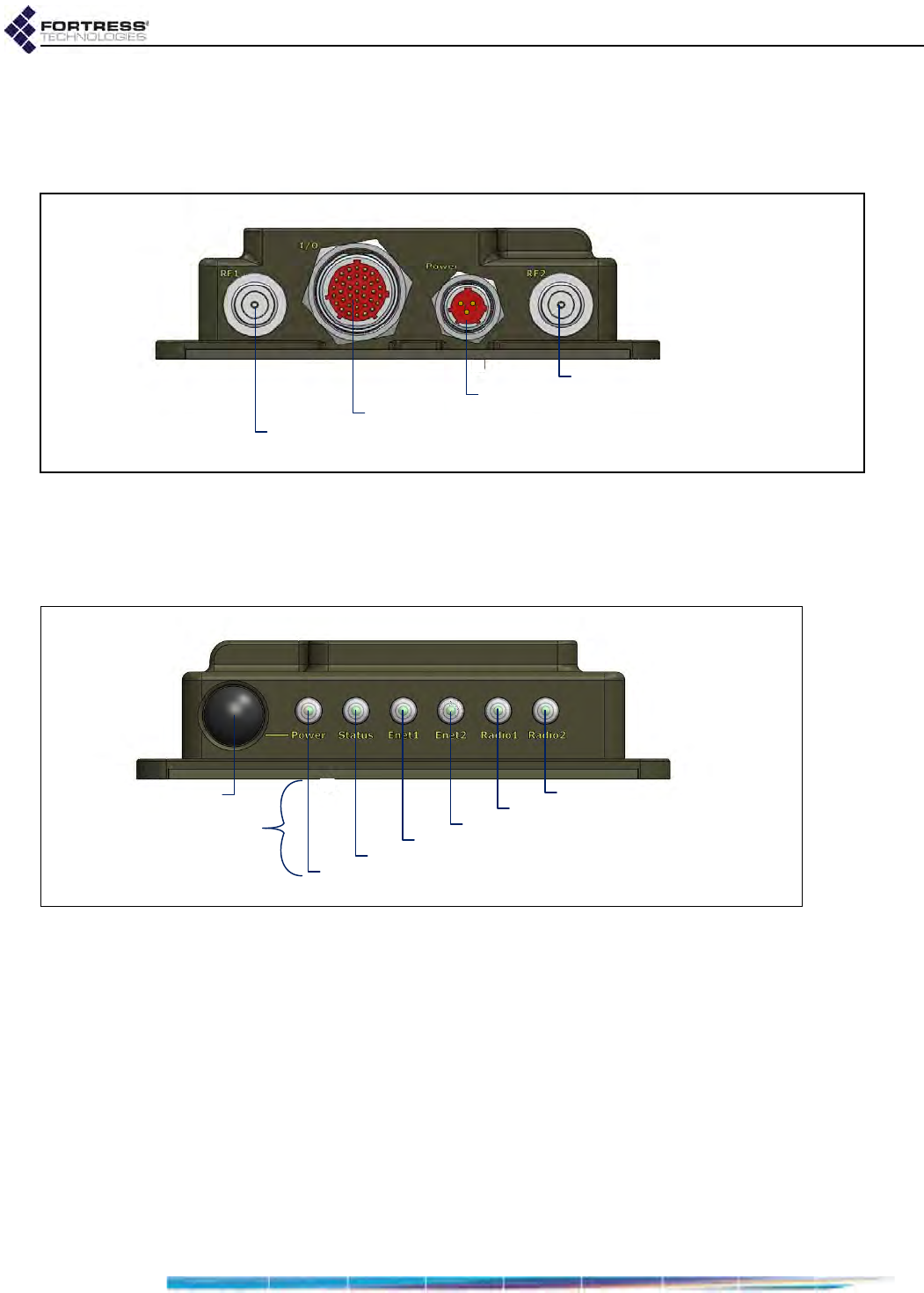
1 Port Locations
The ES820 Bridge’s power inlet, input/output control connector,
and antenna ports are located on the back panel, shown below.
Figure 1 ES820 Back-Panel Port Locations
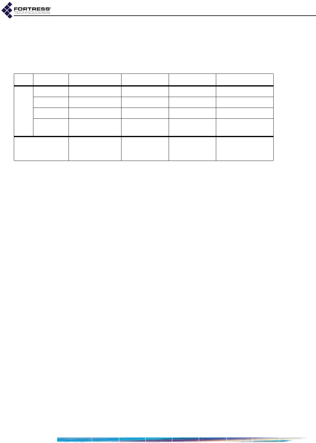
2LED Indicators
The ES820 Bridge’s front panel features six system LEDs.
Figure 2 ES820 Front-Panel Power Control and LEDs
Power
can exhibit:
solid green - Bridge is powered on and operating normally.
off - Bridge is powered off.
slow-flash green - Bridge is booting.
Status
can exhibit:
intermittent green - Cleartext is passing on an encrypted
port.
Ethernet1
and
Ethernet2
can exhibit:
solid green - Link has been established.
intermittent green - Traffic is passing on the port.
antenna port Radio 1
antenna port Radio 2
DC power inlet
I/O control connector
Radio 2
Radio 1
Ethernet port 1
Ethernet port 2
Status
Power
Power On/Off
LEDs
ES820 Bridge: Hardware
2
Radio1
and
Radio2
can exhibit:
solid green - Radio is on.
intermittent green - Radio is passing traffic.
off - Radio is off or Bridge’s RF Kill function is enabled.
3 Chassis and I/O Controls
The single front-panel button powers the ES820 Bridge ON
and OFF.
If the Bridge is off, press the Power button to turn it on.
The Power LED will slow-flash green while the Bridge
boots, then light solid green for normal operation.
or
If the Bridge is on, press the Power button to turn it off.
The Power LED will go dark.
Reboot (hard boot) the ES820 by powering it off and back on
again (described above).
The power button is tied to pin 33 or the Bridge’s 37-pin I/O
connector, which is a power control line. Both switches must be
OFF to power the ES820 off.
There are four control lines in addition to Power, described in
Section 4, below.
4Radios
The ES820 Bridge contains two radios:
The antenna ports on the ES820 back panel correspond to
these radio numbers as shown in Figure 1.
The last two LEDs on the right of the ES820 front panel
correspond to the radios as shown in Figure 2.
color behavior Power Status Enet1/Enet2 Radio1/Radio2
green
solid normal operation - link established radio ON
slow flash booting - - -
fast flash --- -
intermittent -cleartext on
encrypted port passing traffic passing traffic
off powered OFF --
radio OFF
or
RF Kill enabled
Radio 1 - 802.11a/b/g/n radio
Radio 2 - high power 802.11a/n radio
ES820 Bridge: Hardware
3
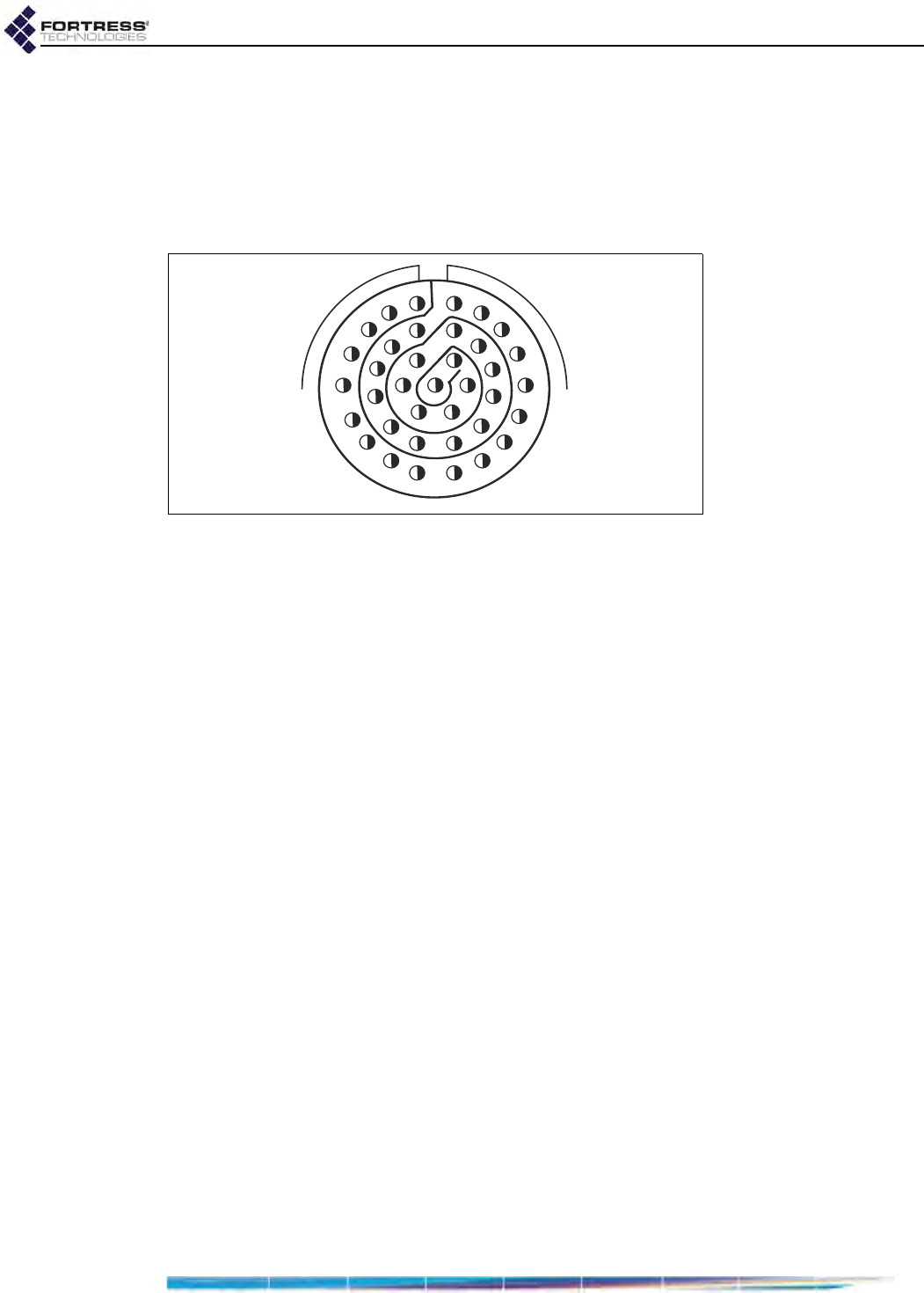
5 37-Pin Input/Output Connector
The connector on the rear panel of the ES820 provides all non-
radio input/output for the unit. In order to connect to the ES820,
a cable with a matching connector must be made, using the
required to connector type:
Amphenol MILDTL-D38999 / 26MD35PN
Figure 3. MIL-DTL-38999 Series III TV Shell/Insert 15-35 (socket)
Table 1 defines the pin-out required for the ES820 cable
connector. Most definitions are standard (ex., Ethernet, serial,
and USB). Five pins are unique to the ES820:
Power (pin 33 - active lo) - powers the ES820 on and off.
When this pin is toggled lo, the unit is permitted to power up
and boot. The switch state is tied to the chassis ON/OFF
switch: both switches must be OFF to turn the unit off. Tie
this pin to a toggle switch.
Blackout (pin 24 - active lo) - controls blackout mode, which
turns all chassis LEDs OFF. When this pin is held lo, all of
the LEDs on the box are dark at all times. When the pin is
not held lo, LEDs revert to normal operation. This pin would
commonly be tied to a toggle switch.
RF Kill (pin 22 - active lo) - controls the RF Kill feature,
which turns all radio transmission OFF. When this pin is
held lo, all RF emissions are suppressed. When the pin is
not held lo, radios revert to normal operation, as defined by
the current configuration of the ES820. This pin would
commonly be tied to a toggle switch.
Reset (pin 23 - active on falling edge) - reboots the box.
Resetting is equivalent to power cycling the ES820. The
reset function is immediate: all current operations are
stopped and the ES820 restarts from the initial power-on
state. This pin would commonly be tied to a push button.
Zeroize (pin 32 - active on rising edge) - restores the
configuration to factory defaults. This pin activates on the
rising edge of the signal. The zeroize function is immediate
when the ES820 is powered on. If the ES820 is powered off
1
21 31
11

ES820 Bridge: Hardware
4
when the zeroize is pressed, the function is executed as
soon as power is applied. This pin would commonly be tied
to a push button.
The 37-pin connector provides support for six LEDs, five
controls, two Ethernet ports, one USB port, and one RS232
COM port.
Table 1. ES820 37-Pin I/O Connector Pin-Outs
pin signal dir description
1GND - USB pin 4 Ground
2USB D+ Bi USB Data+ pin3, twisted pair+
3USB D- Bi USB Data- pin2, twisted pair-
4USB Vcc - USB pin1 Vcc (5V), up to 200mA
5Enet2 Link/Act LED Out LED2-, active Lo (8mA @2V diode)
6Radio2 LED Out LED3-, active Lo (8mA @2V diode)
7Radio1 LED Out LED4-, active Lo (8mA @2V diode)
8Status LED Out LED5- active Lo (8mA @2V diode)
9Power LED Out LED6- active Lo (8mA @2V diode)
10 LED Power - 3.3V through 10 ohms, 48 mA max, 330mA shorted;
Connect to the six LED+ pins
11 Enet2 D- -Enet 2- RJ45 pin 7 Cat5 twisted pair4
12 Enet2 RX- In Enet 2- RJ45 pin 6 Cat5 twisted pair2
13 Enet2 TX+ Out Enet 2- RJ45 pin 1 Cat5 twisted pair1
14 Enet2 TX- Out Enet 2- RJ45 pin 2 Cat5 twisted pair1
15 Enet1 D- -Enet 1- RJ45 pin 7 Cat5 twisted pair4
16 Enet1 RX- In Enet 1- RJ45 pin 6 Cat5 twisted pair2
17 Enet1 RX+ In Enet 1- RJ45 pin 3 Cat5 twisted pair2
18 Enet1 TX- Out Enet 1- RJ45 pin 2 Cat5 twisted pair1
19 GND - COM, RS232 Ground (Monitor Port)
20 COM TXD Out COM, RS232 Xmt (Monitor Port)
21 Enet1 Link/Act LED Out LED1- , active Lo (8mA @2V diode)
22 RF Kill_n (Toggle) In SW1, RFKILL, active Lo
23 Reset_n (PB) In SW3, Reset, active on falling edge
24 Blackout_n (Toggle) In SW5, Blackout, active Lo
25 Enet2 D+ -Enet 2- RJ45 pin 8 Cat5 twisted pair4
26 Enet2 RX+ In Enet 2- RJ45 pin 3 Cat5 twisted pair2
27 Enet2 C+ -Enet 2- RJ45 pin 4 Cat5 twisted pair3
28 Enet1 D+ - Enet 1- RJ45 pin 8 Cat5 twisted pair4
29 Enet1 C- -Enet 1- RJ45 pin 5 Cat5 twisted pair3
30 Enet1 TX+ Out Enet 1- RJ45 pin 1 Cat5 twisted pair1
31 COM RXD In COM, RS232 Rcv (Monitor Port)
32 Zeroize (PB) In SW2, Zeroize, active on rising edge
33 Power_n (Toggle) In SW4, Power on, active Lo
34 Enet2 C- - Enet 2- RJ45 pin 5 Cat5 twisted pair3
35 GND - Ground
36 Enet1 C+ - Enet 1- RJ45 pin 4 Cat5 twisted pair3
37 GND - Ground
ES820 Bridge: Hardware
5
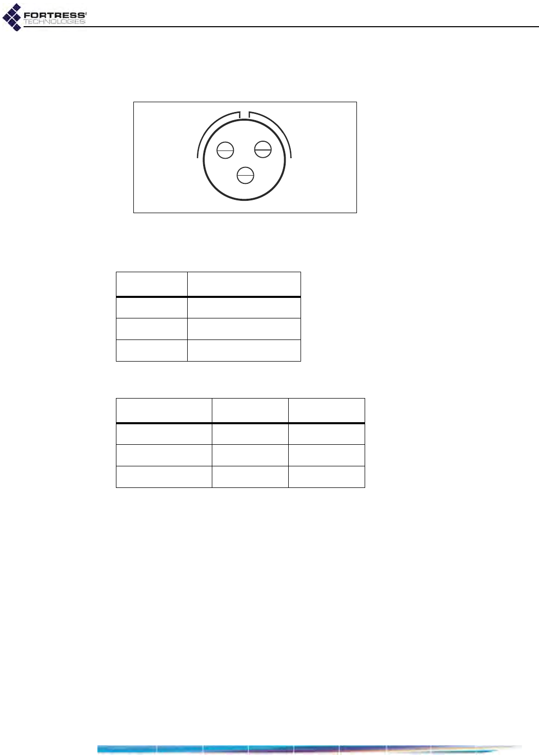
6 3-Pin DC Input Connector
The Bridge uses a 3-pin connector to input power.
Figure 4 3-pin Power Connector Pins
Table 2 shows the power connector pin-outs.
7 Dimensions and Weight
The ES820 weighs 2 lbs 8 oz (1.13 kg).
CA
B
Table 2. ES820 DC Power Connector Pin-Outs
pin signal
A+9 to 30 VDC
BN/C
CGND
dimension inches centimeters
height 1.75 4.44
width 6.85 17.4
depth 7.29 18.52