FreeWave Technologies 6231812519 900 MHz Modular spread spectum transmitter User Manual FreeWave Technologies Inc
FreeWave Technologies Inc. 900 MHz Modular spread spectum transmitter FreeWave Technologies Inc
UserManual.wiki
>
FreeWave Technologies
>
6231812519 User Manual
>
users manual
Contents
1.
manual instruction manual
2.
users manual
3.
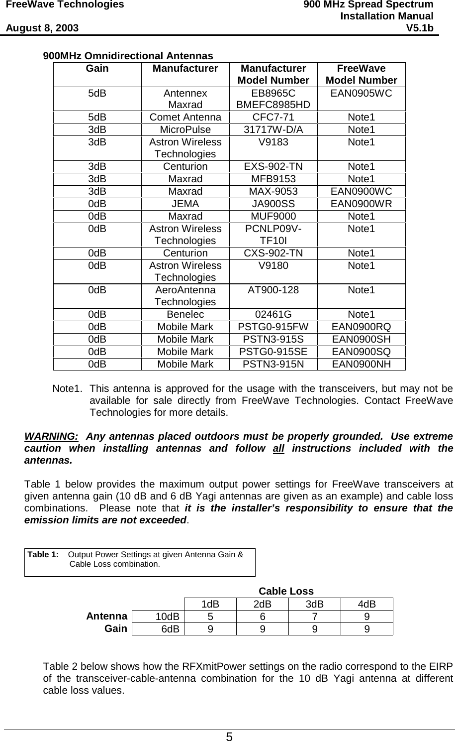
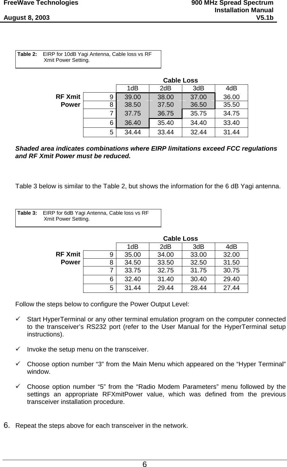
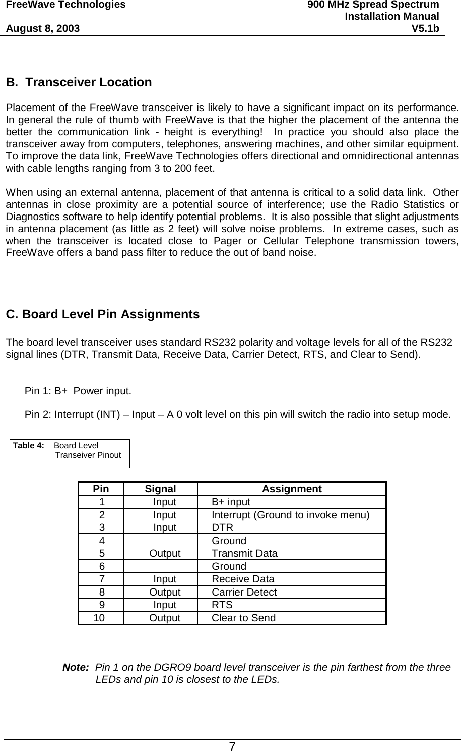
Users Manual
4.
Users Manual per CRN30797
users manual
Navigation menu
Upload a User Manual
Namespaces
Wiki Guide
HTML
PDF
Info
Views
User Manual
Discussion / Help
Navigation