FreeWave Technologies 6231812519 900 MHz Modular spread spectum transmitter User Manual FreeWave Technologies Inc
FreeWave Technologies Inc. 900 MHz Modular spread spectum transmitter FreeWave Technologies Inc
Contents
users manual

FreeWave Technologies
August 8, 2003
900 MHz Spread Spectrum
Installation Manual
V5.1b
FreeWave Technologies, Inc.
900 MHz Wireless Modem
Installation Guide
This installation guide covers all models of the FreeWave Technologies 900 MHz spread
spectrum transceiver sold under FCC ID KNY-6231812519.
All transceiver models sold under FCC ID KNY-6231812519 must be installed
professionally. This transceiver is only approved for use when installed in devices
produced by FreeWave Technologies or third party OEMs approved by FreeWave
Technologies. The antenna(s) to be used must be installed to provide a separation
distance of at least 23cm from all persons and must not be co-located or operating
in conjunction with any other antenna or transmitter. This transceiver must be
installed in a NEMA enclosure.
1

FreeWave Technologies
August 8, 2003
900 MHz Spread Spectrum
Installation Manual
V5.1b
FCC Notification
This device complies with part 15 of the FCC rules. Operation is subject to
the following two conditions: 1) This device may not cause harmful
interference and 2) this device must accept any interference received,
including interference that may cause undesired operation.
This device must be operated as supplied by FreeWave Technologies, Inc.
Any changes or modifications made to the device without the express written
approval of FreeWave Technologies may void the user's authority to operate
the device.
CAUTION: This device has a maximum transmitted output power of 955mW. It is
required that the transmit antenna be kept at least 23 cm away from
nearby persons to satisfy FCC RF exposure requirements.
Note: This equipment has been tested and found to comply with the limits for a Class B digital
device, pursuant to part 15 of the FCC Rules. These limits are designed to provide reasonable
protection against harmful interference in a residential installation. This equipment generates,
uses and can radiate radio frequency energy and, if not installed and used in accordance with the
instructions, may cause harmful interference to radio communications. However, there is no
guarantee that interference will not occur in a particular installation. If this equipment does cause
harmful interference to radio or television reception, which can be determined by turning the
equipment off and on, the user is encouraged to try to correct the interference by one or more of
the following measures:
♦ Reorient or relocate the receiving antenna.
♦ Increase the separation between the equipment and receiver.
♦ Connect the equipment into an outlet on a circuit different from that to which the receiver is
connected.
♦ Consult the dealer or an experienced radio/TV technician for help.
Note: Whenever any FreeWave Technologies module is placed inside an enclosure a label
must be placed on the outside of that enclosure which includes the module's FCC ID.
UL Notification
Model# FGRO9CSU is suitable for use in Class 1, Division 2,
Groups A, B, C, and D or non-hazardous locations only. Input
voltage for Model# FGRO9CSU is 6 to 30 volts DC.
Model# DGRO9RFS is suitable for use in Class 1, Division 2, Groups A, B, C,
and D or non-hazardous locations only.
2
FreeWave Technologies
August 8, 2003
900 MHz Spread Spectrum
Installation Manual
V5.1b
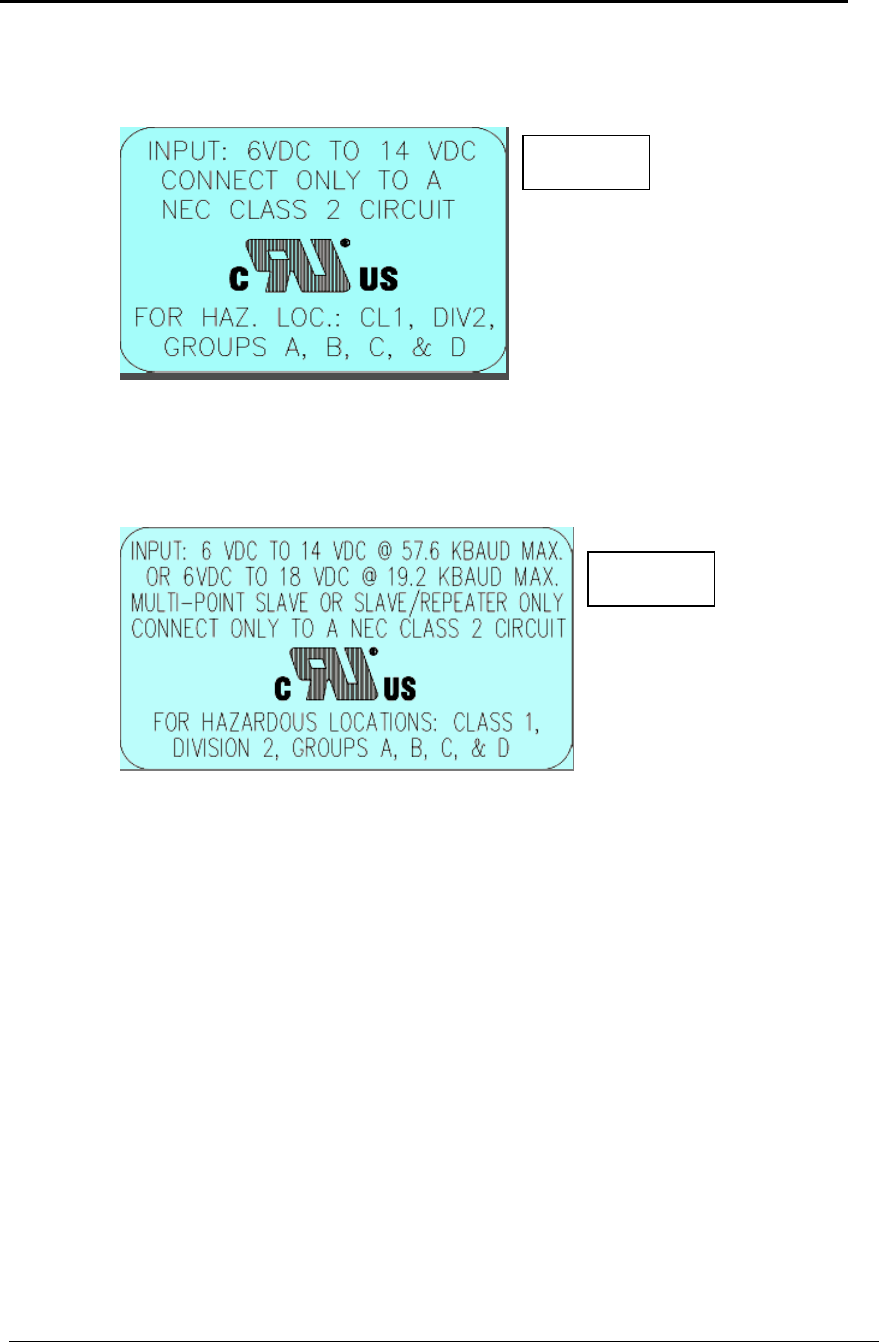
Input voltages for Model# DGRO9RFS are determined by the label on the bottom of
the board. If the board has Label A shown below the input voltage is 6 to 14 volts
DC.
Class 1 Div 2
Label A
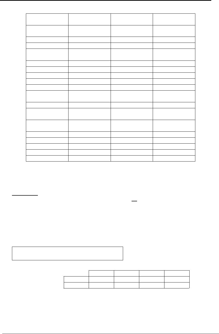
If the board has Label B shown below the input voltage is 6 to 14 volts DC at a
maximum baud rate of 57.6 KBaud or 6 to 18 volts DC at a maximum baud rate of
19.2 KBaud, operation mode of multipoint slave or multipoint slave/repeater only.
Class 1 Div 2
Label B
3

FreeWave Technologies
August 8, 2003
900 MHz Spread Spectrum
Installation Manual
V5.1b
A. Transceiver installation steps
To install the DGR and FGR series transceivers, follow the basic steps given below.
1. Mount the transceiver to the flat, stable surface using mounting holes in the corners of the
transceiver. Transceiver models sold under FCC ID KNY-6231812519 are to be installed
professionally in NEMA enclosures.
2. Install the antenna and connect the antenna feedline to the transceiver. If you are installing a
directional antenna, preset the antenna’s direction appropriately. The antenna must be
professionally installed on fixed-mounted permanent outdoor structures for satisfying RF
exposure requirements.
3. Connect a computer to the transceiver’s RS232 port (please refer to the part C of this
addendum for more information about the transceiver’s pin assignment). This computer will
be used to set the radio’s configurations.
4. Install the power for the radio.
5. Set the radio configuration according to the system topology and data terminal equipment
requirements. Default transceiver settings allow user to do a quick installation without major
changes in transceiver’s configuration. But there is one parameter that must be considered
for a new installation – transceiver’s power output settings.
Transceiver output power level must be set according to the tables given below to satisfy
FCC maximum EIRP requirement. Per FCC regulations, any antenna used with FreeWave
transceivers must either be one of the approved antennas shown below or an antenna with
comparable performance parameters. FreeWave Technologies offers a variety of
omnidirectional and directional external antennas, with both bracket and magnetic mounts.
The complete list of antennas available from FreeWave Technologies including antenna
gains, antenna manufacturer’s information and antenna’s characteristics is shown below:
The following antennas are approved for use with FreeWave transceivers:
900MHz Directional Antennas
Gain Manufacturer Manufacturer
Model Number FreeWave
Model Number
10dB Mobile Mark YAG10-915N EAN0900YB
10dB Larsen YA0006 EAN0900YA
6dB Mobile Mark YAG6-915N EAN0906YB
6dB Larsen YA6-900 EAN0906YA
4
FreeWave Technologies
August 8, 2003
900 MHz Spread Spectrum
Installation Manual
V5.1b
900MHz Omnidirectional Antennas
Gain Manufacturer Manufacturer
Model Number FreeWave
Model Number
5dB Antennex
Maxrad EB8965C
BMEFC8985HD EAN0905WC
5dB Comet Antenna CFC7-71 Note1
3dB MicroPulse 31717W-D/A Note1
3dB Astron Wireless
Technologies V9183 Note1
3dB Centurion EXS-902-TN Note1
3dB Maxrad MFB9153 Note1
3dB Maxrad MAX-9053 EAN0900WC
0dB JEMA JA900SS EAN0900WR
0dB Maxrad MUF9000 Note1
0dB Astron Wireless
Technologies PCNLP09V-
TF10I Note1
0dB Centurion CXS-902-TN Note1
0dB Astron Wireless
Technologies V9180 Note1
0dB AeroAntenna
Technologies AT900-128 Note1
0dB Benelec 02461G Note1
0dB Mobile Mark PSTG0-915FW EAN0900RQ
0dB Mobile Mark PSTN3-915S EAN0900SH
0dB Mobile Mark PSTG0-915SE EAN0900SQ
0dB Mobile Mark PSTN3-915N EAN0900NH
Note1. This antenna is approved for the usage with the transceivers, but may not be
available for sale directly from FreeWave Technologies. Contact FreeWave
Technologies for more details.
WARNING: Any antennas placed outdoors must be properly grounded. Use extreme
caution when installing antennas and follow all instructions included with the
antennas.
Table 1 below provides the maximum output power settings for FreeWave transceivers at
given antenna gain (10 dB and 6 dB Yagi antennas are given as an example) and cable loss
combinations. Please note that it is the installer’s responsibility to ensure that the
emission limits are not exceeded.
Table 1: Output Power Settings at given Antenna Gain &
Cable Loss combination.
Cable Loss
1dB 2dB 3dB 4dB
Antenna 10dB 5 6 7 9
Gain 6dB 9 9 9 9
Table 2 below shows how the RFXmitPower settings on the radio correspond to the EIRP
of the transceiver-cable-antenna combination for the 10 dB Yagi antenna at different
cable loss values.
5
FreeWave Technologies
August 8, 2003
900 MHz Spread Spectrum
Installation Manual
V5.1b
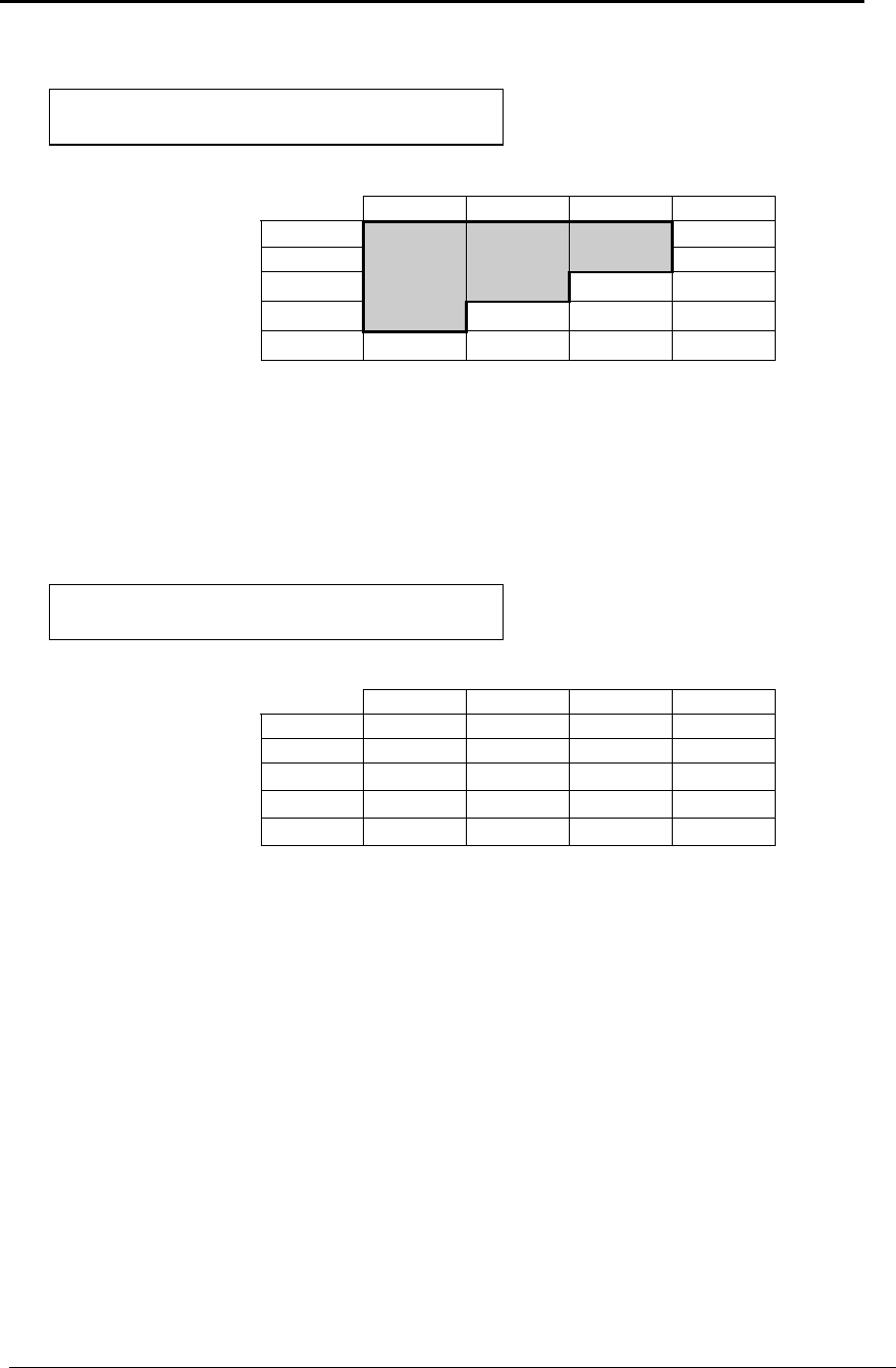
Table 2: EIRP for 10dB Yagi Antenna, Cable loss vs RF
Xmit Power Setting.
Cable Loss
1dB 2dB 3dB 4dB
RF Xmit 9 39.00 38.00 37.00 36.00
Power 8 38.50 37.50 36.50 35.50
7 37.75 36.75 35.75 34.75
6 36.40 35.40 34.40 33.40
5 34.44 33.44 32.44 31.44
Shaded area indicates combinations where EIRP limitations exceed FCC regulations
and RF Xmit Power must be reduced.
Table 3 below is similar to the Table 2, but shows the information for the 6 dB Yagi antenna.
Table 3: EIRP for 6dB Yagi Antenna, Cable loss vs RF
Xmit Power Setting.
Cable Loss
1dB 2dB 3dB 4dB
RF Xmit 9 35.00 34.00 33.00 32.00
Power 8 34.50 33.50 32.50 31.50
7 33.75 32.75 31.75 30.75
6 32.40 31.40 30.40 29.40
5 31.44 29.44 28.44 27.44
Follow the steps below to configure the Power Output Level:
Start HyperTerminal or any other terminal emulation program on the computer connected
to the transceiver’s RS232 port (refer to the User Manual for the HyperTerminal setup
instructions).
Invoke the setup menu on the transceiver.
Choose option number “3” from the Main Menu which appeared on the “Hyper Terminal”
window.
Choose option number “5” from the “Radio Modem Parameters” menu followed by the
settings an appropriate RFXmitPower value, which was defined from the previous
transceiver installation procedure.
6. Repeat the steps above for each transceiver in the network.
6
FreeWave Technologies
August 8, 2003
900 MHz Spread Spectrum
Installation Manual
V5.1b
B. Transceiver Location
Placement of the FreeWave transceiver is likely to have a significant impact on its performance.
In general the rule of thumb with FreeWave is that the higher the placement of the antenna the
better the communication link - height is everything! In practice you should also place the
transceiver away from computers, telephones, answering machines, and other similar equipment.
To improve the data link, FreeWave Technologies offers directional and omnidirectional antennas
with cable lengths ranging from 3 to 200 feet.
When using an external antenna, placement of that antenna is critical to a solid data link. Other
antennas in close proximity are a potential source of interference; use the Radio Statistics or
Diagnostics software to help identify potential problems. It is also possible that slight adjustments
in antenna placement (as little as 2 feet) will solve noise problems. In extreme cases, such as
when the transceiver is located close to Pager or Cellular Telephone transmission towers,
FreeWave offers a band pass filter to reduce the out of band noise.
C. Board Level Pin Assignments
The board level transceiver uses standard RS232 polarity and voltage levels for all of the RS232
signal lines (DTR, Transmit Data, Receive Data, Carrier Detect, RTS, and Clear to Send).
Pin 1: B+ Power input.
Pin 2: Interrupt (INT) – Input – A 0 volt level on this pin will switch the radio into setup mode.
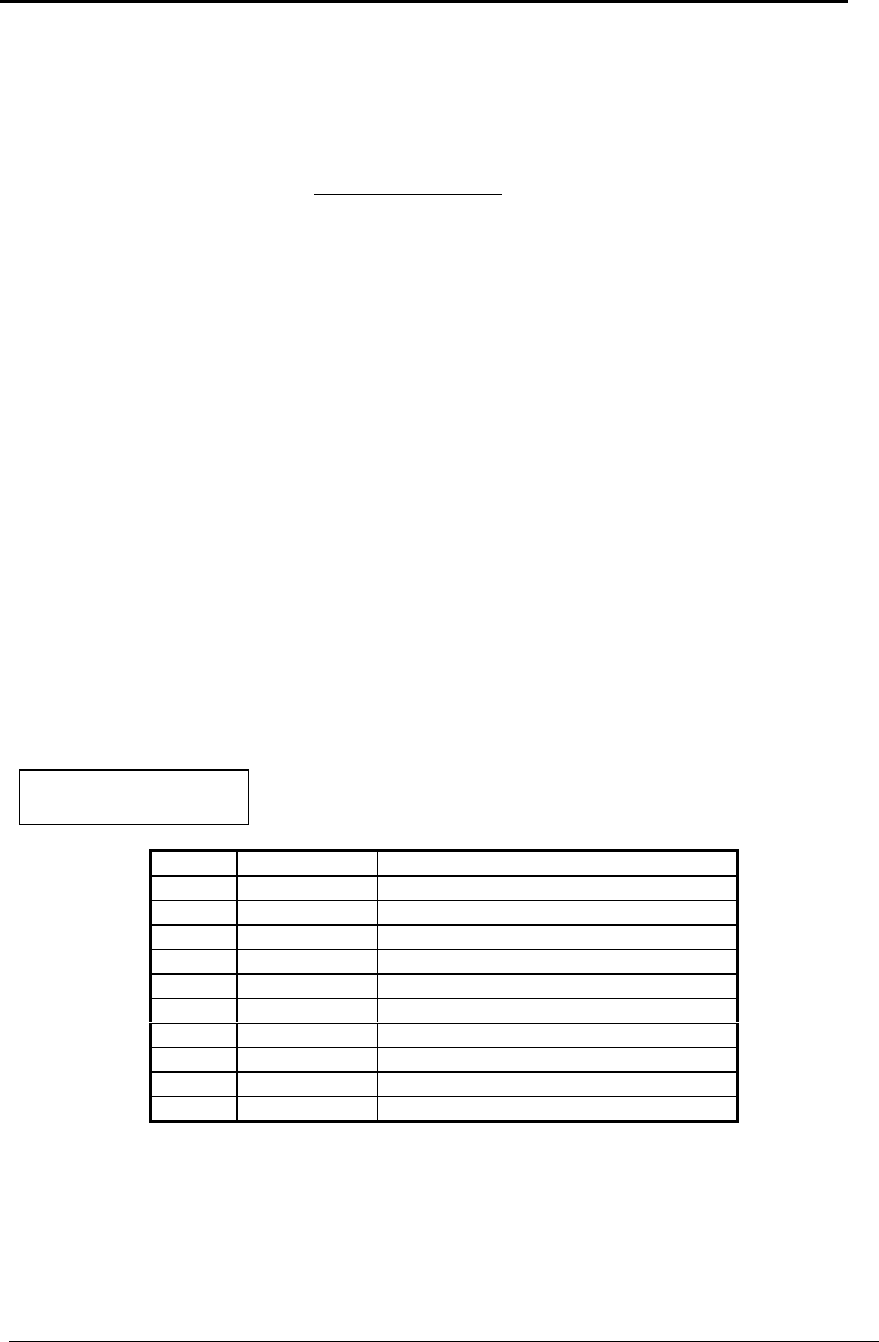
Table 4: Board Level
Transeiver Pinout
Pin Signal Assignment
1 Input B+ input
2 Input Interrupt (Ground to invoke menu)
3 Input DTR
4 Ground
5 Output Transmit Data
6 Ground
7 Input Receive Data
8 Output Carrier Detect
9 Input RTS
10 Output Clear to Send
Note: Pin 1 on the DGRO9 board level transceiver is the pin farthest from the three
LEDs and pin 10 is closest to the LEDs.
7

FreeWave Technologies
August 8, 2003
900 MHz Spread Spectrum
Installation Manual
V5.1b
D. Power Connection
The DGR and FGR series transceivers can be operated from any well-filtered DC power source,
input voltages vary by model. The power source should be capable of providing at least 0.8
amperes of continuous current. The pin #1 of the 10-pin connector on the transceiver is the
positive lead; pin #4 or pin #6 of this connector should be as a negative lead.
Transceiver is designed to operate in negative ground systems only.
8