Furuno USA 9ZWFM8900S GMDSS VHF User Manual
Furuno USA Inc GMDSS VHF
UserManual.wiki
>
Furuno USA
>
9ZWFM8900S User Manual
>
usermanual part 3
Contents
1.
users manual part 1
2.
users manaul part 2
3.
usermanual part 3
usermanual part 3
Navigation menu
Upload a User Manual
Namespaces
Wiki Guide
HTML
PDF
Info
Views
User Manual
Discussion / Help
Navigation
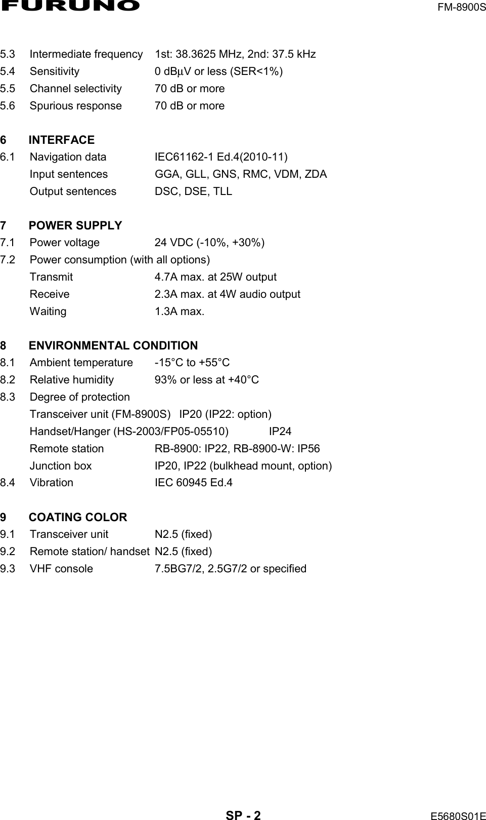
![5. MENU OPERATION5-21Rotate the CHANNEL/ENTER knob to select [AUDIO] on the [MENU] screen then push the knob.5.20 Alarm ListsThe [ALARM] menu shows all currently violated alarms. When an error occurs, a pop-up message and a flashing error icon appear on the screen. Press the CANCEL key to close the pop-up message and stop the flashing of the error icon. When the error is removed, the error icon disappears.Rotate the CHANNEL/ENTER knob to select [ALARM] on the [MENU] screen then push the knob. The following screen appears.There are three kinds of errors: [TX PLL UNLOCK], [RX PLL UNLOCK], [DSC PLL UNLOCK].Errors are displayed in the order shown above, not in the order of occurrence. An error is deleted from the list when the cause for the error is removed.These alarms are listed when the following messages appear.Default: [2]Turn beep on (setting: [1] - [3]) or off (setting: [0]) when a key is pressed.Default: [MUTE]Turn the speaker on or off when the handset is off hook.Rotate the CHANNEL/ENTER knob to set volume then push the knob.Default: [OFF]Adjust tone quality for speaker.Turn the speakers except in-use one on or off. [PUBLIC]: On, [PRIVATE]: OffError icon](https://usermanual.wiki/Furuno-USA/9ZWFM8900S.usermanual-part-3/User-Guide-1778063-Page-1.png)
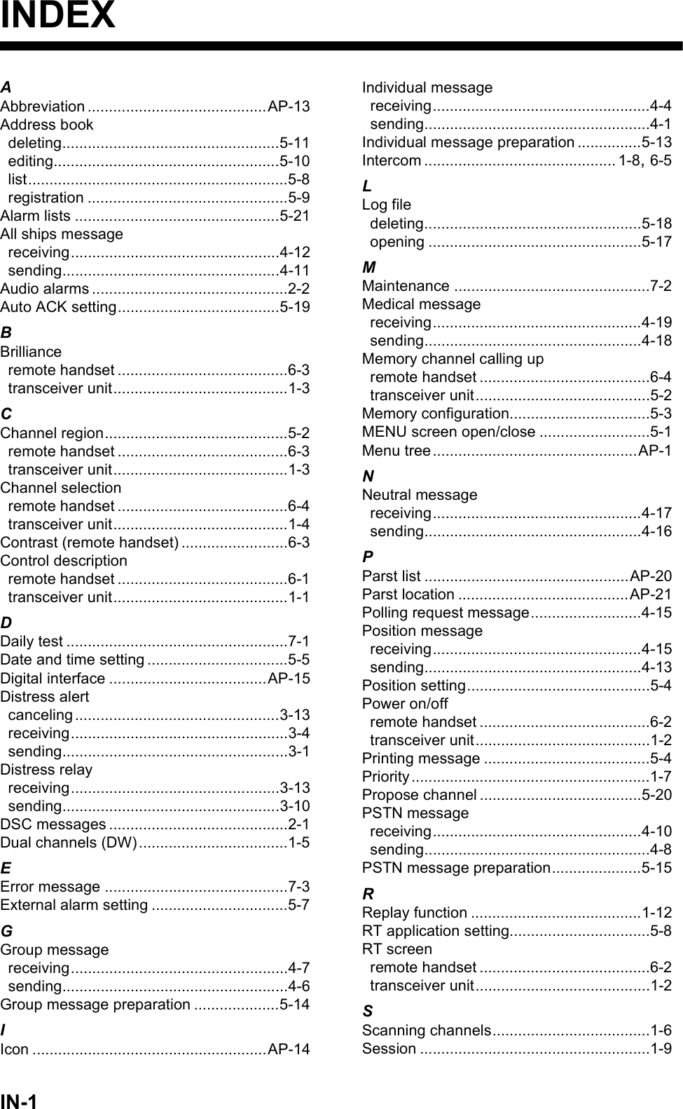
![6. REMOTE HANDSET6-26.2 How to Turn On/Off the PowerA handset does not have a power key. Turn on or off the power from the transceiver unit.6.3 Radiotelephone (RT) ScreenBelow are the radiotelephone (RT) screens on the remote handset.MENU key Opens/closes the menu.0 to 9 keys • Enters the channel on the RT screen.• Selects the menu items.CONTRAST key Short press: Opens the contrast setup screen. Press the S or T key to adjust the contrast.Long press (more than three seconds): Restores the contrast to the de-fault setting.BRILL key Opens the brill setup screen. Press the S or T key to adjust the brill. You can also use the BRILL key.No. Meaning1 RX signal strength (This icon does not appear while transmitting.)2 Output power ([HI]: High, [LO]: Low)3 Channel type ([SIMP]: Simplex, [DUP]: Duplex) 4 Spinner rotates when the equipment is functioning normally.5 Channel region ([INT’L], [USA], [CANADA], [INLAND-W], [PRIVATE])6 Channel7Loudspeaker on ( ) or off ( )8 Volume for loudspeaker (0 to 10)9 Squelch level (0 to 10, AUTO (Indication is [SQA].))10 Terminal ID ([L]: Left wing handset, [R]: Right wing handset, [1] to [4]: Remote handset 1 to 4)Control Function21345910678DW screenCommon RT screenScan screenWhen no terminal has operation right and a remote handset is off hook, the following screen appears. A remote handset can get the operation right if you hook on then hook off.](https://usermanual.wiki/Furuno-USA/9ZWFM8900S.usermanual-part-3/User-Guide-1778063-Page-4.png)
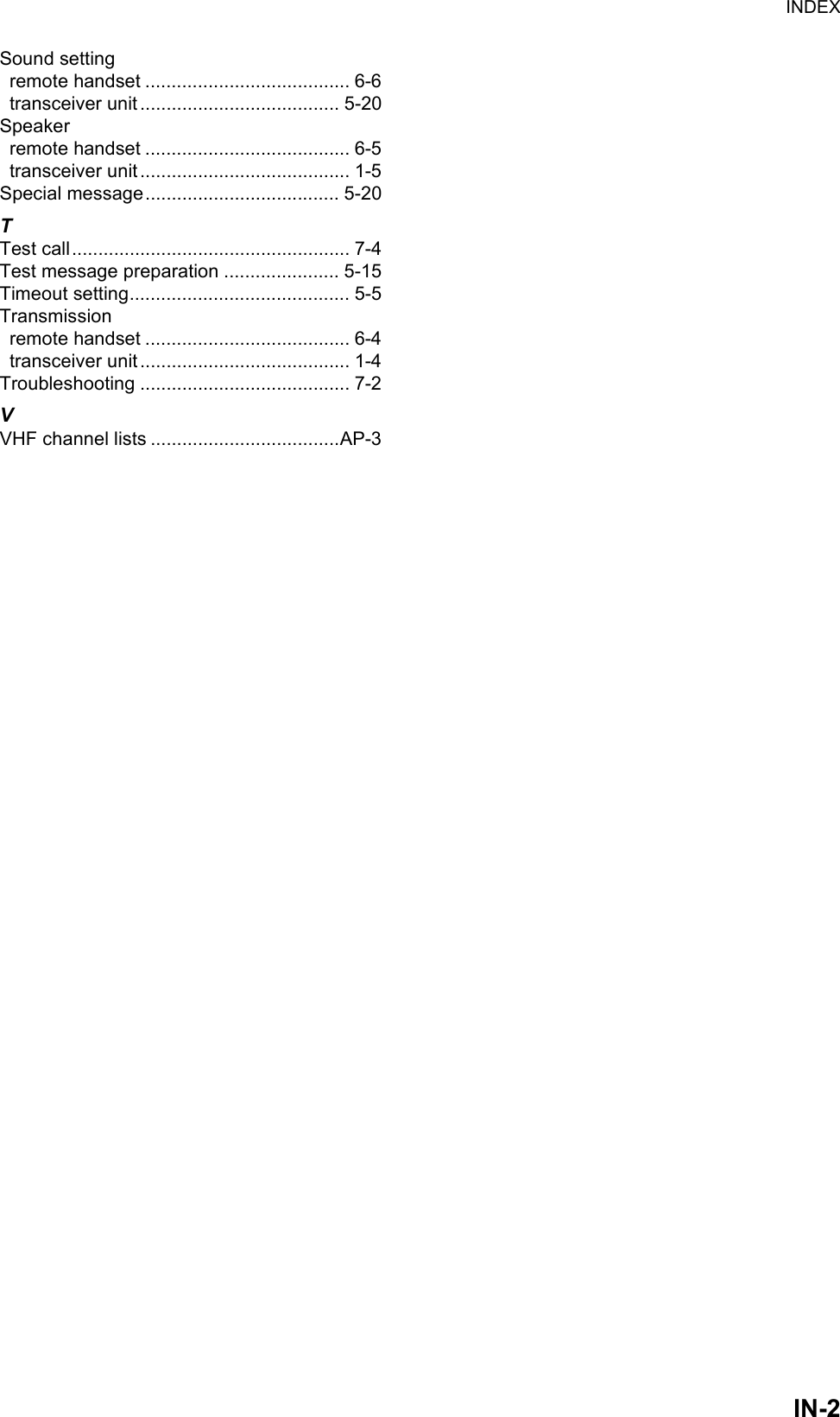
![6. REMOTE HANDSET6-36.4 How to Adjust the Brilliance and ContrastYou can adjust the brilliance of the display and the panel for each remote handset sep-arately. Also, you can adjust the contrast for each remote handset.Brilliance1. Press the BRILL key to show the [BRILL] setting window.2. Press the S or T key to adjust the brilliance.3. Press the ENTER key to save the settings and close the window. To cancel the settings, press the CANCEL key in-stead of the ENTER key to close the window.Note: The [BRILL] setting window automatically closes when there is no menu oper-ation for three seconds.Contrast1. Press the CONTRAST key to show the [CONTRAST] set-ting window.2. Press the S or T key to adjust the contrast.3. Press the ENTER key to save the settings and close the window. To cancel the settings, press the CANCEL key in-stead of the ENTER key to close the window.Note: The [CONTRAST] setting window automatically closes when there is no menu operation for three seconds.6.5 How to Select the Channel Region, ChannelChannel region1. Press the MENU key to open the [MENU] screen.2. Press the S or T key to select [REGION] then press the ENTER key.3. Press the S or T key to select the channel mode desired then press the ENTER key. The following modes are available.• [INT’L]: International mode• [USA]: USA mode• [CANADA]: CANADA mode• [INLAND-W]: Inland waterway mode• [PRIVATE]: Private channel](https://usermanual.wiki/Furuno-USA/9ZWFM8900S.usermanual-part-3/User-Guide-1778063-Page-5.png)
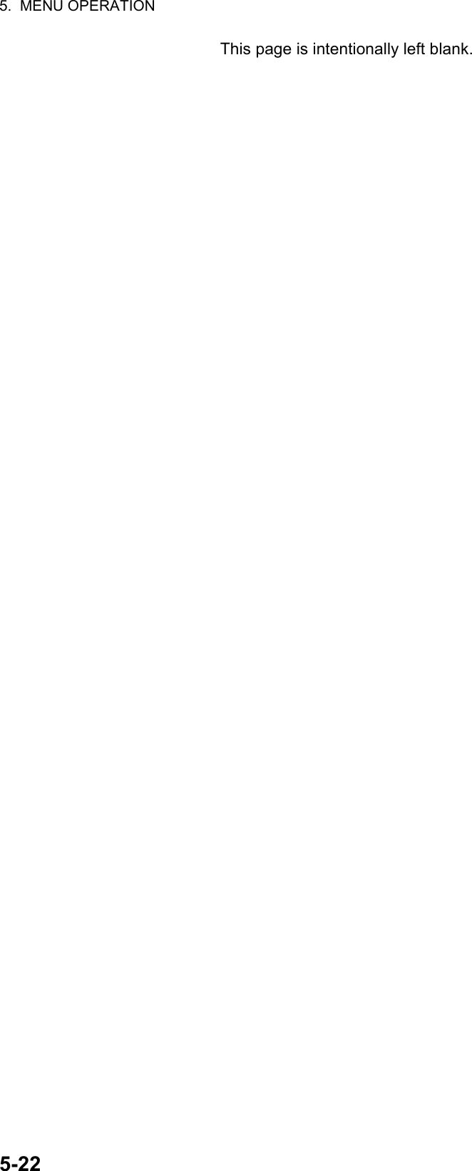
![6. REMOTE HANDSET6-4Note 1: Only permitted channel regions are displayed, which are set by the install-er of the equipment.Note 2: Private channels are available only where permitted by the authorities. The [USA], [CANADA], [INLAND-W], [PRIVATE] can also be set by a qualified service technician.ChannelThe channel can be set manually on the RT screen. Enter the channel by one of the methods below.Enter channel with the S or T key:Press the S or T key on the RT screen.Enter channel with the numeric keys:Use the numeric keys to enter channel on the RT screen. (It is not necessary to press the ENTER key after entering the channel; the setting is confirmed one second after it is entered.)Note: When the transceiver unit is in on hook condition, you can change the channel with the remote handset.Memory channelYou can easily call up a channel which you registered in the transceiver unit as a mem-ory channel (see section 5.4).1. Press the MENU key to open the [MENU] screen.2. Press the S or T key to select [MEMORY CH] then press the ENTER key.3. Press the S or T key to select [ON] or [OFF] then press the ENTER key.When you select [ON], "M" appears on the screen. On the RT screen, you can se-lect a memory channel by pressing the S or T key. The following figure shows the example for CH 10.6.6 TransmissionHow to transmitPress the PTT (Push-to-talk) switch on the handset to talk, and release it to listen for a response. "TX" appears at the top left-hand corner of the screen during transmis-sion.How to change the output powerPress the HI/LO key to change the output power to high and low alter-nately. "HI" or "LO" appears on the screen depending on your selection.Channel number“3” means that you turned 3 channels of the selected channel region to [ON] in the [MEMORY CONFIG] menu in the transceiver unit.](https://usermanual.wiki/Furuno-USA/9ZWFM8900S.usermanual-part-3/User-Guide-1778063-Page-6.png)
![6. REMOTE HANDSET6-56.7 How to Turn On/Off the LoudspeakerYou can turn the loudspeaker (other than DSC communication, error, and key beep) on or off.1. Press the SPK key to alternately disable or en-able the loudspeaker.2. To adjust the volume of the loudspeaker, press the VOL key. The screen changes as below.3. Press the S or T key to adjust the volume within three seconds. The time for re-verse highlighting is three seconds.6.8 Quick Selection of CH16Press the CH16 key to select CH16. The CH16 (156.8 MHz) is the international fre-quency for distress traffic and for calling by radiotelephone. The CH16 can also be used by ship stations for call and reply. To facilitate the reception of distress calls and distress traffic, all transmissions on CH16 should be kept to a minimum and should not exceed one minute. Before transmitting on the CH16, a station should listen on this frequency for a reasonable period to make sure that no distress traffic is being sent.6.9 IntercomThe built-in intercom permits voice communications between two control units. The combination of two controls is transceiver unit & remote handset, or remote handset & remote handset.CallingYou can call over the intercom only in off hook condition.1. Press the MENU key to open the [MENU] screen.2. Press the S or T key to select [INTERCOM] then press the ENTER key.3. Press the S or T key to select the called party’s control unit then press the ENTER key.The called party’s control unit and yours ring.To cancel calling, press the CANCEL key.Speaker ON Speaker OFFReverse highlighting](https://usermanual.wiki/Furuno-USA/9ZWFM8900S.usermanual-part-3/User-Guide-1778063-Page-7.png)
![6. REMOTE HANDSET6-64. When the called party picks up their handset, the screen as shown in the right figure appears. Start communica-tions.Note: You do not have to press the PTT switch to commu-nicate.5. Hang up the handset or press the CANCEL or the CH16 key to turn the intercom off. The RT screen appears.Answering1. The control unit rings and the following screen appears. To cancel reply, press the CANCEL key.2. Press the ENTER key with off hook condition or pick up the handset with on hook condition to start communications.3. Hang up the handset or press the CANCEL key to turn the intercom off. The RT screen appears.Earpiece volumeYou can adjust the volume of the earpiece during intercom communication by pressing the S or T key. After intercom communication, the earpiece volume is reverted to the setting value you set on [EARPIECE LEVEL] (see section 6.11).Note: Neither key click nor key error sounds during intercom communication.6.10 How to Change the Terminal ID1. Turn off the remote handset by the transceiver unit.2. While you hold the MENU key, turn on the remote handset by the transceiver unit. The setting window for terminal ID appears.3. Enter the terminal ID, using the 1 to 6 keys, then press the ENTER key. Do not assign the same number to multiple remote stations.Note: Restart the remote handset by the transceiver unit after changing terminal ID.6.11 Audio settingThe [AUDIO] menu enables or disables key beep and adjusts the volume of the ear-piece and off hook loudspeaker.Key click1. Press the MENU key to open the [MENU] screen.Off hook condition On hook condition](https://usermanual.wiki/Furuno-USA/9ZWFM8900S.usermanual-part-3/User-Guide-1778063-Page-8.png)
![6. REMOTE HANDSET6-72. Press the S or T key to select [AUDIO] then press the EN-TER key.3. Press the S or T key to select [KEY CLICK VOLUME] then press the ENTER key.4. Press the S or T key to set the key click level (setting range: 0 (OFF), 1, 2 or 3).5. Press the ENTER key. To cancel the setting, press the CANCEL key.Earpiece volume1. Press the MENU key to open the [MENU] screen.2. Press the S or T key to select [AUDIO] then press the ENTER key.3. Press the S or T key to select [EARPIECE LEVEL] then press the ENTER key.Note: Neither key click nor key error sounds during the [EARPIECE LEVEL] display.4. Press the S or T key to set the earpiece volume level (setting range: 1 to 3).5. Press the ENTER key. To cancel the setting, press the CANCEL key.Off hook loudspeakerYou can set the loudspeaker on or off according to off hook condition.1. Press the MENU key to open the [MENU] screen.2. Press the S or T key to select [AUDIO] then press the ENTER key.3. Press the S or T key to select [OFF HOOK SPEAKER] then press the ENTER key.4. Press the S or T key to select [SP_ON] or [MUTE].[SP_ON]: Loudspeaker is activated when off hook.[MUTE]: Loudspeaker is deactivated when off hook.5. Press the ENTER key. To cancel the setting, press the CANCEL key.](https://usermanual.wiki/Furuno-USA/9ZWFM8900S.usermanual-part-3/User-Guide-1778063-Page-9.png)
![6. REMOTE HANDSET6-86.12 How to Test FM-8900S from a Remote Handset1. Press the MENU key to open the [MENU] screen.2. Press the S or T key to select [DAILY TEST] then press the ENTER key.3. Press the ENTER key to start the test. You can confirm the test results for FM-8900S with the 1 or 3 key.6.13 How to Display the Program Versions1. Press the MENU key to open the [MENU] screen.2. Press the S or T key to select [VERSION] then press the ENTER key. The pro-gram versions for FM-8900S and HS-8900 appear.6.14 Squelch• The squelch value is common to all remote handsets. If you change a squelch value for a remote handset, squelch values for all other remote handsets are changed ac-cordingly.• You can not change a squelch value for a remote handset while the squelch is being adjusted by another remote handset.• When the DW or scan is active, the squelch value from the terminal (transceiver unit or remote handset) that initiated the DW or scan is used.This item is not displayed when there is no alarm unit.Press the 3 key for the next page and the 1 key for the previous page.These items are displayed only when entering own ship’s MMSI.](https://usermanual.wiki/Furuno-USA/9ZWFM8900S.usermanual-part-3/User-Guide-1778063-Page-10.png)
![7-17. MAINTENANCE &TROUBLESHOOTING7.1 Daily TestDo the daily test to check the radiotelephone for proper operation.Rotate the CHANNEL/ENTER knob to select [TEST] on the [MENU] screen then push the knob. The daily test starts. After the test is completed, the audio alarm sounds and the screen shown below appears. This screen shows:• Test date• Program version number• Test results for TX power, TX PLL, RX PLL, DSC PLL, DSC loopback, DSC routine, ROM, RAM, RTC, DSP, FPGA and alarm unit (only when connecting the alarm unit), shown as [OK] or [NG] (No Good). For NG, contact your dealer for advice. The DSC test checks, using a DSC signal, the encode and decode functions of the sig-nal processor.To print out the test result manually, press the 5 key. Automatic printing of the daily test is available. See section 5.5.Do not apply paint, anti-corrosive sealant or contact spray to plastic parts or equipment coating.Those items contain products that can damage plastic parts and equipment coating.ELECTRICAL SHOCK HAZARDDo not open the equipment.Only qualified personnel should work inside the equipment.WARNINGWARNINGNOTICEx xThis item is not available when not connecting the alarm unit.These items are not available when not enter-ing own ship’s MMSI.](https://usermanual.wiki/Furuno-USA/9ZWFM8900S.usermanual-part-3/User-Guide-1778063-Page-11.png)
![7. MAINTENANCE & TROUBLESHOOTING7-37.4 Warning and Caution MessagesThe table below shows error messages, their meanings, and remedies. To delete the messages, press the CANCEL key.Message Meaning RemedyTX PLL unlock. Transmission is dis-abled.Contact your dealer.TX PLL unlock error. Transmission is disabled.Contact your dealer.RX PLL unlock. Reception is dis-abled.Contact your dealer.DSC (CH70) PLL unlock. Contact your dealer.Position data is not input for ten min-utes.Note: This message does not ap-pear when [INPUT TYPE] in the [PO-SITION] menu is set to [MANUAL].Enter the position.Position data has not been updated for 4H.Enter the position.Position data has not been updated for 23.5H.Enter the position.You tried to send a DSC message but your MMSI has not been regis-tered in the equipment.Enter MMSI no. of your ship.Printer trouble. Cannot print. Check the printer (connection, power, paper).Communication between the trans-ceiver unit and a remote handset is lost for three seconds.Check the connection with the remote hand-set. If unsolved, con-tact your dealer.](https://usermanual.wiki/Furuno-USA/9ZWFM8900S.usermanual-part-3/User-Guide-1778063-Page-13.png)
![7. MAINTENANCE & TROUBLESHOOTING7-47.5 Test CallThis function sends a test signal to a coast or ship station. For that reason, it should not be executed unnecessarily. You can prepare a test call beforehand (see paragraph 5.14.5).1. Press the OTHER DSC MSG key to open the [COMPOSE MESSAGE].2. Rotate the CHANNEL/ENTER knob to select [MSG TYPE] then push the knob.3. Rotate the CHANNEL/ENTER knob to select [TEST MSG] then push the knob. [PRIORITY] is automatically set to [SAFETY].4. With [TO] selected, push the CHANNEL/ENTER knob.5. Rotate the CHANNEL/ENTER knob to select [DIRECT INPUT], [ADDRESS BOOK DATA] or [AIS TARGET DATA] then push the knob.[DIRECT INPUT]: Enter the MMSI of the station where to send the call then push the CHANNEL/ENTER knob.[ADDRESS BOOK DATA]: Select an MMSI from the [ADDRESS BOOK] (see section 5.13) then push the CHANNEL/ENTER knob.[AIS TARGET DATA]: Select an MMSI from the [AIS TARGET LIST] then push the CHANNEL/ENTER knob.6. With [GO TO CALL] selected, push the CHANNEL/ENTER knob to send the test message. The screen is changed to the one for transmission. After the call is sent, the equipment waits for acknowledgement of the call. The timer starts counting up the time to wait for acknowledgement.7. Do one of the following.Test acknowledge message receivedThe audio alarm sounds and the message "TEST ACK received! [CANCEL]: Stop alarm" appears. Press the CANCEL key to silence the alarm.No responseRe-send call: Rotate the CHANNEL/ENTER knob to select [RESEND] in the user op-tions area then push the knob.Cancel call: Rotate the CHANNEL/ENTER knob to select [QUIT] in the user options area then push the knob. The message shown in the right figure appears.Rotate the CHANNEL/ENTER knob to se-lect [Yes] then push the knob.RF amplifier is too hot. Transmission power is reduced.Allow the transceiver unit to cool. If the mes-sage appears again, contact your dealer.Internal error. System is rebooted. System automatically restarts. If the problem occurs again, contact your dealer.Message Meaning Remedy](https://usermanual.wiki/Furuno-USA/9ZWFM8900S.usermanual-part-3/User-Guide-1778063-Page-14.png)
![AP-1APPENDIX 1 MENU TREETransceiver unit FM-8900SMENU key Bold: Default settingHS VOL (1 - 20, 15)TESTINTERCOMCH MODESYSTEMDSCAUDIOALARM (Open alarm list)SERVICE (For service technician)PRINTPOSITION (Open setting window)DATE/TIME (Open setting window)TIMEOUTINTERCOM NAME (Open intercom name editting screen)AUTO REVERTEXTERNAL ALARMRT APPLICATION (GUIDE, HS STATE, SQ METER)INDIVIDUAL (MANUAL, AUTO (UNABLE))PSTN (AUTO (ABLE), AUTO (UNABLE))REASON (NO REASON, BUSY, EQUIP ERROR, CAN'T USE MODE, CAN'T USE CH)POSITION MSG (AUTO (ABLE), AUTO (UNABLE), MANUAL)POLLING MSG (AUTO, MANUAL)TEST MSG (AUTO, MANUAL)ADDRESS BOOK (Open address data list)MSG FILE (Open message file list)LOG (Open log data list)ACK SETTINGSSPECIAL MSGPROPOSE CHMMSI X10*TX MSG (AUTO, MANUAL)RX MSG (AUTO, MANUAL)DAILY TEST (AUTO, MANUAL)MENU END (10MIN, NO TIMEOUT)DSC GENERAL (15MIN, NO TIMEOUT)RX DISTRESS (15MIN, NO TIMEOUT)TELEPHONE (10SEC, 30SEC, 10MIN)URGENCY (ON, OFF)SAFETY (ON, OFF)ROUTINE (ON, OFF)NEUTRAL (ABLE, UNABLE)MEDICAL (ABLE, UNABLE)INT’L (01 - 88)USA (01 - 88)CANADA (01 - 88)INLAND-W* (01 - 88)PRIVATE (CH16 and a max. of 19 other channels selected in the [SERVICE] menu.)X10 (0 - 9; 0)MODE (ZERO, NON-ZERO, REJECT)KEY CLICK (0 - 3; 2)OFF HOOK SP (SP ON, MUTE)MONITOR DOMAINORDINARY ALARMEQUALIZER (OFF, CLEAR, MILD, SHARP)REGULAR (PUBLIC, PRIVATE)PSTN (PUBLIC, PRIVATE)SAFETY (0 - 5; 5)ROUTINE (0 - 5; 5)REGION (INT’L, USA, CANADA, INLAND-W*, PRIVATE)MEMORY (ON, OFF)MEMORY CONFIG (Open memory config window)MAIN (RT+DSC, RT, OFF)REMOTE (ON, OFF)*: These menu items appear according to the settings of the [SERVICE] menu.](https://usermanual.wiki/Furuno-USA/9ZWFM8900S.usermanual-part-3/User-Guide-1778063-Page-15.png)
![APPENDIX 1 MENU TREEAP-2Remote handset HS-8900(-W)MENU key Bold: Default settingREGION (INT’L, USA, CANADA, INLAND-W*, PRIVATE)MEMORY CH (ON, OFF)INTERCOMAUDIODAILY TEST (Display the test results for FM-8900S)VERSION (Display the program versions for FM-8900S and HS-8900)KEY CLICK VOLUME (0 (OFF) - 3, 2)EARPIECE LEVEL (1 - 3, 3)OFF HOOK SPEAKER (SP_ON, MUTE)*: This menu item appears according to the setting of the [SERVICE] menu in the FM-8900S.](https://usermanual.wiki/Furuno-USA/9ZWFM8900S.usermanual-part-3/User-Guide-1778063-Page-16.png)
![APPENDIX 4 DIGITAL INTERFACE (IEC 61162-1)AP-18P - sentencespireq, pidat, CVdmr, CVdmaP - sentence description• PFEC,pireq - Equipment information requestWhen this sentence is input, the equipment outputs the PFEC,pidat sentence.• PFEC,pidat - Equipment information• PFEC,CVdmr - Digital selective call Message call Request• PFEC,CVdma - Digital selective call Message call AcknowledgementSchematic diagram$ PFEC, pireq, sentence$ PFEC, pidat, sentence$ PFEC, CVdmr, sentence$ PFEC, CVdma, sentence+3.3VGNSS_IN 4315PC40060.1µ2.2k10100p1SS2721SS2720100 330MAIN 05P0843GNSS_RD-HGNSS_RD-C21221000p101000p[GNSS_SIO] Input only+3.3V(Not mount) J1JUNCTION](https://usermanual.wiki/Furuno-USA/9ZWFM8900S.usermanual-part-3/User-Guide-1778063-Page-32.png)
![APPENDIX 4 DIGITAL INTERFACE (IEC 61162-1)AP-19Load requirements as a listenerIsolation: Optocoupler Input impedance: 430Ω Max. voltage: ±15 V Threshold: 4 mA+3.3V410.1µRS422_RXDRS422_TXD222 R3 DVCCGNDSN65HVD30DRA 8B 7Y 5Z 61200.5WJ17Z_149_3P123RS-422IEC61162-1(default)RS-422J18Z_149_3P123MULTI_RD-BMULTI_RD-AMULTI_TD-BMULTI_TD-A5PC40060.1µ10134NMEA_RXD2.2k100p1SS2721SS272100 33001010131410151016[MULTI_SIO]100px4IEC61162-1(default)+3.3V+3.3V(Not mount)(Not mount)J1 JUNCTION](https://usermanual.wiki/Furuno-USA/9ZWFM8900S.usermanual-part-3/User-Guide-1778063-Page-33.png)