Furuno USA 9ZWFM8900S GMDSS VHF User Manual
Furuno USA Inc GMDSS VHF
Contents
- 1. users manual part 1
- 2. users manaul part 2
- 3. usermanual part 3
usermanual part 3
5. MENU OPERATION
5-21
Rotate the CHANNEL/ENTER knob to select [AUDIO] on the [MENU] screen then
push the knob.
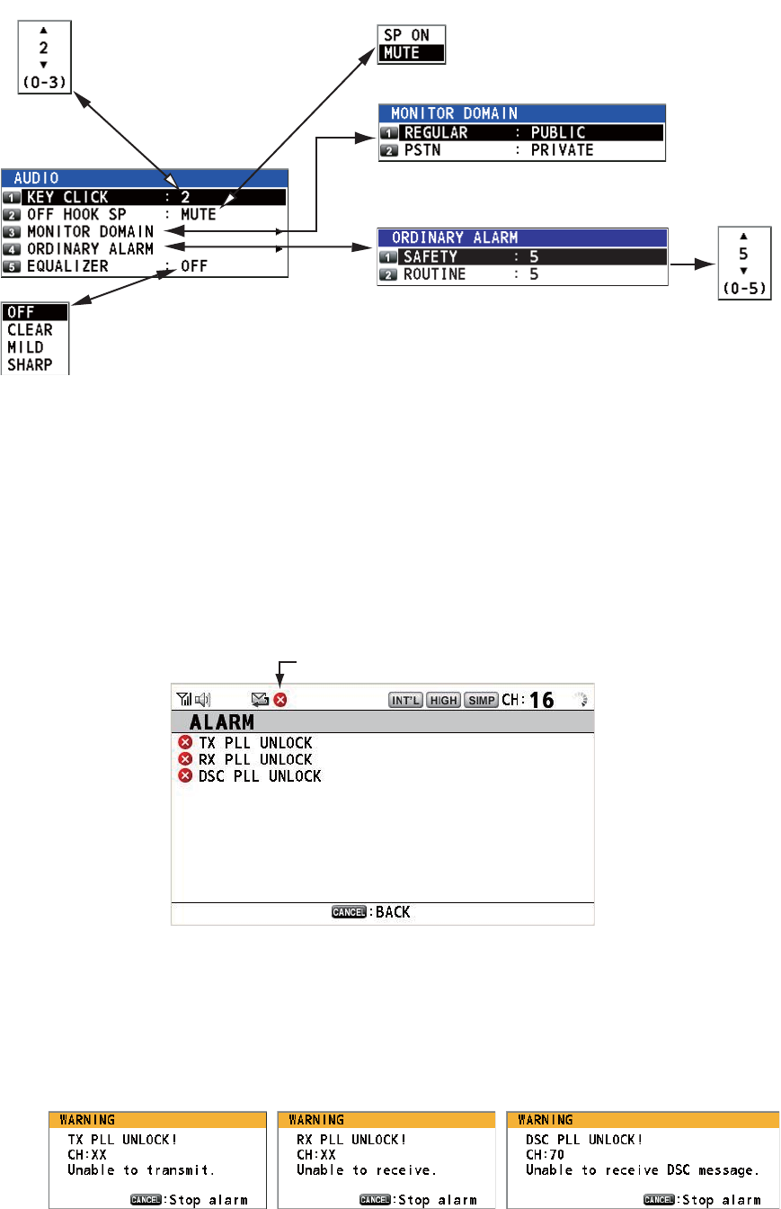
5.20 Alarm Lists
The [ALARM] menu shows all currently violated alarms. When an error occurs, a pop-
up message and a flashing error icon appear on the screen. Press the CANCEL key
to close the pop-up message and stop the flashing of the error icon. When the error is
removed, the error icon disappears.
Rotate the CHANNEL/ENTER knob to select [ALARM] on the [MENU] screen then
push the knob. The following screen appears.
There are three kinds of errors: [TX PLL UNLOCK], [RX PLL UNLOCK], [DSC PLL
UNLOCK].
Errors are displayed in the order shown above, not in the order of occurrence. An error
is deleted from the list when the cause for the error is removed.
These alarms are listed when the following messages appear.
Default: [2]
Turn beep on (setting: [1] - [3])
or off (setting: [0]) when a key
is pressed.
Default: [MUTE]
Turn the speaker on or off
when the handset is off hook.
Rotate the CHANNEL/ENTER knob to set volume
then push the knob.
Default: [OFF]
Adjust tone quality for speaker.
Turn the speakers except in-use one on or off.
[PUBLIC]: On, [PRIVATE]: Off
Error icon
5. MENU OPERATION
5-22
This page is intentionally left blank.
6-1
6. REMOTE HANDSET
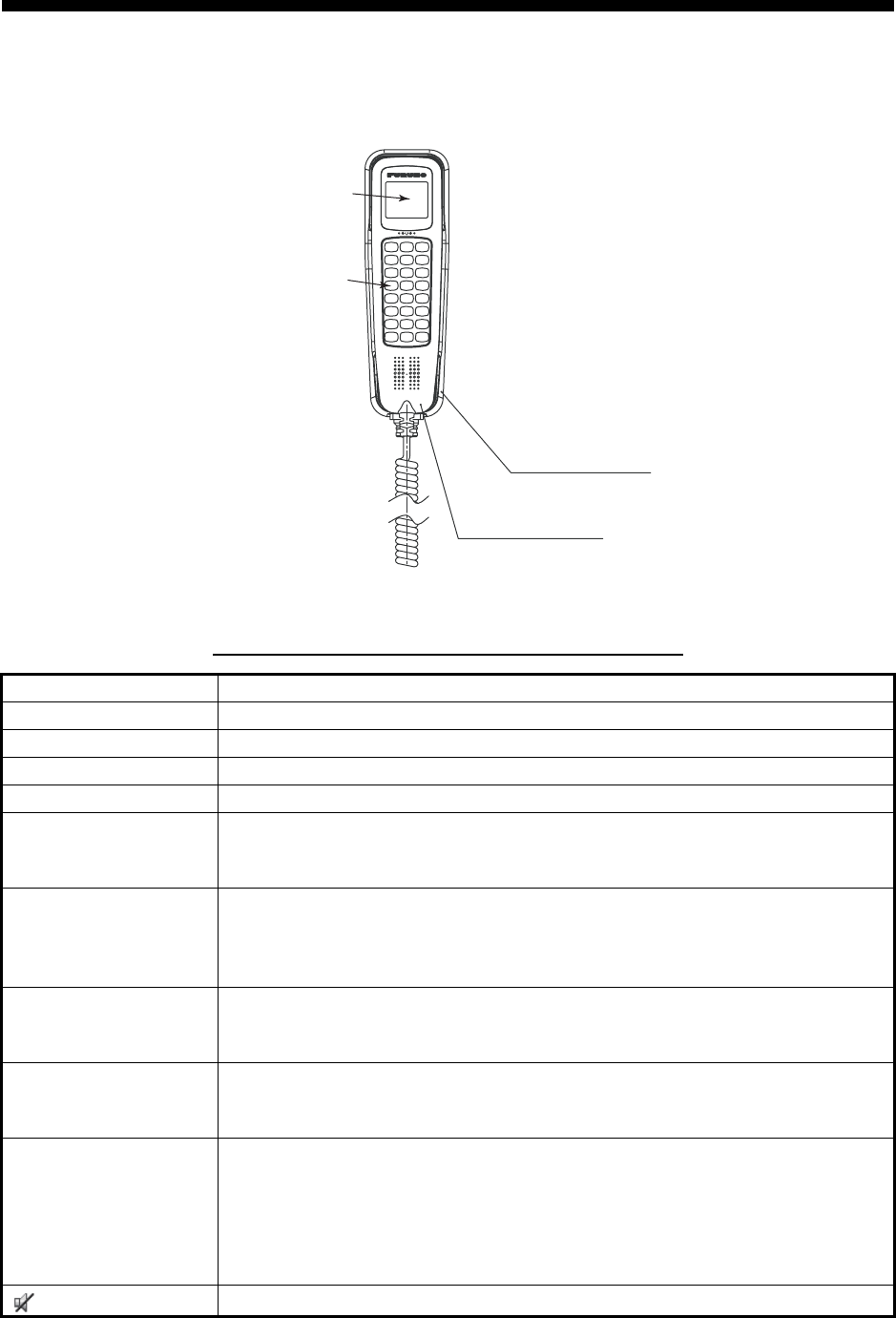
6.1 Controls
Remote station RB-8900(-W) (option)
Description of controls for remote station (handset)
Control Function
DW key Turns the DW function on or off (see section 1.9).
HI/LO key Changes the output power to high (25 W) or low (1 W).
CH16 key Switches to the RT (radiotelephone) screen and sets CH16.
SCAN key Turns the scan function on or off (see section 1.10).
S, T keys • Selects the menu items.
• Selects the channel on the RT screen.
• Adjusts the setting values.
SQ key Adjusts the squelch. Press the SQ key on the RT/OCCUPIED screen then
press the S or T key within three seconds to adjust the squelch (setting
range: AUTO, 0 to 10). To get auto squelch adjustment, press the T key
with the setting 0 (indication: SQA).
VOL key Adjusts the volume. Press the VOL key on the RT/OCCUPIED screen then
press the S or T key within three seconds to adjust the volume (setting
range: 0 to 10).
ENTER key • Moves down one layer when you save the menu option in a layer other
than the lowest one. In the undermost layer, opens the setting window.
• Confirms a selection.
CANCEL key • Silences the audio alarm.
• Returns one layer in a multi-layer menu. In the top layer, closes the menu
then displays the RT screen.
• Cancels the setting in the setting window then goes back one layer in the
menu.
• Cancels the intercom call.
key Turns the loudspeaker on or off.
HS-8900(-W)
Remote handset
LCD
Keyboard
HG-8900(-W)
Handset hanger
6. REMOTE HANDSET
6-2
6.2 How to Turn On/Off the Power
A handset does not have a power key. Turn on or off the power from the transceiver
unit.
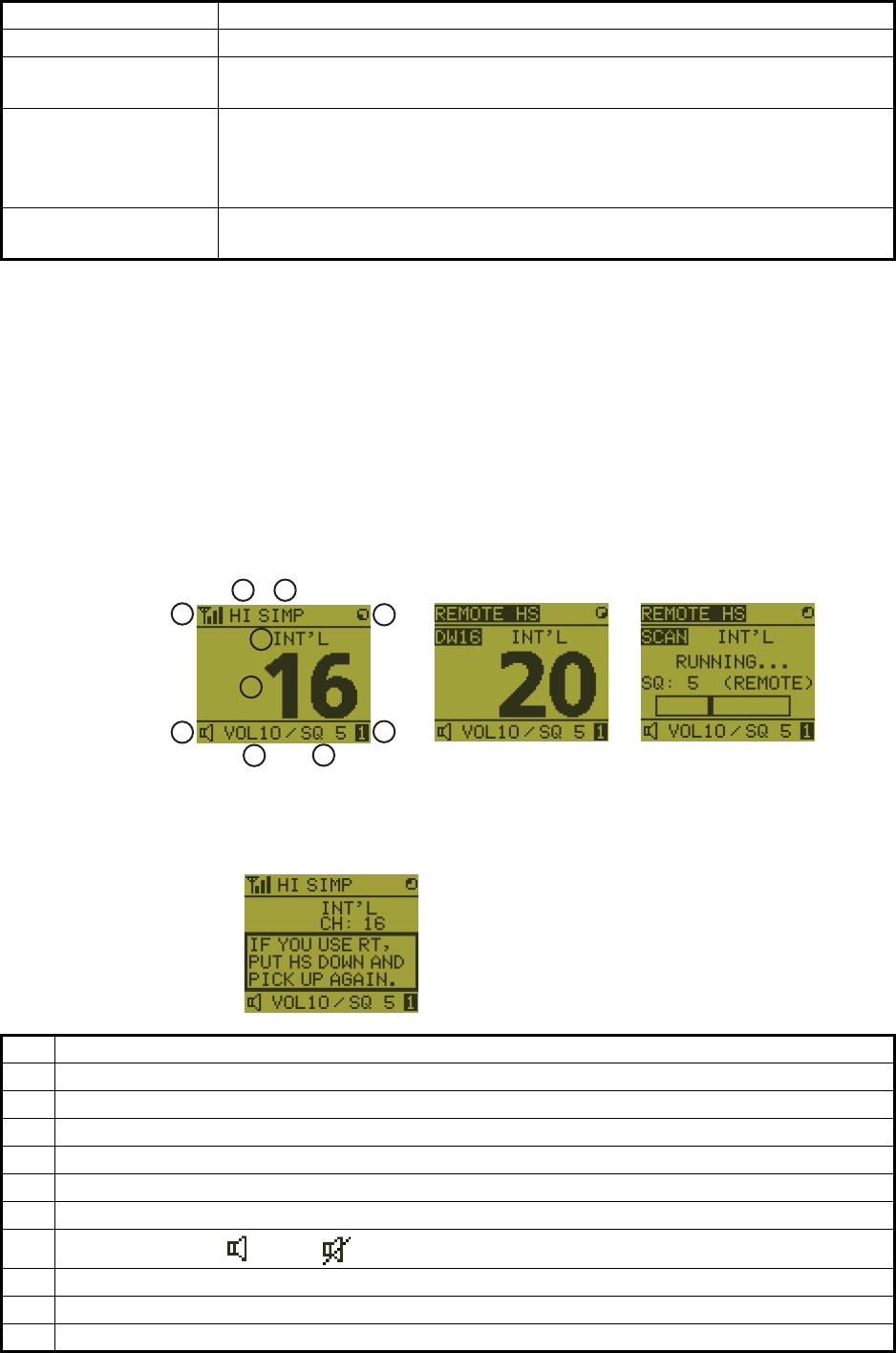
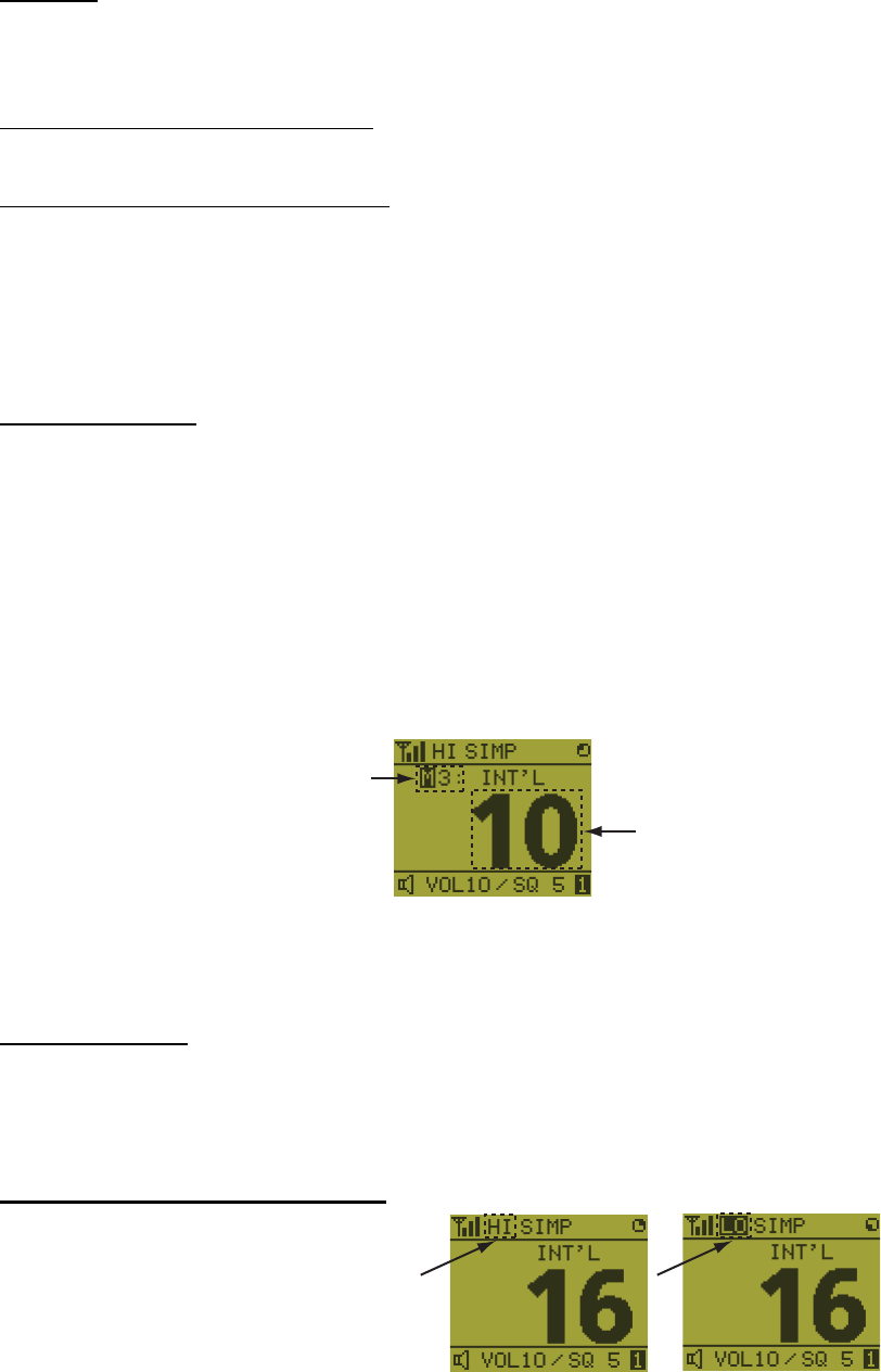
6.3 Radiotelephone (RT) Screen
Below are the radiotelephone (RT) screens on the remote handset.
MENU key Opens/closes the menu.
0 to 9 keys • Enters the channel on the RT screen.
• Selects the menu items.
CONTRAST key Short press: Opens the contrast setup screen. Press the S or T key to
adjust the contrast.
Long press (more than three seconds): Restores the contrast to the de-
fault setting.
BRILL key Opens the brill setup screen. Press the S or T key to adjust the brill. You
can also use the BRILL key.
No. Meaning
1 RX signal strength (This icon does not appear while transmitting.)
2 Output power ([HI]: High, [LO]: Low)
3 Channel type ([SIMP]: Simplex, [DUP]: Duplex)
4 Spinner rotates when the equipment is functioning normally.
5 Channel region ([INT’L], [USA], [CANADA], [INLAND-W], [PRIVATE])
6 Channel
7Loudspeaker on ( ) or off ( )
8 Volume for loudspeaker (0 to 10)
9 Squelch level (0 to 10, AUTO (Indication is [SQA].))
10 Terminal ID ([L]: Left wing handset, [R]: Right wing handset, [1] to [4]: Remote handset 1 to 4)
Control Function
2
1
3
4
5
9
10
6
7
8DW screen
Common RT screen
Scan screen
When no terminal has operation right and a remote handset is off hook,
the following screen appears.
A remote handset can get the
operation right if you hook on
then hook off.
6. REMOTE HANDSET
6-3
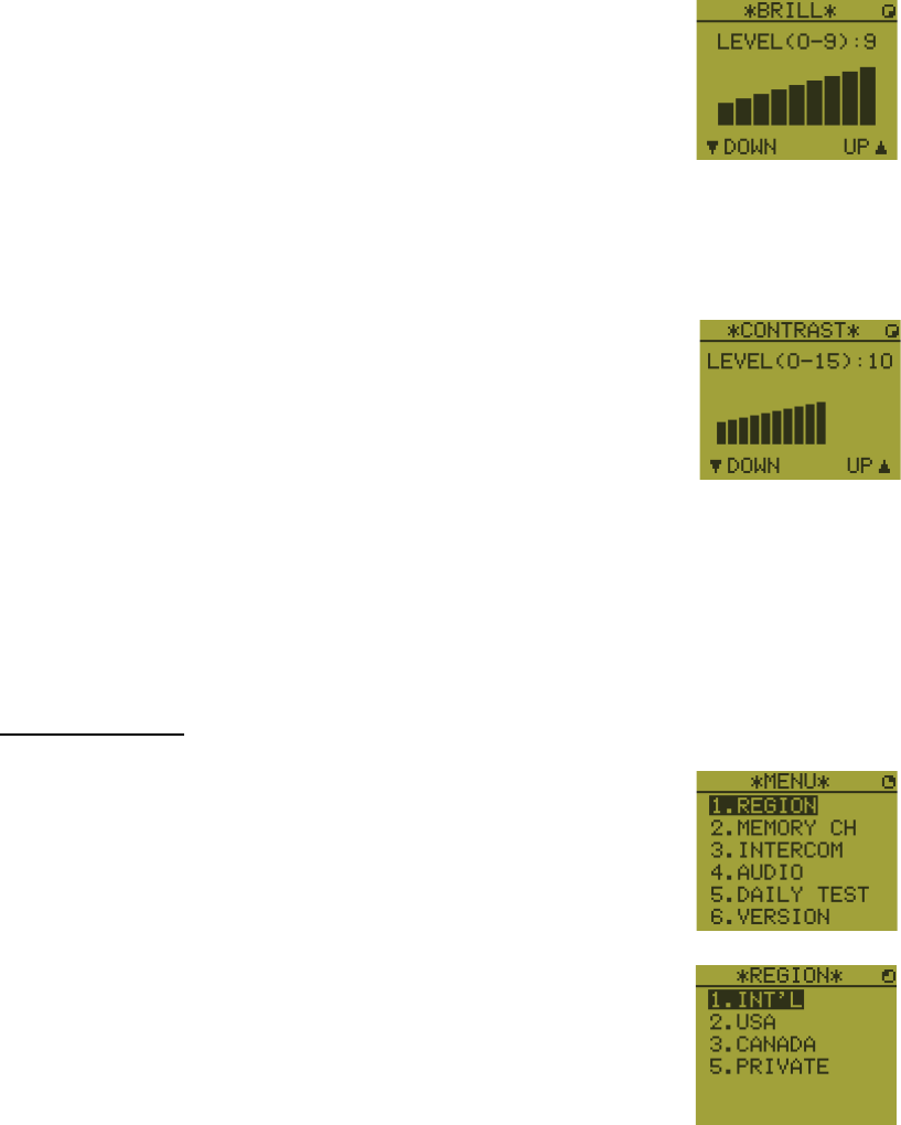
6.4 How to Adjust the Brilliance and Contrast
You can adjust the brilliance of the display and the panel for each remote handset sep-
arately. Also, you can adjust the contrast for each remote handset.
Brilliance
1. Press the BRILL key to show the [BRILL] setting window.
2. Press the S or T key to adjust the brilliance.
3. Press the ENTER key to save the settings and close the
window. To cancel the settings, press the CANCEL key in-
stead of the ENTER key to close the window.
Note: The [BRILL] setting window automatically closes when there is no menu oper-
ation for three seconds.
Contrast
1. Press the CONTRAST key to show the [CONTRAST] set-
ting window.
2. Press the S or T key to adjust the contrast.
3. Press the ENTER key to save the settings and close the
window. To cancel the settings, press the CANCEL key in-
stead of the ENTER key to close the window.
Note: The [CONTRAST] setting window automatically closes when there is no menu
operation for three seconds.
6.5 How to Select the Channel Region, Channel
Channel region
1. Press the MENU key to open the [MENU] screen.
2. Press the S or T key to select [REGION] then press the
ENTER key.
3. Press the S or T key to select the channel mode desired then press the ENTER
key. The following modes are available.
• [INT’L]: International mode
• [USA]: USA mode
• [CANADA]: CANADA mode
• [INLAND-W]: Inland waterway mode
• [PRIVATE]: Private channel
6. REMOTE HANDSET
6-4
Note 1: Only permitted channel regions are displayed, which are set by the install-
er of the equipment.
Note 2: Private channels are available only where permitted by the authorities.
The [USA], [CANADA], [INLAND-W], [PRIVATE] can also be set by a qualified
service technician.
Channel
The channel can be set manually on the RT screen. Enter the channel by one of the
methods below.
Enter channel with the S or T key:
Press the S or T key on the RT screen.
Enter channel with the numeric keys:
Use the numeric keys to enter channel on the RT screen. (It is not necessary to press
the ENTER key after entering the channel; the setting is confirmed one second after
it is entered.)
Note: When the transceiver unit is in on hook condition, you can change the channel
with the remote handset.
Memory channel
You can easily call up a channel which you registered in the transceiver unit as a mem-
ory channel (see section 5.4).
1. Press the MENU key to open the [MENU] screen.
2. Press the S or T key to select [MEMORY CH] then press the ENTER key.
3. Press the S or T key to select [ON] or [OFF] then press the ENTER key.
When you select [ON], "M" appears on the screen. On the RT screen, you can se-
lect a memory channel by pressing the S or T key. The following figure shows
the example for CH 10.
6.6 Transmission
How to transmit
Press the PTT (Push-to-talk) switch on the handset to talk, and release it to listen for
a response. "TX" appears at the top left-hand corner of the screen during transmis-
sion.
How to change the output power
Press the HI/LO key to change the
output power to high and low alter-
nately. "HI" or "LO" appears on the
screen depending on your selection.
Channel number
“3” means that you turned 3
channels of the selected
channel region to [ON] in
the [MEMORY CONFIG]
menu in the transceiver unit.
6. REMOTE HANDSET
6-5
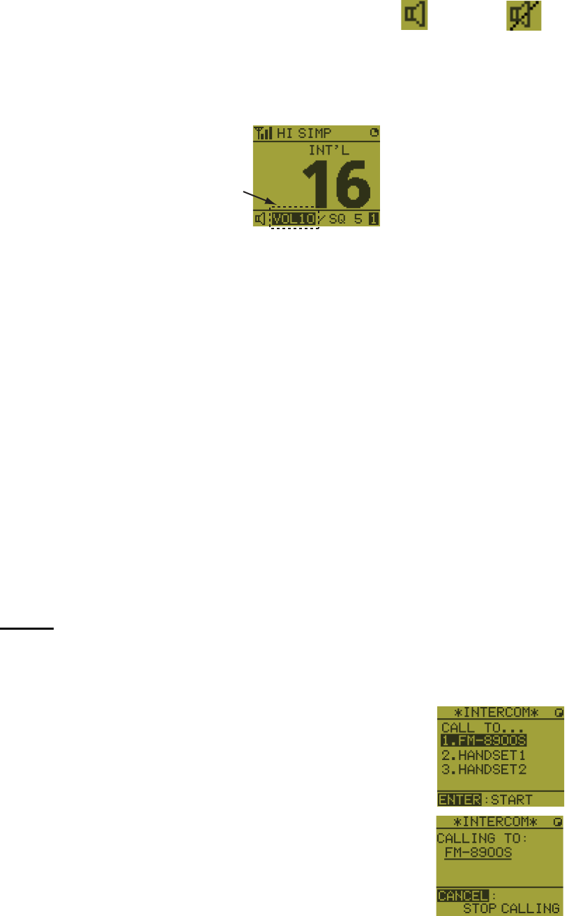
6.7 How to Turn On/Off the Loudspeaker
You can turn the loudspeaker (other than DSC communication, error, and key beep)
on or off.
1. Press the SPK key to alternately disable or en-
able the loudspeaker.
2. To adjust the volume of the loudspeaker, press the VOL key. The screen changes
as below.
3. Press the S or T key to adjust the volume within three seconds. The time for re-
verse highlighting is three seconds.
6.8 Quick Selection of CH16
Press the CH16 key to select CH16. The CH16 (156.8 MHz) is the international fre-
quency for distress traffic and for calling by radiotelephone. The CH16 can also be
used by ship stations for call and reply. To facilitate the reception of distress calls and
distress traffic, all transmissions on CH16 should be kept to a minimum and should not
exceed one minute. Before transmitting on the CH16, a station should listen on this
frequency for a reasonable period to make sure that no distress traffic is being sent.
6.9 Intercom
The built-in intercom permits voice communications between two control units. The
combination of two controls is transceiver unit & remote handset, or remote handset
& remote handset.
Calling
You can call over the intercom only in off hook condition.
1. Press the MENU key to open the [MENU] screen.
2. Press the S or T key to select [INTERCOM] then press
the ENTER key.
3. Press the S or T key to select the called party’s control
unit then press the ENTER key.
The called party’s control unit and yours ring.
To cancel calling, press the CANCEL key.
Speaker ON Speaker OFF
Reverse highlighting
6. REMOTE HANDSET
6-6
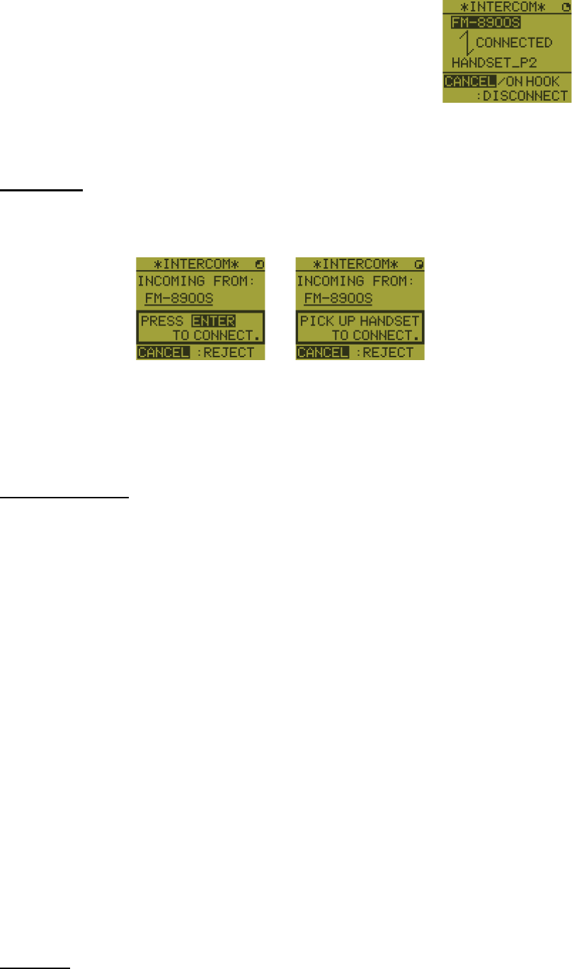
4. When the called party picks up their handset, the screen
as shown in the right figure appears. Start communica-
tions.
Note: You do not have to press the PTT switch to commu-
nicate.
5. Hang up the handset or press the CANCEL or the CH16 key to turn the intercom
off. The RT screen appears.
Answering
1. The control unit rings and the following screen appears. To cancel reply, press the
CANCEL key.
2. Press the ENTER key with off hook condition or pick up the handset with on hook
condition to start communications.
3. Hang up the handset or press the CANCEL key to turn the intercom off. The RT
screen appears.
Earpiece volume
You can adjust the volume of the earpiece during intercom communication by pressing
the S or T key. After intercom communication, the earpiece volume is reverted to the
setting value you set on [EARPIECE LEVEL] (see section 6.11).
Note: Neither key click nor key error sounds during intercom communication.
6.10 How to Change the Terminal ID
1. Turn off the remote handset by the transceiver unit.
2. While you hold the MENU key, turn on the remote handset by the transceiver unit.
The setting window for terminal ID appears.
3. Enter the terminal ID, using the 1 to 6 keys, then press the ENTER key. Do not
assign the same number to multiple remote stations.
Note: Restart the remote handset by the transceiver unit after changing terminal ID.
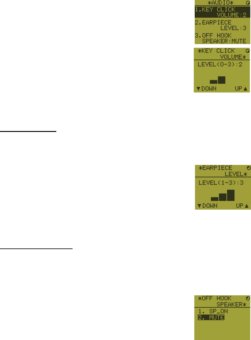
6.11 Audio setting
The [AUDIO] menu enables or disables key beep and adjusts the volume of the ear-
piece and off hook loudspeaker.
Key click
1. Press the MENU key to open the [MENU] screen.
Off hook condition On hook condition
6. REMOTE HANDSET
6-7
2. Press the S or T key to select [AUDIO] then press the EN-
TER key.
3. Press the S or T key to select [KEY CLICK VOLUME] then
press the ENTER key.
4. Press the S or T key to set the key click level (setting range: 0 (OFF), 1, 2 or 3).
5. Press the ENTER key. To cancel the setting, press the CANCEL key.
Earpiece volume
1. Press the MENU key to open the [MENU] screen.
2. Press the S or T key to select [AUDIO] then press the ENTER key.
3. Press the S or T key to select [EARPIECE LEVEL] then
press the ENTER key.
Note: Neither key click nor key error sounds during the
[EARPIECE LEVEL] display.
4. Press the S or T key to set the earpiece volume level (setting range: 1 to 3).
5. Press the ENTER key. To cancel the setting, press the CANCEL key.
Off hook loudspeaker
You can set the loudspeaker on or off according to off hook condition.
1. Press the MENU key to open the [MENU] screen.
2. Press the S or T key to select [AUDIO] then press the ENTER key.
3. Press the S or T key to select [OFF HOOK SPEAKER]
then press the ENTER key.
4. Press the S or T key to select [SP_ON] or [MUTE].
[SP_ON]: Loudspeaker is activated when off hook.
[MUTE]: Loudspeaker is deactivated when off hook.
5. Press the ENTER key. To cancel the setting, press the CANCEL key.
6. REMOTE HANDSET
6-8
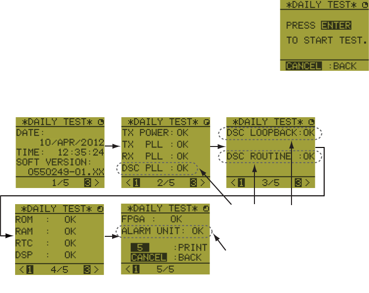
6.12 How to Test FM-8900S from a Remote Handset
1. Press the MENU key to open the [MENU] screen.
2. Press the S or T key to select [DAILY TEST] then press
the ENTER key.
3. Press the ENTER key to start the test. You can confirm the test results for FM-
8900S with the 1 or 3 key.
6.13 How to Display the Program Versions
1. Press the MENU key to open the [MENU] screen.
2. Press the S or T key to select [VERSION] then press the ENTER key. The pro-
gram versions for FM-8900S and HS-8900 appear.
6.14 Squelch
• The squelch value is common to all remote handsets. If you change a squelch value
for a remote handset, squelch values for all other remote handsets are changed ac-
cordingly.
• You can not change a squelch value for a remote handset while the squelch is being
adjusted by another remote handset.
• When the DW or scan is active, the squelch value from the terminal (transceiver unit
or remote handset) that initiated the DW or scan is used.
This item is not displayed when
there is no alarm unit.
Press the 3 key for the next page and the 1 key for the previous page.
These items are displayed
only when entering own
ship’s MMSI.
7-1
7. MAINTENANCE &
TROUBLESHOOTING
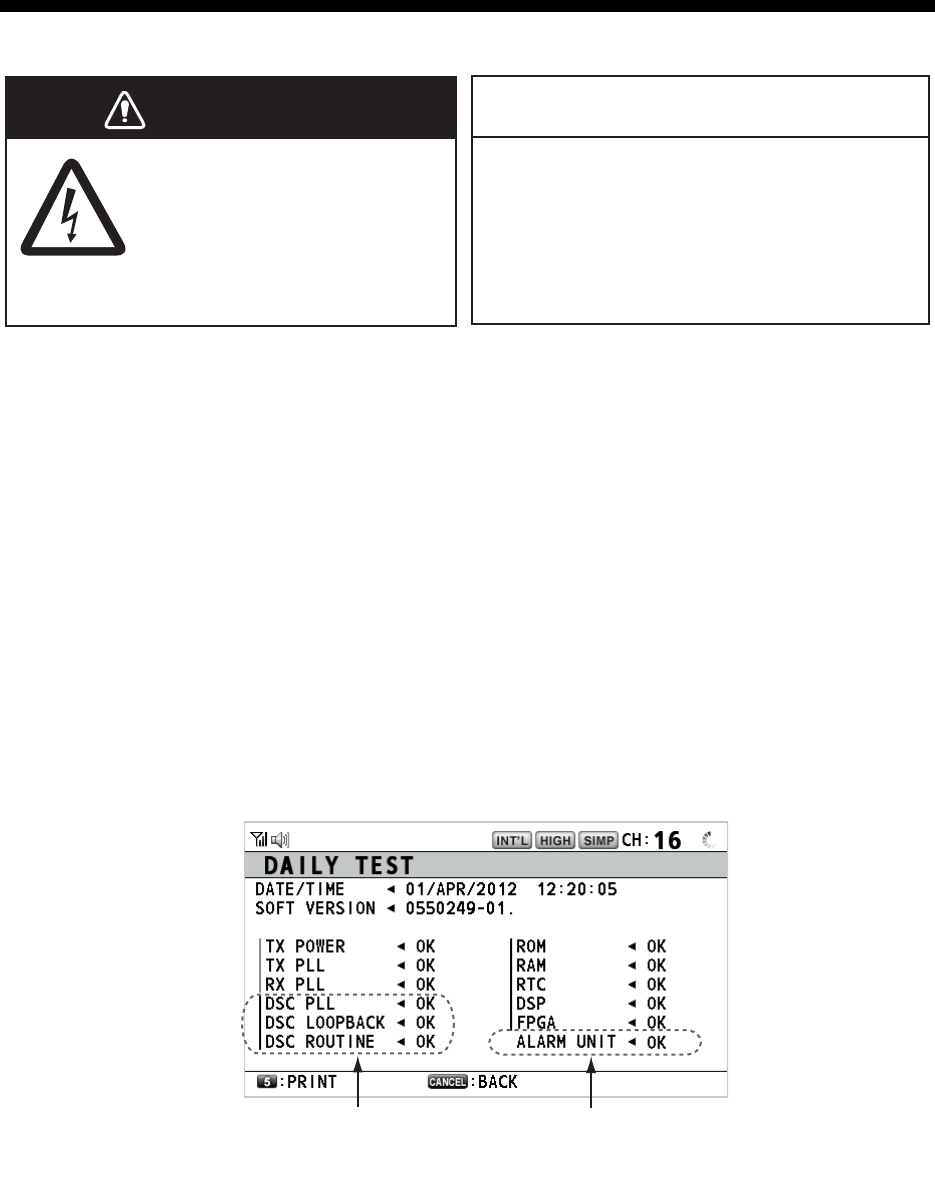
7.1 Daily Test
Do the daily test to check the radiotelephone for proper operation.
Rotate the CHANNEL/ENTER knob to select [TEST] on the [MENU] screen then push
the knob. The daily test starts. After the test is completed, the audio alarm sounds and
the screen shown below appears. This screen shows:
• Test date
• Program version number
• Test results for TX power, TX PLL, RX PLL, DSC PLL, DSC loopback, DSC routine,
ROM, RAM, RTC, DSP, FPGA and alarm unit (only when connecting the alarm
unit), shown as [OK] or [NG] (No Good). For NG, contact your dealer for advice. The
DSC test checks, using a DSC signal, the encode and decode functions of the sig-
nal processor.
To print out the test result manually, press the 5 key. Automatic printing of the daily
test is available. See section 5.5.
Do not apply paint, anti-corrosive sealant
or contact spray to plastic parts or
equipment coating.
Those items contain products that can
damage plastic parts and equipment coating.
ELECTRICAL SHOCK HAZARD
Do not open the equipment.
Only qualified personnel
should work inside the
equipment.
WARNING
WARNING
NOTICE
x
x
This item is not available
when not connecting the
alarm unit.
These items are not
available when not enter-
ing own ship’s MMSI.

7. MAINTENANCE & TROUBLESHOOTING
7-2
7.2 Maintenance
Regular maintenance helps to keep your equipment in good condition and prevents
future problems. Check the items shown in the table below.
7.3 Simple Troubleshooting
The table below provides possible problems and the means with which to restore nor-
mal operation. If normal operation cannot be restored, do not attempt to check inside
the equipment. Any servicing should be referred to a qualified technician.
Item Check point Remedy/Remarks
Antenna Check for physical damage and corrosion. Replace damaged parts.
Wire
antenna
Check that the antenna is properly spanned
and separated sufficiently from metallic
structures.
If necessary, re-span antenna.
Insulators
for antenna
Check for salt water deposits on insulators.
Check that connection at the lead-in insula-
tor is tight and rust-free.
Replace damaged insulator(s). Remove
salt water deposits. Clean with fresh
water, then dry. Remove rust, then
tighten bolts and lock nuts. Cover me-
tallic surface with sealing compound.
Transceiver
unit
• Check ground connection.
• Check connection at signal cable, coaxial
cable, control cable, power cable and ex-
ternal equipment (including navigator).
• Confirm that there are no objects on the
top of the transceiver unit.
• Remove dust from transceiver unit with
soft cloth.
Note: Do not use chemical cleaners to
clean the transceiver unit; they can remove
paint or markings and deform the equip-
ment.
• Tighten the loosened connections;
remove foreign materials from con-
nectors.
• Remove any objects.
• Wipe the LCD carefully to prevent
scratching, using tissue paper and an
LCD cleaner. To remove dirt or salt
deposits, use an LCD cleaner, wiping
slowly with tissue paper so as to dis-
solve the dirt or salt. Change paper
frequently so the salt or dirt does not
scratch the LCD.
Power
supply
Check that the supply voltage at transmis-
sion is within the rated range (21.6 to 31.2
VDC at the power connector).
If not within the range, check power
source. Low voltage may cause erratic
operation.
Power fuse Check if a power fuse (7A) has blown. If the fuse has blown, find out the cause
before replacing it (Type: FGBO 125V
7A PBF). If it blows after replacement,
contact your dealer.
Problem Probable cause Remedy
Power cannot be
turned on.
• Mains switchboard is off.
• (DC) voltage is too high or too low.
• Battery has discharged, or poor
contact at terminals.
• Turn on the mains switchboard.
• Check supply voltage.
• Recharge the battery and tighten
the battery terminals.
Display indications
do not appear.
Display brilliance is too low. Press the BRILL key to adjust the
display brilliance.
Power is on but no
sound from the main
speaker.
Main speaker is off. Press the key to turn on the main
speaker.
Output power re-
duced to LOW
Power is automatically reduced to pro-
tect against overheating due to contin-
uous transmission.
Wait until the unit cools.
7. MAINTENANCE & TROUBLESHOOTING
7-3
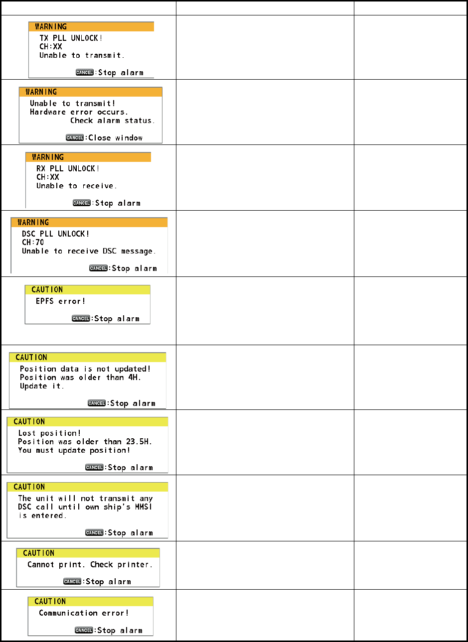
7.4 Warning and Caution Messages
The table below shows error messages, their meanings, and remedies. To delete the
messages, press the CANCEL key.
Message Meaning Remedy
TX PLL unlock. Transmission is dis-
abled.
Contact your dealer.
TX PLL unlock error. Transmission is
disabled.
Contact your dealer.
RX PLL unlock. Reception is dis-
abled.
Contact your dealer.
DSC (CH70) PLL unlock. Contact your dealer.
Position data is not input for ten min-
utes.
Note: This message does not ap-
pear when [INPUT TYPE] in the [PO-
SITION] menu is set to [MANUAL].
Enter the position.
Position data has not been updated
for 4H.
Enter the position.
Position data has not been updated
for 23.5H.
Enter the position.
You tried to send a DSC message
but your MMSI has not been regis-
tered in the equipment.
Enter MMSI no. of
your ship.
Printer trouble. Cannot print. Check the printer
(connection, power,
paper).
Communication between the trans-
ceiver unit and a remote handset is
lost for three seconds.
Check the connection
with the remote hand-
set. If unsolved, con-
tact your dealer.
7. MAINTENANCE & TROUBLESHOOTING
7-4
7.5 Test Call
This function sends a test signal to a coast or ship station. For that reason, it should
not be executed unnecessarily. You can prepare a test call beforehand (see
paragraph 5.14.5).
1. Press the OTHER DSC MSG key to open the [COMPOSE MESSAGE].
2. Rotate the CHANNEL/ENTER knob to select [MSG TYPE] then push the knob.
3. Rotate the CHANNEL/ENTER knob to select [TEST MSG] then push the knob.
[PRIORITY] is automatically set to [SAFETY].
4. With [TO] selected, push the CHANNEL/ENTER knob.
5. Rotate the CHANNEL/ENTER knob to select [DIRECT INPUT], [ADDRESS
BOOK DATA] or [AIS TARGET DATA] then push the knob.
[DIRECT INPUT]: Enter the MMSI of the station where to send the call then push
the CHANNEL/ENTER knob.
[ADDRESS BOOK DATA]: Select an MMSI from the [ADDRESS BOOK] (see
section 5.13) then push the CHANNEL/ENTER knob.
[AIS TARGET DATA]: Select an MMSI from the [AIS TARGET LIST] then push
the CHANNEL/ENTER knob.
6. With [GO TO CALL] selected, push the CHANNEL/ENTER knob to send the test
message. The screen is changed to the one for transmission. After the call is sent,
the equipment waits for acknowledgement of the call. The timer starts counting up
the time to wait for acknowledgement.
7. Do one of the following.
Test acknowledge message received
The audio alarm sounds and the message "TEST ACK received! [CANCEL]: Stop
alarm" appears. Press the CANCEL key to silence the alarm.
No response
Re-send call: Rotate the CHANNEL/ENTER knob to select [RESEND] in the user op-
tions area then push the knob.
Cancel call: Rotate the CHANNEL/ENTER
knob to select [QUIT] in the user options
area then push the knob. The message
shown in the right figure appears.
Rotate the CHANNEL/ENTER knob to se-
lect [Yes] then push the knob.
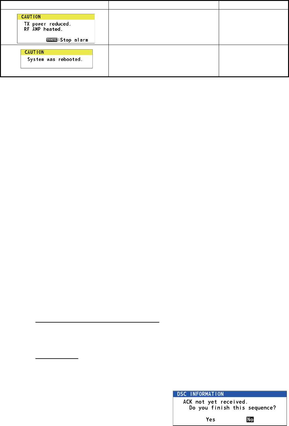
RF amplifier is too hot. Transmission
power is reduced.
Allow the transceiver
unit to cool. If the mes-
sage appears again,
contact your dealer.
Internal error. System is rebooted. System automatically
restarts. If the problem
occurs again, contact
your dealer.
Message Meaning Remedy
AP-1
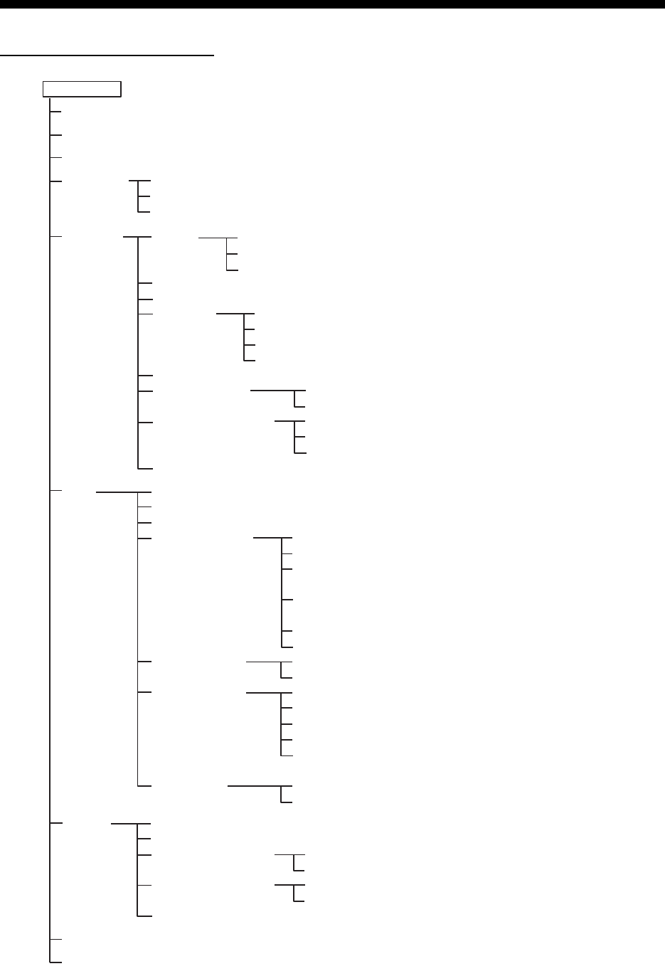
APPENDIX 1 MENU TREE
Transceiver unit FM-8900S
MENU key Bold: Default setting
HS VOL (1 - 20, 15)
TEST
INTERCOM
CH MODE
SYSTEM
DSC
AUDIO
ALARM (Open alarm list)
SERVICE (For service technician)
PRINT
POSITION (Open setting window)
DATE/TIME (Open setting window)
TIMEOUT
INTERCOM NAME (Open intercom name editting screen)
AUTO REVERT
EXTERNAL ALARM
RT APPLICATION (GUIDE, HS STATE, SQ METER)
INDIVIDUAL (MANUAL, AUTO (UNABLE))
PSTN (AUTO (ABLE), AUTO (UNABLE))
REASON (NO REASON, BUSY, EQUIP ERROR,
CAN'T USE MODE, CAN'T USE CH)
POSITION MSG (AUTO (ABLE),
AUTO (UNABLE), MANUAL)
POLLING MSG (AUTO, MANUAL)
TEST MSG (AUTO, MANUAL)
ADDRESS BOOK (Open address data list)
MSG FILE (Open message file list)
LOG (Open log data list)
ACK SETTINGS
SPECIAL MSG
PROPOSE CH
MMSI X10*
TX MSG (AUTO, MANUAL)
RX MSG (AUTO, MANUAL)
DAILY TEST (AUTO, MANUAL)
MENU END (10MIN, NO TIMEOUT)
DSC GENERAL (15MIN, NO TIMEOUT)
RX DISTRESS (15MIN, NO TIMEOUT)
TELEPHONE (10SEC, 30SEC, 10MIN)
URGENCY (ON, OFF)
SAFETY (ON, OFF)
ROUTINE (ON, OFF)
NEUTRAL (ABLE, UNABLE)
MEDICAL (ABLE, UNABLE)
INT’L (01 - 88)
USA (01 - 88)
CANADA (01 - 88)
INLAND-W* (01 - 88)
PRIVATE (CH16 and a max. of 19 other channels
selected in the [SERVICE] menu.)
X10 (0 - 9; 0)
MODE (ZERO, NON-ZERO, REJECT)
KEY CLICK (0 - 3; 2)
OFF HOOK SP (SP ON, MUTE)
MONITOR DOMAIN
ORDINARY ALARM
EQUALIZER (OFF, CLEAR, MILD, SHARP)
REGULAR (PUBLIC, PRIVATE)
PSTN (PUBLIC, PRIVATE)
SAFETY (0 - 5; 5)
ROUTINE (0 - 5; 5)
REGION (INT’L, USA, CANADA, INLAND-W*, PRIVATE)
MEMORY (ON, OFF)
MEMORY CONFIG (Open memory config window)
MAIN (RT+DSC, RT, OFF)
REMOTE (ON, OFF)
*: These menu items appear
according to the settings
of the [SERVICE] menu.

APPENDIX 1 MENU TREE
AP-2
Remote handset HS-8900(-W)
MENU key Bold: Default setting
REGION (INT’L, USA, CANADA, INLAND-W*, PRIVATE)
MEMORY CH (ON, OFF)
INTERCOM
AUDIO
DAILY TEST (Display the test results for FM-8900S)
VERSION (Display the program versions for FM-8900S and HS-8900)
KEY CLICK VOLUME (0 (OFF) - 3, 2)
EARPIECE LEVEL (1 - 3, 3)
OFF HOOK SPEAKER (SP_ON, MUTE)
*: This menu item appears according to the setting
of the [SERVICE] menu in the FM-8900S.

AP-3
APPENDIX 2 MARINE VHF CHANNEL
LISTS
International channels
CH TX (MHz) RX (MHz) Remark CH TX (MHz) RX (MHz) Remark
01 156.050 160.650 60 156.025 160.625
02 156.100 160.700 61 156.075 160.675
03 156.150 160.750 62 156.125 160.725
04 156.200 160.800 63 156.175 160.775
05 156.250 160.850 64 156.225 160.825
06 156.300 156.300 65 156.275 160.875
07 156.350 160.950 66 156.325 160.925
08 156.400 156.400 67 156.375 156.375
09 156.450 156.450 68 156.425 156.425
10 156.500 156.500 69 156.475 156.475
11 156.550 156.550 70 156.525 156.525 DSC
12 156.600 156.600 71 156.575 156.575
13 156.650 156.650 72 156.625 156.625
14 156.700 156.700 73 156.675 156.675
15 156.750 156.750 74 156.725 156.725
16 156.800 156.800 75 156.775 156.775 Low PWR
17 156.850 156.850 76 156.825 156.825 Low PWR
18 156.900 161.500 77 156.875 156.875
19 156.950 161.550 78 156.925 161.525
20 157.000 161.600 79 156.975 161.575
21 157.050 161.650 80 157.025 161.625
22 157.100 161.700 81 157.075 161.675
23 157.150 161.750 82 157.125 161.725
24 157.200 161.800 83 157.175 161.775
25 157.250 161.850 84 157.225 161.825
26 157.300 161.900 85 157.275 161.875
27 157.350 161.950 86 157.325 161.925
28 157.400 162.000 87 157.375 157.375
88 157.425 157.425

APPENDIX 2 MARINE VHF CHANNEL LISTS
AP-4
USA channels
*: USCG (United States Coast Guard) only (General use prohibited)
USA weather channels
CH TX (MHz) RX (MHz) Remark CH TX (MHz) RX (MHz) Remark
01 156.050 156.050 60 - -
02 - - 61 - -
03 - - 62 - -
04 - - 63 156.175 156.175
05 156.250 156.250 64 - -
06 156.300 156.300 65 156.275 156.275
07 156.350 156.350 66 156.325 156.325
08 156.400 156.400 67 156.375 156.375 Low PWR
09 156.450 156.450 68 156.425 156.425
10 156.500 156.500 69 156.475 156.475
11 156.550 156.550 70 156.525 156.525 DSC
12 156.600 156.600 71 156.575 156.575 Low PWR
13 156.650 156.650 Low PWR 72 156.625 156.625
14 156.700 156.700 73 156.675 156.675
15 - 156.750 74 156.725 156.725
16 156.800 156.800 75 156.775 156.775 Low PWR
17 156.850 156.850 76 156.825 156.825 Low PWR
18 156.900 156.900 77 156.875 156.875 Low PWR
19 156.950 156.950 78 156.925 156.925
20 157.000 157.000 79 156.975 156.975
21 157.050 157.050 * 80 157.025 157.025
22 157.100 157.100 81 157.075 157.075 *
23 157.150 157.150 * 82 157.125 157.125 *
24 157.200 161.800 83 157.175 157.175 *
25 157.250 161.850 84 157.225 161.825
26 157.300 161.900 85 157.275 161.875
27 157.350 161.950 86 157.325 161.925
28 157.400 162.000 87 157.375 157.375
88 157.425 157.425
WX RX (MHz) WX RX (MHz)
01 162.550 06 162.500
02 162.400 07 162.525
03 162.475 08 161.650
04 162.425 09 161.775
05 162.450 10 163.275

APPENDIX 2 MARINE VHF CHANNEL LISTS
AP-5
Canadian channels
*: DFO/Canadian Coast Guard only
**: For communications between the Coast Guard and non-Coast Guard stations only
Canadian weather channels
CH TX (MHz) RX (MHz) Remark CH TX (MHz) RX (MHz) Remark
01 156.050 160.650 60 156.025 160.625
02 156.100 160.700 61 156.075 156.075
03 156.150 160.750 62 156.125 156.125
04 156.200 156.200 63 156.175 156.175
05 156.250 156.250 64 156.225 160.825
06 156.300 156.300 65 156.275 156.275
07 156.350 156.350 66 156.325 156.325
08 156.400 156.400 67 156.375 156.375
09 156.450 156.450 68 156.425 156.425
10 156.500 156.500 69 156.475 156.475
11 156.550 156.550 70 156.525 156.525 DSC
12 156.600 156.600 71 156.575 156.575
13 156.650 156.650 72 156.625 156.625
14 156.700 156.700 73 156.675 156.675
15 156.750 156.750 Low PWR 74 156.725 156.725
16 156.800 156.800 75 156.775 156.775 Low PWR
17 156.850 156.850 Low PWR 76 156.825 156.825 Low PWR
18 156.900 156.900 77 156.875 156.875
19 156.950 156.950 78 156.925 156.925
20 157.000 161.600 Low PWR 79 156.975 156.975
21 157.050 157.050 * 80 157.025 157.025
22 157.100 157.100 ** 81 157.075 157.075 *
23 157.150 161.750 82 157.125 157.125 *
24 157.200 161.800 83 157.175 157.175 *
25 157.250 161.850 84 157.225 161.825
26 157.300 161.900 85 157.275 161.875
27 157.350 161.950 86 157.325 161.925
28 157.400 162.000 87 157.375 157.375
88 157.425 157.425
WX RX (MHz) WX RX (MHz)
01 162.550 06 162.500
02 162.400 07 162.525
03 162.475 08 161.650
04 162.425 09 161.775
05 162.450 10 163.275

APPENDIX 2 MARINE VHF CHANNEL LISTS
AP-6
Inland waterways (INLAND-W) channels
CH TX (MHz) RX (MHz) Remark CH TX (MHz) RX (MHz) Remark
01 156.050 160.650 60 156.025 160.625
02 156.100 160.700 61 156.075 160.675
03 156.150 160.750 62 156.125 160.725
04 156.200 160.800 63 156.175 160.775
05 156.250 160.850 64 156.225 160.825
06 156.300 156.300 Low PWR 65 156.275 160.875
07 156.350 160.950 66 156.325 160.925
08 156.400 156.400 Low PWR 67 156.375 156.375
09 156.450 156.450 68 156.425 156.425
10 156.500 156.500 Low PWR 69 156.475 156.475
11 156.550 156.550 Low PWR 70 156.525 156.525 DSC
12 156.600 156.600 Low PWR 71 156.575 156.575 Low PWR
13 156.650 156.650 Low PWR 72 156.625 156.625 Low PWR
14 156.700 156.700 Low PWR 73 156.675 156.675
15 156.750 156.750 Low PWR 74 156.725 156.725 Low PWR
16 156.800 156.800 75 156.775 156.775 Low PWR
17 156.850 156.850 Low PWR 76 156.825 156.825 Low PWR
18 156.900 161.500 77 156.875 156.875 Low PWR
19 156.950 161.550 78 156.925 161.525
20 157.000 161.600 79 156.975 161.575
21 157.050 161.650 80 157.025 161.625
22 157.100 161.700 81 157.075 161.675
23 157.150 161.750 82 157.125 161.725
24 157.200 161.800 83 157.175 161.775
25 157.250 161.850 84 157.225 161.825
26 157.300 161.900 85 157.275 161.875
27 157.350 161.950 86 157.325 161.925
28 157.400 162.000 87 157.375 157.375
88 157.425 157.425

APPENDIX 2 MARINE VHF CHANNEL LISTS
AP-7
Private channels
- Continued -
TX (MHz) RX (MHz) CH no. (current) Remark
Simplex/Semi-duplex Simplex Semi-duplex
155.000 155.000 159.600 180
155.025 155.025 159.625 181
155.050 155.050 159.650 182
155.075 155.075 159.675 183
155.100 155.100 159.700 184
155.125 155.125 159.725 185
155.150 155.150 159.750 186
155.175 155.175 159.775 187
155.200 155.200 159.800 188
155.225 155.225 159.825 189
155.250 155.250 159.850 190
155.275 155.275 159.875 191
155.300 155.300 159.900 192
155.325 155.325 159.925 193
155.350 155.350 159.950 194
155.375 155.375 159.975 195
155.400 155.400 160.000 196
155.425 155.425 160.025 197
155.450 155.450 160.050 198
155.475 155.475 160.075 199
155.500 155.500 160.100 120(L1)
155.525 155.525 160.125 121(L2)
155.550 155.550 160.150 122
155.575 155.575 160.175 123
155.600 155.600 160.200 124
155.625 155.625 160.225 125(F1)(P1)
155.650 155.650 160.250 126(L3)
155.675 155.675 160.275 127
155.700 155.700 160.300 128
155.725 155.725 160.325 129
155.750 155.750 160.350 130
155.775 155.775 160.375 131(F2)(P2)
155.800 155.800 160.400 132
155.825 155.825 160.425 133(F3)(P3)
155.850 155.850 160.450 134
155.875 155.875 160.475 135
155.900 155.900 160.500 136
155.925 155.925 160.525 137
155.950 155.950 160.550 138
155.975 155.975 160.575 139

APPENDIX 2 MARINE VHF CHANNEL LISTS
AP-8
- Continued -
TX (MHz) RX (MHz) CH no. (current) Remark
Simplex/Semi-duplex Simplex Semi-duplex
156.000 156.000 160.600 00
156.025 156.025 160.625 60
156.050 156.050 160.650 01
156.075 156.075 160.675 61
156.100 156.100 160.700 02
156.125 156.125 160.725 62
156.150 156.150 160.750 03
156.175 156.175 160.775 63
156.200 156.200 160.800 04
156.225 156.225 160.825 64
156.250 156.250 160.850 05
156.275 156.275 160.875 65
156.300 156.300 160.900 06
156.325 156.325 160.925 66
156.350 156.350 160.950 07
156.375 156.375 160.975 67
156.400 156.400 161.000 08
156.425 156.425 161.025 68
156.450 156.450 161.050 09
156.475 156.475 161.075 69
156.500 156.500 161.100 10
156.525 156.525 161.125 70
156.550 156.550 161.150 11
156.575 156.575 161.175 71
156.600 156.600 161.200 12
156.625 156.625 161.225 72
156.650 156.650 161.250 13
156.675 156.675 161.275 73
156.700 156.700 161.300 14
156.725 156.725 161.325 74
156.750 156.750 161.350 15
156.775 156.775 161.375 75
156.800 156.800 161.400 16
156.825 156.825 161.425 76
156.850 156.850 161.450 17
156.875 156.875 161.475 77
156.900 156.900 161.500 18
156.925 156.925 161.525 78
156.950 156.950 161.550 19
156.975 156.975 161.575 79
157.000 157.000 161.600 20
157.025 157.025 161.625 80
157.050 157.050 161.650 21
157.075 157.075 161.675 81
157.100 157.100 161.700 22

APPENDIX 2 MARINE VHF CHANNEL LISTS
AP-9
- Continued -
TX (MHz) RX (MHz) CH no. (current) Remark
Simplex/Semi-duplex Simplex Semi-duplex
157.125 157.125 161.725 82
157.150 157.150 161.750 23
157.175 157.175 161.775 83
157.200 157.200 161.800 24
157.225 157.225 161.825 84
157.250 157.250 161.850 25
157.275 157.275 161.875 85
157.300 157.300 161.900 26
157.325 157.325 161.925 86
157.350 157.350 161.950 27
157.375 157.375 161.975 87
157.400 157.400 162.000 28
157.425 157.425 162.025 88
157.450 157.450 162.050 29
157.475 157.475 162.075 89
157.500 157.500 162.100 30
157.525 157.525 162.125 90
157.550 157.550 162.150 31
157.575 157.575 162.175 91
157.600 157.600 162.200 32
157.625 157.625 162.225 92
157.650 157.650 162.250 33
157.675 157.675 162.275 93
157.700 157.700 162.300 34
157.725 157.725 162.325 94
157.750 157.750 162.350 35
157.775 157.775 162.375 95
157.800 157.800 162.400 36
157.825 157.825 162.425 96
157.850 157.850 162.450 37(M1)
157.875 157.875 162.475 97
157.900 157.900 162.500 38
157.925 157.925 162.525 98
157.950 157.950 162.550 39
157.975 157.975 162.575 99
158.000 158.000 162.600 40
158.025 158.025 162.625 100
158.050 158.050 162.650 41
158.075 158.075 162.675 101
158.100 158.100 162.700 42
158.125 158.125 162.725 102
158.150 158.150 162.750 43
158.175 158.175 162.775 103
158.200 158.200 162.800 44
158.225 158.225 162.825 104
158.250 158.250 162.850 45

APPENDIX 2 MARINE VHF CHANNEL LISTS
AP-10
- Continued -
TX (MHz) RX (MHz) CH no. (current) Remark
Simplex/Semi-duplex Simplex Semi-duplex
158.275 158.275 162.875 105
158.300 158.300 162.900 46
158.325 158.325 162.925 106
158.350 158.350 162.950 47
158.375 158.375 162.975 107
158.400 158.400 163.000 48
158.425 158.425 163.025 108
158.450 158.450 163.050 49
158.475 158.475 163.075 109
158.500 158.500 163.100 50
158.525 158.525 163.125 110
158.550 158.550 163.150 51
158.575 158.575 163.175 111
158.600 158.600 163.200 52
158.625 158.625 163.225 112
158.650 158.650 163.250 53
158.675 158.675 163.275 113
158.700 158.700 163.300 54
158.725 158.725 163.325 114
158.750 158.750 163.350 55
158.775 158.775 163.375 115
158.800 158.800 163.400 56
158.825 158.825 163.425 116
158.850 158.850 163.450 57
158.875 158.875 163.475 117
158.900 158.900 163.500 58
158.925 158.925 163.525 118
158.950 158.950 163.550 59
158.975 158.975 163.575 119
159.000 159.000 163.600 200
159.025 159.025 163.625 201
159.050 159.050 163.650 202
159.075 159.075 163.675 203
159.100 159.100 163.700 204
159.125 159.125 163.725 205
159.150 159.150 163.750 206
159.175 159.175 163.775 207
159.200 159.200 163.800 208
159.225 159.225 163.825 209
159.250 159.250 163.850 210
159.275 159.275 163.875 211
159.300 159.300 163.900 212
159.325 159.325 163.925 213
159.350 159.350 163.950 214
159.375 159.375 163.975 215
159.400 159.400 164.000 216

APPENDIX 2 MARINE VHF CHANNEL LISTS
AP-11
- Continued -
TX (MHz) RX (MHz) CH no. (current) Remark
Simplex/Semi-duplex Simplex Semi-duplex
159.425 159.425 164.025 217
159.450 159.450 164.050 218
159.475 159.475 164.075 219
159.500 159.500 164.100 220
159.525 159.525 164.125 221
159.550 159.550 164.150 222
159.575 159.575 164.175 223
159.600 159.600 164.200 224
159.625 159.625 225
159.650 159.650 226
159.675 159.675 227
159.700 159.700 228
159.725 159.725 229
159.750 159.750 230
159.775 159.775 231
159.800 159.800 232
159.825 159.825 233
159.850 159.850 234
159.875 159.875 235
159.900 159.900 236
159.925 159.925 237
159.950 159.950 238
159.975 159.975 239
160.000 160.000 240
160.025 160.025 241
160.050 160.050 242
160.075 160.075 243
160.100 160.100 244
160.125 160.125 245
160.150 160.150 246
160.175 160.175 247
160.200 160.200 248
160.225 160.225 249
160.250 160.250 250
160.275 160.275 251
160.300 160.300 252
160.325 160.325 253
160.350 160.350 254
160.375 160.375 255
160.400 160.400 256
160.425 160.425 257
160.450 160.450 258
160.475 160.475 259
160.500 160.500 140
160.525 160.525 141
160.550 160.550 142

APPENDIX 2 MARINE VHF CHANNEL LISTS
AP-12
TX (MHz) RX (MHz) CH no. (current) Remark
Simplex/Semi-duplex Simplex Semi-duplex
160.575 160.575 143
160.600 160.600 144
160.625 160.625 145
160.650 160.650 146
160.675 160.675 147
160.700 160.700 148
160.725 160.725 149
160.750 160.750 150
160.775 160.775 151
160.800 160.800 152
160.825 160.825 153
160.850 160.850 154
160.875 160.875 155
160.900 160.900 156
160.925 160.925 157
160.950 160.950 158
160.975 160.975 159
161.000 161.000 160
161.025 161.025 161
161.050 161.050 162
161.075 161.075 163
161.100 161.100 164
161.125 161.125 165
161.150 161.150 166
161.175 161.175 167
161.200 161.200 168
161.225 161.225 169
161.250 161.250 170
161.275 161.275 171
161.300 161.300 172
161.325 161.325 173
161.350 161.350 174
161.375 161.375 175
161.400 161.400 176
161.425 161.425 177(M2)
161.450 161.450 178
161.475 161.475 179

AP-13
APPENDIX 3 ABBREVIATIONS LIST
Abbreviations
Abbreviation Term Abbreviation Term
ACK Acknowledge LAT Latitude
AIS Automatic Identification System LO Low
ALARM Alarm LOG Log
ANT Antenna LON Longitude
APP Application LV Level
APR April MAR March
AUG August MEM Memory
AUTO Automatic MENU Menu
BRILL Brilliance MIN Minute(s)
CAN’T Cannot MMSI Maritime Mobile Services
Identity
CH Channel MSG Message
COMM Communication MUTE Mute
CPU Central Processing Unit N North
DATE Date NAV Navigation
DEC December NG No Good
DSC Digital Selective Calling NOV November
DSP Digital Signal Processor OCT October
DUP Duplex OFF Off
DW Dual Watch ON On
E East PLL Phase Locked Loop
ECC Error Correction Code PSTN Public Switched Telephone
Network
ENT Enter PWR Power
EPFS Electronic Position Fixing System RAM Random Access Memory
EQUIP Equipment REF Reference
FEB February RF Radio Frequency
FPGA Field Programmable Gate
Array
ROM Read Only Memory
FREQ Frequency RT Radiotelephone
GMDSS Global Maritime Distress and
Safety System
RTC Real Time Clock
GNSS Global Navigation Satellite Sys-
tem
RX Receive
HI High S-DUP Semi-Duplex
HS Handset SEC Second(s)
INFO Information SEP September
INLAND-W Inland Waterway SIMP Simplex
INS Integrated Navigation System SP Speaker
INTERCOM Intercommunication System SQ Squelch
INT’L International TIME Time
JAN January TRX Transmit and Receive
JUL July TX Transmit
JUN June USA United States of America
APPENDIX 3 ABBREVIATIONS LIST
AP-14
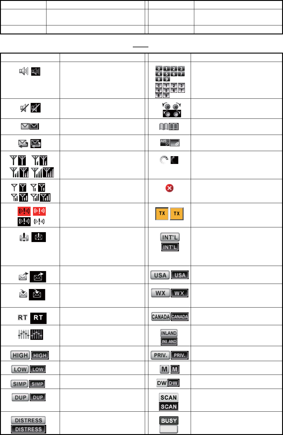
Icons
UTC Coordinated Universal Time/ Uni-
versal Time, Coordinated
VOL Volume
VDR Voyage Data Recorder WR Watchkeeping Receiver
Icon Meaning Icon Meaning
Speaker ON Number keys
Speaker OFF CHANNEL/ENTER knob
Unread message Name of the ship registered in
address book
Auto ACK for individual mes-
sage is ON.
Name of the ship registered in
AIS target list
Radio field intensity on the
RT screen
Data is being updated regular-
ly.
Radio field intensity on the
screens except the RT
screen
Unsolved error
Send a distress alert of your
ship.
Transmitting
• Receive a distress alert
from a ship in distress.
• Send a distress relay on
behalf of a ship in dis-
tress.
Channel region is INT’L.
Send a general (safety, ur-
gency or routine) message.
Channel region is USA.
Receive a general (safety,
urgency or routine) mes-
sage.
Channel region is WX.
Communicate via radiotele-
phone
Channel region is CANADA.
Equalizer mode is on. Channel region is INLAND-W.
Output power is high. Channel region is PRIVATE.
Output power is low. Channel region is MEMORY.
Simplex frequency Dual watching
Duplex frequency Scanning
Distress frequency Squelch is opened.
Abbreviation Term Abbreviation Term
AIS
BUSY

AP-15
APPENDIX 4 DIGITAL INTERFACE
(IEC 61162-1)
I/O Sentences
Input sentences (IEC 61162-1)
GGA, GLL, ZDA, GNS, RMC, VDM
Input sentence description
• GGA - Global positioning system (GPS) fix data
• GLL - Geographic position - latitude/longitude
• ZDA - Time and date
$**GGA,hhmmss.ss,llll.lll,a,yyyyy.yy,a,x,xx,x.x,x.x,M,x.x,M,x.x,xxxx*hh<CR><LF>
1 2 3 4 5 6 7 8 9 10 11 12 13 14
1. UTC of position (000000.00 - 235959.99)
2. Latitude (0000.0000 - 9000.0000)
3. N/S
4. Longitude (00000.0000 - 18000.0000)
5. E/W
6. GPS quality indicator (1 - 5)
7. Number of satllite in use (no use)
8. Horizontal dilution of precision (no use)
9. Antenna altitude above/below mean sealevel (no use)
10. Unit, m
11. Geoidal separation (no use)
12. Unit, m
13. Age of differential GPS data (no use)
14. Differential reference station ID (no use)
$**GLL,llll.ll,a,yyyyy.yy,a,hhmmss.ss,a,x*hh<CR><LF>
1 2 3 4 5
6 7
1. Latitude (0000.0000 - 9000.0000)
2. N/S
3. Longitude (00000.0000 - 18000.0000)
4. E/W
5. UTC of position (000000.00 - 235959.99)
6. Status (A=data valid V=data invalid)
7. Mode indicator (A=Autonomous D=Differential
N=No fix S=Simulator mode
$**ZDA,hhmmss.ss,xx,xx,xxxx,xx,xx*hh<CR><LF>
1 2 3 4 5 6
1. UTC (000000.00 - 235959.99)
2. Day (01 - 31)
3. Month (01 -12)
4. Year (2000 - 2049)
5. Local zone, hours (no use)
6. Loca zone, minutes (no use)

APPENDIX 4 DIGITAL INTERFACE (IEC 61162-1)
AP-16
• GNS - GNSS fix data
• RMC - Recommended minimum specific GNSS data
• VDM - UAIS VHF data-link message
$**GNS,hhmmss.ss,llll.ll,a,yyyyy.yy,a,c--c,xx,x.x,x.x,x.x,x.x,x.x,a*hh<CR><LF>
1 2
3 4 5 6 7 8 9 10 11 12 13
1. UTC of position (000000.00 - 235959.99)
2. Latitude (0000.0000 - 9000.0000)
3. N/S
4. Longitude (00000.0000 - 18000.0000)
5. E/W
6. Mode indicator
N=No fix A=Autonomous D=Differential P=Precise R=Real Time Kinematic
F=Float RTK S=Simulator Mode
7. Total number of satellites in use (00 - 99)
8. HDOP (no use)
9. Antenna altitude, meters (no use)
10. Geoidal separation (no use)
11. Age of differential data (no use)
12. Differential reference station ID (no use)
13. Navigational status indicator (S=Safe C=Caution U=Unsafe V=Navigational status not valid)
$**RMC,hhmmss.ss,A,llll.ll,a,yyyyy.yy,a,x.x,x.x,ddmmyy,x.x,a,a,a*hh<CR><LF>
1 2 3 4 5 6 7 8 9 10
11 12 13
1. UTC of position fix (000000.00 - 235959.99)
2. Status (A=data valid, V=navigation receiver warning)
3. Latitude (0000.0000 - 9000.0000)
4. N/S
5. Longitude (00000.0000 - 18000.0000)
6. E/W
7. Speed over ground, knots (no use)
8. Course over ground, degrees true (no use)
9. Date (010100 - 311249)
10. Magnetic variation, degrees (no use)
11. E/W
12. Mode indicator (A= Autonomous D= Differential
F=Float RTK N=No fix P=Precise R=Real time kinematic S= Simulator mode
13. Navigational status indicator (S=Safe C=Caution U=Unsafe V=Navigational status not valid)
$**VDM,x,x,x,a,s--s,x,*hh<CR><LF>
1 2 3 4 5 6
1. Total number of sentences needed to transfer the message (1 to 9)
2. Message sentence number (1 to 9)
3. Sequential message identifier (0 to 9, NULL)
4. AIS channel Number (A or B)
5. Encapsulated ITU-R M.1371 radio message (1 - 63 bytes)
6. Number of fill-bits (0 to 5)

APPENDIX 4 DIGITAL INTERFACE (IEC 61162-1)
AP-17
Output sentences (IEC 61162-1)
DSC, DSE, TLL
Output sentence description
• DSC - Digital selective calling information
• DSE - Expanded digital selective calling
• TLL - Target latitude and longitude
$CVDSC,xx,xxxxxxxxxx,xx,xx,xx,x.x,x.x,xxxxxxxxxx,xx,a,a*hh<CR><LF>
1 2 3 4 5 6 7 8 9
10 11
1. Format specifier (2 digits)
2. Address (10 digits)
3. Category (2 digits or NULL)
4. Nature of Distress or first telecommand (2 digits or NULL)
5. Type of Communication or second telecommand (2 digits)
6. Position or Channel /Frequency (Max. 12 digits)
7. Time or Tel. No. (Max. 16 digits)
8. MMSI of ship in distress (10 digits or NULL)
9. Nature of distress (2 digits or NULL)
10. Acknowledgement (R=Acknowledge request B=Acknowledgement S=Neither (end of sequence)
11. Expansion indicator (E or NULL)
$CVDSE,x,x,a,xxxxxxxxxx,xx,c--c,..........,xx,c--c*hh<CR><LF>
1 2 3 4 5 6 7 8 9
1. Total number of sentences (fixed value)
2. Sentence number (fixed value)
3. Query/reply flag (fixed value A=Automatic)
4. Vessel MMSI (10 digits)
5. Data set ‘1’ (code field, fixed value 00)
6. Data set ‘1’ (data field, Enhanced position resolution, Max. 8 characters), NULL
7. Additional data sets
*
, NULL
8. Data set ‘n’ (NULL)
*
9. Data set ‘n’ (NULL)
*
*
: This equipment outputs only “Data set 1”.
$CVTLL,xx,llll.ll,a,yyyyy.yy,a,c--c,hhmmss.ss,a,a*hh<CR><LF>
1 2 3 4 5 6 7 8 9
1. Target number, NULL
2. Latitude (0.0000 - 9000.0000)
3. N/S
4. Longitude (0.0000 - 18000.0000)
5. E/W
6. Target name, NULL
7. UTC of data (000000 - 235959)
8. Target status, NULL
9. Reference target, NULL
APPENDIX 4 DIGITAL INTERFACE (IEC 61162-1)
AP-18
P - sentences
pireq, pidat, CVdmr, CVdma
P - sentence description
• PFEC,pireq - Equipment information request
When this sentence is input, the equipment outputs the PFEC,pidat sentence.
• PFEC,pidat - Equipment information
• PFEC,CVdmr - Digital selective call Message call Request
• PFEC,CVdma - Digital selective call Message call Acknowledgement
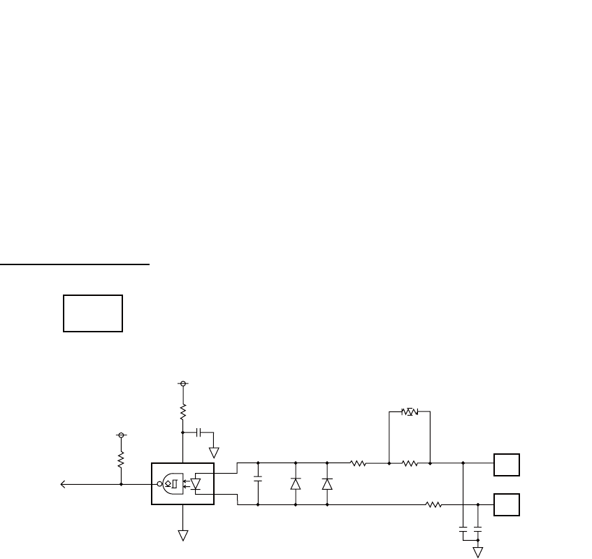
Schematic diagram
$ PFEC, pireq, sentence
$ PFEC, pidat, sentence
$ PFEC, CVdmr, sentence
$ PFEC, CVdma, sentence
+3.3V
GNSS_IN 43
1
5PC400
6
0.1
µ
2.2k
10
100p
1SS272
1SS272
0
100 330
MAIN
05P0843
GNSS_RD-H
GNSS_RD-C
21
22
1000p
10
1000p
[GNSS_SIO] Input only
+3.3V
(Not mount) J1
JUNCTION
APPENDIX 4 DIGITAL INTERFACE (IEC 61162-1)
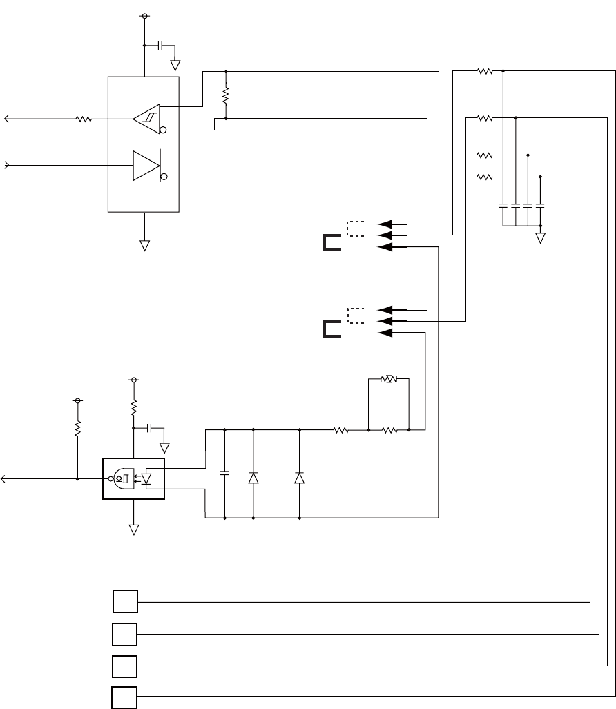
AP-19
Load requirements as a listener
Isolation: Optocoupler Input impedance: 430Ω Max. voltage: ±15 V Threshold: 4 mA
+3.3V
4
1
0.1
µ
RS422_RXD
RS422_TXD
22
2 R
3 D
VCCGND
SN65HVD30DR
A 8
B 7
Y 5
Z 6
120
0.5W
J17
Z_149_3P
1
2
3
RS-422
IEC61162-1
(default)
RS-422
J18
Z_149_3P
1
2
3
MULTI_RD-B
MULTI_RD-A
MULTI_TD-B
MULTI_TD-A
5PC400
6
0.1
µ
10
1
3
4
NMEA_RXD
2.2k
100p
1SS272
1SS272
100 330
0
10
10
13
14
10
15
10
16
[MULTI_SIO]
100px4
IEC61162-1
(default)
+3.3V
+3.3V
(Not mount)
(Not mount)
J1 JUNCTION
AP-20
APPENDIX 5 PARTS LIST
This equipment contains complex modules in which fault diagnosis and repair down to component
level are not practical (IMO A.694(17)/8.3.1). Only some discrete components are used. FURUNO
Electric Co., Ltd. Believes identifying these components is of no value for shipboard maintenance;
therefore, they are not listed in this manual. Major modules can be located on the parts location
photos on pages AP-21 thru AP-22.
Transceiver Unit FM-8900S
Handset HS-2003
Remote Handset HS-8900(-W)
Remote Handset Hanger HG-8900(-W)
Junction Box IF-8900
Unit
Code No.
ELECTRICAL PARTS LIST Transceiver Unit FM-8900S
05P0882, PANEL
05P0849, PWR
05P0843, MAIN
05P0841, TRX_WR
PRINTED CIRCUIT BOARD
Unit
Code No.
ELECTRICAL PARTS LIST Handset HS-2003
05P0780, HANDSET
PRINTED CIRCUIT BOARD
Unit
Code No.
ELECTRICAL PARTS LIST Remote Handset HS-8900(-W)
05P0781B, HS CONT
05P0715, KEY
PRINTED CIRCUIT BOARD
Unit
Code No.
ELECTRICAL PARTS LIST Remote Handset Hanger HG-8900(-W)
05P0798, TB
PRINTED CIRCUIT BOARD
Unit
Code No.
ELECTRICAL PARTS LIST Junction Box IF-8900
05P0850, JUNCTION
PRINTED CIRCUIT BOARD
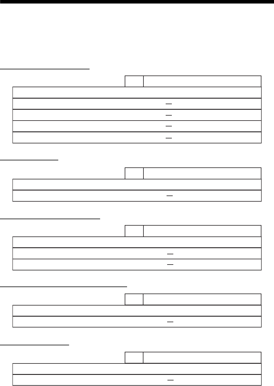
AP-21
APPENDIX 6 PARTS LOCATION
Transceiver unit FM-8900S
Handset HS-2003
05P0882
PANEL
Top cover removed
Back side of front panel
Bottom cover removed
05P0849
PWR
05P0841
TRX_WR
05P0843
MAIN
05P0780
HANDSET
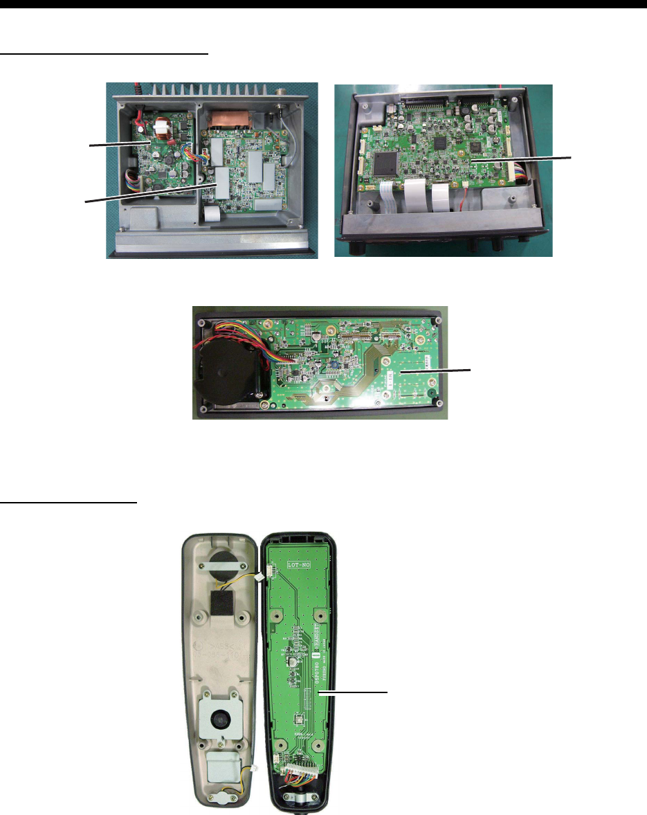
APPENDIX 6 PARTS LOCATION
AP-22
Remote station RB-8900 (HS-8900, HG-8900) / RB-8900-W (HS-8900-W, HG-8900-W)
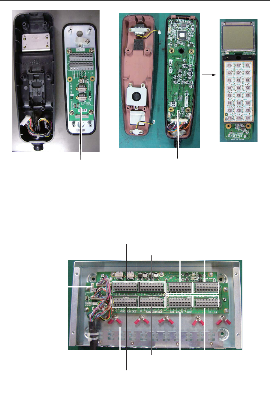
Junction box IF-8900
05P0798
TB
05P0781B
HS CONT
HG-8900
HG-8900-W
HS-8900
HS-8900-W
(Hanger) (Handset)
(Rear side)
05P0715
KEY
05P0850
JUNCTION
TB1
(REMOTE1)
TB3
(REMOTE3)
TB7
(ALARM SYSTEM/
INS/AIS/PLOTTER)
TB5
(ANALOG WING(LEFT)/VDR)
TB8
(ALARM UNIT)
TB6
(ANALOG WING(RIGHT)/GNSS)
TB4
(REMOTE 4)
TB2
(REMOTE 2)
Lug for connection
of shield of
TTYCSLA cables
FURUNO
FM-8900S
SP - 1 E5680S01E
SPECIFICATIONS OF MARINE VHF RADIOTELEPHONE
FM-8900S
1 GENERAL
1.1 Number of channels INTL: 57
USA: 50
Weather: 10
Canada: 57
INLAND-WA: 57
Private: 20
Memory CH: 50
1.2 Frequency stability Within ±1.5kHz
1.3 Communication system Simplex/Semi-duplex
1.4 Class of emission 16K0G3E (F3E) Voice, 16K0G2B (F2B) DSC
1.5 Antenna impedance 50 ohms
1.6 Display 4.3-inch color dot matrix LCD, 480 x 272 dots
1.7 Visible distance 0.7 m nominal
2 TRANSMITTER
2.1 Frequency range 155.000 to 161.475 MHz
2.2 Output power 25W max., 1W at power reduction
2.3 Frequency deviation Within ±5 kHz
3 RECEIVER
3.1 Frequency range Simplex: 155.000 to 161.475 MHz
Semi-duplex: 159.600 to 164.200 MHz
3.2 Receiving system Double superheterodyne
3.3 Intermediate frequency 1st: 51.1375 MHz, 2nd: 62.5 kHz
3.4 Sensitivity +6 dBμV or less (20 dB SINAD)
3.5 Channel selectivity 70 dB or more
3.6 Spurious response 70 dB or more
3.7 AF output Built-In speaker: 3W (4 ohms, THD: within 10%),
Handset earpiece: 2mW (150 ohms)
4 DSC
4.1 Protocol Rec. ITU-R M.541-9, M.493-13 (class A), M.689-2
4.2 Baud rate 1200 baud ±30 ppm max.
4.3 Modulation AFSK
4.4 Frequency of modulation 1700 ±400 Hz, Mark: 1300 Hz, Space: 2100 Hz
5 CH70 WATCH KEEPING RECEIVER
5.1 Receiving frequency 156.525 MHz
5.2 Receiving system Double superheterodyne
FURUNO
FM-8900S
SP - 2 E5680S01E
5.3 Intermediate frequency 1st: 38.3625 MHz, 2nd: 37.5 kHz
5.4 Sensitivity 0 dBμV or less (SER<1%)
5.5 Channel selectivity 70 dB or more
5.6 Spurious response 70 dB or more
6 INTERFACE
6.1 Navigation data IEC61162-1 Ed.4(2010-11)
Input sentences GGA, GLL, GNS, RMC, VDM, ZDA
Output sentences DSC, DSE, TLL
7 POWER SUPPLY
7.1 Power voltage 24 VDC (-10%, +30%)
7.2 Power consumption (with all options)
Transmit 4.7A max. at 25W output
Receive 2.3A max. at 4W audio output
Waiting 1.3A max.
8 ENVIRONMENTAL CONDITION
8.1 Ambient temperature -15°C to +55°C
8.2 Relative humidity 93% or less at +40°C
8.3 Degree of protection
Transceiver unit (FM-8900S) IP20 (IP22: option)
Handset/Hanger (HS-2003/FP05-05510) IP24
Remote station RB-8900: IP22, RB-8900-W: IP56
Junction box IP20, IP22 (bulkhead mount, option)
8.4 Vibration IEC 60945 Ed.4
9 COATING COLOR
9.1 Transceiver unit N2.5 (fixed)
9.2 Remote station/ handset N2.5 (fixed)
9.3 VHF console 7.5BG7/2, 2.5G7/2 or specified

IN-1
INDEX
A
Abbreviation ..........................................AP-13
Address book
deleting...................................................5-11
editing.....................................................5-10
list.............................................................5-8
registration ...............................................5-9
Alarm lists ................................................5-21
All ships message
receiving.................................................4-12
sending...................................................4-11
Audio alarms ..............................................2-2
Auto ACK setting......................................5-19
B
Brilliance
remote handset ........................................6-3
transceiver unit.........................................1-3
C
Channel region...........................................5-2
remote handset ........................................6-3
transceiver unit.........................................1-3
Channel selection
remote handset ........................................6-4
transceiver unit.........................................1-4
Contrast (remote handset) .........................6-3
Control description
remote handset ........................................6-1
transceiver unit.........................................1-1
D
Daily test ....................................................7-1
Date and time setting .................................5-5
Digital interface .....................................AP-15
Distress alert
canceling ................................................3-13
receiving...................................................3-4
sending.....................................................3-1
Distress relay
receiving.................................................3-13
sending...................................................3-10
DSC messages ..........................................2-1
Dual channels (DW) ...................................1-5
E
Error message ...........................................7-3
External alarm setting ................................5-7
G
Group message
receiving...................................................4-7
sending.....................................................4-6
Group message preparation ....................5-14
I
Icon .......................................................AP-14
Individual message
receiving...................................................4-4
sending.....................................................4-1
Individual message preparation ...............5-13
Intercom ............................................. 1-8, 6-5
L
Log file
deleting...................................................5-18
opening ..................................................5-17
M
Maintenance ..............................................7-2
Medical message
receiving.................................................4-19
sending...................................................4-18
Memory channel calling up
remote handset ........................................6-4
transceiver unit.........................................5-2
Memory configuration.................................5-3
MENU screen open/close ..........................5-1
Menu tree ................................................AP-1
N
Neutral message
receiving.................................................4-17
sending...................................................4-16
P
Parst list ................................................AP-20
Parst location ........................................AP-21
Polling request message..........................4-15
Position message
receiving.................................................4-15
sending...................................................4-13
Position setting...........................................5-4
Power on/off
remote handset ........................................6-2
transceiver unit.........................................1-2
Printing message .......................................5-4
Priority ........................................................1-7
Propose channel ......................................5-20
PSTN message
receiving.................................................4-10
sending.....................................................4-8
PSTN message preparation.....................5-15
R
Replay function ........................................1-12
RT application setting.................................5-8
RT screen
remote handset ........................................6-2
transceiver unit.........................................1-2
S
Scanning channels.....................................1-6
Session ......................................................1-9
INDEX
IN-2
Sound setting
remote handset ....................................... 6-6
transceiver unit ...................................... 5-20
Speaker
remote handset ....................................... 6-5
transceiver unit ........................................ 1-5
Special message..................................... 5-20
T
Test call..................................................... 7-4
Test message preparation ...................... 5-15
Timeout setting.......................................... 5-5
Transmission
remote handset ....................................... 6-4
transceiver unit ........................................ 1-4
Troubleshooting ........................................ 7-2
V
VHF channel lists ....................................AP-3