Furuno USA 9ZWRTR101 Transceiver for Radar model FAR-1518/1528 User Manual OME 36380 A
Furuno USA Inc Transceiver for Radar model FAR-1518/1528 OME 36380 A
Contents
- 1. Installation Manual Part 3
- 2. Installation Manual Part 1
- 3. Installation Manual Part 2
- 4. Installation Manual Part 4
- 5. Installation Manual Part 5
- 6. Installation Manual Part 6
- 7. User Manual Part 1
- 8. User Manual Part 2
- 9. User Manual Part 3
- 10. User Manual Part 4
- 11. User Manual Part 5
- 12. User Manual Part 6
User Manual Part 5
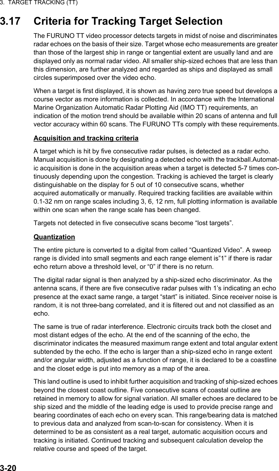
![3. TARGET TRACKING (TT)3-123.10.2 How to change the vector length (time)The vector time provides an estimation of the target’s vector and can be adjusted as follows:Place the cursor on the vector time indication in the [Vector] box, then press the left button. The vector time cycles through the following settings with each press of the left button.[6min] [10min] [20min] [30min] [45min] [60min] [30sec] [1min] [3min] [5min] [6min]...The vector tip shows an estimated position of the target after the selected vector time elapses. It can be valuable to extend the vector length to evaluate the risk of collision with any target.3.11 Past Position DisplayThe past position display shows equally time-spaced dots marking the past positions of any targets being tracked.A new dot is added every minute (or at other preset time intervals) until the preset number is reached. If a target changes its speed, the spacing will be uneven. If it changes the course, its plotted course will not be a straight line.Past position orientation, true or relative, is controlled with [TRAIL MODE] in the [TRAIL] context menu. To adjust the trail orientation, see paragraph 1.36.1.3.11.1 How to display past position points and select the past position plotting intervalPlace the cursor on the [PAST POSN] time indication in the [PAST POSN] box, then press the left button. The past position points are displayed and their plotting interval changes with each press of the left button, as shown below.[OFF] [30sec] [1min] [2min] [3min] [6min] [OFF]...3.11.2 How to select the number of past position points to be displayed1. Open the [MAIN MENU].2. Select [TT•AIS], then press the ADJUST knob.3. Select [TT•AIS SYMBOL], then press the ADJUST knob.4. Select [TT•AIS PAST POSN POINTS], then press the ADJUST knob.5. Select [5] or [10] as appropriate, then press the ADJUST knob.6. Close the menu.](https://usermanual.wiki/Furuno-USA/9ZWRTR101.User-Manual-Part-5/User-Guide-2768733-Page-1.png)
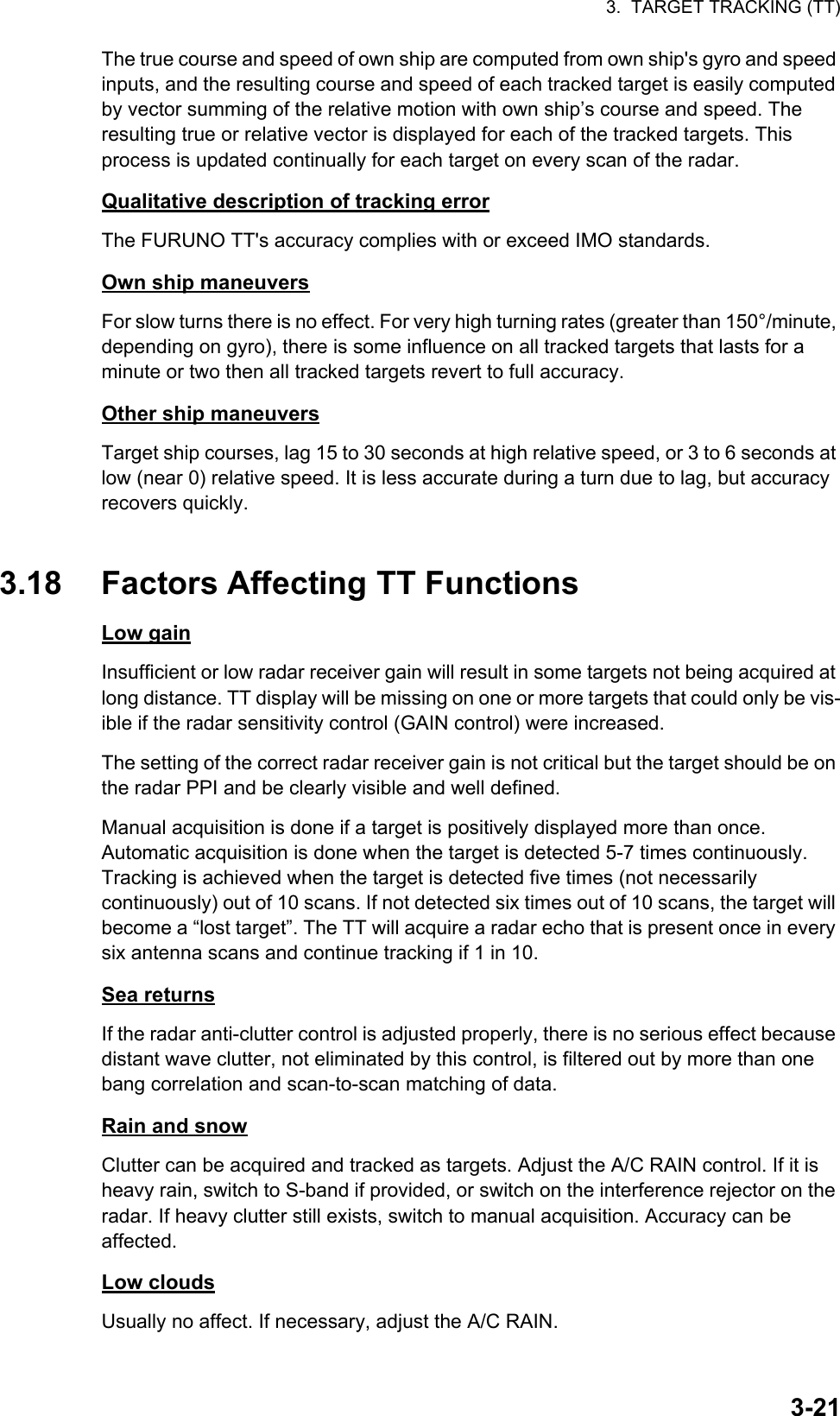
![3. TARGET TRACKING (TT)3-133.12 Set and DriftSet, the direction in which a water current flows, can be manually entered in 0.1-degree steps. Drift, also known as “Rate”, or the speed of the current, can also be entered manually in 0.1-knot steps.When course through water and speed through water are available, activate set and drift to get course over ground and speed over ground.Set and drift corrections are beneficial for increasing the accuracy of vectors and tar-get data. Refer to the tide table on board the ship for setting information. These values are applied to all targets. If stationary targets have vectors, set and drift values should be adjusted until they lose vectors.To enter set and drift do the following:1. Select the [SPD] menu box, then press the right button. The [SHIP SPEED MENU] is displayed.2. Select [SET DRIFT], then press the ADJUST knob.3. Select [ON], then press the ADJUST knob. The setting can now be adjusted and [SET] is selected.4. Rotate the ADJUST knob to select the appropriate setting (Setting range: 000.0° to 359.9°), then press the ADJUST knob. The [DRIFT] setting is now selected.5. Rotate the ADJUST knob to select the appropriate setting (Setting range: 00.0kn to 19.9kn), then press the ADJUST knob.6. Close the menu.Note 1: Set and drift are available when using manually input speed, speed through the water. The speed source is shown as "WTC" (Water Tracking Count).Note 2: Set and drift should be checked periodically for correctness.Note 3: When speed data input from the position sensor is valid, set and drift is not adjustable.](https://usermanual.wiki/Furuno-USA/9ZWRTR101.User-Manual-Part-5/User-Guide-2768733-Page-2.png)
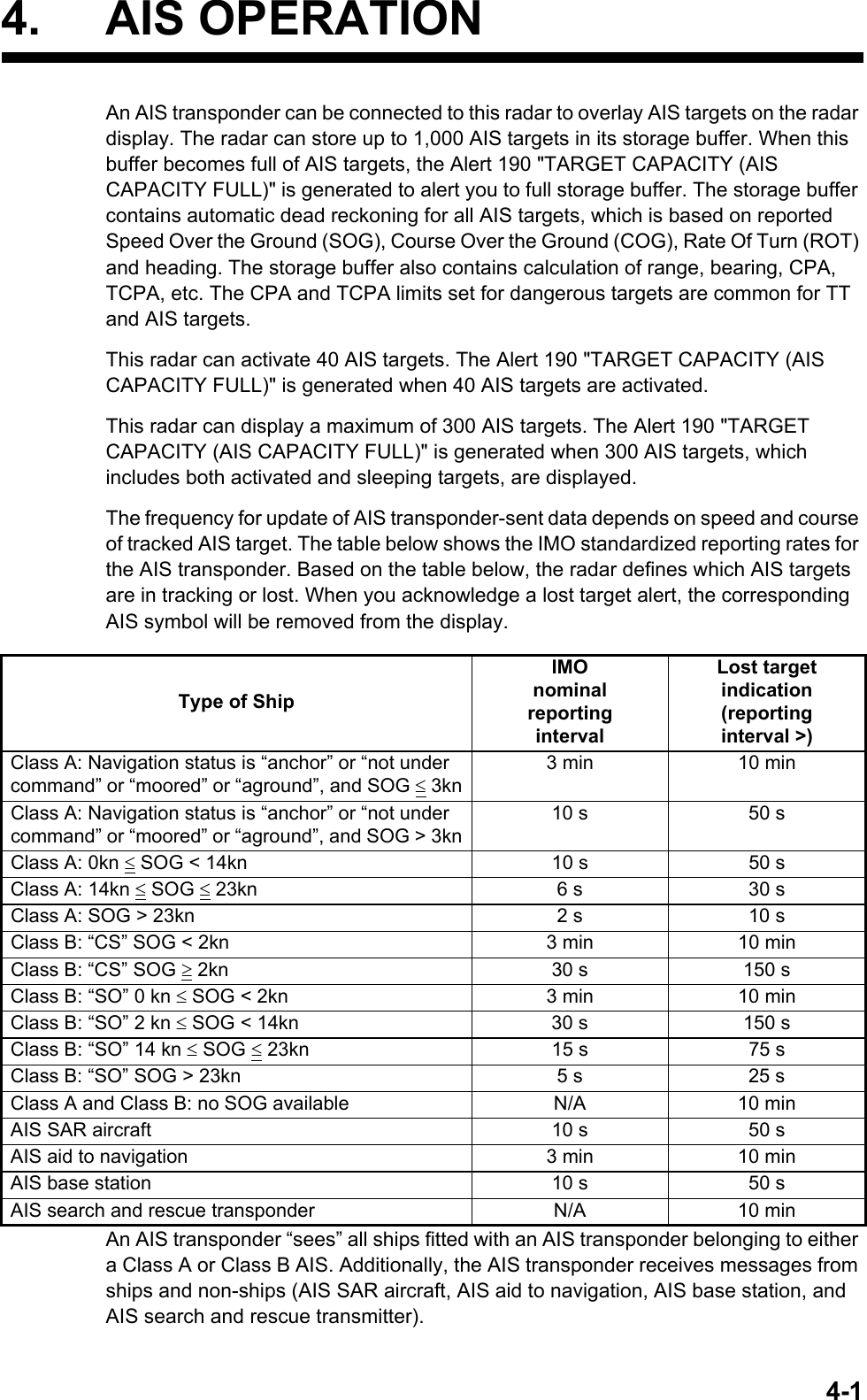
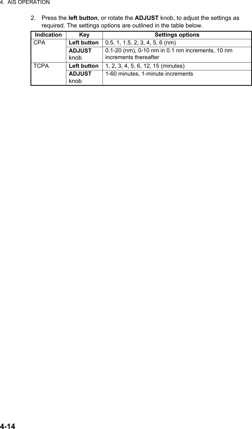
![3. TARGET TRACKING (TT)3-143.13 Collision Alarm (CPA, TCPA)This radar calculates CPA and TCPA by using own ship and relative target positions.The TT continuously monitors the predicted range at the Closest Point of Approach (CPA) and predicted time to CPA (TCPA) of each TT. When the predicted CPA of any TT becomes smaller than a preset CPA range and its predicted TCPA less than a preset TCPA limit, the audio alarm sounds and TT COLLISION appears (in red) in the Alert Box. In addition, the symbol of the offending TT is red and flashes together with its vector.This feature, when used correctly, helps prevent the risk of collision by alerting you to threatening targets. It is important that GAIN, A/C SEA, A/C RAIN and other radar controls are properly adjusted.CPA and TCPA ranges must be set up properly taking into consideration the size, ton-nage, speed, turning performance and other characteristics of own ship.The reference point for CPA and TCPA calculation can be selected from antenna position or conning position. For further details, see section 1.47.3.13.1 How to set the CPA and TCPA rangesCPA and TCPA ranges can be adjusted from the appropriate indication in the [TT] box.1. Place the cursor on the indication you wish to adjust.2. Press the left button, or rotate the ADJUST knob, to adjust the settings as required. The settings options are outlined in the table below.3.13.2 How to acknowledge the TT collision alarmPress the key on the control unit, or select the [ALERT] box with the Touchpad then press the left button to acknowledge the alarm and silence the buzzer. The alert "TT COLLISION" and the flashing of the plotting symbol and vector remain in the Alert Box until the dangerous situation is gone or you intentionally terminate tracking of the target.Note that when the TT COLLISION alarm is generated the AIS display is automatically turned on.Indication Key Settings optionsCPA Left button 0.5, 1, 1.5, 2, 3, 4, 5, 6 (nm)ADJUST knob 0.1-20 (nm), 0-10 nm in 0.1 nm increments, 10 nm increments thereafterTCPA Left button 1, 2, 3, 4, 5, 6, 12, 15 (minutes)ADJUST knob 1-60 minutes, 1-minute incrementsCAUTIONCPA/TCPA AlarmThe CPA and TCPA alarm feature shouldnever be relied upon as the sole means fordetecting the risk of collision.The navigatoris not relieved of the responsibility to keepvisual lookout for avoiding collisions,whether or not the radar or other plottingaid is in use.CPA settingTCPA setting](https://usermanual.wiki/Furuno-USA/9ZWRTR101.User-Manual-Part-5/User-Guide-2768733-Page-3.png)
![3. TARGET TRACKING (TT)3-153.14 Acquisition ZoneThe acquisition zone functions both to alert you targets in a specific area and acts as an automatic acquisition area when automatic target acquisition is active. Any targets entering the zone will be automatically acquired.When a target enters an acquisition zone, the buzzer sounds and the indication "TT NEW TARGET" (or "AIS NEW TARGET") appears (in yellow-orange) in the Alert Box. The symbol of the offending target is red and flashing. Further, the AIS display is automatically turned on if it is off.There are two types of acquisition zones available, arc and polygon, however, AZ1 can only be set as an arc.Note: The [AZ1] and [AZ2] boxes are not displayed when the setting for [AZ/ALR SELECT] in the [TT•AIS] menu is set to [TARGET ALARM ZONE].3.14.1 How to activate the first acquisition zone (AZ1)The No. 1 acquisition zone is available between 3 and 6 nm The TT/AIS acquisition zone’s lines are white and dashed so as to distinguish them from the radar target alarm.The procedure below shows how to set AZ1, using the example at the bottom of the page.1. Place the cursor on the [AZ] indication at the bottom-right of the screen.2. Press the left button to cycle through the settings and select [SET].3. Place the cursor on the acquisition zone starting point (“A” in the figure below), then press the left button.4. Place the cursor on the acquisition zone end point (“B” in the figure below), then press the left button.5. Press the right button to complete the acquisition zone set up.0.5-1 nm Target in acquision zone isred and flashing.AB](https://usermanual.wiki/Furuno-USA/9ZWRTR101.User-Manual-Part-5/User-Guide-2768733-Page-4.png)
![3. TARGET TRACKING (TT)3-163.14.2 How to set a polygon acquisition zone (AZ2)The No. 2 acquisition zone can be set anywhere when the No. 1 zone is already in use. Polygon zones must have at least three points.To set a polygon shaped acquisition zone:1. Place the cursor on the [AZ] indication at the bottom-right of the screen.2. Press the left button to cycle through the settings and select [SET].3. Place the cursor on the acquisition zone starting point, then press the left button.4. Place the cursor on the second point, then press the left button.5. Repeat step 4 as required to set the remaining points of the polygon zone.6. Press the right button to complete the acquisition zone set up.Notes on acquisition zones• If you wish to create an acquisition zone having a 360-degree coverage around own ship, set point B in almost the same direction (approx. ±3°) as point A, then press the left button.• The default acquisition zone is fan shaped. It can also be a polygon having 3-10 points.• If both acquisition zones are displayed, a maximum of four polygon points are shown.• TT and AIS are automatically set to TT=AUTO and AIS=DISP, respectively, when an AZ is activated in the following conditions: 3.14.3 How to sleep/deactivate an acquisition zone1. Select the appropriate [AZ] box.2. Sleep, or deactivate, the acquisition zone, as explained below:Sleeping the acquisition zonePress the left button several times until the indication shows "SLEEP".Deactivating the acquisition zonePress and hold the left button until the AZ box becomes blank.3.14.4 How to acknowledge the acquisition zone alertPress the key on the control unit, or select the [ALERT] box with the Touchpad then press the left button to acknowledge the alarm and silence the buzzer.TT : TT=OFF or TT=MANUAL 50AIS : AIS FUNC=OFF or AIS DISP=OFF](https://usermanual.wiki/Furuno-USA/9ZWRTR101.User-Manual-Part-5/User-Guide-2768733-Page-5.png)
![3. TARGET TRACKING (TT)3-173.14.5 How to change the acquisition zone referenceThe acquisition zone can be referenced to heading or North using the following procedure:1. Open the [MAIN MENU].2. Select [TT•AIS], then press the ADJUST knob.3. Select [ACQUISITION ZONE], then press the ADJUST knob.4. Select [AZ STAB], then press the ADJUST knob.5. Select [STAB HDG] to reference heading, or [STAB NORTH] to reference North.6. Close the menu.3.14.6 How to set acquisition zone shape and stabilizationThe shape of the No. 2 acquisition zone can be a sector or a polygon having up to 10 points. (The shape of the No.1 acquisition zone is always a sector.)1. Open the [MAIN MENU].2. Select [TT•AIS], then press the ADJUST knob.3. Select [ACQUISITION ZONE], then press the ADJUST knob.4. Select [AZ POLYGON], then press the ADJUST knob.5. Select the appropriate setting, then press the ADJUST knob.6. Close the menu.Setting Description[OFF] Acquisition zone is a sector; number of points is limited to four. Stabilized against land.[STAB GND] Polygon having 3-10 points. Stabilized against ground.[STAB HDG] Polygon having 3-10 points. Stabilized against heading.[STAB NORTH] Polygon having 3-10 points. Stabilized against North.](https://usermanual.wiki/Furuno-USA/9ZWRTR101.User-Manual-Part-5/User-Guide-2768733-Page-6.png)
![3. TARGET TRACKING (TT)3-183.15 TT System MessagesThere are four main reasons the TT may trigger the audio and visual alerts:• Collision alarm• Acquisition zone alert• Lost target alert• Target capacityTo acknowledge the alert, press the key on the control unit, or select the [ALERT] box with the Touchpad then press the left button to acknowledge the alert and silence the buzzer.Alert message Priority Meaning Action requiredTT COLLISION Alarm A tracked target is on collision course with your vessel.Take evasive action or terminate tracking of TT.TT NEW TARGETWarning Tracked target has entered an acquisition zone. The tracked target's symbol is red and flashing.Confirm the tracked target, then press the key.TT LOST Warning When the system detects a loss of a tracked target, the lost tracked target symbol appears in red and flashes. At the same time, an audio alert is produced for one second. The lost target mark disappears from the screen after the lost target alert is acknowledged.Confirm the lost target, re-acquire if necessary.REF TARGET LOSTWarning When the system detects a loss of a reference target, the target symbol turns red and flashes. At the same time, an audio alert is produced for one second. The reference target mark disappears from the screen after the reference target alarm is acknowledged.To continue using a referenced target for speed input, select another tracked target.TT TARGET FULL (AUTO) or (MAN)Warning Appears when capacity for automatically (manually) acquired targets is full.To continue acquiring targets, cancel tracking for unnecessary targets.TT TARGET 95% (AUTO) or (MAN)Caution Appears when capacity for automatically (manually) tracked targets is 95% full.](https://usermanual.wiki/Furuno-USA/9ZWRTR101.User-Manual-Part-5/User-Guide-2768733-Page-7.png)
![3. TARGET TRACKING (TT)3-193.16 TT Simulation ModeYou can simulate the risk of a collision by using the TT simulation mode. The test can be terminated at any time by pressing the key.1. Open the [MAIN MENU].2. Select [INTIAL SETTING], then press the ADJUST knob.3. Select [TEST], then press the ADJUST knob.4. Select [TT TEST], then press the ADJUST knob.The normal operation is suspended then three simulated targets appear on the dis-play.The indication "S" appears at the bottom of the effective display area during the sim-ulation mode. The simulation may be terminated any time by going to the STBY mode.Three simulated targets move as the following table. The simulated target is automat-ically generated with the relative movement in the following table based on own ship's movement at the start of simulation mode.Note: If own ship moves after the start of simulation mode, the movement of the sim-ulated target is not matched with the values in the following table.Place the cursor on a target, then press the key to display the target data.Acquire the simulated targets after the TT simulation mode is performed. The tracking state changes from unstable to stable and the vector appears. You can simulate the movement of each function with changing true/relative vector, stabilization through the water/over the ground, range or length of vector.Repeat the check for all targets.Range (R) Bearing (R) Speed (R) Course (R) CPA TCPATarget 01 9.5 NM 270.0° 20.0 kn 90.0° 0.0 NM 28.5 minTarget 02 1.1 NM 333.0° 10.2 kn 90.2° 1.0 NM 2.9 minTarget 03 9.3 NM 45.0° 19.9 kn 225.1° 0.0 NM 28.0 minS010302](https://usermanual.wiki/Furuno-USA/9ZWRTR101.User-Manual-Part-5/User-Guide-2768733-Page-8.png)
![3. TARGET TRACKING (TT)3-22Non-synchronous emissionsNo effect.Second trace echoesWhen the radar beam is super refracted, strong echoes may be received at such long ranges that they appear on a different timebase sweep than the transmitted pulse. This gives an incorrect range indication. Second and third trace echoes can be tracked if they are consistent enough to meet acquisition and tracking criteria but target course and speed data will be in error.Blind and shadow sectorsRadar shadow or blind areas caused by obstructions aboard ship, for example, fun-nels and masts, in the path of the radar beam can result in reduction of radar beam intensity in that particular direction. This may eliminate the detection of some targets. The TT system will lose track of targets shortly after they are lost on the radar picture and if they remain in a blind zone. These targets will however be acquired and tracked when they pass out of the blind zone and again present normal radar echo. The an-gular width and bearing of any shadow sector should be determined for their influence on the radar. In certain cases false echoes in the shadow sector cause the TT system to acquire, track, and vector them. Shadow sectors should be avoided.Indirect echoesA target at close range is usually picked up directly, but it can also be received as reflection from a large, flat surface. This will result in the radar presenting two or more echoes on the display, each at a different range. The TT can acquire and track the false echo if it is detected by five consecutive scans. Reduction in radar gain can eliminate the multiple echoing but care should be taken as range detection also will be reduced.Radar interferenceIf interference is extreme due to another radar operating at close range, spiral “dotting” and/or false targets may appear momentarily. The interference rejector can clear the display.To receive radar beacon or SART signals, turn on [SART] in the [ECHO] menu.](https://usermanual.wiki/Furuno-USA/9ZWRTR101.User-Manual-Part-5/User-Guide-2768733-Page-11.png)
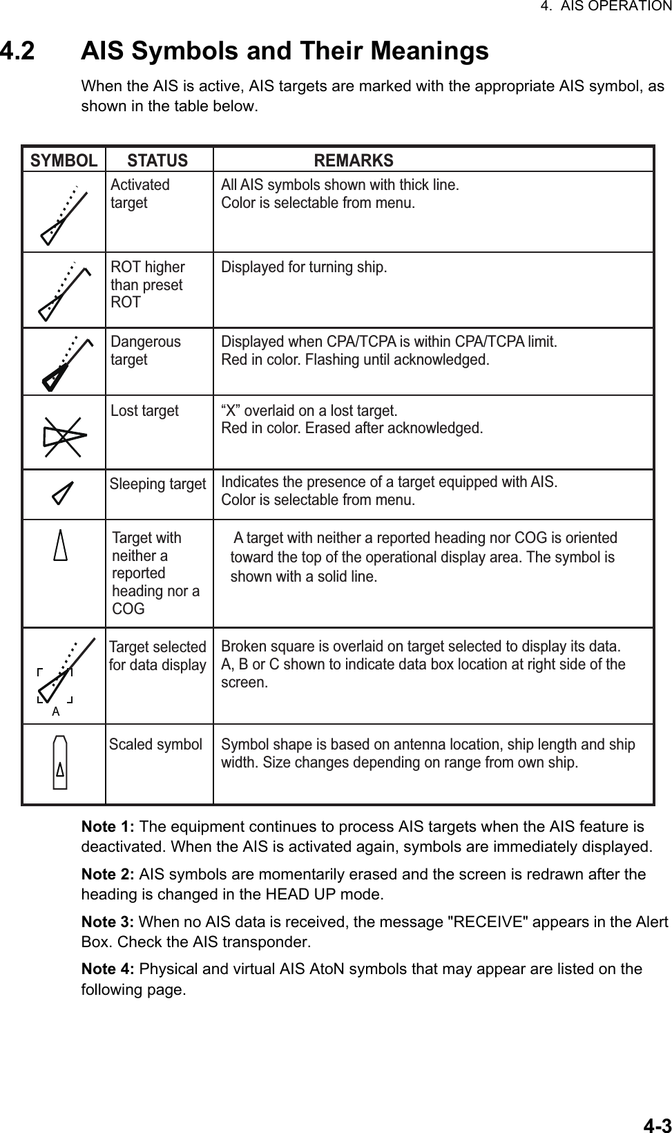
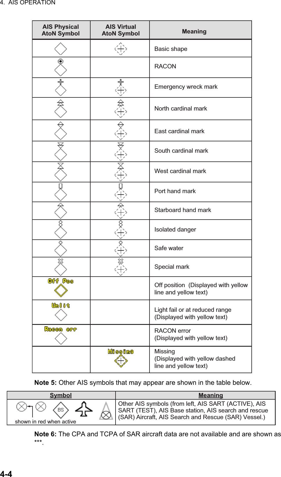
![4. AIS OPERATION4-24.1 Controls for AIS• TGT ACQ: Displays the selected target’s data.• TGT CANCEL: Sleeps the cursor-selected target.These functions, along with other AIS functions, can also be accessed from the [CURSOR] menu (See section 1.7).There can be several hundreds or several thousands of AIS targets, and of those only a few will be significant for your ship. To remove unnecessary AIS targets from the radar display, the feature “active and sleeping AIS targets” is available. Initially any new AIS target received by an AIS transponder is not active (=“sleeping”). Such sleeping targets are shown with a small triangle. The operator can pick any AIS target and change it from sleeping to active. Active AIS targets are shown with a large triangle with speed vector, headline, ROT indicator, etc. Further, the operator can pick active AIS targets and change their status to sleeping.An indication of AIS target activated capacity limit is given well before it is reached. When 95% of 40 targets are activated, the Alert 190 "TARGET CAPACITY (AIS ACITVATE 95%)" appears. When 40 targets are activated, the Alert 190 "TARGET CAPACITY (AIS ACTIVATE FULL)" appears.An indication of AIS target display capacity limit is given well before it is reached. When 95% of 300 targets are displayed, the Alert 190 "TARGET CAPACITY (AIS ACTIVATE 95%)" appears. When 300 targets are displayed, the Alert 190 "TARGET CAPACITY (AIS DISPLAY FULL)" appears.An indication of AIS target processing capacity limit is given well before it is reached. The Alert 190 "TARGET CAPACITY (AIS CAPACITY FULL)" appears when 1,000 targets are in the storage buffer.This radar generates AIS-related alerts. These are Alert 191 "CPA/TCPA (AIS COLLISION" and Alert 193 "LOST TARGET (AIS LOST)". Only active AIS targets generate alerts. The operator can activate or sleep AIS target alerts as desired. The feature “active and sleeping AIS targets” is very effective for focusing on only those AIS targets that need supervision. This radar further eases the task of the operator by automatically changing non-active targets to active targets, if their CPA and TCPA are within a preset limit.Displays AIS target data Cancel targetSelect the AIS box, then press the left button to cycle through AIS display modes.DISP OFF: Hides AIS targetsDISP FILT: Displays a filtered selection of AIS targetsDISP ALL: Displays all AIS targetsFUNC OFF: Deactivates the AIS function](https://usermanual.wiki/Furuno-USA/9ZWRTR101.User-Manual-Part-5/User-Guide-2768733-Page-13.png)
![4. AIS OPERATION4-54.3 How to Use the AIS Display FilterIf there are too many AIS targets on the screen you may wish to remove unnecessary ones. You can remove sleeping targets A/B by distance from own ship, speed and class. For example, you might want to remove slow moving targets, as they normally do not require close monitoring.1. Open the [MAIN MENU].2. Select [TT•AIS], then press the left button.3. Select [AIS DISP FILTER], then press the left button.4. Referring to the table below, select the appropriate filtering type, then press the left button.5. Rotate the ADJUST knob to set the selected filter’s options, then press the ADJUST knob.6. Close the menu.7. Place the cursor on the [AIS] box, then press the left button several times to dis-play "DISP FILT" in the [AIS] box.Note: This function is not available for an activated target.4.4 How to Activate AIS TargetsWhen you convert a sleeping target to an activated target, that target’s course and speed are shown with a vector. You can easily judge target movement by monitoring the vector.Sleeping targets within an acquisition zone are automatically changed to activated targets and are colored red. See section 3.14 for how to use acquisition zones.4.4.1 How to activate specific targets manuallyPlace the cursor on the target you wish to activate for AIS tracking, then press the left button.Filter type Definition[MAX RANGE] Any sleeping AIS targets class A/B beyond the range set here will not be shown.[MIN SHIP SPEED] Any sleeping AIS targets class A/B slower than this setting will not be shown.[EXCEPT CLASS B] Select [ON] to remove sleeping AIS targets class B.[EXCEPT BASE STATION] Select [ON] to remove the BASE STATION symbol.[EXCEPT PHYSICAL ATON] Select [ON] to remove the AIS PHYSICAL ATON symbol.[EXCEPT VIRTUAL ATON] Select [ON] to remove the AIS VIRTUAL ATON symbol.SOG (Speed Over Ground) and COG (Course Over Ground) vector *1*1 Vector shows STW (Speed Thru Water) and CTW (Course Thru Water) when water tracking mode is selected at the radar.Turning direction (ROT)Heading line *2*2 If there is no heading data available, the heading line is not displayed.](https://usermanual.wiki/Furuno-USA/9ZWRTR101.User-Manual-Part-5/User-Guide-2768733-Page-16.png)
![4. AIS OPERATION4-64.4.2 How to enable/disable the AIS auto activate functionUse the [CPA AUTO ACTIVATE] box at the bottom right corner to enable or disable the AIS auto active function.1. Place the cursor on the [CPA AUTO ACTIVATE] box, then press the left button several times to display the desired auto activate function.4.4.3 How to limit the functions of the AIS auto activate functionYou can limit the function of the AIS auto active function by distance from own ship, ship's speed, ship class, and ship's length.1. Open the [MAIN MENU].2. Select [TT•AIS], then press the ADJUST knob.3. Select [CPA AUTO ACTIVATE], then press the ADJUST knob.4. Referring to the table below, select the appropriate filtering type, then press the ADJUST knob.5. Rotate the ADJUST knob to set the selected filter’s options, then press the ADJUST knob.6. Close the menu.Filter type Definition[OFF] Disable the AIS auto activate function.[AUTO ACT ALL] Activation against AIS targets whose CPA or TCPA is less than set in section 3.13[AUTO ACT FILT] Activation against AIS targets which meet the following criteria:• AIS target that meets the criteria set with [CPA AUTO ACTIVATE] on the [TT•AIS] menu.• CPA or TCPA of an AIS target is smaller than that set in section section 3.13.Filter type Definition[MAX RANGE] Any AIS targets beyond the range set here will not be automatically activated.[MIN SHIP SPEED] Any AIS targets slower than this setting will not be automatically activated.[EXCEPT CLASS B] Select ON to prevent activation of AIS targets class B.Select the AIS CPA box, then press the left button to cycle through AIS display modes.](https://usermanual.wiki/Furuno-USA/9ZWRTR101.User-Manual-Part-5/User-Guide-2768733-Page-17.png)
![4. AIS OPERATION4-74.5 How to Sleep AIS Targets4.5.1 How to sleep individual AIS targetsYou can “sleep” an AIS target as below when the screen becomes filled with targets, which might prevent important radar and AIS displays from being identified. Note: Targets that have been activated automatically cannot be “slept”.1. Place the cursor on the target to be slept, then press the key. The symbol for the slept target changes as indicated in the table in section 4.2.4.5.2 How to sleep all AIS targets1. Select the [AIS DISP] box, then press the right button to open the [AIS TARGET] menu.2. Select [SLEEP ALL TGTS], then press the ADJUST knob.3. Select [YES] or [NO] as appropriate, then press the ADJUST knob.4. Close the menu.4.6 How to Set Up For a VoyageAt the start of a voyage, following five items must be input from the [VOYAGE DATA] menu: navigational status, ETA, destination, draught and crew.1. Select the [AIS DISP] box, then press the right button to open the [AIS TARGET] menu.2. Select [VOYAGE DATA], then press the ADJUST knob.3. Select [NAV STATUS], then press the ADJUST knob.4. Select the appropriate navigation status number, referring to the table below, then press the ADJUST knob.Nav Status No.Meaning00 Underway using engine (default)01 At anchor02 Not under command03 Restricted maneuverability04 Constrained by her draft05 Moored06 Aground07 Engaged in fishing08 Under way sailing09 Reserved for high speed craft (HSC)10 Reserved for wing in ground (WIG, for example, hydrofoil)11 Power-driven vessel (ahead/astern)12 Power-driven vessel (ahead/alongside)13 Reserved for future useContinued on following page.](https://usermanual.wiki/Furuno-USA/9ZWRTR101.User-Manual-Part-5/User-Guide-2768733-Page-18.png)
![4. AIS OPERATION4-85. Select [ETA], then press the ADJUST knob.6. Using the ADJUST knob, set the estimated day of the month to arrive, then press the ADJUST knob.7. Select [DESTINATION], then press the left button.8. Using the ADJUST knob, set the destination in alphanumeric characters, then press the ADJUST knob. (Max. 20 characters)9. Select [DRAUGHT], then press the ADJUST knob.10. Using the ADJUST knob, set the ship’s draught, then press the ADJUST knob.11. Select [CREW], then press the ADJUST knob.12. Using the ADJUST knob, set the number of crew on-board, then press the ADJUST knob.13. Close the menu.Continued from previous page.14 AIS SART (No use)15 AIS SART TESTNav Status No.Meaning08Currently selected digit is highlighted by the cursor.Rotate the ADJUST Rotokey to adjust the day.Press the ADJUST Rotokey to move to the next digit.GOLD COASTCurrently selected character is highlighted by the cursor.Rotate the ADJUST Rotokey to select the desired character.Press the ADJUST Rotokey to move to the next character.](https://usermanual.wiki/Furuno-USA/9ZWRTR101.User-Manual-Part-5/User-Guide-2768733-Page-19.png)
![4. AIS OPERATION4-94.7 Target DataYou can display an AIS target’s data by selecting it on the display, when the AIS function is set for [AIS DISP FILT].4.7.1 How to display target data in the data display areaPlace the cursor on a desired tracked target and press the key. The target is highlighted with square box and the selected AIS target’s data is shown in AIS target data box in the data display area, on the right side of the screen.4.7.2 How to remove target data from the display areaPlace the cursor on a desired tracked target and press the key. The select tar-get’s data is no longer displayed in the data display area. Location of target data boxTarget’s MMSI IDName of targeted shipBearing to targetRange to targetTarget’s courseTarget’s speedTarget’s CPATarget’s TCPATarget’s bow cross rangeTarget’s bow cross timeTarget’s coordinatesTarget’s headingTarget’s rate of turnTarget’s nav statusAAIS target data box](https://usermanual.wiki/Furuno-USA/9ZWRTR101.User-Manual-Part-5/User-Guide-2768733-Page-20.png)
![4. AIS OPERATION4-104.8 How to Adjust AIS Symbol AttributesThe AIS symbol’s brilliance, size and color can be adjusted.4.8.1 How to adjust the AIS symbol brilliance1. Place the cursor on the [BRILL] box, then press the right button. The [BRILL] menu is displayed.2. Select [AIS SYMBOL], then press the ADJUST knob.3. Using the ADJUST knob, adjust the brilliance to the appropriate level, then press the ADJUST knob.4. Press the right button to close the menu.4.8.2 How to adjust the AIS symbol color1. Open the [MAIN MENU].2. Select [TT•AIS], then press the ADJUST knob.3. Select [TT•AIS SYMBOL], then press the ADJUST knob.4. Select [SYMBOL COLOR], then press the ADJUST knob.5. To cycle through the colors for the AIS symbols, rotate the ADJUST knob.To select the color, press the ADJUST knob. The available colors, in order, are:[GRN] (Green) [BLU] (Blue) [CYA] (Cyan) [MAG] (Magenta) [WHT] (White) [GRN]...6. Select [AIS SCALED SYMBOL], then press the ADJUST knob.7. Select [OFF] or [ON] as appropriate, then press the ADJUST knob.[OFF]: All AIS symbols are displayed in the same size.[ON]: AIS symbols are displayed in scale, according to the ship length.The figure to the right shows examples of standard and scaled symbols.8. Close the menu.4.8.3 How to adjust the ATON symbol color1. Open the [MAIN MENU].2. Select [TT•AIS], then press the ADJUST knob.3. Select [TT•AIS SYMBOL], then press the ADJUST knob.4. Select [ATONSYMBOL COLOR], then press the ADJUST knob.5. To cycle through the colors for the ATON symbols, rotate the ADJUST knob.To select the color, press the ADJUST knob. The available colors, in order, are:[GRN] (Green) [BLU] (Blue) [CYA] (Cyan) [MAG] (Magenta) [WHT] (White) [GRN]...6. Close the menu.Standard symbolScaled symbol](https://usermanual.wiki/Furuno-USA/9ZWRTR101.User-Manual-Part-5/User-Guide-2768733-Page-21.png)
![4. AIS OPERATION4-114.9 Past Position Display4.9.1 How to adjust the past position plotting intervalThe plotting interval determines how often the target’s past position is refreshed. To change the plotting interval do the following:Place the cursor on the plotting interval for the [Past POSN] indication in the [TT•AIS] box, then press the left button to cycle through the intervals.The available options, in order, are:[OFF] [30 SEC] [1 MIN] [2 MIN] [3 MIN] [6 MIN] [OFF]...To erase all past position points and disable the past position display, select [OFF].4.9.2 How to select the number of past position points to be displayed1. Open the [MAIN MENU].2. Select [TT•AIS], then press the ADJUST knob.3. Select [TT•AIS SYMBOL], then press the ADJUST knob.4. Select [TT•AIS PAST POSN POINTS], then press the ADJUST knob.5. Select [5] or [10] as appropriate, then press the ADJUST knob.6. Close the menu.4.9.3 Past position display orientationPast position orientation, true or relative, is controlled with [TRAIL MODE] in the [TRAIL] context menu. To adjust the trail orientation, see paragraph 1.36.1.4.9.4 Stabilization in true motionTrue motion past position display can be ground stabilized or sea stabilized. The [TRAIL] box shows current stabilization as "TRUE-G" or "TRUE-S". To change stabilization mode, open the [SHIP SPEED MENU] menu and set [SHIP SPEED] to [LOG(BT)] (ground stabilization) or [LOG(WT)] (sea stabilization).The past position display shows equally time-spaced dots marking past positions of ac-tivated AIS targets. A new dot is added at preset time intervals until the preset number is reached. If a target changes its speed, the spacing will be uneven. If it changes course, its plotted course will not be a straight line.Below are examples of past position displays.(a) Ship turning (b) Ship running straight (c) Ship reduced speed (d) Ship increased speedPast POSN indication Plotting interval](https://usermanual.wiki/Furuno-USA/9ZWRTR101.User-Manual-Part-5/User-Guide-2768733-Page-22.png)
![4. AIS OPERATION4-124.10 Lost TargetA target is declared a lost target when it fails to produce data for six minutes or five reporting intervals, whichever is the shorter. When this occurs, the target is marked with the (flashing) lost target symbol and the message "LOST" appears in the Alert Box. To acknowledge a lost target, press the key, or use the Touchpad to se-lect the [ALERT] box then press the left button.4.10.1 How to set the lost target filterIf there are a lot of AIS targets in your area, the lost target alert can sound frequently. In this case you may wish to have the alert ignore lost targets whose range, speed, class or length are below the threshold value you specify.1. Open the [MAIN MENU].2. Select [TT•AIS], then press the ADJUST knob.3. Select [AIS LOST FILTER], then press the ADJUST knob.4. Referring to the table below, select the appropriate filtering type, then press the ADJUST knob.5. Select [ON], then press the ADJUST knob. The settings can now be adjusted.6. Rotate the ADJUST knob to adjust the setting as required, then press the ADJUST knob to apply the setting.7. Close the menu.4.10.2 How to enable/disable the lost target alertThe [LOST TARGET ALERT] box at the bottom right corner enables and disables the lost target alert. Select the box with the cursor, then press the left button to select [OFF], [ALL] or [FILT] as appropriate.• [OFF]: Disable the alert.• [ALL]: Enable the alert for all lost targets, including filtered targets.• [FILT]: Enable the alert for all lost targets, excluding filtered targets.Filter type Definition[MAX RANGE] Any AIS targets beyond the range set here will not trigger the lost target alert.[MIN SHIP SPEED] Any AIS targets slower than this setting will not trigger the lost target alert.[EXCEPT CLASS B] Select ON to prevent AIS targets class B triggering the lost target alert.[MIN SHIP LENGTH] Any AIS targets whose length is shorter than this setting will not be automatically activated.Lost target alert box](https://usermanual.wiki/Furuno-USA/9ZWRTR101.User-Manual-Part-5/User-Guide-2768733-Page-23.png)
![4. AIS OPERATION4-134.11 ROT SettingYou can set the lower limit of the ROT (Rate Of Turn) at which the heading line on target symbols will point in direction of turning of the vessel.ROT display1. Open the [MAIN MENU].2. Select [TT•AIS], then press the ADJUST knob.3. Select [TT•AIS SYMBOL], then press the ADJUST knob.4. Select [AIS ROT TAG LIMIT], then press the ADJUST knob. The settings can now be adjusted.5. Using the ADJUST knob, adjust the ROT as appropriate. Rotate the ADJUST knob to adjust the value, press the ADJUST knob to move to the next digit. The setting range is 000.0°/min to 720.0°/min.6. Close the menu.4.12 AIS Collision Alarm (CPA, TCPA)This radar calculates CPA and TCPA by using own ship and relative target positions. An AIS dangerous target is one whose CPA and TCPA are within the range of the CPA and TCPA limits set in the TT/AIS box. The AIS symbol of an AIS dangerous target is red and flashing, and is announced with the Alert 536 "AIS CPA/TCPA". After the alert is acknowledged the target symbol is displayed in red color.4.12.1 How to set the CPA and TCPA rangesCPA and TCPA ranges can be adjusted from the appropriate indication in the [TT•AIS] box. If the CPA/TCPA settings are displayed as “OFF”, place the cursor on the CPA limit indication, then press the left button.1. Place the cursor on the indication you wish to adjust.Ship turning to starboardThicker thanactivated targetWhen a sleeping or an activated target violates the CPA/TCPA alarm setting its symbol changes to the dangerous target symbol (red and flashing) and the message AIS COLLISON appears. Press the ALARM ACK key (or click the [ALERT] box with the left button) to acknowledge the CPA/TCPA alarm. The audible alarm is silenced and the symbol stops flashing.Take appropriate action to avoid collision.Dangerous targetCPA settingTCPA setting](https://usermanual.wiki/Furuno-USA/9ZWRTR101.User-Manual-Part-5/User-Guide-2768733-Page-24.png)
![4. AIS OPERATION4-154.13 How to associate TT and AIS TargetsAn AIS-equipped ship is usually displayed by two symbols on the radar display. This is because the AIS ship position is measured by a GPS navigator (L/L) whereas the radar detects the same ship by PPI principle (range and bearing relative to own ship radar antenna). To avoid the presentation of two target symbols for the same physical target, use the "association" function. If target data from both AIS and TT are available and if the as-sociation criteria are fulfilled, either the AIS or TT symbol is presented according to the association method selected.Association will not happen between AIS and TT if the AIS target is sleeping or the AIS target is lost.1. Confirm that the [TT ACQ MODE] indication shows "AUTO", "AUTO MAN" or "MAN".2. Open the [MAIN MENU].3. Select [TT•AIS], then press the ADJUST knob.4. Select [ASSOCIATION], then press the ADJUST knob.5. Select [ASSOCIATION TGT], then press the ADJUST knob.6. Select [OFF], [AIS] or [TT], as appropriate, to select which symbols and data to display when the association criteria are met.• [OFF]: Disable association.• [AIS]: Use AIS symbols and AIS data.• [TT]: Use TT symbols and TT data.Note: Association can also be switched on and off from the screen by left-clicking the Association Usage icon, shown below.7. Referring to the table below, set the association criteria. Rotate the ADJUST knob to adjust the value, press the ADJUST knob to move to the next digit.8. Close the menu.[GAP]: Range in bearing direction between AIS target and tracked target.(setting range: 0.000-0.050 (nm))[RANGE]: Range direction difference from own ship to AIS target and tracked target. (setting range: 0.000-0.100 (nm))[BEARING]: Bearing difference from own ship to AIS target and tracked target. (setting range: 0.0-9.9 (°))[SPEED]: Speed difference between AIS target and tracked target. (setting range: 0.0-6.0 (kn))[COURSE]: Course difference between AIS target and tracked target. (setting range: 0.0-25.0 (°))TT ACQ MODE indicationPlace the cursor on the association icon, then press the left button to change the association setting.>: Use TT Symbols and data.<: Use AIS symbols and data.No indication: Association is disabled.](https://usermanual.wiki/Furuno-USA/9ZWRTR101.User-Manual-Part-5/User-Guide-2768733-Page-26.png)
![4. AIS OPERATION4-16When the association criteria (gap, range, bearing, speed, and course) is met, and the ASSOCIATION TARGET setting is [AIS], the TT symbol is erased and only the AIS symbol is displayed. Further, "ASSOCIATION" appears in the Alert Box.All default association settings are restored whenever the power is turned on.4.14 How to View Own Ship DataOwn ship’s static data (type of ship, call sign, name and position of internal and external GPS antennas) can be viewed as follows:1. Select the [AIS] box at the right of the screen, then press the right button. The [AIS TARGET MENU] is displayed.2. Select [STATIC DATA], then press the ADJUST knob.3. Close the menu.4.15 How to Use AIS MessagesYou can transmit and receive messages via the AIS, to a specified destination (MMSI) or all ships in the area. Messages can be sent to warn of safety of navigation, for ex-ample, an iceberg sighted. Routine messages are also permitted.Short safety related messages are only an additional means to broadcast safety infor-mation. They do not remove the requirements of the GMDSS.AIS box1 BACK TYPE OF SHIP 000 ALL SHIPS OF THIS TYPE CALL SIGN (call sign here) NAME (ship name here) EXT GPS ANT POSN A: 000m B: 000m C: 00m D: 00m[STATIC DATA]ABCD](https://usermanual.wiki/Furuno-USA/9ZWRTR101.User-Manual-Part-5/User-Guide-2768733-Page-27.png)
![4. AIS OPERATION4-174.15.1 How to create and save messagesUp to ten messages can be saved at any time. To create and save a message, do the following:Note: The MMSI of the receiving ship can be automatically set by selecting [TRANSMIT MESSAGE] from the pop up menu. To show the pop up menu, select the receiving ship’s data in the AIS data display area, then press the right button.1. Select the [AIS] box at the right of the screen, then press the right button. The [AIS TARGET MENU] is displayed.2. Select [TRANSMIT MESSAGE], then press the ADJUST knob.3. Select [ADDRESS TYPE], then press the ADJUST knob.4. Select [ADDRESSED] (message for a specific MMSI. Automatically selected if the MMSI is automatically using the data display.) or [BROADCAST] (message to all AIS-equipped vessels within the area), then press the ADJUST knob.5. Select [MESSAGE TYPE], then press the ADJUST knob.6. Select [SAFETY] (for safety messages) or [BINARY] (for routine messages), then press the ADJUST knob.7. For [ADDRESSED] message, do this step. For [BROADCAST] message, or if [TRANSMIT MESSAGE] was selected from the AIS data display pop up menu, go to step 8.1) Select [MMSI No.], then press the ADJUST knob.2) Using the ADJUST knob, set the receiving ship’s MMSI.8. Select [CHANNEL], then press the ADJUST knob.9. Select the AIS channel to transmit your message over: [A], [B], [A or B], or [A and B], the press the ADJUST knob.10. Select [EDIT], then press the ADJUST knob. A software keyboard appears at the bottom of the menu.11. Select the character desired, then press the left button.The maximum number of characters which can be entered depends on the message type, as shown in the table below.12. Select [OK], then press the ADJUST knob.13. Select [SAVE FILE], then press the ADJUST knob.14. Select the appropriate number, then press the ADJUST knob.15. Close the menu.Message type Max. characters allowedSafety message broadcast 161Binary message broadcast 156Safety message addressed to MMSI 156Binary message addressed to MMSI 1511 2 3 4 5 6 7 8 9 0 BSQ W E R T Y U I O P -A> S D F G H J K L +Z= X C V B N M , . ?”# / ENDSpace](https://usermanual.wiki/Furuno-USA/9ZWRTR101.User-Manual-Part-5/User-Guide-2768733-Page-28.png)
![4. AIS OPERATION4-184.15.2 How to transmit messages1. Select the [AIS] box at the right of the screen, then press the right button. The [AIS TARGET MENU] is displayed.2. Do one of the following:a) Create a message, as described in paragraph 4.15.1.b) Use a file saved in the memory by selecting [TRANSMIT MESSAGE] followed by [OPEN FILE].3. Select [TRANSMIT MESSAGE] to transmit the message.4. Close the menu.The indication "AIS TRANSMITTING" appears while sending the message."TRANSMIT ERROR" appears if an error occurred while transmitting the message.4.15.3 How to view messagesWhen an AIS message is received, the display shows an appropriate icon to alert you. If [AUTO DISP MESSAGE] in the [AIS TARGET MENU] is set to [ON], messages are automatically displayed upon receipt. The system stores up to 20 AIS messages. When the storage capacity is reached the oldest AIS message is automatically erased to make room for the latest. Note that received messages and alarm messages are not backed up when the power is turned off.1. Select the [AIS] box at the right of the screen, then press the right button. The [AIS TARGET MENU] is displayed.2. Select [RECEIVED MESSAGES], then press the ADJUST knob. Up to four messages are displayed per page and a total of 200 messages can be stored.3. Select the message to be displayed, then press the ADJUST knob.4. The message details are displayed below the message list.5. Close the menu.Currently displayed page no.Message listDisplay next page.Name and Call Sign of selected message’s sender.Message detailsClose message list.When displayed as “BACK”, goes back one page in the list.](https://usermanual.wiki/Furuno-USA/9ZWRTR101.User-Manual-Part-5/User-Guide-2768733-Page-29.png)
![4. AIS OPERATION4-194.15.4 How to automatically display received messages1. Select the [AIS] box at the right of the screen, then press the right button. The [AIS TARGET MENU] is displayed.2. Select [AUTO DISP MESSAGE], then press the ADJUST knob.3. Select [ON] to display messages as they are received, [OFF] to disable the automatic display, then press the ADJUST knob.4. Close the menu.4.15.5 How to display AIS alert messagesThe AIS transponder outputs various alert messages. To view the alert list:1. Select the [AIS] box at the right of the screen, then press the right button. The [AIS TARGET MENU] is displayed.2. Select [AIS ALERT MESSAGES], then press the ADJUST knob.3. Close the menu.4.16 AIS System MessagesAIS system messages are displayed at the bottom right corner of the screen. The table below shows the AIS system messages and their meanings.Message Priority Meaning"AIS COLLISION" Alarm CPA and TCPA of an activated AIS target are below value set on the menu."AIS NEW TARGET" Warning AIS target has entered an acquisition zone."AIS LOST" Warning Lost target. An activated target is declared a lost target when it fails to produce data for six minutes or five reporting intervals, whichever is the shorter."AIS TARGET FULL" Warning The radar only displays the closest 1000 AIS targets from own ship."RECEIVE" Warning Not receiving AIS data from own AIS (VDO message)."AIS TARGET 95%" Caution Appears when capacity for AIS targets is 95% full."ASSOCIATION" Caution Tracked target merged with AIS target. The indication disappears when the target no longer meets the criteria set in section 4.12.When the message "RECEIVE" is displayed, "ASSOCIATION" is not displayed."TRANSMIT ERROR" Caution Could not send AIS message."AIS TRANSMITTING" Caution AIS message is being transmitted.](https://usermanual.wiki/Furuno-USA/9ZWRTR101.User-Manual-Part-5/User-Guide-2768733-Page-30.png)

![5-15. VIDEO PLOTTER OPERATIONThe video plotter has the following functions:• Enter waypoints (up to 98) and marks.• Creates and displays radar maps.• Own ship track plotting• Able to save marks and tracks on removable SD card.5.1 Orientation ModesSix orientation modes are available: [HEAD UP RM], [STAB HEAD UP RM],[STERN UP RM], [COURSE UP RM], [NORTH UP RM], [NORTH UP TM] (True Motion).Note 1: The [STERN UP RM] orientation mode is only available it has been set to [ON] in [STERN UP RM] in the [INITIAL SETTING] [OPERATION] menu.Note 2: The screen may flash when the heading is changed more than one degree in the [HEAD UP RM] or [STAB HEAD UP RM] mode.Automatic resetting of own ship mark in true motion modeIn the true motion mode, the own ship mark is automatically returned sternward 75% from the screen center when it reaches a location 50% of the display radius.To select an orientation mode, see "How to select an presentation mode" on page 1-31.](https://usermanual.wiki/Furuno-USA/9ZWRTR101.User-Manual-Part-5/User-Guide-2768733-Page-32.png)
![5. VIDEO PLOTTER OPERATION5-25.2 Radar MapA radar map is a combination of map lines and symbols whereby the user can define and input the navigation data, route planning and monitoring data. The radar map can contain 5,000 points of data. Inscribed marks are retained when the power is turned off.The radar map is reference to the WGS-84 datum and is displayed only when there is valid position data input. The radar map does not affect any radar functions.5.2.1 How to show/hide the radar mapSelect the [MAP] indication in the [RADAR CONTROL BOX] at the left-side of the screen, then press the left button to display or hide the radar map.5.2.2 Radar map marksTo inscribe/remove marks or change mark colors on the radar map, see "How to Use Marks" on page 1-55. The following mark icons are available.Radar map indicatorIMO type*2 Non-IMO type*1 Mark Red Buoy Danger Highlight Green Buoy Buoy Red Buoy Buoy Green Buoy Buoy Red Buoy Buoy Green Buoy Buoy Red Buoy Danger Highlight Green Buoy Mark Purple Danger Highlight Mark Purple Danger Highlight Mark Orange Mark Mark Orange Mark Mark Orange Mark Mark Purple Navline (map) Mark White Coastline Nav Line (map) Gray Contour Line Coastline Purple Danger Highlight Contour Purple (cable) Danger Highlight Prohibited Area Orange Mark (cable) Danger Highlight Orange Mark (w/line) Buoy (w/line) Mark (w/line) Mark (w/line) Mark Item on MARK menuItem on MARK menu*1: Colors for non-IMO marks may be set by the user.*2: Colors for IMO marks are fixed as indicated.](https://usermanual.wiki/Furuno-USA/9ZWRTR101.User-Manual-Part-5/User-Guide-2768733-Page-33.png)
![5. VIDEO PLOTTER OPERATION5-35.3 How to Align the Radar MapWhen there is positional error between the radar screen and radar map marks and lines, do the following to correct it.Note: Activating/deactivating the [MAP ALIGN] function resets own ship track and all trails.1. Select the operational display area, then press the right button. The [CURSOR] menu is displayed.2. Select [MAP ALIGN], then press the left button. The cursor color changes to blue.3. Move the cursor to align the radar map with the radar screen, then press the left button. The indication "MAP ALIGN" appears on the right side of the operational display area.Display indications affected by map alignmentThe following items are also re-aligned when the [MAP ALIGN] function is activated.Display indication unaffected by map alignmentThe following items are not re-aligned when the [MAP ALIGN] function is activated.5.3.1 How to disable the map alignment1. Select the operational display area, then press the right button. The [CURSOR] menu is displayed.2. Select [MAP ALIGN], then press the left button. The cursor color changes to blue.3. Press and hold the left button. The "MAP ALIGN" indication is cleared.• Radar echoes• Cursor position co-ordinates• EBL offsets (STAB HDG & STAB NORTH modes only)• PI Lines• Acquisition Zone set area• Barge mark• TT symbols• EBL/VRM reference points• ZOOM window display• Anchor Watch• AIS symbol vector display (REL mode only)• Own ship location co-ordinates (POSN display only)• WPT/Route• DROP mark• EBL offsets (STAB GND mode only)• AIS symbol vector display (TRUE mode only)• AIS symbols• MOB• TT symbol vector display• Zoom window display (STAB GND mode only)](https://usermanual.wiki/Furuno-USA/9ZWRTR101.User-Manual-Part-5/User-Guide-2768733-Page-34.png)
![5. VIDEO PLOTTER OPERATION5-45.4 Own Ship’s TrackA total of 1,200 points are allotted for storage of own ship’s track, marks and lines. When this memory becomes full, the oldest track is deleted to make room for the latest. For that reason you may want to adjust the recording interval to conserve the memory.The table below shows the relation between plotting interval settings and maximum track recording time.5.4.1 How to set the plotting interval1. Open the [MAIN MENU].2. Select [MARK], then press the ADJUST knob.3. Select [OWN TRACK], then press the ADJUST knob.4. Select [SAVE INTERVAL], then press the ADJUST knob.5. Select the appropriate setting, then press the ADJUST knob.6. Close the menu.5.4.2 How to set the own ship track color1. Open the [MAIN MENU].2. Select [MARK], then press the ADJUST knob.3. Select [OWN TRACK], then press the ADJUST knob.4. Select [OWN TRACK COLOR], then press the ADJUST knob. The following colors are available.5. Select the appropriate setting, then press the ADJUST knob.6. Close the menu.Interval Max. Recording Time Interval Max. Recording Time15 s 5 hours 3 min 60 hours30 s 10 hours 6 min 120 hours1 min 20 hours 15 min 300 hours2 min 40 hours DRAW ONLY No track data recorded.Non-IMO type IMO type• [RED] (Red)• [GRN] (Green)• [BLU] (Blue)• [YEL] (Yellow)• [CYA] (Cyan)• [MAG] (Magenta)• [WHT] (White)OWN TRACK COLOR is not adjustable for IMO type radars. Own track is displayed in (Cyan) color.](https://usermanual.wiki/Furuno-USA/9ZWRTR101.User-Manual-Part-5/User-Guide-2768733-Page-35.png)
![5. VIDEO PLOTTER OPERATION5-55.4.3 How to delete the own ship trackThere are three methods to delete the own ship track: by percentage of track, by track color or by cursor selection.How to erase tracks by percentage1. Open the [MAIN MENU].2. Select [MARK], then press the ADJUST knob.3. Select [OWN TRACK], then press the ADJUST knob.4. Select [DELETE OWN TRACK], then press the ADJUST knob.5. Select the percentage of the track you wish to delete, then press the ADJUST knob. The available options are: [30%], [50%], [80%] or [ALL].6. Close the menu.How to erase tracks by color (For non-IMO type only)1. Open the [MAIN MENU].2. Select [MARK], then press the ADJUST knob.3. Select [OWN TRACK], then press the ADJUST knob.4. Select [DELETE OWN TRACK], then press the ADJUST knob.5. Select the color of the track you wish to delete, then press the ADJUST knob. The available options are: [RED], [GRN], [BLU], [YEL], [CYA], [MAG] or [WHT].6. Close the menu.How to erase tracks with the cursor (For non-IMO type only)1. Open the [MAIN MENU].2. Select [MARK], then press the ADJUST knob.3. Select [OWN TRACK], then press the ADJUST knob.4. Select [DELETE OWN TRACK], then press the ADJUST knob.5. Select [2POINTS] or [AREA] as appropriate, then press the ADJUST knob. The cursor jumps into the operational display area.[2POINTS]: Delete track between two points[AREA]: Delete all track within an area6. Place the cursor on the first point (A), then press the left button.7. Place the cursor on the second point (B), then press the left button. If [AREA] was selected at step 5, the two points form a square.8. Close the menu.[2POINTS] method [AREA] methodAABBArea to be deleted](https://usermanual.wiki/Furuno-USA/9ZWRTR101.User-Manual-Part-5/User-Guide-2768733-Page-36.png)
![5. VIDEO PLOTTER OPERATION5-65.5 How to Use WaypointsA particular location is known as a “waypoint”, whether it be a starting point, a destination point or an intermediate point on a voyage. This radar system can store 100 waypoints. Waypoints 1 to 98 are user set waypoints, waypoint 99 is reserved for external input, waypoint 100 is reserved for MOB (Man Over Board). Waypoints can be entered with the cursor, or from the menu (manual input of latitude and longitude). Waypoints 1 to 98 can be edited from the menu.5.5.1 How to enter waypointsHow to enter waypoints with the cursor1. Select the [MARK] box, then press the right button. The [MARK] menu is dis-played.2. Select [MARK KIND], then press the ADJUST knob.3. Select the appropriate waypoint number group for the new waypoint, then press the ADJUST knob.The available groups are: [WP1 to WP50] or [WP51 to WP98].4. Rotate the ADJUST knob to select the waypoint number for new waypoint, then press the ADJUST knob. The cursor jumps inside the operational display area.5. Place the cursor on the location where the new waypoint is to be inscribed, then press the left button.6. Repeat steps 4 and 5 to inscribe other waypoints.7. Press the right button to complete waypoint inscription.How to enter/edit waypoints from the menuNote: Waypoints which are part of a route that is currently in use cannot be edited.1. Open the [MAIN MENU].2. Select [NAVLINE•WPT], then press the ADJUST knob.3. Select [WPT SET], then press the ADJUST knob.4. Select [WPT NO. SELECT], then press the ADJUST knob.5. Rotate the ADJUST knob to select a waypoint number, then press the ADJUST knob.6. To edit or input a waypoint name, select [WPT NAME], then press the ADJUST knob. The software keyboard is displayed. To skip naming the waypoint, go to step 7.1) Select a character, then press the left button. Repeat the process to name the waypoint. A total of 15 characters can be used when naming the waypoint.2) Select [END] to complete naming the waypoint.7. Select [WPT L/L], then press the ADJUST knob. The settings can now be adjusted.8. Rotate the ADJUST knob to select a digit, then press the ADJUST knob to move to the next digit. Use this method to set the Latitude and Longitude.9. Close the menu.](https://usermanual.wiki/Furuno-USA/9ZWRTR101.User-Manual-Part-5/User-Guide-2768733-Page-37.png)
![5. VIDEO PLOTTER OPERATION5-75.5.2 How to erase waypoints1. Open the [MAIN MENU].2. Select [NAVLINE•WPT], then press the ADJUST knob.3. Select [WPT SET], then press the ADJUST knob.4. Select [WPT NO. SELECT], then press the ADJUST knob.5. Select [CLEAR DATA], then press the ADJUST knob.6. Select [YES] or [NO] as appropriate, then press the ADJUST knob.7. Close the menu.5.5.3 How to display the waypoint list1. Open the [MAIN MENU].2. Select [NAVLINE•WPT], then press the ADJUST knob.3. Select [WPT LIST], then press the ADJUST knob.4. Close the menu.5.5.4 How to show/hide the waypoint name/number1. Open the [MAIN MENU].2. Select [NAVLINE•WPT], then press the ADJUST knob.3. Select [DISP WPT NO.] or [DISP WPT NAME] as appropriate, then press the ADJUST knob.4. Select [YES] to show the waypoint name/number, or [NO] to hide the waypoint name/number, then press the ADJUST knob.5. Close the menu.](https://usermanual.wiki/Furuno-USA/9ZWRTR101.User-Manual-Part-5/User-Guide-2768733-Page-38.png)

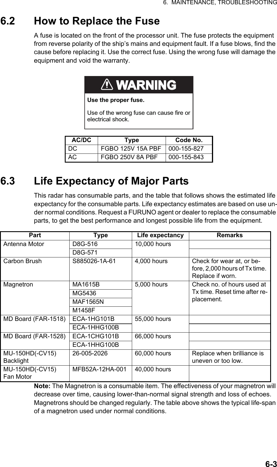
![6. MAINTENANCE, TROUBLESHOOTING6-46.4 Trackball MaintenanceIf the cursor skips or moves abnormally, clean the trackball using the procedure below.1. Turn the retaining ring counterclockwise 45° to unlock it.2. Remove the retaining ring and ball.3. Clean the ball with a soft, lint-free cloth, then blow carefully into the ball-cage to dislodge dust and lint.4. Look for a build-up of dirt on the metal rollers. If dirty, clean the rollers using a cotton swab moistened lightly with isopropyl-rubbing alcohol.5. Make sure that fluff from the swab is not left on the rollers.6. Replace the ball and retaining ring. Be sure the retaining ring is not inserted reversely.6.5 Easy TroubleshootingThis section provides troubleshooting procedures that the user can follow to restore normal operation. If you cannot restore normal operation, do not attempt to check inside any unit. Any repair work is best left to a qualified technician.Problem Possible cause RemedyKey beep inaudible. Key beep turned off. Adjust key beep level in the [OPERATION] menu, referring to section 1.10.Picture not updated or picture freeze. 30 seconds after the picture freezes, the buzzer sounds, the ALERT ACK key blinks and alarm signal is output.Video freeze. Turn the power off and on again to restore normal operation.Power is ON but nothing appears on monitor.Brilliance is too low. Adjust the brilliance, referring to section 1.4.Marks, indications and noise appear but no echo.Tx high voltage protection circuit has activated.Reset the power to restore normal operation.Range changed but radar picture does not change.Defective range key or video freeze up.Adjust the range with the control unit, or the [RANGE] box several times. If unsuccessful, replacement of keypad may be required. If that does not work try to turn the power off and on again to see if the problem might be video freeze up.Only two PI lines when six lines are wantedIncorrect setting of PI line intervalAdjust PI line interval, referring to paragraph 1.39.2. Also, the setting for number of PI lines to display may be inappropriate. Check the menu setting for number of PI lines, referring to paragraph 1.39.1.Retaining ring](https://usermanual.wiki/Furuno-USA/9ZWRTR101.User-Manual-Part-5/User-Guide-2768733-Page-43.png)
![6. MAINTENANCE, TROUBLESHOOTING6-56.6 Advanced-level TroubleshootingThis section describes how to cure hardware and software troubles that should be carried out by qualified service personnel.Note 1: This radar equipment contains complex modules in which fault diagnosis and repair down to component level are not practicable by users.Note 2: When replacement of the SPU board is necessary, the previous settings can be transferred to new SPU board as follows:• Save your settings to a SD card, referring to section section 1.51.• After replacing the SPU board, load the entire contents of the SD card to the radar, referring to section section 1.51 for the procedure.Range rings are not displayed Range rings turned off Try turning on the range rings with [RANGE RING] in the [NAVTOOL] menu. If they do not appear, their brilliance may be too low. Adjust their bril-liance in the [BRILL] menu.Tracked target not tracked cor-rectlyPoor definition of targets in sea clutterAdjust A/C SEA and A/C RAIN referring to section 1.19 and section 1.20.Tuning adjusted but poor sensi-tivitySecond trace echo rejector on or dirt on radiator face• Disable the second trace echo rejector, referring to section 1.28.• Clean the radiator face.Problem Possible cause RemedyPower turned on but radar does not operate at all1) Blown fuse.2) Mains voltage/polarity.3) Power supply board.1) Replace blown fuse.2) Correct wiring and input voltage.3) Replace power supply board.Brilliance adjusted but no pictureSPU board Replace SPU board.Antenna not rotating 1) Antenna drive mecha-nism2) Defective antenna drive motor relay1) Replace antenna drive mechanism.2) Press relay reset button.Data and marks not displayed in Transmit statusSPU board Replace SPU board.Adjust GAIN with A/C SEA set at minimum. Marks and indications appear but no noise or echo.1) IF amplifier2) Signal cable between an-tenna and processor unit3) Video amplifier board1) Replace IF amplifier.2) Check continuity and isolation of coax-ial cable.Note: Disconnect the plug and lugs at both ends of coaxial cable before checking it by ohmmeter.3) Check video coax line for secure con-nection. If connection is good, replace SPU board.Problem Possible cause Remedy](https://usermanual.wiki/Furuno-USA/9ZWRTR101.User-Manual-Part-5/User-Guide-2768733-Page-44.png)
![6. MAINTENANCE, TROUBLESHOOTING6-6Marks, indications and noise appear but no echo (Transmission leak representing own ship position is absent)1) TX high voltage protec-tion circuit has activated.2) Magnetron3) Modulator board4) SPU board1) Reset power to restore normal opera-tion.2) Check magnetron current.Replace magnetron.3) Replace modulator board.4) Replace SPU board.Picture not updated or picture freeze-up1) Bearing signal generator board (in antenna unit)2) SPU board3) Video freeze-up1) Check the connection of signal cables.2) Replace SPU board.3) Turn off and on the radar.Incorrect orientation of picture1) SPU board2) Gyro interface1) The message "HDG SIG MISSING" appears when the heading pulse is not received during transmitting.2) Replace the gyro interface.Cannot operate radar from on-screen boxesSPU Board Replace SPU Board.Radar is properly tuned but poor sensitivity1) Deteriorated magnetron2) Detuned MIC3) Dirt on radiator face4) Water ingress to the waveguide or other feeder line5) Second trace echo rejec-tion is ON1) With the radar transmitting on 48 nm range, check magnetron current. If current is below normal, magnetron may be defective. Replace it.2) Check MIC detecting current. If it is be-low normal value, MIC may have be-come detuned. MIC must be tuned.3) Clean the radiator surface.4) Remove water from the feeder line.5) Disable the second-trace echo rejector referring to section 1.28.Range changed but ra-dar picture not chang-ing1) Defective range key2) SPU board3) Video freeze up1) Adjust the range with the control unit, or the [RANGE] box several times. If unsuccessful, replacement of keypad may be required.2) Replace SPU board.3) Turn off and on radar.Interference rejector is inoperative (interfer-ence rejection level not displayed)SPU board Replace SPU board.Echo stretch is ineffec-tive (neither ES1, ES2 nor ES3 is displayed)SPU board Replace SPU board.Range rings are not displayed1) Adjust the brilliance of range rings on the BRILL menu to see if intensity is increased2) SPU board1) Replace associated circuit board if unsuccessful.2) Replace SPU board.Poor discrimination in rangeSea clutter control not func-tioning properlyImproper setting of A/C SEA. If A/C SEA is seen only at very close range, suspect in-accurate frequency of reference oscillator.Problem Possible cause Remedy](https://usermanual.wiki/Furuno-USA/9ZWRTR101.User-Manual-Part-5/User-Guide-2768733-Page-45.png)
![6. MAINTENANCE, TROUBLESHOOTING6-76.7 DiagnosticsA diagnostic test program is provided to test major circuit boards in the control unit, processor unit and card I/F unit. Note that the normal radar picture is lost during this test.Proceed as follows to execute the diagnostic test:1. Open the [MAIN MENU].2. Select [INITIAL SETTING], then press the left button.3. Select [TEST], then press the left button.4. Select [SELF TEST], then press the left button.5. To stop the test at any time, press the key.In a few moments the results of the test are displayed and the buzzer sounds continuously. The ROMs and RAMs of the SPU, RFC, Control Unit, Trackball Control Unit and SD CARD readers are checked for proper operation. "OK" appears for normal operation. If "NG" (No Good) appears, corresponding components may be defective. Consult your dealer. In the middle of the display the rpm of the antenna unit and various voltages are displayed.True motion orientation not working correctly1) Incorrect menu setting.2) Speed entry incorrect3) TM display inaccurate1) Referring to section 1.29, select TM orientation mode.2) Enter correct own ship speed referring to section 1.12.3) Make sure that speed and compass in-puts are accurate.Target not tracked cor-rectlyPoor definition of targets in sea clutterAdjust A/C SEA and A/C RAIN referring to section 1.19 and section 1.20.Buttons on trackball module operated but no responseTrackball module Replace trackball module.Picture is not updated with each sweep.1) Slots in rotating disc in antenna unit2) Motor brushes1) Remove foreign material (carbon, grease, etc.) from slots.2) Replace motor brushes if they are shorter than 6 - 7 mm.Problem Possible cause Remedy](https://usermanual.wiki/Furuno-USA/9ZWRTR101.User-Manual-Part-5/User-Guide-2768733-Page-46.png)
![6. MAINTENANCE, TROUBLESHOOTING6-86.8 Fallback ArrangementsIf the top priority sensor (for example GPS1) cannot be used, this equipment automatically uses the second priority sensor (for example, GPS2) when multiple sensors (GPS1 and GPS2 for example) are installed. When there is no fallback sensor available, each function is limited as follows:Sensor Function limitationsHeading sensor• The [HDG] indication reads "***.*°"• The orientation mode is automatically set to [HEAD-UP].• TT, AIS, radar map and echo averaging are disabled.Speed sensorWhen [LOG(WT)] is selected:• The sensor used is automatically switched in the following priority order: GPS(BT) > LOG(BT).• The SPD indication reads "***.* kn" when both GPS(BT) and LOG(BT) cannot be used.When [LOG(BT)] is selected:• The sensor used is automatically switched in the following priority order: GPS(BT) > LOG(WT).• The SPD indication reads "***.* kn" when both GPS(BT) and LOG(WT) cannot be used.When [GPS(BT)] is selected:• The sensor used is automatically switched in the following priority order: LOG(BT) > LOG(WT).• The SPD indication reads "***.* kn" when both LOG(BT) and LOG(WT) cannot be used.COG/SOG sensor• When the GPS sensor cannot be used, the values of COG and SOG are calculated from HDG and LOG(BT).• Additionally when the heading sensor cannot be used, the values of SOG is calculated from LOG(BT). The COG indication reads "***.*°".Position sensor• The POSN indication reads all asterisks.• AIS and radar map are disabled.](https://usermanual.wiki/Furuno-USA/9ZWRTR101.User-Manual-Part-5/User-Guide-2768733-Page-47.png)
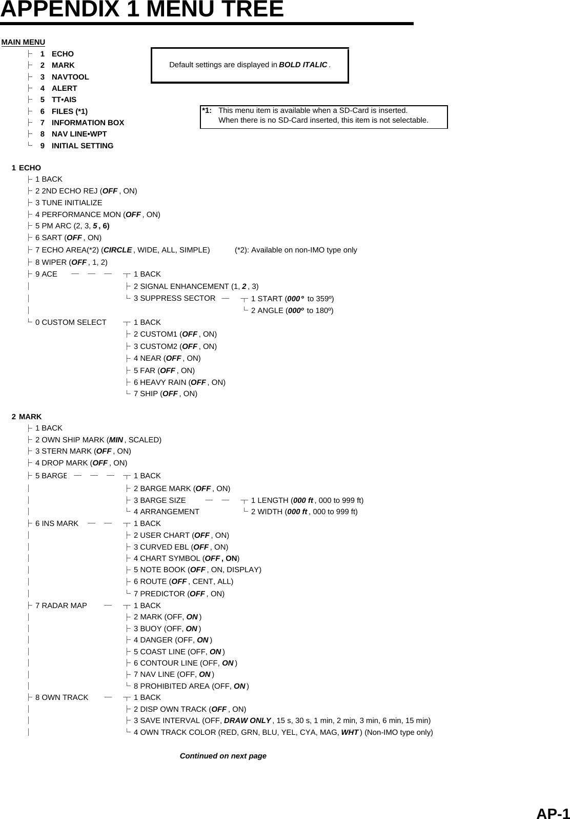
![APPENDIX 1 MENU TREE├9 DATA DELETE ┬1 BACK│├2 MARK ALL DELETE (YES, NO )│├3 WPT ALL DELETE (YES, NO )│└4 OWN TRACK DELETE(*2) (2POINTS, AREA )(*2) Non-IMO type only└0 GRID (OFF, ON )3 NAVTOOL├1 BACK├2 PI LINE──── ┬1 BACK│├2 PI LINE BEARING(*2) (REL , TRUE) (*2) Non-IMO type only│├3 SET ALL PI LINE (1, 2, 3, 6)│├4 PI LINE MODE (PARALLEL , PERPENDIC)│├5 RESET PI LINE│├6 TRUNC RANGE 1 (OFF , ON; 0.000 NM to 24.000 NM)│└7 TRUNC RANGE 2 (OFF , ON; 0.000 NM to 24.000 NM)├3 EBL•VRM•CURSOR(*1) ┬1 BACK (*1) IMO type only│├2 EBL OFFSET BASE (STAB GND , STAB HDG, STAB NORTH)│├3 VRM TTG (OFF , 1, 2, 1 and 2)│├4 VRM OFFSET (OFF , LINK EBL)│└5 EBL•CURSOR BEARING (REL , TRUE)├4 EBL•VRM(*2) ── ┬1 BACK (*2) Non-IMO type only│├2 EBL1 (REL , TRUE)│├3 EBL2 (REL , TRUE)│├4 VRM1 (REL , TRUE)│├5 VRM2 (REL , TRUE)│├6 EBL OFFSET BASE (STAB GND , STAB HDG, STAB NORTH)│├7 VRM TTG (OFF , 1, 2, 1 and 2)│├8 VRM OFFSET (OFF , LINK EBL)│└9 CURSOR ── ┬1 BACK│├2 CURSOR BEARING (REL , TRUE)│├3 CURSOR RANGE (NM , KM, SM)│└4 CURSOR SIZE (SMALL , LARGE)└5 RANGE RING (OFF, ON )4 ALERT├1 BACK├2 ALERT SOUND LEVEL (OFF, LOW, MID, HIGH )├3 ANCHOR WATCH (OFF , ON; 0.01 NM to 9.99 NM)├4 ARRIVAL WPT (OFF , ON; 0 to 999 m)├5 TARGET ALARM ─┬1 BACK│├2 ALR1 MODE (IN , OUT)]│├3 ALR2 MODE (IN , OUT)│└4 LEVEL (1, 2, 3, 4)└6 PRIMARY ALERT ─┬1 BACK└5TT•AIS├1 BACK├2 ACQUISITION ZONE ─┬1 BACK│├2 AZ STAB (STAB HDG , STAB NORTH)│├3 AZ POLYGON (OFF , STAB GND, STAB HDG, STAB NORTH)│└4 AZ/ALR SWITCH (ACQUISITION ZONE , TARGET ALARM ZONE)├3 TT•AIS SYMBOL── ┬1 BACK│├2 SYMBOL COLOR (GRN, BLU, CYA, MAG, WHT )│├3 ATON SYMBOL COLOR (GRN, BLU, CYA, MAG, WHT )│├4 AIS ROT TAG LIMIT (000.0 º/min to 720.0º/min)│├5 TT·AIS PAST POSN POINTS (5, 10)│└6 AIS SCALED SYMBOL (OFF , ON)├4 CPA AUTO ACTIVATE ┬1 BACK│├2 MAX RANGE (OFF , ON; 00 NM to 99 NM)│├3 MIN SHIP SPEED (OFF , ON; 1.0 kn to 9.9 kn)│└4 EXCEPT CLASS B (OFF , ON)Continued from previous page2 TT NEW TARGET, TT LOST, TT TARGET FULL(AUTO), TT TARGET FULL(MAN),AIS NEW TARGET, AIS LOST, XTE, ARRIVAL, DEPTH, ANCHOR WATCHContinued on next pageAP-2](https://usermanual.wiki/Furuno-USA/9ZWRTR101.User-Manual-Part-5/User-Guide-2768733-Page-49.png)
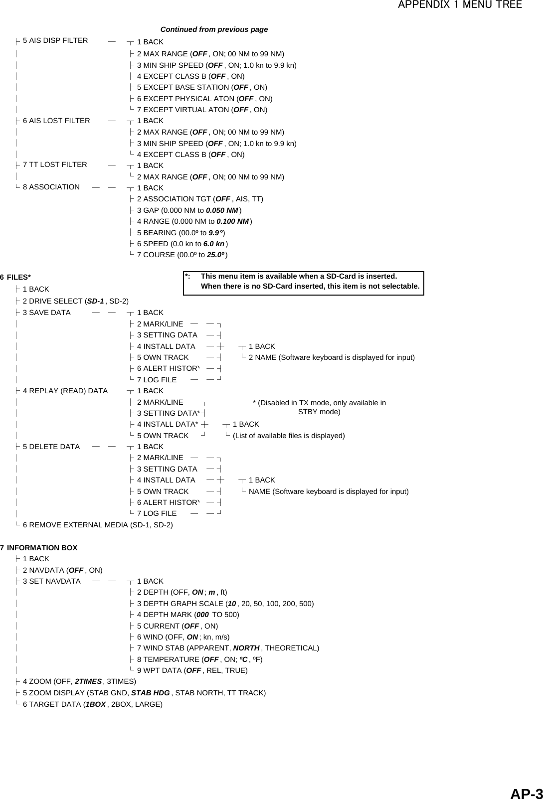
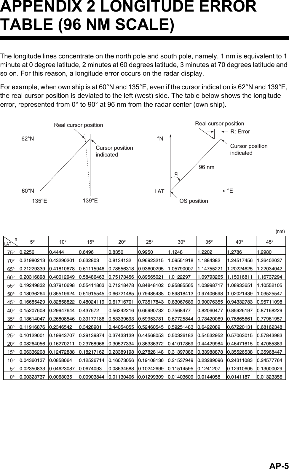
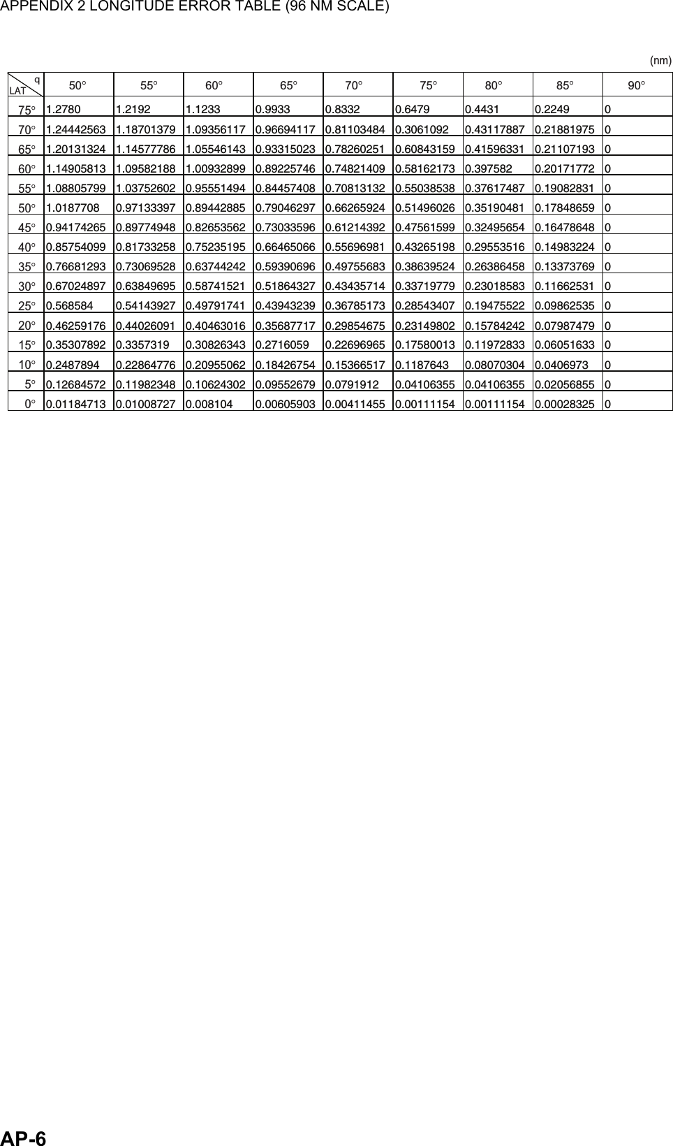
![AP-7APPENDIX 3 ALERT CODES, MESSAGES AND MEANINGSThis radar can output alerts in ALF format or ALR format. The output format is set at installation. A qualified FURUNO technician is required to change the output format.Alerts are displayed at the bottom right of the screen with the title of the alert and the alert code.The ALF format outputs a four or five-digit alert code and the ALR format outputs a three-digit code. The tables below show the alert ID, title, priority, category, meaning and the remedy for each alert.For ALF format alerts, the alert identifier (the first three digits of the alert code), is displayed on the alert list and the alert instance (the last one or two digits of the alert code), is transferred along with it's identifier to the connected Bridge Alert Management System. The table below shows the full code for ALF formats alerts, with the instance separated by a comma.ALF format alertsAlert ID Alert title Priority & Category Message and meaning190,1 TARGET CAPACITY CautionCat: AMessage: "TT TARGET 95%(AUTO)"Meaning: Automatically acquired target capacity has reached 95%.Remedy: Press the ALERT ACK key. Remove TT symbols manually.190,2 TARGET CAPACITY WarningCat: AMessage: "TT TARGET FULL(AUTO)"Meaning: Automatically acquired target capacity has reached 100%.Remedy: Press the ALERT ACK key. Remove TT symbols manually.190,3 TARGET CAPACITY CautionCat: AMessage: "TT TARGET 95%(MAN)"Meaning: Manually acquired target capacity has reached 95%.Remedy: Press the ALERT ACK key. Remove TT symbols manually.190,4 TARGET CAPACITY WarningCat: AMessage: "TT TARGET FULL(MAN)"Meaning: Manually acquired target capacity has reached 100%.Remedy: Press the ALERT ACK key. Remove TT symbols manually.190,5 TARGET CAPACITY CautionCat: AMessage: "AIS DISPLAY 95%"Meaning: AIS display capacity has reached 95% (285 targets).Remedy: Press the ALERT ACK key. Adjust [AIS DISP FILTER] settings to decrease the number of targets displayed.190,6 TARGET CAPACITY WarningCat: AMessage: "AIS DISPLAY FULL"Meaning: AIS display capacity has reached 100% (300 targets).Remedy: Press the ALERT ACK key. Adjust [AIS DISP FILTER] settings to decrease the number of targets displayed.190,8 TARGET CAPACITY CautionCat: AMessage: "AIS CAPACITY FULL"Meaning: AIS capacity has reached 100% (1000 targets).Remedy: Press the ALERT ACK key. Adjust [AIS DISP FILTER] settings to decrease the number of targets displayed.](https://usermanual.wiki/Furuno-USA/9ZWRTR101.User-Manual-Part-5/User-Guide-2768733-Page-54.png)
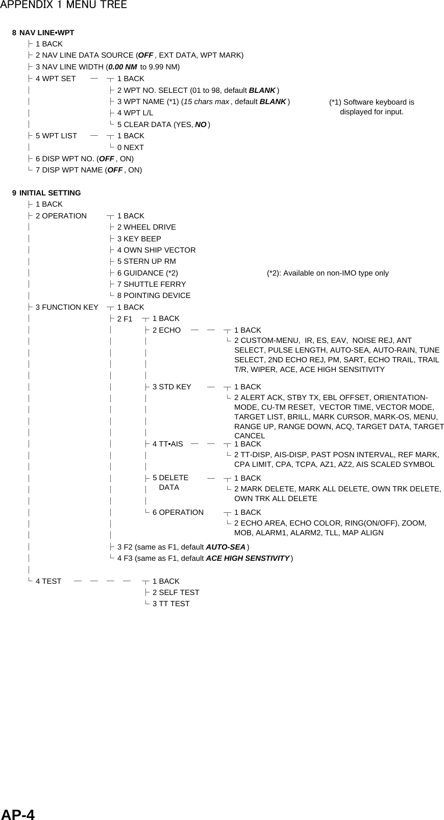
![APPENDIX 3 ALERT CODES, MESSAGES AND MEANINGSAP-8190,9 TARGET CAPACITY CautionCat: AMessage: "AIS ACTIVATE 95%"Meaning: Active AIS target capacity has reached 95% (38 targets).Remedy: Press the ALERT ACK key. Adjust [AIS DISP FILTER] settings to decrease the number of targets displayed.190,10 TARGET CAPACITY WarningCat: AMessage: "AIS ACTIVATE FULL"Meaning: Active AIS target capacity has reached 100% (40 targets).Remedy: Press the ALERT ACK key. Adjust [AIS DISP FILTER] settings to decrease the number of targets displayed.191,1 CPA/TCPA AlarmCat: AMessage: "TT COLLISION"Meaning: TT is within CPA/TCPA threshold, danger of collision. Remedy: Press the ALERT ACK key. Take evasive action if necessary. Adjust CPA/TCPA settings.191,2 CPA/TCPA AlarmCat: AMessage: "AIS COLLISION"Meaning: AIS target is within CPA/TCPA threshold, danger of collision.Remedy: Press the ALERT ACK key. Take evasive action if necessary. Adjust CPA/TCPA settings.192,1 NEW TARGET WarningCat: AMessage: "TT NEW TARGET"Meaning: A new TT target has entered the Acquisition Zone.Remedy: Press the ALERT ACK key. Confirm location of new target.192,2 NEW TARGET WarningCat: AMessage: "AIS NEW TARGET"Meaning: A new AIS target has entered the Acquisition Zone.Remedy: Press the ALERT ACK key. Confirm location of new target.193,1 LOST TARGET WarningCat: AMessage: "TT LOST"Meaning: TT target is lost.Remedy: Press the ALERT ACK key. Lost target indication (blinking in red) is removed.193,2 LOST TARGET WarningCat: AMessage: "REF TARGET LOST"Meaning: REF targets is lost.Remedy: Press the ALERT ACK key. Lost target indication (blinking in red) is removed.193,3 LOST TARGET WarningCat: AMessage: "AIS LOST"Meaning: AIS target is lost.Remedy: Press the ALERT ACK key. Lost target indication (blinking in red) is removed.194,1 SYSTEM ERROR WarningCat: BMessage: "HEADLINE"Meaning: Heading signal interrupted/lost.Remedy: Press the ALERT ACK key. Restore signal or rectify reason for signal loss.194,2 SYSTEM ERROR WarningCat: BMessage: "AZIMUTH"Meaning: Azimuth signal is interrupted/lost.Remedy: Press the ALERT ACK key. Restore signal or rectify reason for signal loss.194,3 SYSTEM ERROR WarningCat: BMessage: "TRIGGER"Meaning: Output trigger interrupted/lostRemedy: Press the ALERT ACK key. Restore signal or rectify reason for signal loss.194,4 SYSTEM ERROR WarningCat: BMessage: "VIDEO"Meaning: Video signal interrupted/lost.Remedy: Press the ALERT ACK key. Restore signal or rectify reason for signal loss.194,5 SYSTEM ERROR WarningCat: BMessage: "KEY"Meaning: Control unit signal interrupted/lost.Remedy: Press the ALERT ACK key. Restore signal or rectify reason for signal loss.Alert ID Alert title Priority & Category Message and meaning](https://usermanual.wiki/Furuno-USA/9ZWRTR101.User-Manual-Part-5/User-Guide-2768733-Page-55.png)
![APPENDIX 3 ALERT CODES, MESSAGES AND MEANINGSAP-9194,6 SYSTEM ERROR WarningCat: BMessage: "PM COMM ERROR"Meaning: PM communication error.Remedy: Press the ALERT ACK key. Restore signal or rectify reason for signal loss.194,7 SYSTEM ERROR WarningCat: BMessage: "TUNE ERROR"Meaning: TUNE error due to faulty settings or malfunction.Remedy: Press the ALERT ACK key. Restore signal or rectify reason for signal loss.485,1 DEPTH WarningCat: BMessage: "DEPTH"Meaning: Depth is below set threshold.Remedy: Press the ALERT ACK key. Confirm depth. Adjust [DEPTH] settings as required.495,1 ANCHOR WATCH WarningCat: BMessage: "ANCHOR WATCH"Meaning: Ship position outside set anchor watch zone.Remedy: Press the ALERT ACK key. Confirm Own Ship location and adjust as necessary.540,1 AIS MSG CautionCat: BMessage: "TRANSMIT ERROR"Meaning: Unable to transmit AIS binary message.Remedy: Press the ALERT ACK key. Check power to AIS unit.540,2 AIS MSG CautionCat: BMessage: "AIS TRANSMITTING"Meaning: Transmitting AIS message.Remedy: Press the ALERT ACK key. No other action required.560,1 ASSOCIATION CautionCat: BMessage: "ASSOCIATION"Meaning: One or more sets of associated targets is displayed.Remedy: Press the ALERT ACK key. Set [ASSOCIATION] to [OFF].601,1 SENSOR ERROR WarningCat: BMessage: "GYRO"Meaning: No heading information received from gyrocompass for five seconds.Remedy: Press the ALERT ACK key. Match the on-screen indication with the actual gyrocompass. The indication “HEADING SET” appears. Press the ALERT ACK key to erase the indication.601,2 SENSOR ERROR Warning/CautionCat: BMessage: "LOG(WT)"Meaning: No speed data received for five seconds when [LOG(WT)] is set as speed reference.Remedy: Press the ALERT ACK key. Check SDME sensor. Use a different sensor if necessary.601,3 SENSOR ERROR Warning/CautionCat: BMessage: "LOG(BT)"Meaning: No speed data received for thirty seconds when [LOG(BT)] is set as speed reference.Remedy: Press the ALERT ACK key. Check SDME sensor. Use a different sensor if necessary.601,4 SENSOR ERROR WarningCat: BMessage: "EPFS"Meaning: EPFS Error. No speed or position data received from EPFS device for thirty seconds.Remedy: Press the ALERT ACK key. Restore the signal. This indication cannot be erased if the position signal is missing. The indication is automatically removed when the signal is restored.601,5 SENSOR ERROR WarningCat: BMessage: "DATUM"Meaning: DTM sentence no received for thirty seconds or erroneous data received.Remedy: Press the ALERT ACK key. Use the WGS-84 datum.601,6 SENSOR ERROR WarningCat: BMessage: "UTC"Meaning: UTC error. No date or time data received for thirty seconds. No ZDA sentence input.Remedy: Press the ALERT ACK key. Restore the signal to remove this indication.Alert ID Alert title Priority & Category Message and meaning](https://usermanual.wiki/Furuno-USA/9ZWRTR101.User-Manual-Part-5/User-Guide-2768733-Page-56.png)