Furuno USA 9ZWRTR101 Transceiver for Radar model FAR-1518/1528 User Manual OME 36380 A
Furuno USA Inc Transceiver for Radar model FAR-1518/1528 OME 36380 A
Contents
- 1. Installation Manual Part 3
- 2. Installation Manual Part 1
- 3. Installation Manual Part 2
- 4. Installation Manual Part 4
- 5. Installation Manual Part 5
- 6. Installation Manual Part 6
- 7. User Manual Part 1
- 8. User Manual Part 2
- 9. User Manual Part 3
- 10. User Manual Part 4
- 11. User Manual Part 5
- 12. User Manual Part 6
User Manual Part 5
3. TARGET TRACKING (TT)
3-12
3.10.2 How to change the vector length (time)
The vector time provides an estimation of the target’s vector and can be adjusted as
follows:
Place the cursor on the vector time indication in the [Vector] box, then press the left
button. The vector time cycles through the following settings with each press of the
left button.
[6min] [10min] [20min] [30min] [45min] [60min] [30sec] [1min]
[3min] [5min] [6min]...
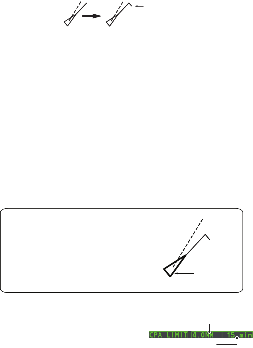
The vector tip shows an estimated position of the target after the selected vector time
elapses. It can be valuable to extend the vector length to evaluate the risk of collision
with any target.
3.11 Past Position Display
The past position display shows equally time-spaced dots marking the past positions
of any targets being tracked.
A new dot is added every minute (or at other preset time intervals) until the preset
number is reached. If a target changes its speed, the spacing will be uneven. If it
changes the course, its plotted course will not be a straight line.
Past position orientation, true or relative, is controlled with [TRAIL MODE] in the
[TRAIL] context menu. To adjust the trail orientation, see paragraph 1.36.1.
3.11.1 How to display past position points and select the past
position plotting interval
Place the cursor on the [PAST POSN] time indication in the [PAST POSN] box, then
press the left button. The past position points are displayed and their plotting interval
changes with each press of the left button, as shown below.
[OFF] [30sec] [1min] [2min] [3min] [6min] [OFF]...
3.11.2 How to select the number of past position points to be
displayed
1. Open the [MAIN MENU].
2. Select [TT•AIS], then press the ADJUST knob.
3. Select [TT•AIS SYMBOL], then press the ADJUST knob.
4. Select [TT•AIS PAST POSN POINTS], then press the ADJUST knob.
5. Select [5] or [10] as appropriate, then press the ADJUST knob.
6. Close the menu.
3. TARGET TRACKING (TT)
3-13
3.12 Set and Drift
Set, the direction in which a water current flows, can be manually entered in
0.1-degree steps. Drift, also known as “Rate”, or the speed of the current, can also be
entered manually in 0.1-knot steps.
When course through water and speed through water are available, activate set and
drift to get course over ground and speed over ground.
Set and drift corrections are beneficial for increasing the accuracy of vectors and tar-
get data. Refer to the tide table on board the ship for setting information. These values
are applied to all targets. If stationary targets have vectors, set and drift values should
be adjusted until they lose vectors.
To enter set and drift do the following:
1. Select the [SPD] menu box, then press the right button. The [SHIP SPEED
MENU] is displayed.
2. Select [SET DRIFT], then press the ADJUST knob.
3. Select [ON], then press the ADJUST knob. The setting can now be adjusted and
[SET] is selected.
4. Rotate the ADJUST knob to select the appropriate setting (Setting range: 000.0°
to 359.9°), then press the ADJUST knob. The [DRIFT] setting is now selected.
5. Rotate the ADJUST knob to select the appropriate setting (Setting range: 00.0kn
to 19.9kn), then press the ADJUST knob.
6. Close the menu.
Note 1: Set and drift are available when using manually input speed, speed through
the water. The speed source is shown as "WTC" (Water Tracking Count).
Note 2: Set and drift should be checked periodically for correctness.
Note 3: When speed data input from the position sensor is valid, set and drift is not
adjustable.
3. TARGET TRACKING (TT)
3-14
3.13 Collision Alarm (CPA, TCPA)
This radar calculates CPA and TCPA by using own ship and relative target positions.
The TT continuously monitors the
predicted range at the Closest Point of
Approach (CPA) and predicted time to
CPA (TCPA) of each TT. When the
predicted CPA of any TT becomes
smaller than a preset CPA range and its
predicted TCPA less than a preset
TCPA limit, the audio alarm sounds and
TT COLLISION appears (in red) in the
Alert Box. In addition, the symbol of the
offending TT is red and flashes together
with its vector.
This feature, when used correctly, helps prevent the risk of collision by alerting you to
threatening targets. It is important that GAIN, A/C SEA, A/C RAIN and other radar
controls are properly adjusted.
CPA and TCPA ranges must be set up properly taking into consideration the size, ton-
nage, speed, turning performance and other characteristics of own ship.
The reference point for CPA and TCPA calculation can be selected from antenna
position or conning position. For further details, see section 1.47.
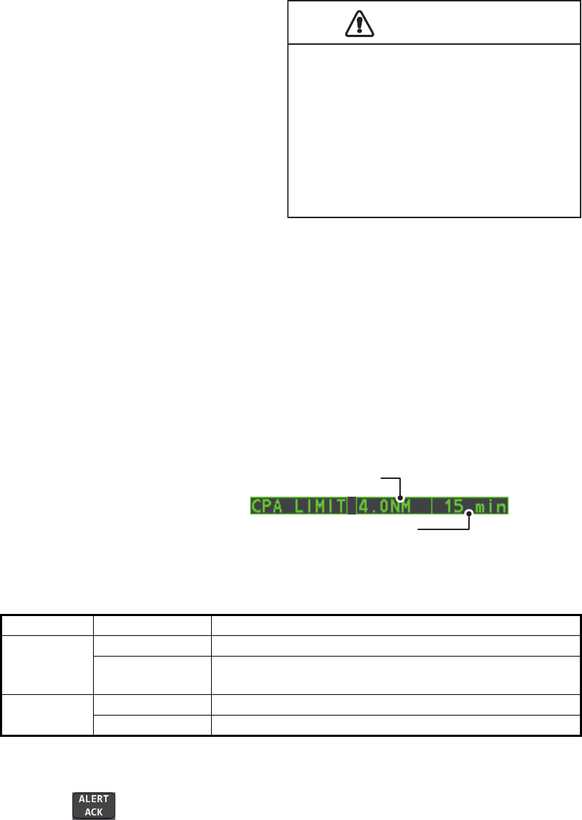
3.13.1 How to set the CPA and TCPA ranges
CPA and TCPA ranges can be
adjusted from the appropriate
indication in the [TT] box.
1. Place the cursor on the indication you wish to adjust.
2. Press the left button, or rotate the ADJUST knob, to adjust the settings as
required. The settings options are outlined in the table below.
3.13.2 How to acknowledge the TT collision alarm
Press the key on the control unit, or select the [ALERT] box with the Touchpad
then press the left button to acknowledge the alarm and silence the buzzer. The alert
"TT COLLISION" and the flashing of the plotting symbol and vector remain in the Alert
Box until the dangerous situation is gone or you intentionally terminate tracking of the
target.
Note that when the TT COLLISION alarm is generated the AIS display is automatically
turned on.
Indication Key Settings options
CPA Left button 0.5, 1, 1.5, 2, 3, 4, 5, 6 (nm)
ADJUST knob 0.1-20 (nm), 0-10 nm in 0.1 nm increments, 10 nm
increments thereafter
TCPA Left button 1, 2, 3, 4, 5, 6, 12, 15 (minutes)
ADJUST knob 1-60 minutes, 1-minute increments
CAUTION
CPA/TCPA Alarm
The CPA and TCPA alarm feature should
never be relied upon as the sole means for
detecting the risk of collision.The navigator
is not relieved of the responsibility to keep
visual lookout for avoiding collisions,
whether or not the radar or other plotting
aid is in use.
CPA setting
TCPA setting
3. TARGET TRACKING (TT)
3-15
3.14 Acquisition Zone
The acquisition zone functions both to alert you targets in a specific area and acts as
an automatic acquisition area when automatic target acquisition is active. Any targets
entering the zone will be automatically acquired.
When a target enters an acquisition zone, the buzzer sounds and the indication "TT
NEW TARGET" (or "AIS NEW TARGET") appears (in yellow-orange) in the Alert Box.
The symbol of the offending target is red and flashing. Further, the AIS display is
automatically turned on if it is off.
There are two types of acquisition zones available, arc and polygon, however, AZ1
can only be set as an arc.
Note: The [AZ1] and [AZ2] boxes are not displayed when the setting for
[AZ/ALR SELECT] in the [TT•AIS] menu is set to [TARGET ALARM ZONE].
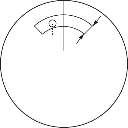
3.14.1 How to activate the first acquisition zone (AZ1)
The No. 1 acquisition zone is available between 3 and 6 nm The TT/AIS acquisition
zone’s lines are white and dashed so as to distinguish them from the radar target
alarm.
The procedure below shows how to set AZ1, using the example at the bottom of the
page.
1. Place the cursor on the [AZ] indication at the bottom-right of the screen.
2. Press the left button to cycle through the settings and select [SET].
3. Place the cursor on the acquisition zone starting point (“A” in the figure below),
then press the left button.
4. Place the cursor on the acquisition zone end point (“B” in the figure below), then
press the left button.
5. Press the right button to complete the acquisition zone set up.
0.5-1 nm
Target in acquision zone is
red and flashing.
A
B

3. TARGET TRACKING (TT)
3-16
3.14.2 How to set a polygon acquisition zone (AZ2)
The No. 2 acquisition zone can be set anywhere when the No. 1 zone is already in
use. Polygon zones must have at least three points.
To set a polygon shaped acquisition zone:
1. Place the cursor on the [AZ] indication at the bottom-right of the screen.
2. Press the left button to cycle through the settings and select [SET].
3. Place the cursor on the acquisition zone starting point, then press the left button.
4. Place the cursor on the second point, then press the left
button.
5. Repeat step 4 as required to set the remaining points of the polygon zone.
6. Press the right button to complete the acquisition zone set up.
Notes on acquisition zones
• If you wish to create an acquisition zone having a 360-degree coverage around own
ship, set point B in almost the same direction (approx. ±3°) as point A, then press
the left button.
• The default acquisition zone is fan shaped. It can also be a polygon having 3-10
points.
• If both acquisition zones are displayed, a maximum of four polygon points are
shown.
• TT and AIS are automatically set to TT=AUTO and AIS=DISP, respectively, when
an AZ is activated in the following conditions:
3.14.3 How to sleep/deactivate an acquisition zone
1. Select the appropriate [AZ] box.
2. Sleep, or deactivate, the acquisition zone, as explained below:
Sleeping the acquisition zone
Press the left button several times until the indication shows "SLEEP".
Deactivating the acquisition zone
Press and hold the left button until the AZ box becomes blank.
3.14.4 How to acknowledge the acquisition zone alert
Press the key on the control unit, or select the [ALERT] box with the Touchpad
then press the left button to acknowledge the alarm and silence the buzzer.
TT : TT=OFF or TT=MANUAL 50
AIS : AIS FUNC=OFF or AIS DISP=OFF

3. TARGET TRACKING (TT)
3-17
3.14.5 How to change the acquisition zone reference
The acquisition zone can be referenced to heading or North using the following
procedure:
1. Open the [MAIN MENU].
2. Select [TT•AIS], then press the ADJUST knob.
3. Select [ACQUISITION ZONE], then press the ADJUST knob.
4. Select [AZ STAB], then press the ADJUST knob.
5. Select [STAB HDG] to reference heading, or [STAB NORTH] to reference North.
6. Close the menu.
3.14.6 How to set acquisition zone shape and stabilization
The shape of the No. 2 acquisition zone can be a sector or a polygon having up to 10
points. (The shape of the No.1 acquisition zone is always a sector.)
1. Open the [MAIN MENU].
2. Select [TT•AIS], then press the ADJUST knob.
3. Select [ACQUISITION ZONE], then press the ADJUST knob.
4. Select [AZ POLYGON], then press the ADJUST knob.
5. Select the appropriate setting, then press the ADJUST knob.
6. Close the menu.
Setting Description
[OFF] Acquisition zone is a sector; number of points is limited to four.
Stabilized against land.
[STAB GND] Polygon having 3-10 points. Stabilized against ground.
[STAB HDG] Polygon having 3-10 points. Stabilized against heading.
[STAB NORTH] Polygon having 3-10 points. Stabilized against North.
3. TARGET TRACKING (TT)
3-18
3.15 TT System Messages
There are four main reasons the TT may trigger the audio and visual alerts:
• Collision alarm
• Acquisition zone alert
• Lost target alert
• Target capacity
To acknowledge the alert, press the key on the control unit, or select the
[ALERT] box with the Touchpad then press the left button to acknowledge the alert
and silence the buzzer.
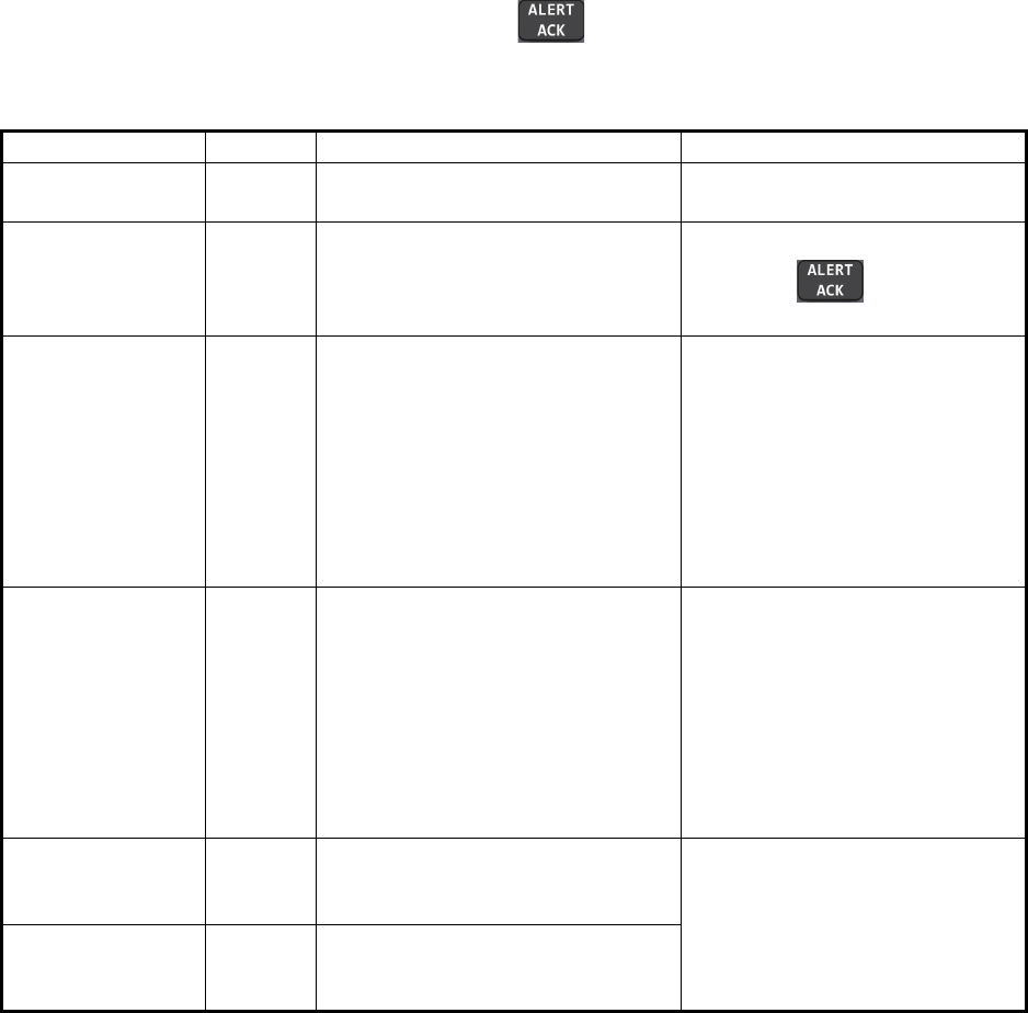
Alert message Priority Meaning Action required
TT COLLISION Alarm A tracked target is on collision
course with your vessel.
Take evasive action or
terminate tracking of TT.
TT NEW
TARGET
Warning Tracked target has entered an
acquisition zone. The tracked
target's symbol is red and
flashing.
Confirm the tracked target, then
press the key.
TT LOST Warning When the system detects a loss of
a tracked target, the lost tracked
target symbol appears in red and
flashes. At the same time, an
audio alert is produced for one
second. The lost target mark
disappears from the screen after
the lost target alert is
acknowledged.
Confirm the lost target,
re-acquire if necessary.
REF TARGET
LOST
Warning When the system detects a loss of
a reference target, the target
symbol turns red and flashes. At
the same time, an audio alert is
produced for one second. The
reference target mark disappears
from the screen after the
reference target alarm is
acknowledged.
To continue using a referenced
target for speed input, select
another tracked target.
TT TARGET
FULL (AUTO) or
(MAN)
Warning Appears when capacity for
automatically (manually) acquired
targets is full.
To continue acquiring targets,
cancel tracking for unnecessary
targets.
TT TARGET 95%
(AUTO) or (MAN)
Caution Appears when capacity for
automatically (manually) tracked
targets is 95% full.
3. TARGET TRACKING (TT)
3-19
3.16 TT Simulation Mode
You can simulate the risk of a collision by using the TT simulation mode. The test can
be terminated at any time by pressing the key.
1. Open the [MAIN MENU].
2. Select [INTIAL SETTING], then press the ADJUST knob.
3. Select [TEST], then press the ADJUST knob.
4. Select [TT TEST], then press the ADJUST knob.
The normal operation is suspended then three simulated targets appear on the dis-
play.
The indication "S" appears at the bottom of the effective display area during the sim-
ulation mode. The simulation may be terminated any time by going to the STBY mode.
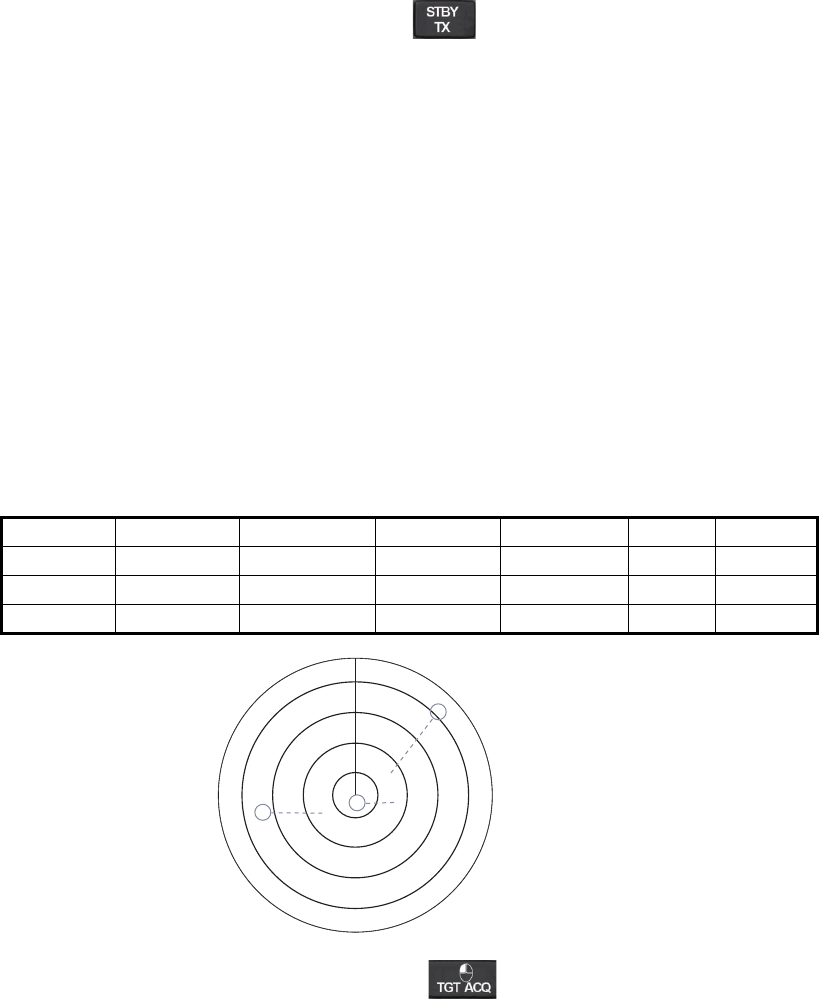
Three simulated targets move as the following table. The simulated target is automat-
ically generated with the relative movement in the following table based on own ship's
movement at the start of simulation mode.
Note: If own ship moves after the start of simulation mode, the movement of the sim-
ulated target is not matched with the values in the following table.
Place the cursor on a target, then press the key to display the target data.
Acquire the simulated targets after the TT simulation mode is performed. The tracking
state changes from unstable to stable and the vector appears. You can simulate the
movement of each function with changing true/relative vector, stabilization through the
water/over the ground, range or length of vector.
Repeat the check for all targets.
Range (R) Bearing (R) Speed (R) Course (R) CPA TCPA
Target 01 9.5 NM 270.0° 20.0 kn 90.0° 0.0 NM 28.5 min
Target 02 1.1 NM 333.0° 10.2 kn 90.2° 1.0 NM 2.9 min
Target 03 9.3 NM 45.0° 19.9 kn 225.1° 0.0 NM 28.0 min
S
01
03
02

3. TARGET TRACKING (TT)
3-20
3.17 Criteria for Tracking Target Selection
The FURUNO TT video processor detects targets in midst of noise and discriminates
radar echoes on the basis of their size. Target whose echo measurements are greater
than those of the largest ship in range or tangential extent are usually land and are
displayed only as normal radar video. All smaller ship-sized echoes that are less than
this dimension, are further analyzed and regarded as ships and displayed as small
circles superimposed over the video echo.
When a target is first displayed, it is shown as having zero true speed but develops a
course vector as more information is collected. In accordance with the International
Marine Organization Automatic Radar Plotting Aid (IMO TT) requirements, an
indication of the motion trend should be available within 20 scans of antenna and full
vector accuracy within 60 scans. The FURUNO TTs comply with these requirements.
Acquisition and tracking criteria
A target which is hit by five consecutive radar pulses, is detected as a radar echo.
Manual acquisition is done by designating a detected echo with the trackball.Automat-
ic acquisition is done in the acquisition areas when a target is detected 5-7 times con-
tinuously depending upon the congestion. Tracking is achieved the target is clearly
distinguishable on the display for 5 out of 10 consecutive scans, whether
acquired automatically or manually. Required tracking facilities are available within
0.1-32 nm on range scales including 3, 6, 12 nm, full plotting information is available
within one scan when the range scale has been changed.
Targets not detected in five consecutive scans become “lost targets”.
Quantization
The entire picture is converted to a digital from called “Quantized Video”. A sweep
range is divided into small segments and each range element is”1” if there is radar
echo return above a threshold level, or “0” if there is no return.
The digital radar signal is then analyzed by a ship-sized echo discriminator. As the
antenna scans, if there are five consecutive radar pulses with 1’s indicating an echo
presence at the exact same range, a target “start” is initiated. Since receiver noise is
random, it is not three-bang correlated, and it is filtered out and not classified as an
echo.
The same is true of radar interference. Electronic circuits track both the closet and
most distant edges of the echo. At the end of the scanning of the echo, the
discriminator indicates the measured maximum range extent and total angular extent
subtended by the echo. If the echo is larger than a ship-sized echo in range extent
and/or angular width, adjusted as a function of range, it is declared to be a coastline
and the closet edge is put into memory as a map of the area.
This land outline is used to inhibit further acquisition and tracking of ship-sized echoes
beyond the closest coast outline. Five consecutive scans of coastal outline are
retained in memory to allow for signal variation. All smaller echoes are declared to be
ship sized and the middle of the leading edge is used to provide precise range and
bearing coordinates of each echo on every scan. This range/bearing data is matched
to previous data and analyzed from scan-to-scan for consistency. When it is
determined to be as consistent as a real target, automatic acquisition occurs and
tracking is initiated. Continued tracking and subsequent calculation develop the
relative course and speed of the target.

3. TARGET TRACKING (TT)
3-21
The true course and speed of own ship are computed from own ship's gyro and speed
inputs, and the resulting course and speed of each tracked target is easily computed
by vector summing of the relative motion with own ship’s course and speed. The
resulting true or relative vector is displayed for each of the tracked targets. This
process is updated continually for each target on every scan of the radar.
Qualitative description of tracking error
The FURUNO TT's accuracy complies with or exceed IMO standards.
Own ship maneuvers
For slow turns there is no effect. For very high turning rates (greater than 150°/minute,
depending on gyro), there is some influence on all tracked targets that lasts for a
minute or two then all tracked targets revert to full accuracy.
Other ship maneuvers
Target ship courses, lag 15 to 30 seconds at high relative speed, or 3 to 6 seconds at
low (near 0) relative speed. It is less accurate during a turn due to lag, but accuracy
recovers quickly.
3.18 Factors Affecting TT Functions
Low gain
Insufficient or low radar receiver gain will result in some targets not being acquired at
long distance. TT display will be missing on one or more targets that could only be vis-
ible if the radar sensitivity control (GAIN control) were increased.
The setting of the correct radar receiver gain is not critical but the target should be on
the radar PPI and be clearly visible and well defined.
Manual acquisition is done if a target is positively displayed more than once.
Automatic acquisition is done when the target is detected 5-7 times continuously.
Tracking is achieved when the target is detected five times (not necessarily
continuously) out of 10 scans. If not detected six times out of 10 scans, the target will
become a “lost target”. The TT will acquire a radar echo that is present once in every
six antenna scans and continue tracking if 1 in 10.
Sea returns
If the radar anti-clutter control is adjusted properly, there is no serious effect because
distant wave clutter, not eliminated by this control, is filtered out by more than one
bang correlation and scan-to-scan matching of data.
Rain and snow
Clutter can be acquired and tracked as targets. Adjust the A/C RAIN control. If it is
heavy rain, switch to S-band if provided, or switch on the interference rejector on the
radar. If heavy clutter still exists, switch to manual acquisition. Accuracy can be
affected.
Low clouds
Usually no affect. If necessary, adjust the A/C RAIN.

3. TARGET TRACKING (TT)
3-22
Non-synchronous emissions
No effect.
Second trace echoes
When the radar beam is super refracted, strong echoes may be received at such long
ranges that they appear on a different timebase sweep than the transmitted pulse.
This gives an incorrect range indication. Second and third trace echoes can be tracked
if they are consistent enough to meet acquisition and tracking criteria but target course
and speed data will be in error.
Blind and shadow sectors
Radar shadow or blind areas caused by obstructions aboard ship, for example, fun-
nels and masts, in the path of the radar beam can result in reduction of radar beam
intensity in that particular direction. This may eliminate the detection of some targets.
The TT system will lose track of targets shortly after they are lost on the radar picture
and if they remain in a blind zone. These targets will however be acquired and tracked
when they pass out of the blind zone and again present normal radar echo. The an-
gular width and bearing of any shadow sector should be determined for their influence
on the radar. In certain cases false echoes in the shadow sector cause the TT system
to acquire, track, and vector them. Shadow sectors should be avoided.
Indirect echoes
A target at close range is usually picked up directly, but it can also be received as
reflection from a large, flat surface. This will result in the radar presenting two or more
echoes on the display, each at a different range. The TT can acquire and track the
false echo if it is detected by five consecutive scans. Reduction in radar gain can
eliminate the multiple echoing but care should be taken as range detection also will be
reduced.
Radar interference
If interference is extreme due to another radar operating at close range, spiral “dotting”
and/or false targets may appear momentarily. The interference rejector can clear the
display.
To receive radar beacon or SART signals, turn on [SART] in the [ECHO] menu.

4-1
4. AIS OPERATION
An AIS transponder can be connected to this radar to overlay AIS targets on the radar
display. The radar can store up to 1,000 AIS targets in its storage buffer. When this
buffer becomes full of AIS targets, the Alert 190 "TARGET CAPACITY (AIS
CAPACITY FULL)" is generated to alert you to full storage buffer. The storage buffer
contains automatic dead reckoning for all AIS targets, which is based on reported
Speed Over the Ground (SOG), Course Over the Ground (COG), Rate Of Turn (ROT)
and heading. The storage buffer also contains calculation of range, bearing, CPA,
TCPA, etc. The CPA and TCPA limits set for dangerous targets are common for TT
and AIS targets.
This radar can activate 40 AIS targets. The Alert 190 "TARGET CAPACITY (AIS
CAPACITY FULL)" is generated when 40 AIS targets are activated.
This radar can display a maximum of 300 AIS targets. The Alert 190 "TARGET
CAPACITY (AIS CAPACITY FULL)" is generated when 300 AIS targets, which
includes both activated and sleeping targets, are displayed.
The frequency for update of AIS transponder-sent data depends on speed and course
of tracked AIS target. The table below shows the IMO standardized reporting rates for
the AIS transponder. Based on the table below, the radar defines which AIS targets
are in tracking or lost. When you acknowledge a lost target alert, the corresponding
AIS symbol will be removed from the display.
An AIS transponder “sees” all ships fitted with an AIS transponder belonging to either
a Class A or Class B AIS. Additionally, the AIS transponder receives messages from
ships and non-ships (AIS SAR aircraft, AIS aid to navigation, AIS base station, and
AIS search and rescue transmitter).
Type of Ship
IMO
nominal
reporting
interval
Lost target
indication
(reporting
interval >)
Class A: Navigation status is “anchor” or “not under
command” or “moored” or “aground”, and SOG 3kn
3 min 10 min
Class A: Navigation status is “anchor” or “not under
command” or “moored” or “aground”, and SOG > 3kn
10 s 50 s
Class A: 0kn SOG < 14kn 10 s 50 s
Class A: 14kn SOG 23kn 6 s 30 s
Class A: SOG > 23kn 2 s 10 s
Class B: “CS” SOG < 2kn 3 min 10 min
Class B: “CS” SOG 2kn 30 s 150 s
Class B: “SO” 0 kn SOG < 2kn 3 min 10 min
Class B: “SO” 2 kn SOG < 14kn 30 s 150 s
Class B: “SO” 14 kn SOG 23kn 15 s 75 s
Class B: “SO” SOG > 23kn 5 s 25 s
Class A and Class B: no SOG available N/A 10 min
AIS SAR aircraft 10 s 50 s
AIS aid to navigation 3 min 10 min
AIS base station 10 s 50 s
AIS search and rescue transponder N/A 10 min
4. AIS OPERATION
4-2
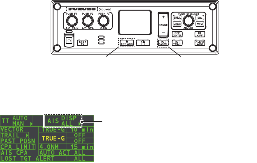
4.1 Controls for AIS
• TGT ACQ: Displays the selected target’s data.
• TGT CANCEL: Sleeps the cursor-selected target.
These functions, along with other AIS functions, can also be accessed from the
[CURSOR] menu (See section 1.7).
There can be several hundreds or several thousands of AIS targets, and of those only
a few will be significant for your ship. To remove unnecessary AIS targets from the
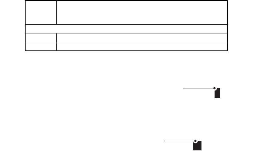
radar display, the feature “active and sleeping AIS targets” is available. Initially any new
AIS target received by an AIS transponder is not active (=“sleeping”). Such sleeping
targets are shown with a small triangle. The operator can pick any AIS target and
change it from sleeping to active. Active AIS targets are shown with a large triangle with
speed vector, headline, ROT indicator, etc. Further, the operator can pick active AIS
targets and change their status to sleeping.
An indication of AIS target activated capacity limit is given well before it is reached.
When 95% of 40 targets are activated, the Alert 190 "TARGET CAPACITY (AIS
ACITVATE 95%)" appears. When 40 targets are activated, the Alert 190 "TARGET
CAPACITY (AIS ACTIVATE FULL)" appears.
An indication of AIS target display capacity limit is given well before it is reached. When
95% of 300 targets are displayed, the Alert 190 "TARGET CAPACITY (AIS ACTIVATE
95%)" appears. When 300 targets are displayed, the Alert 190 "TARGET CAPACITY
(AIS DISPLAY FULL)" appears.
An indication of AIS target processing capacity limit is given well before it is reached.
The Alert 190 "TARGET CAPACITY (AIS CAPACITY FULL)" appears when 1,000
targets are in the storage buffer.
This radar generates AIS-related alerts. These are Alert 191 "CPA/TCPA (AIS
COLLISION" and Alert 193 "LOST TARGET (AIS LOST)". Only active AIS targets
generate alerts. The operator can activate or sleep AIS target alerts as desired. The
feature “active and sleeping AIS targets” is very effective for focusing on only those
AIS targets that need supervision. This radar further eases the task of the operator
by automatically changing non-active targets to active targets, if their CPA and
TCPA are within a preset limit.
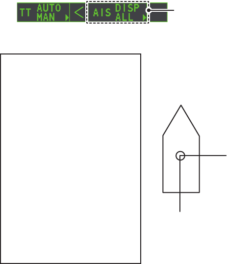
Displays AIS target data Cancel target
Select the AIS box, then press the left button to cycle
through AIS display modes.
DISP OFF: Hides AIS targets
DISP FILT: Displays a filtered selection of AIS targets
DISP ALL: Displays all AIS targets
FUNC OFF: Deactivates the AIS function
4. AIS OPERATION
4-3
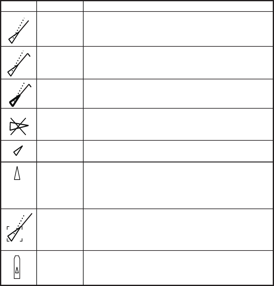
4.2 AIS Symbols and Their Meanings
When the AIS is active, AIS targets are marked with the appropriate AIS symbol, as
shown in the table below.
Note 1: The equipment continues to process AIS targets when the AIS feature is
deactivated. When the AIS is activated again, symbols are immediately displayed.
Note 2: AIS symbols are momentarily erased and the screen is redrawn after the
heading is changed in the HEAD UP mode.
Note 3: When no AIS data is received, the message "RECEIVE" appears in the Alert
Box. Check the AIS transponder.
Note 4: Physical and virtual AIS AtoN symbols that may appear are listed on the
following page.
Target with
neither a
reported
heading nor a
COG
Target selected
for data display
Scaled symbol
Sleeping target
Lost target
Dangerous
target
ROT higher
than preset
ROT
Activated
target
Symbol shape is based on antenna location, ship length and ship
width. Size changes depending on range from own ship.
Indicates the presence of a target equipped with AIS.
Color is selectable from menu.
Broken square is overlaid on target selected to display its data.
A, B or C shown to indicate data box location at right side of the
screen.
“X” overlaid on a lost target.
Red in color. Erased after acknowledged.
Displayed for turning ship.
All AIS symbols shown with thick line.
Color is selectable from menu.
Displayed when CPA/TCPA is within CPA/TCPA limit.
Red in color. Flashing until acknowledged.
A
A target with neither a reported heading nor COG is oriented
toward the top of the operational display area. The symbol is
shown with a solid line.
SYMBOL STATUS REMARKS
4. AIS OPERATION
4-4
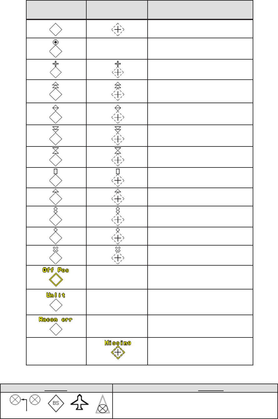
Note 5: Other AIS symbols that may appear are shown in the table below.
Note 6: The CPA and TCPA of SAR aircraft data are not available and are shown as
***.
Basic shape
RACON
Emergency wreck mark
North cardinal mark
East cardinal mark
South cardinal mark
West cardinal mark
Port hand mark
Starboard hand mark
Isolated danger
Safe water
Special mark
Off position (Displayed with yellow
line and yellow text)
Light fail or at reduced range
(Displayed with yellow text)
RACON error
(Displayed with yellow text)
Missing
(Displayed with yellow dashed
line and yellow text)
AIS Physical
AtoN Symbol
AIS Virtual
AtoN Symbol Meaning
shown in red when active
Other AIS symbols (from left, AIS SART (ACTIVE), AIS
SART (TEST), AIS Base station, AIS search and rescue
(SAR) Aircraft, AIS Search and Rescue (SAR) Vessel.)
Symbol Meaning

4. AIS OPERATION
4-5
4.3 How to Use the AIS Display Filter
If there are too many AIS targets on the screen you may wish to remove unnecessary
ones. You can remove sleeping targets A/B by distance from own ship, speed and
class. For example, you might want to remove slow moving targets, as they normally
do not require close monitoring.
1. Open the [MAIN MENU].
2. Select [TT•AIS], then press the left button.
3. Select [AIS DISP FILTER], then press the left button.
4. Referring to the table below, select the appropriate filtering type, then press the
left button.
5. Rotate the ADJUST knob to set the selected filter’s options, then press the
ADJUST knob.
6. Close the menu.
7. Place the cursor on the [AIS] box, then press the left button several times to dis-
play "DISP FILT" in the [AIS] box.
Note: This function is not available for an activated target.
4.4 How to Activate AIS Targets
When you convert a sleeping target to an activated target, that target’s course and
speed are shown with a vector. You can easily judge target movement by monitoring
the vector.
Sleeping targets within an acquisition zone are automatically changed to activated
targets and are colored red. See section 3.14 for how to use acquisition zones.
4.4.1 How to activate specific targets manually
Place the cursor on the target you wish to activate for AIS tracking, then press the left
button.
Filter type Definition
[MAX RANGE] Any sleeping AIS targets class A/B beyond the range set here will
not be shown.
[MIN SHIP SPEED] Any sleeping AIS targets class A/B slower than this setting will not
be shown.
[EXCEPT CLASS B] Select [ON] to remove sleeping AIS targets class B.
[EXCEPT BASE STATION] Select [ON] to remove the BASE STATION symbol.
[EXCEPT PHYSICAL ATON] Select [ON] to remove the AIS PHYSICAL ATON symbol.
[EXCEPT VIRTUAL ATON] Select [ON] to remove the AIS VIRTUAL ATON symbol.
SOG (Speed Over Ground) and COG
(Course Over Ground) vector
*1
*1
Vector shows STW (Speed Thru
Water) and CTW (Course Thru
Water) when water tracking mode is
selected at the radar.
Turning direction (ROT)
Heading line
*2
*2
If there is no heading data available,
the heading line is not displayed.
4. AIS OPERATION
4-6
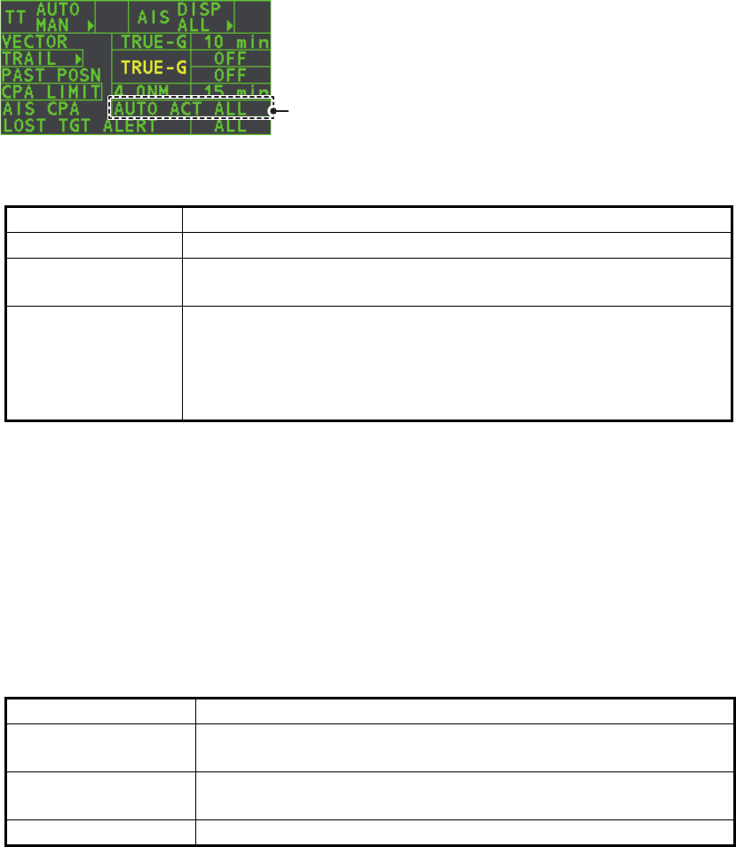
4.4.2 How to enable/disable the AIS auto activate function
Use the [CPA AUTO ACTIVATE] box at the bottom right corner to enable or disable
the AIS auto active function.
1. Place the cursor on the [CPA AUTO ACTIVATE] box, then press the left button
several times to display the desired auto activate function.
4.4.3 How to limit the functions of the AIS auto activate function
You can limit the function of the AIS auto active function by distance from own ship,
ship's speed, ship class, and ship's length.
1. Open the [MAIN MENU].
2. Select [TT•AIS], then press the ADJUST knob.
3. Select [CPA AUTO ACTIVATE], then press the ADJUST knob.
4. Referring to the table below, select the appropriate filtering type, then press the
ADJUST knob.
5. Rotate the ADJUST knob to set the selected filter’s options, then press the
ADJUST knob.
6. Close the menu.
Filter type Definition
[OFF] Disable the AIS auto activate function.
[AUTO ACT ALL] Activation against AIS targets whose CPA or TCPA is less than
set in section 3.13
[AUTO ACT FILT] Activation against AIS targets which meet the following criteria:
• AIS target that meets the criteria set with [CPA AUTO
ACTIVATE] on the [TT•AIS] menu.
• CPA or TCPA of an AIS target is smaller than that set in section
section 3.13.
Filter type Definition
[MAX RANGE] Any AIS targets beyond the range set here will not be
automatically activated.
[MIN SHIP SPEED] Any AIS targets slower than this setting will not be automatically
activated.
[EXCEPT CLASS B] Select ON to prevent activation of AIS targets class B.
Select the AIS CPA box, then press the left
button to cycle through AIS display modes.

4. AIS OPERATION
4-7
4.5 How to Sleep AIS Targets
4.5.1 How to sleep individual AIS targets
You can “sleep” an AIS target as below when the screen becomes filled with targets,
which might prevent important radar and AIS displays from being identified.
Note: Targets that have been activated automatically cannot be “slept”.
1. Place the cursor on the target to be slept, then press the key. The symbol
for the slept target changes as indicated in the table in section 4.2.
4.5.2 How to sleep all AIS targets
1. Select the [AIS DISP] box, then press the right button to open the [AIS TARGET]
menu.
2. Select [SLEEP ALL TGTS], then press the ADJUST knob.
3. Select [YES] or [NO] as appropriate, then press the ADJUST knob.
4. Close the menu.
4.6 How to Set Up For a Voyage
At the start of a voyage, following five items must be input from the [VOYAGE DATA]
menu: navigational status, ETA, destination, draught and crew.
1. Select the [AIS DISP] box, then press the right button to open the [AIS TARGET]
menu.
2. Select [VOYAGE DATA], then press the ADJUST knob.
3. Select [NAV STATUS], then press the ADJUST knob.
4. Select the appropriate navigation status number, referring to the table below, then
press the ADJUST knob.
Nav
Status
No.
Meaning
00 Underway using engine (default)
01 At anchor
02 Not under command
03 Restricted maneuverability
04 Constrained by her draft
05 Moored
06 Aground
07 Engaged in fishing
08 Under way sailing
09 Reserved for high speed craft (HSC)
10 Reserved for wing in ground (WIG, for example, hydrofoil)
11 Power-driven vessel (ahead/astern)
12 Power-driven vessel (ahead/alongside)
13 Reserved for future use
Continued on following page.
4. AIS OPERATION
4-8
5. Select [ETA], then press the ADJUST knob.
6. Using the ADJUST knob, set the estimated day of the month to arrive, then press
the ADJUST knob.
7. Select [DESTINATION], then press the left button.
8. Using the ADJUST knob, set the destination in alphanumeric characters, then
press the ADJUST knob. (Max. 20 characters)
9. Select [DRAUGHT], then press the ADJUST knob.
10. Using the ADJUST knob, set the ship’s draught, then press the ADJUST knob.
11. Select [CREW], then press the ADJUST knob.
12. Using the ADJUST knob, set the number of crew on-board, then press the
ADJUST knob.
13. Close the menu.
Continued from previous page.
14 AIS SART (No use)
15 AIS SART TEST
Nav
Status
No.
Meaning
08
Currently selected digit is highlighted by the cursor.
Rotate the ADJUST Rotokey to adjust the day.
Press the ADJUST Rotokey to move to the next digit.
GOLD COAST
Currently selected character is highlighted by the cursor.
Rotate the ADJUST Rotokey to select the desired character.
Press the ADJUST Rotokey to move to the next character.
4. AIS OPERATION
4-9
4.7 Target Data
You can display an AIS target’s data by selecting it on the display, when the AIS
function is set for [AIS DISP FILT].
4.7.1 How to display target data in the data display area
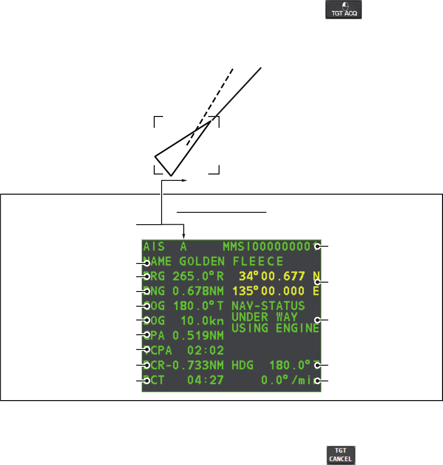
Place the cursor on a desired tracked target and press the key. The target is
highlighted with square box and the selected AIS target’s data is shown in AIS target
data box in the data display area, on the right side of the screen.
4.7.2 How to remove target data from the display area
Place the cursor on a desired tracked target and press the key. The select tar-
get’s data is no longer displayed in the data display area.
Location of target data box
Target’s MMSI ID
Name of targeted ship
Bearing to target
Range to target
Target’s course
Target’s speed
Target’s CPA
Target’s TCPA
Target’s bow cross range
Target’s bow cross time
Target’s coordinates
Target’s heading
Target’s rate of turn
Target’s nav status
A
AIS target data box

4. AIS OPERATION
4-10
4.8 How to Adjust AIS Symbol Attributes
The AIS symbol’s brilliance, size and color can be adjusted.
4.8.1 How to adjust the AIS symbol brilliance
1. Place the cursor on the [BRILL] box, then press the right button. The [BRILL]
menu is displayed.
2. Select [AIS SYMBOL], then press the ADJUST knob.
3. Using the ADJUST knob, adjust the brilliance to the appropriate level, then press
the ADJUST knob.
4. Press the right button to close the menu.
4.8.2 How to adjust the AIS symbol color
1. Open the [MAIN MENU].
2. Select [TT•AIS], then press the ADJUST knob.
3. Select [TT•AIS SYMBOL], then press the ADJUST knob.
4. Select [SYMBOL COLOR], then press the ADJUST knob.
5. To cycle through the colors for the AIS symbols, rotate the ADJUST knob.
To select the color, press the ADJUST knob. The available colors, in order, are:
[GRN] (Green) [BLU] (Blue) [CYA] (Cyan) [MAG] (Magenta)
[WHT] (White) [GRN]...
6. Select [AIS SCALED SYMBOL], then press the ADJUST knob.
7. Select [OFF] or [ON] as appropriate, then press the
ADJUST knob.
[OFF]: All AIS symbols are displayed in the same size.
[ON]: AIS symbols are displayed in scale, according to the
ship length.
The figure to the right shows examples of standard and
scaled symbols.
8. Close the menu.
4.8.3 How to adjust the ATON symbol color
1. Open the [MAIN MENU].
2. Select [TT•AIS], then press the ADJUST knob.
3. Select [TT•AIS SYMBOL], then press the ADJUST knob.
4. Select [ATONSYMBOL COLOR], then press the ADJUST knob.
5. To cycle through the colors for the ATON symbols, rotate the ADJUST knob.
To select the color, press the ADJUST knob. The available colors, in order, are:
[GRN] (Green) [BLU] (Blue) [CYA] (Cyan) [MAG] (Magenta)
[WHT] (White) [GRN]...
6. Close the menu.
Standard
symbol
Scaled
symbol
4. AIS OPERATION
4-11
4.9 Past Position Display
4.9.1 How to adjust the past position plotting interval
The plotting interval determines how often the target’s past position is refreshed. To
change the plotting interval do the following:
Place the cursor on the plotting interval for the [Past POSN] indication in the [TT•AIS]
box, then press the left button to cycle through the intervals.
The available options, in order, are:
[OFF] [30 SEC] [1 MIN] [2 MIN] [3 MIN] [6 MIN] [OFF]...
To erase all past position points and disable the past position display, select [OFF].
4.9.2 How to select the number of past position points to be
displayed
1. Open the [MAIN MENU].
2. Select [TT•AIS], then press the ADJUST knob.
3. Select [TT•AIS SYMBOL], then press the ADJUST knob.
4. Select [TT•AIS PAST POSN POINTS], then press the ADJUST knob.
5. Select [5] or [10] as appropriate, then press the ADJUST knob.
6. Close the menu.
4.9.3 Past position display orientation
Past position orientation, true or relative, is controlled with [TRAIL MODE] in the
[TRAIL] context menu. To adjust the trail orientation, see paragraph 1.36.1.
4.9.4 Stabilization in true motion
True motion past position display can be ground stabilized or sea stabilized. The
[TRAIL] box shows current stabilization as "TRUE-G" or "TRUE-S". To change
stabilization mode, open the [SHIP SPEED MENU] menu and set [SHIP SPEED] to
[LOG(BT)] (ground stabilization) or [LOG(WT)] (sea stabilization).
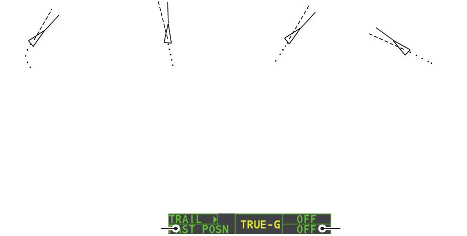
The past position display shows equally time-spaced dots marking past positions of ac-
tivated AIS targets. A new dot is added at preset time intervals until the preset number is
reached. If a target changes its speed, the spacing will be uneven. If it changes course,
its plotted course will not be a straight line.
Below are examples of past position displays.
(a) Ship turning (b) Ship running straight (c) Ship reduced speed (d) Ship increased speed
Past POSN indication Plotting interval
4. AIS OPERATION
4-12
4.10 Lost Target
A target is declared a lost target when it fails to produce data for six minutes or five
reporting intervals, whichever is the shorter. When this occurs, the target is marked
with the (flashing) lost target symbol and the message "LOST" appears in the Alert
Box. To acknowledge a lost target, press the key, or use the Touchpad to se-
lect the [ALERT] box then press the left button.
4.10.1 How to set the lost target filter
If there are a lot of AIS targets in your area, the lost target alert can sound frequently.
In this case you may wish to have the alert ignore lost targets whose range, speed,
class or length are below the threshold value you specify.
1. Open the [MAIN MENU].
2. Select [TT•AIS], then press the ADJUST knob.
3. Select [AIS LOST FILTER], then press the ADJUST knob.
4. Referring to the table below, select the appropriate filtering type, then press the
ADJUST knob.
5. Select [ON], then press the ADJUST knob. The settings can now be adjusted.
6. Rotate the ADJUST knob to adjust the setting as required, then press the
ADJUST knob to apply the setting.
7. Close the menu.
4.10.2 How to enable/disable the lost target alert
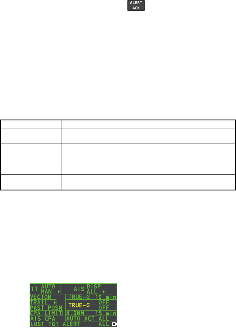
The [LOST TARGET ALERT] box at the bottom right corner enables and disables the
lost target alert. Select the box with the cursor, then press the left button to select
[OFF], [ALL] or [FILT] as appropriate.
• [OFF]: Disable the alert.
• [ALL]: Enable the alert for all lost targets, including filtered targets.
• [FILT]: Enable the alert for all lost targets, excluding filtered targets.
Filter type Definition
[MAX RANGE] Any AIS targets beyond the range set here will not trigger the
lost target alert.
[MIN SHIP SPEED] Any AIS targets slower than this setting will not trigger the lost
target alert.
[EXCEPT CLASS B] Select ON to prevent AIS targets class B triggering the lost
target alert.
[MIN SHIP LENGTH] Any AIS targets whose length is shorter than this setting will not
be automatically activated.
Lost target alert box
4. AIS OPERATION
4-13
4.11 ROT Setting
You can set the lower limit of the ROT (Rate Of Turn) at which the heading line on
target symbols will point in direction of turning of the vessel.
ROT display
1. Open the [MAIN MENU].
2. Select [TT•AIS], then press the ADJUST knob.
3. Select [TT•AIS SYMBOL], then press the ADJUST knob.
4. Select [AIS ROT TAG LIMIT], then press the ADJUST knob. The settings can now
be adjusted.
5. Using the ADJUST knob, adjust the ROT as appropriate. Rotate the ADJUST
knob to adjust the value, press the ADJUST knob to move to the next digit. The
setting range is 000.0°/min to 720.0°/min.
6. Close the menu.
4.12 AIS Collision Alarm (CPA, TCPA)
This radar calculates CPA and TCPA by using own ship and relative target positions.
An AIS dangerous target is one whose CPA and TCPA are within the range of the CPA
and TCPA limits set in the TT/AIS box. The AIS symbol of an AIS dangerous target is
red and flashing, and is announced with the Alert 536 "AIS CPA/TCPA". After the alert
is acknowledged the target symbol is displayed in red color.
4.12.1 How to set the CPA and TCPA ranges
CPA and TCPA ranges can be adjusted from
the appropriate indication in the [TT•AIS]
box. If the CPA/TCPA settings are displayed
as “OFF”, place the cursor on the CPA limit
indication, then press the left button.
1. Place the cursor on the indication you wish to adjust.
Ship turning
to starboard
Thicker than
activated target
When a sleeping or an activated target violates the CPA/TCPA
alarm setting its symbol changes to the dangerous target
symbol (red and flashing) and the message AIS COLLISON
appears. Press the ALARM ACK key (or click the [ALERT] box
with the left button) to acknowledge the CPA/TCPA alarm. The
audible alarm is silenced and the symbol stops flashing.
Take appropriate action to avoid collision.
Dangerous target
CPA setting
TCPA setting

4. AIS OPERATION
4-14
2. Press the left button, or rotate the ADJUST knob, to adjust the settings as
required. The settings options are outlined in the table below.
Indication Key Settings options
CPA Left button 0.5, 1, 1.5, 2, 3, 4, 5, 6 (nm)
ADJUST
knob
0.1-20 (nm), 0-10 nm in 0.1 nm increments, 10 nm
increments thereafter
TCPA Left button 1, 2, 3, 4, 5, 6, 12, 15 (minutes)
ADJUST
knob
1-60 minutes, 1-minute increments
4. AIS OPERATION
4-15
4.13 How to associate TT and AIS Targets
An AIS-equipped ship is usually displayed by two symbols on the radar display. This
is because the AIS ship position is measured by a GPS navigator (L/L) whereas the
radar detects the same ship by PPI principle (range and bearing relative to own ship
radar antenna).
To avoid the presentation of two target symbols for the same physical target, use the
"association" function. If target data from both AIS and TT are available and if the as-
sociation criteria are fulfilled, either the AIS or TT symbol is presented according to the
association method selected.
Association will not happen between AIS and TT if the AIS target is sleeping or the AIS
target is lost.
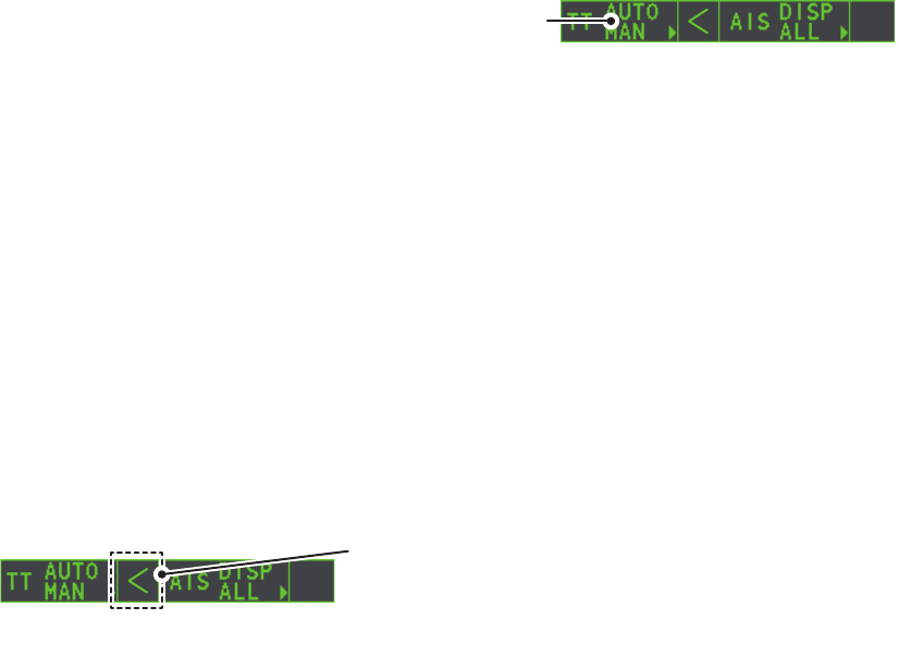
1. Confirm that the [TT ACQ
MODE] indication shows
"AUTO", "AUTO MAN" or
"MAN".
2. Open the [MAIN MENU].
3. Select [TT•AIS], then press the ADJUST knob.
4. Select [ASSOCIATION], then press the ADJUST knob.
5. Select [ASSOCIATION TGT], then press the ADJUST knob.
6. Select [OFF], [AIS] or [TT], as appropriate, to select which symbols and data to
display when the association criteria are met.
• [OFF]: Disable association.
• [AIS]: Use AIS symbols and AIS data.
• [TT]: Use TT symbols and TT data.
Note: Association can also be switched on and off from the screen by left-clicking
the Association Usage icon, shown below.
7. Referring to the table below, set the association criteria. Rotate the ADJUST knob
to adjust the value, press the ADJUST knob to move to the next digit.
8. Close the menu.
[GAP]: Range in bearing direction between AIS target and tracked target.
(setting range: 0.000-0.050 (nm))
[RANGE]: Range direction difference from own ship to AIS target and tracked
target. (setting range: 0.000-0.100 (nm))
[BEARING]: Bearing difference from own ship to AIS target and tracked target.
(setting range: 0.0-9.9 (°))
[SPEED]: Speed difference between AIS target and tracked target.
(setting range: 0.0-6.0 (kn))
[COURSE]: Course difference between AIS target and tracked target.
(setting range: 0.0-25.0 (°))
TT ACQ MODE
indication
Place the cursor on the association icon, then press the
left button to change the association setting.
>: Use TT Symbols and data.
<: Use AIS symbols and data.
No indication: Association is disabled.
4. AIS OPERATION
4-16
When the association criteria (gap, range, bearing, speed, and course) is met, and the
ASSOCIATION TARGET setting is [AIS], the TT symbol is erased and only the AIS
symbol is displayed. Further, "ASSOCIATION" appears in the Alert Box.
All default association settings are restored whenever the power is turned on.
4.14 How to View Own Ship Data
Own ship’s static data (type of ship, call sign, name and position of internal and
external GPS antennas) can be viewed as follows:
1. Select the [AIS] box at the right of the screen, then press the right button. The
[AIS TARGET MENU] is displayed.
2. Select [STATIC DATA], then press the ADJUST knob.
3. Close the menu.
4.15 How to Use AIS Messages
You can transmit and receive messages via the AIS, to a specified destination (MMSI)
or all ships in the area. Messages can be sent to warn of safety of navigation, for ex-
ample, an iceberg sighted. Routine messages are also permitted.
Short safety related messages are only an additional means to broadcast safety infor-
mation. They do not remove the requirements of the GMDSS.
AIS box
1 BACK
TYPE OF SHIP
000
ALL SHIPS OF
THIS TYPE
CALL SIGN
(call sign here)
NAME
(ship name here)
EXT GPS ANT POSN
A: 000m B: 000m
C: 00m D: 00m
[STATIC DATA]
A
B
CD
4. AIS OPERATION
4-17
4.15.1 How to create and save messages
Up to ten messages can be saved at any time. To create and save a message, do the
following:
Note: The MMSI of the receiving ship can be automatically set by selecting
[TRANSMIT MESSAGE] from the pop up menu. To show the pop up menu, select the
receiving ship’s data in the AIS data display area, then press the right button.
1. Select the [AIS] box at the right of the screen, then press the right button. The
[AIS TARGET MENU] is displayed.
2. Select [TRANSMIT MESSAGE], then press the ADJUST knob.
3. Select [ADDRESS TYPE], then press the ADJUST knob.
4. Select [ADDRESSED] (message for a specific MMSI. Automatically selected if the
MMSI is automatically using the data display.) or [BROADCAST] (message to all
AIS-equipped vessels within the area), then press the ADJUST knob.
5. Select [MESSAGE TYPE], then press the ADJUST knob.
6. Select [SAFETY] (for safety messages) or [BINARY] (for routine messages), then
press the ADJUST knob.
7. For [ADDRESSED] message, do this step. For [BROADCAST] message, or if
[TRANSMIT MESSAGE] was selected from the AIS data display pop up menu, go
to step 8.
1) Select [MMSI No.], then press the ADJUST knob.
2) Using the ADJUST knob, set the receiving ship’s MMSI.
8. Select [CHANNEL], then press the ADJUST knob.
9. Select the AIS channel to transmit your message over: [A], [B], [A or B], or [A and
B], the press the ADJUST knob.
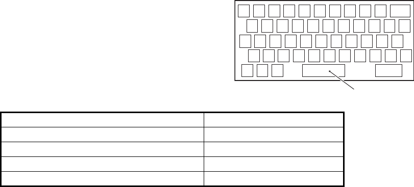
10. Select [EDIT], then press the ADJUST knob. A software keyboard appears at the
bottom of the menu.
11. Select the character desired, then press
the left button.
The maximum number of characters
which can be entered depends on the
message type, as shown in the table
below.
12. Select [OK], then press the ADJUST knob.
13. Select [SAVE FILE], then press the ADJUST knob.
14. Select the appropriate number, then press the ADJUST knob.
15. Close the menu.
Message type Max. characters allowed
Safety message broadcast 161
Binary message broadcast 156
Safety message addressed to MMSI 156
Binary message addressed to MMSI 151
1 2 3 4 5 6 7 8 9 0 BS
Q W E R T Y U I O P -
A> S D F G H J K L +
Z= X C V B N M , . ?
”# / END
Space
4. AIS OPERATION
4-18
4.15.2 How to transmit messages
1. Select the [AIS] box at the right of the screen, then press the right button. The
[AIS TARGET MENU] is displayed.
2. Do one of the following:
a) Create a message, as described in paragraph 4.15.1.
b) Use a file saved in the memory by selecting [TRANSMIT MESSAGE] followed
by [OPEN FILE].
3. Select [TRANSMIT MESSAGE] to transmit the message.
4. Close the menu.
The indication "AIS TRANSMITTING" appears while sending the message.
"TRANSMIT ERROR" appears if an error occurred while transmitting the message.
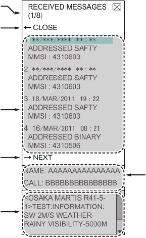
4.15.3 How to view messages
When an AIS message is received, the display shows an appropriate icon to alert you.
If [AUTO DISP MESSAGE] in the [AIS TARGET MENU] is set to [ON], messages are
automatically displayed upon receipt. The system stores up to 20 AIS messages.
When the storage capacity is reached the oldest AIS message is automatically erased
to make room for the latest. Note that received messages and alarm messages are
not backed up when the power is turned off.
1. Select the [AIS] box at the right of the screen, then press the right button. The
[AIS TARGET MENU] is displayed.
2. Select [RECEIVED MESSAGES], then press the ADJUST knob. Up to four
messages are displayed per page and a total of 200 messages can be stored.
3. Select the message to be displayed, then press the ADJUST knob.
4. The message details are displayed below the message list.
5. Close the menu.
Currently displayed page no.
Message list
Display next page.
Name and Call Sign of
selected message’s sender.
Message details
Close message list.
When displayed as
“BACK”, goes back
one page in the list.

4. AIS OPERATION
4-19
4.15.4 How to automatically display received messages
1. Select the [AIS] box at the right of the screen, then press the right button. The
[AIS TARGET MENU] is displayed.
2. Select [AUTO DISP MESSAGE], then press the ADJUST knob.
3. Select [ON] to display messages as they are received, [OFF] to disable the
automatic display, then press the ADJUST knob.
4. Close the menu.
4.15.5 How to display AIS alert messages
The AIS transponder outputs various alert messages. To view the alert list:
1. Select the [AIS] box at the right of the screen, then press the right button. The
[AIS TARGET MENU] is displayed.
2. Select [AIS ALERT MESSAGES], then press the ADJUST knob.
3. Close the menu.
4.16 AIS System Messages
AIS system messages are displayed at the bottom right corner of the screen. The table
below shows the AIS system messages and their meanings.
Message Priority Meaning
"AIS COLLISION" Alarm CPA and TCPA of an activated AIS target are
below value set on the menu.
"AIS NEW TARGET" Warning AIS target has entered an acquisition zone.
"AIS LOST" Warning Lost target. An activated target is declared a lost
target when it fails to produce data for six minutes
or five reporting intervals, whichever is the shorter.
"AIS TARGET FULL" Warning The radar only displays the closest 1000 AIS
targets from own ship.
"RECEIVE" Warning Not receiving AIS data from own AIS (VDO
message).
"AIS TARGET 95%" Caution Appears when capacity for AIS targets is 95% full.
"ASSOCIATION" Caution Tracked target merged with AIS target. The
indication disappears when the target no longer
meets the criteria set in section 4.12.
When the message "RECEIVE" is displayed,
"ASSOCIATION" is not displayed.
"TRANSMIT ERROR" Caution Could not send AIS message.
"AIS TRANSMITTING" Caution AIS message is being transmitted.
4. AIS OPERATION
4-20
This page is intentionally left blank.

5-1
5. VIDEO PLOTTER OPERATION
The video plotter has the following functions:
• Enter waypoints (up to 98) and marks.
• Creates and displays radar maps.
• Own ship track plotting
• Able to save marks and tracks on removable SD card.
5.1 Orientation Modes
Six orientation modes are available:
[HEAD UP RM], [STAB HEAD UP RM],[STERN UP RM], [COURSE UP RM],
[NORTH UP RM], [NORTH UP TM] (True Motion).
Note 1: The [STERN UP RM] orientation mode is only available it has been set to [ON]
in [STERN UP RM] in the [INITIAL SETTING] [OPERATION] menu.
Note 2: The screen may flash when the heading is changed more than one degree in
the [HEAD UP RM] or [STAB HEAD UP RM] mode.
Automatic resetting of own ship mark in true motion mode
In the true motion mode, the own ship mark is automatically returned sternward 75%
from the screen center when it reaches a location 50% of the display radius.
To select an orientation mode, see "How to select an presentation mode" on page 1-
31.
5. VIDEO PLOTTER OPERATION
5-2
5.2 Radar Map
A radar map is a combination of map lines and symbols whereby the user can define
and input the navigation data, route planning and monitoring data. The radar map can
contain 5,000 points of data. Inscribed marks are retained when the power is turned
off.
The radar map is reference to the WGS-84 datum and is displayed only when there is
valid position data input. The radar map does not affect any radar functions.
5.2.1 How to show/hide the radar map
Select the [MAP] indication in the [RADAR CONTROL
BOX] at the left-side of the screen, then press the left
button to display or hide the radar map.
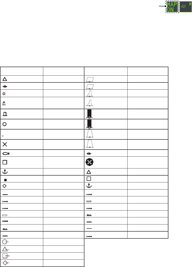
5.2.2 Radar map marks
To inscribe/remove marks or change mark colors on the radar map, see "How to Use
Marks" on page 1-55. The following mark icons are available.
Radar map
indicator
IMO type*2 Non-IMO type*1
Mark Red Buoy
Danger Highlight Green Buoy
Buoy Red Buoy
Buoy Green Buoy
Buoy Red Buoy
Buoy Green Buoy
Buoy Red Buoy
Danger Highlight Green Buoy
Mark Purple Danger Highlight
Mark Purple Danger Highlight
Mark Orange Mark
Mark Orange Mark
Mark Orange Mark
Mark Purple Navline (map)
Mark White Coastline
Nav Line (map) Gray Contour Line
Coastline Purple Danger Highlight
Contour Purple (cable) Danger Highlight
Prohibited Area Orange Mark
(cable) Danger Highlight Orange Mark
(w/line) Buoy
(w/line) Mark
(w/line) Mark
(w/line) Mark
Item on
MARK menu
Item on
MARK menu
*
1
: Colors for non-IMO marks may be
set by the user.
*
2
: Colors for IMO marks are fixed as
indicated.

5. VIDEO PLOTTER OPERATION
5-3
5.3 How to Align the Radar Map
When there is positional error between the radar screen and radar map marks and
lines, do the following to correct it.
Note: Activating/deactivating the [MAP ALIGN] function resets own ship track and all
trails.
1. Select the operational display area, then press the right button. The [CURSOR]
menu is displayed.
2. Select [MAP ALIGN], then press the left button. The cursor color changes to
blue.
3. Move the cursor to align the radar map with the radar screen, then press the left
button. The indication "MAP ALIGN" appears on the right side of the operational
display area.
Display indications affected by map alignment
The following items are also re-aligned when the [MAP ALIGN] function is activated.
Display indication unaffected by map alignment
The following items are not re-aligned when the [MAP ALIGN] function is activated.
5.3.1 How to disable the map alignment
1. Select the operational display area, then press the right button. The [CURSOR]
menu is displayed.
2. Select [MAP ALIGN], then press the left button. The cursor color changes to
blue.
3. Press and hold the left button. The "MAP ALIGN" indication is cleared.
• Radar echoes
• Cursor position co-ordinates
• EBL offsets (STAB HDG & STAB
NORTH modes only)
• PI Lines
• Acquisition Zone set area
• Barge mark
• TT symbols
• EBL/VRM reference points
• ZOOM window display
• Anchor Watch
• AIS symbol vector display (REL mode
only)
• Own ship location co-ordinates (POSN
display only)
• WPT/Route
• DROP mark
• EBL offsets (STAB GND mode only)
• AIS symbol vector display (TRUE mode
only)
• AIS symbols
• MOB
• TT symbol vector display
• Zoom window display (STAB GND
mode only)
5. VIDEO PLOTTER OPERATION
5-4
5.4 Own Ship’s Track
A total of 1,200 points are allotted for storage of own ship’s track, marks and lines.
When this memory becomes full, the oldest track is deleted to make room for the
latest. For that reason you may want to adjust the recording interval to conserve the
memory.
The table below shows the relation between plotting interval settings and maximum
track recording time.
5.4.1 How to set the plotting interval
1. Open the [MAIN MENU].
2. Select [MARK], then press the ADJUST knob.
3. Select [OWN TRACK], then press the ADJUST knob.
4. Select [SAVE INTERVAL], then press the ADJUST knob.
5. Select the appropriate setting, then press the ADJUST knob.
6. Close the menu.
5.4.2 How to set the own ship track color
1. Open the [MAIN MENU].
2. Select [MARK], then press the ADJUST knob.
3. Select [OWN TRACK], then press the ADJUST knob.
4. Select [OWN TRACK COLOR], then press the ADJUST knob. The following
colors are available.
5. Select the appropriate setting, then press the ADJUST knob.
6. Close the menu.
Interval Max. Recording Time Interval Max. Recording Time
15 s 5 hours 3 min 60 hours
30 s 10 hours 6 min 120 hours
1 min 20 hours 15 min 300 hours
2 min 40 hours DRAW ONLY No track data recorded.
Non-IMO type IMO type
• [RED] (Red)
• [GRN] (Green)
• [BLU] (Blue)
• [YEL] (Yellow)
• [CYA] (Cyan)
• [MAG] (Magenta)
• [WHT] (White)
OWN TRACK COLOR is not adjustable for IMO type radars.
Own track is displayed in (Cyan) color.
5. VIDEO PLOTTER OPERATION
5-5
5.4.3 How to delete the own ship track
There are three methods to delete the own ship track: by percentage of track, by track
color or by cursor selection.
How to erase tracks by percentage
1. Open the [MAIN MENU].
2. Select [MARK], then press the ADJUST knob.
3. Select [OWN TRACK], then press the ADJUST knob.
4. Select [DELETE OWN TRACK], then press the ADJUST knob.
5. Select the percentage of the track you wish to delete, then press the ADJUST
knob. The available options are: [30%], [50%], [80%] or [ALL].
6. Close the menu.
How to erase tracks by color (For non-IMO type only)
1. Open the [MAIN MENU].
2. Select [MARK], then press the ADJUST knob.
3. Select [OWN TRACK], then press the ADJUST knob.
4. Select [DELETE OWN TRACK], then press the ADJUST knob.
5. Select the color of the track you wish to delete, then press the ADJUST knob. The
available options are: [RED], [GRN], [BLU], [YEL], [CYA], [MAG] or [WHT].
6. Close the menu.
How to erase tracks with the cursor (For non-IMO type only)
1. Open the [MAIN MENU].
2. Select [MARK], then press the ADJUST knob.
3. Select [OWN TRACK], then press the ADJUST knob.
4. Select [DELETE OWN TRACK], then press the ADJUST knob.
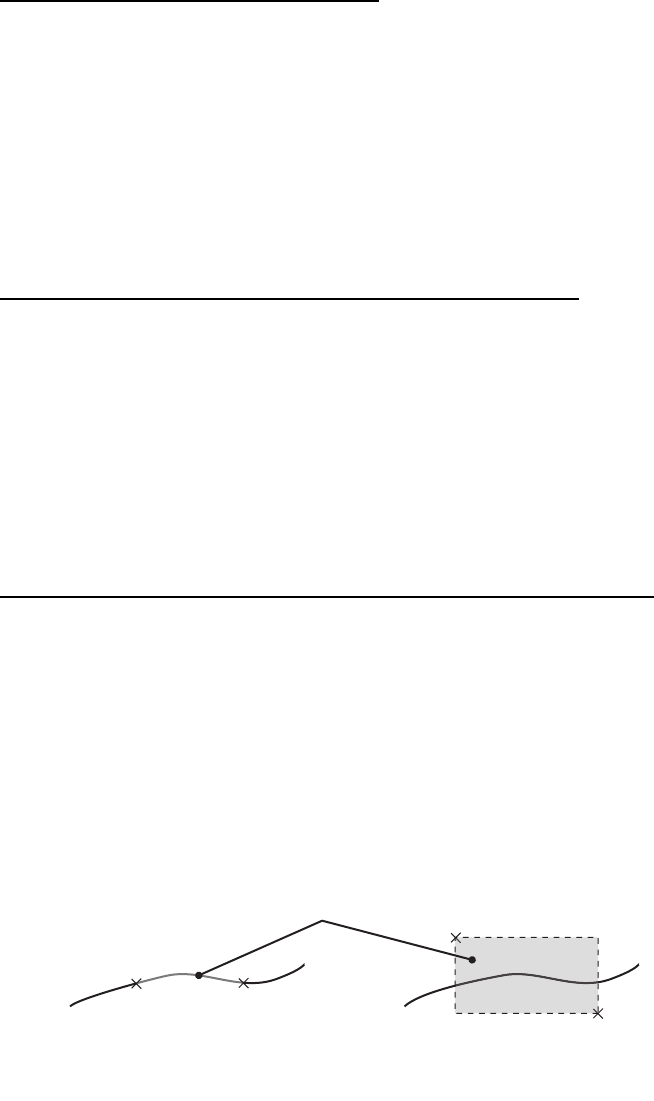
5. Select [2POINTS] or [AREA] as appropriate, then press the ADJUST knob. The
cursor jumps into the operational display area.
[2POINTS]: Delete track between two points
[AREA]: Delete all track within an area
6. Place the cursor on the first point (A), then press the left button.
7. Place the cursor on the second point (B), then press the left button. If [AREA] was
selected at step 5, the two points form a square.
8. Close the menu.
[2POINTS] method [AREA] method
A
A
B
B
Area to be deleted

5. VIDEO PLOTTER OPERATION
5-6
5.5 How to Use Waypoints
A particular location is known as a “waypoint”, whether it be a starting point,
a destination point or an intermediate point on a voyage. This radar system can store
100 waypoints. Waypoints 1 to 98 are user set waypoints, waypoint 99 is reserved for
external input, waypoint 100 is reserved for MOB (Man Over Board). Waypoints can
be entered with the cursor, or from the menu (manual input of latitude and longitude).
Waypoints 1 to 98 can be edited from the menu.
5.5.1 How to enter waypoints
How to enter waypoints with the cursor
1. Select the [MARK] box, then press the right button. The [MARK] menu is dis-
played.
2. Select [MARK KIND], then press the ADJUST knob.
3. Select the appropriate waypoint number group for the new waypoint, then press
the ADJUST knob.
The available groups are: [WP1 to WP50] or [WP51 to WP98].
4. Rotate the ADJUST knob to select the waypoint number for new waypoint, then
press the ADJUST knob. The cursor jumps inside the operational display area.
5. Place the cursor on the location where the new waypoint is to be inscribed, then
press the left button.
6. Repeat steps 4 and 5 to inscribe other waypoints.
7. Press the right button to complete waypoint inscription.
How to enter/edit waypoints from the menu
Note: Waypoints which are part of a route that is currently in use cannot be edited.
1. Open the [MAIN MENU].
2. Select [NAVLINE•WPT], then press the ADJUST knob.
3. Select [WPT SET], then press the ADJUST knob.
4. Select [WPT NO. SELECT], then press the ADJUST knob.
5. Rotate the ADJUST knob to select a waypoint number, then press the ADJUST
knob.
6. To edit or input a waypoint name, select [WPT NAME], then press the ADJUST
knob. The software keyboard is displayed. To skip naming the waypoint, go to
step 7.
1) Select a character, then press the left button. Repeat the process to name the
waypoint. A total of 15 characters can be used when naming the waypoint.
2) Select [END] to complete naming the waypoint.
7. Select [WPT L/L], then press the ADJUST knob. The settings can now be
adjusted.
8. Rotate the ADJUST knob to select a digit, then press the ADJUST knob to move
to the next digit. Use this method to set the Latitude and Longitude.
9. Close the menu.
5. VIDEO PLOTTER OPERATION
5-7
5.5.2 How to erase waypoints
1. Open the [MAIN MENU].
2. Select [NAVLINE•WPT], then press the ADJUST knob.
3. Select [WPT SET], then press the ADJUST knob.
4. Select [WPT NO. SELECT], then press the ADJUST knob.
5. Select [CLEAR DATA], then press the ADJUST knob.
6. Select [YES] or [NO] as appropriate, then press the ADJUST knob.
7. Close the menu.
5.5.3 How to display the waypoint list
1. Open the [MAIN MENU].
2. Select [NAVLINE•WPT], then press the ADJUST knob.
3. Select [WPT LIST], then press the ADJUST knob.
4. Close the menu.
5.5.4 How to show/hide the waypoint name/number
1. Open the [MAIN MENU].
2. Select [NAVLINE•WPT], then press the ADJUST knob.
3. Select [DISP WPT NO.] or [DISP WPT NAME] as appropriate, then press the
ADJUST knob.
4. Select [YES] to show the waypoint name/number, or [NO] to hide the waypoint
name/number, then press the ADJUST knob.
5. Close the menu.
5. VIDEO PLOTTER OPERATION
5-8
This page is intentionally left blank.
6-1
6. MAINTENANCE,
TROUBLESHOOTING
Periodic checks and maintenance are important for proper operation of any electronic
system. This chapter contains maintenance and troubleshooting instructions to be fol-
lowed to obtain optimum performance and the longest possible life of the equipment.
Before attempting any maintenance or troubleshooting procedure please review the
safety information below.
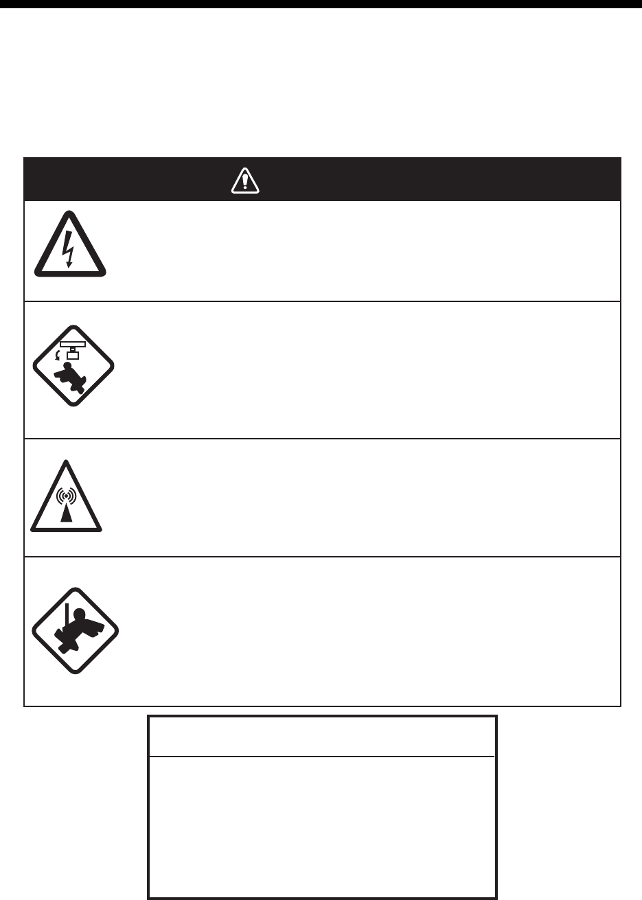
WARNINGWARNING
Do not open the equipment.
Hazardous voltage which can cause electrical shock exists inside the
equipment. Only qualified personnel should work inside the equipment.
Turn off the radar power switch before servicing the antenna
unit. Post a warning sign near the switch indicating it should
not be turned on while the antenna unit is being serviced.
Prevent the potential risk of being struck by the rotating antenna.
Wear a safety belt and hard hat when working on the
antenna unit.
Serious injury or death can result if someone falls from the radar
antenna mast.
A transmitting radar antenna emits electromagnetic waves,
which can be harmful, particularly to the eyes.
NOTICE
Do not apply paint, anti-corrosive sealant or
contact spray to coating or plastic parts of
the equipment.
Those items contain organic solvents that can
damage coating and plastic parts, especially
plastic connectors.

6. MAINTENANCE, TROUBLESHOOTING
6-2
6.1 Periodic Maintenance Schedule
Regular maintenance is essential to good performance. A regular maintenance pro-
gram should be established and should at least include the items shown in the table
below.
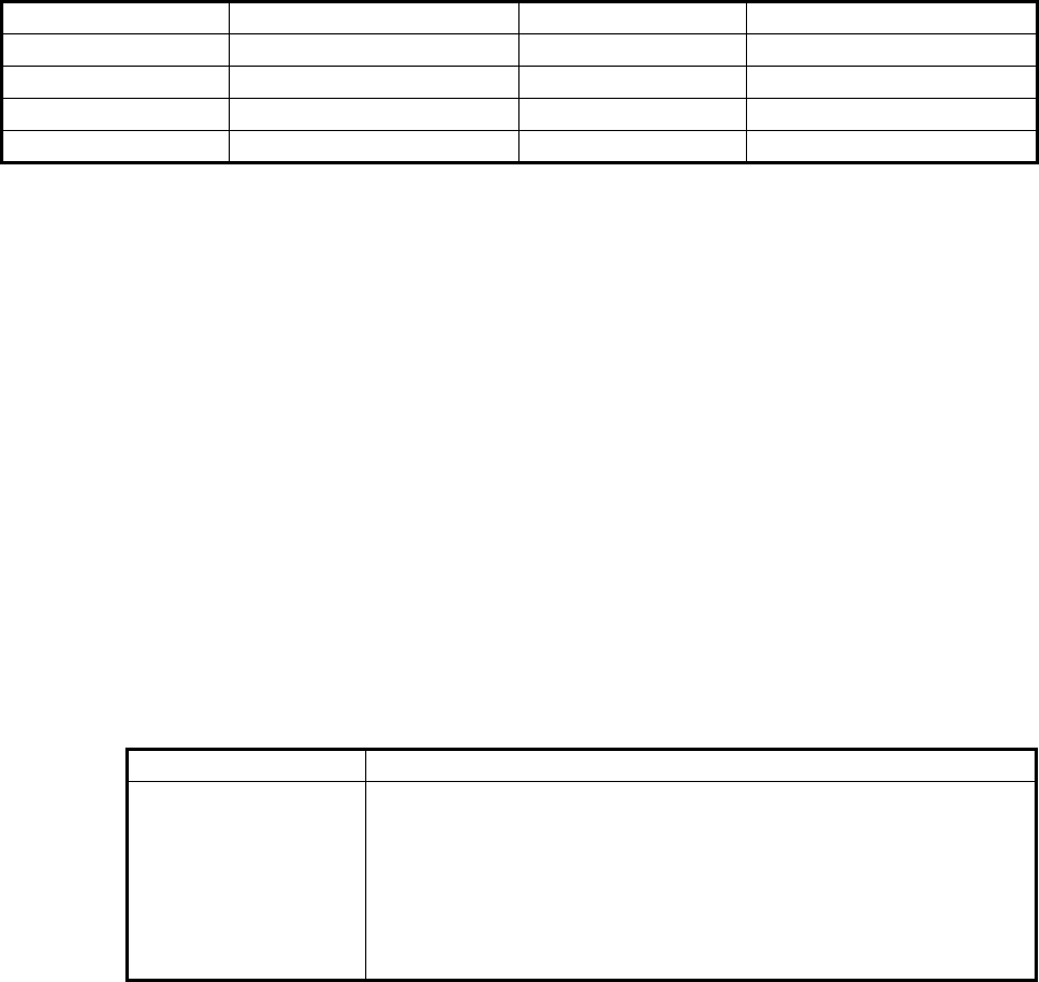
Interval Check Point Checks and measures Remarks
As
required
The LCD will in time accu-
mulate a layer of dust which
tends to dim the picture
Wipe the LCD carefully to
prevent scratching, using
tissue paper and an LCD
cleaner. To remove stub-
born dirt, use an LCD
cleaner, wiping slowly with
tissue paper so as to
dissolve the dirt. Change
paper frequently so the dirt
will not scratch the LCD.
Do not use chemical-based
cleaners to clean the LCD.
They can damage the LCD
coating.
Processor unit cleanliness Dust and dirt may be
removed with a soft cloth.
Do not use chemical-based
cleaners to clean the
processor unit. They can
remove paint and markings.
3 to 6
months
Exposed nuts and bolts on
antenna unit
Check for corroded or
loosened nuts and bolts. If
necessary, clean and
repaint them thickly.
Replace them if heavily
corroded.
Sealing compound can be
used instead of paint. Apply
a small amount of grease
between nuts and bolts for
easy removal in future.
Antenna radiator Check for dirt and cracks on
radiator surface. Thick dirt
should be wiped off with soft
cloth dampened with fresh
water. If a crack is found,
apply a slight amount of
sealing compound or
adhesive as a temporary
remedy, then call for repair.
Do not use chemical-based
cleaners for cleaning. They
can remove paint and
markings. If you need to
remove ice from the
antenna unit, use a wooden
hammer or plastic head
hammer. Cracks on the unit
may cause water ingress,
causing serious damages to
internal circuits.
Terminal strips and plugs in
antenna unit (TECHNI-
CIANS only)
Open antenna cover to
check terminal strip and
plug connections inside.
Also check the rubber
gasket of antenna covers
for deterioration.
When closing antenna
covers in position, be
careful not to catch loose
wires between covers and
unit.
6
months
to one
year
Terminal strips, sockets,
earth terminal on processor
unit
(TECHNICIANS only)
Check for loose
connections. Check
contacts and plugs for
proper seating, etc.
6. MAINTENANCE, TROUBLESHOOTING
6-3
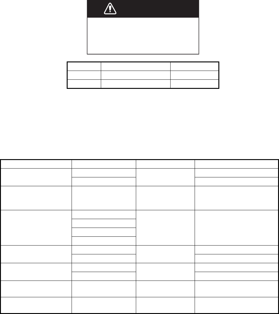
6.2 How to Replace the Fuse
A fuse is located on the front of the processor unit. The fuse protects the equipment
from reverse polarity of the ship’s mains and equipment fault. If a fuse blows, find the
cause before replacing it. Use the correct fuse. Using the wrong fuse will damage the
equipment and void the warranty.
6.3 Life Expectancy of Major Parts
This radar has consumable parts, and the table that follows shows the estimated life
expectancy for the consumable parts. Life expectancy estimates are based on use un-
der normal conditions. Request a FURUNO agent or dealer to replace the consumable
parts, to get the best performance and longest possible life from the equipment.
Note: The Magnetron is a consumable item. The effectiveness of your magnetron will
decrease over time, causing lower-than-normal signal strength and loss of echoes.
Magnetrons should be changed regularly. The table above shows the typical life-span
of a magnetron used under normal conditions.
AC/DC Type Code No.
DC FGBO 125V 15A PBF 000-155-827
AC FGBO 250V 8A PBF 000-155-843
Part Type Life expectancy Remarks
Antenna Motor D8G-516 10,000 hours
D8G-571
Carbon Brush S885026-1A-61 4,000 hours Check for wear at, or be-
fore, 2,000 hours of Tx time.
Replace if worn.
Magnetron MA1615B 5,000 hours Check no. of hours used at
Tx time. Reset time after re-
placement.
MG5436
MAF1565N
M1458F
MD Board (FAR-1518) ECA-1HG101B 55,000 hours
ECA-1HHG100B
MD Board (FAR-1528) ECA-1CHG101B 66,000 hours
ECA-1HHG100B
MU-150HD(-CV15)
Backlight
26-005-2026 60,000 hours Replace when brilliance is
uneven or too low.
MU-150HD(-CV15)
Fan Motor
MFB52A-12HA-001 40,000 hours
WARNINWARNING
Use the proper fuse.
Use of the wrong fuse can cause fire or
electrical shock.

6. MAINTENANCE, TROUBLESHOOTING
6-4
6.4 Trackball Maintenance
If the cursor skips or moves abnormally, clean the trackball using the procedure below.
1. Turn the retaining ring counterclockwise 45° to
unlock it.
2. Remove the retaining ring and ball.
3. Clean the ball with a soft, lint-free cloth, then
blow carefully into the ball-cage to dislodge
dust and lint.
4. Look for a build-up of dirt on the metal rollers.
If dirty, clean the rollers using a cotton swab
moistened lightly with isopropyl-rubbing alcohol.
5. Make sure that fluff from the swab is not left on the rollers.
6. Replace the ball and retaining ring. Be sure the retaining ring is not inserted
reversely.
6.5 Easy Troubleshooting
This section provides troubleshooting procedures that the user can follow to restore
normal operation. If you cannot restore normal operation, do not attempt to check
inside any unit. Any repair work is best left to a qualified technician.
Problem Possible cause Remedy
Key beep inaudible. Key beep turned off. Adjust key beep level in the
[OPERATION] menu, referring
to section 1.10.
Picture not updated or picture
freeze. 30 seconds after the
picture freezes, the buzzer
sounds, the ALERT ACK key
blinks and alarm signal is output.
Video freeze. Turn the power off and on again
to restore normal operation.
Power is ON but nothing appears
on monitor.
Brilliance is too low. Adjust the brilliance, referring to
section 1.4.
Marks, indications and noise
appear but no echo.
Tx high voltage protection
circuit has activated.
Reset the power to restore
normal operation.
Range changed but radar picture
does not change.
Defective range key or video
freeze up.
Adjust the range with the
control unit, or the [RANGE]
box several times.
If unsuccessful, replacement of
keypad may be required. If that
does not work try to turn the
power off and on again to see if
the problem might be video
freeze up.
Only two PI lines when six lines
are wanted
Incorrect setting of PI line
interval
Adjust PI line interval, referring
to paragraph 1.39.2. Also, the
setting for number of PI lines to
display may be inappropriate.
Check the menu setting for
number of PI lines, referring to
paragraph 1.39.1.
Retaining ring

6. MAINTENANCE, TROUBLESHOOTING
6-5
6.6 Advanced-level Troubleshooting
This section describes how to cure hardware and software troubles that should be
carried out by qualified service personnel.
Note 1: This radar equipment contains complex modules in which fault diagnosis and
repair down to component level are not practicable by users.
Note 2: When replacement of the SPU board is necessary, the previous settings can
be transferred to new SPU board as follows:
• Save your settings to a SD card, referring to section section 1.51.
• After replacing the SPU board, load the entire contents of the SD card to the radar,
referring to section section 1.51 for the procedure.
Range rings are not displayed Range rings turned off Try turning on the range rings
with [RANGE RING] in the
[NAVTOOL] menu. If they do
not appear, their brilliance may
be too low. Adjust their bril-
liance in the [BRILL] menu.
Tracked target not tracked cor-
rectly
Poor definition of targets in
sea clutter
Adjust A/C SEA and A/C RAIN
referring to section 1.19 and
section 1.20.
Tuning adjusted but poor sensi-
tivity
Second trace echo rejector
on or dirt on radiator face
• Disable the second trace
echo rejector, referring to
section 1.28.
• Clean the radiator face.
Problem Possible cause Remedy
Power turned on but
radar does not operate
at all
1) Blown fuse.
2) Mains voltage/polarity.
3) Power supply board.
1) Replace blown fuse.
2) Correct wiring and input voltage.
3) Replace power supply board.
Brilliance adjusted but
no picture
SPU board Replace SPU board.
Antenna not rotating 1) Antenna drive mecha-
nism
2) Defective antenna drive
motor relay
1) Replace antenna drive mechanism.
2) Press relay reset button.
Data and marks not
displayed in Transmit
status
SPU board Replace SPU board.
Adjust GAIN with A/C
SEA set at minimum.
Marks and indications
appear but no noise or
echo.
1) IF amplifier
2) Signal cable between an-
tenna and processor unit
3) Video amplifier board
1) Replace IF amplifier.
2) Check continuity and isolation of coax-
ial cable.
Note: Disconnect the plug and lugs at
both ends of coaxial cable before
checking it by ohmmeter.
3) Check video coax line for secure con-
nection. If connection is good, replace
SPU board.
Problem Possible cause Remedy

6. MAINTENANCE, TROUBLESHOOTING
6-6
Marks, indications and
noise appear but no
echo (Transmission
leak representing own
ship position is absent)
1) TX high voltage protec-
tion circuit has activated.
2) Magnetron
3) Modulator board
4) SPU board
1) Reset power to restore normal opera-
tion.
2) Check magnetron current.
Replace magnetron.
3) Replace modulator board.
4) Replace SPU board.
Picture not updated or
picture freeze-up
1) Bearing signal generator
board (in antenna unit)
2) SPU board
3) Video freeze-up
1) Check the connection of signal cables.
2) Replace SPU board.
3) Turn off and on the radar.
Incorrect orientation of
picture
1) SPU board
2) Gyro interface
1) The message "HDG SIG MISSING"
appears when the heading pulse is not
received during transmitting.
2) Replace the gyro interface.
Cannot operate radar
from on-screen boxes
SPU Board Replace SPU Board.
Radar is properly tuned
but poor sensitivity
1) Deteriorated magnetron
2) Detuned MIC
3) Dirt on radiator face
4) Water ingress to the
waveguide or other
feeder line
5) Second trace echo rejec-
tion is ON
1) With the radar transmitting on 48 nm
range, check magnetron current. If
current is below normal, magnetron
may be defective. Replace it.
2) Check MIC detecting current. If it is be-
low normal value, MIC may have be-
come detuned. MIC must be tuned.
3) Clean the radiator surface.
4) Remove water from the feeder line.
5) Disable the second-trace echo rejector
referring to section 1.28.
Range changed but ra-
dar picture not chang-
ing
1) Defective range key
2) SPU board
3) Video freeze up
1) Adjust the range with the control unit,
or the [RANGE] box several times. If
unsuccessful, replacement of keypad
may be required.
2) Replace SPU board.
3) Turn off and on radar.
Interference rejector is
inoperative (interfer-
ence rejection level not
displayed)
SPU board Replace SPU board.
Echo stretch is ineffec-
tive
(neither ES1, ES2 nor
ES3 is
displayed)
SPU board Replace SPU board.
Range rings are not
displayed
1) Adjust the brilliance of
range rings on the BRILL
menu to see if intensity is
increased
2) SPU board
1) Replace associated circuit board if
unsuccessful.
2) Replace SPU board.
Poor discrimination in
range
Sea clutter control not func-
tioning properly
Improper setting of A/C SEA. If A/C SEA is
seen only at very close range, suspect in-
accurate frequency of reference oscillator.
Problem Possible cause Remedy
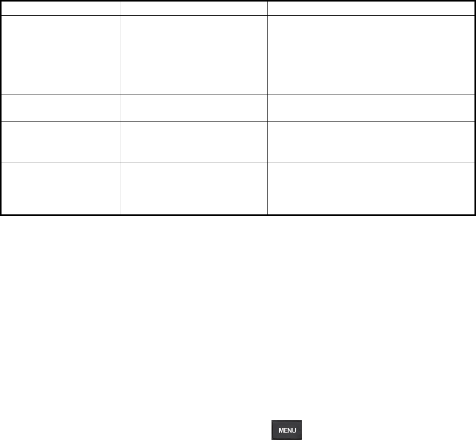
6. MAINTENANCE, TROUBLESHOOTING
6-7
6.7 Diagnostics
A diagnostic test program is provided to test major circuit boards in the control unit,
processor unit and card I/F unit. Note that the normal radar picture is lost during this
test.
Proceed as follows to execute the diagnostic test:
1. Open the [MAIN MENU].
2. Select [INITIAL SETTING], then press the left button.
3. Select [TEST], then press the left button.
4. Select [SELF TEST], then press the left button.
5. To stop the test at any time, press the key.
In a few moments the results of the test are displayed and the buzzer sounds
continuously. The ROMs and RAMs of the SPU, RFC, Control Unit, Trackball Control
Unit and SD CARD readers are checked for proper operation. "OK" appears for
normal operation. If "NG" (No Good) appears, corresponding components may be
defective. Consult your dealer. In the middle of the display the rpm of the antenna unit
and various voltages are displayed.
True motion orientation
not working correctly
1) Incorrect menu setting.
2) Speed entry incorrect
3) TM display inaccurate
1) Referring to section 1.29, select TM
orientation mode.
2) Enter correct own ship speed referring
to section 1.12.
3) Make sure that speed and compass in-
puts are accurate.
Target not tracked cor-
rectly
Poor definition of targets in
sea clutter
Adjust A/C SEA and A/C RAIN referring to
section 1.19 and section 1.20.
Buttons on trackball
module operated but
no response
Trackball module Replace trackball module.
Picture is not updated
with each sweep.
1) Slots in rotating disc in
antenna unit
2) Motor brushes
1) Remove foreign material (carbon,
grease, etc.) from slots.
2) Replace motor brushes if they are
shorter than 6 - 7 mm.
Problem Possible cause Remedy

6. MAINTENANCE, TROUBLESHOOTING
6-8
6.8 Fallback Arrangements
If the top priority sensor (for example GPS1) cannot be used, this equipment
automatically uses the second priority sensor (for example, GPS2) when multiple
sensors (GPS1 and GPS2 for example) are installed. When there is no fallback sensor
available, each function is limited as follows:
Sensor Function limitations
Heading
sensor
• The [HDG] indication reads "***.*°"
• The orientation mode is automatically set to [HEAD-UP].
• TT, AIS, radar map and echo averaging are disabled.
Speed
sensor
When [LOG(WT)] is selected:
• The sensor used is automatically switched in the following priority order: GPS(BT) >
LOG(BT).
• The SPD indication reads "***.* kn" when both GPS(BT) and LOG(BT) cannot be used.
When [LOG(BT)] is selected:
• The sensor used is automatically switched in the following priority order: GPS(BT) >
LOG(WT).
• The SPD indication reads "***.* kn" when both GPS(BT) and LOG(WT) cannot be
used.
When [GPS(BT)] is selected:
• The sensor used is automatically switched in the following priority order: LOG(BT) >
LOG(WT).
• The SPD indication reads "***.* kn" when both LOG(BT) and LOG(WT) cannot be
used.
COG/
SOG
sensor
• When the GPS sensor cannot be used, the values of COG and SOG are calculated
from HDG and LOG(BT).
• Additionally when the heading sensor cannot be used, the values of SOG is calculated
from LOG(BT). The COG indication reads "***.*°".
Position
sensor
• The POSN indication reads all asterisks.
• AIS and radar map are disabled.

APPENDIX 1 MENU TREE
MAIN MENU
├1 ECHO
├2 MARK Default settings are displayed in BOLD ITALIC .
├3 NAVTOOL
├4 ALERT
├5 TT•AIS
├6 FILES (*1) *1:
├7 INFORMATION BOX
├8 NAV LINE•WPT
└9 INITIAL SETTING
1 ECHO
├1 BACK
├2 2ND ECHO REJ (OFF , ON)
├3 TUNE INITIALIZE
├4 PERFORMANCE MON (OFF , ON)
├5 PM ARC (2, 3, 5, 6)
├6 SART (OFF , ON)
├7 ECHO AREA(*2) (CIRCLE , WIDE, ALL, SIMPLE) (*2): Available on non-IMO type only
├8 WIPER (OFF , 1, 2)
├9 ACE ─── ┬
1 BACK
│├2 SIGNAL ENHANCEMENT (1, 2, 3)
│└
3 SUPPRESS SECTOR ─┬1 START (000 º to 359º)
│└
2 ANGLE (000º to 180º)
└0 CUSTOM SELECT ┬1 BACK
├2 CUSTOM1 (OFF , ON)
├3 CUSTOM2 (OFF , ON)
├4 NEAR (OFF , ON)
├5 FAR (OFF , ON)
├6 HEAVY RAIN (OFF , ON)
└7 SHIP (OFF , ON)
2 MARK
├1 BACK
├2 OWN SHIP MARK (MIN , SCALED)
├3 STERN MARK (OFF , ON)
├4 DROP MARK (OFF , ON)
├5 BARG
E
───┬
1 BACK
│├
2 BARGE MARK (OFF , ON)
│├
3 BARGE SIZE ── ┬
1 LENGTH (000 ft , 000 to 999 ft)
│└
4 ARRANGEMENT └2 WIDTH (000 ft , 000 to 999 ft)
├6 INS MARK ── ┬
1 BACK
│├
2 USER CHART (OFF , ON)
│├
3 CURVED EBL (OFF , ON)
│├4 CHART SYMBOL (OFF , ON)
│├
5 NOTE BOOK (OFF , ON, DISPLAY)
│├
6 ROUTE (OFF , CENT, ALL)
│└
7 PREDICTOR (OFF , ON)
├7 RADAR MAP ─┬
1 BACK
│├
2 MARK (OFF, ON )
│├
3 BUOY (OFF, ON )
│├
4 DANGER (OFF, ON )
│├
5 COAST LINE (OFF, ON )
│├
6 CONTOUR LINE (OFF, ON )
│├
7 NAV LINE (OFF, ON )
│└
8 PROHIBITED AREA (OFF, ON )
├8 OWN TRACK ─┬
1 BACK
│├
2 DISP OWN TRACK (OFF , ON)
│├
3 SAVE INTERVAL (OFF, DRAW ONLY , 15 s, 30 s, 1 min, 2 min, 3 min, 6 min, 15 min)
│└
4 OWN TRACK COLOR (RED, GRN, BLU, YEL, CYA, MAG, WHT ) (Non-IMO type only)
This menu item is available when a SD-Card is inserted.
When there is no SD-Card inserted, this item is not selectable.
Continued on next page
AP-1
APPENDIX 1 MENU TREE
├9 DATA DELETE ┬1 BACK
│├
2 MARK ALL DELETE (YES, NO )
│├
3 WPT ALL DELETE (YES, NO )
│└
4 OWN TRACK DELETE(*2) (2POINTS, AREA )(*2) Non-IMO type only
└0 GRID (OFF, ON )
3 NAVTOOL
├1 BACK
├2 PI LIN
E
──── ┬
1 BACK
│├2 PI LINE BEARING(*2) (REL , TRUE) (*2) Non-IMO type only
│├
3 SET ALL PI LINE (1, 2, 3, 6)
│├
4 PI LINE MODE (PARALLEL , PERPENDIC)
│├
5 RESET PI LINE
│├
6 TRUNC RANGE 1 (OFF , ON; 0.000 NM to 24.000 NM)
│└
7 TRUNC RANGE 2 (OFF , ON; 0.000 NM to 24.000 NM)
├3 EBL•VRM•CURSOR(*1) ┬1 BACK (*1) IMO type only
│├
2 EBL OFFSET BASE (STAB GND , STAB HDG, STAB NORTH)
│├
3 VRM TTG (OFF , 1, 2, 1 and 2)
│├
4 VRM OFFSET (OFF , LINK EBL)
│└
5 EBL•CURSOR BEARING (REL , TRUE)
├4 EBL•VRM(*2) ── ┬
1 BACK (*2) Non-IMO type only
│├
2 EBL1 (REL , TRUE)
│├
3 EBL2 (REL , TRUE)
│├
4 VRM1 (REL , TRUE)
│├
5 VRM2 (REL , TRUE)
│├
6 EBL OFFSET BASE (STAB GND , STAB HDG, STAB NORTH)
│├
7 VRM TTG (OFF , 1, 2, 1 and 2)
│├
8 VRM OFFSET (OFF , LINK EBL)
│└
9 CURSOR ── ┬
1 BACK
│├
2 CURSOR BEARING (REL , TRUE)
│├
3 CURSOR RANGE (NM , KM, SM)
│└
4 CURSOR SIZE (SMALL , LARGE)
└5 RANGE RING (OFF, ON )
4 ALERT
├1 BACK
├2 ALERT SOUND LEVEL (OFF, LOW, MID, HIGH )
├3 ANCHOR WATCH (OFF , ON; 0.01 NM to 9.99 NM)
├4 ARRIVAL WPT (OFF , ON; 0 to 999 m)
├5 TARGET ALARM ─┬
1 BACK
│├
2 ALR1 MODE (IN , OUT)]
│├
3 ALR2 MODE (IN , OUT)
│└
4 LEVEL (1, 2, 3, 4)
└6 PRIMARY ALERT ─┬
1 BACK
└
5TT•AIS
├1 BACK
├2 ACQUISITION ZONE ─┬
1 BACK
│├2 AZ STAB (STAB HDG , STAB NORTH)
│├3 AZ POLYGON (OFF , STAB GND, STAB HDG, STAB NORTH)
│└
4 AZ/ALR SWITCH (ACQUISITION ZONE , TARGET ALARM ZONE)
├3 TT•AIS SYMBO
L
── ┬
1 BACK
│├2 SYMBOL COLOR (GRN, BLU, CYA, MAG, WHT )
│├3 ATON SYMBOL COLOR (GRN, BLU, CYA, MAG, WHT )
│├4 AIS ROT TAG LIMIT (000.0 º/min to 720.0º/min)
│├5 TT·AIS PAST POSN POINTS (5, 10)
│└
6 AIS SCALED SYMBOL (OFF , ON)
├4 CPA AUTO ACTIVATE ┬1 BACK
│├2 MAX RANGE (OFF , ON; 00 NM to 99 NM)
│├3 MIN SHIP SPEED (OFF , ON; 1.0 kn to 9.9 kn)
│└
4 EXCEPT CLASS B (OFF , ON)
Continued from previous page
2 TT NEW TARGET, TT LOST, TT TARGET FULL(AUTO), TT TARGET FULL(MAN),
AIS NEW TARGET, AIS LOST, XTE, ARRIVAL, DEPTH, ANCHOR WATCH
Continued on next page
AP-2

APPENDIX 1 MENU TREE
├5 AIS DISP FILTER ─┬
1 BACK
│├2 MAX RANGE (OFF , ON; 00 NM to 99 NM)
│├3 MIN SHIP SPEED (OFF , ON; 1.0 kn to 9.9 kn)
│├4 EXCEPT CLASS B (OFF , ON)
│├5 EXCEPT BASE STATION (OFF , ON)
│├6 EXCEPT PHYSICAL ATON (OFF , ON)
│└
7 EXCEPT VIRTUAL ATON (OFF , ON)
├6 AIS LOST FILTER ─┬
1 BACK
│├2 MAX RANGE (OFF , ON; 00 NM to 99 NM)
│├3 MIN SHIP SPEED (OFF , ON; 1.0 kn to 9.9 kn)
│└
4 EXCEPT CLASS B (OFF , ON)
├7 TT LOST FILTER ─┬
1 BACK
│└
2 MAX RANGE (OFF , ON; 00 NM to 99 NM)
└8 ASSOCIATION ── ┬
1 BACK
├2 ASSOCIATION TGT (OFF , AIS, TT)
├3 GAP (0.000 NM to 0.050 NM)
├4 RANGE (0.000 NM to 0.100 NM)
├5 BEARING (00.0º to 9.9 º)
├6 SPEED (0.0 kn to 6.0 kn)
└7 COURSE (00.0º to 25.0º )
6 FILES* *:
├1 BACK
├2 DRIVE SELECT (SD-1 , SD-2)
├3 SAVE DATA ── ┬
1 BACK
│├2 MARK/LINE ──
┐
│├3 SETTING DATA ─┤
│├4 INSTALL DATA ─┼ ┬1 BACK
│├5 OWN TRACK ─┤ └2 NAME (Software keyboard is displayed for input)
│├6 ALERT HISTOR
Y
─┤
│└
7 LOG FILE ──┘
├4 REPLAY (READ) DATA ┬1 BACK
│├2 MARK/LINE ┐
│├3 SETTING DATA
*
┤
│├4 INSTALL DATA* ┼┬
1 BACK
│└
5 OWN TRACK ┘└
(List of available files is displayed)
├5 DELETE DATA ── ┬
1 BACK
│├2 MARK/LINE ──┐
│├3 SETTING DATA ─┤
│├4 INSTALL DATA ─┼ ┬1 BACK
│├5 OWN TRACK ─┤ └NAME (Software keyboard is displayed for input)
│├6 ALERT HISTOR
Y
─┤
│└
7 LOG FILE ──┘
└6 REMOVE EXTERNAL MEDIA (SD-1, SD-2)
7 INFORMATION BOX
├1 BACK
├2 NAVDATA (OFF , ON)
├3 SET NAVDATA ── ┬
1 BACK
│├2 DEPTH (OFF, ON ; m, ft)
│├3 DEPTH GRAPH SCALE (10 , 20, 50, 100, 200, 500)
│├4 DEPTH MARK (000 TO 500)
│├5 CURRENT (OFF , ON)
│├6 WIND (OFF, ON ; kn, m/s)
│├7 WIND STAB (APPARENT, NORTH , THEORETICAL)
│├8 TEMPERATURE (OFF , ON; ºC , ºF)
│└
9 WPT DATA (OFF , REL, TRUE)
├4 ZOOM (OFF, 2TIMES , 3TIMES)
├5 ZOOM DISPLAY (STAB GND, STAB HDG, STAB NORTH, TT TRACK)
└6 TARGET DATA (1BOX , 2BOX, LARGE)
* (Disabled in TX mode, only available in
STBY mode)
Continued from previous page
This menu item is available when a SD-Card is inserted.
When there is no SD-Card inserted, this item is not selectable.
AP-3
APPENDIX 1 MENU TREE
8 NAV LINE•WPT
├1 BACK
├2 NAV LINE DATA SOURCE (OFF , EXT DATA, WPT MARK)
├3 NAV LINE WIDTH (0.00 NM to 9.99 NM)
├4 WPT SET ─┬
1 BACK
│├2 WPT NO. SELECT (01 to 98, default BLANK )
│├3 WPT NAME (*1) (15 chars max , default BLANK )
│├4 WPT L/L
│└
5 CLEAR DATA (YES, NO )
├5 WPT LIST ─┬
1 BACK
│└
0 NEXT
├6 DISP WPT NO. (OFF , ON)
└7 DISP WPT NAME (OFF , ON)
9 INITIAL SETTING
├1 BACK
├2 OPERATION ┬1 BACK
│├2 WHEEL DRIVE
│├3 KEY BEEP
│├4 OWN SHIP VECTOR
│├5 STERN UP RM
│├6 GUIDANCE (*2) (*2): Available on non-IMO type only
│├7 SHUTTLE FERRY
│└
8 POINTING DEVICE
├3 FUNCTION KEY ┬1 BACK
│├2 F1 ┬1 BACK
││├2 ECHO ──┬
1 BACK
│││└
│││
│││
│││
││├3 STD KEY ─┬
1 BACK
│││└
│││
│││
│││
││├4 TT•AIS ──┬
1 BACK
│││└
││
│
││├─┬
1 BACK
│││└
│││
││└
6 OPERATION ┬1 BACK
││ └
││
│├3 F2 (same as F1, default AUTO-SEA )
│└
4 F3 (same as F1, default ACE HIGH SENSTIVITY )
│
└4 TEST ──── ┬
1 BACK
├2 SELF TEST
└3 TT TEST
2 ECHO AREA, ECHO COLOR, RING(ON/OFF), ZOOM,
MOB, ALARM1, ALARM2, TLL, MAP ALIGN
2 TT-DISP, AIS-DISP, PAST POSN INTERVAL, REF MARK,
CPA LIMIT, CPA, TCPA, AZ1, AZ2, AIS SCALED SYMBOL
2 ALERT ACK, STBY TX, EBL OFFSET, ORIENTATION-
MODE, CU-TM RESET, VECTOR TIME, VECTOR MODE,
TARGET LIST, BRILL, MARK CURSOR, MARK-OS, MENU,
RANGE UP, RANGE DOWN, ACQ, TARGET DATA, TARGET
CANCEL
2 CUSTOM-MENU, IR, ES, EAV, NOISE REJ, ANT
SELECT, PULSE LENGTH, AUTO-SEA, AUTO-RAIN, TUNE
SELECT, 2ND ECHO REJ, PM, SART, ECHO TRAIL, TRAIL
T/R, WIPER, ACE, ACE HIGH SENSITIVITY
2 MARK DELETE, MARK ALL DELETE, OWN TRK DELETE,
OWN TRK ALL DELETE
5 DELETE
DATA
(*1) Software keyboard is
displayed for input.
AP-4
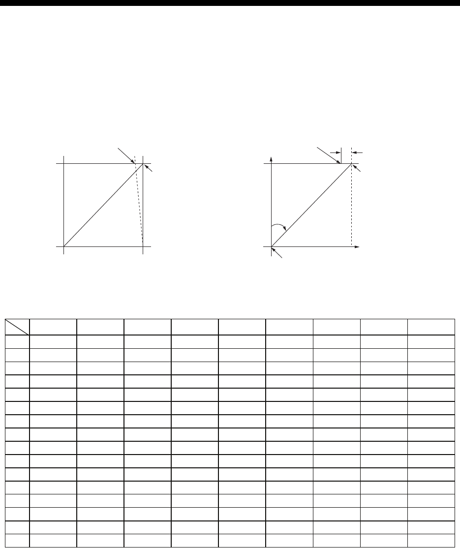
AP-5
APPENDIX 2 LONGITUDE ERROR
TABLE (96 NM SCALE)
The longitude lines concentrate on the north pole and south pole, namely, 1 nm is equivalent to 1
minute at 0 degree latitude, 2 minutes at 60 degrees latitude, 3 minutes at 70 degrees latitude and
so on. For this reason, a longitude error occurs on the radar display.
For example, when own ship is at 60°N and 135°E, even if the cursor indication is 62°N and 139°E,
the real cursor position is deviated to the left (west) side. The table below shows the longitude
error, represented from 0° to 90° at 96 nm from the radar center (own ship).
62°N °N
60°N
135°E
°E
96 nm
q
Real cursor position
Cursor position
indicated
139°E
LAT
Real cursor position
R: Error
Cursor position
indicated
OS position
0.2256 0.4444 0.6496 0.8350 0.9950 1.1248 1.2202 1.2786 1.2980
0.21980213 0.43290201 0.632803 0.8134132 0.96923215 1.09551918 1.1884382 1.24517456 1.26402037
0.21229339 0.41810678 0.61115946 0.78556318 0.93600295 1.05790007 1.14755221 1.20224625 1.22034042
0.20316898 0.40012949 0.58486463 0.75173456 0.89565021 1.0122297 1.09793265 1.15016811 1.16737294
0.19249832 0.37910698 0.55411863 0.71218478 0.84848102 0.95885565 1.03998717 1.08933651 1.10552105
0.18036264 0.35519924 0.51915545 0.66721485 0.79485438 0.89818413 0.97406698 1.02021439 1.03525547
0.16685429 0.32858822 0.48024119 0.61716701 0.73517843 0.83067689 0.90076355 0.94332783 0.95711098
0.15207608 0.29947644 0.437672 0.56242216 0.66990732 0.7568477 0.82060477 0.85926197 0.87168229
0.13614047 0.26808546 0.39177186 0.53339693 0.59953781 0.67725844 0.73420069 0.76865661 0.77961957
0.11916876 0.2346542 0.3428901 0.44054055 0.52460545 0.59251483 0.6422089 0.67220131 0.68162348
0.10129001 0.19943707 0.29139874 0.37433139 0.44568053 0.50326182 0.54532952 0.57063015 0.57843983
0.08264056 0.16270211 0.23768966 0.30527334 0.36336372 0.41017869 0.44429984 0.46471615 0.47085389
0.06336208 0.12472888 0.18217162 0.23389198 0.27828148 0.31397386 0.33988878 0.35526538 0.35968447
0.04360137 0.0858064 0.12526714 0.16073056 0.19108136 0.21537949 0.23289096 0.24311083 0.24577764
0.02350833 0.04623087 0.0674093 0.08634588 0.10242699 0.11514595 0.1241207 0.12910605 0.13000029
0.00323737 0.0063035 0.00903844 0.01130406 0.01299309 0.01403609 0.0144058 0.0141187 0.01323356
75°
70°
65°
60°
55°
50°
45°
40°
35°
30°
25°
20°
15°
10°
5°
0°
5
°
10
°
15
°
20
°
25
°
30
°
35
°
40
°
45
°
LAT
q
(nm)

APPENDIX 2 LONGITUDE ERROR TABLE (96 NM SCALE)
AP-6
1.2780 1.2192 1.1233 0.9933 0.8332 0.6479 0.4431 0.2249 0
1.24442563 1.18701379 1.09356117 0.96694117 0.81103484 0.3061092 0.43117887 0.21881975 0
1.20131324 1.14577786 1.05546143 0.93315023 0.78260251 0.60843159 0.41596331 0.21107193 0
1.14905813 1.09582188 1.00932899 0.89225746 0.74821409 0.58162173 0.397582 0.20171772 0
1.08805799 1.03752602 0.95551494 0.84457408 0.70813132 0.55038538 0.37617487 0.19082831 0
1.0187708 0.97133397 0.89442885 0.79046297 0.66265924 0.51496026 0.35190481 0.17848659 0
0.94174265 0.89774948 0.82653562 0.73033596 0.61214392 0.47561599 0.32495654 0.16478648 0
0.85754099 0.81733258 0.75235195 0.66465066 0.55696981 0.43265198 0.29553516 0.14983224 0
0.76681293 0.73069528 0.63744242 0.59390696 0.49755683 0.38639524 0.26386458 0.13373769 0
0.67024897 0.63849695 0.58741521 0.51864327 0.43435714 0.33719779 0.23018583 0.11662531 0
0.568584 0.54143927 0.49791741 0.43943239 0.36785173 0.28543407 0.19475522 0.09862535 0
0.46259176 0.44026091 0.40463016 0.35687717 0.29854675 0.23149802 0.15784242 0.07987479 0
0.35307892 0.3357319 0.30826343 0.2716059 0.22696965 0.17580013 0.11972833 0.06051633 0
0.2487894 0.22864776 0.20955062 0.18426754 0.15366517 0.1187643 0.08070304 0.0406973 0
0.12684572 0.11982348 0.10624302 0.09552679 0.0791912 0.04106355 0.04106355 0.02056855 0
0.01184713 0.01008727 0.008104 0.00605903 0.00411455 0.00111154 0.00111154 0.00028325 0
75°
70°
65°
60°
55°
50°
45°
40°
35°
30°
25°
20°
15°
10°
5°
0°
50
°
55
°
60
°
65
°
70
°
75
°
80
°
85
°
90
°
LAT
q
(nm)

AP-7
APPENDIX 3 ALERT CODES,
MESSAGES AND MEANINGS
This radar can output alerts in ALF format or ALR format. The output format is set at installation.
A qualified FURUNO technician is required to change the output format.
Alerts are displayed at the bottom right of the screen with the title of the alert and the alert code.
The ALF format outputs a four or five-digit alert code and the ALR format outputs a three-digit
code. The tables below show the alert ID, title, priority, category, meaning and the remedy for each
alert.
For ALF format alerts, the alert identifier (the first three digits of the alert code), is displayed on the
alert list and the alert instance (the last one or two digits of the alert code), is transferred along
with it's identifier to the connected Bridge Alert Management System. The table below shows the
full code for ALF formats alerts, with the instance separated by a comma.
ALF format alerts
Alert
ID Alert title Priority &
Category Message and meaning
190,1 TARGET CAPACITY Caution
Cat: A
Message: "TT TARGET 95%(AUTO)"
Meaning: Automatically acquired target capacity has
reached 95%.
Remedy: Press the ALERT ACK key. Remove TT symbols manually.
190,2 TARGET CAPACITY Warning
Cat: A
Message: "TT TARGET FULL(AUTO)"
Meaning: Automatically acquired target capacity has
reached 100%.
Remedy: Press the ALERT ACK key. Remove TT symbols manually.
190,3 TARGET CAPACITY Caution
Cat: A
Message: "TT TARGET 95%(MAN)"
Meaning: Manually acquired target capacity has
reached 95%.
Remedy: Press the ALERT ACK key. Remove TT symbols manually.
190,4 TARGET CAPACITY Warning
Cat: A
Message: "TT TARGET FULL(MAN)"
Meaning: Manually acquired target capacity has
reached 100%.
Remedy: Press the ALERT ACK key. Remove TT symbols manually.
190,5 TARGET CAPACITY Caution
Cat: A
Message: "AIS DISPLAY 95%"
Meaning: AIS display capacity has reached 95%
(285 targets).
Remedy: Press the ALERT ACK key. Adjust [AIS DISP FILTER] settings to decrease the number
of targets displayed.
190,6 TARGET CAPACITY Warning
Cat: A
Message: "AIS DISPLAY FULL"
Meaning: AIS display capacity has reached 100%
(300 targets).
Remedy: Press the ALERT ACK key. Adjust [AIS DISP FILTER] settings to decrease the number
of targets displayed.
190,8 TARGET CAPACITY Caution
Cat: A
Message: "AIS CAPACITY FULL"
Meaning: AIS capacity has reached 100% (1000
targets).
Remedy: Press the ALERT ACK key. Adjust [AIS DISP FILTER] settings to decrease the number
of targets displayed.

APPENDIX 3 ALERT CODES, MESSAGES AND MEANINGS
AP-8
190,9 TARGET CAPACITY Caution
Cat: A
Message: "AIS ACTIVATE 95%"
Meaning: Active AIS target capacity has reached
95% (38 targets).
Remedy: Press the ALERT ACK key. Adjust [AIS DISP FILTER] settings to decrease the number
of targets displayed.
190,10 TARGET CAPACITY Warning
Cat: A
Message: "AIS ACTIVATE FULL"
Meaning: Active AIS target capacity has reached
100% (40 targets).
Remedy: Press the ALERT ACK key. Adjust [AIS DISP FILTER] settings to decrease the number
of targets displayed.
191,1 CPA/TCPA Alarm
Cat: A
Message: "TT COLLISION"
Meaning: TT is within CPA/TCPA threshold, danger
of collision.
Remedy: Press the ALERT ACK key. Take evasive action if necessary. Adjust CPA/TCPA settings.
191,2 CPA/TCPA Alarm
Cat: A
Message: "AIS COLLISION"
Meaning: AIS target is within CPA/TCPA
threshold, danger of collision.
Remedy: Press the ALERT ACK key. Take evasive action if necessary. Adjust CPA/TCPA settings.
192,1 NEW TARGET Warning
Cat: A
Message: "TT NEW TARGET"
Meaning: A new TT target has entered the
Acquisition Zone.
Remedy: Press the ALERT ACK key. Confirm location of new target.
192,2 NEW TARGET Warning
Cat: A
Message: "AIS NEW TARGET"
Meaning: A new AIS target has entered the
Acquisition Zone.
Remedy: Press the ALERT ACK key. Confirm location of new target.
193,1 LOST TARGET Warning
Cat: A
Message: "TT LOST"
Meaning: TT target is lost.
Remedy: Press the ALERT ACK key. Lost target indication (blinking in red) is removed.
193,2 LOST TARGET Warning
Cat: A
Message: "REF TARGET LOST"
Meaning: REF targets is lost.
Remedy: Press the ALERT ACK key. Lost target indication (blinking in red) is removed.
193,3 LOST TARGET Warning
Cat: A
Message: "AIS LOST"
Meaning: AIS target is lost.
Remedy: Press the ALERT ACK key. Lost target indication (blinking in red) is removed.
194,1 SYSTEM ERROR Warning
Cat: B
Message: "HEADLINE"
Meaning: Heading signal interrupted/lost.
Remedy: Press the ALERT ACK key. Restore signal or rectify reason for signal loss.
194,2 SYSTEM ERROR Warning
Cat: B
Message: "AZIMUTH"
Meaning: Azimuth signal is interrupted/lost.
Remedy: Press the ALERT ACK key. Restore signal or rectify reason for signal loss.
194,3 SYSTEM ERROR Warning
Cat: B
Message: "TRIGGER"
Meaning: Output trigger interrupted/lost
Remedy: Press the ALERT ACK key. Restore signal or rectify reason for signal loss.
194,4 SYSTEM ERROR Warning
Cat: B
Message: "VIDEO"
Meaning: Video signal interrupted/lost.
Remedy: Press the ALERT ACK key. Restore signal or rectify reason for signal loss.
194,5 SYSTEM ERROR Warning
Cat: B
Message: "KEY"
Meaning: Control unit signal interrupted/lost.
Remedy: Press the ALERT ACK key. Restore signal or rectify reason for signal loss.
Alert
ID Alert title Priority &
Category Message and meaning

APPENDIX 3 ALERT CODES, MESSAGES AND MEANINGS
AP-9
194,6 SYSTEM ERROR Warning
Cat: B
Message: "PM COMM ERROR"
Meaning: PM communication error.
Remedy: Press the ALERT ACK key. Restore signal or rectify reason for signal loss.
194,7 SYSTEM ERROR Warning
Cat: B
Message: "TUNE ERROR"
Meaning: TUNE error due to faulty settings or
malfunction.
Remedy: Press the ALERT ACK key. Restore signal or rectify reason for signal loss.
485,1 DEPTH Warning
Cat: B
Message: "DEPTH"
Meaning: Depth is below set threshold.
Remedy: Press the ALERT ACK key. Confirm depth. Adjust [DEPTH] settings as required.
495,1 ANCHOR WATCH Warning
Cat: B
Message: "ANCHOR WATCH"
Meaning: Ship position outside set anchor watch
zone.
Remedy: Press the ALERT ACK key. Confirm Own Ship location and adjust as necessary.
540,1 AIS MSG Caution
Cat: B
Message: "TRANSMIT ERROR"
Meaning: Unable to transmit AIS binary message.
Remedy: Press the ALERT ACK key. Check power to AIS unit.
540,2 AIS MSG Caution
Cat: B
Message: "AIS TRANSMITTING"
Meaning: Transmitting AIS message.
Remedy: Press the ALERT ACK key. No other action required.
560,1 ASSOCIATION Caution
Cat: B
Message: "ASSOCIATION"
Meaning: One or more sets of associated targets is
displayed.
Remedy: Press the ALERT ACK key. Set [ASSOCIATION] to [OFF].
601,1 SENSOR ERROR Warning
Cat: B
Message: "GYRO"
Meaning: No heading information received from
gyrocompass for five seconds.
Remedy: Press the ALERT ACK key. Match the on-screen indication with the actual gyrocompass.
The indication “HEADING SET” appears. Press the ALERT ACK key to erase the indication.
601,2 SENSOR ERROR Warning/
Caution
Cat: B
Message: "LOG(WT)"
Meaning: No speed data received for five seconds
when [LOG(WT)] is set as speed reference.
Remedy: Press the ALERT ACK key. Check SDME sensor. Use a different sensor if necessary.
601,3 SENSOR ERROR Warning/
Caution
Cat: B
Message: "LOG(BT)"
Meaning: No speed data received for thirty seconds
when [LOG(BT)] is set as speed reference.
Remedy: Press the ALERT ACK key. Check SDME sensor. Use a different sensor if necessary.
601,4 SENSOR ERROR Warning
Cat: B
Message: "EPFS"
Meaning: EPFS Error. No speed or position data
received from EPFS device for thirty seconds.
Remedy: Press the ALERT ACK key. Restore the signal. This indication cannot be erased if the
position signal is missing. The indication is automatically removed when the signal is restored.
601,5 SENSOR ERROR Warning
Cat: B
Message: "DATUM"
Meaning: DTM sentence no received for thirty
seconds or erroneous data received.
Remedy: Press the ALERT ACK key. Use the WGS-84 datum.
601,6 SENSOR ERROR Warning
Cat: B
Message: "UTC"
Meaning: UTC error. No date or time data received
for thirty seconds. No ZDA sentence input.
Remedy: Press the ALERT ACK key. Restore the signal to remove this indication.
Alert
ID Alert title Priority &
Category Message and meaning