Furuno USA 9ZWRTR101 Transceiver for Radar model FAR-1518/1528 User Manual OME 36380 A
Furuno USA Inc Transceiver for Radar model FAR-1518/1528 OME 36380 A
Contents
- 1. Installation Manual Part 3
- 2. Installation Manual Part 1
- 3. Installation Manual Part 2
- 4. Installation Manual Part 4
- 5. Installation Manual Part 5
- 6. Installation Manual Part 6
- 7. User Manual Part 1
- 8. User Manual Part 2
- 9. User Manual Part 3
- 10. User Manual Part 4
- 11. User Manual Part 5
- 12. User Manual Part 6
User Manual Part 3

1. OPERATIONAL OVERVIEW
1-40
On-screen menu box operation
1. Select the operational display area, then press the right button. The [CURSOR]
context menu is displayed.
2. Select [EBL OFFSET], then press the left button.
3. Select the operational display area, then press the left button. The EBL line is at-
tached to the cursor.
4. Place the offset EBL on the target appearing as threatening, then press the left
button.
5. After waiting for a few minutes (at least 3 minutes), operate the EBL used in step
1 until it bisects the target at the new position (A1). The EBL readout shows the
target ship's course, which can be true or relative depending on the EBL bearing
reference setting.
6. To return the EBL origin to the own ship's position, repeat steps 1 and 2, then
press the right button.
7. Close the menu.
1.33.2 How to set the point of reference origin point for EBL OFFSET
The origin point of the offset EBL can be ground stabilized (geographically fixed), north
stabilized (true) or referenced to own ship’s heading (relative).
1. Open the [MAIN MENU].
2. Select [NAVTOOL], then press the ADJUST knob.
3. For IMO radars, select [EBL•VRM•CURSOR], then press the ADJUST knob.
For non-IMO radars, select [EBL•VRM], then press the ADJUST knob.
4. Select [EBL OFFSET BASE], then press the ADJUST knob.
5. Rotate the ADJUST knob to select [STAB GND], [STAB HDG] or [STAB NORTH]
as appropriate, then press the ADJUST knob.
6. Close the menu.
• [STAB GND]
• [STAB HDG]
• [STAB NORTH]
: Reference to latitude and longitude. Origin position is always
fixed regardless of your ship's movement.
: Reference to heading. The relationship between origin
position and own position is kept always.
: Reference to North. The origin position changes with North
position.
1. OPERATIONAL OVERVIEW
1-41
1.34 How to Measure Range and Bearing Between
Two Targets
Note: This function requires the [VRM OFFSET] to be set as [LINK EBL]. The [EBL
OFFSET] function must also be assigned to a function key
How to link EBL to VRM OFFSET
1. Open the [MAIN MENU].
2. Select [NAVTOOL], then press the ADJUST knob.
3. Select [EBL•VRM•CURSOR], then press the ADJUST knob.
4. Select [VRM OFFSET], then press the ADJUST knob.
5. Select [LINK EBL], then press the ADJUST knob.
6. Close the menu.
How to measure range and bearing from the control unit
1. Press the EBL OFFSET function key, then use the touchpad to place the origin of
EBL1, for example, on a target of interest. (Shown as “Target 1” in the above ex-
ample).
Note: If there is no EBL displayed when the EBL OFFSET function key is pressed,
EBL1 is automatically displayed.
2. Using the ADJUST knob, move the EBL until it passes through another target of
interest. (Shown as “Target 2” in the above example).
3. Press the key, then rotate the ADJUST knob until the range marker on the
EBL is on the inside edge of Target 2. The active VRM readout at the
lower-right corner of the screen indicates the distance between the two targets.
4. You can repeat the same procedure on third and fourth targets (shown as “Target
3” and “Target 4” in the above example) by using the No. 2 EBL and the No. 2
VRM.
Bearing is shown relative to own ship with suffix "R" or as a true bearing with suffix "T"
depending on EBL relative/true settings in the [EBL•VRM] menu. To return the EBL
origin to the screen center, press the EBL OFFSET function key again.
000 010 020
030
040
050
060
070
080
090
100
110
120
130
140
150
160
170
180
190
200
210
220
230
240
250
260
270
280
290
300
310
320
330
340 350
EBL
origin
R2
Target 2
No.1
EBL
No. 2
EBL
Range
Marker
EBL1
EBL2
>140.0
°
R<
335.2
°
R
VRM1
VRM2
>0.50NM<
0.98NM
Range
Marker
Target 4
Target 3
Target 1
Range/bearing between targets 1 and 2
Range/bearing between targets 3 and 4

1. OPERATIONAL OVERVIEW
1-42
How to measure range and bearing from the on-screen box menu
1. Select the operational display area, then press the right button. The [CURSOR]
context menu is displayed.
2. Select [EBL OFFSET], then press the ADJUST knob.
3. Place the offset EBL on the target of interest (Target 1), then press the ADJUST
knob.
4. Select the [VRM1] box, then press the ADJUST knob.
5. Rotate the ADJUST knob until the range marker on the EBL aligns with Target 2.
The active VRM readout at the lower-right corner of the screen indicates the
distance between the two targets.
6. You can repeat the same procedure on third and fourth targets (shown as “Target
3” and “Target 4” in the above example) by using the No. 2 EBL and the No. 2
VRM.
Bearing is shown relative to own ship with suffix "R" or as a true bearing with suffix "T"
depending on EBL relative/true settings in the [EBL•VRM] menu. To return the EBL
origin to the screen center, move the cursor to the [EBL] box, then press and hold the
left button.
1. OPERATIONAL OVERVIEW
1-43
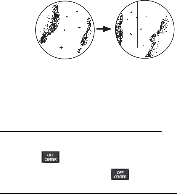
1.35 How to Off-Center the Display
Own ship position, or sweep origin, can be displaced to expand the view field without
switching to a larger range scale. The sweep origin can be off-centered to the cursor
position, but not more than 75% of the range in use; if the cursor is set beyond 75%
of the range scale, the sweep origin will be off-centered to the point of 75% of the limit.
This feature is not available on the 96 nm range or in the true motion mode.
If the conning position is outside the effective radar display, some parts of the bearing
scale are not shown. For details, see section 1.47.
How to off-center the display from the control unit
1. Place the cursor at the position where you wish to move the sweep origin.
2. Press the key. The sweep origin is now off-centered at the cursor position.
3. To cancel off-centering, press the key again.
How to off-center the display from the on-screen menu
1. Place the cursor at the position where you wish to move the sweep origin.
2. Press the right button to show the [CURSOR] menu.
3. Select [OFF CENTER], then press the ADJUST knob.
4. To cancel [OFF CENTER], press the right button.
Note: When the conditions shown below are met, off-center cannot be canceled. This
is because the radar antenna position is located at a position greater than 75% of the
effective radar display.
• Own ship marker is large.
• The distance between antenna position and conning position is large.
• Short-distance display range.
To cancel the off-center, select a larger range, then cancel the off-center.
Off-centered displayPut cursor where desired
and do appropriate
off-center procedure.
Cursor
Cursor
1. OPERATIONAL OVERVIEW
1-44
1.36 Target Trails
The trails of the radar echoes of targets can be displayed
in the form of synthetic afterglow. Target trails are shown
either relative or true and can be sea or ground
stabilized. True motion trails require a compass signal,
and position and speed data. When the range is
changed, trails are continued for targets which were al-
ready
displayed in the previous range. Newly detected targets
have no trail when first detected.
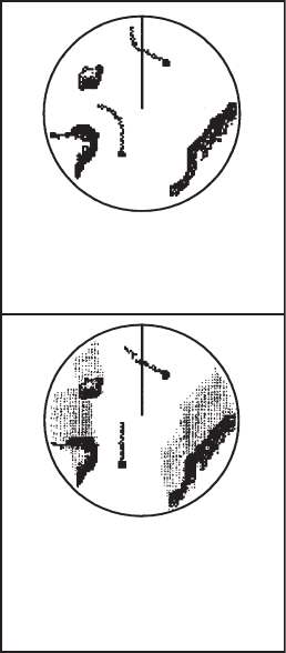
1.36.1 True or relative trails
You can display echo trails in true or relative motion.
Relative trails show relative movements between targets
and own ship. True motion trails present true target
movements in accordance with their over-the-ground
speeds and courses.
Note 1: The [TRAIL MODE] box is shown in yellow
under following conditions:
• [TRAIL MODE] is set to [TRUE] and presentation
mode is set to [HEAD UP RM].
• [TRAIL MODE] is set to [TRUE] and presentation mode is set to [STERN UP].
The reference for the past position displays for AIS and TT is also switched whenever
trail reference is switched.
Note 2: The [TRAIL MODE] box is shown in cyan under the following conditions:
• [TRAIL MODE] is set to [TRUE] and presentation mode is set to [STAB HEAD UP
RM].
• [TRAIL MODE] is set to [TRUE] and presentation mode is set to [COURSE UP RM].
• [TRAIL MODE] is set to [TRUE] and presentation mode is set to [NORTH UP RM].
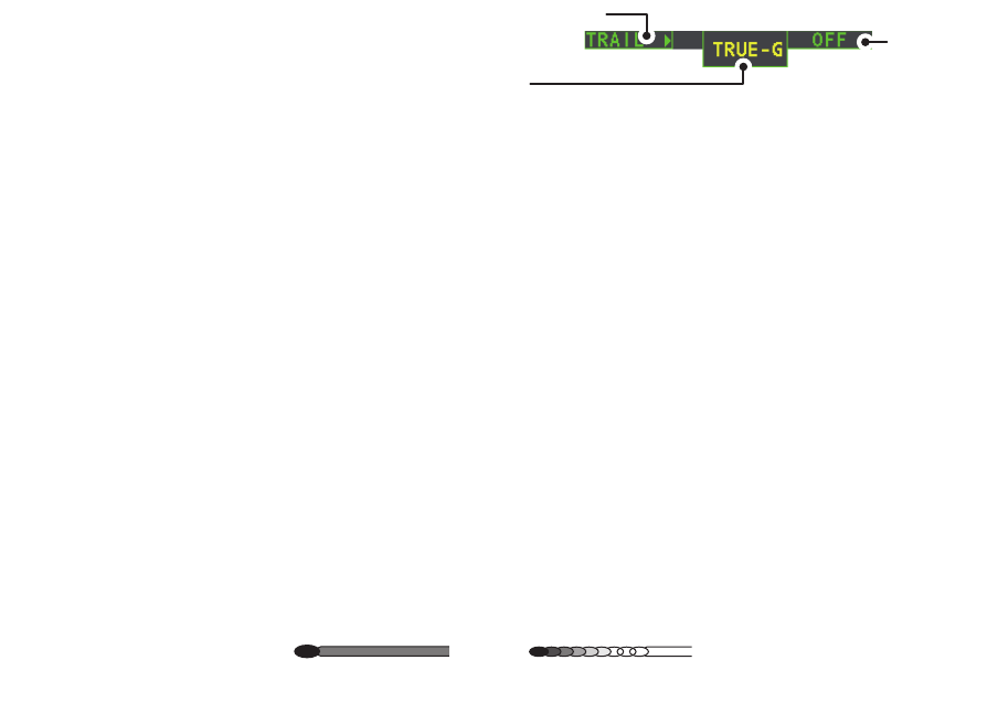
1. Select the [TRAIL] box at the bottom-right of the screen, then press the right
button. The [TRAIL MENU] is displayed.
2. Select [TRAIL MODE], then press the ADJUST knob.
3. Referring to the figure on the right, select the appropriate trail mode, then press
the ADJUST knob.
4. Close the menu.
True target trails -
Stationary targets
are not smeared.
Relative target trails -
Targets move relative
to own ship, stationary
targets are smeared.
1. OPERATIONAL OVERVIEW
1-45
1.36.2 Trail time
Trail time is the interval at which the trail is plotted on-screen. You can adjust the trail
time as follows:
1. Place the cursor on the trail time setting inside the [TRAIL] box at the bottom-right
corner of the screen, then press the left button or the TGT TRAIL key to cycle
through and select the desired setting.
The options, in order, are: [OFF] [15 sec] [30 sec] [1 min] [3 min]
[6 min] [15 min] [30 min] [CONT] [OFF]...
When using the ADJUST knob or the scrollwheel on the RCU-030 to change the trail
time, the time is changed in 30 second increments.
Note 1: The timer displays the elapsed time of the selected trail. Use caution when
using this feature, as the displayed time is not the overall trail time. Also, when the trail
timer is displayed, the trail accuracy of other ship’s echoes may be lowered. When the
trail time reaches the preset interval, the timer disappears.
Note 2: The [CONT] option sets the trail time plotting as continuous. When the plotting
time reaches 29:59, the timer is hidden. The timer reappears when [TRAIL ALL
CLEAR] is selected, or when the range is adjusted.
1.36.3 Trail gradation
The trail afterglow can be displayed in a single tone or with gradual shading.
1. Select the [TRAIL] box at the bottom-right corner of the screen, then press the
right button to display the [TRAIL MENU].
2. Select [TRAIL GRAD], then press the ADJUST knob.
3. Select [Single] or [Multi] (Multiple) as appropriate, then press the ADJUST knob.
4. Close the menu.
1.36.4 Trail level
The level, or intensity, of the afterglow that extends from radar targets can be selected
as below.
1. Select the [TRAIL] box at the bottom-right corner of the screen, then press the
right button to display the [TRAIL MENU].
2. Select [TRAIL LEVEL], then press the ADJUST knob.
3. Select the appropriate setting, then press the ADJUST knob. The higher the
number, the greater the intensity of the afterglow.
4. Close the menu.
Trail time
setting
Trail menu
Displayed as: “TRUE-S”, “TRUE-G” or “REL”.
S: Sea stablized, G: Ground stabilized, REL: Relative
Multiple
(Gradual shading)
Single
(Monotone shading)

1. OPERATIONAL OVERVIEW
1-46
1.36.5 Narrow Trails
Target trails can be painted with thinner lines if desired. This can be useful when there
are a lot of targets on the screen and it is hard to distinguish one from another.
1. Select the [TRAIL] box at the bottom-right corner of the screen, then press the
right button to display the [TRAIL MENU].
2. Select [NARROW TRAIL], then press the ADJUST knob.
3. Select the appropriate setting from [OFF], [1] or [2], then press the ADJUST knob.
[2] is thinner than [1].
4. Close the menu.
1.36.6 How to hide the trails temporarily
Following the procedure outlined in "Trail time" on page 1-45, set the trail time to
[OFF]. The trails are hidden from view, but are continued. To show the trails again,
repeat the procedure, setting the trail time to any interval other than [OFF].
1.36.7 Trail stabilization in true motion
True motion trails can be ground stabilized or sea stabilized. The [TRAIL] box shows
current stabilization as "TRUE-G" or "TRUE-S". To change stabilization mode, open
the [SHIP SPEED MENU] menu and set [SHIP SPEED] to [LOG(BT)] (ground
stabilization) or [LOG(WT)] (sea stabilization).
1.36.8 How to erase/restart trails
All trails can be erased (including those in the memory) and restarted to start fresh
trails.
To erase trails, select the [TRAIL] box, then press and hold the left button or the TGT
TRAIL key.
1.36.9 How to prevent sea clutter in true trails
You can prevent the display of sea clutter in true trails about your ship to clear the
radar picture. Your ship's trails can also be shown or hidden.
1. Select the [TRAIL] box at the bottom-right corner of the screen, then press the
right button to display the [TRAIL MENU].
2. Select [OS TRAIL], then press the ADJUST knob.
3. Select [OFF], [1] or [2] as appropriate, then press the ADJUST knob.
4. Close the menu.
Option Show own ship’s trail Prevent sea clutter in true trails
[OFF] No No
[1] Yes Yes
[2] No Yes
1. OPERATIONAL OVERVIEW
1-47
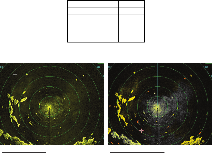
1.37 Target Analyzer
The target analyzer function is designed to analyze echoes and assist the operator to
determine dangerous targets. This function is particularly useful under heavy rain/
snow or where there is surface reflection, which can cause interference and noise.
The target analyzer function can also place hatching over heavy rain areas, reducing
the visible interference and allowing a clearer view of potential targets.
Echoes are displayed in five different colors to assist the operator in identifying
targets. The colors and their respective echoes are shown in the table below.
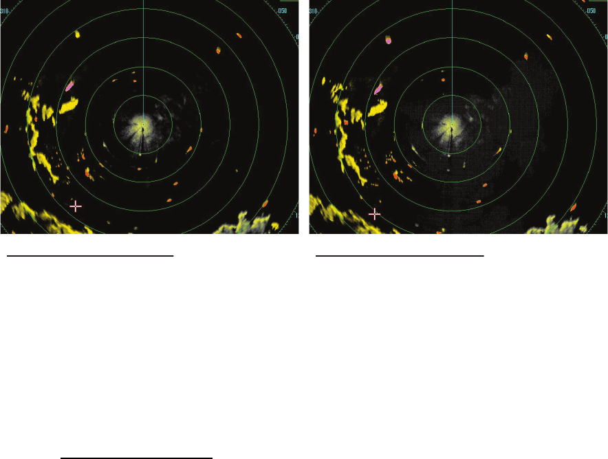
The following example figures show the manner in which this function affects
displayed echoes.
Echo Color
Surface reflection Green
Rain Gray
Moving target Red
Approaching target Pink
Other echoes Yellow
No echo adjustment
(Target analyzer off, EAV off, hatching off)
Rain, moving targets and surface reflections
are all displayed with no filtering.
Minimal echo adjustment
(Target analyzer on, EAV off, hatching off)
Echoes are colored, surface reflections are
filtered, rain is displayed.
1. OPERATIONAL OVERVIEW
1-48
Note 1: This function works best when the settings for [GAIN], [STC], [RAIN], [NOISE
REJECT] and [VIDEO CONTRAST] are properly adjusted (Surface reflections are
displayed in green and rain is displayed in gray).
Note 2: This function recognizes moving targets as approaching targets. Buoys and
other stationary objects are not recognized as approaching targets by this function.
What is “hatching”?
Where echo averaging may hide light rain on the display, the hatching feature, when
activated, places a gray “veil” over the areas where rain is detected. This allows the
operator to see where the rain is without affecting the quality of the displayed echoes.
1.37.1 How to activate/deactivate the target analyzer
1. Select the [CUSTOMIZE ECHO] box, then press the right button.
2. Select [TARGET ANALYZER], then press the ADJUST knob.
3. Select [OFF] to deactivate the function, or [ON] to activate the function, then press
the ADJUST knob.
4. Select [HATCHING], then press the ADJUST knob.
5. Select [OFF] to deactivate the function, or [ON] to activate the function, then press
the ADJUST knob.
6. Close the menu.
Maximum echo adjustment
(Target analyzer on, EAV on, hatching on)
Echoes are colored, surface reflections are
filtered, rain is displayed in gray colored
hatching.
Moderate echo adjustment
(Target analyzer on, EAV on, hatching off)
Echoes are colored, surface reflections and
rain are filtered.
1. OPERATIONAL OVERVIEW
1-49
1.38 Target Alarm
The target alarm serves to alert the navigator to targets (ships, landmasses, etc.)
entering a specific area, with audiovisual alerts.
The target alarm zone has a fixed width of 0.5 nm in the radial direction (depth) and is
adjustable from 3.0 to 6.0 nm (target alarm zone 1) and any distance (target alarm
zone 2). On the Non-IMO radar the boundaries can be set at any distance. On any
radar type the sector of the zone can be set from 0 to 360 degrees in any direction.
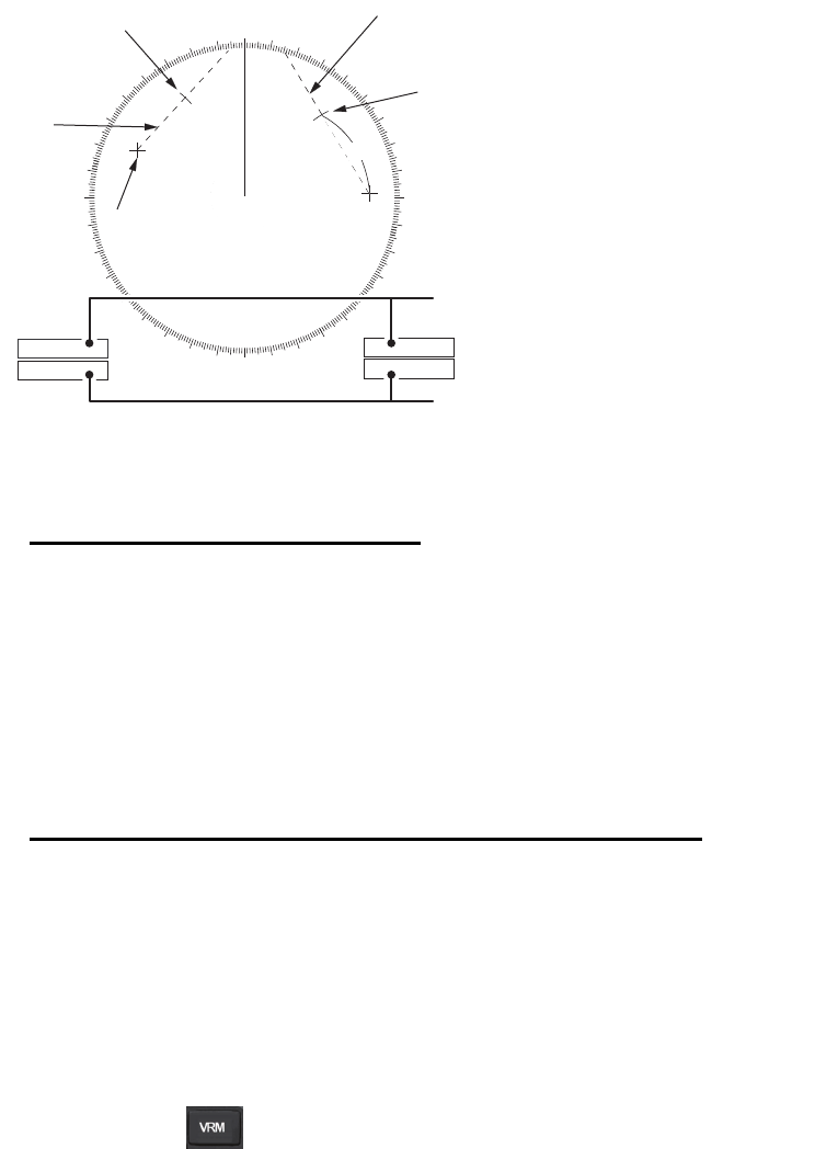
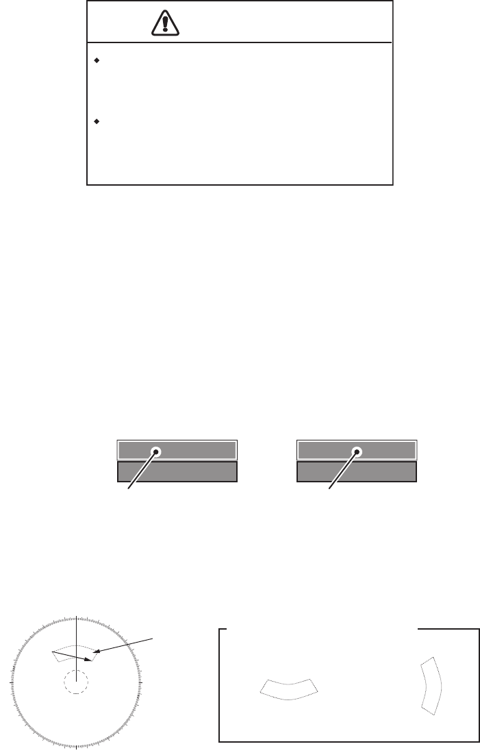
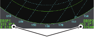
1.38.1 How to set a target alarm
The procedure below shows how to set a target alarm using the figure below as an
example.
1. Place the cursor in the [ALR1] or [ALR2] box as appropriate, then press the left
button. The cursor jumps into the operational display area and the indication
"SET" appears inside the target alarm box selected.
2. Using the touchpad, move the cursor to Point A, then press the left button.
3. Using the touchpad, move the cursor to Point B, then press the left button.
“SET” is replaced with “WORK” in the [ALR1] box indication. The target alarm
zone’s lines are shown as dashed lines.
Note 1: To create a 360° alarm zone, set Point B at the same location as Point A.
Note 2: Two alarm zones can be set simultaneously. The second alarm zone is only
available when the first alarm zone is active, however.
Note 3: When the target alarm zone is not within the range in use the indication "UP
RNG" appears to the right of the target alarm box. In this case select a range that will
display the target alarm zone.
CAUTION
CAUTION
The alarm should not be relied upon as the
sole means for detecting possible collision
situations.
A/C SEA, A/C RAIN and GAIN controls
should be properly adjusted to be sure the
alarm system does not overlook target
echoes.
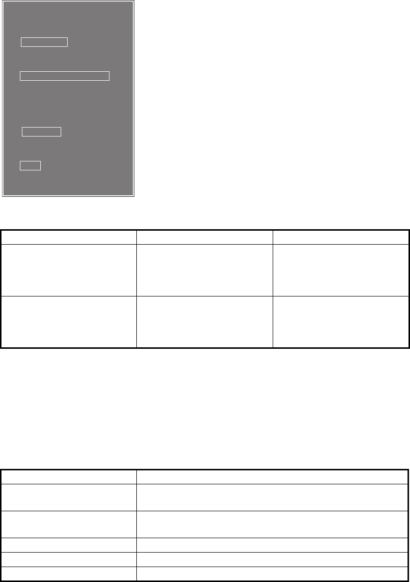
ALR1 OFF
ALR2 OFF
ALR1 SET
ALR2 OFF
ALR1 selected and highlighted ALR1 ready to be set
X
X
X
X
000 010 020
030
040
050
060
070
080
090
100
110
120
130
140
150
160
170
180
190
200
210
220
230
240
250
260
270
280
290
300
310
320
330
340 350
AB
Target
alarm
zone
Other alarm zone examples
Point A
Point A
Point B
Point B

1. OPERATIONAL OVERVIEW
1-50
1.38.2 How to mute the target alarm
A target in the target alarm zone produces both visual (flashing) and audible (beep)
alarms. To silence the audio alarm press the key or select the appropriate
target alarm box then press the left button. The target alarm box indication shows
"ALR MUTE". This will deactivate the audio alarm but will not stop the flashing of the
offending target. To reactivate the audio alarm, press the ALERT ACK key again or
select the target alarm box then press the left button.
When an external buzzer is connected, the audio alarm does not stop until the alarm
zone itself is deactivated. The target alarm box shows "ALR WORK".
1.38.3 How to deactivate a target alarm
Select the target box to be deactivated, then press and hold the left button.
Note: When both [ALR1] and [ALR2] are active, [ALR2] must be deactivated before
[ALR1] can be deactivated.
1.38.4 How to change target alarm attributes
You can select the echo strength level that triggers the alarm, the condition that
generates the alarm and the volume of the audio alarm as follows:
1. Open the [MAIN MENU].
2. Select [ALERT], then press the ADJUST knob.
3. Select [TARGET ALARM], then press the ADJUST knob.
4. Select [ALR1 MODE] or [ALR2 MODE] as appropriate, then press the ADJUST
knob.
5. Select [IN] or [OUT] as appropriate, then press the ADJUST knob.
[IN]: Targets entering the alarm zone trigger the alarm.
[OUT]: Targets leaving the alarm zone trigger the alarm.
6. Select [LEVEL], then press the ADJUST knob.
7. Select the appropriate level of echo strength to trigger the alarm, then press the
ADJUST knob. [1] is the highest strength, [4] is the lowest strength.
8. Press the right button once to return to the [ALERT] menu.
9. Select [ALERT SOUND LEVEL], then press the ADJUST knob.
10. Select [OFF], [LOW], [MID] or [HIGH] as appropriate, then press the ADJUST
knob.
Note: This setting is applied to all alarms output from this radar system.
11. Close the menu.
1. OPERATIONAL OVERVIEW
1-51
1.39 PI (Parallel Index) Lines
PI lines are useful for keeping a constant distance
between own ship and a coastline or a partner ship
when navigating. Up to six sets of PI lines are avail-
able depending on the maximum number of PI lines
selected on the menu.
Max. 1 PI line: Six sets of PI lines (PI1 to PI6)
Max. 2, 3 or 6 PI lines: Four sets of PI lines (PI1 to PI4)
You can control the presentation and interval of the PI
lines from the [PI Line] box, which is at the lower-left
corner of the screen.
1.39.1 How to set the maximum number of lines to display
The maximum number of PI lines to display can be selected from [1], [2], [3] or [6] lines
as below. The actual number of lines visible can be less depending on line
interval.
1. Open the [MAIN MENU].
2. Select [NAVTOOL], then press the ADJUST knob.
3. Select [PI LINE], then press the ADJUST knob.
4. Select [SET ALL PI LINE], then press the ADJUST knob.
5. Select the appropriate option, then press the ADJUST knob.
6. Close the menu.
1.39.2 How to adjust PI line bearing and interval
1. If not already displayed, show a PI line, referring to paragraph 1.39.1.
2. Place the arrow on the PI line orientation in the [PI Line] box.
3. Rotate the ADJUST knob to adjust the PI line bearing, between 000.0° to 359.9°.
Enter a negative value to move the PI line to the opposite side of the PI line pass-
ing through the own ship position.
4. Place the cursor on the PI line interval.
5. Rotate the ADJUST knob to adjust the PI line interval.
PI lines
PI line orientation
PI line interval

1. OPERATIONAL OVERVIEW
1-52
1.39.3 How to change the PI line bearing reference
PI line bearing reference can be relative to own ship’s heading (Relative) or
referenced to North (True) as below.
Note: This function is not available with IMO type radars in this series. The setting is
fixed to [TRUE].
1. Open the [MAIN MENU].
2. Select [NAVTOOL], then press the ADJUST knob.
3. Select [PI LINE], then press the ADJUST knob.
4. Select [PI LINE BEARING], then press the ADJUST knob.
5. Select [REL] or [TRUE] as appropriate, then press the ADJUST knob.
6. Close the menu.
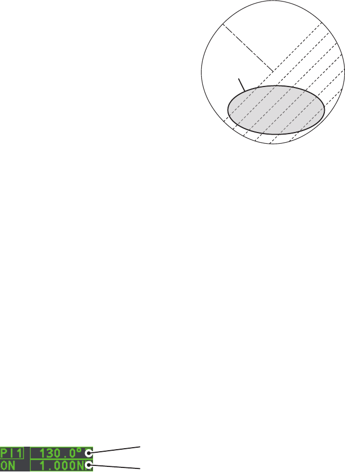
1.39.4 How to change the PI line orientation
PI lines orientation can be selected from parallel or perpendicular. This function is
available when [SET ALL PI LINE] in the [PI LINE] menu is set for other than [1].
1. Open the [MAIN MENU].
2. Select [NAVTOOL], then press the ADJUST knob.
3. Select [PI LINE], then press the ADJUST knob.
4. Select [PI LINE MODE], then press the ADJUST knob.
5. Select [PARALLEL] or [PERPENDIC] as appropriate, then press the ADJUST
knob.
6. Close the menu.
1.39.5 How to reset the PI lines to default (ship’s heading)
You can automatically return PI lines to default orientation (ship’s heading), 0-degrees
for parallel orientation, 90-degrees for perpendicular orientation. This is faster than
doing it manually.
From the PI line box
Place the cursor inside the PI line box, then press and hold the left button.
From the menu
1. Open the [MAIN MENU].
2. Select [NAVTOOL], then press the ADJUST knob.
3. Select [PI LINE], then press the ADJUST knob.
4. Select [RESET PI LINE], then press the ADJUST knob.
5. Select [YES], then press the ADJUST knob.
6. Close the menu.
1. OPERATIONAL OVERVIEW
1-53
1.39.6 How to adjust PI line length
You can adjust the length of the PI lines. This function is only available when [SET ALL
PI LINE] in the [PI LINE] menu is set to [1]. If not already displayed, you can show PI
lines for which you wish to adjust the length by referring to paragraph 1.39.1.
1. Open the [MAIN MENU].
2. Select [NAVTOOL], then press the ADJUST knob.
3. Select [PI LINE], then press the ADJUST knob.
4. Select [TRUNC RANGE 1], then press the ADJUST knob.
5. Select [ON], then press the ADJUST knob.
6. Rotate the ADJUST knob to adjust the front PI line length. The available range is
0.000 NM to 24.000 NM. All PI lines beyond this mark will be hidden.
7. Select [TRUNC RANGE 2], then press the ADJUST knob.
8. Select [ON], then press the ADJUST knob.
9. Rotate the ADJUST knob to adjust the rear PI line length. The available range is
0.000 NM to 24.000 NM. All PI lines beyond this mark will be hidden.
10. To adjust the length of other PI lines, activate the line you wish to adjust, then
repeat steps 1 through 9.
11. Close the menu.
1. OPERATIONAL OVERVIEW
1-54
1.40 Zoom
The zoom function enlarges an area of interest as large as twice the normal viewing
size, in the [INFORMATION BOX]. Zoom can be selected using the control unit or from
a preset function key (See section 1.9 for how to assign functions to the function keys).
Zoom is not available when the [INFORMATION BOX] setting for [TARGET DATA] is
[LARGE].
1.40.1 How to enable/disable the zoom magnification
To enable/disable the zoom magnification, do the following:
1. Open the [MAIN MENU].
2. Select [INFORMATION BOX], then press the ADJUST knob.
3. Select [ZOOM], then press the ADJUST knob.
4. Select the appropriate setting, then press the ADJUST knob.
• [OFF]: Disables the zoom function.
• [2TIMES]: Enables magnification at 2.
• [3TIMES]: Enables magnification at 3.
5. Close the menu.
1.40.2 How to select a zoom area from the control unit
1. Select the operational display area, then press the right button to display the
[CURSOR] context menu.
2. Select [ZOOM], then press the ADJUST knob. The cursor is displayed with a
zoom box when inside the operational display area.
3. Place the cursor and zoom box at the location you wish to zoom, then press the
left button. The cursor returns to normal display, leaving the zoom box at the
selected zoom area.
1.40.3 How to select a zoom area with the function key
When the zoom function is assigned to a function key, the function can be disabled,
or enabled and set, using the function key.
1. Press the ZOOM function key to select the zoom function. The options are
selected in the following cycle: [OFF] [2TIMES] [3TIMES] [OFF]...
The cursor indication changes as shown in paragraph 1.40.2 when [2TIMES] or
[3TIMES] is selected.
2. Place the cursor and zoom box at the location you wish to zoom, then press the
left button. The cursor returns to normal display, leaving the zoom box at the
selected zoom area.
3. To remove the zoom area, press the ZOOM function to cycle through the zoom
settings until the zoom is set to [OFF].
1. OPERATIONAL OVERVIEW
1-55
1.41 How to Use Marks
Select the [MARK] box at the bottom of the screen then
press the right button to open the [MARK] context
menu.
Marks can be entered at any location inside the
operational display area, however, no mark can be
entered at the location of an on-screen box. A total of
5000 marks can be inscribed at any one time.
You can mark any prominent target or a point of partic-
ular interest using the mark feature.
Note: The location and orientation of mark symbols and
mark lines can change, depending on the display
presentation mode, as shown in the table below.
1.41.1 How to select a mark type
1. Select the [MARK] box at the bottom of the screen, then press the right button to
open the [MARK] context menu.
2. Select [MARK KIND], then press the ADJUST knob.
3. Select the appropriate type of marker, referring to the table below, then press the
ADJUST knob.
4. Close the menu.
Presentation mode Mark symbol Mark line
HEAD UP RM/STERN UP
RM/STAB HEAD UP RM
Location is adjusted
according to heading and
own ship position.
Orientation is unchanged.
Location and orientation
are adjusted according to
heading and own ship
position.
COURSE UP RM/NORTH
UP RM/NORTH UP TM
Location is adjusted
according to own ship
position. Orientation is
unchanged.
Location and orientation
are adjusted according to
own ship position.
Mark kind Description
[ORIGIN MARK(No.)] Inscribes the standard origin mark symbol, with mark
number.
[ORIGIN MARK(SYM)] Inscribes the standard origin mark symbol, without mark
number.
[MAP MARK] Inscribes the selected map mark.
[WP1-50] Inscribes waypoint marker 1 through 50.
[WP51-98] Inscribes waypoint marker 51 through 98.
[MARK MENU]
1 ORIGIN MARK
STAB GND / STAB SEA
2 MARK KIND
ORIGIN MARK(No.) /
ORIGIN MARK(SYM) /
MAP MARK /
WP 1~50 /
WP 51~98 /
8 MARK POSITION
CURSOR / OS / L/L
9 MARK COLOR
RED / GRN / BLU / YEL /
CYA / MAG / WHT
0 MAP•MARK MENU
1. OPERATIONAL OVERVIEW
1-56
1.41.2 How to select the mark inscription position
You can select the location at which the marker is inscribed from the following:
1. Select the [MARK] box at the bottom of the screen, then press the right button to
open the [MARK] context menu.
2. Select [MARK POSITION], then press the ADJUST knob.
3. Referring to the table above, select the appropriate location, then press the
ADJUST knob.
How to set the coordinates
Where [MARK POSITION] is set to [L/L], the coordinates settings are displayed.
Coordinates can be set one digit at a time, as shown in the figure below.
1) Rotate the ADJUST knob to adjust the digit, then press the ADJUST
knob to move to the next digit.
2) Repeat step 1 to adjust the Latitude and Longitude as appropriate.
4. Close the menu.
1.41.3 How to select the mark color (for non-IMO types only)
1. Select the [MARK] box at the bottom of the screen, then press the right button to
open the [MARK] context menu.
2. Select [MARK COLOR], then press the ADJUST knob.
3. Select the appropriate color. Available options are shown in the table below.
Location Description
[CURSOR] You can select the location using the touchpad.
[OWN SHIP] Marker is placed at own ship position.
[L/L] Marker is placed at the coordinates selected.
Menu
indication Color Menu
indication Color
RED Red CYA Cyan
GRN Green MAG Magenta
BLU Blue WHT White
YEL Yellow
028º 00.200 N
153º 43.100 E
Currently selected digit is highlighted by the cursor.
Press the ADJUST Rotokey to move to the next digit.
N - North (Latitude)
S - South (Latitude)
W - West (Longitude)
E - East (Longitude)
1. OPERATIONAL OVERVIEW
1-57
1.41.4 How to inscribe marks
You can inscribe marks anywhere inside the operational display area, however, marks
cannot be inscribed in the same location as a menu box.
1. Select the [MARK] box. The [MARK] box is now highlighted.
2. Rotate the ADJUST knob to select the appropriate mark symbol or number.
3. Place the cursor on location (inside the operational display area) you wish to in-
scribe the mark, then press the left button to anchor the mark.
4. Repeat steps 1 to 3 for multiple mark inscription, or press the right button to
complete the procedure.
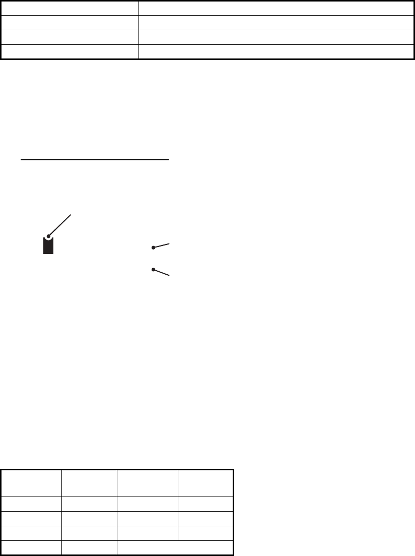
1.41.5 How to use the drop mark
The operator can inscribe a drop mark at a selected location to find the range and
bearing from own ship to the mark. This can be useful for marking a point to avoid
while navigating to a destination.
To active the drop mark feature, do the following:
1. Open the [MAIN MENU].
2. Select [MARK], then press the ADJUST knob.
3. Select [ON] to enable [DROP MARK]. Two indications appear at the bottom of the
screen.
4. Close the menu.
To inscribe a drop mark, follow the procedure outlined in paragraph 1.41.4.
1.41.6 How to set origin mark stabilization
Origin marks can be geographically fixed (ground stabilized) or moving (sea
stabilized).
1. Select the [MARK] box at the bottom of the screen, then press the right button to
open the [MARK] context menu.
2. Select [ORIGIN MARK], then press the ADJUST knob.
3. Select [STAB GND] or [STAB SEA] as appropriate, then press the ADJUST knob.
4. Close the menu.
DROP MARK boxes show mark
number, bearing and range to mark

1. OPERATIONAL OVERVIEW
1-58
1.41.7 How to delete marks
Marks can be deleted one at a time, or all at once.
How to delete marks individually
1. Select the operational display area, then press the right button to show the
[CURSOR] menu.
2. Select [MARK DELETE], then press the ADJUST knob. The cursor changes to a
highlighted cursor.
3. Place the highlighted cursor on the mark to be deleted, then press the ADJUST
knob.
4. Repeat step 3 to delete another mark, or press the right button to return the
cursor to normal function.
How to delete all marks
1. Open the [MAIN MENU].
2. Select [MARK], then press the ADJUST knob.
3. Select [DATA DELETE], then press the ADJUST knob.
4. Select [MARK ALL DELETE], then press the ADJUST knob. A confirmation
message is displayed.
5. Select [YES], then press the ADJUST knob.
6. Close the menu.
1.41.8 How to hide the heading line marker
The heading line is a line from the own ship position to the outer edge of the radar
display area and appears at zero degrees on the bearing scale in HEAD UP mode; it
changes the orientation depending on the ship orientation in NORTH UP and True
Motion modes.
To temporarily extinguish the heading line to look at targets existing dead ahead of
own ship, press the key on the keyboard, or use the touchpad to select the [HL
OFF] box at the left of the display then press the left button. In addition to the heading
line, the stern marker and all graphics within the effective display are also erased. To
redisplay the heading line, etc., release the key or the left button.
1.41.9 How to hide/show the stern mark
The stern marker, which is a dotted line, appears opposite to the heading line. To
display or erase this marker do the following:
1. Open the [MAIN MENU].
2. Select [MARK], then press the ADJUST knob.
3. Select [STERN MARK], then press the ADJUST knob.
4. Select [ON] or [OFF] as appropriate, then press the ADJUST knob.
5. Close the menu.
1. OPERATIONAL OVERVIEW
1-59
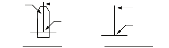
1.41.10 How to set up the own ship symbol
The own ship symbol marks own position on the display. It can be turned on or off and
its configuration selected from the [MARK] menu. Two configurations are available:
minimized symbol and scaled symbol. If the largest dimension of the symbol gets
smaller than 6 mm, the scaled symbol will disappear and the own ship mark will be
shown as a minimized symbol. The scaled symbol is scaled to indicate the length and
beam of the vessel. Ship’s dimensions should be entered at installation to use the
scaled ship symbol.
1. Open the [MAIN MENU].
2. Select [MARK], then press the ADJUST knob.
3. Select [OWN SHIP MARK], then press the ADJUST knob.
4. Select [MIN] or [SCALED] as appropriate, then press the ADJUST knob.
5. Close the menu.
1.41.11 How to use the INS marker
You can receive predicted position data by connecting this radar to an INS.
1. Open the [MAIN MENU].
2. Select [MARK], then press the ADJUST knob.
3. Select [INS MARK], then press the ADJUST knob.
4. Select [PREDICTOR], then press the ADJUST knob.
5. Select [ON], then press the ADJUST knob.
6. Close the menu.
1.41.12 How to show/hide radar map marks
You can show or hide marks on the radar map.
1. Place the cursor on the [MARK] box at the bottom of the screen, then press the
right button to open the [MARK] context menu.
2. Select [MAP DISPLAY], then press the ADJUST knob.
3. Select [ON] or [OFF] as appropriate, then press the ADJUST knob.
4. Close the menu.
Scaled symbol Minimized symbol
Heading line
Beam line
X
Antenna
position
Heading line
Beam line
1. OPERATIONAL OVERVIEW
1-60
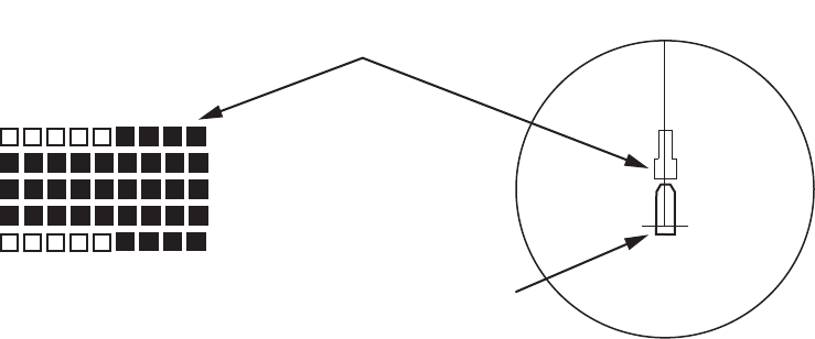
1.41.13 How to set the barge marker
You can mark the locations of barges on the display with icons. Set up barge
information as follows:
1. Open the [MAIN MENU].
2. Select [MARK], then press the ADJUST knob.
3. Select [BARGE], then press the ADJUST knob.
4. Select [BARGE MARK], then press the ADJUST knob.
5. Select [ON] to display barge marks, [OFF] to hide barge marks, as appropriate,
then press the ADJUST knob.
6. Select [BARGE SIZE], then press the ADJUST knob. Use the ADJUST knob to
enter the [LENGTH] and [WIDTH] of the barge.
Rotate the ADJUST knob to increase or decrease the value of the highlighted
digit.
7. Select [ARRANGEMENT], then press the ADJUST knob. This item lets you set a
single barge or a barge chain. Select one of the five arrangements and rotate the
ADJUST knob. Select number of barges (max. 9) to display. As you rotate the
ADJUST knob the squares light or extinguish and the number of barges
selected appears at the right side.
8. Close the menu. The barge mark is now displayed as shown in the figure above.
4
9
9
9
4
X
First row of barge [ARRANGEMENT] is displayed
as the left side of the barge icon on-screen.
Own ship icon

1. OPERATIONAL OVERVIEW
1-61
1.42 How to Adjust Brilliance of On-screen Data
On-screen markers and alphanumeric readout brilliance can be adjusted using the
following procedure:
1. Place the cursor on the [BRILL] box at the right of the screen, then press the right
button. The [BRILL] menu is displayed.
2. Select the appropriate item to adjust, then press the ADJUST knob.
3. Rotate the ADJUST knob to select the appropriate brilliance setting, then press
the ADJUST knob.
4. Close the menu.
1.42.1 How to adjust color palettes
This radar provides six sets of color and brilliance sets to match any ambient lighting
condition and can be assigned to a BRILL box preset.
1. Select the [BRILL] box at the bottom-left of the screen, then press the right
button. The [BRILL] menu is displayed.
2. Select [PALETTE], then press the ADJUST knob.
3. Select the appropriate palette, then press the ADJUST knob. The default settings
for each palette is shown in the table below.
4. Close the menu.
Menu item Description
ECHO COLOR Adjust brilliance of the echo color.
PALETTE Adjust background brilliance (See paragraph 1.42.1).
CONTROL PANEL Adjust brilliance of the control panel keys.
CHARACTER Adjust on-screen text brilliance.
CURSOR Adjust brilliance of the cursor.
ECHO Adjust the echo brilliance.
TRAIL Adjust echo trail brilliance.
HL Adjust heading line brilliance.
RING Adjust range ring brilliance.
BEARING CURSOR Adjust bearing cursor brilliance.
EBL Adjust EBL line brilliance.
VRM Adjust VRM line brilliance.
PI LINE Adjust PI line brilliance.
TT SYMBOL Adjust Target Trail symbol brilliance.
AIS SYMBOL Adjust AIS symbol brilliance.
L/L GRID Adjust Latitude/Longitude grid brilliance.
MARK Adjust brilliance of all marks.
PALETTE BRILL PANEL OTHERS TEXT
COLOR BCKGRND/CIRCLE
DAY-GRY 100 15 15 GREEN GRY/BLK
DAY-BLU 100 15 15 WHITE BLU/BLU
DUSK-GRY 40 10 15 GREEN GRY/BLU
DUSK-BLU 40 10 15 WHITE BLU/BLU
NIGHT-GRY 4 5 15 AMBER GRY/BLK
NIGHT-BLU 4 5 15 WHITE BRT-BLU/BRT-BLU
1. OPERATIONAL OVERVIEW
1-62
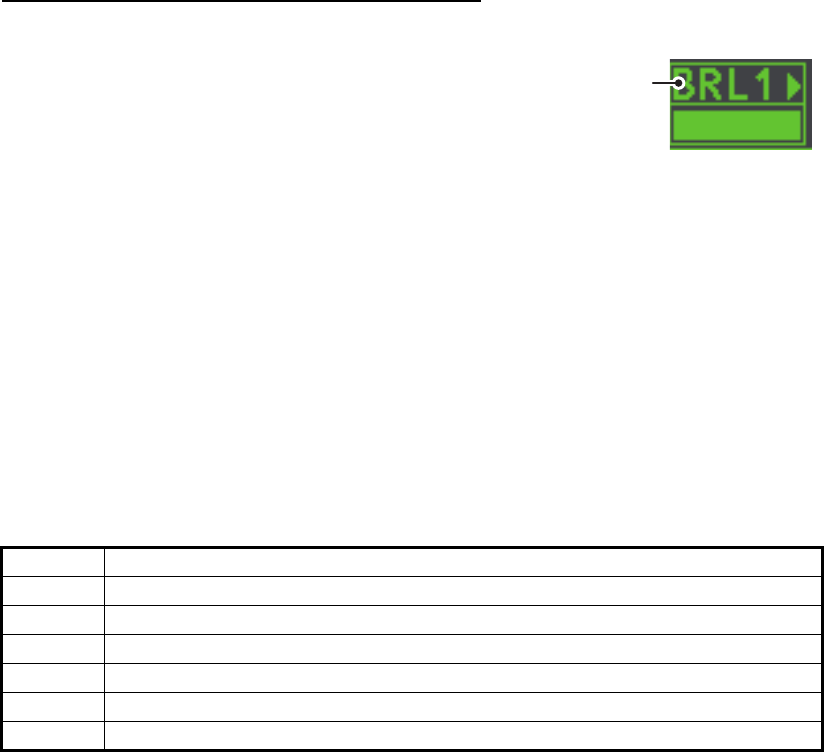
How to assign/change the brilliance presets
1. Place the cursor on the BRL indication inside the [BRILL] box.
2. Press the left button to cycle through the pre-
sets. There are four available: [BRL1],
[BRL2], [BRL3] and [BRL4].
3. To adjust the palette for a preset, press the
right button with the preset selected. The
[BRILL] menu is displayed.
4. Follow steps 2 to 4 in "How to adjust color palettes" on page 1-61.
5. Repeat the process to adjust other presets’ palettes.
1.42.2 How to adjust the echo color
1. Select the [BRILL] box at the bottom-left of the screen, then press the right
button. The [BRILL] menu is displayed.
2. Select [ECHO COLOR], then press the ADJUST knob.
3. Select the appropriate color, then press the ADJUST knob. The available options
are listed in the table below.
Color Description/remarks
YEL Yellow echo (default setting)
GRN Green echo
WHT White echo
AMB Amber echo
M-GRN Red echo, gradually changes to green color as the echo weakens.
M-CYA Red echo, gradually changes to cyan color as the echo weakens.
Place cursor here,
then press the left
button to change
brilliance preset,
right button to open
the [BRILL] menu.

1. OPERATIONAL OVERVIEW
1-63
1.43 How to Display and Set Up Navigational Data
Wind, depth, ocean current, water temperature, date and time and waypoint data can
be displayed on this radar, however appropriate sensors are required.
1.43.1 How to set up the navigational data
1. Open the [MAIN MENU].
2. Select [INFORMATION BOX], then press the ADJUST knob.
3. Select [SET NAV DATA], then press the ADJUST knob.
4. Referring to the table below, select the appropriate menu item, then press the
ADJUST knob.
5. Referring to the available options listed in the table above, select the appropriate
setting, then press the ADJUST knob.
6. Close the menu.
1.43.2 How to display navigational data
1. Open the [MAIN MENU].
2. Select [INFORMATION BOX], then press the ADJUST knob.
3. Select [NAV DATA], then press the ADJUST knob.
4. Select [ON] to display navigational data, [OFF] to hide navigational data, then
press the ADJUST knob.
5. Close the menu.
Menu item Available settings
DEPTH [OFF], [ON] (m, ft)
DEPTH GRAPH SCALE [10], [20], [50], [100], [200], [500] (m)
DEPTH MARK [000] to [500] (m)
CURRENT [OFF], [ON]
WIND [OFF], [ON] (kn, m/s)
WIND STAB [APPARENT], [NORTH], [THEORETICAL]
TEMPERATURE [OFF], [ON] (°C, °F)
WPT DATA [OFF], [REL], [TRUE]
1. OPERATIONAL OVERVIEW
1-64
1.44 How to Use the Information Box
The information box shows target data, navigational data and zoomed areas of the
radar display. To set up the information box, do the following:
1. Open the [MAIN MENU].
2. Select [INFORMATION BOX], then press the
ADJUST knob.
3. Select and set the appropriate menu item, referring
to the table below.
4. Close the menu.
Menu item Settings Description
[NAV DATA] • OFF
• ON
• Disable navigational data display.
• Enable navigational data display.
[SET NAV DATA] See section 1.43 for
details.
Set up the format in which various
navigational data is displayed in the
[INFORMATION BOX].
See section 1.43 for details.
[ZOOM] • OFF
• 2TIMES
• 3TIMES
• Disable zoom magnification.
• Set zoom magnification at 2.
• Set zoom magnification at 3.
[ZOOM DISPLAY] • STAB GND
• STAB HDG
• STAB NORTH
• TT TRACK
• Ground stabilized zoom (Geographically
fixed).
• Heading stabilized zoom (Relative).
• North stabilized zoom (True).
• Tracked targets are zoomed.
[TARGET DATA] • 1BOX
• 2BOX
• LARGE
See figure below.
[INFORMATION BOX]
1 BACK
2 NAV DATA
OFF / ON
3 [SET NAV DATA]
4 ZOOM
OFF / 2TIMES / 3TIMES
5 ZOOM DISPLAY
STAB GND / STAB HDG /
STAB NORTH / TT TRACK
6 TARGET DATA
1BOX / 2BOX / LARGE
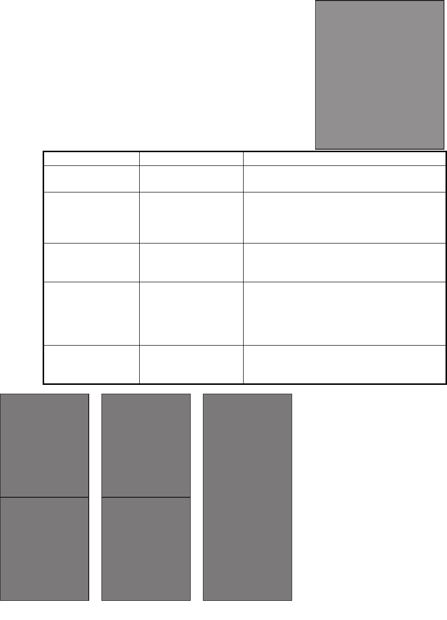
1BOX 2BOX LARGE
Only TT/AIS data
is displayed in the
lower half of the
information box.
Only TT/AIS Data
is displayed in
the large box.
Up to two AIS
targets or up four
TT targets
Zoom and
navigational data
are displayed here.
Zoom and
navigational data
are displayed here,
but can be hidden
by TT/AIS data.
Only TT/AIS data
is displayed in the
lower half of the
information box.
• TT/AIS data displayed in
the information box is
shown in order of
acquisition in the bottom
half of the box.
• When using the 2BOX
setting and the bottom half
of the information box is
full, the upper half is
overlayed with the newly
aquired TT/AIS target data.
• When the target data is no
longer displayed (TT is
cancelled, etc.) in the upper
box, the previous display is
restored.
• Each box may display up
two TT targets or one AIS
target.
1. OPERATIONAL OVERVIEW
1-65
1.45 Interswitch
The interswitch of this
radar uses an Ethernet
to transfer video and
control signals. A digital
signal transfers the video
and control signals. You
can connect two
antennas and two display units. Set radar display and antenna groups from the
[ANTENNA SELECT] display.
When you switch to a different antenna, the heading skew and timing adjustment (set
at installation) for that antenna is automatically applied.
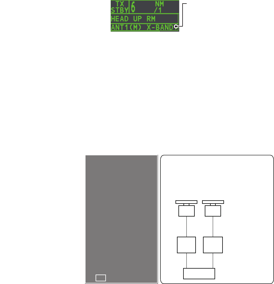
The [ANTENNA] box at the upper left position shows current antenna selection.
1.45.1 How to display antenna information
You can display antenna information by highlighting the [ANTENNA] box, then
pressing the right button. The [ANT SELECT] context menu is displayed.
1.45.2 How to preset antenna and display combinations
You can preset the antenna and display combinations for each antenna and display
in the radar system. As an example, the procedure below shows how to select the no.
1 antenna unit for the no. 2 display unit.
1. Highlight the [ANTENNA] box, then press the right button to open the [ANT
SELECT] menu.
2. Select the display unit for which to select an antenna (at the next step). For
example, select [DISP2] to select the no. 2 display unit.
3. Select [ANT 1] and [M].
4. Repeat steps 2 and 3 to set other display and antenna combinations.
5. Click [STORE INTER-SW] and select [YES] to save your selections.
6. Close the menu.
Antenna box
ANT1 (or ANT2): indicates
antenna selected
(M) or (S): indicates antenna is
(M)aster or (S)lave
X-Band: indicates the antenna
bandwidth
←
←
Using the information displayed in this
example the antenna system
configuration would look something
like this.
Antenna Unit
Processor Unit
ANT1 ANT2
HUB-100
DISP1 DISP2
[ANT SELECT]
ANT1: X -BAND
25UP MAIN - TOP
12 MAIN - 2ND
ANT2: X -BAND
OWN RADAR NO.1
MASTER
MASTER
NO / YES
1 DISP1 ANT1
2 DISP1 ANT2
9 STORE INTER -SW
The following information is
displayed in the [ANT SELECT]
context menu.
• Radar band, output power
and antenna position of each
antenna currently powered. (If
an antenna is not powered, its
data area is blank.)
• Current antenna and display
combinations.

1. OPERATIONAL OVERVIEW
1-66
Antenna selection considerations
Radar Functions Control Master Display Option Slave Display Option
AIS function Independent Desired value can be set Desired value can be set
Brilliance
Echo trails
EBL
Lat/long data
Presentation mode
Speed data
Target alarm
TT, AIS on/off
TT, AIS track interval
Vector mode
Vector time
VRM
Wiper
Zoom
TT COLLISION alarm
Range
(Sampling at Master)
Independent Desired Value can be set
(Echo Sampling at
Master Range)
Desired value can be set
A/C SEA Dependent Control Desired value can be set Cannot control
A/C RAIN
Automatic Clutter
Elimination (ACE)
Gain
IR
Echo stretch
Echo averaging
Picture setting
(Customize echo)
STBY/TX
Tuning
Reference Point
TT LOST warning Common Control Item Commonly
Controlled
Item Commonly
Controlled
TT alerts ACK
TT acquire
TT/AIS AZ
• An antenna unit cannot be controlled from multiple display units. Select one Master display unit for one antenna
unit. If two antenna units are set as masters, the display last-set as master becomes the master and all other
displays are automatically changed to slave.
• An antenna unit without a Master display cannot be selected on the sub display units. If there is no antenna unit
set as master, the lowest number display is automatically set as master.
• If the Alert 740 “EXT RADAR ERROR” appears, do one of the following as applicable:
- If only your antenna is not displayed on the [ANT SELECT] display, the LAN line in the Processor Unit
may be faulty. In this case, use the standalone mode.
- If the antenna that was in use does not appear on the [ANT SELECT] display, the LAN line in other
Processor Unit may be faulty. In this case, see the preceding page for how to select a different antenna unit.
• When the Network fails, the Interswitch does not work, but standalone operation is possible.
• Radar functions are controlled independently, dependently or commonly depending on selection as Master or
Slave (see the table below).

1. OPERATIONAL OVERVIEW
1-67
1.46 Performance Monitor
The performance monitor, installed in the antenna unit, produces a visual indication
on the radar display screen when the radar transmitter power and radar receiver
sensitivity and are within the prescribed limits.
1.46.1 How to activate/deactivate the performance monitor
When the performance monitor is active, the indication "PM" appears (in yellow
characters) inside the [ALERT] box.
Note: If the blind sector and the direction of the PM antenna overlap on another, turn
off the blind sector in order to display echoes correctly.
The radar is automatically set as follows when the performance monitor is activated.
1) Set the radar to TX (transmit) mode.
2) Open the [MAIN MENU].
3) Select [ECHO], then press the ADJUST knob.
4) Select [PERFORMANCE MON], then press the ADJUST knob.
5) Select [OFF] or [ON] as appropriate, then press the ADJUST knob.
6) Close the menu.
Setting Setting at PM
activation
Adjustable
while PM
is active
Setting at PM deactivation
GAIN 70 *1Yes *3Setting before PM activation.
SEA 0 No Setting before PM activation.
SEA AUTO MAN No Setting before PM activation.
RAIN 0 No Setting before PM activation.
RAIN AUTO MAN No Setting before PM activation.
TUNE AUTO No Setting before PM activation.
ACE OFF No Setting before PM activation.
ES OFF No Setting before PM activation.
EAV OFF No Setting before PM activation.
IR 2 No Setting before PM activation.
NOISE REJECT OFF No Setting before PM activation.
VIDEO CONTRAST 4-B No Setting before PM activation.
PULSE LONG No Setting before PM activation.
2ND ECHO REJ OFF Yes Setting at PM deactivation.
LOW LEVEL ECHO Previous setting kept,
fixed.
No Setting before PM activation.
WIPER OFF No Setting before PM activation.
CUSTOMIZE ECHO Previous setting kept,
fixed.
No Return to active display.
PRESENTATION MODE No change. *2Yes Setting at PM deactivation.
RANGE 24 NM, 24 SM, 48 km Yes *4Setting at PM deactivation.
OFF CENTER OFF Yes Setting at PM deactivation.
*1: Gain is automatically set according to [PM GAIN ADJ], if it was adjusted at installation.
*2: [NORTH UP RM] is selected when the [PRESENTATION MODE] is set to [NORTH UP TM].
*3: The setting is not memorized.
*4: The performance monitor is deactivated if the range is changed manually.