Furuno USA 9ZWRTR101 Transceiver for Radar model FAR-1518/1528 User Manual OME 36380 A
Furuno USA Inc Transceiver for Radar model FAR-1518/1528 OME 36380 A
Contents
- 1. Installation Manual Part 3
- 2. Installation Manual Part 1
- 3. Installation Manual Part 2
- 4. Installation Manual Part 4
- 5. Installation Manual Part 5
- 6. Installation Manual Part 6
- 7. User Manual Part 1
- 8. User Manual Part 2
- 9. User Manual Part 3
- 10. User Manual Part 4
- 11. User Manual Part 5
- 12. User Manual Part 6
User Manual Part 4
1. OPERATIONAL OVERVIEW
1-68
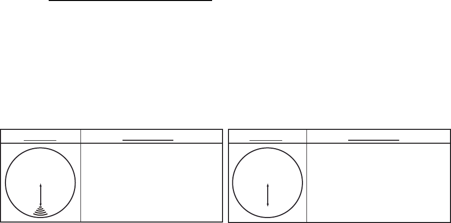
1.46.2 How to check the radar’s performance
The range scale is automatically set to 24 NM. The radar screen will show arcs. If the
radar transmitter and receiver are in good working conditions in as much as the
original state when the monitor was turned on, the innermost arcs should appear
between 8.0 NM to 19.8 NM. The performance monitor can observe a total of 10 dB
loss in transmitter and receiver.
How to set the number of arcs
1. Open the [MAIN MENU].
2. Select [ECHO], then press the ADJUST knob.
3. Select [PM ARC], then press the ADJUST knob.
4. Select [2], [3], [5] or [6] as appropriate, then press the ADJUST knob.
5. Close the menu.
The figure belows shows an example where [PM ARC] is set to [5].
Note 1: The lengths of the arcs can vary according to installation environment. Judge
the strength of the echo that appears within 60° from the arc location to confirm if the
radar is working properly or not.
Note 2: The location of the arcs changes according to the [PM ARC] setting.
Turn the performance monitor off when finished.
8.0 NM to
19.8 NM
8.0 NM to
19.8 NM
Display
Radar State
Display
Transmitter: normal
Receiver: normal
Transmitter and receiver:
No arc indicates 10 dB loss.
Contact your dealer for advice.
(For magnetron radars, have
a technician check the
magnetron.
Radar State
1. OPERATIONAL OVERVIEW
1-69
1.47 How to Adjust the Reference Position
The reference position for measurements (range, bearing, etc.) and markers (heading
line, stern mark, etc.) can be antenna position or consistent common reference point
(CCRP), which is a location on own ship to which all horizontal measurements, for
example range, bearing, relative course, relative speed, closest point of approach
(CPA) or time to closest point of approach (TCPA), are normally referenced.
To adjust the reference position, use the touchpad to place the cursor over the "REF
POINT" indication at the top of the screen, then press the left button to select [ANT]
or [CCRP] as applicable. You can also adjust the reference by rotating the ADJUST
knob when the cursor is placed over the indication.
The position of the own ship marker changes according to reference position as
shown below. If the CCRP is positioned outside of the effective display area, the bear-
ing scale is indicated with the appropriate reduced detail.
Range and bearing are measured and graphics are drawn according to reference
position as in the table below.
Category Item Reference point
ANT CCRP
Range and bearing
measurements
EBL Range and bearing
measured from
antenna position.
Range and bearing
measured from
CCRP.
VRM
Cursor
PI line
Range ring
Drop mark
Graphics Heading line Drawn from
antenna position.
Drawn from CCRP.
Stern mark
Beam line
Own ship vector
Own ship track
Bearing cursor Drawn with antenna
position at center.
Drawn with CCRP
at center.
Course, speed Calculated with
antenna position at
center.
Calculated with
CCRP at center.
CPA, TCPA Calculated with
antenna position at
center.
Calculated with
CCRP at center.
BCR, BCT Calculated from bow position.
Continued on next page
X
CCRP position
X
ANT position
Radar antenna
position is at
center of display
Conning position is at
center of display
1. OPERATIONAL OVERVIEW
1-70
Note: When the antenna is located some distance from the CCRP, the CCRP can be
outside the bearing cursor in true motion or off-center.
Also, when the CCRP is set as reference point, some parts of the bearing cursor are
not displayed.
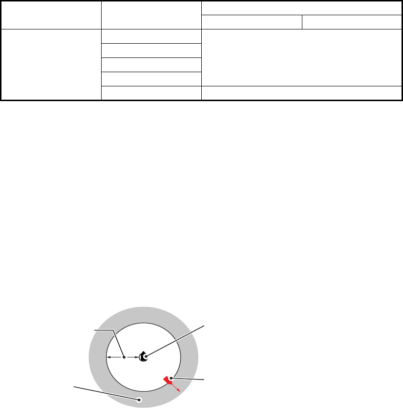
1.48 Anchor Watch
The anchor watch feature alerts you when your ship has traveled a distance greater
than a threshold value, when it should be at rest. When the anchor watch is active, an
orange dashed circle marks the anchor watch range.
If your ship goes outside the circle, the indication "ANCHOR WATCH" appears in the
[ALERT] box.
1. Open the [MAIN MENU].
2. Select [ALERT], then press the ADJUST knob.
3. Select [ANCHOR WATCH], then press the ADJUST knob.
4. Select [ON] to enable [ANCHOR WATCH].
5. Using the ADJUST knob, select the distance for the alert. Press the ADJUST
knob to apply the setting.
6. Close the menu.
Own ship data Heading Data is taken from respective sensors,
regardless of reference point selected.
Speed
Course over ground
Speed over ground
Own L/L Location of the CCRP.
Category Item Reference point
ANT CCRP
A
nchor watch
alarm setting
Own ship location when
anchor watch is set
Own ship moves
outside watch zone
Alarm is
triggered
1. OPERATIONAL OVERVIEW
1-71
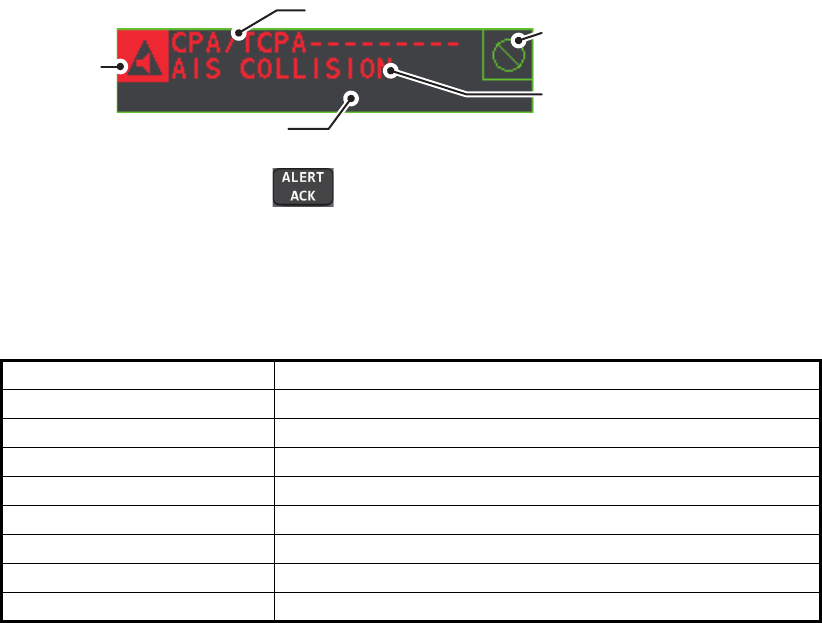
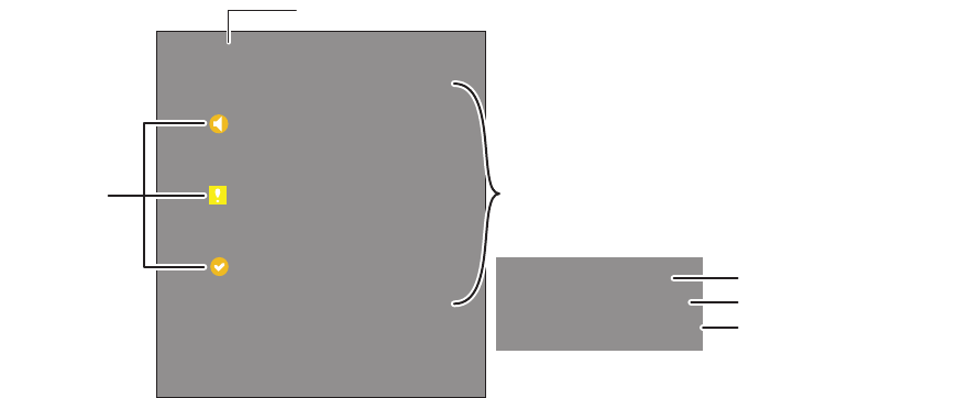
1.49 How to Interpret the ALERT Box
When an alert condition is found, the applicable alert message appears in the [ALERT]
box. A buzzer sounds for alarm and warning alerts. The [ALERT] box is composed of
three lines of information, and two icons, as shown below.
Silence the buzzer with the key or select the [ALERT] box then press the left
button. The buzzer and the flashing stop but the alert indication remains on the
display until the reason for the alert is removed.
Status indications are displayed in yellow text. The displayable indications are listed
in the table below.
1.49.1 Alert descriptions
Alerts which can appear on this radar are listed in the table. The level of priority, from
highest to lowest, is ALARM WARNING CAUTION. For detailed information re-
garding specific alerts and alert codes, including possible remedies, see "ALERT
CODES, MESSAGES AND MEANINGS" on page AP-7.
Note: All active-unacknowledged warnings are repeated as warnings after 60 sec-
onds (manufacturer’s fixed time period).
Status indication Reason for display
AUTO VIDEO ADJ Video adjust ([VIDEO ADJ]) is set to [AUTO].
PM Performance Monitor (PM) is ON.
SART SART is ON.
TUNE INITIALIZE TUNE INITIALIZE is ON.
VIRTUAL AIS ATON:OFF [AIS VIRTUAL ATON] is OFF.
WR CARD DATA Writing data to SD card.
RD CARD DATA Reading data from SD card.
DELETE CARD DATA Deleting data from SD card.
Buzzer silence
icon
Alert description
Alert title
Alert icon
Status indications appear here
1. OPERATIONAL OVERVIEW
1-72
1.49.2 Alert list
The alert list displays the names of violated alerts, including the time and date violated.
Up to 100 alerts are stored in the internal memory. Unacknowledged alarms are
displayed first in the list (in red text), in the order in which they appear in the [ALERT]
box. Unacknowledged warnings are displayed in the list (in yellow-orange text), in the
order in which they appear in the [ALERT] box.
Cautions are displayed in the list (in yellow text), in the order in which they appear in
the [ALERT] box.
An unacknowledged alert can be acknowledged from the list by selecting it, the press-
ing the left button. To erase the data for the number selected, press the left button
again. To erase all alert indications, select [REFRESH DATA], then press and hold the
left button.
To display the alarm list, place the cursor in the [ALERT] box and press the right
button.
To change pages, select Next, then press the left button.
Alert title and code
Alert description
Date and time of alert
Displayed page/Pages available
[ALERT LIST (1/2)]
1 BACK
192 NEW TARGET
TT NEW TARGET
03/APR/2015 06:45
2 190 TARGET CAPACITY
TT TARGET 95% (AUTO)
03/APR/2015 06:50
3 190 TARGET CAPACITY
AIS DISPLAY FULL
03/APR/2015 06:15
9 REFRESH DATA (L=CLEAR)
0 NEXT
Alert icons
192 NEW TARGET
TT NEW TARGET
03/APR/2015 06:45
Alerts are displayed in the same color as their
alert icon.
1. OPERATIONAL OVERVIEW
1-73
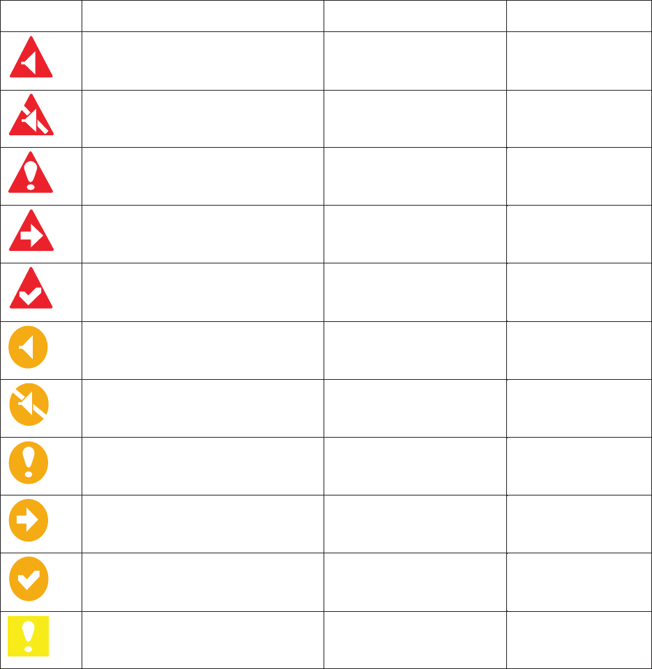
1.49.3 Alert icons and their meanings
1.49.4 How to assign alarm priority to an alert
You can assign the same priority as an alarm to an alert, using the following
procedure.
1. Open the [MAIN MENU].
2. Select [ALERT], then press the ADJUST knob.
3. Select [PRIMARY ALERT], then press the ADJUST knob.
4. Select the alert you wish to assign alarm priority to, then press the ADJUST knob.
Selected items area underlined.
5. Close the menu.
Icon Status Visual indication Audible alert
Active–
unacknowledged alarm
Red, Flashing 3 short audible
alerts repeated
every 7 seconds.
every 60 seconds.
Active –
silenced alarm
Red, Flashing Silent
Active–
acknowledged alarm
tneliSdeR
Active –
responsibility transferred alarm
tneliSdeR
Rectified –
unacknowledged alarm
tneliSdeR
Active –
unacknowledged warning
Yellow-orange, Flashing 2 short audible
alerts repeated
Active –
silenced warning
Yellow-orange, Flashing Silent
Active –
acknowledged warning
Yellow-orange Silent
Active –
responsibility transferred warning
Yellow-orange Silent
Rectified–
unacknowledged warning
Yellow-orange Silent
tneliSwolleYnoituaC
1. OPERATIONAL OVERVIEW
1-74
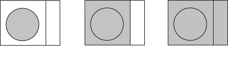
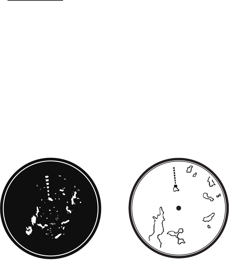
1.50 How to Select a Display Mode
Non-IMO radars in this series have several display options available. For IMO radars
in this series, only the standard display mode is available.
• Standard display mode: The operational display area, box functions, data display,
etc. are shown in a standard (IMO compliant) manner.
• [CIRCLE] mode: The echoes are displayed inside a circle on the screen.
• [WIDE] mode: The echoes are displayed in a square area, but are not displayed in
the data display area.
• [ALL] mode: The echoes are displayed across the entire screen.
• Simple display: The display is echo-focused, menu boxes and the data display are
simplified.
Follow the procedure below to change display modes.
1. Open the [MAIN MENU].
2. Select [ECHO], then press the ADJUST knob. The [ECHO] menu is displayed.
3. Select [ECHO AREA], then press the ADJUST knob.
4. Select the appropriate setting, then press the ADJUST knob.
5. Close the menu.
CIRCLE WIDE ALL
1. OPERATIONAL OVERVIEW
1-75
1.51 How to Manage SD-Card Data
The following data can be stored on a SD-Card: marks, lines, user settings, installation
settings, own track, alert history and some alert logs (for example, the alert log).
1.51.1 How to access the SD-Card menu
Note: This operation is only available when a SD-Card is inserted. When there is no
SD-Card inserted, the [FILES] menu is not selectable.
1. Open the [MAIN MENU].
2. Select [FILES], then press the ADJUST knob.
3. Select [DRIVE SELECT], then press the ADJUST knob.
4. Select [SD-1] or [SD-2] as appropriate, then press the ADJUST knob.
1.51.2 How to save data
1. Access the SD-Card menu as shown in paragraph 1.51.1
2. Using the ADJUST knob, select [SAVE DATA], then press the ADJUST knob.
3. Using the ADJUST knob, select the data to be saved, then press the ADJUST
knob. The software keyboard is displayed.
4. Using the software keyboard, name the file, then select [END]. The file name can
be up to 12 characters in length. The indication "WR CARD DATA" appears during
the save process.
5. Close the menu.
1.51.3 How to read (load) data
1. Access the SD-Card menu as shown in paragraph 1.51.1
2. Using the ADJUST knob, select [REPLAY (READ) DATA], then press the
ADJUST knob.
3. Using the ADJUST knob, select the data to be read, then press the ADJUST
knob. The indication "RD CARD DATA" appears during the read process.
4. Close the menu.
1.51.4 How to delete data
1. Access the SD-Card menu as shown in paragraph 1.51.1
2. Using the ADJUST knob, select [DELETE DATA], then press the ADJUST knob.
3. Using the ADJUST knob, select the data to be deleted, then press the ADJUST
knob. The indication "DELETE CARD DATA" appears during the delete process.
4. Close the menu.
1. OPERATIONAL OVERVIEW
1-76
This page is intentionally left blank.

2-1
2. RADAR OBSERVATION
2.1 General
2.1.1 Minimum and maximum ranges
Minimum range
The minimum range is defined by the shortest distance at which, using a scale of 1.5
or 0.75 nm, a target having an echoing area of 10 m2 is still shown separate from the
point representing the antenna position.
It is mainly dependent on the pulselength, antenna height, and signal processing such
as main bang reduction and digital quantization. It is a good practice to use a shorter
range scale as far as it gives favorable definition or clarity of picture.
The IMO Resolution MSC.192(79) requires the minimum range to be less than 40 m,
respectively. This series of radars satisfy this requirement.
Maximum range
The maximum detecting range of the radar, Rmax, varies considerably depending on
several factors such as the height of the antenna above the waterline, the height of the
target above the sea, the size, shape and material of the target, and the atmospheric
conditions.
Under normal atmospheric conditions, the maximum range is equal to the radar
horizon or a little shorter. The radar horizon is longer than the optical one by about 6%
because of the diffraction property of the radar signal. The Rmax is given in the
following equation.
For example, if the height of the antenna above the waterline is 9 meters and the
height of the target is 16 meters, the maximum radar range is;
It should be noted that the detection range is reduced by precipitation (which absorbs
the radar signal).
R
max
= 2.2 x ( h1 + h2)
where R
max
: radar horizon (nautical miles)
h1: antenna height (m)
h2: target height (m)
Radar horizon
Optical horizon
Rmax = 2.2 x ( 9 + 16) = 2.2 x (3 + 4) = 15.4 nm

2. RADAR OBSERVATION
2-2
X-band and S-band
In fair weather, the equation on the previous page does not give a significant
difference between X- and S-band radars. However, in heavy precipitation condition,
an S-band radar would have better detection than an X-band radar.
Radar resolution
There are two important factors in radar resolution (discrimination): bearing resolution
and range resolution.
• Bearing resolution is the ability of the radar to display as separate pips the echoes
received from two targets that are at the same range and close together. It is
proportional to the antenna length and reciprocally proportional to the wavelength.
The length of the antenna radiator should be selected for a bearing resolution better
than 2.5° (IMO Resolution). This condition is normally satisfied with a radiator of 1.2
m (4 ft) or longer in the X-band. The S-band radar requires a radiator of about 12
feet (3.6 m) or longer.
• Range resolution is the ability to display as separate pips the echoes received from
two targets that are on the same bearing and close to each other. This is determined
by pulselength only. Practically, a 0.08 microsecond pulse offers the discrimination
better than 40 m as do so with all FURUNO radars.
Test targets for determining the range and bearing resolution are radar reflectors
having an echoing area of 10 m2.
Bearing accuracy
One of the most important features of the radar is how accurately the bearing of a
target can be measured. The accuracy of bearing measurement basically depends on
the narrowness of the radar beam. However, the bearing is usually taken relative to
the ship’s heading, and thus, proper adjustment of the heading line at installation is an
important factor in ensuring bearing accuracy. To minimize error when measuring the
bearing of a target, put the target echo at the extreme position on the screen by
selecting a suitable range.
Range measurement
Measurement of the range to a target is also a very important function of the radar.
Generally, there are two means of measuring range: the fixed range rings and the
variable range marker (VRM). The fixed range rings appear on the screen with a pre-
determined interval and provide a rough estimate of the range to a target. The variable
range marker’s diameter is increased or decreased so that the marker touches the
inner edge of the target, allowing the operator to obtain more accurate range
measurements.
2. RADAR OBSERVATION
2-3
2.2 False Echoes
Occasionally echo signals appear on the screen at positions where there is no target
or disappear even if there are targets. They are, however, recognized if you
understand the reason why they are displayed. Typical false echoes are shown below.
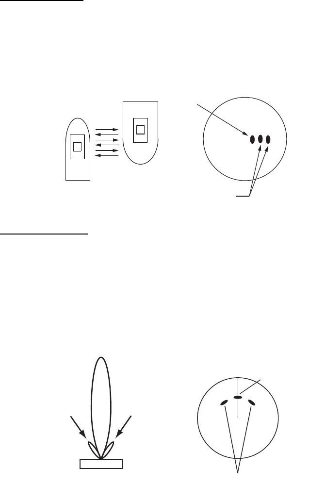
Multiple echoes
Multiple echoes occur when a transmitted pulse returns from a solid object like a large
ship, bridge, or breakwater. A second, a third or more echoes may be observed on the
display at double, triple or other multiples of the actual range of the target as shown
below. Multiple reflection echoes can be reduced and often removed by decreasing
the gain (sensitivity) or properly adjusting the A/C SEA control.
Sidelobe echoes
Every time the radar pulse is transmitted, some radiation escapes on each side of the
beam, called “sidelobes”. If a target exists where it can be detected by the side lobes
as well as the main lobe, the side echoes may be represented on both sides of the true
echo at the same range. Side lobes show usually only on short ranges and from strong
targets. They can be reduced through careful reduction of the gain or proper
adjustment of the A/C SEA control.
Your ship
Target
True
echo
Multiple
echo
True target
Mainlobe (beam)
Antenna
Sidelobe
False echoes by sidelobes
Sidelobe
2. RADAR OBSERVATION
2-4
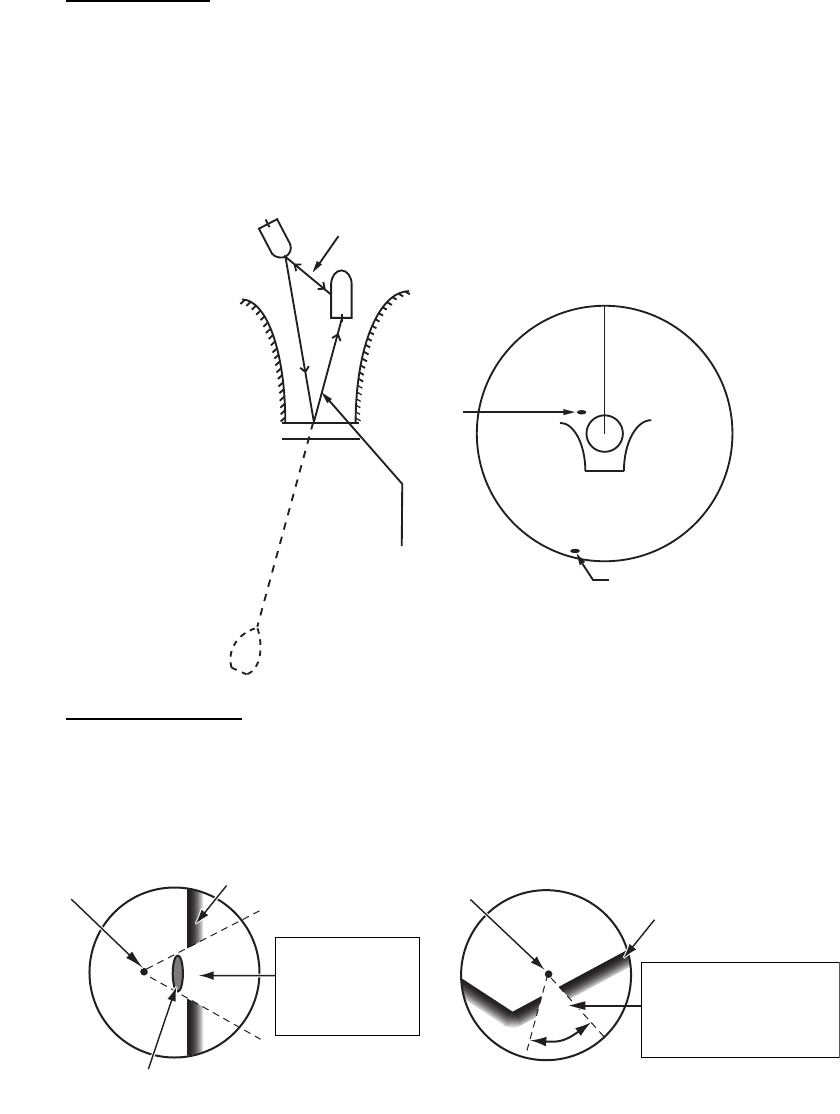
Virtual image
A relatively large target close to your ship may be represented at two positions on the
screen. One of them is the true echo directly reflected by the target and the other is a
false echo which is caused by the mirror effect of a large object on or close to your
ship as shown in the figure below. If your ship comes close to a large metal bridge, for
example, such a false echo may temporarily be seen on the screen.
Shadow sectors
Funnels, stacks, masts, or derricks in the path of the antenna block the radar beam. If
the angle subtended at the antenna is more than a few degrees, a non-detecting
sector may be produced. Within this sector targets can not be detected.
True
echo
False
echo
Your ship
Target ship
Mirror image
of target ship
Bridge
Route for direct reflection
Route for
indirect reflection
Wharf and its echo
Large ship Size of blind sector depends
on size of obstruction and range.
Radar position Radar position
Wharf and its echo
Shadow sector occurs
because obstruction
(like mast) is in path
of radar beam.
Shadow sector
occurs because
wharf is hidden
behind ship.
2. RADAR OBSERVATION
2-5
2.3 SART (Search and Rescue Transponder)
2.3.1 SART description
A Search and Rescue Transponder (SART) can be triggered by any X-Band (3 cm)
radar within a range of approximately 8 nm. Each radar pulse received causes it to
transmit a response which is swept repetitively across the complete radar frequency
band. When interrogated, it first sweeps rapidly (0.4 s) through the band before
beginning a relatively slow sweep (7.5 s) through the band back to the starting
frequency. This process is repeated for a total of twelve complete cycles. At some
point in each sweep, the SART frequency will match that of the interrogating radar and
be within the pass band of the radar receiver. If the SART is within range, the
frequency match during each of the 12 slow sweeps will produce a response on the
radar display, thus a line of 12 dots equally spaced by about 0.64 nautical miles will
be shown.
When the radar to the SART is reduced to about 1 nm, the radar display my show also
the 12 responses generated during the fast sweeps. These additional dot responses,
which also are equally spaced by 0.64 nautical miles, will be interspersed with the
original line of 12 dots. They will appear slightly weaker and smaller than the original
dots.
Radar antenna
beamwidth
Screen A: When SART is distant Screen B: When SART is close
Echo from SART
Position of
SART
Your ship
position Your ship
position
SART mark
length
24 NM 1.5 NM
Position of
SART
Echo from
SART
Lines of 12 dots are displayed in
concentric arcs.

2. RADAR OBSERVATION
2-6
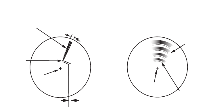
2.3.2 How to show SART marks on the radar display
This radar is equipped with a feature that optimally sets up the radar for SART
detection. This feature automatically detunes the radar receiver out of its best tuning
condition. This erases or weakens all normal radar echoes, but the SART marks are
not erased because the SART response signal scans over all frequencies in the 9 GHz
band. When the radar approaches the SART in operation, the SART marks will
enlarge to large arcs, blurring a large part of the screen.
1. Open the [MAIN MENU].
2. Select [ECHO], then press the left button.
3. Select [SART], then press the left button.
4. Select [ON] to show SART marks on the radar display, then press the left button.
Select [OFF] to hide SART marks.
When the SART function is active, the following setting changes are automatically
made to radar functions:
5. Close the menu.
The indication "SART" appears at the bottom of the alert box, in yellow text, when this
feature is active. Be sure to turn this feature off when SART detection is no longer your
objective.
2.3.3 General remarks on receiving SARTs
SART range errors
When responses from only the 12 low frequency sweeps are visible (when the SART
is at a range greater than about 1 nm), the position at which the first dot is displayed
can be as much as 0.64 nm beyond the true position of the SART. When the range
closes so that the fast sweep responses are seen also, the first of these will be no
more than 150 meters beyond the true position.
Radar bandwidth
This is normally matched to the radar pulselength and is usually switched with the
range scale and the associated pulselength. Narrow bandwidths of 3-5 MHz are used
with long pulses on long range scales and wide bandwidths of 10-25 MHz with short
pulses on short ranges.
A radar bandwidth of less than 5 MHz will attenuate the SART signal slightly, so it is
preferable to use a medium bandwidth to ensure optimum detection of the SART.
Setting Changed to
Range 12 NM
Pulselength Long
Echo Stretch Off
Noise Rejector Off
Echo Averaging Off
Interference Rejector Off
Performance Monitor Off
A/C RAIN Off
2. RADAR OBSERVATION
2-7
Radar side lobes
As the SART is approached, side lobes from the radar antenna can show the SART
responses as a series of arcs or concentric rings. These can be removed by the use
of the anti-clutter sea control although it can be operationally useful to observe the
side lobes as they may be easier to detect in clutter conditions and also they will
confirm that the SART is near to own ship.
Note: SART information excerpted from IMO SN/Circ 197 OPERATION OF MARINE
RADAR FOR SART DETECTION.
2.4 RACON
A RACON is a radar beacon that emits radar receivable signals in the radar frequency
spectrum (X- or S-band). There are several signal formats; in general, the RACON
signal appears on the radar screen as a rectangular echo originating at a point just
beyond the position of the radar beacon. It has a Morse coded pattern. Note that the
position on the radar display is not accurate.
2.5 Radar Target Enhancer (RTE)
An RTE is a radar transponder is mounted on navigation buoys and masts of small
crafts to significantly improve their detection by radar. Unlike a SART or RACON,
which are passive, the RTE receives a radar signal, amplifies it and re-transmits it,
with the intention of making the target's signal look larger on a radar display. The RTE
is available in X-band and S-band types.
Echo description
RACON signalRACON signal RACON stationRACON station
Echoes on the radar screen
Your ship positionYour ship position
2. RADAR OBSERVATION
2-8
This page is intentionally left blank.
3-1
3. TARGET TRACKING (TT)
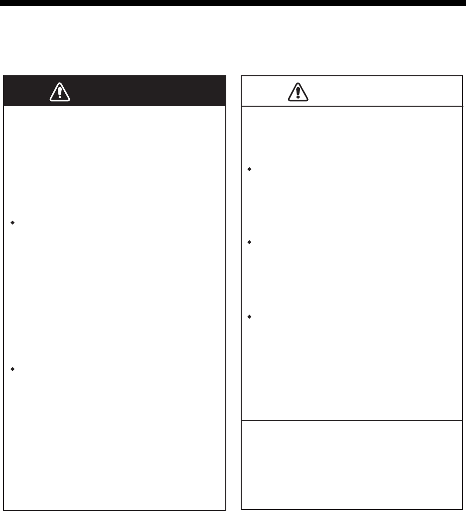
3.1 Precautions for Target Tracking Usage
WARNINWARNINGCAUTIOCAUTION
No one navigational aid should be relied
upon for the safety of vessel and crew.
The navigator has the responsibility to
check all aids available to confirm
position. Electronic aids are not a
substitute for basic navigational
principles and common sense.
This TT automatically tracks automatically or
manually acquired radar targets and
calculates their courses and speeds,
indicating them by vectors. Since the data
generated by the auto plotter are based on
what radar targets are selected, the radar
must always be optimally tuned for use with
the auto plotter, to ensure required targets
will not be lost or unwanted targets such as
sea returns and noise will not be acquired
and tracked.
A target does not always mean a land-mass,
reef, ships or other surface vessels but can
imply returns from sea surface and clutter.
As the level of clutter changes with
environment, the operator should properly
adjust the A/C SEA, A/C RAIN and GAIN
controls to be sure target echoes are not
eliminated from the radar screen.
The plotting accuracy and response of
this TT meets IMO standards. Tracking
accuracy is affected by the following:
The data generated by TT, AIS and
video plotter are intended for
reference only.
Tracking accuracy is affected by course
change. One to two minutes is required to
restore vectors to full accuracy after an
abrupt course change. (The actual amount
depends on gyrocompass specifications.)
The amount of tracking delay is inversely
proportional to the relative speed of the
target. Delay is on the order of 15 - 30
seconds for high relative speed; 30 - 60
seconds for low relative speed.
Display accuracy is affected by the
following:
- Echo intensity
- Radar transmission pulsewidth
- Radar bearing error
- Gyrocompass error
- Course change (own ship and target)
Refer to official nautical charts for detailed and
up-to-date information.
3. TARGET TRACKING (TT)
3-2
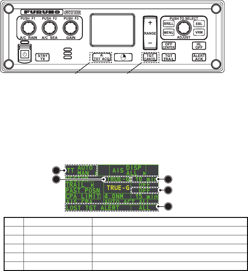
3.2 TT Controls
The control unit has two keys which you can use during target tracking mode. The
keys are indicated in the figure below.
• TGT ACQ: Acquires the selected echo as a target.
• TGT CANCEL: Deactivates tracking for the cursor-selected target.
These functions, along with other TT functions, can also be accessed from the
[CURSOR] menu (See section 1.7).
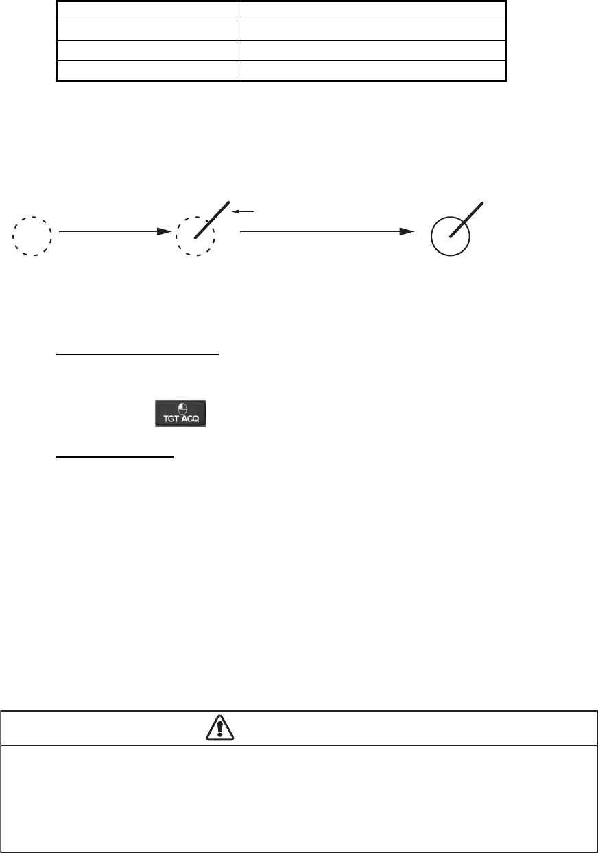
3.3 TT Box Overview
3.4 How to Select the TT mode
Target tracking is available in three modes: [MANUAL 50] (up to 50 targets, selected
manually), [MANUAL 25•AUTO 25] (up to 50 targets, 25 selected automatically, 25
selected manually) and [AUTO 50] (up to 50 targets, selected automatically). To select
a target tracking mode, do the following:
1. Select the [TT] box, then press the right button. The [TT TARGET MENU] is
displayed.
2. Select [TT SELECT], then press the ADJUST knob.
3. Select the appropriate mode, then press the ADJUST knob.
4. Close the menu.
No. Indication name Description/remarks
1 TT acquisition mode Shows current TT mode (AUTO, AUTO/MAN, MAN)
2 Vector time Adjusts the vector time for the selected target
3 Vector reference True, Relative referencing for this target’s vector
4 Past position time Sets the interval for the target’s trail
5 Lost TGT Alert Display/hide the alert when a target is lost
Manual target acquisition Cancel target
1
5
4
32
3. TARGET TRACKING (TT)
3-3
3.5 How to Activate/Deactivate Target Tracking
Place the cursor on the TT acquisition mode indicator, then press the left button. The
indication changes, depending on the TT mode selected (See section 3.4). The table
below shows the indication changes based on mode selection.
The plotting symbol is drawn by broken lines during the initial acquisition stage. A
vector appears in about one minute after acquisition indicating the target's motion
trend. If the target is consistently detected for three minutes, the plotting symbol
changes to a solid circle. If acquisition fails, the target plotting symbol blinks and
disappears shortly.
3.5.1 How to manually acquire targets
Manual target acquisition can be done with one of two methods:
Using the control unit
1. Place the cursor on the target to be acquired.
2. Press the key.
Using the menu
1. Select the operational display area, then press the right button. The [CURSOR]
menu is display.
2. Select [TARGET DATA/ACQ], then press the ADJUST knob.
3. Place the cursor on the target to be acquired, then press the ADJUST knob.
Note 1: For successful acquisition, the target to be acquired should be within 0.1 to
24 nm (or 32 nm, depending on initial setting) from own ship and not obscured by sea
or rain clutter.
Note 2: When the capacity for manual acquisition is reached, the message "TT TAR-
GET FULL(MAN)" is displayed at the screen bottom. Cancel tracking of
non-threatening targets if you wish to acquire additional targets manually.
TT mode selected Indication change
[Manual 50] "OFF" "MAN" "OFF"...
[MANUAL 25•AUTO 25] "OFF" "MAN/AUTO" "OFF"...
[AUTO 50] "OFF" "AUTO" "OFF"...
At acquisition Within 1 min. after acquisition Within 3 min. after
acquisition
Vector
CAUTIONCAUTION
Target Swap
When a target being tracked nears another target being tracked, the targets may be "swapped".
When two targets acquired either automatically or manually come close to each other, one of
the two may become a Lost Target. Should this happen, manual re-acquisition of the Lost
Target may be required after the two have separated.
3. TARGET TRACKING (TT)
3-4
3.6 How to Enter Own Ship Speed
The TT requires own ship's speed and heading data. The speed can be STW, SOG
or echo-referenced speed (based on 3 max. stationary objects). Manual input is also
possible.
For automatic or manual input, see section 1.12. For echo-referenced speed input
follow the procedure below.
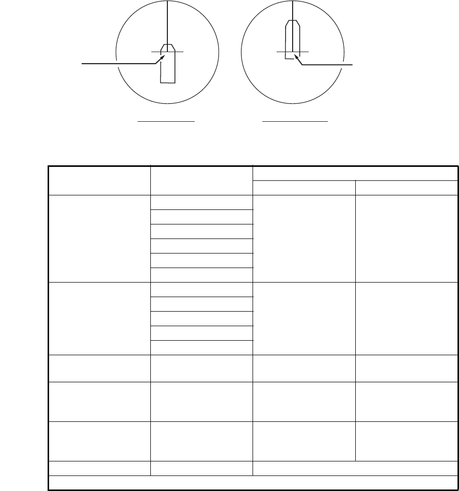
3.6.1 Echo-referenced speed input
The use of echo-referenced speed is recommended when:
• The speed log is not operating properly or not connected to the radar.
• The vessel has no device (doppler sonar, speed log, etc.) that can measure ship's
bow-stern, port-starboard movement.
If you select echo-referenced speed, the TT calculates own ship's speed relative to a
fixed reference target. The number of targets may be R1, R2 or R3. When a plural of
objects are selected, the mean value is used, for stabilization and speed.
1. Select the operational display area, then press the right button. The [CURSOR]
menu is displayed.
2. Select [REF MARK], then press the ADJUST knob. The cursor is highlighted.
3. Place the cursor on the location to be used as a reference, then press the
ADJUST knob. The cursor changes from the highlighted cross to a circle with
dashed lines, indicating that the reference location is now set. See section 3.8 for
more information on TT symbols and their attributes.
The dashed lines of the reference point change to a solid line over time, as shown
in the figure above.

3. TARGET TRACKING (TT)
3-5
Notes on speed input by reference target
• Reference targets are only used for the calculation of true speed.
• Do not use reference target generated true speed to calculate relative speed.
Relative speed data is not accurate because response to speed change is slow,
hampering the TT's ability to accurately judge the possibility of collision.
• Select a stationary target as a reference target to calculate own ship speed as
ground tracking speed. Do not choose a moving target as a reference target. A
moving target produces error in the vector for TT and AIS, which results in wrong
collision avoidance information. Further, an unstable stationary target produces
inaccurate speed data and the target itself may become lost.
• When a reference target is lost or goes out of the acquisition range, that reference
target mark blinks and the indication "REF TARGET LOST" appears in the alert box.
If all reference targets are lost, the speed indication reads "*.*" Select a different
reference target if currently selected one is lost.
• When all targets are deleted, the reference target mark is also deleted and the
target-based speed becomes invalid. The speed is indicated as "BTREF" where BT
means Bottom Track (speed over ground).
• Reference targets can be marked with a vector.
This can be done with [REF TARGET VECTOR] on the [TT TARGET] menu.
• Loss of reference target will affect the calculation of true speed and true course of
targets. Further, own ship speed will be inaccurate.
How to cancel echo-referenced speed input
1. Open the [MAIN MENU].
2. Select [SHIP SPEED MENU], then press the ADJUST knob.
3. Select [SHIP SPEED], then press the ADJUST knob.
4. Select any option, other than [REF] or [MANUAL], then press the ADJUST knob.
5. Close the menu.
3. TARGET TRACKING (TT)
3-6
3.7 Lost Target
Targets not detected in five consecutive scans become “lost targets”. A lost target is
shown in the display with flashing red "X". Flashing stops after lost target alert is
acknowledged.
If you are in an area where tracked targets are lost frequently you may want to disable
the lost target alert against tracked targets by maximum range or minimum speed.
3.7.1 How to set the lost target filter
You can set the lost target alert to sound against lost targets that are within a specific
range. To set the criteria, use the procedure below.
1. Open the [MAIN MENU].
2. Select [TT•AIS], then press the ADJUST knob.
3. Select [TT LOST FILTER], then press the ADJUST knob.
4. Select [MAX RANGE], then press the ADJUST knob.
5. Select [ON], then press the ADJUST knob. The settings can now be adjusted.
6. Rotate the ADJUST knob to adjust the setting as required, then press the
ADJUST knob to apply the setting.
7. Close the menu.
Note: Reference targets are not affected by this filter.
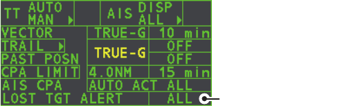
3.7.2 How to enable/disable the lost target alert
The [LOST TARGET ALERT] box at the bottom right corner enables and disables the
lost target alert. Select the box with the cursor, then press the left button to select
[OFF], [ALL] or [FILT] as appropriate.
• [OFF]: Disable the alert.
• [ALL]: Enable the alert for all lost targets, including filtered targets.
• [FILT]: Enable the alert for all lost targets, excluding filtered targets.
Lost target alert box
3. TARGET TRACKING (TT)
3-7
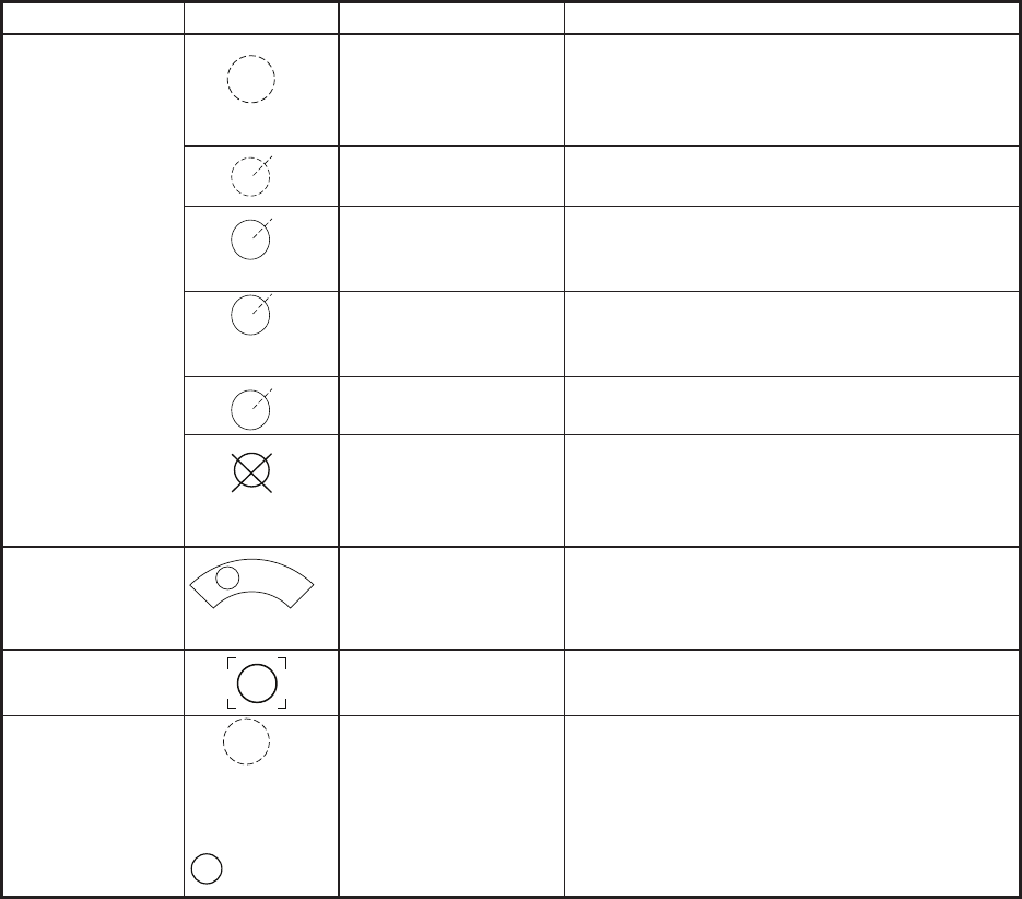
3.8 TT Symbols and Attributes
3.8.1 TT symbols
3.8.2 How to adjust symbol brilliance
1. Place the cursor on the [BRILL] box, then press the right button. The [BRILL]
menu is displayed.
2. Select [TT SYMBOL], then press the ADJUST knob. The settings can now be
adjusted.
3. Rotate the ADJUST knob to select the desired brilliance, then press the
ADJUST knob to apply the setting.
4. Close the menu.
skrameRsutatSlobmySmetI
Initial stage Broken circle around an echo to indicate
the target under acquisition and initial
stage of tracking, before steady-state
tracking.
Within one minute after acquisition (vector
still unreliable).
Steady tracking Solid circle with vector indicating steady
state tracking (within three minutes after
acquisition).
(flashing)
CPA alarm Plotting symbol (red) flashes to indicate
the target is predicted to come into CPA or
TCPA.
CPA alarm
acknowledge
Shown in red, and flashing stops after
CPA/TCPA alarm is acknowledged.
Automatically
acquired targets
(flashing)
Lost target A red X is crossed through the TT symbol
to indicate that it is a lost target. Flashing
stops after lost target alert is
acknowledged.
Manually
acquired targets
(the width of the
line for "steady
tracking" TT is
thicker than that
of the auto-
matically
acquired target)
Acquisition zone
(flashing)
On target passing
through operator-set
acquisition zone
Symbol is red and flashing.
Target selected
for data readout
On selected target Target data (range, bearing, course,
speed, CPA, TCPA, BCR, BCT, etc.).
Reference target
R
After three
minutes,
changes to
R
On reference target Used to calculate own ship’s
over-the-ground speed (echo-referenced
speed) for ground stabilization.
3. TARGET TRACKING (TT)
3-8
3.8.3 How to set the symbol color
1. Open the [MAIN MENU].
2. Select [TT•AIS], then press the ADJUST knob.
3. Select [TT•AIS SYMBOL], then press the ADJUST knob.
4. Select [SYMBOL COLOR], then press the ADJUST knob. The settings can now
be adjusted.
5. Select the appropriate color, then press the ADJUST knob.
6. Close the menu.
3.9 How to Display/Remove Target Data
The TT mode provides the full functionality of TT as required by the IMO Resolution
A.823(19) and IEC 62288, including display of range, bearing, course, speed, CPA
and TCPA of all tracked targets.
The target bearing is shown in relative bearing in the HEAD UP mode and true bearing
in the COURSE UP, NORTH UP and True Motion modes, with the suffix "R" (Relative)
or "T" (True).
The target speed and course are shown as speed over the ground or speed through
the water depending on speed source.
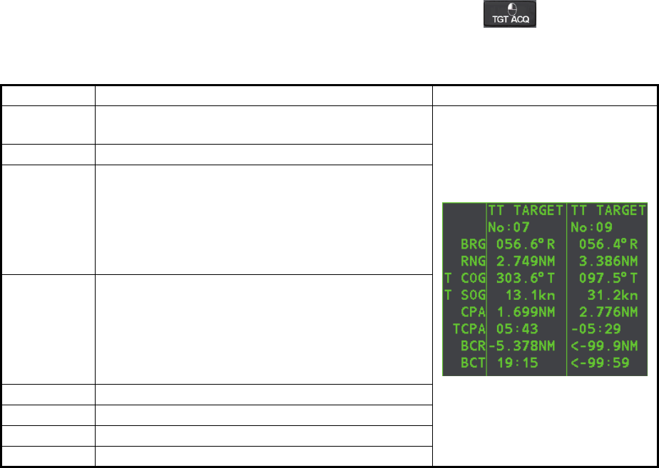
3.9.1 How to display target data
Place the cursor on a desired tracked target and press the key. The target’s
shape changes to a square and the selected TT target’s data is shown in the data
display area.
You can display the target data for two targets in one data box and the data for as
many as six targets can be displayed.
Indication Description
BRG Bearing from own ship to target in relative (R) or
True (T) reference.
RNG Range from own ship to target.
T COG Relative (R) or True (T) Course Over Ground of
target.
Displayed as "T CTW" where speed input is set to
[LOG(WT)].
Displayed as "R CRS" where speed data is not
available.
T SOG Relative (R) or True (T) Speed Over Ground of
target.
Displayed as T STW where speed input is set to
[LOG(WT)].
Displayed as R SPD where speed data is not
available.
CPA Closest Point of Approach of target to own ship.
TCPA Time to CPA of target to own ship.
BCR Bow crossing range of target.
BCT Bow crossing time of target.
3. TARGET TRACKING (TT)
3-9
3.9.2 How to remove target data
Place the cursor on a desired tracked target and press the key. The select
target’s data is no longer displayed in the data display area.
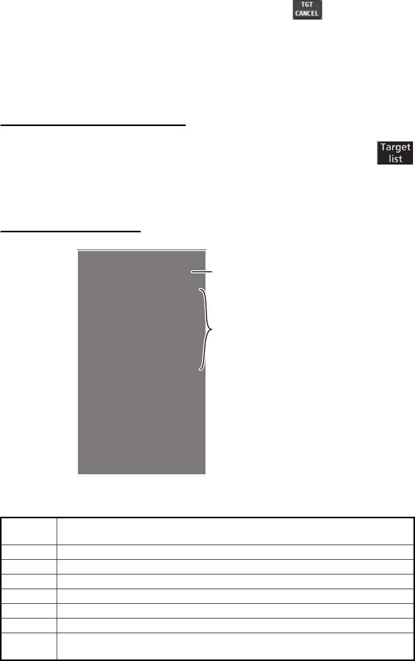
3.9.3 How to display, hide and sort the target list
The target list provides a comprehensive data display of all TT (and AIS) targets being
tracked.
How to display/hide the target list
1. Select the [Target List] menu item at the bottom-right of the screen, then
press the left button. The target list is displayed inside the information
box.
2. Select the [Target List] menu item at the bottom-right of the screen, then press the
left button to hide the target list.
How to sort the target list
1. With the target list displayed, select [Sort by], then press the ADJUST knob.
2. Select the sort method, referring to the table below, then press the ADJUST knob.
3. Select the appropriate filter option, if required, then press the ADJUST knob.
Note: Targets with no data are sorted to the back of the list, regardless of filter setting.
Sort
method Description
[CPA] Targets are sorted in order from closest to farthest CPA.
[TCPA] Targets are sorted in order from shortest to longest TCPA.
[BCR] Targets are sorted in order from closest to farthest BCR.
[BCT] Targets are sorted in order from shortest to longest BCT.
[RANGE] Targets are sorted in order from closest to farthest range.
[SPEED] Targets are sorted in order from fastest to slowest.
[NAME] Targets are sorted in Alphabetical order. Unknown names are displayed
last.
[TARGET LIST (1/2)]
SORT BY CPA
1 BACK(L=TOP)
2 AIS TARGET NAME
NAME FURUNOMARU
BRG 232.8°R RNG 2.19NM
CPA 0.13NM TCPA -05:34
3 TT TARGET
NO.4
BRG 049.6°R RNG 0.75NM
CPA 0.16NM TCPA> 99:59
9 REFRESH DATA
0 NEXT (L=LAST)
Target details
Sorting method

3. TARGET TRACKING (TT)
3-10
3.10 Vector Modes
Target vectors can be displayed relative to own ship’s heading (Relative) or North
(True).
Note: IMO recommends the use of true vector mode in sea stabilization or relative
vector mode for collision avoidance.
To change the vector mode, do the following:
Place the cursor on the vector reference indication in the [Vector] box, then press the
left button. The vector reference cycles through the following settings with each press
of the left button.
[REL] [TRUE-G/TRUE-S] [REL]...
3.10.1 Description of vectors
Stabilization modes
It is important to select the optimum stabilization mode for the radar display. To assess
risk of collision the relative motion of a target gives the clearest indication of CPA and
may be monitored by observing either the direction of the target's relative trail, or the
CPA predicted by the relative vector. By default, relative motion displays relative target
trails and true motion displays true target trails. Where true target trails is selected, a
sea stabilized display will indicate all targets' motion through the water. A ground sta-
bilized display will indicate all targets' motion over the ground.
In coastal, estuarial and river waters where a significant set and drift may be experi-
enced, a sea stabilized display will produce significant target trails from all fixed (sta-
tionary) objects possibly producing an unacceptably high level of clutter and masking.
In such circumstances a ground stabilized display may reduce its effect and enable
the observer to detect clearly the trails of moving targets, thus enhancing the observ-
er's situational awareness.
However, the display should be considered only as an approximation of the course
and speed made good over the ground. Among other factors, the accuracy of the
ground-stabilization is affected by inaccuracies in speed and heading inputs as well
as radar measurement imprecision and will require the display to be readjusted peri-
odically. The information displayed should be interpreted with due regard to these fac-
tors.
Note: It should be noted that in determining a target's aspect by radar; the calculation
of its true track is dependent on the choice and accuracy of the own ship's course and
speed input. A ground-stabilized target plot may accurately calculate the ground track
of the target, but the target's heading may be significantly different from its track when
experiencing set, drift or leeway. Similarly, a sea stabilized target plot may be inaccu-
rate when own ship and the target, are experiencing different rates of set, drift or lee-
way.
3. TARGET TRACKING (TT)
3-11
Ground stabilization and sea stabilization
Target vectors can be ground stabilized or sea stabilized in the True Motion mode. To
select speed over the ground or speed through the water data, open the page from the
menu. Select for ground stabilization or for sea stabilization. The Vector mode indica-
tion shows the stabilization mode in the true motion as [TRUE-G] or [TRUE-S].
Sea stabilization is a mode where own ship and all targets are referenced to the sea
using a compass heading and single-axis log water speed inputs in the true motion
mode. Ground stabilization is a mode where own ship and all targets are referenced
to the ground using the ground track or set and drift inputs. If the accuracy seems un-
satisfactory, enter set and drift corrections. Note that set and drift should not be used
when the radar is displaying AIS targets.
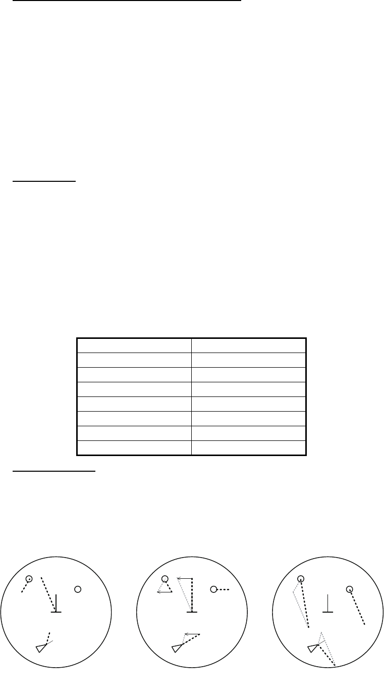
True vector
In the true motion mode, all fixed targets such as land, navigational marks and ships
at anchor remain stationary on the radar screen with vector length zero. But in the
presence of wind and/or current, the vectors appear on fixed targets representing the
reciprocal of set and drift affecting own ship unless set and drift values are properly
entered.
In the true vector mode, there are two types of stabilization: ground stabilization
(TRUE-G) and sea stabilization (TRUE-S). The stabilization mode is automatically se-
lected according to speed selection, as shown in the table below. Manual selection is
available from the [SPD] menu at the top-right of the screen.
Relative vector
Relative vectors on targets that are not moving over the ground such as land, naviga-
tional marks and ships at anchor will represent the reciprocal of own ship's ground
track. A target whose vector passes through own ship is on a collision course. (Dotted
lines in the figure are for explanation only.)
Speed selection True vector mode
LOG(WT) TRUE-S
LOG(WTC) TRUE-G
LOG(BT) TRUE-G
GPS(BT) TRUE-G
REF(BT) TRUE-G
MAN(WT) TRUE-S
MAN(WTC) TRUE-G
Buoy
Own Ship
True vectors in ground
stabilization
AIS
Buoy
Own Ship
True vectors in sea
stabilization
TT
AIS
TT
Buoy
Own Ship
Relative vectors
AIS
TT
Current
(Set and drift)