Furuno USA 9ZWRTR101 Transceiver for Radar model FAR-1518/1528 User Manual
Furuno USA Inc Transceiver for Radar model FAR-1518/1528
Contents
- 1. Installation Manual Part 3
- 2. Installation Manual Part 1
- 3. Installation Manual Part 2
- 4. Installation Manual Part 4
- 5. Installation Manual Part 5
- 6. Installation Manual Part 6
- 7. User Manual Part 1
- 8. User Manual Part 2
- 9. User Manual Part 3
- 10. User Manual Part 4
- 11. User Manual Part 5
- 12. User Manual Part 6
Installation Manual Part 2
2. WIRING
2-5
10. Connect the coaxial cable to the TNC connector (local supply).
11. Set the transceiver module to the antenna unit. Connect plugs P821, P801, P802,
P822 and the TNC connector. Push the transceiver module in until it stops, and
then tighten fixing bolts. Be sure to push in the transceiver unit until it stops.
Failure to do so may cause microwave leakage.
12. Fasten the shield wire to the wing nut on the transceiver module.
13. Confirm that all screws are tightened and all wirings are properly made. Confirm
that waterproofing gasket, bolts and tapping holes of antenna unit are coated with
silicone grease. Close the antenna unit cover.
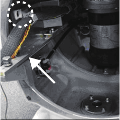
Pass the coaxial cable behind the plate
(pointed by arrow) and the clamp
(circumscribed with a dashed circle).
2. WIRING
2-6
2.3 How to Connect the Signal Cable for FAR-1513,
FAR-1523
In order to minimize the chance of picking up electrical interference, avoid where pos-
sible routing the signal cable near other onboard electrical equipment. Also, avoid run-
ning the cable in parallel with power cables.
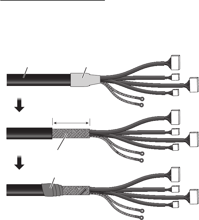
How to fabricate the signal cable
Fabricate the signal cable as follows:
1. Remove shrink tubing from the signal cable.
2. Remove vinyl sheath approx. 50 mm.
3. Wrap vinyl tape at the end of the vinyl sheath.
Cut sheath approx. 50 mm.
Sheath
50
50
Remove shrink tubing.
Braided shield
Vinyl tape
2. WIRING
2-7
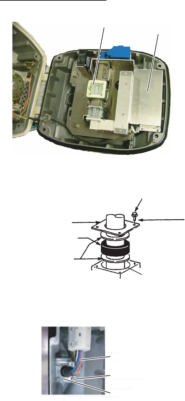
How to connect the signal cable
1. Open the antenna cover by loosening four bolts, and then fix the stay.
2. Unfasten the cable gland assembly (gasket, flat washer).
3. Pass the signal cable with connector through the bottom of the antenna unit chas-
sis. Pass the cable through the gland assembly as shown below.
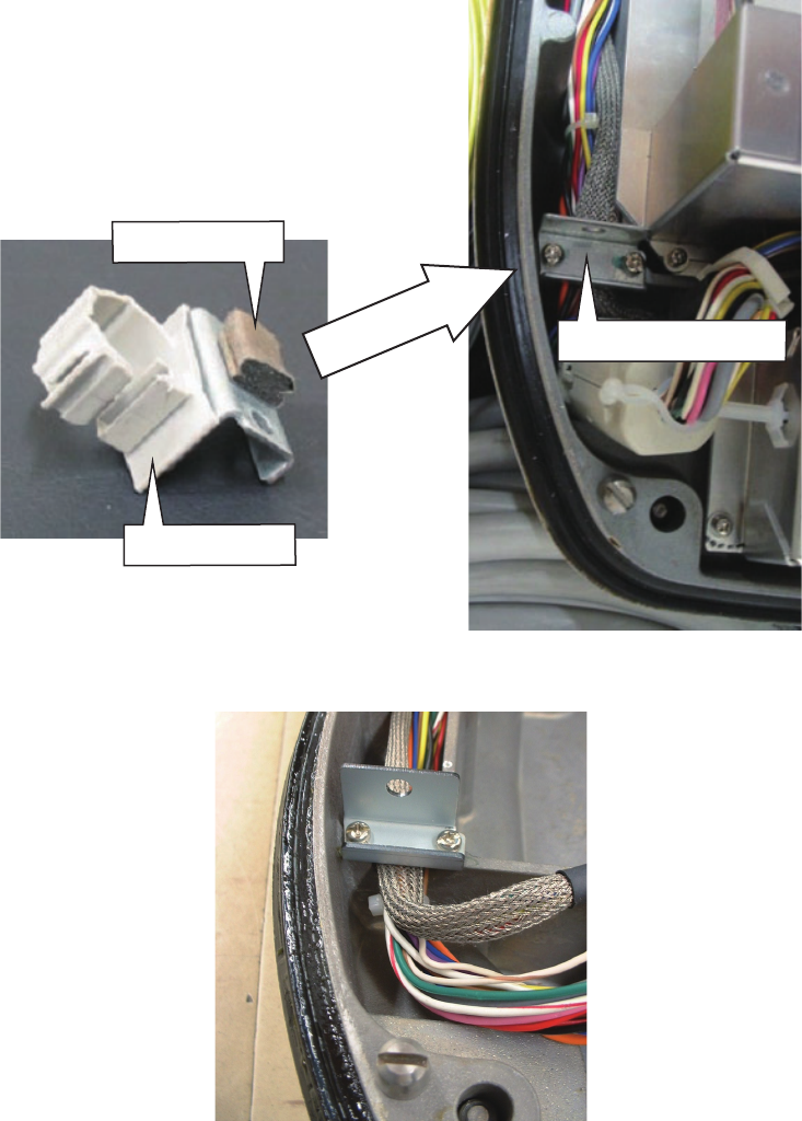
4. Fasten the gasket support with four bolts. Using one of the four bolts, fasten the
crimp-on lug to the shield wire.
5. Fasten the crimp-on lug on the shield to one of the fixing bolts of the cable gland
assembly.
6. Unfasten four screws to remove the RTB board cover.
Cable entry
RTB board cover
Cable entry
Gasket support
Gasket
Flat washer
4-M4x16
Fixing bolt
Cable entrance
Signal cable
Gasket
Fasten shield to screw.
2. WIRING
2-8
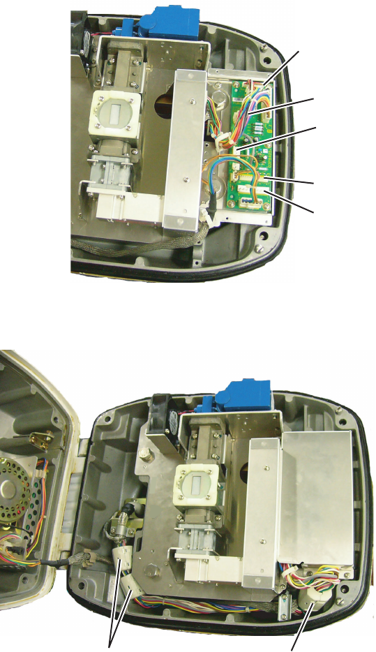
7. Connect the plugs of the signal cable to the RTB board.
8. Reattach the RTB board cover.
9. Attach three EMI cores to the signal cable at the locations shown below.
RTB board
J820
J823
J824
J821
EMI Core RFC-13 (2 pcs) EMI Core RFC-H13 (1 pc)
2. WIRING
2-9
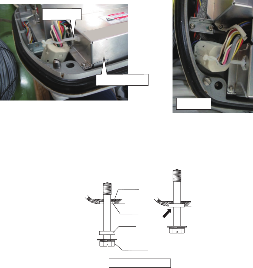
10. Fasten the signal cable with the cable clamp as follows.
a) Dismount the cable clamping plate and remove the cable clamp and gasket.
b) Run the signal cable as shown below.
Cable clamping plate
Remove clamp.
Remove gasket.
2. WIRING
2-10
c) Fasten the signal cable with the cable clamp as shown below.
11. Release the stay and close the cover. Loosely fasten the fixing bolts; you will have
to make some adjustments inside after completion of wiring.
Note: When closing the cover, set the gaskets to the grooves in the bottom chassis,
then tighten the fixing bolts.
Top view
RTB board cover
Cable clamp
Bottom
chassis
Gasket
Groove
Fixing bolt
Torque : 9.8 ±0.1 Nm