Furuno USA 9ZWRTR102 Transceiver for Radar User Manual OME 36700 A
Furuno USA Inc Transceiver for Radar OME 36700 A
UserManual.wiki
>
Furuno USA
>
9ZWRTR102 User Manual
>
Users Manual 4
Contents
1.
Users Manual 1
2.
Users Manual 2
3.
Users Manual 3
4.
Users Manual 4
5.
Users Manual 5
Users Manual 4
Navigation menu
Upload a User Manual
Namespaces
Wiki Guide
HTML
PDF
Info
Views
User Manual
Discussion / Help
Navigation
![1. OPERATION1-531.33.2 How to show wind data or date alternatelyClick the icon shown below to show wind data or date alternately.Wind direction formatWind direction format can be selected on the [NAV DATA] menu, with the [WIND] window.1. Open [MAIN MENU], click [NAV DATA].2. Click [WIND].3. Click [WIND].4. Click [WIND DIRECTION] then click [GO TO] or [COME FROM], referring to the figure right. [OFF] hides the wind direction.Date menuThe [DATA] menu lets you select the time to display, [UTC] or [LOCAL]. Right-click the Date icon to show the [DATE] window.• [DATE-TIME]: Select how to display format of date and time, [UTC] or [LOCAL].Note: If [LOCAL] is selected, the indication [LOCAL] is not shown.• [LOCAL TIME ADJ]: If [LOCAL] is selected at [DATE-TIME], set the time difference between local time and UTC time.Wind speed Date(at the top right corner on the screen)ClickCAPT±300°/min±180°SPD BT GPS-F►DPT AFT ►CURSOR TTG 18m20s44. 6km/h3. 2mCAPT±300°/min±180°OS POSN NCURSOR TTG 18m20s2. 4m/s0° 00. 219° E0° 00. 397° ►WINDWIND6.34NM / 300.3°R01-sep-2012 ►01-sep-2012 ►6.34NM / 300.3°RUTC 12:341 BACK2 [PREDICTION]3 [DEPTH]4 [WIND] [WIND] [WIND]1 BACK2 WIND DIRECTION OFF/COME FROM/GO TOWind direction symbol: [GO TO]Wind direction symbol: [COME FROM]Date icon (at top right corner on the screen)Right-clickUTC 12:34CAPT±300°/min±180°SPD BT GPS-F►DPT AFT ►CURSOR TTG 18m20s6.34NM / 300.3°R44. 6km/h3. 2m01-sep-2012 ►01-sep-2012 ► [DATE]1 BACK2 DATE-TIME UTC/LOCAL3 LOCAL TIME ADJ +00:00](https://usermanual.wiki/Furuno-USA/9ZWRTR102.Users-Manual-4/User-Guide-3763531-Page-1.png)
![1. OPERATION1-541.33.3 Time to the cursor positionThe time from own ship to the cursor position (TTG: time-to-go) is shown at the top right corner on the screen.1.33.4 Cursor positionThe cursor position (range and bearing of cursor from the own ship) is shown at the top right corner on the screen.The bearing reference is changed simultaneously with the EBL1 reference. To change the cursor position's bearing reference, click EBL1's bearing reference icon. See section 1.19 for details. 1.33.5 ROT, Rudder and Autopilots GraphsThe ROT (Rate of Turn), RUDDER and AUTOPILOT graphs appear at the top of the screen.ROT graphThe ROT graph displays ship’s rate of turn (degrees/min), using the ROT signal fed from an ROT sensor. There is no NMEA signal and also no indication.To set the ROT graph scale:1. Open [MAIN MENU] then click [NAV DATA].2. Click [ROT SCALE].3. Click the desired scale among 30 degees, 90 degrees and 300 degrees.Rudder graphThe rudder graph shows the rudder angle. There is no NMEA signal and also no indication.To set the rudder graph scale:1. Open [MAIN MENU] then click [NAV DATA].2. Click [RUDDER SCALE].3. Click the desired scale among 30 degrees, 90 degrees, 120 degrees and 180 degrees.CAPT±300º/min±180ºOS POSN NCURSOR TTG 18m20s24m/s0° 00. 219°WIND E0° 00. 397° ►6.34NM / 300.3°RCAPT±300º/min±180ºOS POSN NCURSOR TTG 18m20s2. 4m/s0° 00. 219°WIND E0° 00. 397° ►6.34NM / 300.3°RROTRUDDER±300 º/min±180 ºRUDDER graphAutopilot graphROT graph](https://usermanual.wiki/Furuno-USA/9ZWRTR102.Users-Manual-4/User-Guide-3763531-Page-2.png)
![1. OPERATION1-55Autopilot graph1) Follow-up (FU) modeWhen the autopilot is in the follow-up mode, the follow-up rudder command is indicated on the RUDDER scale. In addition, "FOLLOW UP" is indicated at the top of the screen. In follow-up mode, the autopilot controls the rudder so that actual rudder angle becomes same as commanded one.2) Autopilot (AP) modeWhen the autopilot is in the "autopilot" mode and a ROT signal is available from the autopilot, the autopilot graph shows ROT command. The actual ROT command set on the autopilot is represented by a small circle on the ROT scale. In addition, " AUTOPILOT" is indicated at the top of the screen. In "autopilot" mode, the autopilot controls the ROT so that actual heading becomes same as commanded one.3) Neither FU nor AP modeWhen the autopilot is in neither FU nor AP mode, the autopilot graph shows ROT command as default.4) No autopilot or on standbyThere is no NMEA signal and also no indication.1.34 Customized MenusThe customized menu settings of four users are programmed individually. A user can have the four sets of the menu settings. That is, there are 16 sets of the menu settings.How to select the customized set1. Click the [CUSTOM] icon at the bottom right corner on the screen to show the [CUSTOM MENU] window.2. Click the required user name.3. Click the required menu set.4. Click outside the menu window to close the menu.Customized menu settings 4 setsUSER 1USER 2USER 3USER 416 setsClickFTC 1IR 1ES 2EAV 3TRAIL►2.50sec00m03sRELONCUSTOM3-4►CUSTOM3-4►1 BACK2 USER NAME 1 CUSTOM1-1/ CUSTOM1-2/ CUSTOM1-3/ CUSTOM1-43 USER NAME 2 CUSTOM2-1/ CUSTOM2-2/ CUSTOM2-3/ CUSTOM2-44 USER NAME 3 CUSTOM3-1/ CUSTOM3-2/ CUSTOM3-3/ CUSTOM3-45 USER NAME 4 CUSTOM4-1/ CUSTOM4-2/ CUSTOM4-3/ CUSTOM4-4 [CUSTOM MENU]](https://usermanual.wiki/Furuno-USA/9ZWRTR102.Users-Manual-4/User-Guide-3763531-Page-3.png)
![1. OPERATION1-56How to edit the [CUSTOM MENU]Note: The [CUSTOM1-1] setting is fixed as a default setting. You can edit the setting, but when the system is turned off, the default setting is restored. To save a customized set, select a setting other than [CUSTOM1-1].1. Right-click the [CUSTOM] icon at the bottom right corner on the screen to show the [CUSTOM MENU] window.2. Click [EDIT].3. Click [USER NAME] to edit.4. To edit the name, click the name column then enter the name with the software keyboard. Click the [END] button to finish.• Change the digit: Rotate scrollwheel.• Delete a character: Use the [BS] button on the software keyboard.5. Click [USER COMMENT] to edit. The editing procedure is the same as that for [USER NAME]. Refer to step 4 6. To edit the name, press the name column then enter the name with the software keyboard. Click the [END] button to finish.Right-clickFTC 1IR 1ES 2EAV 3TRAIL►2.50sec00m03sRELONCUSTOM3-4►CUSTOM3-4► [CUSTOM MENU]1 BACK2 [EDIT]3 [PRESET] [EDIT]1 BACK2 USER NAME USER NAME 13 USER COMMENT CUSTOM4-44 [GAIN/STC/RAIN]5 FTC OFF/1/26 INT REJECT OFF/1/2/37 ECHO STRETCH OFF/1/2/38 ECHO AVERAGE OFF/1/2/39 WIPER OFF/ON10 VIDEO CONTRAST TYPE A/B/C/D11 [STC CURVE]12 LOW LEVEL ECHO 013 TT ECHO LEVEL 1314 [PULSE WIDTH (RIVER)]16 SAVE & QUIT #15 [PULSE WIDTH (SEA)] for [SEA] mode instead of #14[EDIT]1 BACK2 USER NAMEUSER NAME 13 USER COMMENTCUSTOM4-44 [GAIN/STC/RAIN]Name column[END] button[EDIT]1 BACK2 USER NAMEUSER NAME 13 USER COMMENTCUSTOM4-44 [GAIN/STC/RAIN]Name column](https://usermanual.wiki/Furuno-USA/9ZWRTR102.Users-Manual-4/User-Guide-3763531-Page-4.png)
![1. OPERATION1-577. Click the menu to set in the [EDIT] menu.8. Click the setting for each menu.9. Click [SAVE & QUIT] to save the setting.1.35 SD CardsThe SD card (including SDHC card) stores the mark data etc.1.35.1 About the SD cards• Use SD cards carefully. Wrong use can damage the card and destroy its contents.• Make sure the cover of the card drive is closed at all times.• Remove a card with only your fingers. Do not use metal tools (like tweezers) to remove the card.• Do not remove a card during the reading of the card or writing to the card.• If there is water at the bottom of the card cover, DO NOT open the cover. Remove the water with a dry cloth completely and then open the cover.• The SD cards with the SD or SDHC logo can be used (max. 32 GB). Some SD cards may not work correctly depending on the card type or maker. The memory cards in the table below have been tested and confirmed:How to format an SD cardYou need to format an SD card for use with your PC. If the card becomes corrupted, format the card with a formatting program that is compatible with the specifications of the SD card. The SD Memory Card Formatting Software made by Panasonic is an example.Type Capacity Maker ClassSDSDB-8192-J95A 8 GB SanDisk 4SDSDX-008G-J95 8 GB SanDisk 10SD-E008G4 8 GB TOSHIBA 4RP-SDW08GJ1K 8 GB Panasonic 10SDSDX-016G-J35 16 GB SanDisk 10RP-SDWA16GJK 16 GB Panasonic 10 [EDIT]1 BACK2 USER NAME USER NAME 13 USER COMMENT CUSTOM4-44 [GAIN/STC/RAIN]5 FTC OFF/1/26 INT REJECT OFF/1/2/37 ECHO STRETCH OFF/1/2/38 ECHO AVERAGE OFF/1/2/39 WIPER OFF/ON10 VIDEO CONTRAST TYPE A/B/C/D11 [STC CURVE]12 LOW LEVEL ECHO 013 TT ECHO LEVEL 1314 [PULSE WIDTH (RIVER)]16 SAVE & QUIT #15 [PULSE WIDTH (SEA)] for [SEA] mode instead of #14Menus to set](https://usermanual.wiki/Furuno-USA/9ZWRTR102.Users-Manual-4/User-Guide-3763531-Page-5.png)
![1. OPERATION1-58How to set an SD cardThe processor unit has two slots for SD cards. The [SD-1] is upper slot and [SD-2] is lower.1. Pull the tab on the card drive on the processor unit to open the card drive.2. Put the SD card in the either card drive, [SD-1] or [SD-2], with the label upward. If the card does not set easily, do not use force.3. Push the card until the card is in position.How to remove an SD cardTo remove an SD card, select [SD-1] or [SD-2] from the [REMOVE EXTERNAL MEDIA] menu. There are two methods to open [REMOVE EXTERNAL MEDIA] as follows.• [MAIN MENU]–[FILES]–[REMOVE EXTERNAL MEDIA]• [MAIN MENU]–[CAPTURE]–[REMOVE EXTERNAL MEDIA]1. On [FILES] or [CAPTURE] menu, select [REMOVE EXTERNAL MEDIA].2. Select the SD card to remove, [SD-1] or [SD-2].Note: Select the same card as the card selected on the [DRIVE SELECT] menu.3. Pull the tab on the card drive cover to open the card drive.4. Push the card to release the card from the card drive.5. Remove the card with your fingers then close the cover.Note: Always remove an SD card by this method to prevent non-recognition of the card the next time when it is inserted. If a card is not recognized, insert the card again and do the above operation.1.35.2 How to save and replay the dataAll SD card operations begin from the [FILES] menu. The [FILES] menu is available in stand-by mode.The data witch is saved in the FR-1908V-BB do not have the compatibility with other models. Do not let the data read to the other models, and also do not let other models read the data of the FR-1908V-BB. It may cause the malfunction. Note: All settings, except for [BRILL 1-1] and [CUSTOM 1-1], are stored when the radar is turned off. If you want to keep all settings, including [BRILL 1-1] and [CUSTOM 1-1], save the settings to an SD card before turning off the radar. Then replay the saved settings after turning on the radar.• [DRIVE SELECT]: Click the drive [SD-1] or [SD-2] to use. The [SD-1] is upper slot and [SD-2] is lower.• [DRIVE INFO]: Confirm the remaining capacity of the SD card selected at [DRIVE SELECT]. [FILES]1 BACK2 DRIVE SELECT SD-1 /SD-23 [DRIVE INFO]4 [SAVE DATA]5 [REPLY (READ) DATA]6 [DELETE DATA]7 REMOTE EXTERNAL MEDIA SD-1 /SD-2](https://usermanual.wiki/Furuno-USA/9ZWRTR102.Users-Manual-4/User-Guide-3763531-Page-6.png)
![1. OPERATION1-59• [SAVE DATA]: Save the file stored on the following file group set at [NAME]. Set the name with the software keyboard. Click the [END] key to complete the name setting. [MARK/LINE]* (see the figure shown right) [SETTING DATA] [ALARM HISTORY] [LOG FILE]• [REPLAY (READ) DATA]: Select the data group in the SD card, [MARK/LINE]* or [SETTING DATA], then select the file to replay (read).• [DELETE DATA]: Select the data group to delete from SD card, [MARK/LINE]*, [SETTING DATA], [ALARM HISTORY] or [LOG FILE], then select the file to delete.• [REMOVE EXTERNAL MEDIA]: Select the SD card ([SD-1] or [SD-2]) to remove from the card slot safely.Note: Select the same card as the card selected on the [DRIVE SELECT] menu.*: [RIVER] mode only1.36 How to Set Menu and Icon Behavior1.36.1 Auto closing of menu windowIn the [SEA] mode, the menu window can be set to close automatically if there is no menu operation within the specified period.You can close the menu window automatically after a certain period with no operation.Note: This function is for the [SEA] mode only. 1. Open [MAIN MENU], click [DISPLAY].2. Click [MENU].3. Click [AUTO-CLOSING].Note: In the [RIVER] mode, auto closing is fixed to [ON]. Go to step 5 to select the closing time.4. Click the [ON] or [OFF] as applicable.5. Click [AUTO-CLOSING TIME].6. Click the appropriate time to close the menu window automatically among 5 sec, 10 sec and 20 sec.7. Click outside the menu window to close the menu. [MARK/LINE]1 BACK2 NAME M0000000[END] key [MENU]1 BACK2 AUTO-CLOSING OFF/ON3 AUTO-CLOSING TIME 5sec/10sec/20sec](https://usermanual.wiki/Furuno-USA/9ZWRTR102.Users-Manual-4/User-Guide-3763531-Page-7.png)
![1. OPERATION1-601.36.2 IconsYou can show or hide some labels and auto hide them after the specified period elapsed.How to select the menu icons to display1. Open [MAIN MENU], click [DISPLAY].2. Click [HIDDEN ICON].3. Click each item (from 4 [RANGE] to 13 [DOCKING]) then click [ON] to display the icon, or [OFF] to hide the icon.4. Click outside the menu window to close the menu.How to hide the menu icons automatically1. Open [MAIN MENU], click [DISPLAY].2. Click [HIDDEN ICON].3. Click [AUTO-HIDDEN].4. Click [ON] to enable automatic hiding of the icons. Any icon selected to [OFF] (on [HIDDEN ICON]) is automatically hidden.5. Click [AUTO-HIDDEN TIME].6. Click the appropriate time to hide the menu icons automatically among 5 sec, 10 sec and 20 sec.7. Click outside the menu window to close the menu. [HIDDEN ICON]1 BACK2 AUTO-HIDDEN OFF/ON3 AUTO-HIDDEN TIME 5sec/10sec/20sec4 RANGE OFF/ON5 MODE OFF/ON6 NAV DATA OFF/ON7 MARK OFF/ON8 BRILL/COLOR OFF/ON9 TT/AIS OFF/ON10 ECHO OFF/ON11 GAIN/STC/RAIN OFF/ON12 EBL/VRM OFF/ON13 DOCKING OFF/ON](https://usermanual.wiki/Furuno-USA/9ZWRTR102.Users-Manual-4/User-Guide-3763531-Page-8.png)
![1. OPERATION1-611.37 Other Features1.37.1 Guidance box (Help function)The Guidance box provides operating guidance for a cursor-selected item. You can show or hide the guidance as follows:1. Open [MAIN MENU], click [CONFIGURATION].2. Click [OPERATION].3. Click [GUIDANCE].4. Click [ON] or [OFF] as appropriate.5. Click outside the menu window to close the menu.1.37.2 Menu transparencyYou can make the menu window transparent or opaque as follows:Note: Alpha blending technology is used for transparency effects.1. Open [MAIN MENU], click [DISPLAY].2. Click [TRANPARENCY].3. Click [ON] or [OFF] as appropriate.[ON]: Menu window is transparent.[OFF]: Menu window is opaque. Echoes are hidden behind the menu.4. Click outside the menu window to close the menu.AIS LISTMENUOPENAIS/LISTLIST►LIST►Selected icon(ex: LIST icon for AIS)Function with left-clickFunction with right-click(at the bottom of the screen) [OPERATION]1 BACK2 REF POINT ANT /CCRP3 KEY BEEP OFF /LOW/MID/HIGH4 OWN SHIP VECTOR OFF /COURSE/HDG5 CURSOR SIZE SMALL /LARGE6 GUIDANCE OFF /ON7 [TOUCH-PAD]8 [POINTING-DEVICE]](https://usermanual.wiki/Furuno-USA/9ZWRTR102.Users-Manual-4/User-Guide-3763531-Page-9.png)
![1. OPERATION1-621.37.3 Display captureYou can capture the screen shots to replay them on the PC. The setting for the display capture is set on the [CAPTURE] menu. To open the [CAPTURE] menu, open [MAIN MENU] then click [CAPTURE]. The [CAPTURE] menu is available in the stand-by mode.Manual captureYou can capture the screen manually by clicking the [CAPT] icon. The screen shots captured are saved to the SD card.Automatic captureAutomatic capture functions to save images in two data groups ([NORMAL], [FAST]) automatically. The captured data are automatically saved to the SD card.1. Open [MAIN MENU], click [CAPTURE].2. Click [AUTO CAPTURE].3. Click [AUTO CAPTURE] then [ON].4. Click [INTERVAL].5. Set the time interval for the capture. The setting range is from 1 min to 999 min.6. Click outside the menu window to close the menu.Data group Contents of filesNORMAL Captured files at specified interval set in the [INTERVAL] menu, for the last 24 hours.FAST Captured files at 10 seconds interval, for the last one hour. [CAPTURE]1 BACK2 DRIVE SELECT SD-1 /SD-23 [DRIVE INFO]4 [AUTO CAPTURE]5 [DELETE CAPTURE DATA]6 REMOVE EXTERNAL MEDIA SD-1 /SD-2 [AUTO CAPTURE]1 BACK2 AUTO CAPTURE OFF/ON3 INTERVAL 000min](https://usermanual.wiki/Furuno-USA/9ZWRTR102.Users-Manual-4/User-Guide-3763531-Page-10.png)
![1. OPERATION1-63[CAPTURE] menu items• [DRIVE SELECT]: Click the drive [SD-1] or [SD-2] to use. The [SD-1] is upper slot and [SD-2] is lower.• [DRIVE INFO]: Confirm the number of screen shots saved and the remaining capacity of the SD card selected at [DRIVE SELECT].• [DELETE CAPTURE DATA]: Delete the selected files. You can select more than one file to delete.• [REMOVE EXTERNAL MEDIA]: Select the SD card ([SD-1] or [SD-2]) to remove from the card slot safely.Note: Select the same card as the card selected on the [DRIVE SELECT] menu.1) Click the data group including files to delete, [MANUAL DATA], [AUTO (FAST) DATA] or [AUTO (NORMAL) DATA].2) Select the files to delete. The yellow lines appear under the names of selected files.3) Select [DELETE]. [DRIVE INFO]1 BACK2 DRIVE INFO THE NUMBER OF FILES NORMAL 0 FAST 0 MANUAL 0 USED 32KB(0. 0%) AVAILABLE 7. 28GB(100%) [NORMAL]: Auto captured files at the specified interval in the [INTERVAL] menu. [FAST]: Auto captured files at 10 seconds interval. [MANUAL]: Manual captured files. [USED]: Used capacity. [AVAILABLE]: Remaining capacityThe duration to save the captured files depends on the capacity of an SD card.16 GB Latest 24 hours8 GBCapacity of SD cardLatest approx. 21 hoursDuration (for blank SD card) [DELETE CAPTURE DATA]1 BACK2 [MANUAL DATA]3 [AUTO(FAST) DATA]4 [AUTO(NORMAL) DATA] [MANUAL DATA(1/2)]1 BACK(LONG=TOP)2 DELETE 0000000M.BMP 0000001M.BMP 0000002M.BMP 0000003M.BMP 0000004M.BMP 0000005M.BMP0 NEXT(LONG=TOP) [MANUAL DATA(1/2)]1 BACK(LONG=TOP)2 DELETE 0000000M.BMP 0000001M.BMP 0000002M.BMP 0000003M.BMP 0000004M.BMP 0000005M.BMP0 NEXT(LONG=TOP)Click the files to deleteClick to go to next page.(Long press to go to top page.)](https://usermanual.wiki/Furuno-USA/9ZWRTR102.Users-Manual-4/User-Guide-3763531-Page-11.png)
![1. OPERATION1-641.37.4 How to customize the operationYou can customize the operation on the [OPERATION] menu. Open [MAIN MENU], click [CONFIGURATION]. Then click [OPERATION] to open the [OPERATION] menu.[REF POINT]: The reference point for measurements (range, bearing, etc.) and markers (heading line, stern mark, etc.) can be antenna point or consistent common reference point (CCRP), which is a location on own ship to which all horizontal measurements, for example range, bearing, relative course, relative speed, closest point of approach (CPA) or time to closest point of approach (TCPA), are normally referenced. Select reference point, [ANT] or [CCRP], as appropriate.[KEY BEEP]: A beep sounds when a keying sequence has been correctly executed. [OFF]: No key beep [LOW], [MID], [HIGH]: Loudness of key beep[OWN SHIP VECTOR]: Select what the own ship vector displays. [OFF]: No own ship vector [COURSE]: Vector shows course. [HEADING]: Vector shows heading direction.[CURSOR SIZE]: Select the size of the cursor, [SMALL] or [LARGE].[GUIDANCE]: See paragraph 1.37.1.[TOUCH-PAD]: Touch pad settings.[TOUCH-PAD]: Activate or deactivate the touch-pad.[SENSITIVITY]: Adjust the sensitivity of the touch-pad operation. [5] is the highest sensitivity.[POINTING-DEVICE]: Pointing device (mouse) settings.[POINTING-DEVICE]: Activate or deactivate the pointing device.[SENSITIVITY]: Adjust the sensitivity of the pointing device operation. [5] is the highest sensitivity. [OPERATION]1 BACK2 REF POINT ANT /CCRP3 KEY BEEP OFF /LOW/MID/HIGH4 OWN SHIP VECTOR OFF /COURSE/HDG5 CURSOR SIZE SMALL /LARGE6 GUIDANCE OFF /ON7 [TOUCH-PAD]8 [POINTING-DEVICE][LARGE](Cursor with cursor lines)CursorCursorCursor lineCursor lineCursorCursor[SMALL](Cursor only)](https://usermanual.wiki/Furuno-USA/9ZWRTR102.Users-Manual-4/User-Guide-3763531-Page-12.png)
![1. OPERATION1-651.37.5 Transmit timeON time, TX time and TRON time are shown on the stand-by display. You can also show these values by using the Transmit icon.1. Right-Click the transmit icon ([TX] or [STBY]) to open the [TX STBY] menu.2. Click [PROPERTY] to open the [PROPERTY] window.• [ON TIME]: Total operation time • [TX TIME]: Total transmission time• [TRON TIME]: Total magnetron usage timeTransmit icon(at the top left corner on the screen)Right-clickSEAROTRUDDER4 /1 NMHEAD-UPTXOFFCENT HDG AM1OFF [TX STBY]1 BACK2 [PROPERTY] [PROPERTY]1 BACK ON TIME 000013. 5H TX TIME 000011. 9H TRON TIME 000011. 9H](https://usermanual.wiki/Furuno-USA/9ZWRTR102.Users-Manual-4/User-Guide-3763531-Page-13.png)
![2-12. TARGET TRACKING (TT)The Target Tracking function requires the heading data and ship’s speed data.2.1 TT Display On/OffTo show or hide the TT display, click the [TT] icon at the bottom left corner on the screen.[TT OFF]: Deactivates TT.[TT ON]: Activates TT.The plotting symbol is drawn by broken circles during the initial acquisition stage. A vector appears in about one minute after acquisition indicating the target's motion trend. If the target is consistently detected for three minutes, the plotting symbol changes to a solid circle. If acquisition fails, the target plotting symbol blinks and disappears shortly. ►AZ1 ►AZ2 ►ALR1 ►ALR2 ► HL OFFTTOFF►TTOFF►LIST EBL1 12> EBL2 8NAV0GRNBLKD-GRN5015 ►AZ1 ►AZ2 ►ALR1 ►ALR2 ► HL OFFTTON ►TTON ►LIST EBL1 12> EBL2 8NAV0GRNBLKD-GRN5015[TT]: OFF [TT]: ONClick](https://usermanual.wiki/Furuno-USA/9ZWRTR102.Users-Manual-4/User-Guide-3763531-Page-15.png)
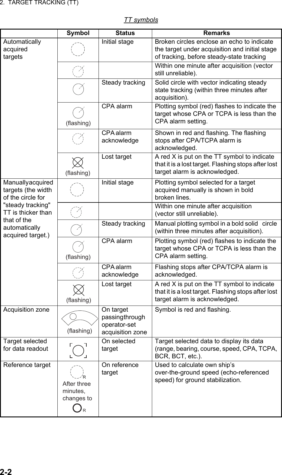
![2. TARGET TRACKING (TT)2-32.2 How to Acquire and Track TargetsThis radar can acquire a maximum of 100 targets, the number of automatically and manually acquired targets determined by the [TT TARGET MENU] setting.1. Right-click the [TT] icon to show the [TT TARGET MENU] window.2. Click [TT SELECT] then the distribution between manually and automatically acquired targets.[MANUAL 100]: 100 for manual tracking[AUTO 25]: 25 for automatic tracking, 75 for manual tracking[AUTO 50]: 50 for automatic and manual tracking[AUTO 75]: 75 for automatic tracking, 25 for manual tracking[AUTO 100]: 100 for automatic tracking3. Click outside the menu window to close the menu.2.3 Manual AcquisitionYou can acquire targets manually as follows:1. Right-click anywhere in the radar display to open [CURSOR MENU].2. Click [ACQUIRE].3. Click the target to acquire. You can select several targets by clicking consecutively.4. Right-click to quit. [TT TARGET MENU]1 BACK2 TT SELECT MANUAL 100/ AUTO 25/ AUTO 50/ AUTO 75/ AUTO 1003 ALL CANCEL NO /YES4 REF TT VECTOR OFF/ON5 ACK LOST TARGETS NO/YES6 [TT LOST FILTER] [CURSOR MENU]1 BACK2 ACQUIRE3 REF MARK4 OFFCENTER5 EBL OFFSETEchoEchoAcquiredClick](https://usermanual.wiki/Furuno-USA/9ZWRTR102.Users-Manual-4/User-Guide-3763531-Page-17.png)
![2. TARGET TRACKING (TT)2-42.4 Automatic AcquisitionTargets which enter an acquisition zone (two zones possible) are automatically acquired. Set an acquisition area as follows:2.4.1 How to set an acquisition zoneNote: The acquisition zone can not be set within 3 NM from own ship. 1. Click the [AZ1] icon. The [AZ1] icon now reads "AZ1 SET".2. Click the point A.3. Click the point B. The [AZ1] icon now reads "AZ1 WORK".Note: [AZ2] can be set when [AZ1] is active. The dashed lines are longer on [AZ2].2.4.2 How to sleep an acquisition zone1. Click the appropriate [AZ] icon.2. Click the [AZ] icon to change from [AZ1 (2) WORK] to [AZ1 (2) SLP]. The acquisition zone disappears from the screen. To reactivate and display the acquisition zone, repeat this procedure to display [AZ1 (2) WORK].2.4.3 How to delete an acquisition zone1. Click the appropriate [AZ] icon.2. Press and hold down the left button until the [AZ] icon goes blank. The acquisition zone is deleted from the screen.Note: If both acquisition zones are the active [AZ1] can not be deleted unless the [AZ2] is deleted.[AZ1]: Acquisition zone 1 “SET” appears.[AZ1 ]: No acquisition zone.[AZ1 SET ]: Set acquisition zone.[AZ1 WORK ]: Activate acquisition zone.[AZ1 SLP ]: Sleep acquisition zone.Acquisition zone statusRL 2-3 ►HONTAZ1 ►AZ2 ►ALR1 ►ALR2 ►TTON ►LIST EBL1 12GRNBLKD-GRNDOCK OFFRL 2-3 ►HONTAZ1 SET ►AZ2 ►ALR1 ►ALR2 ►TTON ►LIST EBL1 12GRNBLKD-GRNDOCK OFFClickABTarget in acquisition zone is red and flashing.](https://usermanual.wiki/Furuno-USA/9ZWRTR102.Users-Manual-4/User-Guide-3763531-Page-18.png)
![2. TARGET TRACKING (TT)2-52.4.4 Acquisition zone reference1. Open [MAIN MENU], click [TT.AIS].2. Click [ACQUIRE ZONE].3. Click [AZ STAB] then the acquisition zone reference as appropriate.[STAB NORTH]: Acquisition zone is fixed to North.[STAB HEADING]: Acquisition zone keeps position related to your ship.4. Click [POLYGON STAB] then the acquisition zone shape and stabilization as appropriate.[OFF]: Acquisition zone is a sector; number of points is limited to four. Stabilized against land.[STAB GND]: Polygon having 3-10 points. Stabilized against ground.[STAB NORTH]: Polygon having 3-10 points. Stabilized against north.[STAB HEADING]: Polygon having 3-10 points. Stabilized against heading.5. Click outside the menu window to close the menu.2.5 How to Stop Tracking a TargetYou can stop tracking specific targets or all targets.How to cancel tracking on individual targets1. Place the cursor (+) on the target. The mark (×) flashes behind the target.2. Right-click the target to show the [TT] window.3. Click [TARGET CANCEL] to stop tracking the target.How to stop tracking all targets1. Right-click the [TT] icon to show the [TT TARGET MENU].2. Click [ALL CANCEL].3. Click [YES].4. Click outside the menu window to close the menu. [ACQUIRE ZONE]1 BACK2 AZ STAB STAB NORTH/ STAB HEADING3 POLYGON STAB OFF/STAB GND/ STAB NORTH/ STAB HEADING [TT]1 BACK2 TARGET DATA3 TARGET CANCELPlace the cursor (+).Right-clickFlashing mark (×), with TT number01 [TT TARGET MENU]1 BACK2 TT SELECT MANUAL 100/ AUTO 25/ AUTO 50/ AUTO 75/ AUTO 1003 ALL CANCEL NO /YES4 REF TT VECTOR OFF/ON5 ACK LOST TARGETS NO/YES6 [TT LOST FILTER]](https://usermanual.wiki/Furuno-USA/9ZWRTR102.Users-Manual-4/User-Guide-3763531-Page-19.png)
![2. TARGET TRACKING (TT)2-62.6 TT Symbol Attributes2.6.1 TT symbol brilliance1. Right-click the [BRL] icon to show the [BRILL MENU] window.2. Click [EDIT].3. Click [BRILL DETAIL] to show the [BRILL DETAIL] window.4. Click [TT SYMBOL].5. Click the slide bar for [TT SYMBOL] then set the brilliance as appropriate with the setting knob.6. Click outside the menu window to close the menu.2.6.2 TT symbol colorYou may select the color of the TT symbol as follows.1. Open [MAIN MENU], click [TT.AIS].2. Click [SYMBOL].3. Click [TT].4. Click [SYMBOL COLOR].5. Click the desired color.[GRN]: green, [BLU]: blue, [CYA]: cyan, [MAG]: magenta, [WHT]: white6. Click outside the menu window to close the menu.(at the bottom left corner on the screen)Right-clickBRL 2-3 ►ECHOB-INOUTMONIPANLAZ1 ►AZ2 ►ALR1 ►ALR2 ► HL OFFTTON > GRNBLKD-GRN5015 [BRILL MENU]1 BACK2 [EDIT]3 [PRESET] [BRILL DETAIL]1 BACK2 CHARACTER 3 CURSOR4 ECHO 5 TRAIL6 HEADING LINE 7 FIXED RING 8 GYRO RING 9 EBL 10 VRM11 TT SYMBOL12 AIS SYMBOL 11 MARK/LINE Click [TT]1 BACK2 SYMBOL COLOR GRN/BLU/CYA/MAG/WHT [SYMBOL]1 BACK2 [TT]3 [AIS]](https://usermanual.wiki/Furuno-USA/9ZWRTR102.Users-Manual-4/User-Guide-3763531-Page-20.png)
![2. TARGET TRACKING (TT)2-72.7 Lost TargetTargets not detected in five consecutive scans become "lost targets." A lost target is shown in the display with a flashing red "X". Flashing stops after the lost target alarm is acknowledged.If you are in an area where tracked targets are lost fre-quently you may want to disable the lost target alarm against tracked targets by maximum range or minimum speed.2.7.1 Lost target filterYou can set the lost target alarm to sound against lost TTs that meet a specific range or ship speed. Set the criteria as shown below.1. Right-click the [TT] icon.2. Click [TT LOST FILTER].3. Click [TT LOST FILTER].4. Select how to enable or disable the lost target alarm.[OFF]: Disable the alarm.[FILT]: Get the alarm against the targets whose criteria meet the settings on the [TT LOST FILTER] menu.[ALL]: Get the alarm against all lost targets.5. Click [MAX RANGE VALUE] and [MIN SHIP SPEED VALUE] as appropriate, referring to the description below.[MAX RANGE], [MAX RANGE VALUE]: Any TT lost target beyond the range set here will not trigger the lost target alarm.[MIN SHIP SPEED], [MIN SHIP SPEED VALUE]: Any TT lost target slower than this setting will not trigger the lost target alarm.Note: Reference targets are not affected by this filter.2.7.2 How to acknowledge a lost target1. Right-click the [TT] icon to show [TT TARGET MENU]. 2. Click [ACK LOST TARGETS].3. Click [YES]. All lost targets disappear from the screen.Lost target(flashing) [TT TARGET MENU]1 BACK2 TT SELECT MANUAL 100/ AUTO 25/ AUTO 50/ AUTO 75/ AUTO 1003 ALL CANCEL NO /YES4 REF TARGET VECTOR OFF/ON5 ACK LOST TARGETS NO/YES6 [TT LOST FILTER] [TT LOST FILTER]1 BACK2 TT LOST FILTER OFF/FILT/ALL3 MAX RANGE OFF/ON4 MAX RANGE VALUE 03.0 NM5 MIN SHIP SPEED OFF/ON6 MIN SHIP SPEED VALUE 00.0kn](https://usermanual.wiki/Furuno-USA/9ZWRTR102.Users-Manual-4/User-Guide-3763531-Page-21.png)
![2. TARGET TRACKING (TT)2-82.8 TT DataThe TT target list provides a comprehensive data display of all TT targets being tracked.How to display TT data1. Place the cursor (+) on the target to show the target data. The mark (×) flashes behind the target.2. Right-click the target to show the [TT] window.3. Click [TARGET DATA] to show the [TT INFO] window. The selected target is enclosed in a broken square.[TT INFO] window4. Click outside the menu window to close the menu.[NO.]: Target No. [COG]: Course over ground[RNG]: Range [CPA]: Target’s CPA[BRG]: Bearing [TCPA]: Target’s TCPA[SOG]: Speed over ground [TT]1 BACK2 TARGET DATA3 TARGET CANCELTarget, with broken square01[TT INFO]NO. : 001RNG : 35. 7NMBRG : 036. 0° TSOG : 5. 2knCOG : 324. 0° TCPA : 3. 15NMTCPA : 52m30s](https://usermanual.wiki/Furuno-USA/9ZWRTR102.Users-Manual-4/User-Guide-3763531-Page-22.png)
![2. TARGET TRACKING (TT)2-92.9 TT ListHow to display the TT listThe TT list provides the range, bearing, CPA and TCPA of all tracking targets.To display the TT list, click the [LIST] icon for TT at the bottom left corner on the screen to show the [TT LIST] window.To close the [TT LIST] window, click the close button at the top right corner of the window.[No.]: Target number[RANGE], [BEARING]: Range and Bearing from own ship to the selected target with suffix "T" (True) or "R" (Relative).[CPA], [TCPA]: CPA (Closest Point of Approach) is the closest range a target will approach to own ship. TCPA is the time to CPA. Both CPA and TCPA are automatically calculated. A negative TCPA value means that you have already passed the CPA and the target is going away from own ship.How to display TT dataClick the target on [TT LIST] to show the [TT INFO] window. See section 2.8.How to sort the TT listYou may sort the TT list by RANGE, CPA, TCPA as follows.1. Right-click the [LIST] icon for TT to show the [TT-LIST] window.2. Click [SORT BY].3. Click the sorting item desired, by [RANGE], [CPA] or [TCPA].4. Click outside the menu window to close the menu.BRL 2-3 ►ECHOB-INOUTMONIPANLAZ1 ►AZ2 ►ALR1 ►ALR2 ► HL OFFTTON ►LIST ►EBL1 123.4°> EBL2 82.9°NAV 0.160TTNMGRNBLKD-GRN5015[LIST] icon for TT[TT LIST]No. RANGE BEARING CPA TCPA001 9. 60NM 058. 8°T 0. 00NM 00m00s002 19. 2NM 059. 0°T 0. 00NM 00m00sTT listClose buttonPage up buttonPage down buttonClick [TT-LIST]1 BACK2 SORT BY RANGE /CPA/TCPA](https://usermanual.wiki/Furuno-USA/9ZWRTR102.Users-Manual-4/User-Guide-3763531-Page-23.png)
![2. TARGET TRACKING (TT)2-102.10 Vector ModesTarget vectors can be displayed relative to own ship's heading (Relative) or north (True).2.10.1 Description of vectorsSea stabilization is a mode where own ship and all targets are referenced to the sea using a compass heading and single-axis log water speed inputs. Ground stabilization is a mode where own ship and all targets are referenced to the ground using the ground track or set and drift inputs. If the accuracy seems unsatisfactory, enter set and drift corrections.True vectorOwn ship and other ships move on the display at their true speeds and courses. This mode is useful for distinguishing moving targets from stationary ones.Relative vectorOther ships move relative to your ship. This mode is useful for finding ships on a collision course with your ship. A ship whose vector passes through your ship's position is on a collision course.2.10.2 Vector mode and lengthVectors may be displayed in true or relative mode. Vector time (or the length of vectors) can be set from 30 sec, 1 to 6 minutes.1. Open [MAIN MENU], click [TT.AIS].2. Click [VECTOR].3. Click [VECTOR MODE].4. Click the appropriate mode.[VECTOR REL]: Relative mode[VECTOR T-G], [VECTOR T-S]: True mode5. Click [VECTOR TIME].6. Select the time (30 sec to 6 min) with the setting knob.7. Click outside the menu window to close the menu.True vectors in head-up mode Relative vectors in head-up modeBOwn shipABOwn shipBuoy BuoyTarget on collision courseTarget on collision courseA [VECTOR]1 BACK2 VECTOR MODE VECTOR REL/VECTOR T-G*3 VECTOR TIME 30sec*: For SOG, [VECTOR T-G]For STW, [VECTOR T-S]](https://usermanual.wiki/Furuno-USA/9ZWRTR102.Users-Manual-4/User-Guide-3763531-Page-24.png)
![2. TARGET TRACKING (TT)2-112.11 Past Position DisplayEqually time-spaced dots shows the past position display marking the past positions of any targets being tracked.A new dot is added every minute (or at other preset time intervals) until the preset number is reached. If a target changes its speed, the spacing will be uneven. If it changes the course, its plotted course will not be a straight line.Past position orientation, true or relative, is controlled with [TRAIL MODE] in the [TRAIL] menu. See section 1.25 for the procedure.2.11.1 How to select the dot number and interval of the past positionYou may select the number of past points to display per plotting interval as follows.1. Open [MAIN MENU], click [TT.AIS].2. Click [PAST POSN].3. Click [INTERVAL].4. Click the plot interval desired (0.5 min to 6 min). Click [OFF] to erase all past position points and deactivate the past position display.5. Click [POINTS].6. Click the number of dots to display, 5 or 10. 7. Click outside the menu window to close the menu.2.11.2 Past position display modeThe display mode for the past position display is the same as that set for the TT vector. In the true motion mode, the true vector is displayed. See paragraph 2.10.1.(a) Ship turning (b) Ship running straight (c) Ship reduced speed(d) Ship increased speed [PAST POSN]1 BACK2 INTERVAL OFF/0.5min/1min/2min/ 3min/6min3 POINTS 5/10](https://usermanual.wiki/Furuno-USA/9ZWRTR102.Users-Manual-4/User-Guide-3763531-Page-25.png)
![2. TARGET TRACKING (TT)2-122.12 CPA/TCPA AlarmThe CPA/TCPA alarm alerts you when both the CPA and TCPA of a TT is within a defined limit.CPA and TCPA of the target is less than the alarm settings.1. Open [MAIN MENU], click [ALARM].2. Click [TT.AIS].3. Click [CPA LIMIT].4. Click [CPA LIMIT].5. Click [ON].6. Click [RANGE].7. Select the desired distance for CPA (Setting range: 0.1 to 24 NM) with the setting knob.8. Click [TIME].9. Select the desired time for TCPA (Setting range: 30 sec to 15 min) with the setting knob.10. Click outside the menu window to close the menu. [CPA LIMIT]1 BACK2 CPA LIMIT OFF/ON3 RANGE 01. 0NM4 TIME 30sec [TT•AIS]1 BACK2 [CPA LIMIT] Click](https://usermanual.wiki/Furuno-USA/9ZWRTR102.Users-Manual-4/User-Guide-3763531-Page-26.png)
![3-13. AIS OPERATIONThe AIS (Automatic Identification System) transponder connected to this radar exchanges all data and information required by the SOLAS 1994 with other AIS-fitted ships. AIS information is graphically indicated together with the radar and TT information.When AIS is active, manual or reference speed selection is not available.AIS Function On/OffYou may disable or enable the AIS function from the AIS icon. Long press the AIS icon with the left button to switch function between on and off.3.1 AIS Display On/OffTo show or hide the AIS display, click the [AIS] icon at the bottom right corner on the screen.When the AIS is turned on, AIS targets are marked with appropriate AIS symbol as shown in the table below.Note: If the CPA/TCPA alarm is generated while the setting is [AIS OFF], the AIS target is automatically displayed and the setting in the [AIS] box becomes [AIS ALL].[AIS OFF]: All AIS symbols are hidden, but tracking continues internally.[AIS FIL]: AIS targets are displayed according to the criteria set with [CPA AUTO ACTIVE] in [AIS TARGET MENU]. See section 3.10 for details.[AIS ALL]: All AIS targets received by the AIS transponder are displayed with symbols.(at the bottom right corner on the screen)RM1 1.567RM2 0.1600 160NMLISTNMNMMANMANMANTUNE MANGAINSTCRAINIR ES EAVTRAIL2.50sec01m05sRELONAIS– – –AIS– – –[AIS] iconAIS– – –► AISFIL► AIS Function “Off” AIS Function “On”AISALL► AISOFF► Show the filtered AIS targets.Show all AIS targets. Hide all AIS targets. AISOFF►AISOFF►AISFIL►AISFIL►AISALL►AISALL►Click ClickClick](https://usermanual.wiki/Furuno-USA/9ZWRTR102.Users-Manual-4/User-Guide-3763531-Page-27.png)
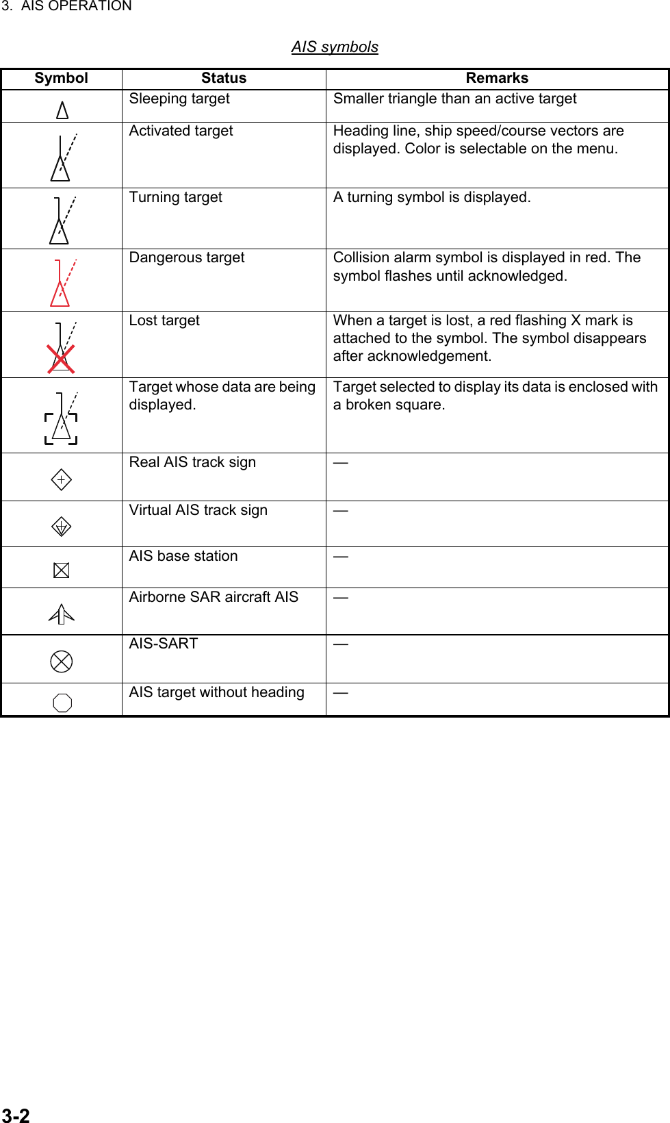
![3. AIS OPERATION3-3AIS symbols with Blue sign, Blue conesNote 1: The equipment continues to process AIS targets when the AIS feature is switched off. When the AIS is again turned on, symbols are immediately displayed.Note 2: AIS symbols are momentarily erased after the screen is redrawn when the orientation mode is changed from the head-up mode.Note 3: When no AIS data is received, the message "AIS RECEIVE ERROR" appears. Check the AIS transponder.Note 4: An AIS target is declared as lost target if it is not detected in five consecutive reporting periods.3.2 AIS Display FilterIf there are too many AIS targets on the screen you may wish to remove unnecessary ones. You may remove targets by distance from own ship, speed, class and length. For example, you might want to remove slow moving targets, as they normally do not require close monitoring.1. Right-click the [AIS] icon.2. Click [AIS DISP FILTER].Blue signNot connected or not available Not set SetThe number of Blue conesNo 1 to 3(Red mark) No 1 to 3(Red mark) No 1 to 3(Red mark)With heading Without heading(Scaled symbol)(Scaled symbol)(Scaled symbol)(Scaled symbol)(Scaled symbol)(Scaled symbol) [AIS TARGET MENU]1 BACK2 SLEEP ALL TARGETS NO/YES3 ACTIVATE ALL TARGETS NO/YES4 ACK LOST TARGETS NO/YES5 [AIS DISP FILTER]6 [CPA AUTO ACTIVATE]7 [AIS LOST FILTER] [AIS DISP FILTER]1 BACK2 AIS DISP FILTER OFF/FILT/ALL3 CLASS A OFF/ON4 CLASS B OFF/ON5 BASE STATION OFF/ON6 MIN RANGE OFF/ON7 MIN RANGE VALUE 00.4km8 MAX RANGE OFF/ON9 MAX RANGE VALUE 03.0km10 MIN SHIP SPEED OFF/ON11 MIN SHIP SPEED VALUE 00.0km/h12 MIN SHIP LENGTH OFF/ON13 MIN SHIP LENGTH VALUE 000m](https://usermanual.wiki/Furuno-USA/9ZWRTR102.Users-Manual-4/User-Guide-3763531-Page-29.png)
![3. AIS OPERATION3-43. Set item 3 to 13 referring to the description below.[CLASS A]: Hide or show the CLASS A AIS targets.[CLASS B]: Hide or show the CLASS B AIS targets.[BASE STATION]: Hide or show AIS base stations.[MIN RANGE], [MIN RANGE VALUE]: If [MIN RANGE] is set to [ON], only AIS targets further than the range set at [MIN RANGE VALUE] are shown.[MAX RANGE], [MAX RANGE VALUE]: If [MAX RANGE] is set to [ON], only AIS targets nearer than the range set at [MAX RANGE VALUE] are shown.[MIN SHIP SPEED], [MIN SHIP SPEED VALUE]: If [MIN SHIP SPEED] is set to [ON], only AIS targets faster than the speed set at [MIN SHIP SPEED VALUE] are shown.[MIN SHIP LENGTH], [MIN SHIP LENGTH VALUE]: If [MIN SHIP LENGTH] is set to [ON], only AIS targets longer than the length set at [MIN SHIP SPEED VALUE] are shown.4. Click outside the menu window to close the menu.Note: An AIS target whose data is currently displayed is not affected by the filter setting.3.3 How to Activate Targets3.3.1 How to activate specific targets manuallyWhen you convert a sleeping target to an activated target, the target’s course and speed are shown with a vector. You can easily judge target movement by monitoring the vector.Sleeping targets within an acquisition zone are automatically changed to activated targets and are colored red. See section 3.5 for details.1. Right-click the [AIS] icon to activate to show the AIS window.2. Click [ACTIVE/SLEEP].3. Click outside the menu window to close the menu.3.3.2 How to activate all targets1. Open [AIS TARGET MENU] (see step 1 of section 3.2), click [ACTIVATE ALL TARGETS].2. Click [YES].3. Click outside the menu window to close the menu. [AIS]1 BACK2 TARGET DATA3 ACTIVE/SLEEPHeading lineTurning direction (ROT)*: Vector shows STW (speed through water) and CSE (course) when water tracking mode is selected at the radar.SOG (Speed over Ground) and COG (Course over Ground) vector*](https://usermanual.wiki/Furuno-USA/9ZWRTR102.Users-Manual-4/User-Guide-3763531-Page-30.png)
![3. AIS OPERATION3-53.4 How to Sleep Targets3.4.1 How to sleep an individual targetYou may “sleep” an AIS target as below when the screen becomes filled with targets, which might prevent important radar and AIS displays from being identified. Note that targets that have been activated automatically cannot be “slept”.1. Right-click the AIS target to sleep to show the AIS window.2. Click [ACTIVE/SLEEP].3.4.2 How to sleep all targets1. Open [AIS TARGET MENU] (see step 1 of section 3.2), click [SLEEP ALL TARGETS].2. Click [YES].3. Click outside the menu window to close the menu.3.5 AIS Symbol AttributesYou may adjust the brilliance and select the size and color of the AIS symbol.3.5.1 AIS symbol brilliance1. Right-click the [BRL] (brill) icon to show the [BRILL MENU] window.2. Click [EDIT].3. Click [BRILL DETAIL] to show the [BRILL DETAIL] window.4. Click [AIS SYMBOL].5. Set the brilliance as appropriate with the setting knob.6. Click outside the menu window to close the menu.3.5.2 AIS symbol size and colorYou may select the size and color of the AIS symbol as follows.1. Open [MAIN MENU], click [TT.AIS].2. Click [SYMBOL].Active AIS Sleeping AIS [BRILL DETAIL]1 BACK2 CHARACTER 3 CURSOR4 ECHO 5 TRAIL6 HEADING LINE 7 FIXED RING 8 GYRO RING 9 EBL 10 VRM11 TT SYMBOL12 AIS SYMBOL 11 MARK/LINE](https://usermanual.wiki/Furuno-USA/9ZWRTR102.Users-Manual-4/User-Guide-3763531-Page-31.png)
![3. AIS OPERATION3-63. Click [AIS] to show the [AIS] window.4. Click [SYMBOL COLOR] then the de-sired color.5. Click [SCALED SYMBOL].6. Click [OFF] or [ON] as appropriate.[OFF]: All AIS symbols shown in same size.[ON]: All AIS symbols are scaled according to ships’ lengths.7. Click outside the menu window to close the menu.3.6 Past Position DisplayThe past position display shows equally time-spaced dots marking past positions of activated AIS targets. A new dot is added at preset time intervals until the preset number is reached. If a target changes its speed, the spacing is be uneven. If it changes course, its plotted course is not shown by a straight line.3.6.1 How to select the number and interval of the past positionYou may select the number of past points to display per plotting interval as follows.1. Open [MAIN MENU], click [TT.AIS].2. Click [PAST POSN].3. Click [INTERVAL].4. Click the plot interval desired (0.5 min to 6 min). Click [OFF] to erase all past position points and deactivate the past position display.5. Click [POINTS].6. Click the number of dots to display, 5 or 10. 7. Click outside the menu window to close the menu. [AIS]1 BACK2 SYMBOL COLOR GRN/BLU/CYA/MAG/WHT3 ROT TAG LIMIT 000.1deg/min4 SCALED SYMBOL OFF/ON(a) Ship turning (b) Ship running straight (c) Ship reduced speed (d) Ship increased speed [PAST POSN]1 BACK2 INTERVAL OFF/0.5min/1min/2min/ 3min/6min3 POINTS 5/10](https://usermanual.wiki/Furuno-USA/9ZWRTR102.Users-Manual-4/User-Guide-3763531-Page-32.png)