Furuno USA 9ZWRTR102 Transceiver for Radar User Manual OME 36700 A
Furuno USA Inc Transceiver for Radar OME 36700 A
UserManual.wiki
>
Furuno USA
>
9ZWRTR102 User Manual
>
Users Manual 5
Contents
1.
Users Manual 1
2.
Users Manual 2
3.
Users Manual 3
4.
Users Manual 4
5.
Users Manual 5
Users Manual 5
Navigation menu
Upload a User Manual
Namespaces
Wiki Guide
HTML
PDF
Info
Views
User Manual
Discussion / Help
Navigation
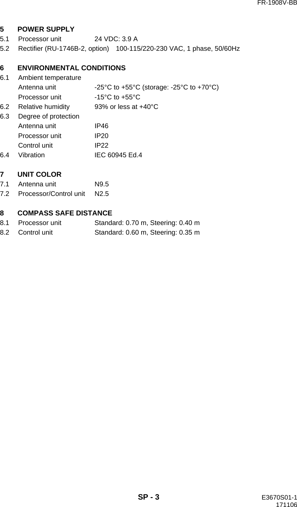
![3. AIS OPERATION3-73.7 Lost TargetWhen AIS data is not received from a target within 3-5 report intervals (see Note 2), the target symbol changes to the lost target symbol (flashing). No audio or visual alarm is given for a lost target.Note: The AIS data transmission interval depends on target’s speed. For example, the data is transmitted every 10 seconds on ship speed of 0 to 14 knots and every two seconds on the ship speed of more than 23 knots. For details see the operator’s manual of the AIS transponder.3.7.1 Lost target filterIf there are a lot of AIS targets in your area, the lost target alarm may sound frequently. In this case you may wish to have the alarm ignore lost targets whose range, speed, class or length are below the threshold value you specify.1. Right-click the [AIS] icon to show [AIS TARGET MENU].2. Click [AIS LOST FILTER].3. Click [AIS LOST FILTER] in the [AIS LOST FILTER] menu.4. Click the target alarm to enable.[OFF]: Disable the alarm.[FILT]: Get the alarm against the targets whose criteria meet the settings on the [AIS LOST FILTER] menu.[ALL]: Get the alarm against all lost targets.5. Click [MAX RANGE VALUE] and [MIN SHIP SPEED VALUE] as appropriate, referring to the description below.[MAX RANGE], [MAX RANGE VALUE]: Any AIS lost target beyond the range set here is not shown.[MIN SHIP SPEED], [MIN SHIP SPEED VALUE]: Any AIS lost target slower than this setting is not shown.[EXCEPT CLASS B]: Select [ON] to prevent trigger lost Class B AIS lost target.[MIN SHIP LENGTH], [MIN SHIP LENGTH VALUE]: Any AIS lost target whose length is shorter than this setting is not shown.3.7.2 How to acknowledge a lost target1. Click the [AIS] icon to show [AIS TARGET MENU].2. Right-click [ACK LOST TARGETS].3. Click [YES]. The lost target disappears from the screen.Activated target Lost target [AIS TARGET MENU]1 BACK2 SLEEP ALL TARGETS NO/YES3 ACTIVATE ALL TARGETS NO/YES4 ACK LOST TARGETS NO/YES5 [AIS DISP FILTER]6 [CPA AUTO ACTIVATE]7 [AIS LOST FILTER] [AIS LOST FILTER]1 BACK2 AIS LOST FILTER OFF/FILT/ALL3 MAX RANGE OFF/ON4 MAX RANGE VALUE 03.0km5 MIN SHIP SPEED OFF/ON6 MIN SHIP SPEED VALUE 00.0km/h7 EXCEPT CLASS B OFF/ON8 MIN SHIP LENGTH OFF/ON9 MIN SHIP LENGTH VALUE 000mClick](https://usermanual.wiki/Furuno-USA/9ZWRTR102.Users-Manual-5/User-Guide-3763532-Page-1.png)
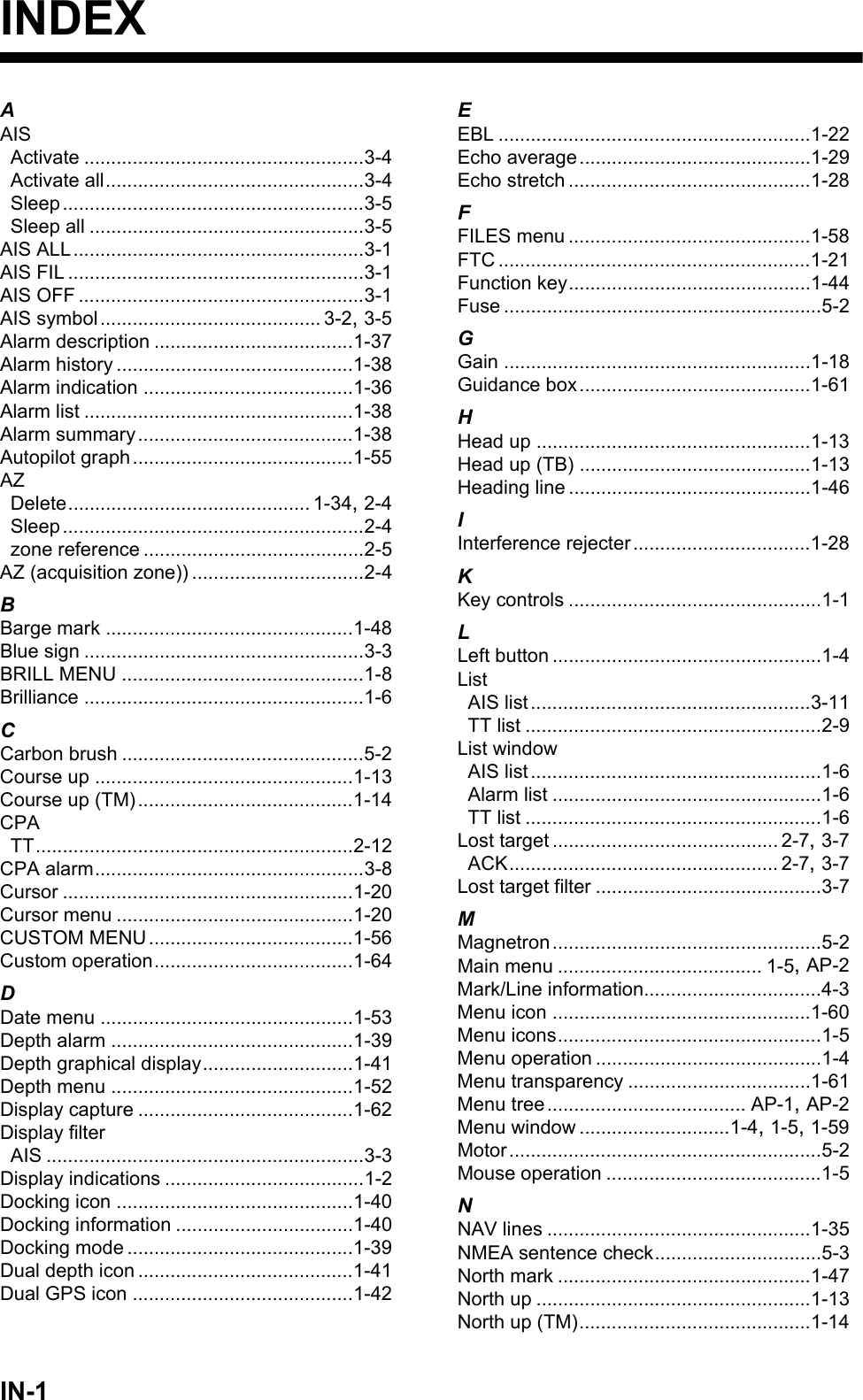
![3. AIS OPERATION3-83.8 ROT SettingYou may set the lower limit of the ROT (Rate Of Turn) at which the heading line on target symbols points the ship’s turning direction.1. Open [MAIN MENU], click [TT.AIS].2. Click [SYMBOL].3. Click [AIS].4. Click [ROT TAG LIMIT].5. Click the setting value then enter ROT with the setting knob (setting range: 0.1 to 720.0 (deg/min)).6. Click outside the menu window to close the menu.3.9 CPA/TCPA AlarmThe AIS continuously monitors the predicted range at the Closest Point of Approach (CPA) and predicted time to CPA (TCPA) of each AIS target. When the predicted CPA of an AIS target becomes smaller than a preset CPA range and its predicted TCPA less than a preset TCPA limit, the audio alarm sounds. In addition, the symbol of the offending AIS target is red and flashes together with its vector.CPA/TCPA alarm ranges must be set up properly taking into consideration the size, tonnage, speed, turning performance and other characteristics of own ship.The reference point for CPA, TCPA calculation may be selected from antenna position or conning position.To set this alarm, see section 2.12 "CPA/TCPA Alarm". [AIS]1 BACK2 SYMBOL COLOR GRN/BLU/CYA/MAG/WHT3 ROT TAG LIMIT 000.0deg/min4 SCALED SYMBOL OFF/ONShip turning to starboard](https://usermanual.wiki/Furuno-USA/9ZWRTR102.Users-Manual-5/User-Guide-3763532-Page-2.png)
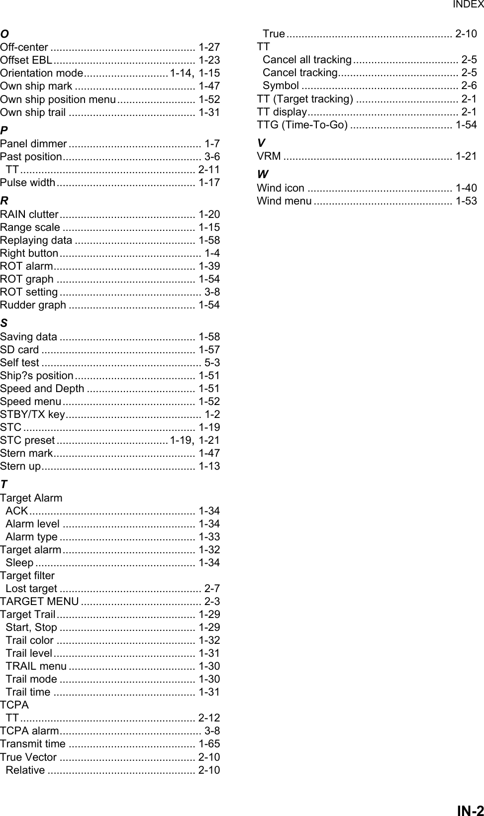
![3. AIS OPERATION3-93.10 Automatic Target ActivationYou can get automatic activation of a sleeping AIS target when its CPA is within the CPA/TCPA alarm setting. Further, you can select which AIS targets to automatically activate.1. Right-click the [AIS] icon to show the [AIS TARGET MENU] window.2. Click [CPA AUTO ACTIVATE].3. Click [CPA AUTO ACTIVATE].4. Click the activating mode for AIS target.[OFF]: Disable automatic activation of AIS target by CPA.[FILT]: Activate only the targets that fulfill the requirements set on the [CPA AUTO ACTIVATE] menu.[ALL]: For all targets.5. Set items 3 to 9 referring to the description below.[MAX RANGE], [MAX RANGE VALUE]: Any AIS target beyond the range set here will not be activated.[MIN SHIP SPEED], [MIN SHIP SPEED VALUE]: Any AIS target slower than this setting will not be activated.[EXCEPT CLASS B]: Select [ON] to prevent automatic activation of class B AIS targets.[MIN SHIP LENGTH], [MIN SHIP LENGTH VALUE]: Any AIS target whose length is shorter than this setting will not be activated.6. Click outside the menu window to close the menu. [AIS TARGET MENU]1 BACK2 SLEEP ALL TARGETS NO/YES3 ACTIVATE ALL TARGETS NO/YES4 ACTIVATE ALL TARGETS NO/YES5 [AIS DISP FILTER]6 [CPA AUTO ACTIVATE]7 [AIS LOST FILTER] [CPA AUTO ACTIVATE]1 BACK2 CPA AUTO ACTIVATE OFF/FILT/ALL3 MAX RANGE OFF/ON4 MAX RANGE VALUE 03.0km5 MIN SHIP SPEED OFF/ON6 MIN SHIP SPEED VALUE 00.0km/h7 EXCEPT CLASS B OFF/ON8 MIN SHIP LENGTH OFF/ON9 MIN SHIP LENGTH VALUE 000m](https://usermanual.wiki/Furuno-USA/9ZWRTR102.Users-Manual-5/User-Guide-3763532-Page-3.png)
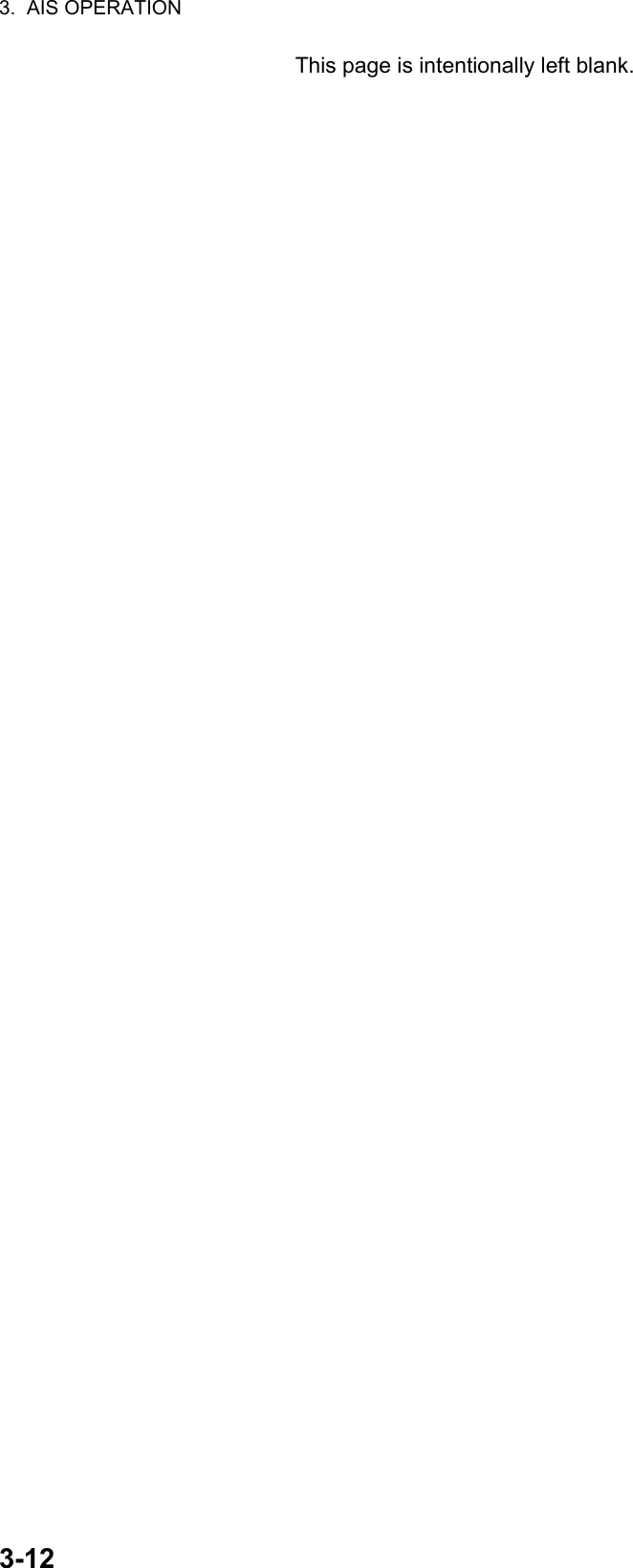
![3. AIS OPERATION3-103.11 AIS Target DataYou may display an AIS target’s data by selecting it on the display. This data is shown for the activated AIS target only. The selected AIS target is enclosed in a broken square. The target data is shown on the [AIS INFO] window.[AIS INFO] windowSymbol operationLeft-click the AIS target to show the selected target's information window.Menu operation1. Right-click the AIS target to show the [AIS] window.2. Click [TARGET DATA] to show the [AIS INFO] window.3. Click the close button or outside the information window to close the menu.[NAME]: Name of ship [RNG/BRG]: Range/Bearing to target[FLAG]: Flag state [SOG/COG] (or [STW/CTW]): Target’s speed and course[CALL SIGN]: Call sign[MMSI]: MMSI No. [CPA/TCPA]: Target’s CPA/TCPA[IMO NO.]: IMO No. [HDG]: Heading[LAT]: Latitude [ROT]: Rate of turn[LON]: Longitude [LEN/BEAM]: Ship’s length/Beam[BLUE SIGN]: Blue sign statusAIS Selected AIS to display the information[AIS INFO]NAME :XXXXFLAG :NETHERLANDSCALL SIGN :PFXXXXMMSI :123456789IMO NO. :missingLAT :51°53.661’ NLON :004°18.376’ ERNG/BRG :0.77km/324.4°RSOG/COG :11.1km/h/100.0°TCPA/TCPA :0.49km/03m10sHDG :missingROT :missingLEN/BEAM :135m/14.0mBLUE SIGN :NO [AIS]1 BACK2 TARGET DATA3 ACTIVE/SLEEP](https://usermanual.wiki/Furuno-USA/9ZWRTR102.Users-Manual-5/User-Guide-3763532-Page-4.png)
![3. AIS OPERATION3-113.12 AIS ListThe AIS list provides a comprehensive information about all AIS targets being tracked.How to display the AIS listClick the [LIST] icon for AIS at the bottom right corner on the screen.You can see [MMSI] and [NAME] for AIS targets. To close the [AIS LIST] window, click the close button on the list.How to display AIS target dataClick the target on [AIS LIST] to show the [AIS INFO] window. See section 3.11.How to sort the target listYou may sort the target list by RANGE, CPA, TCPA. Also, you can sort in ascending or descending order.1. Right-click the [LIST] icon for AIS to show the [AIS-LIST] window.2. Click [SORT BY].3. Click the sorting method desired.[NAME-UP], [NAME-DOWN]: Sort by name[RANEG-UP], [RANGE-DOWN]: Sort by range[CPA-UP], [CPA-DOWN]: Sort by CPA[TCPA-UP], [TCPA-DOWN]: Sort by TCPA4. Click outside the menu window to close the menu.Close button[AIS LIST] <SORT>NAME-UP 1/1MMSI NAME12XXXXXXXXX ABCXX2345XXXXXXX AXX[LIST] icon for AIS[LIST] icon for AISAIS listAISFLT►VRM1 1.567VRM2 0.160NAV 0 160NMLIST►NMNMMANMANMANAUTO01m013mRELONTUNEPage up buttonPage down buttonClick [AIS-LIST]1 BACK2 SORT BY NAME-UP /NAME-DOWN/ RANGE-UP/RANGE-DOWN/ CPA-UP/CPA-DOWN/ TCPA-UP/TCPA-DOWN[LIST] icon for AIS[LIST] icon for AISAISFLT►VRM1 1.567VRM2 0.160NAV0 160NMLIST►NMNMMANMANMANAUTO01m013mRELONTUNERight-click](https://usermanual.wiki/Furuno-USA/9ZWRTR102.Users-Manual-5/User-Guide-3763532-Page-5.png)
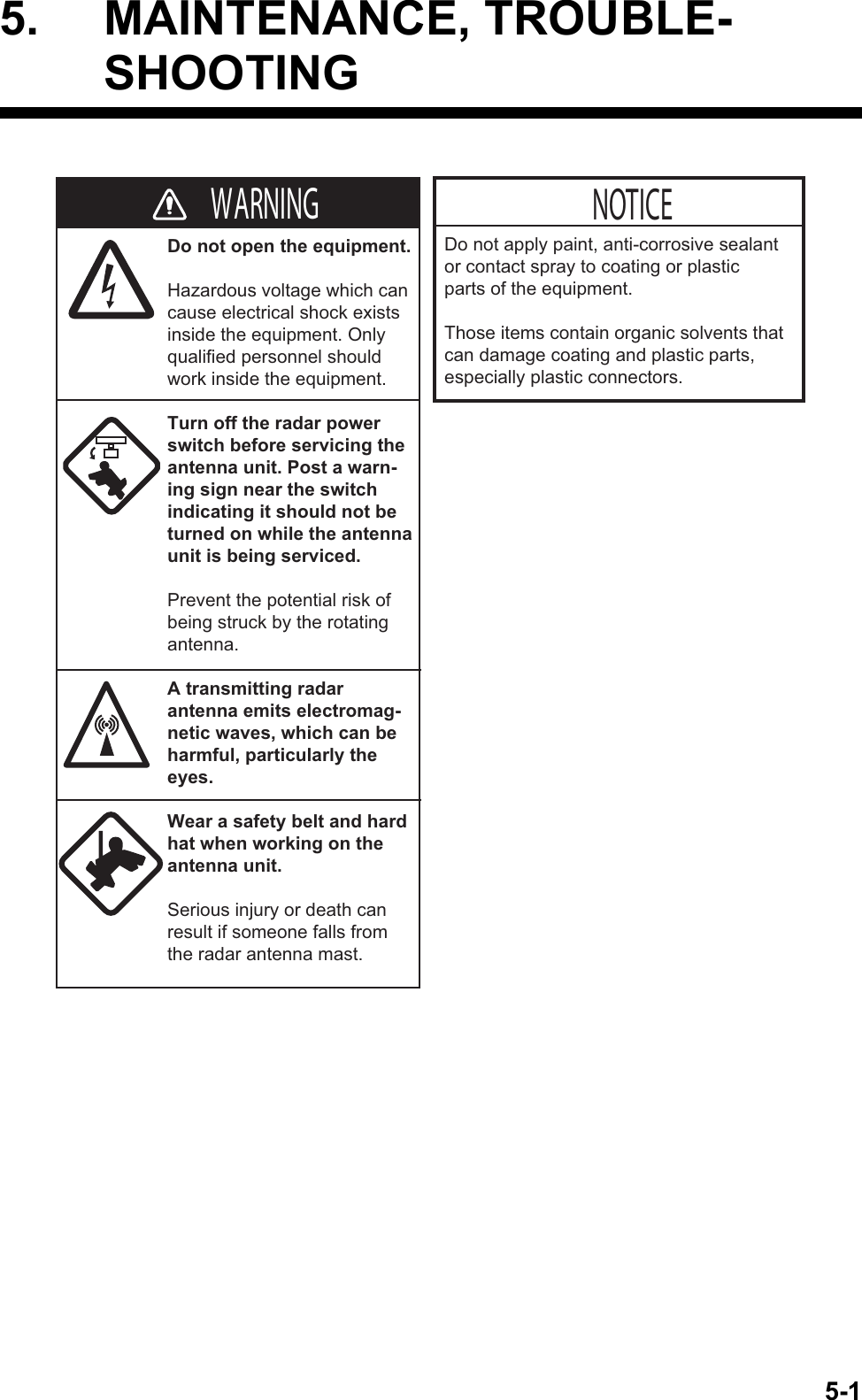
![4-14. RADAR MAP4.1 What is a Radar Map?The radar map feature, available in the [RIVER] mode, is a combination of map lines and symbols whereby the user can define and input the navigation, route planning and monitoring data on the screen. Map lines are a navigational facility whereby the observer can define lines to indicate channels or traffic separation schemes.The user can create a radar map on real-time base while using the radar for navigation or at leisure time at anchor. The map data is stored on the Flash ROM memory which is mounted on the main processor board.Note: Radar map function requires heading and positioning data.4.2 [MARK] iconThe [MARK] icon, located at the bottom left corner on the screen, is used to create marks and lines, line operations. This radar can save a total of 5,000 marks and lines.Navlines(by NAV LINE icon)Heading lineStern markApproximate coast lineXMark symbolsMark symbolsMENUBARGE ON2WHTONCYA DOCK OFFBRL2-3ECHOBINGRNBLKMARKMARKMark shape Color of the markDisplay icon [ON]: Shows all the marks currently selected at the [MARK] icon.[OFF]: Hides all marks currently selected at the [MARK] icon.[MARK] icon](https://usermanual.wiki/Furuno-USA/9ZWRTR102.Users-Manual-5/User-Guide-3763532-Page-7.png)
![4. RADAR MAP4-24.3 How to Enter Marks, Lines4.3.1 How to enter a mark, line with at the cursor position1. Click the mark color icon to select the re-quired color for the mark.2. Highlighting the [MARK] icon then rotate the setting knob to select a mark.3. Press the left button on the appropriate mark to decide the mark (or line) shape.MarksLines4. Press the left button. For lines, press the left button on the next point of the line then repeat this operation to complete the line.5. Press the right button to quit.MENUBARGE ON2WHTONCYA DOBRL2-3ECHOB-INGRNBLKMARKMARKMark color iconMENUBARGE ON2WHTOFFCYA DOBRL2-3ECHOB-INGRNBLKMARKMARK[MARK] iconTriangleLighthouse 1Lighthouse 2Lighthouse 3CircleSmall dotCrossFishSquareAnchorDotDash with 3 bar-lineDiamondDashed lineCoast lineContour line / Prohibited areasCableLong dashed line12345](https://usermanual.wiki/Furuno-USA/9ZWRTR102.Users-Manual-5/User-Guide-3763532-Page-8.png)
![4. RADAR MAP4-34.3.2 How to enter a mark by latitude and longitude position inputThis function is not available for entering lines.1. Right-click the [MARK] icon to show the [MARK ICON] window.2. Click [CREATE] to show the [CREATE] window.3. Click [ENTER BY LL]. 4. The cursor is on the far left-hand digit on the latitude line. Rotate the setting knob to click a numeral. The cursor moves to the next digit. Enter other numbers similarly.5. Right-click the last digit to finish.4.3.3 How to enter a mark at current positionThis function is not available for entering lines.1. Right-click the [MARK] icon to show the [MARK ICON] window.2. Click [OWN SHIP].4.4 Mark/Line informationYou can confirm the number of marks and lines which you have entered.1. Open [MAIN MENU], click [RADAR MAP].2. Click [MARK/LINE INFO] to open the information window. [MARK ICON]1 BACK2 [CREATE]3 OWN SHIP [CREATE]1 BACK2 ENTER BY LL 00°00. 000 N 000°00. 000 E3 CREATE [MARK/LINE INFO]1 BACK2 MARK/LINE INFO CURRENT NUMBER:100 TOTAL CAPACITY:5000](https://usermanual.wiki/Furuno-USA/9ZWRTR102.Users-Manual-5/User-Guide-3763532-Page-9.png)
![4. RADAR MAP4-44.5 How to Show, Hide Marks on the ScreenBy menu iconClick the mark display icon to show or hide the marks.By [DISPLAY] menuThis menu is available in the [RIVER] mode only.1. Open [MAIN MENU], click the [DISPLAY] menu.2. Click [MARK/LINE].3. Click [ON] or [OFF].4.6 How to Delete Marks, LinesHow to delete marks, lines individually1. Right-click the mark to delete.2. Click [DELETE]. 3. Click [YES].How to delete marks, lines by color, shape1. Open [MAIN MENU], click [RADAR MAP] to show the [RADAR MAP] menu.2. Click [DATA DELETE].Display icon: [ON] Display icon: [OFF]MENUBARGE ON2WHTONCYA DOCK OFFBRL2-3ECHOBINGRNBLKMARKMARKMENUBARGE ON2WHTOFFCYA DOCK OFFBRL2-3ECHOBINGRNBLKMARKMARKClick [MARK]1 BACK2 DELETE NO/YES 1 BACK2 MAP ALIGN OFF/ON3 [MARK/LINE INFO]4 [DATA DELETE] [RADAR MAP]1 BACK2 [MARK/LINE DELETE]3 [BARGE DELETE] [DATA DELETE]](https://usermanual.wiki/Furuno-USA/9ZWRTR102.Users-Manual-5/User-Guide-3763532-Page-10.png)
![4. RADAR MAP4-53. Click [MARK/LINE DELETE].4. Click the sort to delete. [SHAPE DELETE]: Select the shape to delete then select [YES] in [DELETE].[COLOR DELETE]: Select the color to delete then select [YES] in [DELETE].5. Click [DELETE].6. Click [YES].7. Click outside the menu window to close the menu.How to delete all marks, lines1. Open [MAIN MENU], click [RADAR MAP] to show the [RADAR MAP] menu.2. Click [DATA DELETE].3. Click [MARK/LINE DELETE].4. Click [MARK/LINE ALL DELETE].5. Click [YES].6. Click outside the menu window to close the menu.4.7 How to Align the Radar MapWhen the map is not overlaid on the radar picture correctly, you can align the map with the [MAP ALIGN] menu. 1. Open [MAIN MENU], click [RADAR MAP].2. Click [MAP ALIGN].3. Click [ON] to align the radar echo to the radar map. The cursor moves the center of the radar display. The mark symbols are moved in conjunction with the cursor movement.4. Click anywhere in the radar display to complete the alignment. [MARK/LINE DELETE]1 BACK2 [SHAPE DELETE]3 [COLOR DELETE]4 MARK/LINE ALL DELETE NO/YES 1 BACK2 MAP ALIGN OFF/ON3 [MARK/LINE INFO]4 [DATA DELETE] [RADAR MAP]](https://usermanual.wiki/Furuno-USA/9ZWRTR102.Users-Manual-5/User-Guide-3763532-Page-11.png)
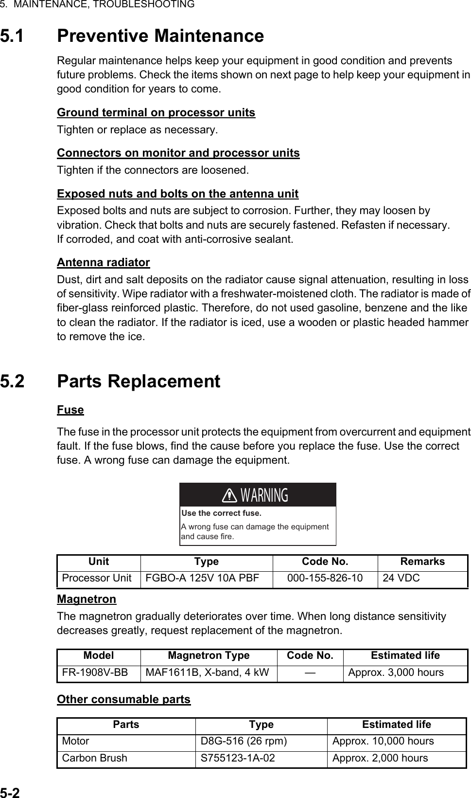
![5. MAINTENANCE, TROUBLESHOOTING5-35.3 Diagnostic Test5.3.1 Self TestThe diagnostic test checks the system for correct operation. This test is for use by ser-vice technicians, but the user can do this test to provide the service technician with information.1. Open [MAIN MENU], click [CONFIGURATION].2. Click [TEST].3. Click [SELF TEST]. Test results of mother board, control unit and processor unit are displayed. Items 5 to 10 are displayed [OK] if normal and [NG] if abnormal. When [NG] is displayed, request a service.4. To close the window, click the close button (×).5. Click outside the menu window to close the menu.5.3.2 NMEA sentences checksYou can check the sentences read into the equipment.1. Open [MAIN MENU], click [CONFIGURATION].2. Click [TEST].3. Click [SENTENCE MONITOR].4. Click the item to display. Each item refers to the external equipment connection port in the processor unit.5. To close the window, click the close button (×).6. Click outside the menu window to close the menu.*: [RIVER] mode only**: [SEA] mode only [MAIN MENU]1 BACK2 [ECHO]3 [DISPLAY]4 [MARK]6 [RADAR MAP]*7 [NAV DATA]8 [FILES]9 [CAPTURE]10 [CONFIGURATION]11 [ALARM]12 [TT•AIS]** [CONFIGURATION]1 BACK2 [OPERATION]3 [FUNCTION KEY]4 [TEST] [TEST]1 BACK2 SELF TEST3 [SENTENCE MONITOR] [SENTENCE MONITOR]1 BACK2 NMEA13 NMEA24 NMEA35 NMEA46 NMEA57 NMEA6](https://usermanual.wiki/Furuno-USA/9ZWRTR102.Users-Manual-5/User-Guide-3763532-Page-15.png)
![5. MAINTENANCE, TROUBLESHOOTING5-45.4 Easy TroubleshootingThis section provides troubleshooting procedures that the user may follow to restore normal operation. If you cannot restore normal operation, do not attempt to check inside any unit. Leave any repair work to a qualified technician.Easy troubleshootingProblem RemedyYou can not turn on the power. • Check for blown fuse.• Check that the power connector is fastened.• Check for corrosion on the power cable connector.• Check for damaged power cable.• Check the input source for monitor.There is no response when a key is pressed.Long press the POWER key for approx. seven seconds to turn off the power. Then, turn on the power again.Key beep inaudible Adjust key beep level on the [OPERATION] menu, referring to paragraph 1.37.4.Picture not updated or picture freeze.Long press the POWER key for approx. seven seconds to turn off the power. Then, turn on the power again.The power is on and you operated the STBY/TX key to transmit. The marks and characters appear, but no echo appears.• Check that the antenna cable is fastened.• Adjust the GAIN and STC levels.• Adjust the echo brilliance.Tuning is correctly adjusted, but sensitivity is poor.• Clean the radiator face.• Replace the magnetron. Contact your dealer.There are unwanted echo around own ship.Adjust the STC level.• The icons are automatically hidden.• You can not find the icon.Turn [HIDDEN ICON] to [OFF]. See paragraph 1.36.2.You can not adjust the brilliance of the screen.Turn [EXT BRILL CTRL] to [ON] on the monitor MU-190RH. You can not set the orientation mode.• Check the connected equipment.• Check the heading input (Sentence monitor, Input port, Baud rate).• The AIS symbols are not shown.• The true trails are not shown.• The radar map is not shown.Check the connected equipment.Range rings are not shown. Adjust their brilliance with [FIXED RING]. See paragraph 1.6.3.](https://usermanual.wiki/Furuno-USA/9ZWRTR102.Users-Manual-5/User-Guide-3763532-Page-16.png)
![5. MAINTENANCE, TROUBLESHOOTING5-55.5 Advanced TroubleshootingThis section describes how to cure hardware and software troubles that should be carried out by qualified service personnel.Advanced troubleshootingProblem Probable causes or check points RemedyYou cannot turn on the power.• Blown fuse.• Mains voltage/polarity• Power supply board• Replace blown fuse.• Correct wiring and input voltage.• Replace power supply board.Power turned on but radar does not operate at all.Panel board Replace panel board.Antenna not rotating • Antenna switch setting (See the Installation manual.)• Check for the voltage for motor.• Antenna switch of antenna unit• Gear mechanism• RF_TB board• Check the setting of antenna switch.• Replace PSU board.• Check if antenna switch is ON.• Replace the motor.• Replace RF_TB board.Set [GAIN] to maximum with [STC] and [RAIN] settings at minimum. Marks and indications appear but no noise or echo.• IF amplifier• Signal cable between antenna and processor unit• VIDEO_AMP board• SPU cable connection on the VIDEO_AMP board• Replace IF amplifier.• Check continuity and isolation of coaxial cable.• Replace video amplifier.Marks, indications and noise appear but no echo in short range.• Magnetron• Modulator board• SPU board• Check magnetron current.• Replace modulator board.• Replace SPU board.Picture not updated or picture freeze-up.• Bearing signal generator• SPU board• Check that signal cables are fastened.• Replace SPU board.• Turn off and on the radar.GAIN is poor. Tuning Do the [TUNE INITIALIZE] setting. See paragraph 1.8.4.Radar is correctly tuned but sensitivity is poor.• Deteriorated magnetron• Dirt on radiator face• Check the magnetron current with the radar transmitting on 48 nm range.• Clean radiator.](https://usermanual.wiki/Furuno-USA/9ZWRTR102.Users-Manual-5/User-Guide-3763532-Page-17.png)

![AP-2APPENDIX 2 MENU TREEMAIN MENU6 RADAR MAP***4 MARK3 DISPLAY2 ECHO1 BACK*1 BACK2 TUNE INITIALIZE3 STC PRESET (OFF, ON)4 FTC PRESET (OFF, ON)1 BACK2 OWN SHIP MARK (MIN, RECTANGLE, PENTAGON)3 STERN MARK (OFF, ON)4 EBL OFFSET BASE* (STAB GND, STAB HDG, STAB NORTH)5 VRM SYNC OFFSET EBL* (OFF, ON)1 BACK2 TRANSPARENCY (OFF, ON)3 DOCKING MODE (OFF, ON)4 OWN SHIP MARK (OFF, ON)5 MENU6 HIDDEN ICON7 MARK/LINE*** (OFF, ON)8 BARGE*** (OFF, ON)9 ECHO AREA* (CIRCLE, WIDE)1 BACK2 AUTO-CLOSING* (OFF, ON)3 AUTO-CLOSING TIME* (5sec, 10sec, 20sec)1 BACK2 AUTO-HIDDEN (OFF, ON)3 AUTO-HIDEN TIME(5sec, 10sec, 20sec)4 RANGE (OFF, ON)5 MODE (OFF, ON)6 NAV DATA (OFF, ON)7 MARK (OFF, ON)8 BRILL/COLOR (OFF, ON)9 TT/AIS (OFF, ON)10 ECHO (OFF, ON)11 GAIN/STC/RAIN (OFF, ON)12 EBL/VRM (OFF, ON)13 DOCKING (OFF, ON)MAIN MENU(TO NEXT PAGE) *: [SEA] mode only ***: [RIVER] mode only1 BACK2 MAP ALIGN (OFF, ON)3 MARK/LINE INFO4 DATA DELETE1 BACK2 MARK/LINE INFO (CURRENT NUMBER, TOTAL CAPACITY: 5000)1 BACK2 MARK/LINE DELETE3 BARGE DELETE1 BACK2 SHAPE DELETE3 COLOR DELETE4 MARK/LINE ALL DELETE (NO, YES)1 BACK2 SHAPE (Select one)3 DELETE (NO, YES)1 BACK2 COLOR(GRN, BLU, YEL, CYA, MAG, WHT)3 DELETE (NO, YES)1 BACK2 COLOR (GRN, BLU, YEL, CYA, MAG, WHT)3 BARGE ALL DELETE (NO, YES)](https://usermanual.wiki/Furuno-USA/9ZWRTR102.Users-Manual-5/User-Guide-3763532-Page-20.png)
![APPENDIX 2 MENU TREEAP-37 NAV DATA8 FILES9 CAPTURE(FROM PREVIOUS PAGE)1 BACK2 PREDICTION3 DEPTH4 WIND5 ROT SCALE (30deg, 90deg, 300deg)6 RUDDER SCALE (30deg, 90deg, 120deg, 180deg)1 BACK2 OWN SHIP POSITION (DUAL-GPS, SC)1 BACK2 GRAPH TYPE(NUMERICAL, GRAPHICAL)3 DUAL SENSOR (BOTH, FRONT, AFT)4 DEPTH SCALE5 TIME SCALE (15sec, 30sec, 1min, 3min)6 DEPTH ALARM VALUE (0.00 - 9.99 m, 5.00)1 BACK2 SCALE TYPE(RIVER, SEA)3 RIVER (4, 10, 40)4 SEA(10, 20, 50, 100, 200, 500)1 BACK2 WIND DIRECTION (OFF, COME FROM, GO TO)(TO NEXT PAGE)1 BACK2 DRIVE SELECT (SD-1, SD-2)3 DRIVE INFO4 SAVE DATA5 REPLAY (READ) DATA6 DELETE DATA7 REMOVE EXTERNAL MEDIA (SD-1, SD-2)1 BACK2 DRIVE INFO (USED, AVAILABLE)1 BACK2 MARK/LINE*** (1 BACK, 2 NAME)3 SETTING DATA (1 BACK, 2 NAME)4 INSTALL DATA**5 ALARM HISTORY (1 BACK, 2 NAME)6 LOG FILE (1 BACK, 2 NAME)1 BACK2 MARK/LINE*** (1 BACK, 2 NAME)3 SETTING DATA (1 BACK, 2 NAME)4 INSTALL DATA**1 BACK2 MARK/LINE*** (1 BACK, 2 NAME)3 SETTING DATA (1 BACK, 2 NAME)4 INSTALL DATA**5 ALARM HISTORY (1 BACK, 2 NAME)6 LOG FILE (1 BACK, 2 NAME)**: For service menu1 BACK2 DRIVE SELECT (SD-1, SD-2)3 DRIVE INFO4 AUTO CAPTURE5 DELETE CAPTURE DATA6 REMOVE EXTERNAL MEDIA (SD-1, SD-2)1 BACK2 DRIVE INFO (THE NUMBER OF FILES, USED, AVAILABLE)1 BACK2 AUTO CAPTURE (OFF, ON)3 INTERVAL (1 to 999 min, 1)1 BACK2 MANUAL DATA (1 BACK(LONG=TOP), 2 DELETE)3 AUTO(FAST) DATA (1 BACK(LONG=TOP), 2 DELETE)4 AUTO(NORMAL) DATA (1 BACK(LONG=TOP), 2 DELETE) *: [SEA] mode only ***: [RIVER] mode only(available in stand-by mode only)(available in stand-by mode only)](https://usermanual.wiki/Furuno-USA/9ZWRTR102.Users-Manual-5/User-Guide-3763532-Page-21.png)
![APPENDIX 2 MENU TREEAP-410 CONFIGURATION(FROM PREVIOUS PAGE)1 BACK2 OPERATION3 FUNCTION KEY1 BACK2 REF POINT (ANT, CCRP)3 KEY BEEP (OFF, LOW, MID, HIGH)4 OWN SHIP VECTOR (OFF, COURSE, HDG)5 CURSOR SIZE (SMALL, LARGE)6 GUIDANCE (OFF, ON)7 TOUCH PAD8 POINTING-DEVICE1 BACK2 TOUCH-PAD (OFF, ON)3 SENSITIVITY (1, 2, 3, 4, 5) 1 BACK2 POINTING-DEVICE(OFF, ON)3 SENSITIVITY (1, 2, 3, 4, 5)1 BACK2 F13 F2 (Same as [F1], Default: [DOCKING])1 BACK2 ECHO3 STD KEY4 TT•AIS5 OPERATION6 BRILL7 CUSTOM1 BACK2 CUSTOM-MENU, FTC, IR, ES, EAV, AUTO-GAIN, AUTO-STC, AUTO-RAIN, TUNE SELECT, TRAIL DISPLAY, TRAIL TIME, TRAIL T/R, WIPER1 BACK2 ALARM ACK, EBL OFFSET, OPERATION MODE, ORIENTATION-MODE, CU-TM RESET*, VECTOR TIME, VECTOR MODE, TT-LIST*, AIS-LIST, BRILL-MENU, MARK***, CAPTURE1 BACK2 TT-DISP*, AIS-DISP, PAST POSN INTERVAL, REF MARK*, CPA LIMIT, CPA, TCPA, AZ1*, AZ2*, AIS SCALED SYMBOL1 BACK2 ECHO COLOR, MONITOR BRILL, PANEL DIMMER, TRANSPARENCY, ALARM1*, ALARM2*, ECHO AREA*, DOCKING, MARK/LINE-ON***, BARGE-ON***, MAP ALIGN***, MARK/LINE ALL DELETE***, BARGE ALL DELETE***1 BACK2 USER NAME 1 (BRL1-1 - BRL1-4)3 USER NAME 2 (BRL2-1 - BRL2-4)4 USER NAME 3 (BRL3-1 - BRL3-4)5 USER NAME 4 (BRL4-1 - BRL4-4)1 BACK2 USER NAME 1 (CUSTOM1-1 - CUSTOM1-4)3 USER NAME 2 (CUSTOM2-1 - CUSTOM2-4)4 USER NAME 3 (CUSTOM3-1 - CUSTOM3-4)5 USER NAME 4 (CUSTOM4-1 - CUSTOM4-4)(TO NEXT PAGE) *: [SEA] mode only ***: [RIVER] mode only](https://usermanual.wiki/Furuno-USA/9ZWRTR102.Users-Manual-5/User-Guide-3763532-Page-22.png)
![APPENDIX 2 MENU TREEAP-511 ALARM12 TT•AIS(FROM PREVIOUS PAGE)1 BACK2 TT•AIS3 TARGET ALARM*1 BACK2 ALR1 MODE (IN, OUT)3 ALR2 MODE (IN, OUT)4 LEVEL (1, 2, 3, 4)1 BACK2 CPA LIMIT (OFF, ON)3 RANGE (0.1 - 24 NM, 1 NM)4 TIME (30sec, 1-15min, 1min)1 BACK2 CPA LIMIT1 BACK2 NMEA13 NMEA24 NMEA35 NMEA46 NMEA57 NMEA61 BACK2 SELF TEST3 SENTENCE MONITOR1 BACK2 VECTOR3 PAST POSN4 SYMBOL5 ACUQIRE ZONE*1 BACK2 VECTOR MODE(Ground-Stab: VECTOR REL, VECTOR T-G Sea-Stab: VECTOR REL, VECTOR T-S3 VECTOR TIME (30sec, 1 - 6min, 1min)1 BACK2 AZ STAB (STAB NORTH, STAB HEADING)3 POLYGON STAB (OFF, STAB GND, STAB NORTH, STAB HEADING)1 BACK2 AIS3 TT* 1 BACK2 SYMBOL COLOR (GRN, BLU, CYA, MAG, WHT)1 BACK2 SYMBOL COLOR (GRN, BLU, CYA, MAG, WHT)3 ROT TAG LIMIT (000.1 - 720.0 deg/min, 000.1 deg/min)4 SCALED SYMBOL (OFF, ON)1 BACK2 INTERVAL (OFF, 0.5 min, 1 min, 2 min, 3 min, 6 min)3 POINTS (5, 10) *: [SEA] mode only4 TEST(Protected as [SERVICE MENU] in [RIVER] mode)(Protected as [SERVICE MENU] in [RIVER] mode)](https://usermanual.wiki/Furuno-USA/9ZWRTR102.Users-Manual-5/User-Guide-3763532-Page-23.png)