Furuno USA 9ZWRTR102 Transceiver for Radar User Manual OME 36700 A
Furuno USA Inc Transceiver for Radar OME 36700 A
UserManual.wiki
>
Furuno USA
>
9ZWRTR102 User Manual
>
Users Manual 2
Contents
1.
Users Manual 1
2.
Users Manual 2
3.
Users Manual 3
4.
Users Manual 4
5.
Users Manual 5
Users Manual 2
Navigation menu
Upload a User Manual
Namespaces
Wiki Guide
HTML
PDF
Info
Views
User Manual
Discussion / Help
Navigation
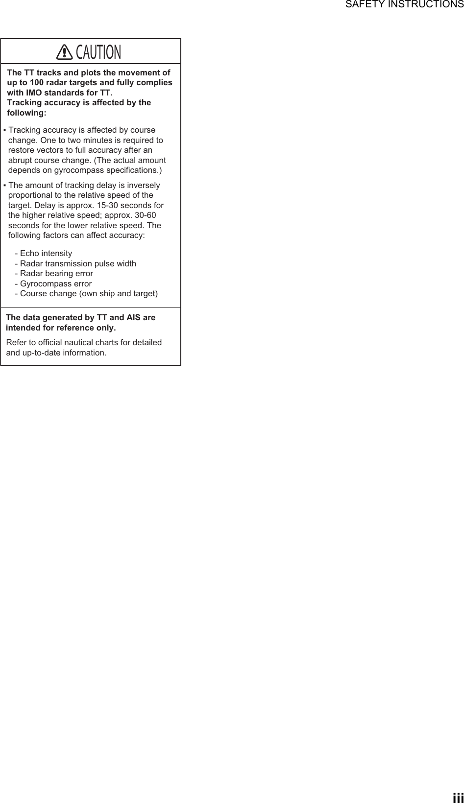
![ivTABLE OF CONTENTSFOREWORD .................................................................................................................viiiSYSTEM CONFIGURATION ..........................................................................................ix1. OPERATION ..........................................................................................................1-11.1 Controls...................................................................................................................... 1-11.2 How to Turn the Radar On/Off ................................................................................... 1-11.3 How to Transmit ......................................................................................................... 1-21.4 Radar Display Indications .......................................................................................... 1-21.5 Menu Operation ......................................................................................................... 1-41.5.1 How to operate the radar from the icons........................................................ 1-41.5.2 Menu window ................................................................................................. 1-51.5.3 How to show the hidden icons ....................................................................... 1-51.5.4 List windows................................................................................................... 1-61.6 How to Adjust Display Brilliance, Panel Dimmer ....................................................... 1-61.6.1 Display brilliance ............................................................................................ 1-61.6.2 Panel dimmer................................................................................................. 1-71.6.3 Brilliance Sets ................................................................................................ 1-71.7 Color Scheme ............................................................................................................ 1-91.8 Tuning ......................................................................................................................1-111.8.1 How to select the tuning method.................................................................. 1-111.8.2 Automatic tuning .......................................................................................... 1-111.8.3 Manual tuning............................................................................................... 1-111.8.4 How to initialize tuning ................................................................................. 1-111.9 Echo Area ................................................................................................................ 1-121.10 Operation Modes...................................................................................................... 1-121.10.1 How to select an operation mode................................................................. 1-121.10.2 Orientation mode.......................................................................................... 1-131.10.3 How to select an orientation mode............................................................... 1-141.10.4 How to change orientation mode presets..................................................... 1-151.11 How to Select the Range Scale ............................................................................... 1-151.12 Pulse width............................................................................................................... 1-171.12.1 How to change a pulse width ....................................................................... 1-171.12.2 How to select a pulse width.......................................................................... 1-181.13 How to Adjust the Gain (sensitivity) ......................................................................... 1-181.14 How to Reduce the Sea Clutter................................................................................ 1-191.15 How to Reduce the Rain Clutter............................................................................... 1-201.16 Cursor ......................................................................................................................1-201.17 FTC (Fast Time Constant) ....................................................................................... 1-211.18 How to Measure the Range to a Target (VRM)........................................................ 1-211.19 How to Measure the Bearing to a Target (EBL) ....................................................... 1-221.20 Offset EBL................................................................................................................ 1-231.20.1 How to measure the range and bearing between two targets...................... 1-231.20.2 Collision assessment by offset EBL............................................................. 1-251.20.3 Point of reference for origin point of offset EBL ........................................... 1-261.21 How to Off-center the Display .................................................................................. 1-271.22 Interference Rejecter................................................................................................ 1-281.23 Echo Stretch............................................................................................................. 1-281.24 Echo Averaging........................................................................................................ 1-291.25 Target Trails ............................................................................................................. 1-291.25.1 How to start, stop the trails........................................................................... 1-291.25.2 [TRAIL] menu............................................................................................... 1-301.25.3 Trail mode .................................................................................................... 1-30](https://usermanual.wiki/Furuno-USA/9ZWRTR102.Users-Manual-2/User-Guide-3763515-Page-6.png)
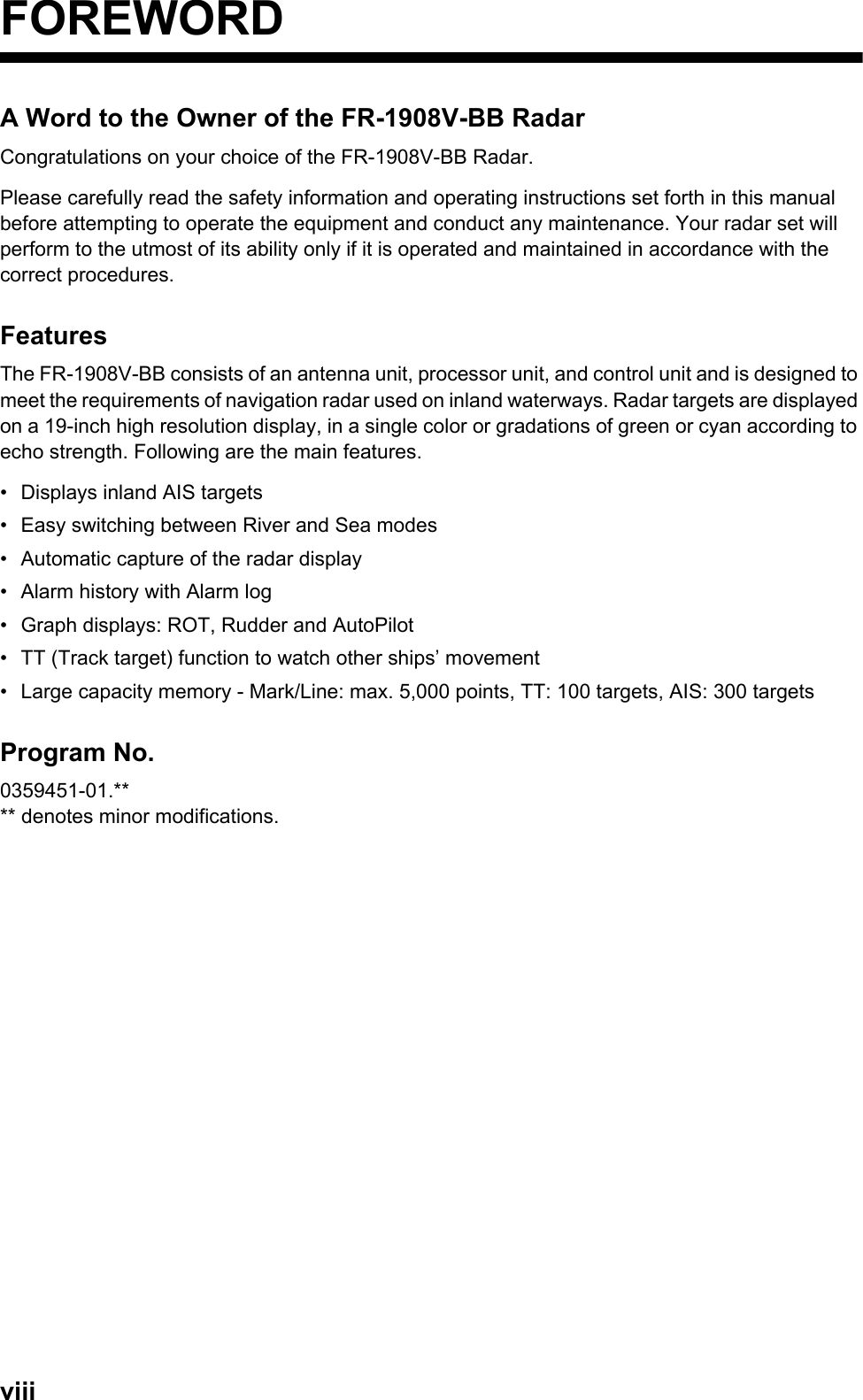
![TABLE OF CONTENTSv1.25.4 Trail level ......................................................................................................1-311.25.5 Trail time.......................................................................................................1-311.25.6 Own ship trail................................................................................................1-311.25.7 Trail color modes..........................................................................................1-321.26 Target Alarm.............................................................................................................1-321.26.1 How to set a target alarm .............................................................................1-321.26.2 How to select the alarm type ........................................................................1-331.26.3 How to select the target strength which triggers a target alarm ...................1-341.26.4 How to acknowledge the target alarm ..........................................................1-341.26.5 How to sleep a target alarm temporarily.......................................................1-341.26.6 How to delete a target alarm ........................................................................1-341.27 Nav Lines..................................................................................................................1-351.28 Alarms, Error Messages...........................................................................................1-361.28.1 Alarm indication............................................................................................1-361.28.2 Alarm description..........................................................................................1-371.28.3 Alarm summary ............................................................................................1-381.28.4 Alarm list/history ...........................................................................................1-381.28.5 Depth alarm..................................................................................................1-391.28.6 ROT alarm....................................................................................................1-391.29 Docking Mode...........................................................................................................1-391.29.1 How to activate the docking mode ...............................................................1-401.29.2 How to show or hide the docking information display ..................................1-401.29.3 Wind speed and direction.............................................................................1-401.29.4 Depth data....................................................................................................1-411.29.5 Depth graph..................................................................................................1-421.29.6 Speed and movement indications ................................................................1-421.30 How to Predict Own Ship’s Position .........................................................................1-431.31 How to Program Function Keys (F1 and F2)............................................................1-441.32 Markers.....................................................................................................................1-461.32.1 [MARK] menu ...............................................................................................1-461.32.2 Heading line .................................................................................................1-461.32.3 Stern mark....................................................................................................1-471.32.4 North mark....................................................................................................1-471.32.5 Own ship mark .............................................................................................1-471.32.6 Barge mark...................................................................................................1-481.33 NAV Data..................................................................................................................1-511.33.1 How to show ship’s position or speed and depth alternately........................1-511.33.2 How to show wind data or date alternately...................................................1-531.33.3 Time to the cursor position ...........................................................................1-541.33.4 Cursor position .............................................................................................1-541.33.5 ROT, Rudder and Autopilots Graphs ...........................................................1-541.34 Customized Menus...................................................................................................1-551.35 SD Cards..................................................................................................................1-571.35.1 About the SD cards ......................................................................................1-571.35.2 How to save and replay the data..................................................................1-581.36 How to Set Menu and Icon Behavior........................................................................1-591.36.1 Auto closing of menu window.......................................................................1-591.36.2 Icons.............................................................................................................1-601.37 Other Features .........................................................................................................1-611.37.1 Guidance box (Help function).......................................................................1-611.37.2 Menu transparency.......................................................................................1-611.37.3 Display capture.............................................................................................1-621.37.4 How to customize the operation ...................................................................1-641.37.5 Transmit time................................................................................................1-65](https://usermanual.wiki/Furuno-USA/9ZWRTR102.Users-Manual-2/User-Guide-3763515-Page-7.png)
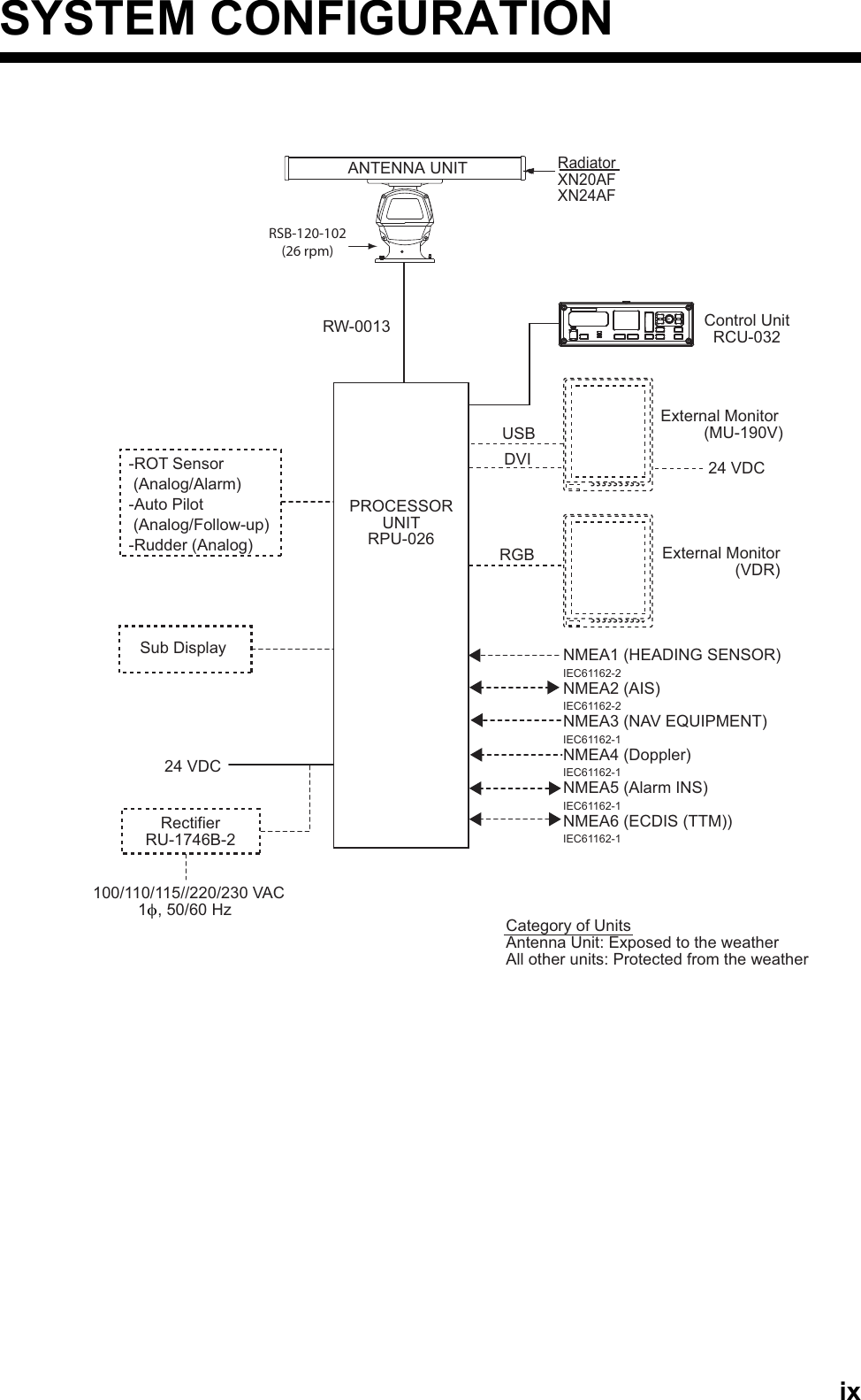
![TABLE OF CONTENTSvi2. TARGET TRACKING (TT) .....................................................................................2-12.1 TT Display On/Off ...................................................................................................... 2-12.2 How to Acquire and Track Targets............................................................................. 2-32.3 Manual Acquisition ..................................................................................................... 2-32.4 Automatic Acquisition................................................................................................. 2-42.4.1 How to set an acquisition zone ...................................................................... 2-42.4.2 How to sleep an acquisition zone................................................................... 2-42.4.3 How to delete an acquisition zone ................................................................. 2-42.4.4 Acquisition zone reference.............................................................................2-52.5 How to Stop Tracking a Target .................................................................................. 2-52.6 TT Symbol Attributes.................................................................................................. 2-62.6.1 TT symbol brilliance ....................................................................................... 2-62.6.2 TT symbol color.............................................................................................. 2-62.7 Lost Target .................................................................................................................2-72.7.1 Lost target filter .............................................................................................. 2-72.7.2 How to acknowledge a lost target .................................................................. 2-72.8 TT Data ......................................................................................................................2-82.9 TT List ........................................................................................................................ 2-92.10 Vector Modes ...........................................................................................................2-102.10.1 Description of vectors................................................................................... 2-102.10.2 Vector mode and length............................................................................... 2-102.11 Past Position Display ............................................................................................... 2-112.11.1 How to select the dot number and interval of the past position.................... 2-112.11.2 Past position display mode .......................................................................... 2-112.12 CPA/TCPA Alarm..................................................................................................... 2-123. AIS OPERATION ...................................................................................................3-13.1 AIS Display On/Off ..................................................................................................... 3-13.2 AIS Display Filter........................................................................................................ 3-33.3 How to Activate Targets ............................................................................................. 3-43.3.1 How to activate specific targets manually ...................................................... 3-43.3.2 How to activate all targets.............................................................................. 3-43.4 How to Sleep Targets................................................................................................. 3-53.4.1 How to sleep an individual target ................................................................... 3-53.4.2 How to sleep all targets.................................................................................. 3-53.5 AIS Symbol Attributes ................................................................................................ 3-53.5.1 AIS symbol brilliance...................................................................................... 3-53.5.2 AIS symbol size and color.............................................................................. 3-53.6 Past Position Display ................................................................................................. 3-63.6.1 How to select the number and interval of the past position............................ 3-63.7 Lost Target .................................................................................................................3-73.7.1 Lost target filter .............................................................................................. 3-73.7.2 How to acknowledge a lost target .................................................................. 3-73.8 ROT Setting ............................................................................................................... 3-83.9 CPA/TCPA Alarm....................................................................................................... 3-83.10 Automatic Target Activation ....................................................................................... 3-93.11 AIS Target Data ....................................................................................................... 3-103.12 AIS List..................................................................................................................... 3-114. RADAR MAP..........................................................................................................4-14.1 What is a Radar Map? ............................................................................................... 4-14.2 [MARK] icon ............................................................................................................... 4-14.3 How to Enter Marks, Lines ......................................................................................... 4-24.3.1 How to enter a mark, line with at the cursor position ..................................... 4-24.3.2 How to enter a mark by latitude and longitude position input......................... 4-34.3.3 How to enter a mark at current position ......................................................... 4-3](https://usermanual.wiki/Furuno-USA/9ZWRTR102.Users-Manual-2/User-Guide-3763515-Page-8.png)


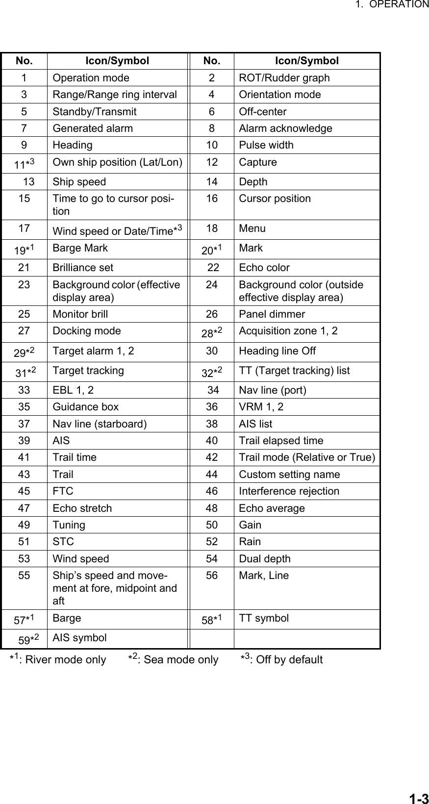
![1-11. OPERATION1.1 Controls1.2 How to Turn the Radar On/Off1. Open the cover at the bottom left section on the control unit. Press the Power key to turn the radar on.2. Press the Power key on the control unit to turn off the power.Control FunctionPower key Turn On/Off power. Power lamp lights when the power is turned on.STBY/TX Switch between stand-by and transmission.Touch pad Move the selection or the cursor.Left-clickRight-clickRANGE Select display range.Select the pulse width.EBL Display/Hide EBL (Electronic bearing line).VRM Display/Hide VRM (Variable range marker).MENU Display/Hide Menu window.BRILL Move the cursor on the [BRL] (brill) icon.OFF CENTER Off-center own ship position.HL OFF Hide the heading line temporarily.F1, F2 Execute menu short cut assigned.Setting knob Operate EBL, VRM, Brilliance.Select the menu item.PUSH TO SELECTEBLMENUVRMBRILLF1F2OFFCENTERHLOFFRANGESTBYTXADJUSTPower keyPower lamp Touch pad Setting knobLeft button Right button](https://usermanual.wiki/Furuno-USA/9ZWRTR102.Users-Manual-2/User-Guide-3763515-Page-13.png)
![1. OPERATION1-21.3 How to TransmitTo transmit, press the STBY/TX key while [STBY] is displayed. Radar echoes are displayed on the screen with the previously used settings of range.Each press of the STBY/TX key switches between stand-by and transmit (You can also switch between stand-by and transmission by clicking the [STBY/TX] indication.). The antenna is stopped in stand-by, and rotates in transmission. The magnetron in the antenna unit generates the radar pulses and decays over time. To extend the life of the magnetron, keep the radar in stand-by when its use is not required.1.4 Radar Display IndicationsThe illustration below shows all the icons and symbols (both in the [RIVER] and [SEA] modes) that may appear on the display. Some icons or symbols may not be shown depending on the display mode.Radar display example10.4m/sFront 10.4mAft 13.7m4.8kn4.8kn4.8knSEA ROTRUDDER8 /2 kmHEAD- UP ►STBY ►OFFCENT OFFHDG 123.4°ALARM ►ALARMACKM1MENUBARGE ON2WHT ►MARK ONCYA ►DOCK ONBRL2-3 ►ECHOAZ1 ►AZ2 ►ALR1 ►ALR2 ►HL OFFTTON►LISTEBL1 123.4°>EBL2 82.9°NAV 0.160TTNMAISFIL►TUNEVRM1 1.567VRM2 0.160NAV 0.160NMLIST ►NMNMMANMANMANAUTOGAINSTCRAIN7540FTC 1IR 1ES 2EAV 3TRAIL ►2.50sec00m03sRELONCUSTOM3-4 ►OS POSN N 34° 40.0000′E 135° 20.0000′UTCCAPT±300 º/m±180 ºAUTOSPD BT GPS-F ►DPT AFT ►CURSOR TTG6.34km / 300.3°TWIND6.7 kn/h123.4 m02m45s10.4 m/s20-SEP-201223:59GUIDANCE BOXGUIDANCE BOX12357648910111213141516171918222124262532293334362728233130 374140384239444853525149504754565758593543454655GRNB-IN BLKOUT D-GRNMONIPANL5015Own ship20Cursor*317](https://usermanual.wiki/Furuno-USA/9ZWRTR102.Users-Manual-2/User-Guide-3763515-Page-14.png)
![1. OPERATION1-41.5 Menu Operation1.5.1 How to operate the radar from the iconsHow to select the menu icon on the screenUse the touch pad to select an icon. The icon is highlighted when correctly selected.Operations available with the left button• Open the main menu when the [MENU] icon is selected (see paragraph 1.5.2).• Select options related to the selected icon cyclically.Operations available with the right buttonOpens the sub menu window for the menu icon with the option mark (triangle).Operation available with the setting knob• Rotation: Change the setting value on the setting box (clockwise to decrease the value, counterclockwise to increase the value).• Press: Move the cursor on the setting box respectively among [GAIN], [STC] and [RAIN].How to select the menu items on the menu window1. Use the touch pad to select the menu item. The selected menu item is enclosed with a rectangle.2. Use the touch pad to select an option. The selected option is enclosed with a rectangle.Click outside the menu window to close the menu window.Put the cursor on an iconHighlightedHEAD-UP ► HEAD-UP ►HEAD-UP ►HEAD-UP ►Right-clickSelected menuSub menuECHOB-INOUTAZ1 AZ2 ALR1 ALR2GRNBLKD GRNBRL 2-3 ►BRL 2-3 ►Option markBRL 2-3 ►BRL 2-3 ► [BRILL MENU]1 BACK2 [EDIT]3 [PRESET]Menu options [TRAIL]1 BACK2 TRAIL MODE REL /TRUE3 TRAIL LEVEL 1 /2/3/44 OS TRAIL OFF/1/25 TRAIL COLOR OPTION DEFAULT/USERClick [TRAIL]1 BACK2 TRAIL MODE REL /TRUE3 TRAIL LEVEL 1 /2/3/44 OS TRAIL OFF/1/25 TRAIL COLOR OPTION DEFAULT/USERMenu items](https://usermanual.wiki/Furuno-USA/9ZWRTR102.Users-Manual-2/User-Guide-3763515-Page-16.png)
![1. OPERATION1-5Mouse operationA mouse can be connected to the processor unit to control radar functions. The table below compares operation with the control unit and mouse.Note: Connect the USB mouse to the processor unit directly. Do not use a USB hub when connecting the USB mouse to the prosessor unit.1.5.2 Menu windowMain menuTo open the main menu, put the cursor on the [MENU] icon.Note: Hereafter, placement of the cursor and operation of the left button are omitted in procedures done with icons. For example, the above sentence would be written as "Click the [MENU] icon."To close the main menu, left-click or right-click outside the menu window. Also, if no operation for specified duration*, the main menu is closed automatically.*: Sets the duration on the [AUTO-CLOSING TIME] menu.1.5.3 How to show the hidden iconsIf the radar can be set to hide some icons after a specified interval, click the [MENU] icon to display the hidden icons.Control unit MouseCursor movement by touch pad Cursor movement by mouse operationLeft button press Left-clickRight button press Right-clickSetting knob rotation • Wheel rotation• Cursor movement when selecting menusSetting knob press Wheel pressClick[MAIN MENU] for [RIVER] modeBARGE ON2WHTONCYA DOCK OFFBRL2-3ECHOB-INOUTMONIPANLHL OFFEBL1 123.4°>EBL2 82.9°NAV 0.160TTkmGRNBLKD-GRN5015MARKMARKMENUMENU [MAIN MENU]1 BACK2 [ECHO]3 [DISPLAY]4 [MARK]6 [RADAR MAP]7 [NAV DATA]8 [FILES]9 [CAPTURE]10 [CONFIGURATION] (at the bottom left corner on the screen in [RIVER] mode )ClickHidden icons appear.BARGE ON2WHTONCYA DOCK OFFBRL2-3ECHOB-INOUTMONIPANLHL OFFEBL1 123.4°>EBL2 82.9°NAV 0.160TTkmGRNBLKD-GRN5015MARKMARKMENUMENUMENUMENU](https://usermanual.wiki/Furuno-USA/9ZWRTR102.Users-Manual-2/User-Guide-3763515-Page-17.png)
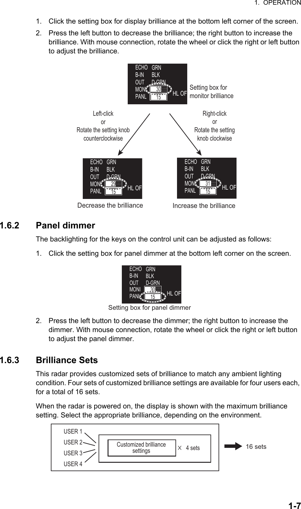
![1. OPERATION1-61.5.4 List windowsThere are three list windows (TT, AIS and Alarm) and they provide information about tracking targets, AIS targets and generated alarms.• TT list: Click the [LIST] icon for TT at the bottom of the display to show the TT list.• AIS list: Click the [LIST] icon for AIS at the bottom of the display to show the AIS list.• Alarm list: Right-click the [ALARM] icon at the top left corner then click [3 ALARM LIST/HISTORY] to show the Alarm list.How to close a list windowClick the close button (×) at the top right corner of the list window. Alternately, right-click or left-click outside the window.1.6 How to Adjust Display Brilliance, Panel Dimmer 1.6.1 Display brillianceYou can adjust the display brilliance (setting range: 0 to 50) with the [MONI] icon. The connection between the processor unit and the monitor unit MU-190RH with the USB cable (supplied) is required. See the Operator’s manual of MU-190RH.Note: This function is available when the following menus of MU-190RH are set as below:• [AUTO DIMMER]: [OFF] • [EXT BRILL CTRL]: [ON][TT LIST]No. RANGE BEARING CPA TCPA001 9. 60NM 058. 8°T 0. 00NM 00m00s002 19. 2NM 059. 0°T 0. 00NM 00m00s[AIS LIST] <SORT>NAME-UP 1/1MMSI NAME12XXXXXXXXX ABCXX2345XXXXXXX AXX[ALARM LIST] 1/1ITEM TYPE DATE/TIMEROT SENSOR ERROR 00:00:000000/00/00AIS RECEIVE ERROR AIS WARNING 00:00:000000/00/00](https://usermanual.wiki/Furuno-USA/9ZWRTR102.Users-Manual-2/User-Guide-3763515-Page-18.png)
![1. OPERATION1-8How to select a customized brilliance set1. Click the [BRL] icon at the bottom left corner on the screen to show the [BRILL MENU] window.2. Click the user name and the required brilliance set.3. Click outside the menu window to close the menu.How to edit [BRILL MENU]You can edit the menu contents for each brilliance set.1. Right-click the [BRL] icon at the bottom left corner on the screen to show the [BRILL MENU] window.Note: The [BRL1-1] setting is fixed as a default setting. You can edit the setting, but when the system is turned off, the default setting is restored. To save a custom brilliance set, select a setting other than [BRL1-1].2. Click [EDIT].3. Click [USER NAME].4. To edit the name, click the name column then enter the name with the software keyboard. Click the [END] button to finish.• Change the digit: Rotate scrollwheel.• Delete a character: Use the [BS] button on the software keyboard.5. Click [USER COMMENT] to edit. The editing procedure is the same as that for [USER NAME]. Refer to step 4.6. To edit the comment, click the respective BRL column then enter the comment with the software keyboard. Click the [END] button to finish.7. Click the menu item, [4 ECHO COLOR] to [11 BRILL DETAIL], to edit.8. Set the option for each menu item as appropriate.9. Click [SAVE & QUIT] to save the settings.[BRL] icon2WHTONCYA DOECHOB-INOUTGRNBLKD-GRNMARKMARKBRL2-3BRL2-31 BACK2 USER-NAME1 BRL1-1/ BRL1-2/ BRL1-3/ BRL1-43 USER-NAME2 BRL2-1/ BRL2-2/ BRL2-3/ BRL2-44 USER-NAME3 BRL3-1/ BRL3-2/ BRL3-3/ BRL3-45 USER-NAME4 BRL4-1/ BRL4-2/ BRL4-3/ BRL4-4[BRILL MENU]Click [BRILL MENU]1 BACK2 [EDIT]3 [PRESET]Right-click[BRL] icon2 WHTONCYA DOECHOB-INOUTGRNBLKD-GRNMARKMARKBRL2-3BRL2-31 BACK2 USER NAME USER NAME 13 USER COMMENT BRL1-14 ECHO COLOR YEL/GRN/WHT/AMB/ M-GRN/M-CYA5 BACK COLOR (INSIDE) BLK/D-BLU/L-BLU/ D-GRY6 BACK COLOR (OUTSIDE) BLK/D-BLU/L-BLU/ D-GRY/D-GRN7 TRAIL COLOR YEL/GRN/WHT/AMB/BLU8 MONITOR BRILL9 PANEL DIMMER10 [COLOR DETAIL]11 [BRILL DETAIL]12 SAVE & QUIT[EDIT][END] button](https://usermanual.wiki/Furuno-USA/9ZWRTR102.Users-Manual-2/User-Guide-3763515-Page-20.png)
![1. OPERATION1-91.7 Color SchemeYou can select the color for echo and background color (inside/outside) with the display icons.Available colorsYou can set the customized color for the following items on [COLOR DETAIL].1. Right-click the [BRL] icon at the bottom left corner on the screen to show the [BRILL MENU] window.2. Click [EDIT].3. Click [COLOR DETAIL].4. Set the option for each menu item as appropriate.5. Click [SAVE & QUIT] to save the settings.Available options (Each color is selectable respectively)[ECHO COLOR] YEL(yellow)GRN(green)WHT(white)AMB(amber)M-GRN* M-CYA*[BACK COLOR(INSIDE)]BLK(black)D-BLU(dark blue)L-BLU(light blue)D-GRY (dark gray)——[BACK COLOR (OUTSIDE)]BLK(black)D-BLU(dark blue)L-BLU(light blue)D-GRY (dark gray)D-GRN(dark green)—• Echo color• Back color(effective display area)• Back color(outside effective display area)• Trail color• Character color• Fixed range ring color• Gyro scale color• EBL/VRM/NAV LINE color• Alarm indication• Cursor colorCYA DOECHOB-INOUTMONIPANLHGRNBLKD-GRN5015MARKBRL2-3BRL2-3Click the icon to change the color.1 BACK2 CHARACTER GRN/RED/WHT3 FIXED RING GRN/WHT4 GYRO RING L-BLU/RED/GRN/WHT5 EBL/VRM/NAV LINE L-BLU/GRN/WHT6 ALARM RED/WHT7 CURSOR GRN/WHT [COLOR DETAIL]](https://usermanual.wiki/Furuno-USA/9ZWRTR102.Users-Manual-2/User-Guide-3763515-Page-21.png)
![1. OPERATION1-10Default settings for [USER 1] to [USER 4]Available colors*: [M-GRN]: Multi-green (green gradation), for [SEA] mode only[M-CYA]: Multi-cyan (cyan gradation), for [SEA] mode onlyAvailable options (Each color is selectable)[USER 1] [USER 2] [USER 3] [USER 4][ECHO COLOR] GRN (green) WHT (white) GRN (green)[BACK COLOR (INSIDE)] BLK (black)[BACK COLOR (OUTSIDE)] BLK (black) D-BLU(dark blue)D-GRY(dark gray)D-GRN(dark green)[TRAIL COLOR] GRN (green) WHT (white) GRN (green)[COLOR DETAIL][CHARACTER] WHT (white)[FIXED RING] WHT (white)[GYRO RING] GRN (green) WHT (white)[EBL/VRM/NAV LINE] GRN (green)[ALARM] RED[CURSOR] GRN (green)Available options (Each color is selectable)[ECHO COLOR] YEL(yellow)GRN(green)WHT(white)AMB(amber)M-GRN*M-CYA*[BACK COLOR(INSIDE)]BLK(black)D-BLU(dark blue)L-BLU(light blue)D-GRY (dark gray)——[BACK COLOR (OUTSIDE)]BLK(black)D-BLU(dark blue)L-BLU(light blue)D-GRY (dark gray)D-GRN(dark green)—[TRAIL COLOR] YEL(yellow)GRN(green)WHT(white)AMB(amber)BLU(Blue)—[COLOR DETAIL][CHARACTER] GRN (green)RED WHT(white)———[FIXED RING] GRN (green)WHT(white)—— ——[GYRO RING] L-BLU(light blue)RED GRN (green)WHT (white)——[EBL/VRM/NAV LINE]L-BLU (light blue)GRN(green)WHT(white)———[ALARM] RED WHT(white)—— ——[CURSOR] GRN (green)WHT(white)—— ——](https://usermanual.wiki/Furuno-USA/9ZWRTR102.Users-Manual-2/User-Guide-3763515-Page-22.png)
![1. OPERATION1-111.8 Tuning1.8.1 How to select the tuning methodThe tuning method, auto tuning or manual tuning, can be selected with the tuning icon as follows.Click the tuning icon ([AUTO] or [MAN]) at the bottom right corner on the screen to switch between [AUTO] and [MAN].1.8.2 Automatic tuningClick the tuning icon to select [AUTO] referring to paragraph 1.8.1.1.8.3 Manual tuning1. Click the tuning icon to select [MAN] referring to paragraph 1.8.1.2. Put the cursor on the tuning bar.3. Rotate the setting knob to adjust the tuning. The best tuning point is where the bar swings maximum. The triangle in the bar graph shows tuning level; not the tuning condition.1.8.4 How to initialize tuningAutomatic tuning is initialized during the installation. However, if you feel that automatic tuning is not working properly try re-initializing the tuning. Open [MAIN MENU] then click [ECHO] to open [ECHO] menu. Then click [TUNE INITIALIZE] to start the initialization.The tuning bar turns yellow and moves during the initialization.Note 1: The display may appear incorrect during initialization, caused by changes in pulse or tuning levels.Note 2: The following operations cancel the initialization process.• Change of range• Go [STBY] mode• Change of pulse widthNM MANAUTOGAIN75EAV 300m03sONTUNEPut the cursor inside box to adjust tuning, when [MAN TUNE] is selected.Tuning barTuning level Tuning icon ([AUTO] or [MAN]) [ECHO]1 BACK2 TUNE INITIALIZE3 STC PRESET OFF/ON4 FTC PRESET OFF/ONAUTO TUNETuning bar (yellow)Tuning level moves during initialization](https://usermanual.wiki/Furuno-USA/9ZWRTR102.Users-Manual-2/User-Guide-3763515-Page-23.png)
![1. OPERATION1-121.9 Echo AreaThe echo display area can be selected for [CIRCLE] or [WIDE], in the [SEA] mode.1. Open [MAIN MENU], click [DISPLAY].2. Click [ECHO AREA] then select the option.[CIRCLE]: Echoes in the radar circle.[WIDE]: Echoes in the whole of the display3. Click outside the menu window to close the menu.1.10 Operation ModesThis radar has two operating modes: river mode and sea mode.• The river mode provides the radar display used at river.• The sea mode provides the traditional radar display.1.10.1 How to select an operation modeClick the operation mode icon at the top left corner of the screen to select [RIVER] or [SEA].Note 1: To enable switching of the operation mode, the [OPERATION TYPE] setting, in the [SERVICE MENU], must be set to [RIVER-SEA]. See your dealer.Note 2: To change the operation mode ([RIVER] or [SEA]), go to [STBY] once to select the operation mode then go to [TX] mode. The following items are set according to the operation mode.• Orientation mode• Range• Units• Screen size (River mode: circle* only, Sea mode: circle* and wide*)*: See section 1.9.[CIRCLE] [WIDE]Gray zone: Echo areaClick the operation mode iconSEAROTRUDDER 2/ 0.4NMHEAD-UPSTBYOFFCENT HDG SOFFRIVERRORUDDE 1.6/ 0.4kmHEAD-UPSTBYOFFCENT HDGSOFF](https://usermanual.wiki/Furuno-USA/9ZWRTR102.Users-Manual-2/User-Guide-3763515-Page-24.png)
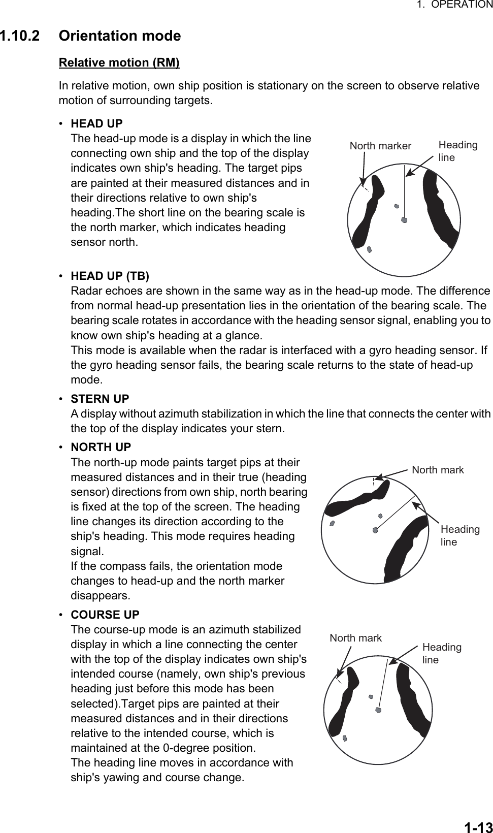
![1. OPERATION1-14True motion (TM)• NORTH UPGround (or water mass) is stabilized with compass and speed inputs. Your ship and other objects in motion move with their true courses and speed.• COURSE UPOwn ship and other moving objects move in accordance with their true courses and speed. In ground stabilized TM, all fixed targets, such as landmasses, appear as stationary echoes. In the sea stabilized TM without set and drift inputs, the landmass can move on the screen.Mode availability: The necessary data to enable the operation mode.1.10.3 How to select an orientation modeSelect the orientation mode icon then press the left button to select an orientation mode.Note: You can not set [HEAD-UP] to [OFF].Orientation modeData AvailabilityHeading L/L [RIVER] mode [SEA] modeHead up RM Yes YesHead up RM (TB) No YesStern up RM Yes YesNorth up RM No YesCourse up RM No YesNorth up TM No YesCourse up TM No YesNorth markHeading lineHEAD-UPHEAD-UPHU TB*HU TB*STERN-UPSTERN-UPNORTH-UP*NORTH-UP*CU RM*CU RM*NU TM*NU TM*CU TM*CU TM*Left-clickSwitches the orientation mode(*: Sea mode only)SEAROTRUDDER 6/ 1.5NMSTBYOFFCENT HDG LOFFHEAD-UPHEAD-UPOrientation icon(at the top left corner on the screen)](https://usermanual.wiki/Furuno-USA/9ZWRTR102.Users-Manual-2/User-Guide-3763515-Page-26.png)
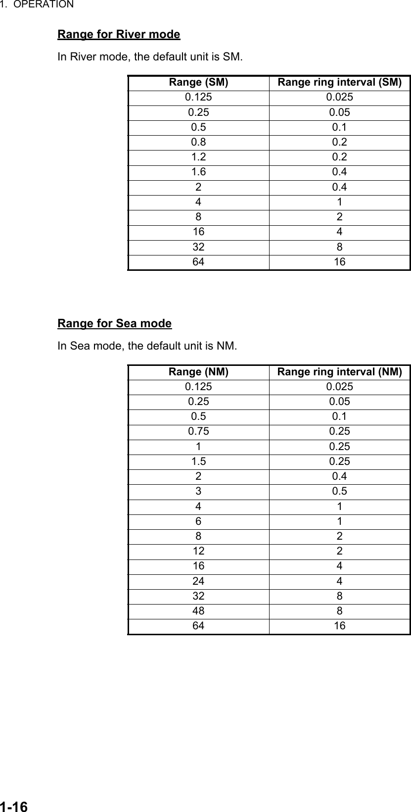
![1. OPERATION1-151.10.4 How to change orientation mode presetsSeven orientation modes are available in the [SEA] mode, two orientation modes in the [RIVER] mode. You can remove unnecessary modes from the Orientation icon as follows.1. Right-click the orientation icon to show the [ORIENTATION MODE] window.2. Click the mode to set.3. Click [ON] or [OFF]. Any mode set to [OFF] is removed from the Orientation icon.Note: You can not set [HEAD-UP] to [OFF].4. Click outside the menu window to close the menu.1.11 How to Select the Range ScaleThe selected range scale, range ring interval and pulse width are shown at the top left corner on the screen. When a target of interest comes closer, reduce the range scale so that it appears in 50-90% of the display radius.The available units for range are NM, KM, SM, and KYD. You can change the unit when installed.Left-click the range scale icon to decrease the range: right-click to increase the range.Orientation icon(at the top left corner on the screen)Right-clickSEAROTRUDDER4 /1 NMHEAD-UPSTBYOFFCENT HDG AM1OFF [ORIENTATION MODE]1 BACK2 HEAD-UP OFF/ON3 HEAD-UP TB* OFF/ON4 STERN-UP OFF/ON5 NORTH-UP* OFF/ON6 COURSE-UP* OFF/ON7 NORTH-UP TM* OFF/ON8 COURSE-UP TM* OFF/ON *: [SEA] mode only SEAROTRUDDERHEAD-UPOFFCENT HDG 123.4°ALARMALARMACKOFFRange ring intervalRange scale 6/ 1.5NM 6/ 1.5NMRight-clickRange scale selectedLeft-clickIncrease the rangeDecrease the range 0.5/ 0.1NM 0.75/ 0.25NM 1/ 0.25NM](https://usermanual.wiki/Furuno-USA/9ZWRTR102.Users-Manual-2/User-Guide-3763515-Page-27.png)
![1. OPERATION1-171.12 Pulse widthThe pulse width in use is displayed at the top left corner on the screen. The pulse widths are set to each range scale and custom setup. Use a longer pulse width when your purpose is long range detection. Use a shorter pulse width when the resolution is important.1.12.1 How to change a pulse widthThe pulse width in use is displayed at the top left corner of the screen using the indications shown in the table below.Left-click the pulse icon to shorten the pulse width or right-click to lengthen the pulse width.Appropriate pulse widths are preset to individual range scales. If you are not satisfied with the current pulse width settings, you may change them referring to paragraph 1.12.2.Pulse width for [RIVER] modePulse width for [SEA] modeRange (SM) Available pulse width0.125/ 0.25/ 0.5/ 0.8/ 1.2 S1.6/2 S/M14M1/M28/16 M2/L32/64 LRange (NM, SM) Available pulse width0.125/ 0.25/ 0.5/ 0.75/ 1 S1.5/ 2 S/M13/ 4 M1/M26/ 8/ 12/ 16 M2/L24/ 32/ 48/ 64 LRange (km, kyd) Available pulse width0.125/ 0.25/ 0.5/ 0.75/ 1/ 1.5/ 2 S3/ 4 S/M16/ 8 M1/M212/ 16/ 24/ 32 M2/L48/ 64 LSTBYOFFCENT HDG 1OFFHEAD-UPHEAD-UPM1M1Pulse iconIndication[S]: Short pulse[M1]: Medium pulse 1[M2]: Medium pulse 2[L]: Long pulse](https://usermanual.wiki/Furuno-USA/9ZWRTR102.Users-Manual-2/User-Guide-3763515-Page-29.png)
![1. OPERATION1-181.12.2 How to select a pulse width1. Right-click [CUSTOM] icon at the bottom right corner on the screen to show [CUSTOM MENU].2. Click [EDIT].3. Click [PULSE WIDTH].4. Click the range in use.5. Click the desired pulse width.6. Click outside the menu window to close the menu.1.13 How to Adjust the Gain (sensitivity)The gain functions to adjust the sensitivity of the receiver for the best reception. The gain can be adjusted automatically or manually.1. Click the gain mode icon at the bottom right corner on the screen to show [MAN] or [AUTO] as appropriate.2. For manual adjustment, rotate the setting knob to adjust the gain so that weak noise appears on all of the screen. If the gain is too low, weak echoes are erased. If the gain is too high, the background noise hides weak targets. For auto mode, the setting range is -50 to 50. For manual mode, 0 to 100.FTC 1IR 1TRAIL►CUSTOM1-1►CUSTOM1-1►Right-click [CUSTOM MENU]1 BACK2 [EDIT]3 [PRESET]1 BACK2 USER NAME USER NAME 13 USER COMMENT CUSTOM4-44 [GAIN/STC/RAIN]5 FTC OFF/1/26 INT REJECT OFF/1/2/37 ECHO STRETCH OFF/1/2/38 ECHO AVERAGE OFF/1/2/39 WIPER OFF/ON10 VIDEO CONTRAST TYPE A/B/C/D11 [STC CURVE]12 LOW LEVEL ECHO 013 TT ECHO LEVEL 1314 [PULSE WIDTH (RIVER)]15 [PULSE WIDTH (SEA)]16 SAVE ∆ QUIT#14 is shown in [RIVER] mode#15 is shown in [SEA] mode [EDIT]For [SEA] modeFor [RIVER] mode [PULSE WIDTH (SEA)]1 BACK2 PULSE 0.125/0.25/0.5/0.75-1 S3 PULSE 1.5-2 S /M14 PULSE 3-4 M1 /M25 PULSE 6/8/12-16 M2 /L6 PULSE 24/32/48-64 L [PULSE WIDTH (RIVER)]1 BACK2 PULSE 0.125/0.25/0.5/0.8-1.2 S3 PULSE 1.6-2 S /M14 PULSE 4 M1 /M25 PULSE 8-16 M2 /L6 PULSE 32-64 L [PULSE WIDTH (SEA)]1 BACK2 PULSE 0.125/0.25/0.5/0.75/1/1.5-2 S3 PULSE 3-4 S /M14 PULSE 6-8 M1 /M25 PULSE 12/16/24-32 M2 /L6 PULSE 48-64 LRange unit: NM, SM Range unit: km, kydClick[AUTO]: Auto [MAN]: ManualMAN TUNE MAN GAIN AUTO STC AUTO RAIN8000MAN TUNE AUTO GAIN MAN STC AUTO RAIN000Gain mode icon](https://usermanual.wiki/Furuno-USA/9ZWRTR102.Users-Manual-2/User-Guide-3763515-Page-30.png)
![1. OPERATION1-191.14 How to Reduce the Sea ClutterThe reflected echoes from the waves appear around your ship and are called “sea clutter”. The sea clutter extends according to the height of waves and antenna above the water. When the sea clutter hides the targets, reduce the clutter, either manually or automatically.1. Click the STC mode icon at the bottom right corner on the screen to show [MAN] or [AUTO] as appropriate.2. For manual adjustment, rotate the setting knob to adjust the sea clutter so that the clutter is broken into small dots, and small targets become identified. If the setting is too low, targets are hidden in the clutter. If the setting is too high, both sea clutter and targets disappear from the display. Normally adjust the control until the clutter has disappeared to leeward, but a small amount of the clutter is visible windward. For auto mode, the setting range is -50 to 50. For manual mode, 0 to 100.STC PRESETYou can tune STC properly with the [STC PRESET] function. 1. Click the STC mode icon to set [MAN] (Manual mode).2. Put the cursor on the STC setting box at the bottom right corner on the screen.3. Rotate the setting knob to set the level to use as lowest level for STC adjustment.4. Open [MAIN MENU], click [ECHO].5. Click [STC PRESET].6. Click [ON] to activate the [STC PRESET] function. The STC bar is re-scaled to set the STC level to zero.Sea clutter at screen center STC adjusted; sea clutter suppressed[AUTO]: Auto [MAN]: ManualMAN TUNE AUTO GAIN AUTO STC AUTO RAIN000MAN TUNE AUTO GAIN MAN STC AUTO RAIN01000ClickSTC mode iconMAN TUNE AUTO GAIN MAN STC AUTO RAIN01000STC setting box0 100Current level0 100STC PRESET [ON]STC PRESET [ON]Change of the STC scale bar](https://usermanual.wiki/Furuno-USA/9ZWRTR102.Users-Manual-2/User-Guide-3763515-Page-31.png)
![1. OPERATION1-201.15 How to Reduce the Rain ClutterThe reflections from the rain or snow appear on the screen. These reflected echoes are called “rain clutter”. When the rain clutter is strong, targets in the rain clutter are hidden in the clutter. Reflections from the rain clutter are easily identified from true targets by their wool-like appearance.The rain control breaks the continuous display of rain or snow reflections into a random pattern. When the rain clutter hides the targets, adjust the rain control (automatic or manual) to reduce the clutter.1. Click the rain mode icon at the bottom right corner on the screen to show [MAN] or [AUTO] as appropriate.2. For manual adjustment, rotate the setting knob to reduce the rain clutter.For auto mode, the setting range is -50 to 50. For manual mode, 0 to 100.1.16 CursorWithin the radar display, the cursor is shown by a plus sign (+). When the cursor is outside the radar display it comes to an arrow ( ).Cursor menuFunctions that require the use of the cursor, such as EBL offset, may be activated directly from [CURSOR MENU]. This menu is available when the cursor is inside the effective display area.1. Put the cursor anywhere within the radar display.2. Press the right button to show [CURSOR MENU].3. Use the touch pad to select the desired menu.[ACQUIRE]*: Acquires a target (TT or AIS).[REF MARK]*: Acquire a target to use to gauge own ship’s speed.[OFFCENTER]: Off-center your position.[EBL OFFSET]: Shift the origin of an EBL.*: This function is available for [SEA] mode only.[AUTO]: Auto [MAN]: ManualMAN TUNE AUTO GAIN AUTO STC MAN RAINMAN TUNE AUTO GAIN AUTO STC AUTO RAIN00000100ClickRain mode icon [CURSOR MENU]1 BACK2 ACQUIRE3 REF MARK4 OFFCENTER5 EBL OFFSET](https://usermanual.wiki/Furuno-USA/9ZWRTR102.Users-Manual-2/User-Guide-3763515-Page-32.png)