Furuno USA 9ZWRTR102 Transceiver for Radar User Manual IME 36700 A
Furuno USA Inc Transceiver for Radar IME 36700 A
UserManual.wiki
>
Furuno USA
>
9ZWRTR102 User Manual
>
Users Manual 1
Contents
1.
Users Manual 1
2.
Users Manual 2
3.
Users Manual 3
4.
Users Manual 4
5.
Users Manual 5
Users Manual 1
Navigation menu
Upload a User Manual
Namespaces
Wiki Guide
HTML
PDF
Info
Views
User Manual
Discussion / Help
Navigation
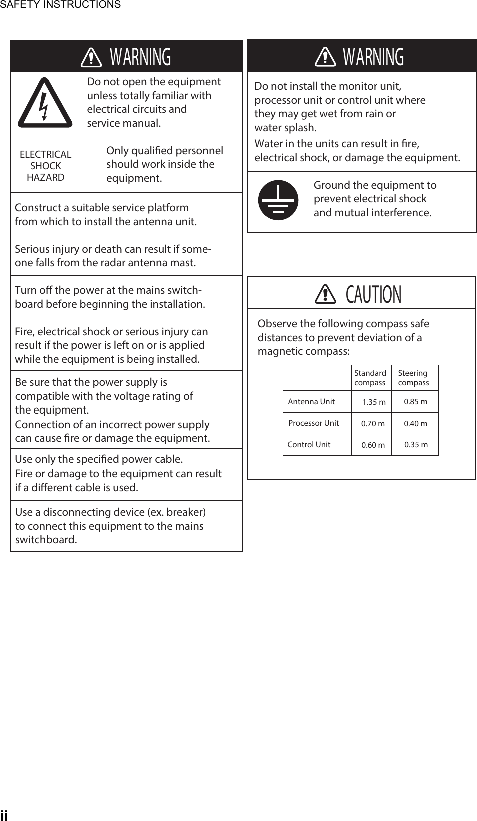
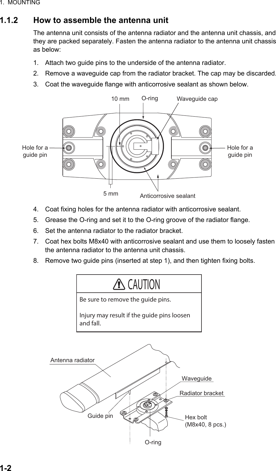


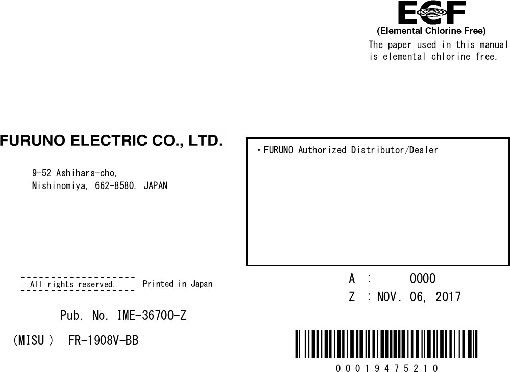
![3-13. ADJUSTMENTSAt the first power application after installation, open the protected menus to adjust the radar. Follow the procedures in this section, in the order shown, to complete the adjustment.Control unit3.1 How to Open the Protected Menus1. Open the cover of the power switch and press the switch to turn on the radar.2. Press the MENU key five times while pressing the HL OFF key.MAIN menu• SERVICE MENU• INITIALIZE menuMAIN>CONFIGURATION menu• INSTALLATION menuBRILL menu and CUSTOM menuYou can edit and save the settings for [BRL1-1] and [CUSTOM1-1].Back Up general settingsAll settings are backed up when the protected menus are unlocked. The saved settings are restored each time the power is turned on.PUSH TO SELECTEBLMENUVRMBRILLF1F2OFFCENTERHLOFFRANGESTBYTXADJUSTPower keyPower lamp Touch pad Setting knobLeft-click button Right-click button](https://usermanual.wiki/Furuno-USA/9ZWRTR102.Users-Manual-1/User-Guide-3763512-Page-25.png)
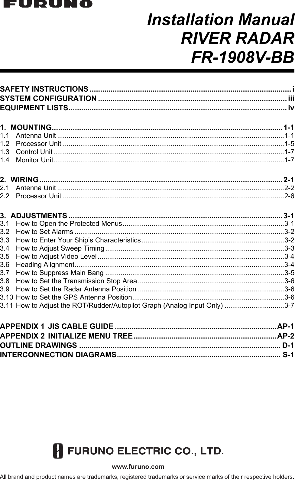
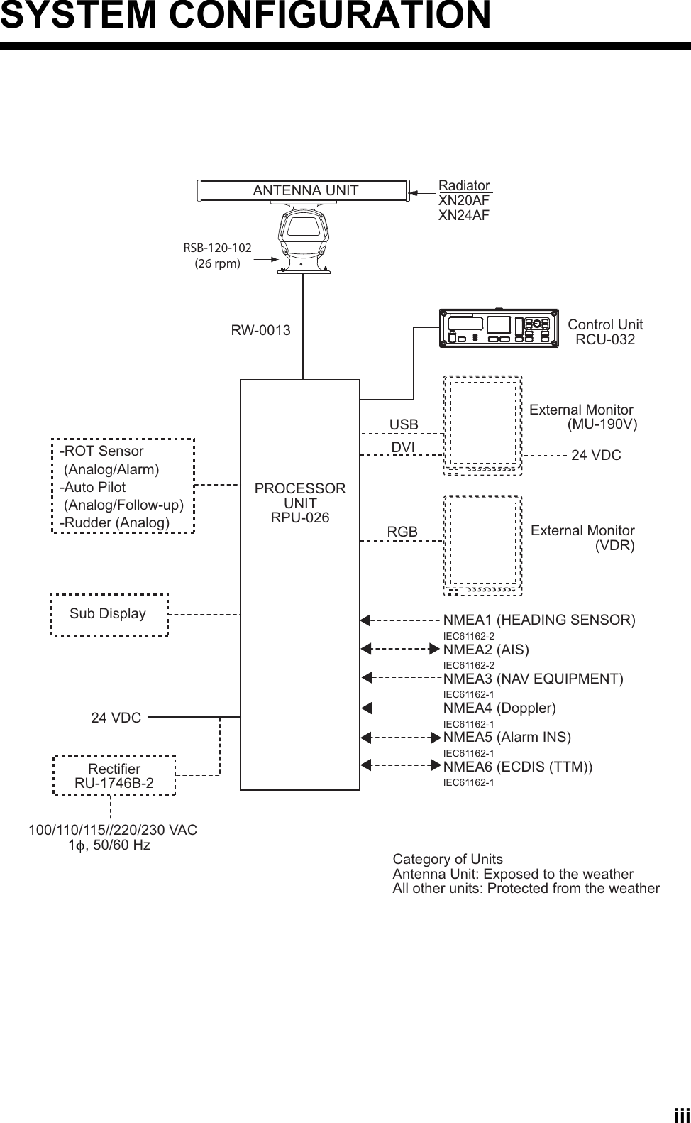
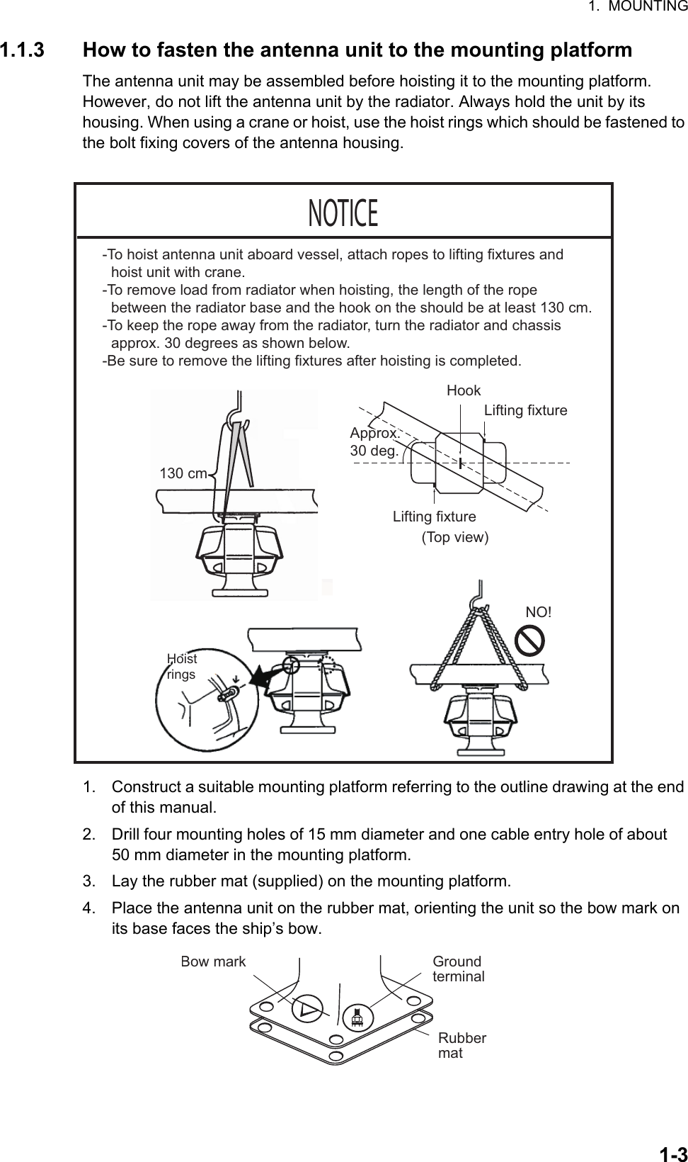
![3. ADJUSTMENTS3-23.2 How to Set AlarmsFor alarm details, see section 1.28.2 “Alarm description” in the Operator’s Manual for details.Alarm sound level1. Press the MENU key to show the main menu.2. Use the touch pad to select [13 INITIALIZE], then press the left button (click) to show the [INITIALIAZE] menu.3. Click [ALARM]→[ALARM SOUND LEVEL] menu.4. Click the appropriate sound level of an alarm among [OFF], [LOW], [MID] or [HIGH] (default: [MID]).How to activate/deactivate alarmsThe following alarms can be set on/off.• [SYSTEM ERROR]: This alarm activates when the system has an error.• [SENSOR ERROR]: This alarm activates when the sensor signal has an error.• [AIS ALARM]: This alarm activates when the AIS signal has an error.• [OTHER WARNING]: For other than the above three alarms.1. Press the MENU key to show the main menu.2. Use the touch pad to select [13 INITIALIZE], then press the left button (click) to show the [INITIALIZE] menu.3. Click [ALARM], then click the alarm whose settings you want to change.4. Click [ON] to activate the alarm. When [OFF] is selected, the alarm indication does not appear and the alarm sound is not generated.3.3 How to Enter Your Ship’s CharacteristicsShip’s length and width1. Press the MENU key to show the main menu.2. Use the touch pad to select [13 INITIALIZE], then press the left button (click) to show the [INITIALIAZE] menu.3. Click [OWN SHIP INFO] to show the [OWN SHIP INFO] menu.4. Click [LENGTH].5. Rotate the setting knob to set the ship’s length.6. Click [WIDTH].7. Rotate the setting knob to set the ship’s width.Conning position1. Open the [MAIN]>[INITIALIZE]>[OWN SHIP INFO] menu.2. Click [CONNING - BOW], then input the distance from the bow to the conning position.](https://usermanual.wiki/Furuno-USA/9ZWRTR102.Users-Manual-1/User-Guide-3763512-Page-26.png)
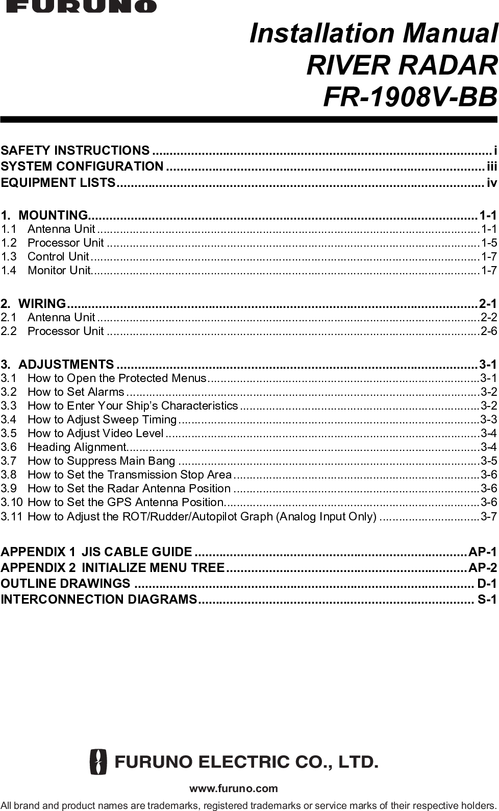
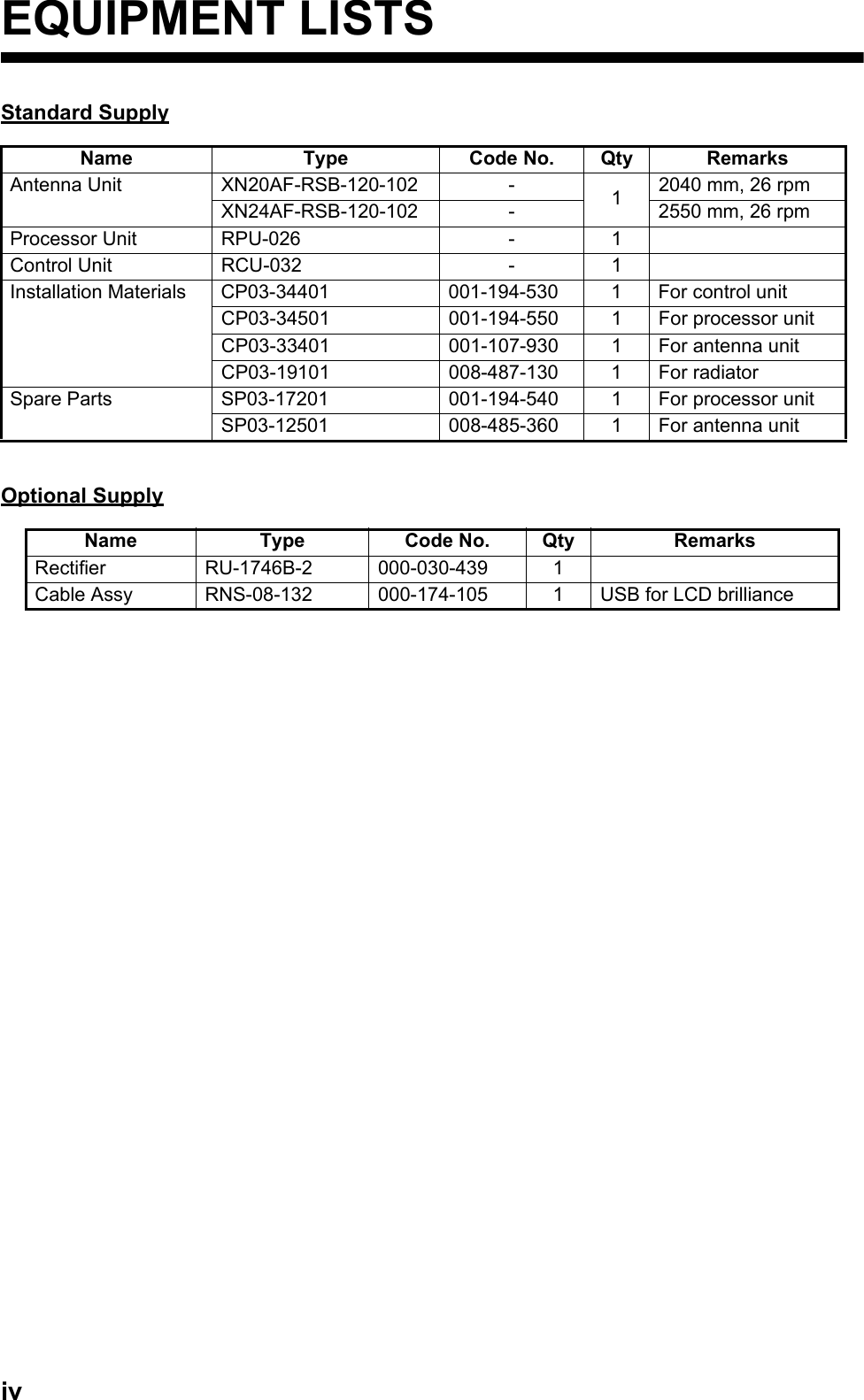
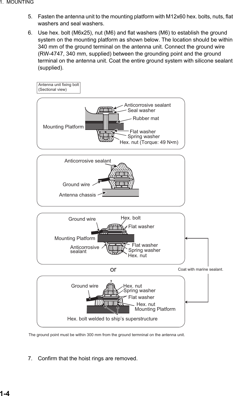
![3. ADJUSTMENTS3-33. Click [CONNING - PORT], then input the distance from the port line to the conning position.Reference pointSelect the antenna position (refer to section 3.9) or CCRP (Consistent Common Reference Point) as the radar reference point.1. Open the [MAIN]>[CONFIGURATION]>[OPERATION] menu.2. Click [REF POINT].3. Click [ANT] or [CCRP] as reference point.3.4 How to Adjust Sweep TimingSweep timing differs with respect to the length of the signal cable between the antenna unit and the processor unit. Adjust sweep timing at installation to prevent the following symptoms:• The echo of a “straight” target (for example, pier), on the 0.25 NM range, will appear on the display as being pulled inward or pushed outward. See the figures below.• The range of target echoes will also be incorrectly shown.1. Set the controls as shown below:GAIN: 80, STC: 0, RAIN: 0, FTC: OFF2. Open the [MAIN]>[CONFIGURATION] menu.3. Click [INSTALLATION] to show the [INSTALLATION] menu.L1: Ship lengthW1: Width of hullL2: Conning position (from bow)W2: Conning position (from port)W1L1L2W2Conning position(1) Correct (2) Target pushed inward (3) Target pushed outwardImage of a straight pier with different sweep timings](https://usermanual.wiki/Furuno-USA/9ZWRTR102.Users-Manual-1/User-Guide-3763512-Page-27.png)
![3. ADJUSTMENTS3-44. Click [7 TIMING ADJ] and [AUTO] to activate the automatic adjustment, which takes approx. two minutes.5. After the adjustment is completed, set the radar to the minimum range. Confirm that no echoes are “missing” at the center of the radar screen.If echoes are missing, click [9 TIMING ADJ OFFSET] and use the setting knob to adjust the timing manually.3.5 How to Adjust Video LevelSet the pulse length to LONG, confirm that tuning is stable then do the following.Note: Manual adjustment is not possible when auto adjustment is selected.1. Open the [MAIN]>[CONFIGURATION] menu.2. Click [INSTALLATION] to show the [INSTALLATION] menu.3. Click [3 VIDEO ADJ] and [AUTO] in order to automatically adjust the video level.When using the manual adjustment, refer to the following table.3.6 Heading AlignmentYou have mounted the antenna unit facing straight ahead in the direction of the bow. Therefore, a small but conspicuous target dead ahead visually should appear on the heading line (zero degrees). In practice, you will probably observe some small bearing error on the display because of the difficulty in achieving accurate initial positioning of the antenna unit. The following adjustment will compensate for this error.Length of the signal cable (m)Video level setting value](https://usermanual.wiki/Furuno-USA/9ZWRTR102.Users-Manual-1/User-Guide-3763512-Page-28.png)
![3. ADJUSTMENTS3-51. Select a stationary target echo at a range between 0.125 and 0.25 NM, preferably near the heading line.2. Operate the EBL control to bisect the target echo.3. Read the target bearing.4. Measure the bearing of the stationary target on the navigation chart and calculate the difference between the actual bearing and apparent bearing on the radar screen.5. Open the [MAIN]>[CONFIGURATION] menu.6. Click [INSTALLATION] to show the [INSTALLATION] menu.7. Click [6 HD ALIGN], and enter the bearing difference measured at step 4. The setting range is 0 to 359.9 degrees.8. Confirm that the target echo is displayed at the correct bearing on the screen.3.7 How to Suppress Main BangIf main bang appears at the screen center, suppress it as follows.1. Transmit the radar on a long range and then wait 10 minutes.2. Adjust gain to show a slight amount of noise on the display.3. Select the 0.125 NM range, and adjust STC and RAIN.TargetCorrect bearing relative to headingDisplayed positionTargetDisplayed positionCorrect bearing relative to headingAntenna mounting error toward port (fast timing of heading switch)Image appears deviated clockwise (Positive error)Antenna mounting error toward port (fast timing of heading switch)Image appears deviated clockwise (Positive error)](https://usermanual.wiki/Furuno-USA/9ZWRTR102.Users-Manual-1/User-Guide-3763512-Page-29.png)
![3. ADJUSTMENTS3-64. Open the [MAIN]>[CONFIGURATION] menu.5. Click [INSTALLATION] to show the [INSTALLATION] menu.6. Click [10 MBS], and enter a suitable value so that the main bang disappears. The setting range is 0 to 255.3.8 How to Set the Transmission Stop AreaIf there is a sector(s) on the radar display in which radar echoes cannot be received because of an obstruction near the antenna, set the sector(s) on the menu. Click [SECTOR BLANK 1] or [SECTOR BLANK 2] on the [INSTALLATION] menu and enter the referring to the illustration below.3.9 How to Set the Radar Antenna PositionSet the radar antenna position at [SCANNER POSITION] on the [INSTALLATION] menu. To set the antenna position on a barge off the ship, enter a negative value.• Bow: Input distance from the bow to the antenna unit.• Port: Set the position of antenna unit from the port line of the ship.3.10 How to Set the GPS Antenna PositionEnter the GPS antenna position from the bow and port sides at the [GPS (FRONT) POSITON] and/or [GPS (AFT) POSITON]. Correct antenna position is necessary to get accurate AIS information.HeadingStart bearingSet angleStop transmission sector](https://usermanual.wiki/Furuno-USA/9ZWRTR102.Users-Manual-1/User-Guide-3763512-Page-30.png)
![3. ADJUSTMENTS3-73.11 How to Adjust the ROT/Rudder/Autopilot Graph (Analog Input Only)The ROT (Rate of Turn), Rudder and Autopilot graphs, which appear at the top of the display, can be adjusted on the INITIALIZE menu.ROT, Rudder1. Open the [MAIN]>[INITIALIZE] menu.2. Click [ROT] or [RUDDER].3. Set the external ROT device to zero (Set rudder to 0°).4. Click [OFFSET ADJUST].5. Set the external ROT device to “test position”.6. Click [GAIN ADJUST].7. Rotate the setting knob to duplicate the external ROT (or Rudder) indication on the radar.8. Push the left button.Autopilot1. Set external autopilot to “Follow-up”.2. Open the [MAIN]>[INITIALIZE]>[AUTOPILOT] menu.3. Set the autopilot to 0°.4. Click [OFFSET ADJUST].5. Set the autopilot to max. PS (port side) or SB (starboard side).6. Click [GAIN ADJUST].7. Rotate the setting knob so that the autopilot indicator on the radar display shows the same heading indication as the associated autopilot.ROTRUDDER±300 º/min±180 ºRUDDER graphAutopilot graphROT graph](https://usermanual.wiki/Furuno-USA/9ZWRTR102.Users-Manual-1/User-Guide-3763512-Page-31.png)
![AP-2APPENDIX 2 INITIALIZE MENU TREE[INITIALIZE] menu[INITIALIZE] menuALARMROTRUDDERAUTOPILOTOWN SHIP INFOFERRY MODE (OFF, 0deg, 90deg, 180deg, 270deg)QV DISPLAY (ON, OFF)STC CURVE MONITORSYSTEM ERROR (OFF, ON)ALARM SOUND LEVEL (OFF, LOW, MID, HIGH)SENSOR ERROR (OFF, ON)AIS ALARM (OFF, ON)OTHER WARNING (OFF, ON)GRAPH (ON, OFF)OFFSET ADJUSTGAIN ADJUST (-300.0 to 300.0, 0.0)GRAPH (ON, OFF)OFFSET ADJUSTGAIN ADJUST (-180.0 to 180.0, 0.0)GRAPH (ON, OFF)OFFSET ADJUSTGAIN ADJUST (-300.0 to 300.0, 0.0)LENGTH (0 to 999 m, 0 m)WIDTH (0 to 999 m, 0 m)CONNING - BOW (0 to 999 m, 0 m)CONNING - PORT (0 to 999 m, 0 m)Default setting: Bold Italic](https://usermanual.wiki/Furuno-USA/9ZWRTR102.Users-Manual-1/User-Guide-3763512-Page-34.png)
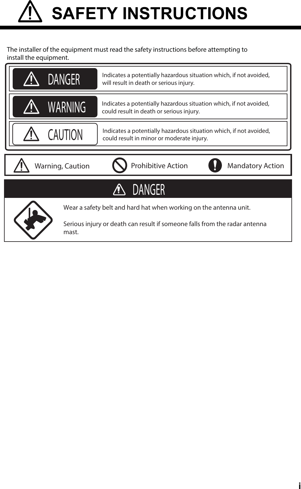
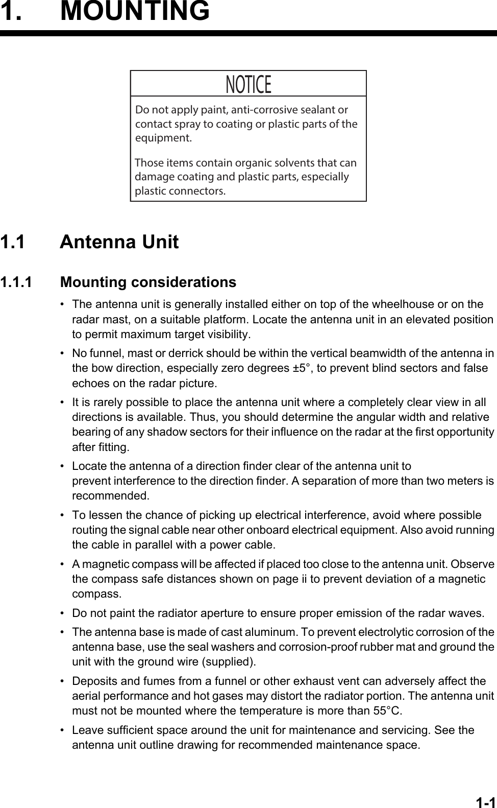
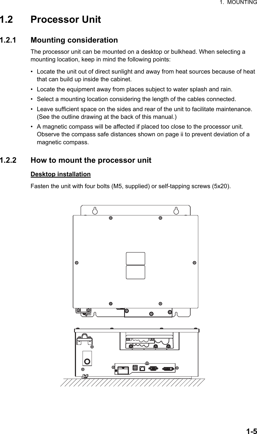
![ %$'&1$0(ྡ⛠7,7/(NJ0$666&$/($33529('&+(&.(''5$:17<$0$6$.,+0$.,5()1R':*1R :,5( &2/25 &2'( ,11(5 :,5(6 % /$5*( :,5(6 6+,(/' 6+28/' %( ()(&7,9(/< *5281'(' $7 %27+ 81,7 (1'6127( 237,21ὀグ㸰㸧࢜ࣉࢩࣙࣥࠋ㸱㸧㸦 㸧ෆࡢ࣮࢝ࣛࢥ࣮ࢻࡣෆഃࢩ࣮ࣝࢻෆࡢ⥺ࢆ♧ࡍࠋ㸲㸧ࢩ࣮ࣝࢻࡣ୧ࣘࢽࢵࢺഃ࡛࣮ࢫࡍࡿࡇࠋ10($B5'$10($B5'%10($B&20021-10($10($-10($B&2002110($B5'$10($B5'%10($B7'$10($B7'%77<&6/$77<&6/$7 +($',1* 6(1625,(&33,(&$,610($-10($B5'$10($B5'%1&77<&6/$ 1$9 (48,30(17,(&1&77<&6/$,(&10($-10($B5'$10($B5'%63((' /2*77<&6/$3377<&6/$3310($-10($B7'$10($B7'%10($B5'$10($B5'%1&10($-10($B7'$10($B7'%10($B5'$10($B5'%1&,(&,(&,16(&',6527B+527B&*1'527B$/$50B&527B$/$50B+*1'58''(5B&58''(5B+$3B)2//2:B83B+$872B3,/27B&$872B3,/27B+52758''(5$1$/2*3352758''(5$8723,/2777<&6/$333$3B)2//2:B83B&5:5$'$5 29(5/$<*1'23+'B287*1'23B%3B287*1'23B75,*B287*1'23B9,'(2B287-1+35$'$5 29(5/$<㸯㸧5+1ᡭ㓄ࠋ 35(3$5(' %< 5+1)85812 (/(&75,& &2 /7'-&& 2FW2FW5,9(5 5$'$5ࣜࣂ࣮࣮ࣞࢲ࣮,17(5&211(&7,21 ',$*5$0┦⤖⥺ᅗ)599%%'3<&7%9,'(2B,1*1'----&96%51 5(' <(/ %51 5(' *51 33/ :+7 25* %<(/ %5(' 25* %/8 33/ *5< %/. %/. %/. %*51 %%/. %:+7 %%/8 %51 *5< %25* %%/8 %<(/ %*51 5: 5:ȭ 0$;P352&(6625 81,7538ไᚚ㒊9'&'3<&ȭ+]9$& 58%,9VT021,725 81,7089⾲♧㒊 '9,- 516P%5,// &75/-,9VTࡲࡓࡣ 25(;7(51$/ 021,725እ㒊ࣔࢽࢱ࣮.(<%2$5'0286(-86% &$%/(0286(7;+91&3/B$3/B%7;B75,**1'*1'+'3909%330B&2002130B7'5'$30B7'5'%*1'*1'781,1*B,1'781,1*B&2170%6B//1$B02102725+02725+02725&02725&0$*B&85B/9/+($7(5++($7(5&3/B&781(B*$7(ᬻᐃ7(17$7,9(1(7:25.-873&$7H)25 0$,17(1$1&(5*%-&2;3&(;7(51$/ 021,725*1'$B5('$B*51$B%/8*1'*1'1&5*%B96<1&B15*%B+6<1&B11&1&*1'1&*1'1& '9,'' 6/,1.00PP&21752/ 81,7᧯స㒊(;7(51$/ 5$'$55&8,9VT56%$17(11$ 81,7✵୰⥺㒊7%7%7%5) 81,75757;+963$5(3/B$3/B%7;B75,**1'*1'781,1*B,1'781,1*B&2170%6B//1$B0210$*B&85B/9/+($7(5++($7(5&3/B&781(B*$7(+'%330B&2002130B7'5'$30B7'5'%*1'*1'9902725027250272502725S-1](https://usermanual.wiki/Furuno-USA/9ZWRTR102.Users-Manual-1/User-Guide-3763512-Page-38.png)