Furuno USA 9ZWRTR102 Transceiver for Radar User Manual IME 36700 A
Furuno USA Inc Transceiver for Radar IME 36700 A
Contents
- 1. Users Manual 1
- 2. Users Manual 2
- 3. Users Manual 3
- 4. Users Manual 4
- 5. Users Manual 5
Users Manual 1

www.furuno.com
A
ll brand and product names are trademarks, registered trademarks or service marks of their respective holders.
Installation Manual
RIVER RADAR
FR-1908V-BB
SAFETY INSTRUCTIONS ................................................................................................ i
SYSTEM CONFIGURATION .......................................................................................... iii
EQUIPMENT LISTS........................................................................................................ iv
1. MOUNTING..............................................................................................................1-1
1.1 Antenna Unit ......................................................................................................................1-1
1.2 Processor Unit ...................................................................................................................1-5
1.3 Control Unit ........................................................................................................................1-7
1.4 Monitor Unit........................................................................................................................1-7
2. WIRING....................................................................................................................2-1
2.1 Antenna Unit ......................................................................................................................2-2
2.2 Processor Unit ...................................................................................................................2-6
3. ADJUSTMENTS ......................................................................................................3-1
3.1 How to Open the Protected Menus....................................................................................3-1
3.2 How to Set Alarms .............................................................................................................3-2
3.3 How to Enter Your Ship’s Characteristics ..........................................................................3-2
3.4 How to Adjust Sweep Timing .............................................................................................3-3
3.5 How to Adjust Video Level.................................................................................................3-4
3.6 Heading Alignment.............................................................................................................3-4
3.7 How to Suppress Main Bang .............................................................................................3-5
3.8 How to Set the Transmission Stop Area............................................................................3-6
3.9 How to Set the Radar Antenna Position ............................................................................3-6
3.10 How to Set the GPS Antenna Position...............................................................................3-6
3.11 How to Adjust the ROT/Rudder/Autopilot Graph (Analog Input Only) ...............................3-7
APPENDIX 1 JIS CABLE GUIDE .............................................................................AP-1
APPENDIX 2 INITIALIZE MENU TREE ....................................................................AP-2
OUTLINE DRAWINGS ................................................................................................ D-1
INTERCONNECTION DIAGRAMS.............................................................................. S-1
Installation Manual
This page is intentionally left blank.
i
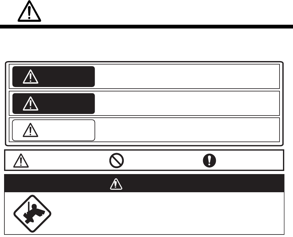
SAFETY INSTRUCTIONS
Mandatory Action
Prohibitive Action
WARNING
Indicates a potentially hazardous situation which, if not avoided,
could result in death or serious injury.
CAUTION
Indicates a potentially hazardous situation which, if not avoided,
could result in minor or moderate injury.
Warning, Caution
The installer of the equipment must read the safety instructions before attempting to
install the equipment.
DANGER
Indicates a potentially hazardous situation which, if not avoided,
will result in death or serious injury.
Wear a safety belt and hard hat when working on the antenna unit.
Serious injury or death can result if someone falls from the radar antenna
mast.
DANGER
SAFETY INSTRUCTIONS
ii
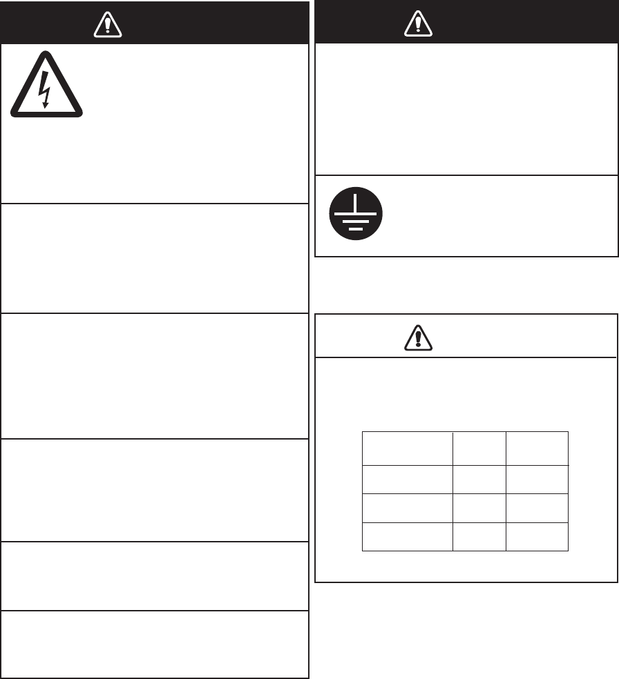
Be sure that the power supply is
compatible with the voltage rating of
the equipment.
Fire or damage to the equipment can result
if a dierent cable is used.
Connection of an incorrect power supply
can cause re or damage the equipment.
Use only the specied power cable.
Do not open the equipment
unless totally familiar with
electrical circuits and
service manual.
Only qualied personnel
should work inside the
equipment.
Construct a suitable service platform
from which to install the antenna unit.
Serious injury or death can result if some-
one falls from the radar antenna mast.
Turn o the power at the mains switch-
board before beginning the installation.
Fire, electrical shock or serious injury can
result if the power is left on or is applied
while the equipment is being installed.
ELECTRICAL
SHOCK
HAZARD
Observe the following compass safe
distances to prevent deviation of a
magnetic compass:
Antenna Unit
Standard
compass
1.35 m 0.85 m
Processor Unit 0.70 m 0.40 m
Steering
compass
Control Unit
0.60 m
0.35 m
Ground the equipment to
prevent electrical shock
and mutual interference.
Do not install the monitor unit,
processor unit or control unit where
they may get wet from rain or
water splash.
Water in the units can result in re,
electrical shock, or damage the equipment.
Use a disconnecting device (ex. breaker)
to connect this equipment to the mains
switchboard.
WARNING WARNING
CAUTION
iii
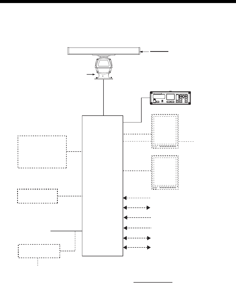
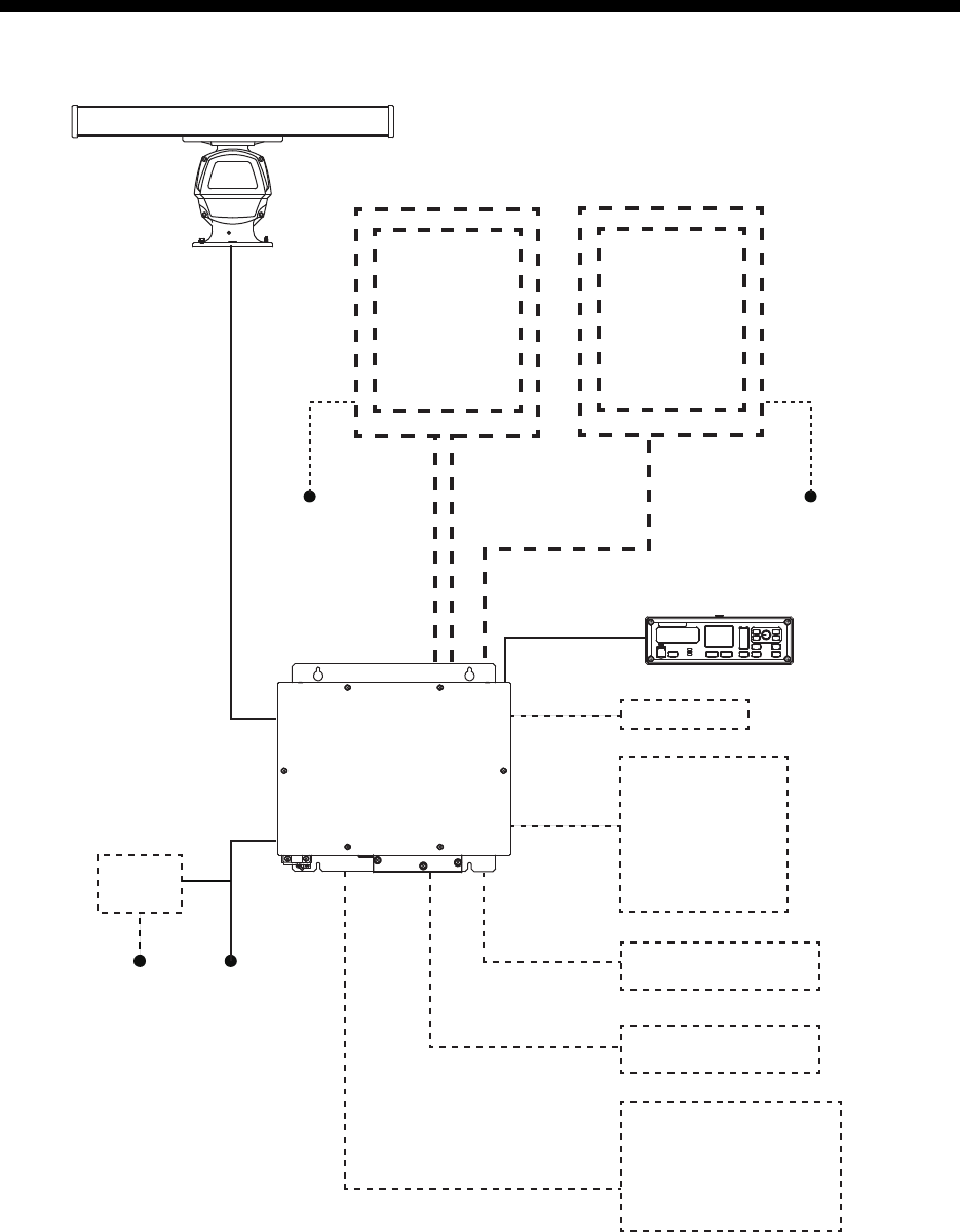
SYSTEM CONFIGURATION
ANTENNA UNIT
Category of Units
Antenna Unit: Exposed to the weather
All other units: Protected from the weather
Radiator
XN20AF
XN24AF
24 VDC
Rectifier
RU-1746B-2
100/110/115//220/230 VAC
1
φ
, 50/60 Hz
RSB-120-102
(26 rpm)
PROCESSOR
UNIT
RPU-026
Sub Display NMEA1 (HEADING SENSOR)
IEC61162-2
NMEA2 (AIS)
IEC61162-2
NMEA3 (NAV EQUIPMENT)
IEC61162-1
NMEA4 (Doppler)
IEC61162-1
NMEA5 (Alarm INS)
IEC61162-1
NMEA6 (ECDIS (TTM))
IEC61162-1
Control Unit
RCU-032
-ROT Sensor
(Analog/Alarm)
-Auto Pilot
(Analog/Follow-up)
-Rudder (Analog)
RW-0013
USB
DVI
RGB External Monitor
(VDR)
24 VDC
External Monitor
(MU-190V)
iv
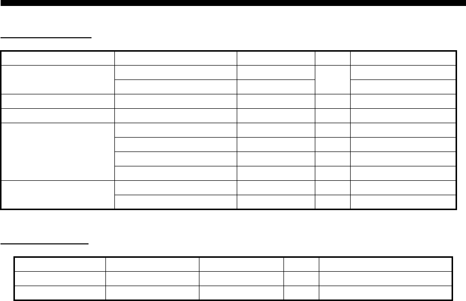
EQUIPMENT LISTS
Standard Supply
Optional Supply
Name Type Code No. Qty Remarks
Antenna Unit XN20AF-RSB-120-102 - 12040 mm, 26 rpm
XN24AF-RSB-120-102 - 2550 mm, 26 rpm
Processor Unit RPU-026 - 1
Control Unit RCU-032 - 1
Installation Materials CP03-34401 001-194-530 1 For control unit
CP03-34501 001-194-550 1 For processor unit
CP03-33401 001-107-930 1 For antenna unit
CP03-19101 008-487-130 1 For radiator
Spare Parts SP03-17201 001-194-540 1 For processor unit
SP03-12501 008-485-360 1 For antenna unit
Name Type Code No. Qty Remarks
Rectifier RU-1746B-2 000-030-439 1
Cable Assy RNS-08-132 000-174-105 1 USB for LCD brilliance

1-1
1. MOUNTING
1.1 Antenna Unit
1.1.1 Mounting considerations
• The antenna unit is generally installed either on top of the wheelhouse or on the
radar mast, on a suitable platform. Locate the antenna unit in an elevated position
to permit maximum target visibility.
• No funnel, mast or derrick should be within the vertical beamwidth of the antenna in
the bow direction, especially zero degrees ±5°, to prevent blind sectors and false
echoes on the radar picture.
• It is rarely possible to place the antenna unit where a completely clear view in all
directions is available. Thus, you should determine the angular width and relative
bearing of any shadow sectors for their influence on the radar at the first opportunity
after fitting.
• Locate the antenna of a direction finder clear of the antenna unit to
prevent interference to the direction finder. A separation of more than two meters is
recommended.
• To lessen the chance of picking up electrical interference, avoid where possible
routing the signal cable near other onboard electrical equipment. Also avoid running
the cable in parallel with a power cable.
• A magnetic compass will be affected if placed too close to the antenna unit. Observe
the compass safe distances shown on page ii to prevent deviation of a magnetic
compass.
• Do not paint the radiator aperture to ensure proper emission of the radar waves.
• The antenna base is made of cast aluminum. To prevent electrolytic corrosion of the
antenna base, use the seal washers and corrosion-proof rubber mat and ground the
unit with the ground wire (supplied).
• Deposits and fumes from a funnel or other exhaust vent can adversely affect the
aerial performance and hot gases may distort the radiator portion. The antenna unit
must not be mounted where the temperature is more than 55°C.
• Leave sufficient space around the unit for maintenance and servicing. See the
antenna unit outline drawing for recommended maintenance space.
Do not apply paint, anti-corrosive sealant or
contact spray to coating or plastic parts of the
equipment.
Those items contain organic solvents that can
damage coating and plastic parts, especially
plastic connectors.
NOTICE
1. MOUNTING
1-2
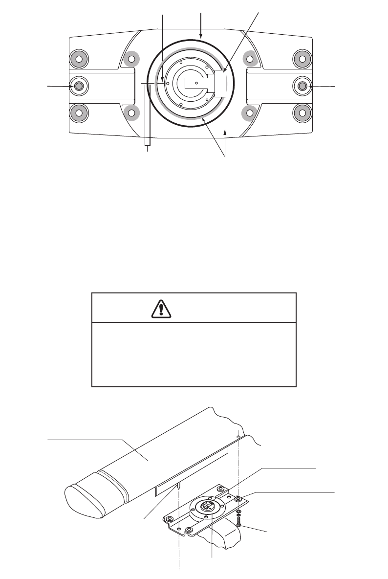
1.1.2 How to assemble the antenna unit
The antenna unit consists of the antenna radiator and the antenna unit chassis, and
they are packed separately. Fasten the antenna radiator to the antenna unit chassis
as below:
1. Attach two guide pins to the underside of the antenna radiator.
2. Remove a waveguide cap from the radiator bracket. The cap may be discarded.
3. Coat the waveguide flange with anticorrosive sealant as shown below.
4. Coat fixing holes for the antenna radiator with anticorrosive sealant.
5. Grease the O-ring and set it to the O-ring groove of the radiator flange.
6. Set the antenna radiator to the radiator bracket.
7. Coat hex bolts M8x40 with anticorrosive sealant and use them to loosely fasten
the antenna radiator to the antenna unit chassis.
8. Remove two guide pins (inserted at step 1), and then tighten fixing bolts.
Hole for a
guide pin
5 mm Anticorrosive sealant
Hole for a
guide pin
Waveguide cap
O-ring
10 mm
Be sure to remove the guide pins.
Injury may result if the guide pins loosen
and fall.
CAUTION
Antenna radiator
Waveguide
Radiator bracket
Hex bolt
(M8x40, 8 pcs.)
O-ring
Guide pin
1. MOUNTING
1-3
1.1.3 How to fasten the antenna unit to the mounting platform
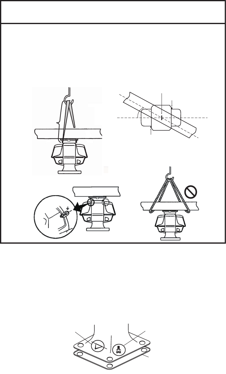
The antenna unit may be assembled before hoisting it to the mounting platform.
However, do not lift the antenna unit by the radiator. Always hold the unit by its
housing. When using a crane or hoist, use the hoist rings which should be fastened to
the bolt fixing covers of the antenna housing.
1. Construct a suitable mounting platform referring to the outline drawing at the end
of this manual.
2. Drill four mounting holes of 15 mm diameter and one cable entry hole of about
50 mm diameter in the mounting platform.
3. Lay the rubber mat (supplied) on the mounting platform.
4. Place the antenna unit on the rubber mat, orienting the unit so the bow mark on
its base faces the ship’s bow.
-To hoist antenna unit aboard vessel, attach ropes to lifting fixtures and
hoist unit with crane.
-To remove load from radiator when hoisting, the length of the rope
between the radiator base and the hook on the should be at least 130 cm.
-To keep the rope away from the radiator, turn the radiator and chassis
approx. 30 degrees as shown below.
-Be sure to remove the lifting fixtures after hoisting is completed.
130 cm
Hook
Lifting fixture
Approx.
30 deg.
Approx.
30 deg.
Lifting fixture
(Top view)
Hoist
rings
Hoist
rings
NO!
NOTICE
Ground
terminal
Rubber
mat
Bow mark
1. MOUNTING
1-4
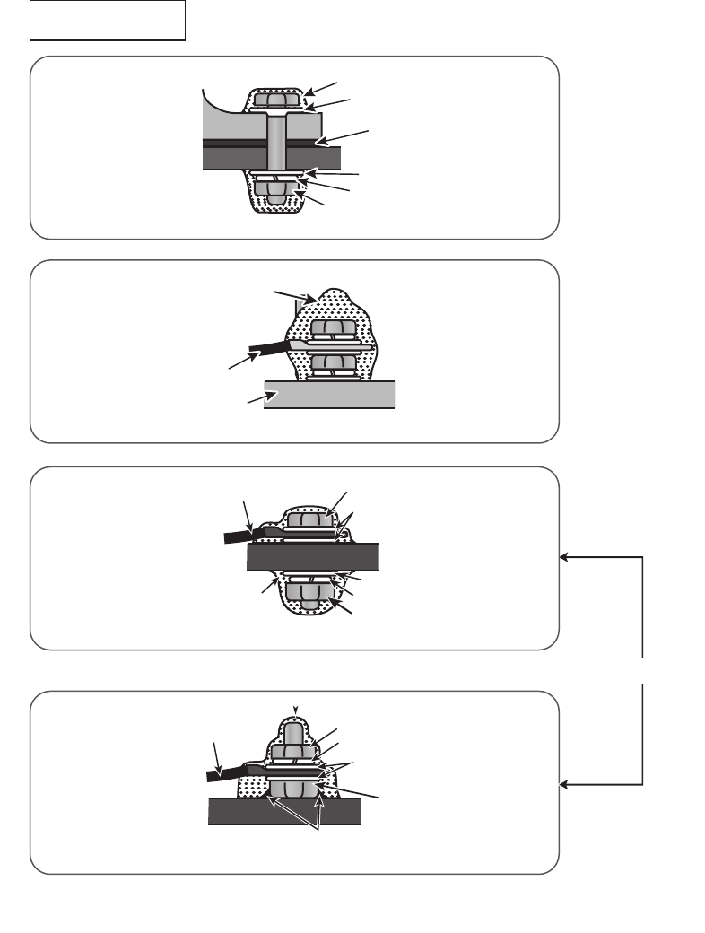
5. Fasten the antenna unit to the mounting platform with M12x60 hex. bolts, nuts, flat
washers and seal washers.
6. Use hex. bolt (M6x25), nut (M6) and flat washers (M6) to establish the ground
system on the mounting platform as shown below. The location should be within
340 mm of the ground terminal on the antenna unit. Connect the ground wire
(RW-4747, 340 mm, supplied) between the grounding point and the ground
terminal on the antenna unit. Coat the entire ground system with silicone sealant
(supplied).
7. Confirm that the hoist rings are removed.
The ground point must be within 300 mm from the ground termninal on the antenna unit.
Coat with marine sealant.
Antenna unit fixing bolt
(Sectional view)
or
Seal washer
Rubber mat
Mounting Platform
Anticorrosive sealant
Flat washer
Spring washer
Hex. nut (Torque:
49 N•m
)
Antenna chassis
Ground wire
Anticorrosive sealant
Ground wire
Anticorrosive
sealant
Hex. bolt
Flat washer
Flat washer
Spring washer
Hex. nut
Mounting Platform
Flat washer
Hex. nut
Mounting Platform
Ground wire Hex. nut
Spring washer
Hex. bolt welded to ship’s superstructure
1. MOUNTING
1-5
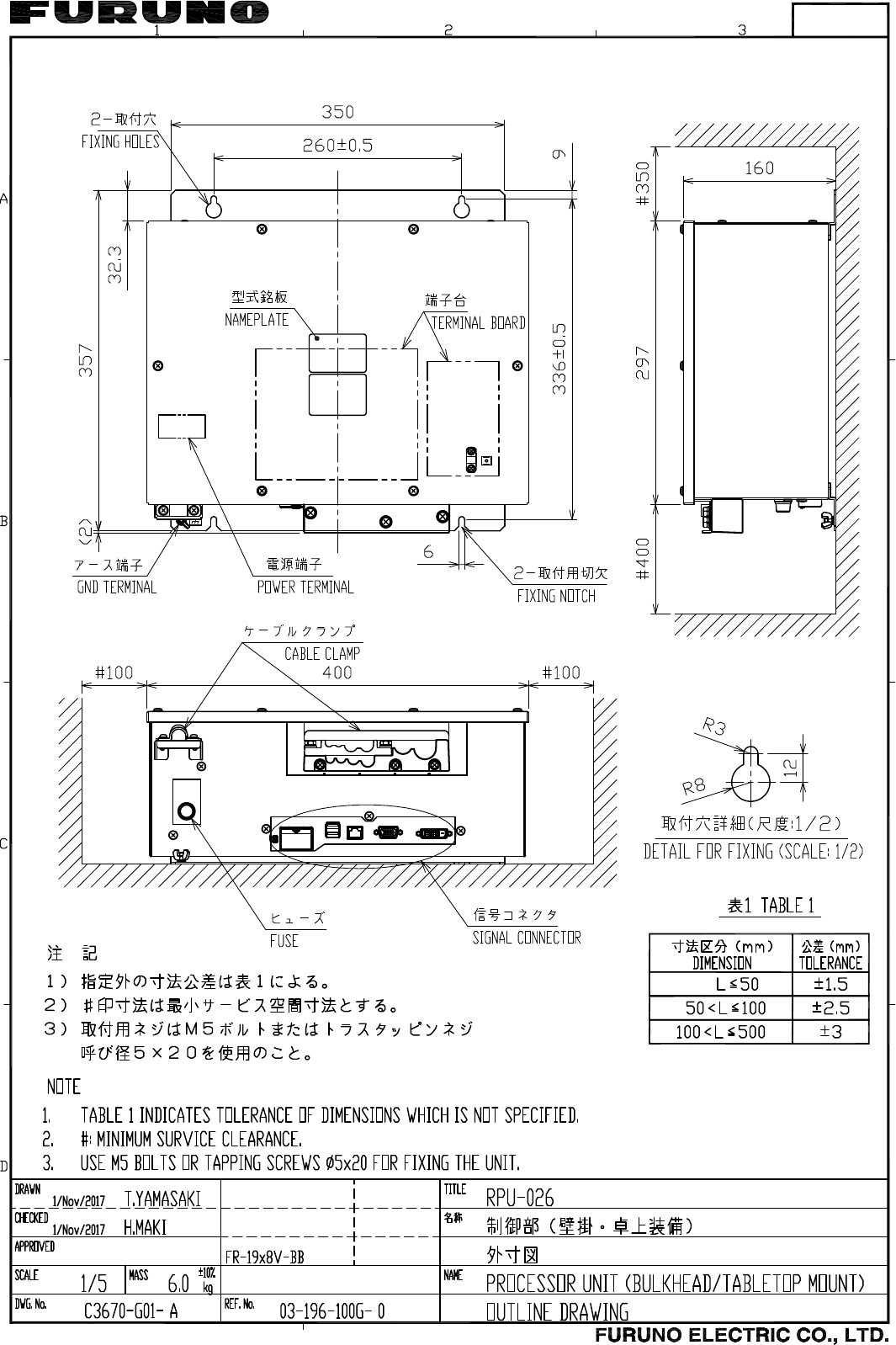
1.2 Processor Unit
1.2.1 Mounting consideration
The processor unit can be mounted on a desktop or bulkhead. When selecting a
mounting location, keep in mind the following points:
• Locate the unit out of direct sunlight and away from heat sources because of heat
that can build up inside the cabinet.
• Locate the equipment away from places subject to water splash and rain.
• Select a mounting location considering the length of the cables connected.
• Leave sufficient space on the sides and rear of the unit to facilitate maintenance.
(See the outline drawing at the back of this manual.)
• A magnetic compass will be affected if placed too close to the processor unit.
Observe the compass safe distances shown on page ii to prevent deviation of a
magnetic compass.
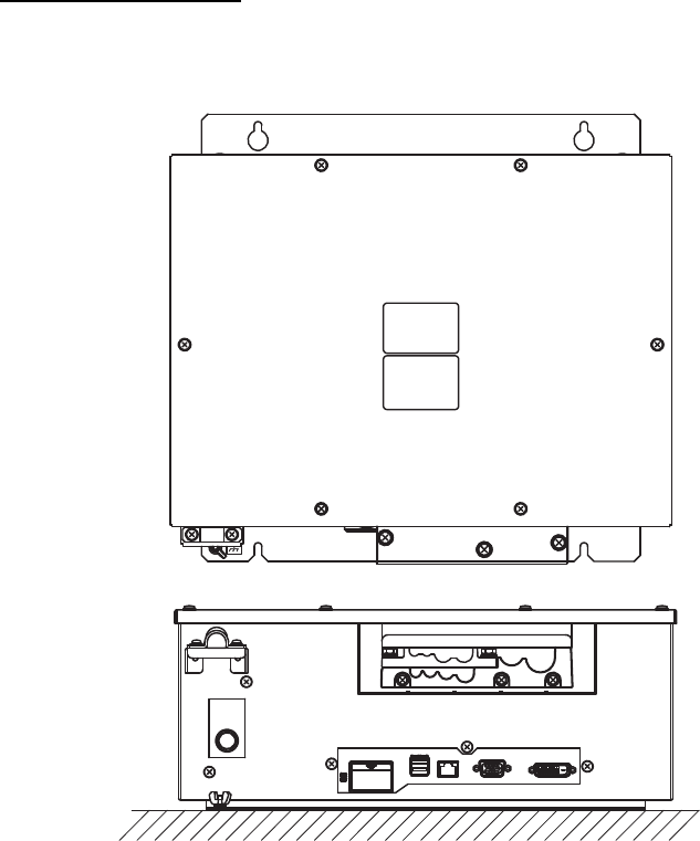
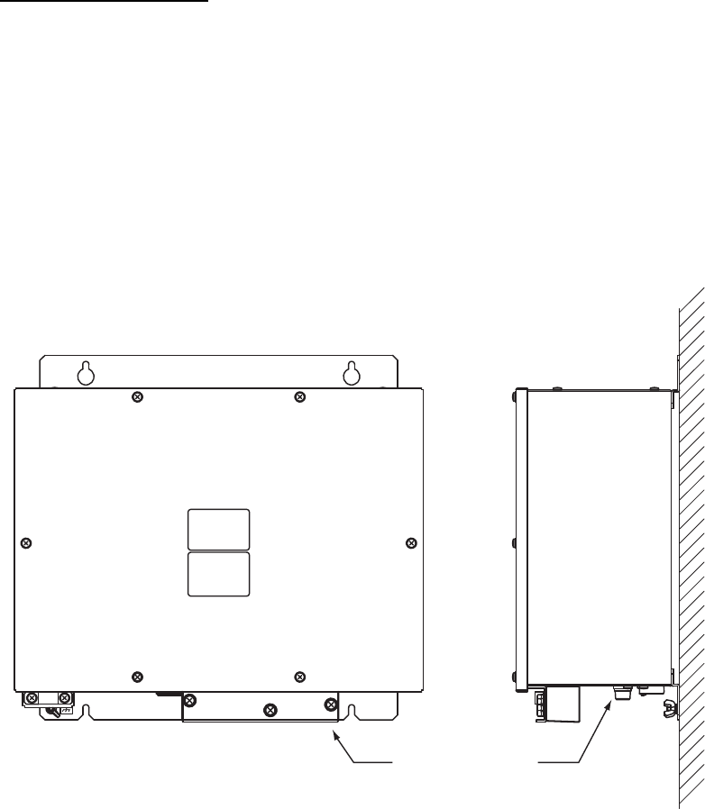
1.2.2 How to mount the processor unit
Desktop installation
Fasten the unit with four bolts (M5, supplied) or self-tapping screws (5x20).
1. MOUNTING
1-6
Bulkhead installation
Note: The cable entry side should be downward when the processor unit is mounted
on the bulkhead.
1. Mark location for four self-tapping screws if screws will be used.
2. Insert four bolts (M5, supplied) or self-tapping screws (5x20), leaving approx. 5
mm of the bolts (screws) exposed.
3. Hang the processor unit on the four bolts (screws) inserted at step 2.
4. Tighten all bolts (screws).
Cable entry side
1. MOUNTING
1-7
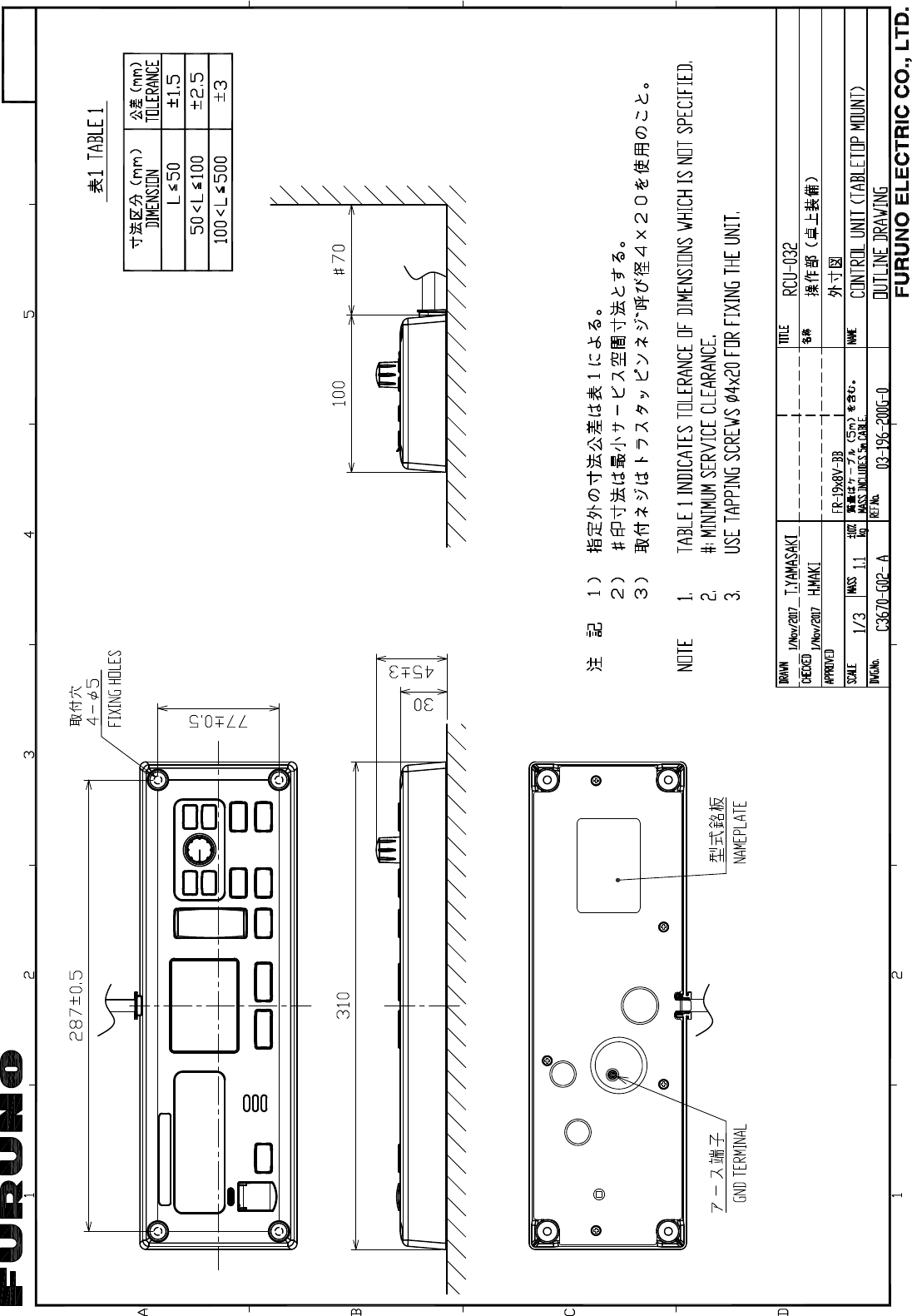
1.3 Control Unit
The control unit can be installed on a desktop. The control unit should be mounted
within five meters from the processor unit since the length of the cable connecting
them is five meters.
1. Drill four mounting holes of 5 mm diameter referring to the outline drawing at the
back of this manual.
2. Fix the control unit with four self-tapping screws (φ4) from the top of the control
unit. The M4 screws with a sufficient length for the thickness of the tabletop should
be provided locally.
3. Attach four cosmetic caps to the fixing holes on the control unit.
1.4 Monitor Unit
The monitor unit is required the vertical type indication because of output image signal
displayed on the longitudinal direction. And also, is designed assuming being
connected the MU-190V (Option). When using a monitor except MU-190V, be careful
about the next explanation.
• Brightness cannot be adjusted via a radar menu and the control unit with the general
commercial monitors. Therefore, adjust brightness with functions of the monitor
itself.
• The indication of the FR-1908V-BB cannot be flipped upside down according to the
monitor direction. For the correct indication, install the horizontal type monitor in the
state that turned 90 degrees clockwise. And then, confirm that the monitor can be
fixed in this direction beforehand.
• When using the turned horizontal monitor, the viewing angle of the right and left (top
and bottom direction in the original state) may be different. Therefore, a problem
such as a echo color and the vanity echo being different in right and left may be
occur.
Fixing hole
1. MOUNTING
1-8
This page is intentionally left blank.
2-1
2. WIRING
XN20AF
XN24AF
Monitor unit
MU-190V
Monitor unit
MU-190V
24 VDC
Control
Unit
5m
RGB
IEC 61162
IEC 61162
IEC 61162
USB mouse
-ROT 20mV/deg
-Autopilot 20mV/deg
-Rudder 1-100mV/deg
-Pilot function
-ROT alarm
DVI cable
115/230 VAC
Rectifier
Processor unit
RPU-026
USB cable
24 VDC 24 VDC
-Satellite compass
-Inland AIS
-Echo sounder
-Compass
-Autopilot
-GPS
-Wind sensor
-ROT, rudder
RSB-120-102
(26 rpm)
ANTENNA UNIT
2. WIRING
2-2
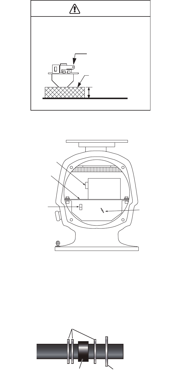
2.1 Antenna Unit
1. Open the antenna cover.
2. Disconnect plugs P821, P822, P801 and P802.
3. Unfasten the transceiver module (two bolts). Remove the transceiver module.
4. Unfasten four fixing bolts on the cable gland at the base of the antenna unit.
Remove clamping ring, rubber gasket and washers.
5. Pass the signal cable through the cable entry hole in the antenna unit mounting
platform. Trim the cable to 800 mm length from the cable gland.
6. Slide two washers, rubber gasket, washer and clamping ring onto the cable in that
order.
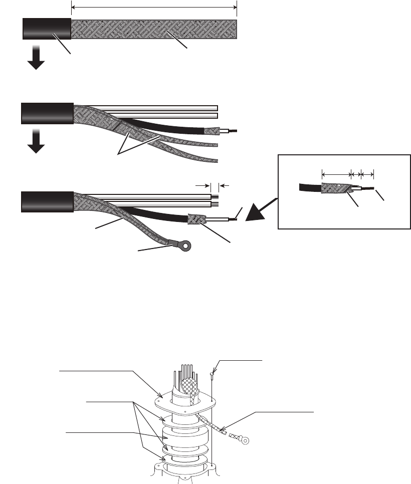
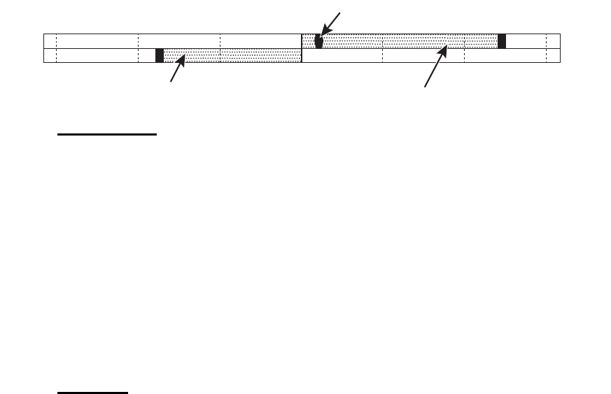
7. Fabricate the signal cable as shown in below.
1) Remove the vinyl sheath for a length by 460 mm.
Transceiver module
(magnetron inside)
Height more
than 5 cm
Non-ferrous
block
The magnetron in the transceiver module will de-
magnetize if it contacts ferrous material. When
dismounting the transceiver module, lay it on its
side or on top of non-ferrous material as shown
below.
CAUTION
J801 and J802
on 03P9506 Board
J822 on
03P9487 Board
Ground terminal
J821
Flat washer
Gasket
Clamping ring
2. WIRING
2-3
2) Unravel the outer shield to expose the cores in the outer layer. Then, expose
the cores in the inner layer. Label all inner cores to aid in identification.
3) Trim each core (except coaxial wire) considering its location on the terminal
board.
4) Trim the inner and outer shields leaving 510 mm each. Twist shields together
and attach crimp-on lug FV5.5-4 (yellow, φ4.)
5) Remove insulation of each core approx. 8 mm.
8. Fabricate the coaxial cable.
9. Pass the shield between the clamping ring and the washer as shown below.
Fasten the clamping ring with the screws.
Core
Fold back.
Coaxial cable
Inner/outer shield
8
460460
Vinyl sheath Out shield
Expose the wires then twist shield.
Attach crimp-on lug to shield.
Fold back.
Coaxial
cable
Core
14 56
Clamping ring
Washer
Rubber gasket
4-M4x16
Shield
2. WIRING
2-4
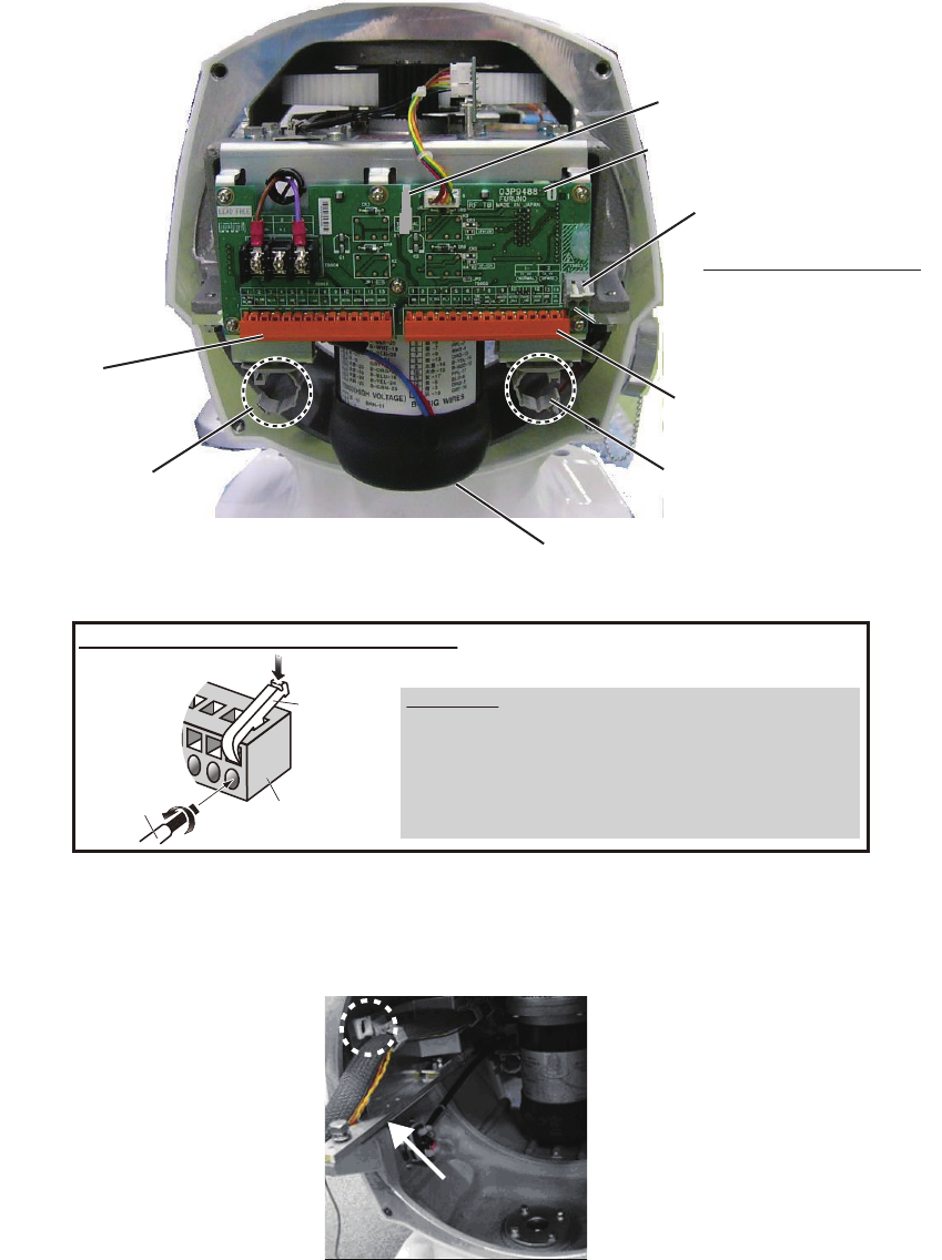
10. Connect the signal cable to the terminal board TB801, TB802 and TB803 on the
03P9488 board, referring to the interconnection diagram.
11. Pass the coaxial cable under the transceiver fixing plate (arrow) and the clamp
(dashed circle).
How to connect wires to WAGO connector
Press downward.
Terminal
opener
WAGO
connector
Wire
Twist
Procedure
1. Twist the core.
2. Set terminal opener and press it downward.
3. Insert the core into hole.
4. Remove the terminal opener.
5. Pull the wire to confirm that it is secure.
Terminal opener
03P9488 board
TB803
(High-Voltage line)
TB802
(WAGO connector)
Cable clamp
Motor
TB801
(WAGO connector)
Cable clamp
Core
entrance
Core
entrance
How to insert the core
1. Push white lever.
2. Insert a core.
3. Release white lever.
2. WIRING
2-5
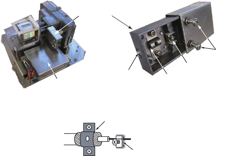
12. Detach the junction box from the transceiver unit.
13. Loosen the two screws on the junction box, then slide the cover to open the box.
Connect the coaxial cable as shown below.
14. Close the junction box and tighten the screws. Reattach the box to the transceiver
unit.
15. Reconnect the plugs disconnected at step 2.
16. Set the transceiver module to the antenna unit and push the module in until it
stops. Tighten the fixing bolts. Be sure to push in the transceiver unit until it
stops. Failure to do so may cause microwave leakage.
17. Fasten the shield wire to the wing nut on the transceiver module.
18. Confirm that all screws are tightened and all wiring is properly made. Confirm that
the waterproofing gasket, bolts and tapping holes of the antenna unit are coated
with silicone grease.
19. Close the antenna unit cover.
Junction box
Transceiver unit
Fixing
screw
Core-fixing screw
Shield-fixing clamp
Coaxial cable
entrance
Position shield beneath clamp.
Fasten core.
2. WIRING
2-6
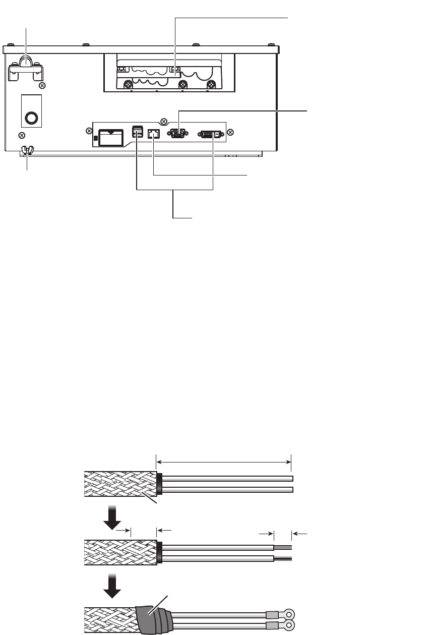
2.2 Processor Unit
How to fabricate the power cable
1. Remove the armor of the cable and the vinyl sheath by 60 mm.
2. Remove the vinyl sheath 40 mm.
3. Remove the insulation of the cores 10 mm. Fix crimp-on lugs (FV5.5-4, yellow,
supplied) to the cores.
4. Peel the paint of the armor 40 mm for to make ground connection.
5. Cover the end of the armor with vinyl tape. Lay the section where paint was peeled
on the cable clamp on the cable entry side of the processor unit. Fasten the cable
clamp.
6. Fasten the crimp-on lugs to the terminal block.
DVI-D and USB cable
(5 m, to Monitor Unit)
RGB cable (option)
(to external monitor)
TTYCSLA, antenna, control
unit and RW-4864 cables
(For clamping positions,
see the sticker on the
reverse side of the top
cover.)
LAN cable
(to other radar or HUB switch)
Ship’s power
(DPYC-6, local supply)
Ground terminal
(IV-8sq., local supply)
Armor
Vinyl tape
DPYC-6䠄DC䠅
60 mm
10
Peel paint (40 mm)
40
2. WIRING
2-7
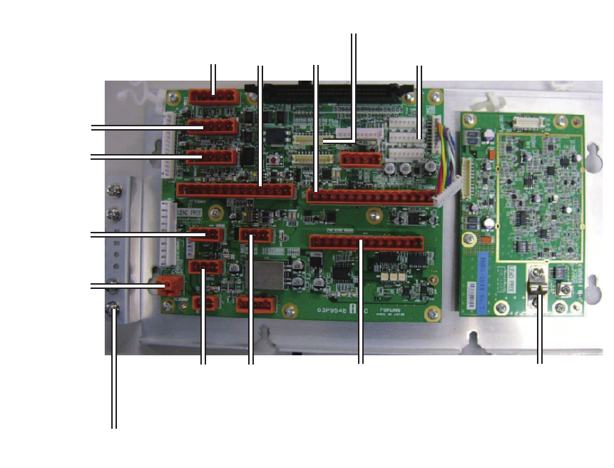
How to connect cables inside the processor unit
Connect cables from the antenna unit and optional equipment are connected to the
FRP_TB board (03P9548), inside the processor unit. Open the cover of the processor
unit to find the board.
J603 J602
Antenna cable
J617:
NMEA6 (ECDIS)
J616:
NMEA5 (INS)
J613:
NMEA2 (AIS)
J615:
NMEA4
(Doppler)
J614:
NMEA3
(Navigator)
J612:
NMEA1
(Heading)
J601:
TX-HV
J301:
VIDEO IN
(Coaxial cable)
J619:
ROT/RUDDER
J608:
RADAR OVERLAY
J604:
KEYBOARD
Attach the drain wires of
the TTYCSLA cables to here.
2. WIRING
2-8
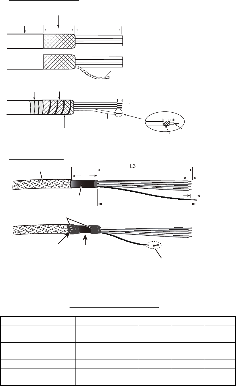
How to fabricate cables connected to the FRP_TB board
(03P9548)
Signal cable RW-0013
TTYCSLA cables
Cable lengths of L1, L2 and L3
Connector No. Cable type L1 L2 L3
J612 (NMEA1) TTYCSLA-1T 120 60 80
J613 (NMEA2) TTYCSLA-4 200 60 150
J614 (NMEA3) TTYCSLA-1 120 60 100
J615 (NMEA4) TTYCSLA-1 60 100 120
J616 (NMEA5) TTYCSLA-4 250 80 200
J617 (NMEA6) TTYCSLA-4 230 80 200
J619 (ROT/RUDDER) TTYCSLA-7 200 60 120
Vinyl sheath 240
Wind the inner shield around the outer shield.
Vinyl tape
Set this part in the cable clamp.
Connect to WAGO connector.
Coaxial cable
8
15 5 15
Conductor
Fold back shield.
Inner shield
100
(Fold back outer shield over the vinyl sheath.)
Pull out wires from the inner shield.
L1 to 3: See the table shown on next page.
Pass the vinyl tape (local suppy) onto the drain wire. Attach a
crimp-on lug (preattached to the processor unit) to the drain wire.
Fasten the crimp-on lug to its original location.
Sheath Drain wire
Crimp-on lug
8
5
L1
Armor
L2
Vinyl tape
Secure tape with cable
tie (supplied). Set this part in cable clamp.
2. WIRING
2-9
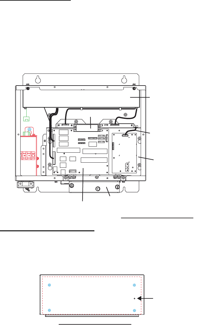
Replacement of boards
The following explanation is for the maintenance and trouble shooting. Therefore, it
is not required at the installation.
SPU Board (03P9547)
1. Unscrew six binding screws (M4) to unfasten the FRP_TB Board base, then
disconnect the ribbon cable from the board.
2. Unfasten five hex. bolts (M4) to remove the clamp panel.
3. Disconnect the VIDEO and power cables from the FRP_TB Board.
4. Lift up the FRP_TB Board base to unfasten five binding screws (M4) to remove
the SPU Board.
PWR (DC) Board (03P9497A)
When it is difficult to dismount the PWR (DC) Board chassis from the processor unit
because of the melted cooling sheet, screw a M4 x 8 (or more, local supply) screw into
the hole shown below to push out the chassis.
Clamp panel
FRP_TB Board
(03P9548)
VIDEO cable
Power cables
FRP_TB Board base
(SPU Board
under this base)
Ribbon cable
PWR (DC)
Board chassis
Processor Unit, inner view
Processor Unit, upper view
Hole to use
2. WIRING
2-10
This page is intentionally left blank.
3-1
3. ADJUSTMENTS
At the first power application after installation, open the protected menus to adjust the
radar. Follow the procedures in this section, in the order shown, to complete the
adjustment.
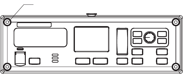
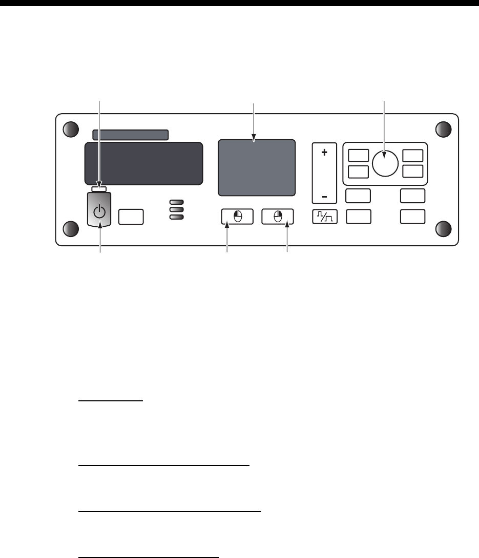
Control unit
3.1 How to Open the Protected Menus
1. Open the cover of the power switch and press the switch to turn on the radar.
2. Press the MENU key five times while pressing the HL OFF key.
MAIN menu
• SERVICE MENU
• INITIALIZE menu
MAIN>CONFIGURATION menu
• INSTALLATION menu
BRILL menu and CUSTOM menu
You can edit and save the settings for [BRL1-1] and [CUSTOM1-1].
Back Up general settings
All settings are backed up when the protected menus are unlocked. The saved
settings are restored each time the power is turned on.
PUSH TO SELECT
EBL
MENU
VRM
BRILL
F1
F2
OFF
CENTER
HL
OFF
RANGE
STBY
TX
ADJUST
Power key
Power lamp Touch pad Setting knob
Left-click button Right-click button

3. ADJUSTMENTS
3-2
3.2 How to Set Alarms
For alarm details, see section 1.28.2 “Alarm description” in the Operator’s Manual for
details.
Alarm sound level
1. Press the MENU key to show the main menu.
2. Use the touch pad to select [13 INITIALIZE], then press the left button (click) to
show the [INITIALIAZE] menu.
3. Click [ALARM]→[ALARM SOUND LEVEL] menu.
4. Click the appropriate sound level of an alarm among [OFF], [LOW], [MID] or
[HIGH] (default: [MID]).
How to activate/deactivate alarms
The following alarms can be set on/off.
• [SYSTEM ERROR]: This alarm activates when the system has an error.
• [SENSOR ERROR]: This alarm activates when the sensor signal has an error.
• [AIS ALARM]: This alarm activates when the AIS signal has an error.
• [OTHER WARNING]: For other than the above three alarms.
1. Press the MENU key to show the main menu.
2. Use the touch pad to select [13 INITIALIZE], then press the left button (click) to
show the [INITIALIZE] menu.
3. Click [ALARM], then click the alarm whose settings you want to change.
4. Click [ON] to activate the alarm. When [OFF] is selected, the alarm indication does
not appear and the alarm sound is not generated.
3.3 How to Enter Your Ship’s Characteristics
Ship’s length and width
1. Press the MENU key to show the main menu.
2. Use the touch pad to select [13 INITIALIZE], then press the left button (click) to
show the [INITIALIAZE] menu.
3. Click [OWN SHIP INFO] to show the [OWN SHIP INFO] menu.
4. Click [LENGTH].
5. Rotate the setting knob to set the ship’s length.
6. Click [WIDTH].
7. Rotate the setting knob to set the ship’s width.
Conning position
1. Open the [MAIN]>[INITIALIZE]>[OWN SHIP INFO] menu.
2. Click [CONNING - BOW], then input the distance from the bow to the conning
position.
3. ADJUSTMENTS
3-3
3. Click [CONNING - PORT], then input the distance from the port line to the conning
position.
Reference point
Select the antenna position (refer to section 3.9) or CCRP (Consistent Common
Reference Point) as the radar reference point.
1. Open the [MAIN]>[CONFIGURATION]>[OPERATION] menu.
2. Click [REF POINT].
3. Click [ANT] or [CCRP] as reference point.
3.4 How to Adjust Sweep Timing
Sweep timing differs with respect to the length of the signal cable between the antenna
unit and the processor unit. Adjust sweep timing at installation to prevent the following
symptoms:
• The echo of a “straight” target (for example, pier), on the 0.25 NM range, will appear
on the display as being pulled inward or pushed outward. See the figures below.
• The range of target echoes will also be incorrectly shown.
1. Set the controls as shown below:
GAIN: 80, STC: 0, RAIN: 0, FTC: OFF
2. Open the [MAIN]>[CONFIGURATION] menu.
3. Click [INSTALLATION] to show the [INSTALLATION] menu.
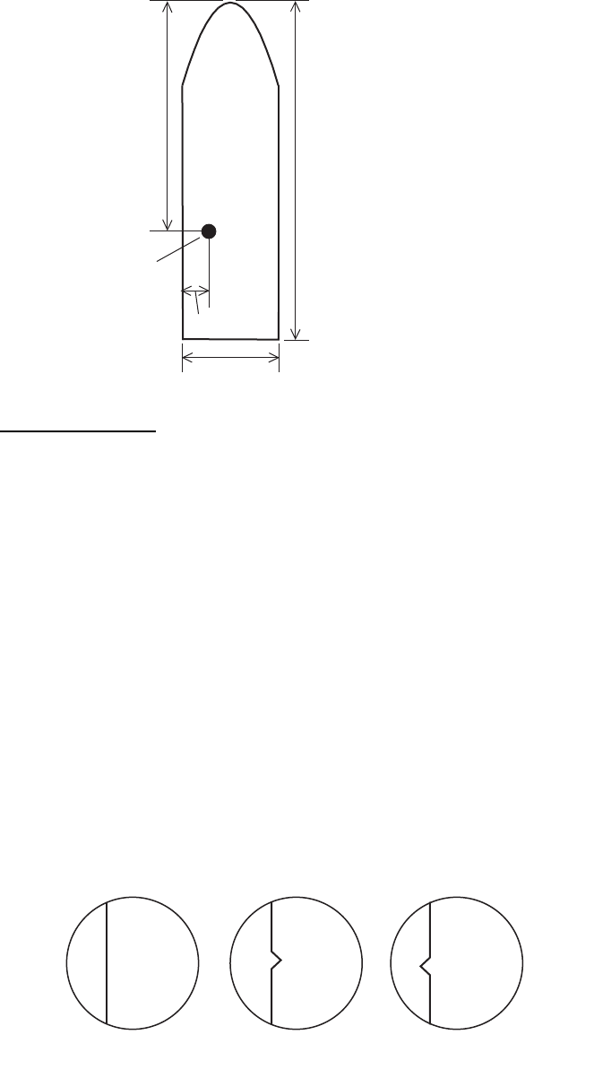
L1: Ship length
W1: Width of hull
L2: Conning position (from bow)
W2: Conning position (from port)
W1
L1
L2
W2
Conning position
(1) Correct (2) Target pushed inward (3) Target pushed outward
Image of a straight pier with different sweep timings
3. ADJUSTMENTS
3-4
4. Click [7 TIMING ADJ] and [AUTO] to activate the automatic adjustment, which
takes approx. two minutes.
5. After the adjustment is completed, set the radar to the minimum range. Confirm
that no echoes are “missing” at the center of the radar screen.
If echoes are missing, click [9 TIMING ADJ OFFSET] and use the setting knob to
adjust the timing manually.
3.5 How to Adjust Video Level
Set the pulse length to LONG, confirm that tuning is stable then do the following.
Note: Manual adjustment is not possible when auto adjustment is selected.
1. Open the [MAIN]>[CONFIGURATION] menu.
2. Click [INSTALLATION] to show the [INSTALLATION] menu.
3. Click [3 VIDEO ADJ] and [AUTO] in order to automatically adjust the video level.
When using the manual adjustment, refer to the following table.
3.6 Heading Alignment
You have mounted the antenna unit facing straight ahead in the direction of the bow.
Therefore, a small but conspicuous target dead ahead visually should appear on the
heading line (zero degrees). In practice, you will probably observe some small bearing
error on the display because of the difficulty in achieving accurate initial positioning of
the antenna unit. The following adjustment will compensate for this error.
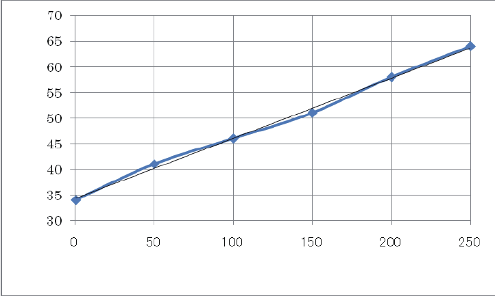
Length of the signal cable (m)
Video level setting value
3. ADJUSTMENTS
3-5
1. Select a stationary target echo at a range between 0.125 and 0.25 NM, preferably
near the heading line.
2. Operate the EBL control to bisect the target echo.
3. Read the target bearing.
4. Measure the bearing of the stationary target on the navigation chart and calculate
the difference between the actual bearing and apparent bearing on the radar
screen.
5. Open the [MAIN]>[CONFIGURATION] menu.
6. Click [INSTALLATION] to show the [INSTALLATION] menu.
7. Click [6 HD ALIGN], and enter the bearing difference measured at step 4.
The setting range is 0 to 359.9 degrees.
8. Confirm that the target echo is displayed at the correct bearing on the screen.
3.7 How to Suppress Main Bang
If main bang appears at the screen center, suppress it as follows.
1. Transmit the radar on a long range and then wait 10 minutes.
2. Adjust gain to show a slight amount of noise on the display.
3. Select the 0.125 NM range, and adjust STC and RAIN.
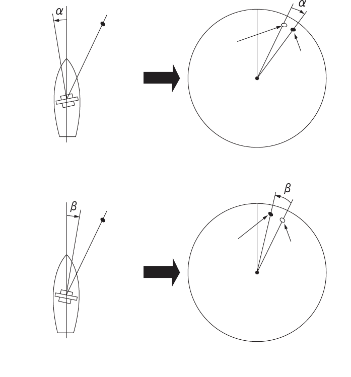
Target
Correct
bearing
relative to
heading
Displayed
position
Target
Displayed
position
Correct
bearing
relative to
heading
Antenna mounting error toward port
(fast timing of heading switch)
Image appears deviated clockwise
(Positive error)
Antenna mounting error toward port
(fast timing of heading switch)
Image appears deviated clockwise
(Positive error)
3. ADJUSTMENTS
3-6
4. Open the [MAIN]>[CONFIGURATION] menu.
5. Click [INSTALLATION] to show the [INSTALLATION] menu.
6. Click [10 MBS], and enter a suitable value so that the main bang disappears.
The setting range is 0 to 255.
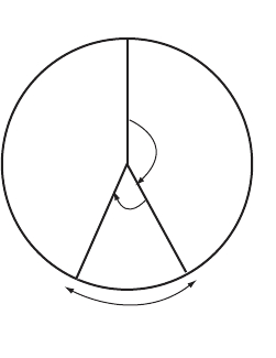
3.8 How to Set the Transmission Stop Area
If there is a sector(s) on the radar display in which radar echoes cannot be received
because of an obstruction near the antenna, set the sector(s) on the menu. Click
[SECTOR BLANK 1] or [SECTOR BLANK 2] on the [INSTALLATION] menu and enter
the referring to the illustration below.
3.9 How to Set the Radar Antenna Position
Set the radar antenna position at [SCANNER POSITION] on the [INSTALLATION]
menu. To set the antenna position on a barge off the ship, enter a negative value.
• Bow: Input distance from the bow to the antenna unit.
• Port: Set the position of antenna unit from the port line of the ship.
3.10 How to Set the GPS Antenna Position
Enter the GPS antenna position from the bow and port sides at the [GPS (FRONT)
POSITON] and/or [GPS (AFT) POSITON]. Correct antenna position is necessary to
get accurate AIS information.
Heading
Start
bearing
Set
angle
Stop transmission sector
3. ADJUSTMENTS
3-7
3.11 How to Adjust the ROT/Rudder/Autopilot Graph
(Analog Input Only)
The ROT (Rate of Turn), Rudder and Autopilot graphs, which appear at the top of the
display, can be adjusted on the INITIALIZE menu.
ROT, Rudder
1. Open the [MAIN]>[INITIALIZE] menu.
2. Click [ROT] or [RUDDER].
3. Set the external ROT device to zero (Set rudder to 0°).
4. Click [OFFSET ADJUST].
5. Set the external ROT device to “test position”.
6. Click [GAIN ADJUST].
7. Rotate the setting knob to duplicate the external ROT (or Rudder) indication on
the radar.
8. Push the left button.
Autopilot
1. Set external autopilot to “Follow-up”.
2. Open the [MAIN]>[INITIALIZE]>[AUTOPILOT] menu.
3. Set the autopilot to 0°.
4. Click [OFFSET ADJUST].
5. Set the autopilot to max. PS (port side) or SB (starboard side).
6. Click [GAIN ADJUST].
7. Rotate the setting knob so that the autopilot indicator on the radar display shows
the same heading indication as the associated autopilot.
ROT
RUDDER
±300 º/min
±180 º
RUDDER graph
Autopilot graph
ROT graph
3. ADJUSTMENTS
3-8
This page is intentionally left blank.
AP-1
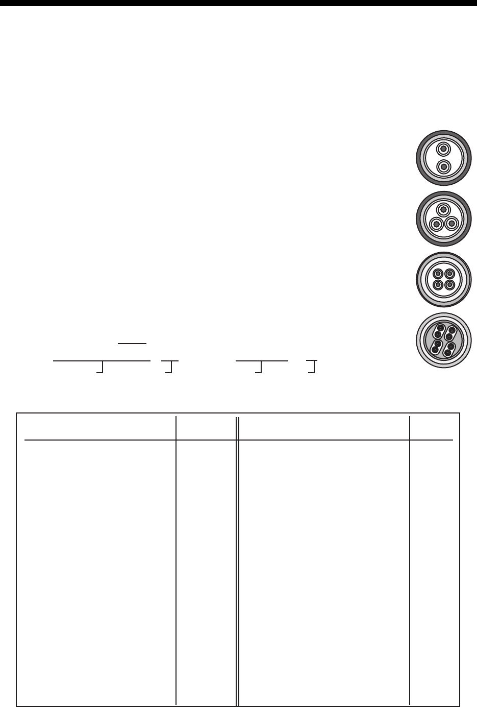
APPENDIX 1 JIS CABLE GUIDE
Core
Type Area Diameter
The following reference table lists gives the measurements of JIS cables commonly used with Furuno products:
TTYCSLA-4
MPYC-4
TPYCY
DPYCY
Cable
Diameter
DPYC-1.5 1.5mm
2
1.56mm 11.7mm
DPYC-2.5 2.5mm
2
2.01mm 12.8mm
DPYC-4 4.0mm
2
2.55mm 13.9mm
DPYC-6 6.0mm
2
3.12mm 15.2mm
DPYC-10 10.0mm
2
4.05mm 17.1mm
DPYCY-1.5 1.5mm
2
1.56mm 13.7mm
DPYCY-2.5 2.5mm
2
2.01mm 14.8mm
DPYCY-4 4.0mm
2
2.55mm 15.9mm
MPYC-2 1.0mm
2
1.29mm 10.0mm
MPYC-4 1.0mm
2
1.29mm 11.2mm
MPYC-7 1.0mm
2
1.29mm 13.2mm
MPYC-12 1.0mm
2
1.29mm 16.8mm
TPYC-1.5 1.5mm
2
1.56mm 12.5mm
TPYC-2.5 2.5mm
2
2.01mm 13.5mm
TPYC-4 4.0mm
2
2.55mm 14.7mm
TPYCY-1.5 1.5mm
2
1.56mm 14.5mm
TPYCY-2.5 2.5mm
2
2.01mm 15.5mm
TPYCY-4 4.0mm
2
2.55mm 16.9mm
TTYCS-1 0.75mm
2
1.11mm 10.1mm
TTYCS-1T 0.75mm
2
1.11mm 10.6mm
TTYCS-1Q 0.75mm
2
1.11mm 11.3mm
TTYCS-4 0.75mm
2
1.11mm 16.3mm
TTYCSLA-1 0.75mm
2
1.11mm 9.4mm
TTYCSLA-1T 0.75mm
2
1.11mm 10.1mm
TTYCSLA-1Q 0.75mm
2
1.11mm 10.8mm
TTYCSLA-4 0.75mm
2
1.11mm 15.7mm
TTYCY-1 0.75mm
2
1.11mm 11.0mm
TTYCY-1T 0.75mm
2
1.11mm 11.7mm
TTYCY-1Q 0.75mm
2
1.11mm 12.6mm
TTYCY-4 0.75mm
2
1.11mm 17.7mm
TTYCY-4S 0.75mm
2
1.11mm 21.1mm
TTYCY-4SLA 0.75mm
2
1.11mm 19.5mm
TTYCYS-1 0.75mm
2
1.11mm 12.1mm
TTYCYS-4 0.75mm
2
1.11mm 18.5mm
TTYCYSLA-1 0.75mm
2
1.11mm 11.2mm
TTYCYSLA-4 0.75mm
2
1.11mm 17.9mm
EX: TTYCYSLA - 4 MPYC - 4
Designation type # of twisted pairs Designation type # of cores
1 2 3 4 5 6 1 2 3 4
Cables listed in the manual are usually shown as Japanese Industrial Standard (JIS). Use the following guide to locate
an equivalent cable locally.
JIS cable names may have up to 6 alphabetical characters, followed by a dash and a numerical value (example:
DPYC-2.5).
For core types D and T, the numerical designation indicates the cross-sectional Area (mm2) of the core wire(s) in the
cable.
For core types M and TT, the numerical designation indicates the number of core wires in the cable.
1. Core Type
D: Double core power line
T: Triple core power line
M: Multi core
TT: Twisted pair communications
(1Q=quad cable)
2. Insulation Type
P: Ethylene Propylene
Rubber
3. Sheath Type
Y: PVC (Vinyl)
4. Armor Type
C: Steel
5. Sheath Type
Y: Anticorrosive vinyl
sheath
6. Shielding Type
S: All cores in one sheath
-S: Indivisually sheathed cores
SLA: All cores in one shield, plastic
tape w/aluminum tape
-SLA: I
ndividually shielded cores,
plastic tape w/aluminum tape
Core
Type Area Diameter
Cable
Diameter
AP-2
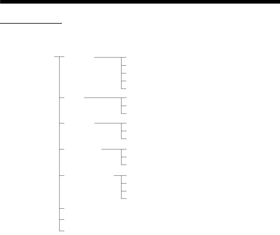
APPENDIX 2 INITIALIZE MENU TREE
[INITIALIZE] menu
[INITIALIZE]
menu
ALARM
ROT
RUDDER
AUTOPILOT
OWN SHIP INFO
FERRY MODE (OFF, 0deg, 90deg, 180deg, 270deg)
QV DISPLAY (ON, OFF)
STC CURVE MONITOR
SYSTEM ERROR (OFF, ON)
ALARM SOUND LEVEL (OFF, LOW, MID, HIGH)
SENSOR ERROR (OFF, ON)
AIS ALARM (OFF, ON)
OTHER WARNING (OFF, ON)
GRAPH (ON, OFF)
OFFSET ADJUST
GAIN ADJUST (-300.0 to 300.0, 0.0)
GRAPH (ON, OFF)
OFFSET ADJUST
GAIN ADJUST (-180.0 to 180.0, 0.0)
GRAPH (ON, OFF)
OFFSET ADJUST
GAIN ADJUST (-300.0 to 300.0, 0.0)
LENGTH (0 to 999 m, 0 m)
WIDTH (0 to 999 m, 0 m)
CONNING - BOW (0 to 999 m, 0 m)
CONNING - PORT (0 to 999 m, 0 m)
Default setting: Bold Italic
12/Oct/2012H.MAKI
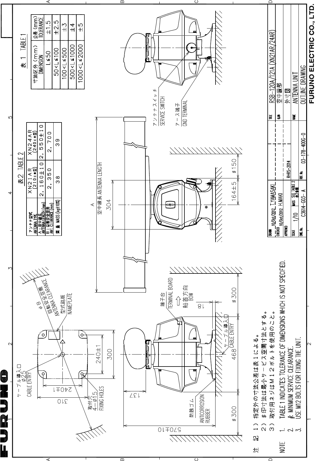
D-1
D-
2/Nov/2017 H.MAKI
D-
2/Nov/2017 H.MAKI
%
$
'
&
1$0(
ྡ⛠
7,7/(
NJ
0$666&$/(
$33529('
&+(&.('
'5$:1
7<$0$6$.,
+0$.,
5()1R':*1R
:,5( &2/25 &2'( ,11(5 :,5(6 % /$5*( :,5(6
6+,(/' 6+28/' %( ()(&7,9(/< *5281'(' $7 %27+ 81,7 (1'6
127(
237,21
ὀグ
㸰㸧࢜ࣉࢩࣙࣥࠋ
㸱㸧㸦 㸧ෆࡢ࣮࢝ࣛࢥ࣮ࢻࡣෆഃࢩ࣮ࣝࢻෆࡢ⥺ࢆ♧ࡍࠋ
㸲㸧ࢩ࣮ࣝࢻࡣ୧ࣘࢽࢵࢺഃ࡛࣮ࢫࡍࡿࡇࠋ
10($B5'$
10($B5'%
10($B&20021
-
10($
10($
-
10($B&20021
10($B5'$
10($B5'%
10($B7'$
10($B7'%
77<&6/$
77<&6/$7 +($',1* 6(1625
,(&
3
3
,(&
$,6
10($
-
10($B5'$
10($B5'%
1&
77<&6/$ 1$9 (48,30(17
,(&
1&
77<&6/$
,(&
10($
-
10($B5'$
10($B5'%
63((' /2*
77<&6/$
3
3
77<&6/$
3
3
10($
-
10($B7'$
10($B7'%
10($B5'$
10($B5'%
1&
10($
-
10($B7'$
10($B7'%
10($B5'$
10($B5'%
1&
,(&
,(&
,16
(&',6
527B+
527B&
*1'
527B$/$50B&
527B$/$50B+
*1'
58''(5B&
58''(5B+
$3B)2//2:B83B+
$872B3,/27B&
$872B3,/27B+
52758''(5
$1$/2*
3
3
52758''(5
$8723,/27
77<&6/$
3
3
3
$3B)2//2:B83B&
5:
5$'$5 29(5/$<
*1'
23+'B287
*1'
23B%3B287
*1'
23B75,*B287
*1'
23B9,'(2B287
-1+3
5$'$5 29(5/$<
㸯㸧5+1ᡭ㓄ࠋ
35(3$5(' %< 5+1
)85812 (/(&75,& &2 /7'
-
&&
2FW
2FW
5,9(5 5$'$5
ࣜࣂ࣮࣮ࣞࢲ࣮
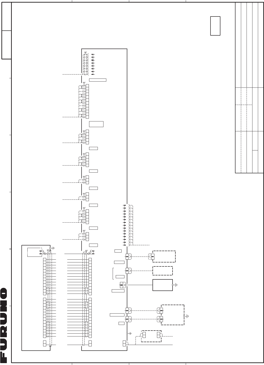
,17(5&211(&7,21 ',$*5$0
┦⤖⥺ᅗ
)599%%
'3<&
7%
9,'(2B,1
*1'
-
-
-
-
&96
%51
5('
<(/
%51
5('
*51
33/
:+7
25*
%<(/
%5('
25*
%/8
33/
*5<
%/.
%/.
%/.
%*51
%%/.
%:+7
%%/8
%51
*5<
%25*
%%/8
%<(/
%*51
5:
5:ȭ 0$;P
352&(6625 81,7
538
ไᚚ㒊
9'&
'3<&
ȭ+]
9$&
58%
,9VT
021,725 81,7
089
⾲♧㒊 '9,
-
516P
%5,// &75/
-
,9VT
ࡲࡓࡣ 25
(;7(51$/ 021,725
እ㒊ࣔࢽࢱ࣮
.(<%2$5'
0286(
-
86% &$%/(
0286(
7;+9
1&
3/B$
3/B%
7;B75,*
*1'
*1'
+'
39
09
%3
30B&20021
30B7'5'$
30B7'5'%
*1'
*1'
781,1*B,1'
781,1*B&217
0%6B/
/1$B021
02725+
02725+
02725&
02725&
0$*B&85B/9/
+($7(5+
+($7(5&
3/B&
781(B*$7(
ᬻᐃ
7(17$7,9(
1(7:25.
-
873&$7H
)25 0$,17(1$1&(
5*%
-
&2;3&
(;7(51$/ 021,725
*1'
$B5('
$B*51
$B%/8
*1'
*1'
1&
5*%B96<1&B1
5*%B+6<1&B1
1&
1&
*1'
1&
*1'
1&
'9,'' 6/,1.00
P
P
&21752/ 81,7
᧯స㒊
(;7(51$/ 5$'$5
5&8
,9VT
56%
$17(11$ 81,7
✵୰⥺㒊
7%
7%
7%
5) 81,7
575
7;+9
63$5(
3/B$
3/B%
7;B75,*
*1'
*1'
781,1*B,1'
781,1*B&217
0%6B/
/1$B021
0$*B&85B/9/
+($7(5+
+($7(5&
3/B&
781(B*$7(
+'
%3
30B&20021
30B7'5'$
30B7'5'%
*1'
*1'
9
9
02725
02725
02725
02725
S-1

The paper used in this manual
is elemental chlorine free.
・FURUNO Authorized Distributor/Dealer
9-52 Ashihara-cho,
Nishinomiya, 662-8580, JAPAN
A
:
0000
Printed in Japan
All rights reserved.
Z
:
NOV
.
06, 2017
Pub. No.
IME-36700-Z
(
MISU
)
FR-1908V-BB
0 0 0 1 9 4 7 5 2 1 0