Furuno USA 9ZWRTR102 Transceiver for Radar User Manual OME 36700 A
Furuno USA Inc Transceiver for Radar OME 36700 A
Contents
- 1. Users Manual 1
- 2. Users Manual 2
- 3. Users Manual 3
- 4. Users Manual 4
- 5. Users Manual 5
Users Manual 3
1. OPERATION
1-21
1.17 FTC (Fast Time Constant)
If you can not effectively suppress rain
clutter with the rain clutter control, use the
FTC function. In adverse weather, clouds,
rain or snow produce spray-like spurious
echoes which impair target detection over
a long distance. These echoes can be
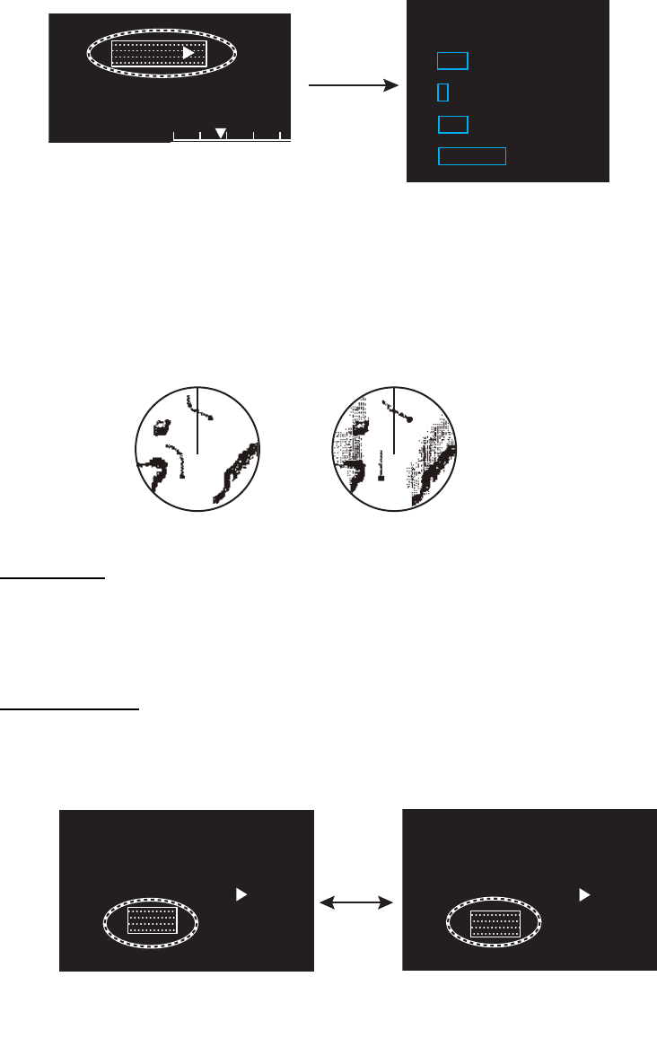
suppressed by turning on the FTC circuit. There are two FTC settings, [FTC1] and
[FTC2]. [FTC2] provides increased rain clutter suppression.
Click the [FTC] icon at the bottom right corner on the screen to select an appropriate
FTC setting.
FTC PRESET
The [FTC PRESET] function, when active, applies the FTC a little stronger than
normal. The combination effect of the [FTC PRESET] and [FTC] functions is shown as
below.
Set the [FTC PRESET] function as follows.
1. Open [MAIN MENU], click [ECHO].
2. Click [FTC PRESET].
3. Click [ON] to activate the [FTC PRESET] function.
1.18 How to Measure the Range to a Target (VRM)
You can measure the range to a target by two methods: fixed range rings and the VRM
(Variable Range Marker).
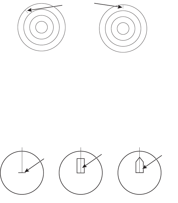
How to measure the range with the fixed range rings
Use the fixed range rings to get a rough estimate of the range to a target. The fixed
range rings are the concentric solid circles about your ship. The number of rings
changes with the selected range scale. The interval of the range ring is displayed at
the upper-left corner of the screen. Count the number of rings between the center of
the display and the target. Check the range ring interval and measure the distance of
the echo from the nearest ring.
How to measure the range with a VRM
There are two VRMs, VRM1 and VRM2. The VRMs are dashed so that you can
identify them from the fixed range rings. You can identify VRM1 from VRM2 by the
lengths of their dashes. The dashes of the VRM1 are shorter than those of the VRM2.
Effect [FTC PRESET]
[OFF] [ON]
[FTC]
[OFF] – low
[FTC1] mid-low mid-high
[FTC2] mid-high high
CAUTION
Switch off FTC if your objective is to
receive a radar beacon.
1. OPERATION
1-22
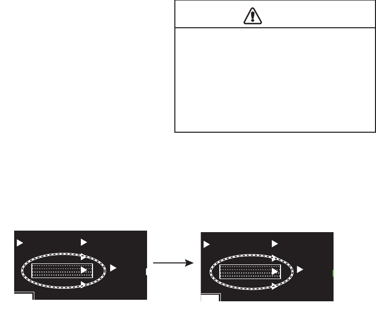
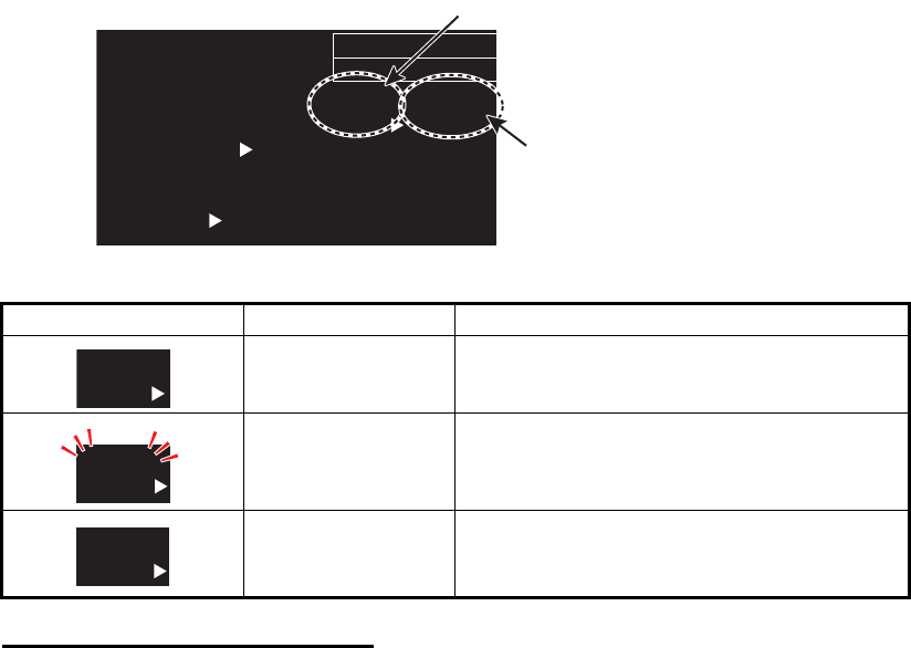
1. Click the [VRM] icon to display the VRM. If the VRM already appears, go to step 2.
2. Click the [VRM] icon. The icon turns yellow.
3. Move the cursor to align the VRM with the inner edge of the target then click there
to anchor the VRM.
4. Read the distance at the bottom of the screen. Each VRM ring (VRM1 or VRM2)
remains at the same geographical distance when you change the display range.
The size of the VRM ring changes in proportion to the selected range scale.
5. To delete a VRM, put the cursor on the appropriate VRM indication then long
press the left button (or long press the VRM key).
Note: If the corresponding EBL is displayed, the VRM is deleted and the value of
VRM remains.
1.19 How to Measure the Bearing to a Target (EBL)
Use the Electronic Bearing Line (EBL) to take a bearing of a target. There are two
EBLs, EBL1 and EBL2. Each EBL is a straight dashed line from the center of the
screen to the edge. The dashes of the EBL1 are shorter than those of the EBL2.
How to measure the bearing with an EBL
1. Click the [EBL] icon to display the EBL. If the EBL already appears, go to step 2.
2. Click the [EBL] icon ([EBL1] or [EBL2]). The icon turns yellow.
3. Put the cursor on the center of the target then click there to anchor the EBL. Read
the bearing at the bottom of the screen.
4. To delete an EBL, put the cursor on the appropriate EBL indication then long press
the left button (or long press the EBL key).
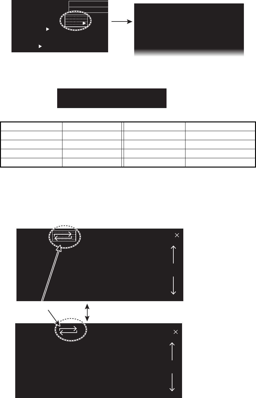
How to select bearing reference
The bearing reference can be selected to True or Relative. Click the bearing reference
icon to the right of the bearing indication.
[VRM] icon
(at the bottom right of the screen) Highlighted yellow
Click
AIS
FLT►
VRM2
0.160
NAV
0 160
NM
LIST
►
NM
NM
M
M
M
AUTO
T
VRM1 0.000
VRM1 0.000
AIS
FLT►
VRM2
0.160
NAV
0 160
LIST
►
NM
NM
M
M
M
AUTO
T
VRM1 1.567
VRM1 1.567
NM
NM
>
“>” means active.
>
Highlighted yellow
Click
EBL2
82.9°
NAV
0.160
T
T
km
EBL1
123.4°
EBL1
123.4°
EBL2
82.9°
NAV
0.160
T
T
km
EBL1
123.4°
EBL1
123.4°
>
[EBL] icon
(at the bottom left of the screen) “>” means active.
T
EBL1
123.4°
EBL1
123.4°
[T]: True
R
EBL1
123.4°
EBL1
123.4°
[R]: Relative
Click
1. OPERATION
1-23
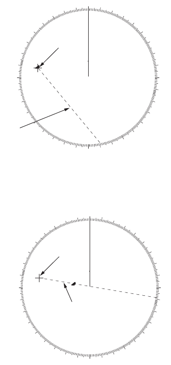
1.20 Offset EBL
How to offset an EBL
You can move the EBL origin to a desired location as follows:
1. Put the cursor on the appropriate [EBL] icon to activate the EBL. The mark (>),
which denotes active EBL, moves to the [EBL] icon selected. The example below
shows how to activate the EBL1.
2. Right-click anywhere in the radar display to open [CURSOR MENU].
3. Click [EBL OFFSET].
4. Click anywhere in the radar display to move the EBL origin with cursor.
5. Click the point where to fix the EBL origin there.
6. To return the EBL origin to own ship position, click anywhere in the radar display
again.
7. Right-click to quit the offset EBL.
1.20.1 How to measure the range and bearing between two targets
You can move the origin of the EBL to measure the range and bearing between two
targets.
1. Click the [EBL1] icon to activate EBL1. If the EBL already appears, go to step 2.
2. Right-click anywhere in the radar display to open [CURSOR MENU].
3. Click [EBL OFFSET].
4. Click anywhere in the radar display to move
the EBL origin.
Note: If EBL1 is already off-centered, the ori-
gin of the EBL moves to own ship's position
once. In this case, click anywhere in the radar
display again.
5. Click the center of the target A to fix the EBL.
6. Right-click to quit the offset EBL.
7. Click the [EBL1] icon to change the
bearing. The [EBL1] icon turns
yellow.
EBL2
82.9°
T
T
EBL1
123.4°
EBL1
123.4°
>Put the cursor on
the [EBL1] icon.
EBL2
82.9°
T
T
EBL1
123.4°
EBL1
123.4°
>
EBL2 is active.
“>” means active.
“>” move to the
[EBL1] icon
EBL origin
Target ATarget A
EBL1EBL1
Target BTarget B
82 9°
T
EBL1
123.4°
EBL1
123.4°
82 9°
T
EBL1
123.4°
EBL1
123.4°
Click
Highlighted yellow
1. OPERATION
1-24
8. Click the center of the target B.
The EBL bisects target B.
9. Click the [VRM1] icon to change the
range. The [VRM1] icon turns yellow.
[VRM1] is linked to [EBL1]; [VRM2] is
linked to [EBL2].
10. Click the inner edge of the target B.
The VRM adjusts to put the VRM ring
on the target B. The point selected at
step 4 is the center of VRM.
11. Read the bearing at the [EBL] icon and the range at the [VRM] icon.
12. Do the same procedure for [EBL2] and [VRM2] to measure the range and bearing
between two other targets (target C and D), use EBL2 and VRM2 similarly.
EBL origin
Target A
Target A
EBL1
EBL1
Target B
Target B
82 9°
T
VRM1 0.550NM
VRM1 0.550NM
82 9°
T
VRM1 0.550NM
VRM1 0.550NM
Click
Yellow
EBL origin
Target BTarget B
Target ATarget A
VRM1VRM1
EBL origin
Target B
Target B
Target A
Target A
VRM1
VRM1
EBL origin
EBL origin
Target B
Target B
EBL 2
EBL 2
VRM 2
VRM 2
EBL 1
EBL 1
VRM 1
VRM 1
EBL1 45.0
°
R
327.0
°
R
VRM1
0.550NM
0.850NM
Target A
Target A
Target D
Target D
Target C
Target C
Range/bearing between
targets A and B
Range/bearing between
targets C and D
EBL2 VRM2
EBL origin
EBL origin
1. OPERATION
1-25
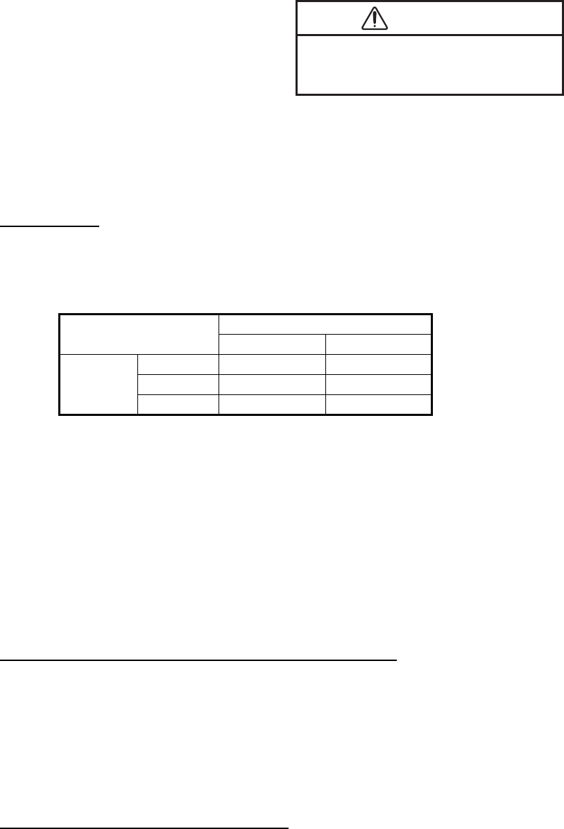
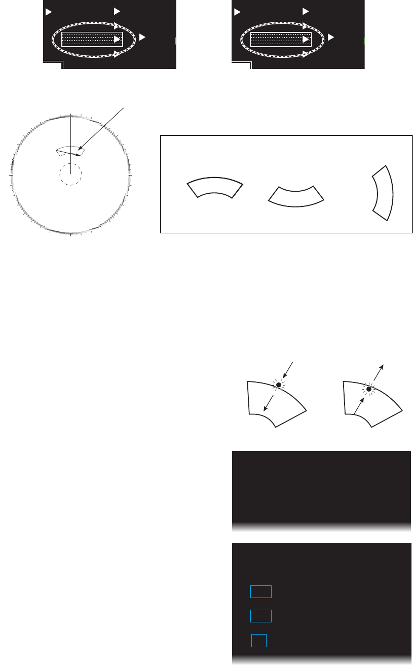
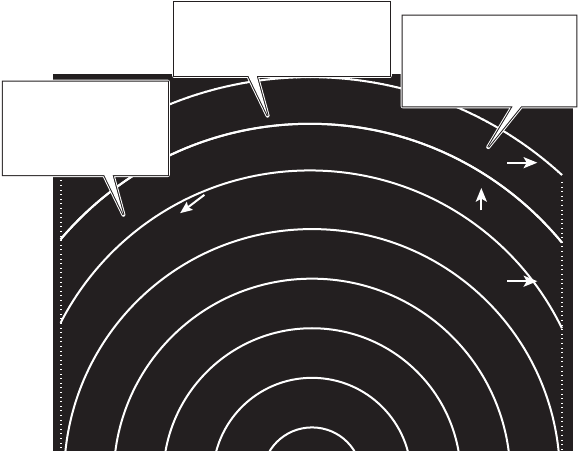
1.20.2 Collision assessment by offset EBL
The origin of the EBL can be moved to enable measurement of range and bearing
between any targets. This function is also useful for assessment of the potential risk
of collision.
1. Move the EBL origin on the target A,
following "How to offset an
EBL" on page 1-23.
2. Right-click to quit the offset EBL.
3. After waiting for a few minutes, click
the appropriate EBL icon to operate the EBL. The icon turns yellow.
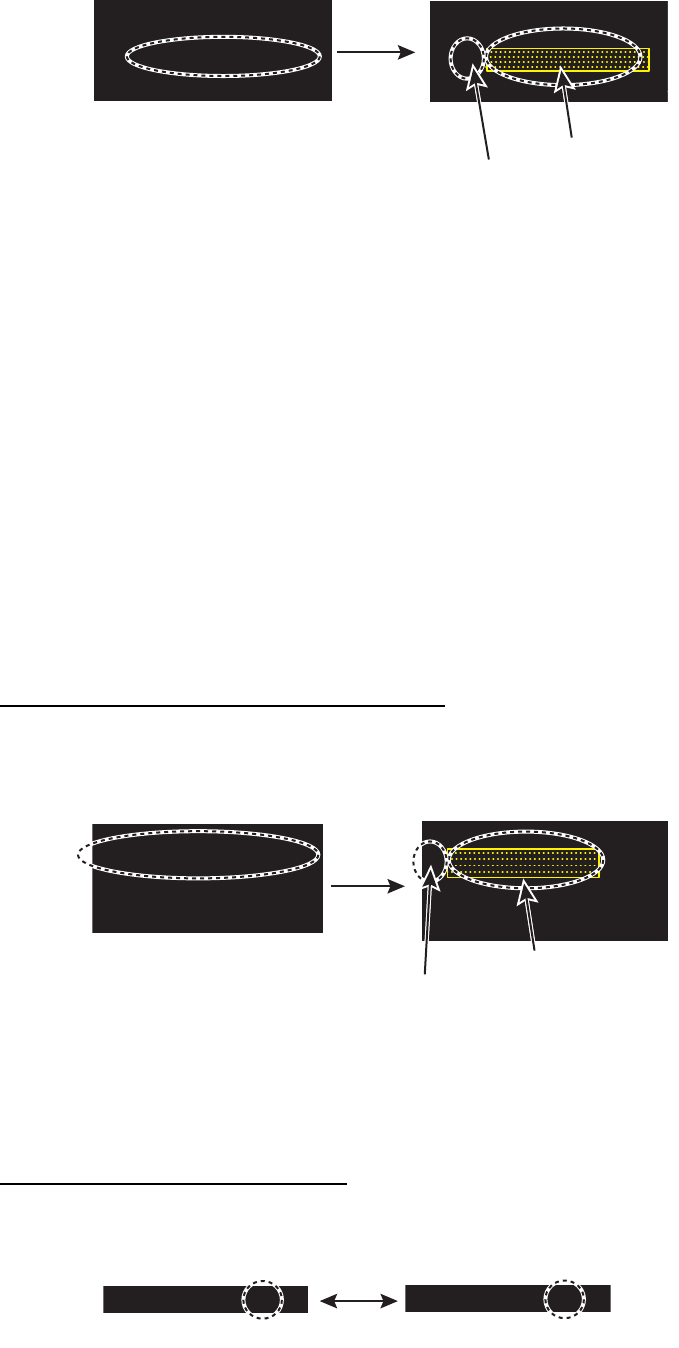
4. Click the new target position (A’). The
EBL is considered as the course of the
target.
Note: If the EBL passes through the
own ship’s position, the target ship is
on a collision course.
5. To return the EBL origin to the own
ship’s position, do the following procedure.
1) Right-click inside the display area to open [CURSOR MENU].
2) Click [EBL OFFSET].
3) Click the anywhere in the radar display area. The EBL origin moves to the own
ship’s position.
6. Right-click to quit the offset EBL.
000 010 020
030
040
050
060
070
080
090
100
110
120
130
140
150
160
170
180
190
200
210
220
230
240
250
260
270
280
290
300
310
320
330 340 350
A
EBL1
(a)
EBL origin
000 010 020
030
040
050
060
070
080
090
100
110
120
130
140
150
160
170
180
190
200
210
220
230
240
250
260
270
280
290
300
310
320
330 340 350
A’
Target’s course
EBL origin

1. OPERATION
1-26
1.20.3 Point of reference for origin point of offset EBL
The origin point of the offset EBL can be ground stabilized (geographically fixed), north
stabilized (true) or referenced to own ship’s heading (relative). This menu is available
in [SEA] mode only. However, the setting is applied in [RIVER] mode also.
1. In the [SEA] mode, open [MAIN MENU], click
[MARK] to show the [MARK] menu.
2. Click [EBL OFFSET BASE].
3. Click the origin point of the offset EBL.
[STAB GND]: Reference to latitude and longitude
of the origin position. Origin position is always
fixed regardless of your ship's movement.
[STAB HDG]: Reference to heading. The relationship between origin position and
own position is always kept.
[STAB NORTH]: Reference to North. The origin position changes with North
position.
4. Click outside the menu window to close the menu.
[MARK] menu ([SEA] mode)
[MARK]
1 BACK
2 OWN SHIP MARK
MIN/RECTANGLE/
PENTAGON
3 STERN MARK
OFF/ON
4 EBL OFFSET BASE
STAB GND/STAB HDG/
STAB NORTH
5 VRM SYNC OFFSET EBL
OFF/ON
1. OPERATION
1-27
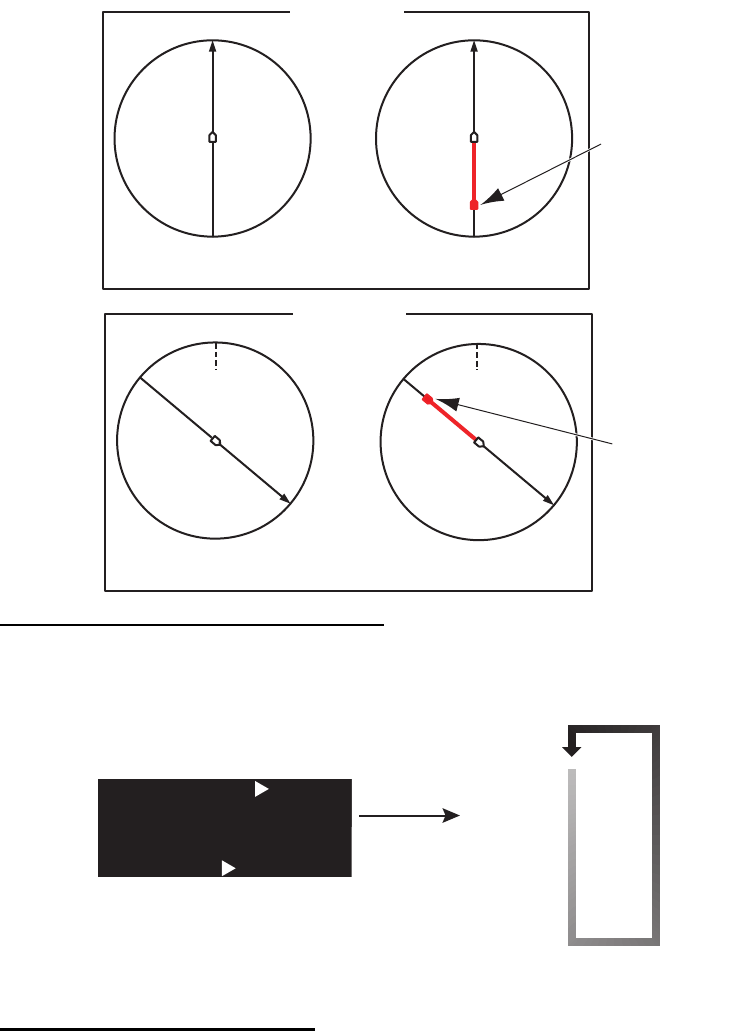
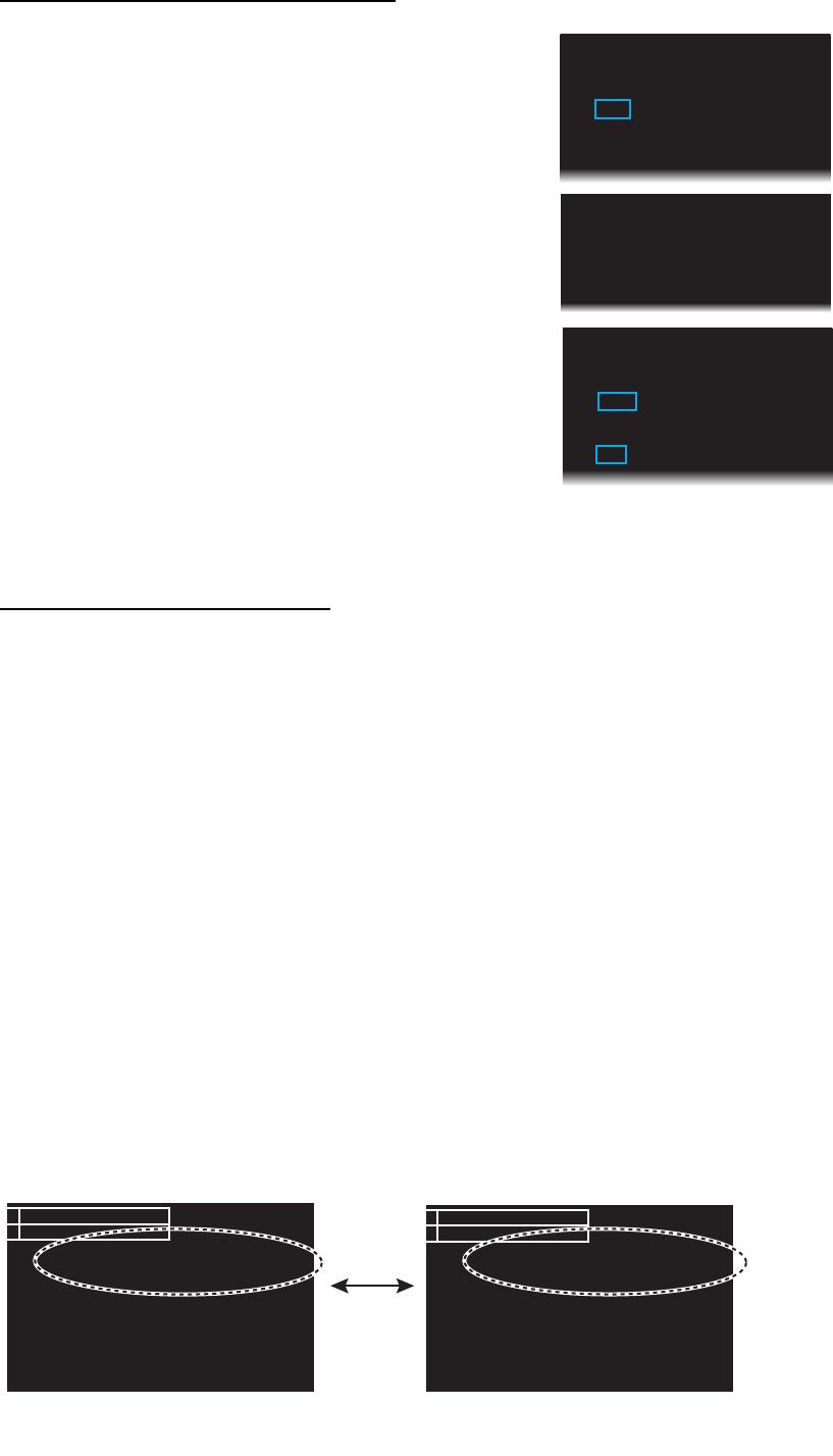
1.21 How to Off-center the Display
Own ship position, or sweep origin, can be displaced to expand the view field without
switching to a larger range scale. The sweep origin can be off-centered to the cursor
position, but not more than 60% of the range in use; if the cursor is set beyond 60%
of the range scale, the sweep origin will be off-centered to the point of 60% of the limit.
You can select the off-centering rate among, 20%, 40% or 60%.
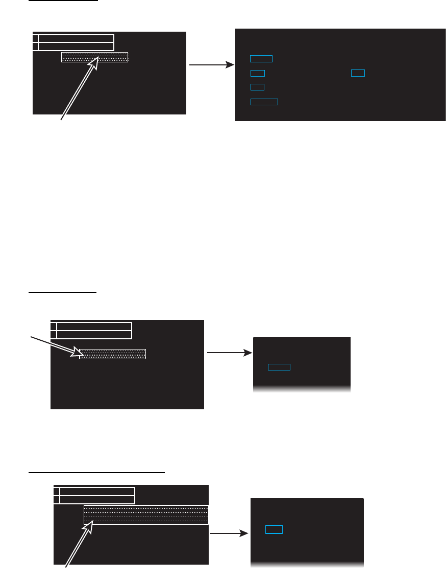
How to select the off-centering rate
1. Click the [OFFCENT] (Off-center) icon at the top left corner of the screen.
2. Click to switch the off-centering rate, [-20%], [-40%], [-60%] or [OFF].
How to off-center the display
1. Click inside the effective display area to open [CURSOR MENU].
2. Click [OFF CENTER].
3. Click the off-center point to be the center of the radar display.
4. Right-click to complete the off-center the display.
Heading
Stern
Off-center OFF Off-center ON
-60%
Head up
Off-centered
position
Off-centered
position
HeadingHeading
Off-center OFF Off-center ON
North up
SternStern
NorthNorth
SternStern
NorthNorth
-60% Off-centered
position
Off-centered
position
HeadingHeading
OFF CENT OFFOFF CENT OFF
OFFCENT -20%OFFCENT -20%
OFFCENT -40%OFFCENT -40%
OFFCENT -60%OFFCENT -60%
Switches the off-centering
HEAD
-
UP
STBY
OFFCENT
HDG
L
OFF
“OFFCENT” (Off-center) icon
Click
1. OPERATION
1-28
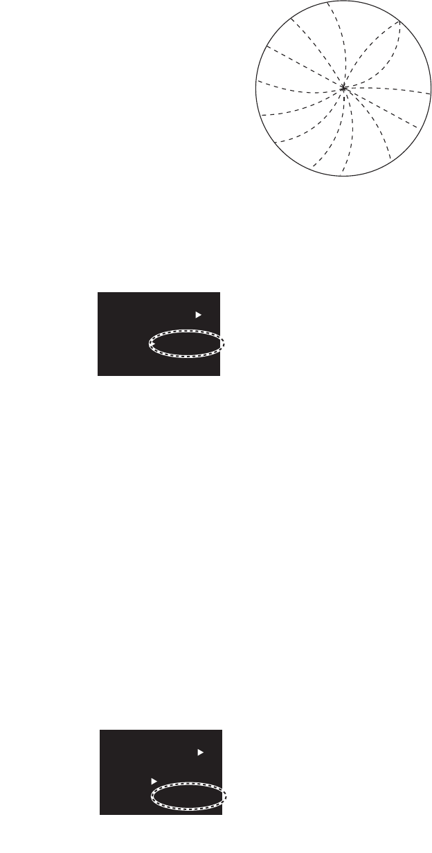
1.22 Interference Rejecter
The radar interference can occur when your ship is
near the radar of another ship that operates on the
same frequency band with your radar.
The interference shows on the screen as many
bright dots. The dots can be random or in the shape
of dotted lines that run from the center to the edge of
the display. You can identify the interference from
the normal echoes, because the interference does
not appear in the same location on the next antenna
rotation. When this feature is turned on, "IR 1", "IR
2" or "IR 3" appears at the bottom right corner on the
screen.
Click the IR (Interference Rejection) icon to switch the setting among [IR OFF], [IR 1],
[IR 2], [IR 3]. [IR 3] provides the highest degree of interference rejection.
Note: When there is no interference, turn off the interference rejecter so that you do
not miss small targets.
1.23 Echo Stretch
The echo stretch feature enlarges the targets in the range and bearing directions to
make the targets easier to see. This feature is available on any range. There are three
levels of echo stretch, [1], [2] and [3]. [3] enlarges the targets the most.
Note: The echo stretch magnifies the targets, sea and rain clutters, and radar
interference. Correctly adjust the sea clutter, rain clutter and radar interference before
you ac-tivate the echo stretch.
Click the [ES] (echo stretch) icon to switch the setting among [ES OFF], [ES 1], [ES 2]
and [ES 3].
“IR” (Interference rejection) icon
(at the bottom right corner on the screen)
FTC 1
IR 1
ES 2
EAV 3
TRAIL
2.50sec
00m03s
R
EL
ON
CUSTOM3-4
“ES” (Echo stretch) icon
(at the bottom right corner on the screen)
FTC 1
IR 1
ES 2
EAV 3
TRAIL
2.50sec
00m03s
R
EL
ON
CUSTOM3-4
1. OPERATION
1-29
1.24 Echo Averaging
To identify true target echoes from the sea clutter, echoes are averaged over
succes-sive picture frames. If an echo is solid and stable, the echo is shown in its
normal in-tensity. The brilliance of sea clutter is reduced to easily identify true targets
from the sea clutter.
Note 1: Do not use the echo average function under heavy pitching and rolling to
prevent loss of targets.
Note 2: This feature requires a heading signal and position data. When either signal
becomes lost, echo average is deactivated.
To correctly use the echo average function, first reduce the sea clutter properly. Leave
a little sea clutter on the screen so as not to erase weak targets. Then, do as follows:
Click the [EAV] (echo average) icon to switch the setting among [EAV OFF], [EAV 1],
[EAV 2], [EAV 3].
1.25 Target Trails
The trails of the radar targets can be shown simulated in afterglow to check target
movement. The target trails are selected for either relative or true. True trails require
a heading signal and position data.
1.25.1 How to start, stop the trails
Click the trail display icon to switch between [ON] and [OFF].
“EAV” (Echo average) icon
(at the bottom right corner on the screen)
FTC 1
IR 1
ES 2
EAV 3
TRAIL
2.50sec
00m03s
REL
ON
CUSTOM3-4
[ON]: Show trails [OFF]: Hide trails
(at the bottom right corner on the screen)
MAN TUNE
FTC
1
IR 1
ES 2
EAV 3
TRAIL
2.50sec
00m03s
REL
ON
ON
Trail display
icon
MAN TUNE
FTC 1
IR 1
ES 2
EAV 3
TRAIL
2.50sec
00m03s
REL
OFFOFF
Click
1. OPERATION
1-30
1.25.2 [TRAIL] menu
You can adjust the detail setting for trails on the [TRAIL] menu.
1. Right-click the [TRAIL] icon to show the [TRAIL] menu.
2. Click the required menu item.
3. Click an option for each menu.
4. Click outside the menu window to close the menu.
1.25.3 Trail mode
You can display the echo trails in true or relative motion.
True mode
The true trails show true target movements according to their over-the-ground speeds
and courses. The stationary targets do not show the trails. The true trails require a
heading signal and position data.
Relative mode
The relative trails show other ships’ movements relative to your ship. The stationary
targets also show the trails.
To select the trail mode, select the trail mode icon to switch the mode, [T-G], [T-S]
(True mode) or [REL] (Relative mode). For the ship speed mode ([T-G], [T-S]), see
"Speed menu" on page 1-52.
Note: [T-S] is available only when [SHIP SPEED] is set to [STW].
[TRAIL] icon
MAN TUNE
FTC 1
IR 1
ES 2
EAV 3
TRAIL
2.50sec
00m03s
REL
ON
1 BACK
2 TRAIL MODE
REL /TRUE
3 TRAIL LEVEL
1 /2/3/4
4 OS TRAIL
OFF/1/2
5 TRAIL COLOR OPTION
DEFAULT/USER
Right-
click
[TRAIL]
True trails Relative trails
Trail mode icon
[T-G]: True trail based on ground
[T-S]: True trail based on water
(at the bottom right corner on the screen)
INSTAL
AIS
FTC
IR
ES
EAV
TRAIL
2.50sec
00m03s
T-G
ON
CUSTOM3-
4
INSTAL
AIS
FTC
IR
ES
EAV
TRAIL
2.50sec
00m03s
RELREL
ON
CUSTOM3-4
Trail mode icon
[REL]: Relative mode
Click

1. OPERATION
1-31
1.25.4 Trail level
The level (intensity) of the afterglow that extends from radar targets may be selected
as below.
1. Right-click the trail icon to show the [TRAIL] menu.
2. Click [TRAIL LEVEL].
3. Select the trail level among 1 to 4.
The higher the number the greater the intensity of the afterglow.
4. Click outside the menu window to close the menu.
1.25.5 Trail time
Trail time, the trail plotting interval, is selected as follows. The elapsed time since the
start of the trail appears below the trail time.
To change the trail time, select the trail time icon. The setting of trail time is different
according to the operation mode.
• [RIVER] mode: 1.25 sec*, 2.5 sec, 5 sec
*: When the antenna rotation speed is 26 rpm, the [1.25 sec] is the same picture as
the [2.5 sec].
• [SEA] mode: 5 sec, 15 sec, 30 sec, 1 min, 3 min, 6 min
1.25.6 Own ship trail
You can show the trail of own ship as follows:
1. Right-click the [TRAIL] icon to show the [TRAIL] menu.
2. Click [OS TRAIL].
3. Click the option among [OFF], [1] or [2].
[OFF]: Hide the trail of own ship.
[1]: Show the trail of own ship.
[2]: Show the trail of own ship, but hide the trail of sea clutter near own ship.
4. Click outside the menu window to close the menu.
(at the bottom right corner on the screen)
AIS
FTC
IR
ES
EAV
TRAIL
00m03s
T-G
ON
CUSTOM3-
4
2.50sec
Trail time icon
Elapsed time since start of trail
1. OPERATION
1-32
1.25.7 Trail color modes
There are two color modes for the trail color, [DEFAULT] and [USER].
• [DEFAULT]: The trail color becomes the same color as the echo color.
• [USER]: The trail color is set on [TRAIL COLOR] in [BRILL MENU]. See "How to edit
[BRILL MENU]" on page 1-8
The trails always begin with the [DEFAULT] color mode. The [USER] color mode is
not saved after the power turns off.
1. Right-click the [TRAIL] icon to show the [TRAIL] menu.
2. Click [TRAIL COLOR OPTION].
3. Click the desired color mode, [DEFAULT] or [USER].
4. Click outside the menu window to close the menu.
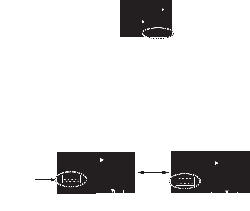
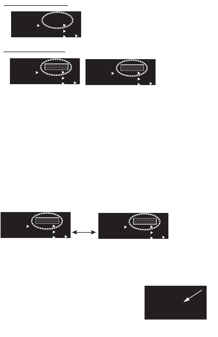
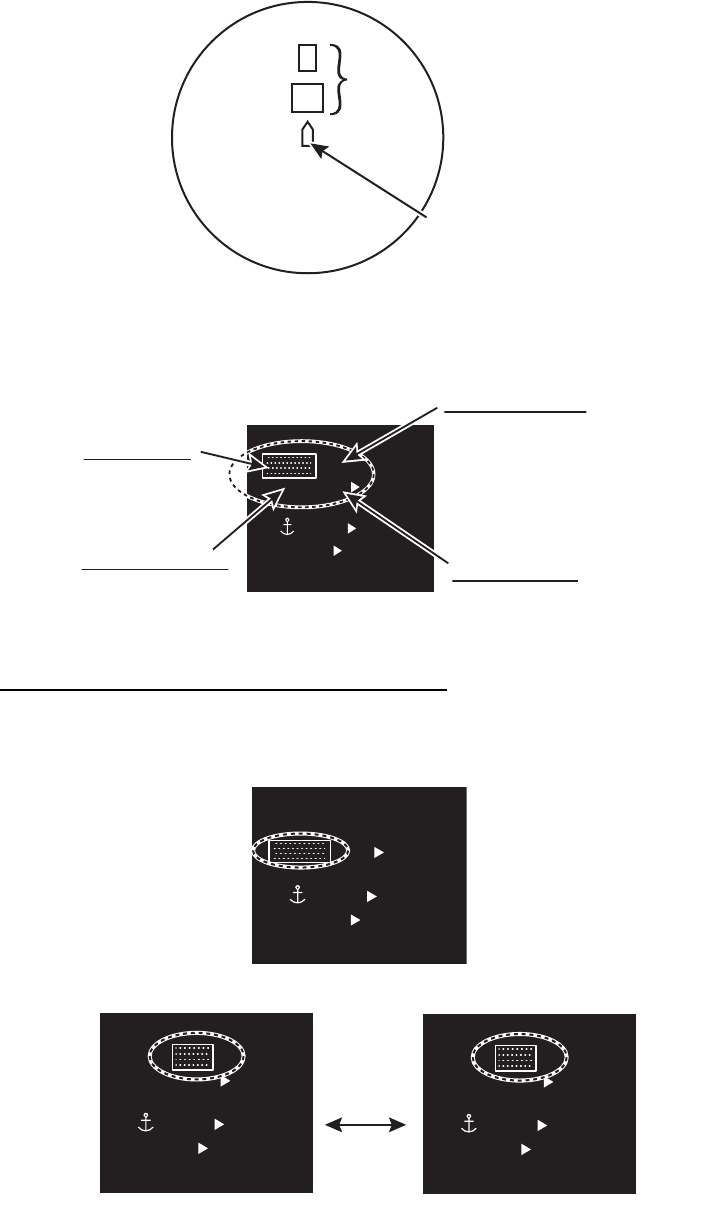
1.26 Target Alarm
The target alarm, available in the [SEA]
mode, serves to alert the navigator to
targets (ships, landmasses, etc.)
coming in/out a specific area, with
audio-visual alarms.
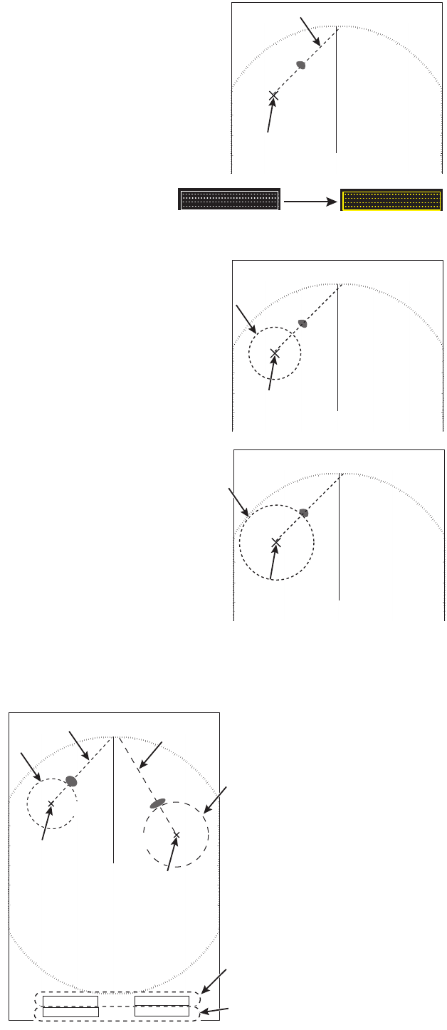
1.26.1 How to set a target alarm
The procedure below shows how to set a target alarm using the figure below as an
example.
1. Click the [ALR1] or [ALR2] icon. [SET] appears in the [ALR] icon.
2. Use the touch pad to select the point "A" on the radar screen then push the left
button.
· The alarm should not be relied upon
as the sole means for detecting
possible collision situations.
· [STC], [RAIN] and [GAIN] controls
should be properly adjusted to be sure
the alarm system does not overlook
target echoes.
NOTICE
ALR1: [SET]
AZ1
AZ2
ALR2
TT
ON
LIST
EBL1
1
2
>
EBL2
8
R
N
K
G
RN
ALR1
ALR1
AZ1
AZ2
ALR2
TT
ON
LIST
EBL1
1
2
>
EBL2
8
R
N
K
G
RN
ALR1
SET
ALR1
SET
(at the bottom left corner on the screen)
Click
1. OPERATION
1-33
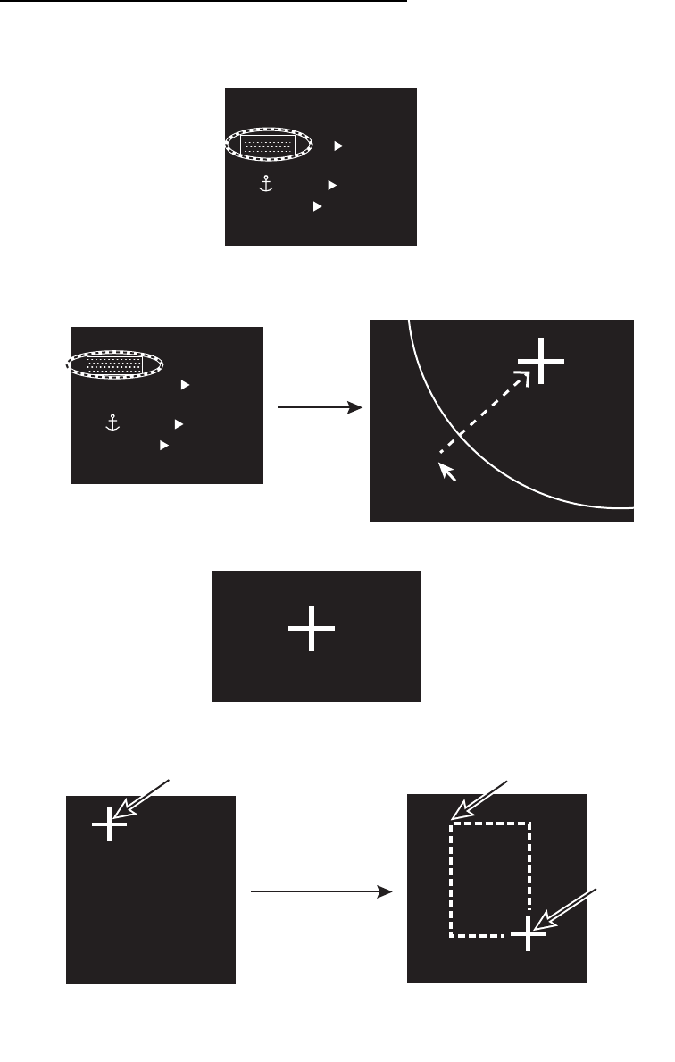
3. Use the touch pad to select the point "B" then push the left button. [IN] (or [OUT])
replaces [SET] in the [ALR] icon. The target alarm zone’s lines are shown in
dashed lines.
Note 1: If you wish to create a target alarm zone having a 360-degree coverage
around own ship, set point "B" in almost the same direction as point "A".
Note 2: Two target alarm zones may be set. Note however that the 2nd target alarm
zone is available only when the 1st target alarm zone is active.
1.26.2 How to select the alarm type
You can set the target alarm to activate
against targets entering or exiting the alarm
zone.
1. Open [MAIN MENU], click [ALARM] to
show the [ALARM] window.
2. Click [TARGET ALARM].
3. Click [ALR1 MODE] or [ALR2 MODE].
4. Click the alarm type, [IN] or [OUT].
5. Click outside the menu window to close
the menu.
Alarm type: [IN]
AZ1
AZ2
ALR2
TT
ON
LIST
EBL1 1
2
>
EBL2 8
R
N
K
G
RN
ALR1
IN
ALR1
IN
AZ1
AZ2
ALR2
TT
ON
LIST
EBL1 12
>
EBL2 8
RN
K
GRN
ALR1
OUT
ALR1
OUT
Alarm type: [OUT]
000 010 020
030
040
050
060
070
080
090
100
110
120
130
140
150
160
170
180
190
200
210
220
230
240
250
260
270
280
290
300
310
320
330 340 350 Target alarm zone
AB
X
X
Point A
X
X
X
X
Point B
Point B
Point B
Point A
Point A
Alarm zone examplesAlarm zone examples
Target “IN” alarm
Target “OUT”alarm
1 BACK
2 [TT•AIS]
3 [TARGET ALARM]
[ALARM]
1 BACK
2 ALR1 MODE
IN /OUT
3 ALR2 MODE
IN /OUT
4 LEVEL
1 /2/3/4
[TARGET ALARM]
1. OPERATION
1-34
1.26.3 How to select the target strength which triggers a target alarm
You can select the target strength which triggers the target alarm as follows.
1. Open [MAIN MENU], click [ALARM].
2. Click [TARGET ALARM].
3. Click [LEVEL].
4. Click the alarm echo strength level, [1] to [4]. [4] is the strongest.
5. Click outside the menu window to close the menu.
1.26.4 How to acknowledge the target alarm
A target in the target alarm zone produces both visual (flashing) and audible (beep)
alarms. To silence the audio alarm, press the left button or click the appropriate
[ALARM ACK] icon. This deactivates the audio alarm but does not stop flashing of the
offending target.
1.26.5 How to sleep a target alarm temporarily
You can sleep a target alarm zone when its use is not immediately needed. The alarm
zone remains on the screen, but any targets that enter (or exit) the alarm zone do not
trigger the audio and visual alarms.
1. Click the [ALR1] or [ALR2] icon until the icon reads "ALR1 ACK" or "ALR2 ACK".
2. To activate a sleeping target alarm zone, press the [ALR1] or [ALR2] icon until the
alarm indication changes to "ALM1 (or 2)_IN(or OUT)".
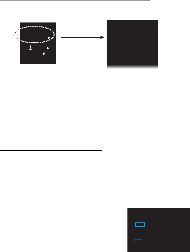
1.26.6 How to delete a target alarm
1. Click the appropriate [ALR] icon.
2. Press and hold down the left button until the [ALR] icon goes blank. The target
alarm is deleted from the screen.
Note: If both acquisition zones are active [ALR1] can not be deleted unless [ALR2] is
deleted.
1. OPERATION
1-35
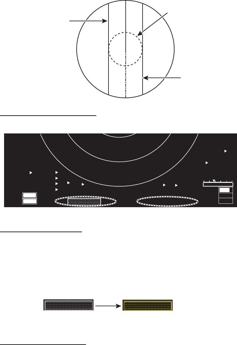
1.27 Nav Lines
There are two nav lines for port and starboard.
How to display the nav lines
Click the appropriate [NAV] icon at the bottom of the screen.
How to set the nav lines
Nav lines are set on both sides of own ship. The distance to port or starboard is
individually determined.
1. Click the appropriate [NAV] icon to display a nav line. If the nav line is already
displayed, go to step 2.
2. Click the [NAV] icon to activate the nav line. The icon turns yellow.
3. Click the position where you want to put the nav line in the radar display area.
How to turn off a nav line
Long press the appropriate [NAV] icon with the left button. The location of the line is
retained in the memory when the power is turned off.
NAV LINE
for port
NAV LINE
for starboard
VRM
MENU
BRL2-3
ECHO
B-IN
OUT
MONI
PANL
AZ1
AZ2
ALR1
ALR2
HL OFF
TT
ON
LIST
EBL1
123.4°
>
EBL2
82.9°
T
T
NM
GRN
BLK
D-GRN
50
15
AIS
FLT
VRM1
1.567
VRM2
0.160
NAV
0.160
NM
LIST
NM
NM
MAN
MAN
MAN
AUTO
TUNE
GAIN
STC
RAIN
75
FTC 1
IR 1
ES 2
EAV 3
TRAIL
2.50sec
00m03s
REL
ON
CUSTOM3-4
0
0
NAV
0.160
NAV
0.160
[NAV] icon for port [NAV] icon for starboard
82 9°
T
NAV
0.150NM
NAV
0.150NM
82 9°
T
NAV
0.150NM
NAV
0.150NM
Click
Highlighted yellow
1. OPERATION
1-36
1.28 Alarms, Error Messages
1.28.1 Alarm indication
When the alarm is generated, the [ALARM] icon flashes (in red) and the audio alarm
sounds.
How to acknowledge the alarm
Click the [ALARM ACK] icon to acknowledge the alarm and silence the audio alarm.
The [ALARM] icon continues flash until the cause of the alarm is cleared.
Icon indication Status Meaning
No alarm.
Red character and
flashing.
An alarm is generated.
Red character and
not flashing.
All generating alarms are acknowledged.
Or all alarms are not in alarm status but not
acknowledged.
RIVER
ROT
RUDDER
1.2/ 0.5
km
HEAD-UP
STBY
OFFCENT
HDG 123.4°
ALARM
ALARM
ACK
L
OFF
(at the top left corner
on the screen)
[ALARM ACK] icon
[ALARM] icon
ALARM
ALARM
ALARM

1. OPERATION
1-37
1.28.2 Alarm description
Alarm description
Alarm type Alarm message Meaning
COLLISION
ALARM
TT DANGEROUS CPA and TCPA of a TT is within a preset limit.
AIS DANGEROUS CPA and TCPA of an AIS target is within a preset
limit.
DEPTH LIMIT The depth measured by the depth sensor(s) is
within a preset limit.
TARGET ALARM A target has entered (or exited) a target alarm zone.
SYSTEM
ERROR
NO VIDEO Loss of video signal.
NO AZIMUTH Loss of azimuth signal.
NO HEADLINE Loss of heading signal.
CONTROL HEAD COMMUNI-
CATION ERROR
No communication between control unit and UIP
(Control unit may not be connected.)
CPU TEMPERATURE CPU has overheated.
TUNE CONTROL Radar tuning problem.
FAN MOTOR Fan motor has stopped.
SENSOR
ERROR
NO GYRO Loss of gyrocompass (heading) signal.
NO LOG Loss of log (speed) signal.
NO EPFS No position data.
NO ECHO SOUNDER No depth data from echo sounder.
NO WIND SENSOR No wind data.
SPEED No VTG signal.
ROT Abnormal ROT signal.
EPFS FRONT (AFT) ERROR GPS sensor is not stopped.
ECHO SOUNDER FRONT
(AFT) ERROR
Depth data at front or aft sensor is not received.
AIS ALARM NO CPA/TCPA FOR AIS No COG or SOG for AIS.
AIS RECEIVE ERROR No VRM or VDO sentences for 30 seconds (or the
AIS function).
AIS ACTIVATE 100% The maximum number of AIS targets has been
activated.
OTHER
WARNING
TUNE INITIALIZE Tuning is being initialized.
RD DATA ERROR Data of SD card is corrupted.
WR DATA ERROR Data of SD card was not written correctly.
SERVICE ENTRY Service menu enabled (by serviceman).
1. OPERATION
1-38
1.28.3 Alarm summary
When an alarm is generated the color of the [ALARM] icon (top of display) turns red.
You can see what alarms have been generated in the [ALARM SUMMARY] menu.
1. Right-click the [ALARM] icon to show the [ALARM] menu.
2. Click the [ALARM SUMMARY]. Active alarms are shown in red.
Red, flashing: Alarms generated and not acknowledged.
Red, not flashing: Alarms generated and acknowledged.
1.28.4 Alarm list/history
The alarm list displays the names of violated alarms, including the time and date
violated. Unacknowledged alarms are displayed first in the list (in red text), latest to
earliest.
Alarm indication Meaning Alarm indication Meaning
[TRIG] No trigger [GYRO] No gyro
[VIDEO] No video [LOG] No log
[AZ] No azimuth [EPFS] No EPFS
[HL] No heading [ROT] No ROT (Rate of turn)
[ALARM]
1 BACK
2 ALARM SUMMARY
3 ALARM LIST/HISTORY
RIVER
ROT
RUDDER
1.2/ 0.2
km
HEAD-UP
STBY
OFFCENT
HDG 123.4°
ALARM
ALARM
ACK
S
OFF
Right-
click
TRIG VIDEO AZ HL
GYRO LOG EPFS ROT
(at the bottom left corner on the screen)
[ALARM LIST] 1/1
ITEM TYPE DATE/TIME
ROT SENSOR ERROR
00:00:000000/00/00
AIS RECEIVE ERROR AIS WARNING 00:00:000000/00/00
[ALARM HISTORY] 1/1
ITEM TYPE DATE/TIME
ROT SENSOR ERROR
00:00:000000/00/00
AIS RECEIVE ERROR AIS WARNING 00:00:000000/00/00
Click [SW] icon to switch between
alarm list and history.
[SW] icon
1. OPERATION
1-39
1.28.5 Depth alarm
The depth alarm warns you when the depth is shallower than the preset depth value.
When you change the depth, follow the steps below.
1. Open [MAIN MENU], click [NAV DATA].
2. Click [DEPTH].
3. Click [DEPTH ALARM VALUE] then set the value by rotating the setting knob. The
setting range is 0.00 to 9.99 m.
Note: When the setting is 0.00, the alarm is not generated.
4. Click outside the menu window to close the menu.
1.28.6 ROT alarm
The ROT graph displays ship's rate of turn (degrees/min) using the ROT signal fed
from an ROT sensor. If the ROT data is lost, the indication "ROT ALARM" appears in
[ALARM LIST] and the audio alarm sounds. To acknowledge loss of the ROT signal,
click the [ALARM ACK] icon.
1.29 Docking Mode
The docking mode provides;
• Depth at the fore and aft
• Speed and movement at the fore, midpoint and aft
• Wind speed and direction
Front 10.4m
Aft 13.7m
Front 10.4m
Aft 13.7m
10.4
m/s
10.4
m/s
3.5
km/h
3.5
km/h
3.5
km/h
3.5
km/h
3.5
km/h
3.5
km/h
Wind icon
(Wind speed and
direction)
Dual depth icon
(Depth at fore and aft)
Speed icon
(Speed and
movement at fore,
midpoint and aft)
1. OPERATION
1-40
1.29.1 How to activate the docking mode
The docking mode can be shown in TX mode.
1. Open [MAIN MENU], click [DISPLAY].
2. Click [DOCKING MODE].
3. Click [ON] to display the docking icon at the minimum range among the available
ranges. The docking icon [DOCK] is shown at the bottom left corner on the screen.
4. Click outside the menu window to close the menu.
1.29.2 How to show or hide the docking information display
You can show the docking information automatically at the following ranges. When
you show the docking information, the radar display is shown at the minimum range.
• [RIVER] mode: 0.125 SM to 0.25 SM
• [SEA] mode: 0.125 NM to 0.25 NM, 0.125 SM to 0.25 SM, 0.125 km to 0.5 km,
0.125 kyd to 0.5 kyd
The docking information appears at the top of the radar screen. You can show or hide
the information with the [DOCK] icon as shown below.
1.29.3 Wind speed and direction
Wind speed and direction are provided with the
docking information display. Relative speed is
indicated digitally and direction is shown with an arrow.
MENU
BRL2-3
ECHO
BIN
AZ1
AZ2
ALR1
TT
ON L
GRN
BLK
DOCK ON
DOCK ON
MENU
BRL2-3
ECHO
BIN
AZ1
AZ2
ALR1
TT
ON L
GRN
BLK
DOCKING MODE: [OFF]
DOCKING MODE: [ON]
MENU
BRL2-3
ECHO
BIN
AZ1
AZ2
ALR1
TT
ON L
GRN
BLK
DOCK OFF
DOCK OFF
[DOCK ON]
Docking information is shown.
[DOCK OFF]
Docking information is hidden.
Docking icon is hidden.
MENU
BRL2-3
ECHO
BIN
AZ1
AZ2
ALR1
TT
ON
L
GRN
BLK
DOCK ON
DOCK ON
(at the bottom right corner on the screen)
Docking icon: [ON]
Docking icon: [ON]
MENU
BRL2-3
ECHO
BIN
AZ1
AZ2
ALR1
TT
ON
L
GRN
BLK
DOCK OFF
DOCK OFF
Docking icon: [OFF]
Docking icon: [OFF]
Click
The wind of 10.4 m/s
coming from 45° (relative)
10.4 m/s
1. OPERATION
1-41
1.29.4 Depth data
Depth at the fore and aft are shown with the docking information display. Requires fore
and aft depth data.
Note: The dual depth required two transducers.
Depth data example
How to select the depth sensor
1. Open [MAIN MENU], click [NAV DATA].
2. Click [DEPTH].
3. Click [DUAL SENSOR].
4. Click the required sensor.
[BOTH]: Both fore and aft depths.
[FRONT]: Fore depth only.
[AFT]: Aft depth only.
Depth indications and orientation mode
The stern mode shows aft depth on top.
Depth display format
Depth can be shown digitally or in graph form.
1. Open [MAIN MENU], click [NAV DATA].
2. Click [DEPTH].
3. Click [GRAPH TYPE].
4. Click a required option.
[NUMERICAL]: Displays the
depth data digitally.
[GRAPHICAL]: Displays the
depth data graphically.
Depth at fore Front 10.4 m
Aft 13.7 m
Graph type: [NUMERICAL] Graph type: [GRAPHICAL]
Depth at aft
0
4
8
12
16
20m
3 2 1 min
Head up mode Stern up mode
Front 123.5 ft
Aft 109.8 ft
Aft 109.8 ft
Front 123.5 ft
[DEPTH]
1 BACK
2 GRAPH TYPE
NUMERICAL /GRAPHICAL
3 DUAL SENSOR
BOTH /FRONT/AFT
4 [DEPTH SCALE]
5 TIME SCALE
15sec/30sec /1min/3min
6 DEPTH ALARM VALUE
5. 00m
1. OPERATION
1-42
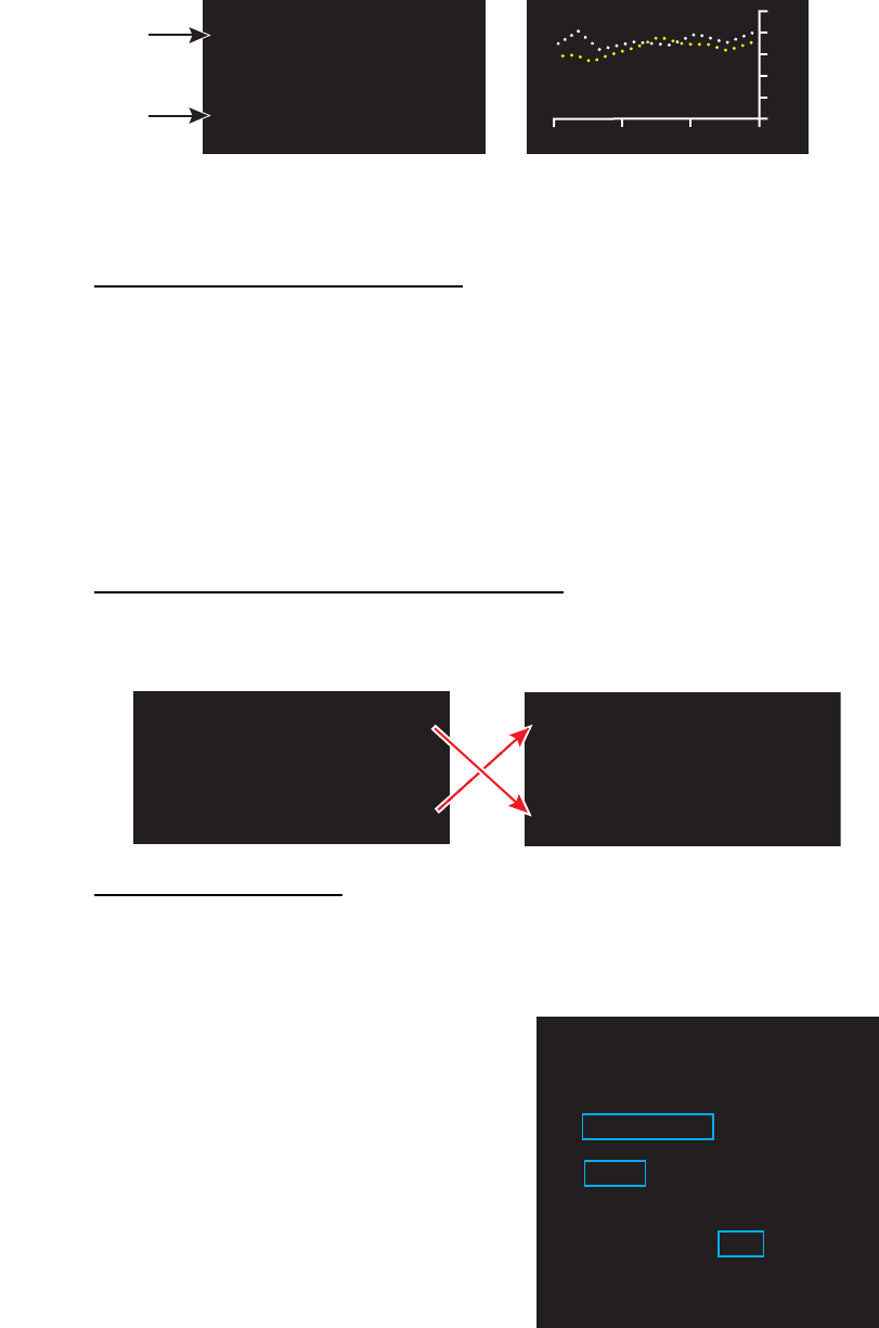
1.29.5 Depth graph
You can see the depth data in graph format by setting [GRAPH TYPE] to
[GRAPHICAL] (see step 3 in "Depth display format" on page 1-41). The depth graph
shows the depth history with dots, not a line.
Depth graph example
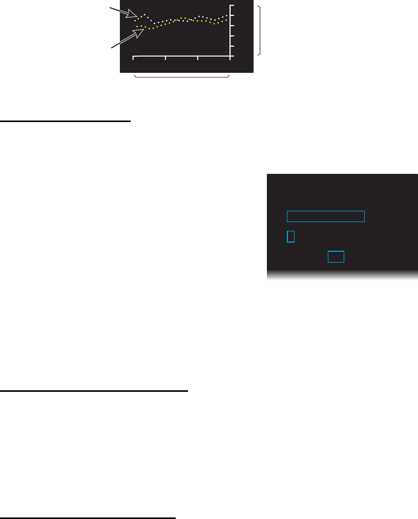
How to set depth graph
1. Open [MAIN MENU], click [NAV DATA].
2. Click [DEPTH].
3. Click [DEPTH SCALE].
4. Click [SCALE TYPE].
5. Click the scale to use, [RIVER] or [SEA].
6. Click an appropriate option for the scale
selected at step 5.
[RIVER]: 4, 10, 40
[SEA]: 10, 20, 50, 100, 200, 500
7. Click [BACK] to go back the [DEPTH] window.
8. Click [TIME SCALE].
9. Click the time scale (horizontal axis) for the depth graph, among 15 sec, 30 sec,
1 min and 3 min.
10. Click outside the menu window to close the menu.
How to select the depth sensor(s)
The depth graph can show depth data from the front and/or aft. The front data is shown
in white; aft data is yellow. See "Depth menu" on page 1-52 to select the depth sensor.
1.29.6 Speed and movement indications
The docking mode provides speed and movement indications at the fore, midpoint and
aft. Require GPS sensor or satellite compass.
How to select the speed sensor
1. Open [MAIN MENU], click [NAV DATA].
2. Click [PREDICTION].
3. Click [OWN SHIP POSITION].
4. Click a sensor.
[DUAL-GPS]: Display fore-aft and port-starboard speeds, fed from GPS
navigator.
[SC]: The speed data from satellite compass.
5. Click outside the menu window to close the menu.
0
4
8
12
16
20m
3 2 1 min
Depth
Past time
Depth at front
sensor (white)
Depth at aft
sensor (yellow)
[DEPTH SCALE]
1 BACK
2 SCALE TYPE
RIVER/SEA
3 RIVER
4/10/40
4 SEA
10/20/50/100/200/500
1. OPERATION
1-43
Speed and movement indications and orientation mode
The stern mode shows aft speed on top.
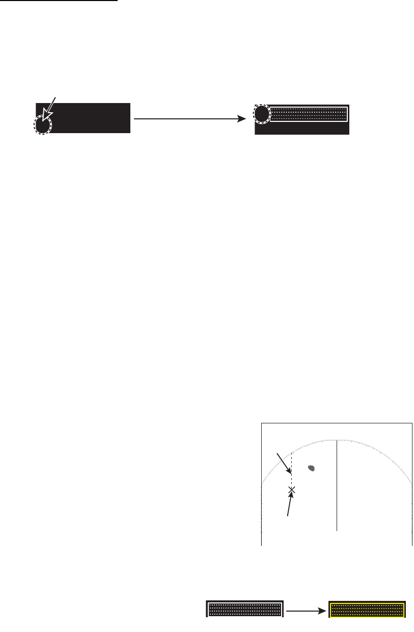
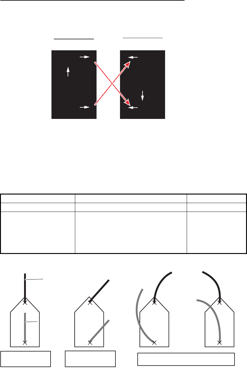
1.30 How to Predict Own Ship’s Position
You can predict ship’s position in the vector time selected. This function requires two
GPS sensors and heading data. Some settings for own ship vector are required as
follows:
Menu items Settings Reference
[OWN SHIP VECTOR] [COURSE] paragraph 1.37.4
[VECTOR TIME] Set a time between 30 sec ond s t o
6 minutes.
Note: The shorter the time the more
accurate the prediction. [30sec] or
[1min] is recommended.
paragraph 2.10.2
Head up mode Stern up mode
FRONT AFT
AFT FRONT
7.4
kn
5.7
kn
3.5
kn
3.5
kn
5.7
kn
7.4
kn
GPS-1GPS-1
GPS-2GPS-2
GPS-1GPS-1
GPS-2GPS-2
GPS-1GPS-1
GPS-2GPS-2
GPS-1GPS-1
GPS-2GPS-2
Prediction line
from GPS-1
Prediction line
from GPS-1
Prediction line
from GPS-2
Prediction line
from GPS-2
Ship’s is running
straight ahead
Ship’s course is
approx. 45°. Ship’s predicted position in a turn

1. OPERATION
1-44
1.31 How to Program Function Keys (F1 and F2)
You can program function keys (F1 and F2) to provide one-touch access to a required
function. To activate a function, press the applicable function key, F1 or F2. The
default program for the F1 and F2 keys are [ORIENTATION MODE] and [DOCKING]
respectively.
How to program a function key
1. Open [MAIN MENU], click [CONFIGURATION].
2. Click [FUNCTION KEY].
3. Click the function key ([F1] or [F2]) to program.
4. Click the appropriate program category. The options for each category are shown
on the below and on the next page. Some items have multilevel options.
• Programs available in the [ECHO] menu
• Programs available in the [STD KEY] menu
• Programs available in the [TT.AIS] menu
[F1]
1 BACK
2 [ECHO]
3 [STD KEY]
4 [TT•AIS]
5 [OPERATION]
6 [BRILL]
7 [CUSTOM]
1 BACK
2 CUSTOM-MENU/
FTC/
IR/
ES/
EAV/
AUTO-GAIN/
AUTO-STC/
AUTO-RAIN/
TUNE SELECT/
TRAIL DISPLAY/
TRAIL TIME/
TRAIL T/R/
WIPER
[F1-ECHO]
1 BACK
2 ALARM ACK/
EBL OFFSET/
OPERATION MODE/
ORIENTATION-MODE/
CU-TM RESET/**
VECTOR TIME/
VECTOR MODE/
TT-LIST/**
AIS-LIST/
BRILL-MENU/
MARK/*
CAPTURE
[F1-STD KEY]
*: [RIVER] mode only
**: [SEA] mode only
[F1-TT•AIS]
1 BACK
2 TT-DISP/**
AIS-DISP/
PAST POSN INTERVAL/
REF MARK/**
CPA LIMIT/
CPA/
TCPA/
AZ1/**
AZ2/**
AIS SCALED SYMBOL
**: [SEA] mode only

1. OPERATION
1-45
• Programs available in the [OPERATION] menu
• Programs available in the [BRILL] menu
• The available function to program in the [CUSTOM] menu
5. Click outside the menu window to close the menu.
1 BACK
2 ECHO COLOR/
MONITOR BRILL/
PANEL DIMMER/
TRANSPARENCY/
ALARM1/**
ALARM2/**
ECHO AREA/**
DOCKING/
MARK/LINE-ON/*
BARGE-ON/*
MAP ALIGN/*
MARK/LINE ALL DELETE/*
BARGE ALL DELETE*
[F1-OPERATION]
*: [RIVER] mode only
**: [SEA] mode only
1 BACK
2 USER NAME 1
BRL1-1/
BRL1-2/
BRL1-3/
BRL1-4
3 USER NAME 2
BRL2-1/
BRL2-2/
BRL2-3/
BRL2-4
4 USER NAME 3
BRL3-1/
BRL3-2/
BRL3-3/
BRL3-4
5 USER NAME 4
BRL4-1/
BRL4-2/
BRL4-3/
BRL4-4
[F1-BRILL]
1 BACK
2 USER NAME 1
CUSTOM1-1/
CUSTOM1-2/
CUSTOM1-3/
CUSTOM1-4
3 USER NAME 2
CUSTOM2-1/
CUSTOM2-2/
CUSTOM2-3/
CUSTOM2-4
4 USER NAME 3
CUSTOM3-1/
CUSTOM3-2/
CUSTOM3-3/
CUSTOM3-4
5 USER NAME 4
CUSTOM4-1/
CUSTOM4-2/
CUSTOM4-3/
CUSTOM4-4
[F1-CUSTOM]
1. OPERATION
1-46
1.32 Markers
1.32.1 [MARK] menu
The [MARK] menu lets you:
• Change the configuration of the own ship mark
• Show or hide the stern mark
• Set the reference point for the offset EBL
• Activate VRM with the offset EBL
1. Open [MAIN MENU], click [MARK].
2. Click the item.
3. Click the required option.
4. Click outside the menu window to close the menu.
1.32.2 Heading line
The heading line indicates the ship's heading in all orientation modes. The heading
line is a line from the own ship position to the outer edge of the radar display area and
appears at zero degrees on the bearing scale in head-up mode. It changes its
orientation depending on the ship orientation in north-up and true motion modes.
How to hide the heading line temporarily
To temporarily hide the heading line to look at targets existing dead ahead of own ship,
press the HL OFF key on the control unit. Release the key to redisplay the heading
line, etc.
[OWN SHIP MARK] Select the shape of own ship mark.
[STERN MARK] Select on/off the stern mark display.
[EBL OFFSET BASE]
([SEA] mode only)
See paragraph 1.20.3.
[VRM SYNC OFFSET EBL]
([SEA] mode only)
Turn this feature on to automatically activate applicable
VRM when using an offset EBL.
[MARK] menu ([SEA] mode)
[MARK] menu ([RIVER] mode)
[MARK]
1 BACK
2 OWN SHIP MARK
MIN/RECTANGLE/
PENTAGON
3 STERN MARK
OFF/ON
[MARK]
1 BACK
2 OWN SHIP MARK
MIN/RECTANGLE/
PENTAGON
3 STERN MARK
OFF/ON
4 EBL OFFSET BASE
STAB GND/STAB HDG/
STAB NORTH
5 VRM SYNC OFFSET EBL
OFF/ON
1. OPERATION
1-47
1.32.3 Stern mark
The stern marker, which is a dot-and-dash line, appears opposite to the heading line.
To display or erase this marker do the following:
1. Open the [MARK] menu, click [STERN MARK].
2. Click [OFF] or [ON] as appropriate.
3. Click outside the menu window to close the menu.
1.32.4 North mark
The north mark appears as a short dashed line. The north mark moves around the
bearing scale in accordance with the compass signal in the head-up, head-up (TB) or
stern-up mode.
Note: It is not possible to delete the north mark. The north mark is always indicated
while a heading sensor is input.
1.32.5 Own ship mark
The own ship symbol marks own position on the display. The symbol is selected from
the [MARK] menu.
1. Open the [MARK] menu, click [OWN SHIP MARK].
2. Click the own ship mark shape to use.
3. Click outside the menu window to close the menu.
North markNorth mark
Head-up mode,
Head-up (TB) mode North-up mode
[MIN] [RECTANGLE] [PENTAGON]
Own ship Own ship Own ship
1. OPERATION
1-48
1.32.6 Barge mark
You may mark the locations of barges on the display with barge mark. This function is
available for [RIVER] mode only.
The barge mark is a set of rectangles drawn to indicate the outline of barges. You can
create a max. total of 10 barge marks. There are four icons for the barge mark as
follows:
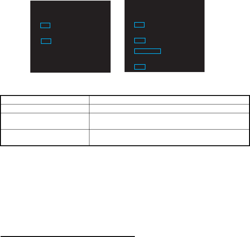
How to show a barge mark on the screen
1. Click the barge number icon then rotate the setting knob to select the barge
number (1 to 10).
2. Click the barge display icon to show or hide.
Own ship
Barge markBarge mark
(at the bottom left corner on the screen)
MENU
ON
2WHT
ON
CYA DOCK OF
F
BRL2-3
ECHO
BIN
GRN
BLK
MARK
MARK
BARGE
BARGE
Barge number icon
(1 to 10) Barge color icon
(GRN, BLU, YEL, CYA, MAG, WHT)
Barge display icon
[ON]: Shows the barge mark(s)
on the [BARGE] icon.
[OFF]: Hides the barge mark(s)
shown on the [BARGE]
icon.
[BARGE] icon
MENU
BARGE ON
WHT
ON
CYA DOCK OF
F
BRL2-3
ECHO
BIN
GRN
BLK
MARK
MARK
2
2
Barge display icon: [ON] Barge display icon: [OFF]
MENU
BARGE
2WHT
ON
CYA DOCK OF
F
BRL2-3
ECHO
BIN
GRN
BLK
MARK
MARK
ON
ON
MENU
BARGE
2WHT
ON
CYA DOCK OF
F
BRL2-3
ECHO
BIN
GRN
BLK
MARK
MARK
OFFOFF
Click
1. OPERATION
1-49
How to create a barge mark on the screen
1. Click the barge number icon then rotate the setting knob to select the barge
number (1 to 10).
2. Click the [BARGE] icon to enable creation of the barge mark. The cursor shape
changes from an arrow to a cross mark.
3. Click the start point (X-axis and Y-axis) of the barge mark.
4. Select the 2nd point of the barge mark. As you drag the cursor, the width of the
X-axis and Y-axis are displayed and the barge mark is drawn with a dashed line.
5. Click the 2nd point to complete the barge mark. The mark changes to the
rectangle with the solid line.
MENU
BARGE ON
WHT
ON
CYA DOCK OFF
BRL2-3
ECHO
BIN
GRN
BLK
MARKMARK
22
MENU
ON
WHT
ON
CYA DOCK OF
F
BRL2-3
ECHO
BIN
GRN
BLK
MARK
MARK
2
2
BARGE
BARGE
The arrow changes
to the cross mark.
The arrow changes
to the cross mark.
Click
X= 0ft
Y= 0ft
X= 0ft
Y= 0ft
X= 5ft
Y= 20ft
1st point of the barge mark
(Barge mark size:
wide(X)= 0 ft, length (Y)= 0 ft)
Click the 2nd point.
The barge mark is completed.
(Barge mark size:
wide(X)= 5 ft, length (Y)= 20 ft)
1st point
2nd point
1st point
1. OPERATION
1-50
How to create a barge mark from the [BARGE ICON] menu
1. Right-click the any icon of barge mark to show the [BARGE NUMBER] menu.
2. Click [POSITION BY X].
3. Set start point in X-axis for drawing the barge mark with the left and right buttons.
4. Click [POSITION BY Y].
5. Set start point in Y-axis for drawing the barge mark with the left and right buttons.
6. Click [SIZE BY X].
7. Set the width of the barge mark with the left and right buttons.
8. Click [SIZE BY Y].
9. Set the length of the barge mark with the left and right buttons.
How to edit a barge mark on the screen
If the barge mark is currently displayed, go to step 3.
1. Select the barge number icon to show the barge number to edit. Also, you can se-
lect the barge mark directly by putting the cursor on the line of the barge mark (In
this case, go to step 3).
2. Set [ON] at the display icon to display the barge mark to edit. The selected barge
mark turns red.
3. Right-click the barge mark.
4. Click the required action and its option.
[COLOR]: Change the color of the barge mark.
[MOVE]: Drag and drop the barge mark by the
touch pad.
[DELETE]: Delete the barge mark.
1 BACK
2 POSITION BY X
X = +000ft
3 POSITION BY Y
Y = +000ft
4 SIZE BY X
X = 010ft
5 SIZE BY Y
Y = 020ft
MENU
ON
2WHT
ON
CYA D
O
BRL2-3
ECHO
BIN
GRN
BLK
MARK
MARK
BARGE
BARGE
- BARGE icon
- Barge number icon
- Barge display icon
- Barge color icon
Click any icon
[BARGE NUMBER 2]
1 BACK
2 COLOR
GRN/BLU/YEL/CYA/
MAG/WHT
3 MOVE
4 DELETE
NO/YES
[BARGE]
1. OPERATION
1-51
How to delete barge marks by color
1. Open [MAIN MENU], click [RADAR MAP].
2. Click [DATA DELETE].
3. Click [BARGE DELETE].
4. Click [COLOR].
5. Click the barge color to delete.
6. Click outside the menu window to close the menu.
How to delete all barge marks
1. Do the procedure from step 1 to step 3 in "How to delete barge marks by color" on
page 1-51.
2. Click [BARGE ALL DELETE].
3. Click [YES].
4. Click outside the menu window to close the menu.
1.33 NAV Data
The following navigation data may be set up on the menu.
1.33.1 How to show ship’s position or speed and depth alternately
At the top right corner on the screen, click the icon below to switch between “Speed
and Depth” and “Own ship position”.
- Speed - Depth - Own ship position
- Time to the cursor position - Wind - Date
- ROT graph - Rudder graph - AUTOPILOT graph
1 BACK
2 MAP ALIGN
OFF/ON
3 [MARK/LINE INFO]
4 [DATA DELETE]
[RADAR MAP]
1 BACK
2 [MARK/LINE DELETE]
3 [BARGE DELETE]
[DATA DELETE]
1 BACK
2 COLOR
GRN/BLU/YEL/CYA/
MAG/WHT
3 BARGE ALL DELETE
NO/YES
[BARGE DELETE]
“speed” and “depth” “latitude and longitude”
(own ship position)
Click
CAPT
±300 °/min
±180 °
SPD BT GPS-F►
DPT AFT ►
CURSOR TTG 18m20s
01-sep-2012
►
44. 6km/h
3. 2m
UTC 12:34
6.34NM / 300.3°R
CAPT
±300 °/min
±180 °
OS POSN N
CURSOR TTG 18m20s
2. 4m/s
0° 00. 219°
WIND
E0° 00. 397°
►
6.34NM / 300.3°R
1. OPERATION
1-52
Speed menu
Right-click the speed icon ([SPD]) to show [SPEED MENU].
Depth menu
Right-click the depth icon ([DPT]) to show [DEPTH MENU].
Click [SELECT DUAL SENSOR]. Then, click the depth sensor to use to show depth
data, [FRONT] or [AFT].
Own ship position menu
Right-click the own ship position icon to show [OWN SHIP POSITION MENU].
• [SELECT DUAL SENSOR]: Select the sensor data, [FRONT] or [AFT].
• [SHIP SPEED]: Select the speed indication format, [SOG] (speed over ground) or
[STW] (speed towards water).
• [GROUND SPEED SOURCE]: Select the input source for SOG.
• [WATER SPEED SOURCE]: Select the input source for STW.
• [MANUAL SPEED]: Input the speed manually.
• [SET DRIFT]: Turn on or off drift.
• [SET CURRENT CRS]: Set the direction of the tide.
• [SET CURRENT SPD]: Set the speed of the tide.
• [NAV AID]: Click the source of ship position data, [GPS] or [DEAD RECKON] (dead
reckoning).
• [MANUAL L/L]: For [DEAD RECKON], enter the latitude and longitude, using the
software keyboard.
Right-
click
1 BACK
2 SELECT DUAL SENSOR
FRONT/AFT
3 SHIP SPEED
SOG/STW
4 GROUND SPEED SOURCE
GPS/REF/LOG(BT)
5 WATER SPEED SOURCE
LOG(WT)/MANUAL
6 MANUAL SPEED
0. 0kn
7 SET DRIFT
OFF/ON
8 SET CURRENT CRS
0. 0deg
9 SET CURRENT SPD
0. 0kn
CAPT
±300 °/min
±180 °
DPT AFT
►
CURSOR TTG 18m20s
01-sep-2012
►
44. 6km/h
3. 2m
SPD BT GPS-F
►
SPD BT GPS-F
►
6.34NM / 300.3°R
UTC 12:34
Speed icon
[SPEED MENU]
Right-
click
1 BACK
2 SELECT DUAL SENSOR
FRONT/AFT
CAPT
±300 °/min
±180 °
CURSOR TTG 18m20s
01-sep-2012 ►
44. 6km/h
3. 2m
SPD BT GPS-F
►
SPD BT GPS-F
►
Depth
icon
DPT AFT
►
DPT AFT
►
[DEPTH MENU]
6.34NM / 300.3°R
UTC 12:34
Right-
click
±300º/min
±180º
CURSOR TTG 18m20s
2. 4m/s
WIND
CAPT
CAPT
OS POSN
N
OS POSN
N
0° 00. 219°
0° 00. 219°
E
E
0° 00. 397°
►
0° 00. 397°
►
Own ship position icon
[OWN SHIP POSITION MENU]
1 BACK
2 NAV AID
GPS /DEAD RECKON
3 MANUAL L/L
00˚00.000 N
000˚00.000 E
6.34NM / 300.3°R