Furuno USA 9ZWRTR102 Transceiver for Radar User Manual OME 36700 A
Furuno USA Inc Transceiver for Radar OME 36700 A
Contents
- 1. Users Manual 1
- 2. Users Manual 2
- 3. Users Manual 3
- 4. Users Manual 4
- 5. Users Manual 5
Users Manual 5
3. AIS OPERATION
3-7
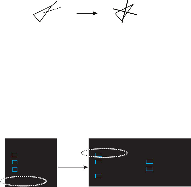
3.7 Lost Target
When AIS data is not received from a target within 3-5 report intervals (see Note 2),
the target symbol changes to the lost target symbol (flashing). No audio or visual alarm
is given for a lost target.
Note: The AIS data transmission interval depends on target’s speed. For example, the
data is transmitted every 10 seconds on ship speed of 0 to 14 knots and every two
seconds on the ship speed of more than 23 knots. For details see the operator’s
manual of the AIS transponder.
3.7.1 Lost target filter
If there are a lot of AIS targets in your area, the lost target alarm may sound frequently.
In this case you may wish to have the alarm ignore lost targets whose range, speed,
class or length are below the threshold value you specify.
1. Right-click the [AIS] icon to show [AIS TARGET MENU].
2. Click [AIS LOST FILTER].
3. Click [AIS LOST FILTER] in the [AIS LOST FILTER] menu.
4. Click the target alarm to enable.
[OFF]: Disable the alarm.
[FILT]: Get the alarm against the targets whose criteria meet the settings on the
[AIS LOST FILTER] menu.
[ALL]: Get the alarm against all lost targets.
5. Click [MAX RANGE VALUE] and [MIN SHIP SPEED VALUE] as appropriate,
referring to the description below.
[MAX RANGE], [MAX RANGE VALUE]: Any AIS lost target beyond the range set
here is not shown.
[MIN SHIP SPEED], [MIN SHIP SPEED VALUE]: Any AIS lost target slower than
this setting is not shown.
[EXCEPT CLASS B]: Select [ON] to prevent trigger lost Class B AIS lost target.
[MIN SHIP LENGTH], [MIN SHIP LENGTH VALUE]: Any AIS lost target whose
length is shorter than this setting is not shown.
3.7.2 How to acknowledge a lost target
1. Click the [AIS] icon to show [AIS TARGET MENU].
2. Right-click [ACK LOST TARGETS].
3. Click [YES]. The lost target disappears from the screen.
Activated target Lost target
[AIS TARGET MENU]
1 BACK
2 SLEEP ALL TARGETS
NO/YES
3 ACTIVATE ALL TARGETS
NO/YES
4 ACK LOST TARGETS
NO/YES
5 [AIS DISP FILTER]
6 [CPA AUTO ACTIVATE]
7 [AIS LOST FILTER]
[AIS LOST FILTER]
1 BACK
2 AIS LOST FILTER
OFF/FILT/ALL
3 MAX RANGE
OFF/ON
4 MAX RANGE VALUE
03.0km
5 MIN SHIP SPEED
OFF/ON
6 MIN SHIP SPEED VALUE
00.0km/h
7 EXCEPT CLASS B
OFF/ON
8 MIN SHIP LENGTH
OFF/ON
9 MIN SHIP LENGTH VALUE
000m
Click
3. AIS OPERATION
3-8
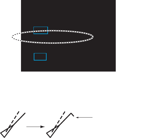
3.8 ROT Setting
You may set the lower limit of the ROT (Rate Of Turn) at which the heading line on
target symbols points the ship’s turning direction.
1. Open [MAIN MENU], click [TT.AIS].
2. Click [SYMBOL].
3. Click [AIS].
4. Click [ROT TAG LIMIT].
5. Click the setting value then enter ROT with the setting knob (setting range: 0.1 to
720.0 (deg/min)).
6. Click outside the menu window to close the menu.
3.9 CPA/TCPA Alarm
The AIS continuously monitors the predicted range at the Closest Point of Approach
(CPA) and predicted time to CPA (TCPA) of each AIS target. When the predicted CPA
of an AIS target becomes smaller than a preset CPA range and its predicted TCPA
less than a preset TCPA limit, the audio alarm sounds. In addition, the symbol of the
offending AIS target is red and flashes together with its vector.
CPA/TCPA alarm ranges must be set up properly taking into consideration the size,
tonnage, speed, turning performance and other characteristics of own ship.
The reference point for CPA, TCPA calculation may be selected from antenna position
or conning position.
To set this alarm, see section 2.12 "CPA/TCPA Alarm".
[AIS]
1 BACK
2 SYMBOL COLOR
GRN/BLU/CYA/MAG/WHT
3 ROT TAG LIMIT
000.0deg/min
4 SCALED SYMBOL
OFF/ON
Ship turning to
starboard
3. AIS OPERATION
3-9
3.10 Automatic Target Activation
You can get automatic activation of a sleeping AIS target when its CPA is within the
CPA/TCPA alarm setting. Further, you can select which AIS targets to automatically
activate.
1. Right-click the [AIS] icon to show the [AIS TARGET MENU] window.
2. Click [CPA AUTO ACTIVATE].
3. Click [CPA AUTO ACTIVATE].
4. Click the activating mode for AIS target.
[OFF]: Disable automatic activation of AIS target by CPA.
[FILT]: Activate only the targets that fulfill the requirements set on the [CPA AUTO
ACTIVATE] menu.
[ALL]: For all targets.
5. Set items 3 to 9 referring to the description below.
[MAX RANGE], [MAX RANGE VALUE]: Any AIS target beyond the range set here
will not be activated.
[MIN SHIP SPEED], [MIN SHIP SPEED VALUE]: Any AIS target slower than this
setting will not be activated.
[EXCEPT CLASS B]: Select [ON] to prevent automatic activation of class B AIS
targets.
[MIN SHIP LENGTH], [MIN SHIP LENGTH VALUE]: Any AIS target whose length
is shorter than this setting will not be activated.
6. Click outside the menu window to close the menu.
[AIS TARGET MENU]
1 BACK
2 SLEEP ALL TARGETS
NO/YES
3 ACTIVATE ALL TARGETS
NO/YES
4 ACTIVATE ALL TARGETS
NO/YES
5 [AIS DISP FILTER]
6 [CPA AUTO ACTIVATE]
7 [AIS LOST FILTER]
[CPA AUTO ACTIVATE]
1 BACK
2 CPA AUTO ACTIVATE
OFF/FILT/ALL
3 MAX RANGE
OFF/ON
4 MAX RANGE VALUE
03.0km
5 MIN SHIP SPEED
OFF/ON
6 MIN SHIP SPEED VALUE
00.0km/h
7 EXCEPT CLASS B
OFF/ON
8 MIN SHIP LENGTH
OFF/ON
9 MIN SHIP LENGTH VALUE
000m

3. AIS OPERATION
3-10
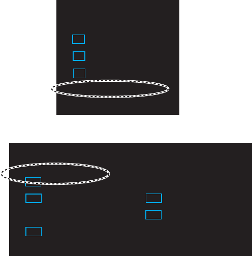
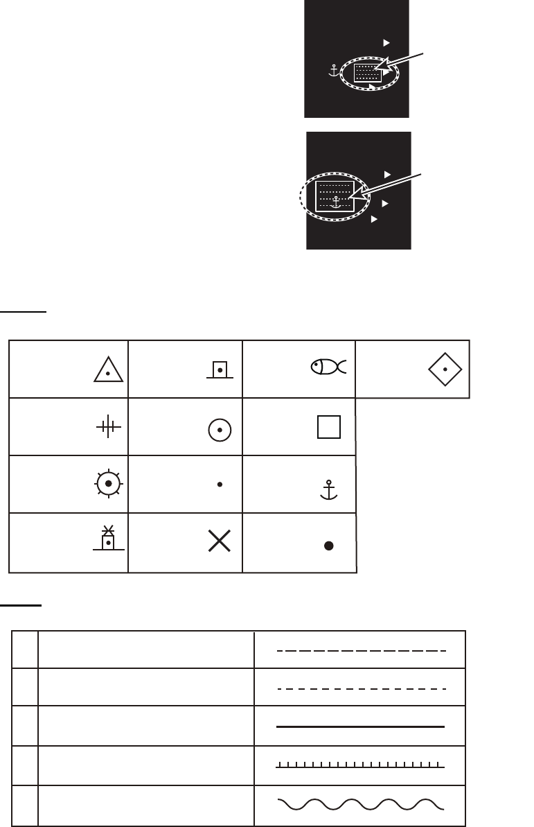
3.11 AIS Target Data
You may display an AIS target’s data by selecting it on the display. This data is shown
for the activated AIS target only. The selected AIS target is enclosed in a broken
square. The target data is shown on the [AIS INFO] window.
[AIS INFO] window
Symbol operation
Left-click the AIS target to show the selected target's information window.
Menu operation
1. Right-click the AIS target to show the [AIS] window.
2. Click [TARGET DATA] to show the [AIS INFO] window.
3. Click the close button or outside the information window to close the menu.
[NAME]: Name of ship [RNG/BRG]: Range/Bearing to target
[FLAG]: Flag state [SOG/COG] (or [STW/CTW]): Target’s
speed and course
[CALL SIGN]: Call sign
[MMSI]: MMSI No. [CPA/TCPA]: Target’s CPA/TCPA
[IMO NO.]: IMO No. [HDG]: Heading
[LAT]: Latitude [ROT]: Rate of turn
[LON]: Longitude [LEN/BEAM]: Ship’s length/Beam
[BLUE SIGN]: Blue sign status
AIS Selected AIS to
display the information
[AIS INFO]
NAME :XXXX
FLAG :NETHERLANDS
CALL SIGN :PFXXXX
MMSI :123456789
IMO NO. :missing
LAT :51°53.661’ N
LON :004°18.376’ E
RNG/BRG :0.77km/324.4°R
SOG/COG :11.1km/h/100.0°T
CPA/TCPA :0.49km/03m10s
HDG :missing
ROT :missing
LEN/BEAM :135m/14.0m
BLUE SIGN :NO
[AIS]
1 BACK
2 TARGET DATA
3 ACTIVE/SLEEP
3. AIS OPERATION
3-11
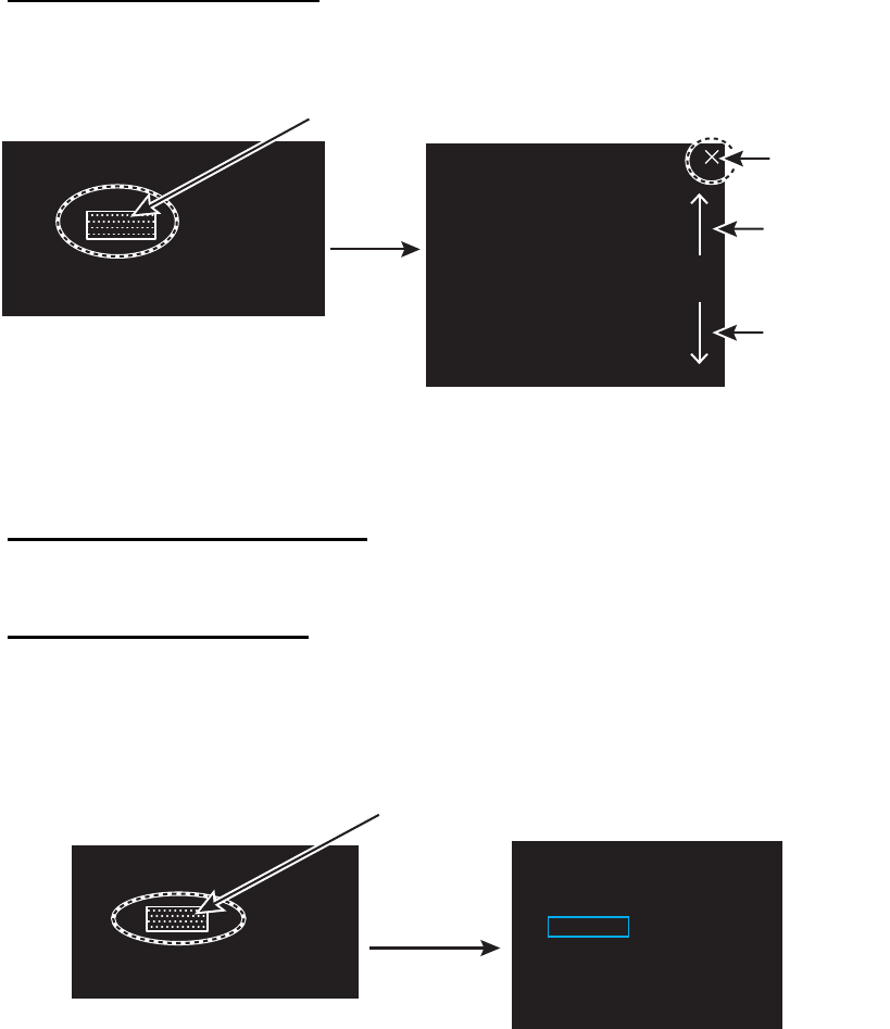
3.12 AIS List
The AIS list provides a comprehensive information about all AIS targets being tracked.
How to display the AIS list
Click the [LIST] icon for AIS at the bottom right corner on the screen.
You can see [MMSI] and [NAME] for AIS targets. To close the [AIS LIST] window, click
the close button on the list.
How to display AIS target data
Click the target on [AIS LIST] to show the [AIS INFO] window. See section 3.11.
How to sort the target list
You may sort the target list by RANGE, CPA, TCPA. Also, you can sort in ascending
or descending order.
1. Right-click the [LIST] icon for AIS to show the [AIS-LIST] window.
2. Click [SORT BY].
3. Click the sorting method desired.
[NAME-UP], [NAME-DOWN]: Sort by name
[RANEG-UP], [RANGE-DOWN]: Sort by range
[CPA-UP], [CPA-DOWN]: Sort by CPA
[TCPA-UP], [TCPA-DOWN]: Sort by TCPA
4. Click outside the menu window to close the menu.
Close
button
[AIS LIST] <SORT>NAME-UP 1/1
MMSI NAME
12XXXXXXXXX ABCXX
2345XXXXXXX AXX
[LIST] icon for AIS
[LIST] icon for AIS
AIS list
AIS
FLT►
VRM1 1.567
VRM2 0.160
NAV 0 160
NM
LIST►
NM
NM
MA
N
MA
N
MAN
AUTO
01m0
13m
REL
ON
TUN
E
Page up
button
Page down
button
Click
[AIS-LIST]
1 BACK
2 SORT BY
NAME-UP /NAME-DOWN/
RANGE-UP/RANGE-DOWN/
CPA-UP/CPA-DOWN/
TCPA-UP/TCPA-DOWN
[LIST] icon for AIS
[LIST] icon for AIS
AIS
FLT
►
VRM1
1.567
VRM2
0.160
NAV
0 160
NM
LIST►
NM
NM
MA
N
MA
N
MAN
AUTO
01m0
13m
REL
ON
TUN
E
Right-click
3. AIS OPERATION
3-12
This page is intentionally left blank.
4-1
4. RADAR MAP
4.1 What is a Radar Map?
The radar map feature, available in the [RIVER] mode, is a combination of map lines
and symbols whereby the user can define and input the navigation, route planning and
monitoring data on the screen. Map lines are a navigational facility whereby the
observer can define lines to indicate channels or traffic separation schemes.
The user can create a radar map on real-time base while using the radar for navigation
or at leisure time at anchor. The map data is stored on the Flash ROM memory which
is mounted on the main processor board.
Note: Radar map function requires heading and positioning data.
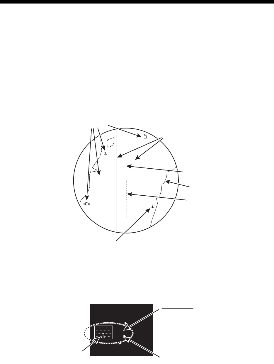
4.2 [MARK] icon
The [MARK] icon, located at the bottom left corner on the screen, is used to create
marks and lines, line operations. This radar can save a total of 5,000 marks and lines.
Navlines
(by NAV LINE icon)
Heading line
Stern mark
Approximate
coast line
X
Mark symbols
Mark symbols
MENU
BARGE ON
2WHT
ON
CYA DOCK OF
F
BRL2-3
ECHO
BIN
GRN
BLK
MARK
MARK
Mark shape Color of the mark
Display icon
[ON]: Shows all the marks
currently selected at the
[MARK] icon.
[OFF]: Hides all marks currently
selected at the [MARK]
icon.
[MARK] icon
4. RADAR MAP
4-2
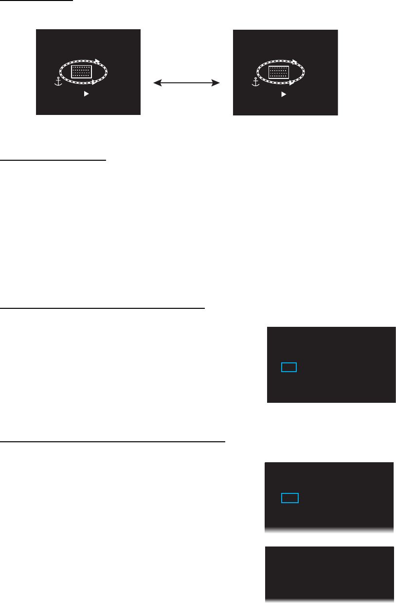
4.3 How to Enter Marks, Lines
4.3.1 How to enter a mark, line with at the cursor position
1. Click the mark color icon to select the re-
quired color for the mark.
2. Highlighting the [MARK] icon then rotate
the setting knob to select a mark.
3. Press the left button on the appropriate mark to decide the mark (or line) shape.
Marks
Lines
4. Press the left button. For lines, press the left button on the next point of the line
then repeat this operation to complete the line.
5. Press the right button to quit.
MENU
BARGE ON
2WHT
ON
CYA D
O
BRL2-3
ECHO
B-IN
GRN
BLK
MARK
MARK
Mark color icon
MENU
BARGE ON
2WHT
OFF
CYA D
O
BRL2-3
ECHO
B-IN
GRN
BLK
MARK
MARK
[MARK] icon
Triangle
Lighthouse 1
Lighthouse 2
Lighthouse 3
Circle
Small dot
Cross
Fish
Square
Anchor
Dot
Dash with
3 bar-line
Diamond
Dashed line
Coast line
Contour line / Prohibited areas
Cable
Long dashed line
1
2
3
4
5

4. RADAR MAP
4-3
4.3.2 How to enter a mark by latitude and longitude position input
This function is not available for entering lines.
1. Right-click the [MARK] icon to show the [MARK
ICON] window.
2. Click [CREATE] to show the [CREATE] window.
3. Click [ENTER BY LL].
4. The cursor is on the far left-hand digit on the latitude line. Rotate the setting knob
to click a numeral. The cursor moves to the next digit. Enter other numbers
similarly.
5. Right-click the last digit to finish.
4.3.3 How to enter a mark at current position
This function is not available for entering lines.
1. Right-click the [MARK] icon to show the [MARK ICON] window.
2. Click [OWN SHIP].
4.4 Mark/Line information
You can confirm the number of marks and lines which you have entered.
1. Open [MAIN MENU], click [RADAR MAP].
2. Click [MARK/LINE INFO] to open the information window.
[MARK ICON]
1 BACK
2 [CREATE]
3 OWN SHIP
[CREATE]
1 BACK
2 ENTER BY LL
00°00. 000 N
000°00. 000 E
3 CREATE
[MARK/LINE INFO]
1 BACK
2 MARK/LINE INFO
CURRENT NUMBER
:100
TOTAL CAPACITY:5000
4. RADAR MAP
4-4
4.5 How to Show, Hide Marks on the Screen
By menu icon
Click the mark display icon to show or hide the marks.
By [DISPLAY] menu
This menu is available in the [RIVER] mode only.
1. Open [MAIN MENU], click the [DISPLAY] menu.
2. Click [MARK/LINE].
3. Click [ON] or [OFF].
4.6 How to Delete Marks, Lines
How to delete marks, lines individually
1. Right-click the mark to delete.
2. Click [DELETE].
3. Click [YES].
How to delete marks, lines by color, shape
1. Open [MAIN MENU], click [RADAR MAP] to show
the [RADAR MAP] menu.
2. Click [DATA DELETE].
Display icon: [ON] Display icon: [OFF]
MENU
BARGE ON
2WHT
ON
CYA DOCK OF
F
BRL2-3
ECHO
BIN
GRN
BLK
MARK
MARK
MENU
BARGE ON
2WHT
OFF
CYA DOCK OF
F
BRL2-3
ECHO
BIN
GRN
BLK
MARK
MARK
Click
[MARK]
1 BACK
2 DELETE
NO/YES
1 BACK
2 MAP ALIGN
OFF/ON
3 [MARK/LINE INFO]
4 [DATA DELETE]
[RADAR MAP]
1 BACK
2 [MARK/LINE DELETE]
3 [BARGE DELETE]
[DATA DELETE]

4. RADAR MAP
4-5
3. Click [MARK/LINE DELETE].
4. Click the sort to delete.
[SHAPE DELETE]: Select the shape to delete then
select [YES] in [DELETE].
[COLOR DELETE]: Select the color to delete then select [YES] in [DELETE].
5. Click [DELETE].
6. Click [YES].
7. Click outside the menu window to close the menu.
How to delete all marks, lines
1. Open [MAIN MENU], click [RADAR MAP] to show the [RADAR MAP] menu.
2. Click [DATA DELETE].
3. Click [MARK/LINE DELETE].
4. Click [MARK/LINE ALL DELETE].
5. Click [YES].
6. Click outside the menu window to close the menu.
4.7 How to Align the Radar Map
When the map is not overlaid on the radar picture correctly, you can align the map with
the [MAP ALIGN] menu.
1. Open [MAIN MENU], click [RADAR MAP].
2. Click [MAP ALIGN].
3. Click [ON] to align the radar echo to the radar map. The cursor moves the center
of the radar display. The mark symbols are moved in conjunction with the cursor
movement.
4. Click anywhere in the radar display to complete the alignment.
[MARK/LINE DELETE]
1 BACK
2 [SHAPE DELETE]
3 [COLOR DELETE]
4 MARK/LINE ALL DELETE
NO/YES
1 BACK
2 MAP ALIGN
OFF/ON
3 [MARK/LINE INFO]
4 [DATA DELETE]
[RADAR MAP]
4. RADAR MAP
4-6
This page is intentionally left blank.
5-1
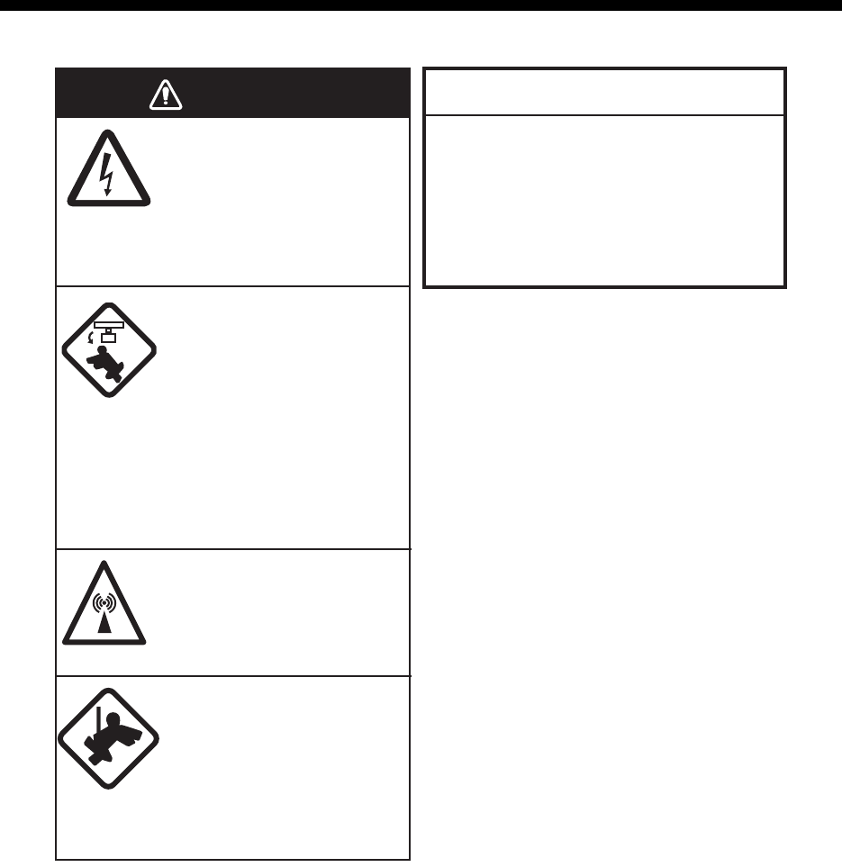
5. MAINTENANCE, TROUBLE-
SHOOTING
Do not open the equipment.
Hazardous voltage which can
cause electrical shock exists
inside the equipment. Only
qualified personnel should
work inside the equipment.
Turn off the radar power
switch before servicing the
antenna unit. Post a warn-
ing sign near the switch
indicating it should not be
turned on while the antenna
unit is being serviced.
Prevent the potential risk of
being struck by the rotating
antenna.
A transmitting radar
antenna emits electromag-
netic waves, which can be
harmful, particularly the
eyes.
Wear a safety belt and hard
hat when working on the
antenna unit.
Serious injury or death can
result if someone falls from
the radar antenna mast.
Do not apply paint, anti-corrosive sealant
or contact spray to coating or plastic
parts of the equipment.
Those items contain organic solvents that
can damage coating and plastic parts,
especially plastic connectors.
WARNING
NOTICE
5. MAINTENANCE, TROUBLESHOOTING
5-2
5.1 Preventive Maintenance
Regular maintenance helps keep your equipment in good condition and prevents
future problems. Check the items shown on next page to help keep your equipment in
good condition for years to come.
Ground terminal on processor units
Tighten or replace as necessary.
Connectors on monitor and processor units
Tighten if the connectors are loosened.
Exposed nuts and bolts on the antenna unit
Exposed bolts and nuts are subject to corrosion. Further, they may loosen by
vibration. Check that bolts and nuts are securely fastened. Refasten if necessary.
If corroded, and coat with anti-corrosive sealant.
Antenna radiator
Dust, dirt and salt deposits on the radiator cause signal attenuation, resulting in loss
of sensitivity. Wipe radiator with a freshwater-moistened cloth. The radiator is made of
fiber-glass reinforced plastic. Therefore, do not used gasoline, benzene and the like
to clean the radiator. If the radiator is iced, use a wooden or plastic headed hammer
to remove the ice.
5.2 Parts Replacement
Fuse
The fuse in the processor unit protects the equipment from overcurrent and equipment
fault. If the fuse blows, find the cause before you replace the fuse. Use the correct
fuse. A wrong fuse can damage the equipment.
Magnetron
The magnetron gradually deteriorates over time. When long distance sensitivity
decreases greatly, request replacement of the magnetron.
Other consumable parts
Unit Type Code No. Remarks
Processor Unit FGBO-A 125V 10A PBF 000-155-826-10 24 VDC
Model Magnetron Type Code No. Estimated life
FR-1908V-BB MAF1611B, X-band, 4 kW — Approx. 3,000 hours
Parts Type Estimated life
Motor D8G-516 (26 rpm) Approx. 10,000 hours
Carbon Brush S755123-1A-02 Approx. 2,000 hours
Use the correct fuse.
A wrong fuse can damage the equipment
and cause fire.
WARNING

5. MAINTENANCE, TROUBLESHOOTING
5-3
5.3 Diagnostic Test
5.3.1 Self Test
The diagnostic test checks the system for correct operation. This test is for use by
ser-vice technicians, but the user can do this test to provide the service technician with
information.
1. Open [MAIN MENU], click [CONFIGURATION].
2. Click [TEST].
3. Click [SELF TEST]. Test results of mother board, control unit and processor unit
are displayed. Items 5 to 10 are displayed [OK] if normal and [NG] if abnormal.
When [NG] is displayed, request a service.
4. To close the window, click the close button (×).
5. Click outside the menu window to close the menu.
5.3.2 NMEA sentences checks
You can check the sentences read into the equipment.
1. Open [MAIN MENU], click [CONFIGURATION].
2. Click [TEST].
3. Click [SENTENCE MONITOR].
4. Click the item to display. Each item refers to the external equipment connection
port in the processor unit.
5. To close the window, click the close button (×).
6. Click outside the menu window to close the menu.
*: [RIVER] mode only
**: [SEA] mode only
[MAIN MENU]
1 BACK
2 [ECHO]
3 [DISPLAY]
4 [MARK]
6 [RADAR MAP]*
7 [NAV DATA]
8 [FILES]
9 [CAPTURE]
10 [CONFIGURATION]
11 [ALARM]
12 [TT•AIS]**
[CONFIGURATION]
1 BACK
2 [OPERATION]
3 [FUNCTION KEY]
4 [TEST]
[TEST]
1 BACK
2 SELF TEST
3 [SENTENCE MONITOR]
[SENTENCE MONITOR]
1 BACK
2 NMEA1
3 NMEA2
4 NMEA3
5 NMEA4
6 NMEA5
7 NMEA6

5. MAINTENANCE, TROUBLESHOOTING
5-4
5.4 Easy Troubleshooting
This section provides troubleshooting procedures that the user may follow to restore
normal operation. If you cannot restore normal operation, do not attempt to check
inside any unit. Leave any repair work to a qualified technician.
Easy troubleshooting
Problem Remedy
You can not turn on the power. • Check for blown fuse.
• Check that the power connector is fastened.
• Check for corrosion on the power cable connector.
• Check for damaged power cable.
• Check the input source for monitor.
There is no response when a key
is pressed.
Long press the POWER key for approx. seven seconds to turn
off the power. Then, turn on the power again.
Key beep inaudible Adjust key beep level on the [OPERATION] menu, referring to
paragraph 1.37.4.
Picture not updated or picture
freeze.
Long press the POWER key for approx. seven seconds to turn
off the power. Then, turn on the power again.
The power is on and you operated
the STBY/TX key to transmit. The
marks and characters appear, but
no echo appears.
• Check that the antenna cable is fastened.
• Adjust the GAIN and STC levels.
• Adjust the echo brilliance.
Tuning is correctly adjusted, but
sensitivity is poor.
• Clean the radiator face.
• Replace the magnetron. Contact your dealer.
There are unwanted echo around
own ship.
Adjust the STC level.
• The icons are automatically
hidden.
• You can not find the icon.
Turn [HIDDEN ICON] to [OFF]. See paragraph 1.36.2.
You can not adjust the brilliance of
the screen.
Turn [EXT BRILL CTRL] to [ON] on the monitor MU-190RH.
You can not set the orientation
mode.
• Check the connected equipment.
• Check the heading input (Sentence monitor, Input port,
Baud rate).
• The AIS symbols are not
shown.
• The true trails are not shown.
• The radar map is not shown.
Check the connected equipment.
Range rings are not shown. Adjust their brilliance with [FIXED RING]. See
paragraph 1.6.3.

5. MAINTENANCE, TROUBLESHOOTING
5-5
5.5 Advanced Troubleshooting
This section describes how to cure hardware and software troubles that should be
carried out by qualified service personnel.
Advanced troubleshooting
Problem Probable causes or
check points Remedy
You cannot turn on the
power.
• Blown fuse.
• Mains voltage/polarity
• Power supply board
• Replace blown fuse.
• Correct wiring and input voltage.
• Replace power supply board.
Power turned on but radar
does not operate at all.
Panel board Replace panel board.
Antenna not rotating • Antenna switch setting (See
the Installation manual.)
• Check for the voltage for
motor.
• Antenna switch of antenna
unit
• Gear mechanism
• RF_TB board
• Check the setting of antenna
switch.
• Replace PSU board.
• Check if antenna switch is ON.
• Replace the motor.
• Replace RF_TB board.
Set [GAIN] to maximum
with [STC] and [RAIN]
settings at minimum. Marks
and indications appear but
no noise or echo.
• IF amplifier
• Signal cable between
antenna and processor unit
• VIDEO_AMP board
• SPU cable connection on the
VIDEO_AMP board
• Replace IF amplifier.
• Check continuity and isolation of
coaxial cable.
• Replace video amplifier.
Marks, indications and
noise appear but no echo in
short range.
• Magnetron
• Modulator board
• SPU board
• Check magnetron current.
• Replace modulator board.
• Replace SPU board.
Picture not updated or
picture freeze-up.
• Bearing signal generator
• SPU board
• Check that signal cables are
fastened.
• Replace SPU board.
• Turn off and on the radar.
GAIN is poor. Tuning Do the [TUNE INITIALIZE] setting.
See paragraph 1.8.4.
Radar is correctly tuned but
sensitivity is poor.
• Deteriorated magnetron
• Dirt on radiator face
• Check the magnetron current
with the radar transmitting
on 48 nm range.
• Clean radiator.
5. MAINTENANCE, TROUBLESHOOTING
5-6
This page is intentionally left blank.

AP-1
APPENDIX 1 RADIO REGULATORY
INFORMATION
USA-Federal Communications Commission (FCC)
This device complies with part 15 of the FCC Rules. Operation is subject to the following two conditions:
(1) This device may not cause harmful interference, and
(2) This device must accept any interference received, including interference that may cause undesired
operation. Any changes or modifications not expressly approved by the party responsible for
compliance could void the user's authority to operate the equipment.
Caution: Exposure to Radio Frequency Radiation
• This equipment complies with FCC radiation exposure limits set forth for an uncontrolled environment
and meets the FCC radio frequency (RF) Exposure Guidelines in Supplement C to OET65.
• This equipment should be installed and operated keeping the radiator at least 50 cm or more away
from person's body.
• This device must not be co-located or operating in conjunction with any other antenna or transmitter.
AP-2
APPENDIX 2 MENU TREE
MAIN MENU
6 RADAR MAP***
4 MARK
3 DISPLAY
2 ECHO
1 BACK*
1 BACK
2 TUNE INITIALIZE
3 STC PRESET (OFF, ON)
4 FTC PRESET (OFF, ON)
1 BACK
2 OWN SHIP MARK (MIN, RECTANGLE, PENTAGON)
3 STERN MARK (OFF, ON)
4 EBL OFFSET BASE* (STAB GND, STAB HDG, STAB NORTH)
5 VRM SYNC OFFSET EBL* (OFF, ON)
1 BACK
2 TRANSPARENCY (OFF, ON)
3 DOCKING MODE (OFF, ON)
4 OWN SHIP MARK (OFF, ON)
5 MENU
6 HIDDEN ICON
7 MARK/LINE*** (OFF, ON)
8 BARGE*** (OFF, ON)
9 ECHO AREA* (CIRCLE, WIDE)
1 BACK
2 AUTO-CLOSING* (OFF, ON)
3 AUTO-CLOSING TIME* (5sec, 10sec, 20sec)
1 BACK
2 AUTO-HIDDEN (OFF, ON)
3 AUTO-HIDEN TIME
(5sec, 10sec, 20sec)
4 RANGE (OFF, ON)
5 MODE (OFF, ON)
6 NAV DATA (OFF, ON)
7 MARK (OFF, ON)
8 BRILL/COLOR (OFF, ON)
9 TT/AIS (OFF, ON)
10 ECHO (OFF, ON)
11 GAIN/STC/RAIN (OFF, ON)
12 EBL/VRM (OFF, ON)
13 DOCKING (OFF, ON)
MAIN MENU
(TO NEXT PAGE)
*: [SEA] mode only
***: [RIVER] mode only
1 BACK
2 MAP ALIGN (OFF, ON)
3 MARK/LINE INFO
4 DATA DELETE
1 BACK
2 MARK/LINE INFO
(CURRENT NUMBER,
TOTAL CAPACITY: 5000)
1 BACK
2 MARK/LINE DELETE
3 BARGE DELETE
1 BACK
2 SHAPE DELETE
3 COLOR DELETE
4 MARK/LINE ALL DELETE (NO, YES)
1 BACK
2 SHAPE (Select one)
3 DELETE (NO, YES)
1 BACK
2 COLOR
(GRN, BLU, YEL, CYA,
MAG, WHT)
3 DELETE (NO, YES)
1 BACK
2 COLOR (GRN, BLU, YEL, CYA,
MAG, WHT)
3 BARGE ALL DELETE (NO, YES)
APPENDIX 2 MENU TREE
AP-3
7 NAV DATA
8 FILES
9 CAPTURE
(FROM PREVIOUS PAGE)
1 BACK
2 PREDICTION
3 DEPTH
4 WIND
5 ROT SCALE (30deg, 90deg, 300deg)
6 RUDDER SCALE (30deg, 90deg, 120deg, 180deg)
1 BACK
2 OWN SHIP POSITION (DUAL-GPS, SC)
1 BACK
2 GRAPH TYPE
(NUMERICAL, GRAPHICAL)
3 DUAL SENSOR (BOTH, FRONT, AFT)
4 DEPTH SCALE
5 TIME SCALE (15sec, 30sec, 1min, 3min)
6 DEPTH ALARM VALUE (0.00 - 9.99 m, 5.00)
1 BACK
2 SCALE TYPE
(RIVER, SEA)
3 RIVER (4, 10, 40)
4 SEA
(10, 20, 50, 100, 200, 500)
1 BACK
2 WIND DIRECTION (OFF, COME FROM, GO TO)
(TO NEXT PAGE)
1 BACK
2 DRIVE SELECT (SD-1, SD-2)
3 DRIVE INFO
4 SAVE DATA
5 REPLAY (READ) DATA
6 DELETE DATA
7 REMOVE EXTERNAL MEDIA (SD-1, SD-2)
1 BACK
2 DRIVE INFO (USED, AVAILABLE)
1 BACK
2 MARK/LINE*** (1 BACK, 2 NAME)
3 SETTING DATA (1 BACK, 2 NAME)
4 INSTALL DATA**
5 ALARM HISTORY (1 BACK, 2 NAME)
6 LOG FILE (1 BACK, 2 NAME)
1 BACK
2 MARK/LINE*** (1 BACK, 2 NAME)
3 SETTING DATA (1 BACK, 2 NAME)
4 INSTALL DATA**
1 BACK
2 MARK/LINE*** (1 BACK, 2 NAME)
3 SETTING DATA (1 BACK, 2 NAME)
4 INSTALL DATA**
5 ALARM HISTORY (1 BACK, 2 NAME)
6 LOG FILE (1 BACK, 2 NAME)
**: For service menu
1 BACK
2 DRIVE SELECT (SD-1, SD-2)
3 DRIVE INFO
4 AUTO CAPTURE
5 DELETE CAPTURE DATA
6 REMOVE EXTERNAL MEDIA (SD-1, SD-2)
1 BACK
2 DRIVE INFO (
THE NUMBER OF FILES, USED, AVAILABLE
)
1 BACK
2 AUTO CAPTURE (OFF, ON)
3 INTERVAL (1 to 999 min, 1)
1 BACK
2 MANUAL DATA (1 BACK(LONG=TOP), 2 DELETE)
3 AUTO(FAST) DATA (1 BACK(LONG=TOP), 2 DELETE)
4 AUTO(NORMAL) DATA (1 BACK(LONG=TOP), 2 DELETE)
*: [SEA] mode only
***: [RIVER] mode only
(available in
stand-by mode
only)
(available in
stand-by mode
only)

APPENDIX 2 MENU TREE
AP-4
10
CONFIGURATION
(FROM PREVIOUS PAGE)
1 BACK
2 OPERATION
3 FUNCTION KEY
1 BACK
2 REF POINT (ANT, CCRP)
3 KEY BEEP (OFF, LOW, MID, HIGH)
4 OWN SHIP VECTOR (OFF, COURSE, HDG)
5 CURSOR SIZE (SMALL, LARGE)
6 GUIDANCE (OFF, ON)
7 TOUCH PAD
8 POINTING-DEVICE
1 BACK
2 TOUCH-PAD (OFF, ON)
3 SENSITIVITY (1, 2, 3, 4, 5)
1 BACK
2 POINTING-DEVICE
(OFF, ON)
3 SENSITIVITY (1, 2, 3, 4, 5)
1 BACK
2 F1
3 F2 (Same as [F1], Default: [DOCKING])
1 BACK
2 ECHO
3 STD KEY
4 TT•AIS
5 OPERATION
6 BRILL
7 CUSTOM
1 BACK
2 CUSTOM-MENU, FTC, IR, ES, EAV,
AUTO-GAIN, AUTO-STC, AUTO-RAIN, TUNE SELECT,
TRAIL DISPLAY, TRAIL TIME, TRAIL T/R, WIPER
1 BACK
2 ALARM ACK, EBL OFFSET, OPERATION MODE,
ORIENTATION-MODE, CU-TM RESET*, VECTOR TIME,
VECTOR MODE, TT-LIST
*
, AIS-LIST, BRILL-MENU, MARK
***
,
CAPTURE
1 BACK
2 TT-DISP
*
, AIS-DISP, PAST POSN INTERVAL, REF MARK
*
,
CPA LIMIT, CPA, TCPA, AZ1
*
, AZ2
*
, AIS SCALED SYMBOL
1 BACK
2 ECHO COLOR, MONITOR BRILL, PANEL DIMMER,
TRANSPARENCY, ALARM1
*
, ALARM2
*
, ECHO AREA
*
,
DOCKING, MARK/LINE-ON
***
, BARGE-ON
***
, MAP ALIGN
***
,
MARK/LINE ALL DELETE
***
, BARGE ALL DELETE
***
1 BACK
2 USER NAME 1 (BRL1-1 - BRL1-4)
3 USER NAME 2 (BRL2-1 - BRL2-4)
4 USER NAME 3 (BRL3-1 - BRL3-4)
5 USER NAME 4 (BRL4-1 - BRL4-4)
1 BACK
2 USER NAME 1 (CUSTOM1-1 - CUSTOM1-4)
3 USER NAME 2 (CUSTOM2-1 - CUSTOM2-4)
4 USER NAME 3 (CUSTOM3-1 - CUSTOM3-4)
5 USER NAME 4 (CUSTOM4-1 - CUSTOM4-4)
(TO NEXT PAGE)
*: [SEA] mode only
***: [RIVER] mode only

APPENDIX 2 MENU TREE
AP-5
11 ALARM
12 TT•AIS
(FROM PREVIOUS PAGE)
1 BACK
2 TT•AIS
3 TARGET
ALARM*
1 BACK
2 ALR1 MODE (IN, OUT)
3 ALR2 MODE (IN, OUT)
4 LEVEL (1, 2, 3, 4)
1 BACK
2 CPA LIMIT (OFF, ON)
3 RANGE (0.1 - 24 NM, 1 NM)
4 TIME (30sec, 1-15min, 1min)
1 BACK
2 CPA LIMIT
1 BACK
2 NMEA1
3 NMEA2
4 NMEA3
5 NMEA4
6 NMEA5
7 NMEA6
1 BACK
2 SELF TEST
3 SENTENCE MONITOR
1 BACK
2 VECTOR
3 PAST POSN
4 SYMBOL
5 ACUQIRE ZONE*
1 BACK
2 VECTOR MODE
(Ground-Stab: VECTOR REL, VECTOR T-G
Sea-Stab: VECTOR REL, VECTOR T-S
3 VECTOR TIME (30sec, 1 - 6min, 1min)
1 BACK
2 AZ STAB (STAB NORTH, STAB HEADING)
3 POLYGON STAB (OFF, STAB GND, STAB NORTH,
STAB HEADING)
1 BACK
2 AIS
3 TT* 1 BACK
2 SYMBOL COLOR (GRN, BLU, CYA, MAG, WHT)
1 BACK
2 SYMBOL COLOR (GRN, BLU, CYA, MAG, WHT)
3 ROT TAG LIMIT
(000.1 - 720.0 deg/min, 000.1 deg/min)
4 SCALED SYMBOL (OFF, ON)
1 BACK
2 INTERVAL (OFF, 0.5 min, 1 min, 2 min, 3 min, 6 min)
3 POINTS (5, 10)
*: [SEA] mode only
4 TEST
(Protected as
[SERVICE
MENU] in
[RIVER] mode)
(Protected as
[SERVICE
MENU] in
[RIVER] mode)

AP-6
APPENDIX 3 DIGITAL INTERFACE
(IEC61162-1)
Input sentences
ALR : Set alarm state
DBS : Depth Below Surface
DBT : Depth Below Transducer
DPT : Depth
DTM : Datum Reference
$**ALR,Hhmmss.ss,xxx,A,A,c—c,*hh<CR><LF>
1 2 3 4 5
1. Time of alarm condition change, UTC (000000.00 - 240001.00)
2. Unique alarm number (identifier) at alarm source (000 - 999)
3. Alarm condition (A=threshold exceeded, V=not exceeded)
4. Alarm acknowledge state (A=acknowledged, V=not acknowledged)
5. Alarm description text (alphanumeric)
$**DBS,x.x,f,x.x,M,x.x,F,*hh<CR><LF>
1 2 3 4 5 6
1. Water depth (0.00-99999.99)
2. feet
3. Water depth (0.00-99999.99)
4. Meters
5. Water depth (0.00-99999.99)
6. Fathom
$**DBT,xxxx.x,f,xxxx.x,M,xxxx.x,F,*hh<CR><LF>
1 2 3 4 5 6
1. Water depth (0.00-99999.99)
2. feet
3. Water depth (0.00-99999.99)
4. Meters
5. Water depth (0.00-99999.99)
6. Fathoms
$**DPT,x.x,x.x,x.x,*hh<CR><LF>
1 2 3
1. Water depth relative to the transducer, meters (0.00-99999.99)
2. Offset from transducer, meters (-99.99 - 99.99)
3. Minimum range scale in use (no use)
$**DTM,ccc,a,x.x,a,x.x,a,x.x,ccc,*hh<CR><LF>
1 2 3 4 5 6 7 8
1. Local datum (W84=WGS84 W72=WGS72 S85=SGS85, P90=PE90
User defined=999, IHO datum code
2. Local datum subdivision code (NULL or one character)
3. Lat offset, min (-59.99999 - 59.59999)
4. N/S
5. Lon offset, min (no use)
6. E/W
7. Altitude offset, meters (no use)
8. Reference datum (W84=WGS84 W72=WGS72 S85=SGS85, P90=PE90)

APPENDIX 3 DIGITAL INTERFACE (IEC61162-1)
AP-7
GBS : GNSS satellite fault detection
GGA : Global Positioning System Fix Data
GLL : Geographic Position
GNS : GNSS Fix Data
$**GBS, hhmmss.ss, x.x, x.x, x.x, xx, x.x, x.x, x.x *hh<CR><LF>
1 2 3 4 5 6 7 8
1. UTC time of GGA or GNS fix associated with this sentence
2. Expected error in latitude (0.0 - 999.9)
3. Expected error in longitude (0.0 - 999.9)
4. Expected error in altitude (no use)
5. ID number of most likely failed satellite (no use)
6. Probability of missed detection for most likely failed satellite (no use)
7. Estimate of bias in meters on most likely failed satellite (no use)
8. Standard deviation of bias estimate (no use)
$**GGA,hhmmss.ss,llll.lll,a,yyyyy.yyy,a,x,xx,x.x,x.x,M,x.x,M,x.x,xxxx,*hh<CR><LF>
1 2 3 4 5 6 7 8 9 10 11 12 13 14
1. UTC of position (no use)
2. Latitude (0.00000 - 9000.00000)
3. N/S
4. Longitude (0.00000 - 18000.00000)
5. E/W
6. GPS quality indicator (1 -5, 8)
7. Number of satellite in use (00 -99)
8. Horizontal dilution of precision (0.00 - 999.99)
9. Antenna altitude above/below mean sea level (-999.99 - 9999.99)
10. Unit, m
11. Geoidal separation (-999.99 - 9999.99)
12. Unit, m
13. Age of differential GPS data (0 - 99)
14. Differential reference station ID (0000-1023)
$**GLL,llll.lll,a,yyyyy.yyy,a,hhmmss.ss,a,x,*hh<CR><LF>
1 2 3 4 5 6 7
1. Latitude (0.00000 - 9000.00000)
2. N/S
3. Longitude (0.00000 - 18000.00000)
4. E/W
5. UTC of position (no use)
6. Status (A=data valid V=data invalid)
7. Mode indicator (A=Autonomous D=Differential S=Simulator)
$**GNS,hhmmss.ss,llll.lll,a,IIIII.III,a,c--c,xx,x.x,x.x,x.x,x.x,x.x,a*hh<CR><LF>
1 2 3 4 5 6 7 8 9 10 11 12 13
1. UTC of position (no use)
2. Latitude (0.00000 - 9000.00000)
3. N/S
4. Longitude (0.00000 - 18000.00000)
5. E/W
6. Mode indicator
N=No fix A=Autonomous D=Differential P=Precise R=Real Time Kinematic
F=Float RTK E=Estimated Mode M=Manual Input Mode S=Simulator Mode
7. Total number of satellites in use (00 - 99)
8. HDOP (0.0 - 999.99)
9. Antenna altitude, meters (-999.99 - 9999.99)
10. Geoidal separation (-999.99 - 9999.99)
11. Age of differential data (0 - 999)
12. Differential reference station ID (0000 - 1023)
13. Navigational status indicator

APPENDIX 3 DIGITAL INTERFACE (IEC61162-1)
AP-8
HDT : Heading True
HTD : Heading/Track control data
MWV : Wind Speed and Angle
RMC : Recommended Minimum Specific GNSS Data
$**HDT, xxx.x,T*hh<CR><LF>
1 2
1. Heading, degrees (0.00 to 360.00)
2. True (T)
$**HTD,A,x.x,a,a,a,x.x,x.x,x.x,x.x,x.x,x.x,x.x,a,A,A,A,x.x*hh<CR><LF>
1 2 3 4 5 6 7 8 9 10 11 12
13 141516 17
1. Override, A = in use, V = not in use
2. Commanded rudder angle, degrees
3. Commanded rudder direction, L/R = port/starboard
4. Selected steering mode
5. Turn mode R = radius controlled
T = turn rate controlled
N = turn is not controlled
6. Commanded rudder limit, degrees (unsigned)
7. Commanded off-heading limit, degrees (unsigned)
8. Commanded radius of turn for heading changes, n.miles
9. Commanded rate of turn to heading changes, deg/min
10. Commanded heading-to-steer, degrees
11. Commanded off-track limit, n.miles (unsigned)
12. Commanded track, degrees
13. Heading reference in use, T/M
14. Rudder status (A = within limits, V = limit reached or exceeded)
15. Off-heading status (A = within limits, V = limit reached or exceeded)
16. Off-track status (A = within limits, V = limit reached or exceeded)
17. Vessel heading, degrees
$**MWV,x.x,a,x.x,a,A*hh<CR><LF>
1 2 3 4 5
1. Wind angle, degrees (0 - 350)
2. Reference (R/T)
3. Wind speed (0.00 - 9999.99)
4. Wind speed units (K=km/h M=m/s N=nm)
5. Status (A=Valid V=Not valid)
$GPRMC,hhmmss.ss,A,llll.ll,a,yyyyy.yy,a,x.x,x.x,ddmmyy,x.x,a,a,a*hh<CR><LF>
1 2 3 4 5 6 7 8 9 10
11 1213
1. UTC of position fix (000000 - 235959)
2. Status (A=data valid, V=navigation receiver warning)
3. Latitude (0.0000 - 9000.0000)
4. N/S
5. Longitude (0.0000 - 18000.0000)
6. E/W
7. Speed over ground, knots (0.0 - 9999.9)
8. Course over ground, degrees true (0.0 - 359.0)
9. Date (010100 - 311299)
10. Magnetic variation, degrees E/W (0.0 - 180.0/NULL)
11. E/W
12. Mode indicator (A= Autonomous D= Differential mode E=Estimated (dead reckoning) mode)
M=Manual input mode S= Simulator N=Data not valid)
13. Navigational status indication

APPENDIX 3 DIGITAL INTERFACE (IEC61162-1)
AP-9
ROT : Rate of Turn
RSA : Rudder Sensor Angle
THS : True heading & status
VDM: AIS VHF data-link message
VDO: AIS VHF data-link own-vessel report
VHW : Water speed and heading
$GPROT,x.x,A*hh<CR><LF>
1 2
1. Rate of turn, deg/min, "-"=bow turns to port (-9999.9 - 9999.9)
2. Status: A=data valid, V=data invalid
$**RSA,x.x,A,x.x,A*hhCR><LF>
1 2 3 4
1. Starboard(or single) rudder sensor data (-180 - 180.0, NULL)
2. Starboard(or single) rudder sensor status (A=Vaild N=Data invalid)
3. Port rudder sensor data (-180 - 180.0, NULL)
4. Port rudder sensor status (A=Vaild N=Data invalid)
$**THS,xxx.x,a*hh<CR><LF>
1 2
1. Heading, degrees True (0.00 to 360.00)
2. Mode indicator (A=autonomous E=estimated M=manual input
S=simulator V=data not valid)
$**VDM,x,x,x,x,s--s,x,*hh<CR><LF>
1 2 3 4 5 6
1. Total number of sentences needed to transfer the message (1 to 9)
2. Message sentence number (1 to 9)
3. Sequential message identifier (0 to 9, NULL)
4. AIS channel Number (A or B)
5. Encapsulated ITU-R M.1371 radio message (1 - 63 bytes)
6. Number of fill-bits (0 to 5)
!AIVDO,x,x,x,x,s--s,x,*hh<CR><LF>
1 2 3 4 5 6
1. Total number of sentences needed to transfer the message (1 to 9)
2. Message sentence number (1 to 9)
3. Sequential message identifier (0 to 9, NULL)
4. AIS channel Number (A or B)
5. Encapsulated ITU-R M.1371 radio message (1 - 63 bytes)
6. Number of fill-bits (0 to 5)
$GPVHW,x.x,T,x.x,M,x.x,N,x.x,K,*hh <CR><LF>
1 2 3 4 5 6 7 8
1. Heading, degrees (0.0 - 359.9, NULL)
2. T=True (fixed)
3. Heading, degrees (0.0 - 359.9, NULL)
4. M=Magnetic (fixed)
5. Speed, knots (0.0 - 9999.9)
6. N=Knots (fixed)
7. Speed, knots (0.0 - 9999.9)
8. K=km/hr (fixed)

APPENDIX 3 DIGITAL INTERFACE (IEC61162-1)
AP-10
VTG : Course over ground and ground speed
VWR : Wind relative Bearing and Velocity
VWT : True Wind Speed and Angle
ZDA : Time and date
$GPVTG,x.x,T,x.x,M,x.x,N,x.x,K,a,*hh <CR><LF>
1 2 3 4 5 6 7 8 9
1. Course over ground, degrees (0.0 - 359.9)
2. T=True (fixed)
3. Course over ground, degrees (0.0 - 359.9)
4. M=Magnetic (fixed)
5. Speed over ground, knots (0.00-9999.9)
6. N=Knots (fixed)
7. Speed over ground (0.00 - 9999.9)
8. K=km/h (fixed)
9. Mode indicator (
A=Autonomous, D=Differential E = Estimated (dead reckoning)
M=Manual input S=Simulator N=Data not valid)
$**VWR,x.x,x,x.x,N,x.x,M,x.x,K<CR><LF>
1 2 3 4 5 6 7 8
1. Measured wind angle relative to the vessel, degrees (0.0 - 180.0)
2. L=Left semicircle, R=Right semicircle
3. Velocity, knots (0.0 - 9999.9)
4. Unit (N, fixed)
5. Velocity (0.0 - 999.9)
6. Unit (M, fixed)
7. Velocity, km/h
8. Unit (K, fixed)
$**VWT,x.x,x,x.x,N,x.x,M,x.x,K<CR><LF>
1 2 3 4 5 6 7 8
1. Measured wind angle relative to the vessel, degrees (0.0 - 180.0)
2. L=Left semicircle, R=Right semicircle
3. Velocity, knots (0.0 - 9999.9)
4. Unit (N, fixed)
5. Velocity (0.0 - 999.9)
6. Unit (M, fixed)
7. Velocity, km/h
8. Unit (K, fixed)
$GPZDA,hhmmss.ss,xx,xx,xxxx,xx,xx<CR><LF>
1 2 3 4 5 6
1. UTC (000000 - 235959)
2. Day (01 - 31)
3. Month (01 -12)
4. Year (UTC, 0000 - 9999)
5. Local zone, hours (-13 to
±
13)
6. Local zone, minutes (00 to
±
59)

APPENDIX 3 DIGITAL INTERFACE (IEC61162-1)
AP-11
Output sentences
TTM : Tracked target message
$RATTM,05,12.34,23.4,R,45.67,123.4,T,1.23,8.23,N,c--c,T,R,hhmmss.ss,M*hh<CR><LF>
1 2 3 4 5 6 7 8 9 10 11
12 13
14 15
1. Target number (00 to 99)
2. Target distance from own ship (0.000 - 999.9)
3. Bearing from own ship,degrees (0.0 - 359.9)
4. True or Relative
5. Target speed (0.00 - 99.9, 100.0 - 999.9)
6. Target course, degrees (0.0 - 359.9)
7. True or Relative
8. Distance of closet point of approach (0.000 - 999.9)
9. Time to CPA, min., "-"increasing (-6000 - 6000)
10. Speed/distance units, K=Km, km/h N=nm, km S=sm, mph)
11. Target name (c--c)
12. Target status (L=Lost Q=Acquiring T=Tracking)
13. Reference target (R, NULL otherwise)
14. UTC of data (hhmmss.ss)
15. Type of acquisition (A=automatic M=manual R=reported)

FR-1908V-BB
SP - 1 E3670S01-1
171106
SPECIFICATIONS OF RIVER RADAR
FR-1908V-BB
1 ANTENNA UNIT
1.1 Radiator type Slotted waveguide array
1.2 Polarization Horizontal
1.3 Antenna rotation speed 26 rpm nominal
1.4 Radiator length 7 ft (XN20AF), 8 ft (XN24AF)
1.5 Horizontal beam width
-3dB 1.12° (XN20AF) 0.95° (XN24AF)
-20dB 2.84° (XN20AF), 2.5° (XN24AF)
1.6 Vertical beam width 25° (-3dB)
1.7 Sidelobe attenuation -26 dB or less (within ±10° of main-lobe)
-32 dB or less (outside ±10° of main-lobe)
1.8 Antenna gain 31 dB (XN24AF), 30.0 dB (XN21AF)
1.9 Wind load 100 km/h relative
2 RF TRANSCEIVER
2.1 Frequency 9410 MHz ±30 MHz (X band)
2.2 Modulation P0N
2.3 Peak output power 4 kW nominal
2.4 Range, Pulselength, Pulse Repetition Rate (PRR)
River mode
Range (SM)
Pulselength (s) PRR (Hz)
S 0.125 to 2 0.04 4000
M1 1.6 to 4 0.12 2000
M2 4 to 16 0.28 2000
L 8 to 64 0.6 1000*
*: 750 Hz for 64 SM
Sea mode (1)
Range (NM/SM)
Pulselength (s) PRR (Hz)
S 0.125 to 2 0.04 4000
M1 1.5 to 4 0.12 2000
M2 3 to 16 0.28 2000
L 6 to 64 0.6 1000*
*: 750 Hz for 64 NM/SM
Sea mode (2)
Range (km/kyd)
Pulselength (s) PRR (Hz)
S 0.125 to 4 0.04 4000
M1 3 to 8 0.12 2000
M2 6 to 32 0.28 2000
L 12 to 64 0.6 1000
2.5 Modulator FET switching
2.6 Intermediate Frequency 60 MHz, Logarithmic amplifier

FR-1908V-BB
SP - 2 E3670S01-1
171106
2.7 Tuning Manual/Automatic
2.8 Receiver front end MMIC
2.9 Duplexer Ferrite circulator with diode limiter
3 PROCESSOR UNIT
3.1 Orientation mode
River mode Head-up or Stern-up, relative motion
Sea mode Head-up, Head-up TB or Stern-up (relative motion),
North-up or Course-up (relative/true motion)
3.2 Range, Range ring interval (RRI), Number of rings
River mode
Range (SM) 0.125 0.25 0.5 0.8 1.2 1.6 2 4 8 16 32 64
RRI (SM) 0.025 0.05 0.1 0.2 0.2 0.4 0.4 1 2 4 8 16
Number of rings 5 5 5 4 6 4 5 4 4 4 4 4
Sea mode
Range (NM/SM/km/kyd) 0.125 0.25 0.5 0.75 1 1.5 2 3 4 6 8 12 16 24 32 48 64
RRI (NM/SM/km/kyd) 0.025 0.05 0.1 0.25 0.25 0.25 0.4 0.5 1 1 2 2 4 4 8 8 16
Number of rings 5 5 5 3 4 6 5 6 4 6 4 6 4 6 4 6 4
3.3 Minimum range 15 m
3.4 Range discrimination 15 m
3.5 Range accuracy 1.5% of range or 5 m, whichever is the greater
3.6 Bearing accuracy ±0.5°
3.7 Echo trail
River mode Off/1.25/2.5/5 sec. (relative/true*)
Sea mode Off/5/15/30 sec., 1/3/6 min. (relative/true*)
3.8 Off-center 0/20/40/60 %
3.9 Radar map* Available (mark: 5,000 points)
3.10 Target tracking** (TT) 100 targets
3.11 AIS 300 targets
*: compass and L/L data required. **: compass and speed data required.
4 INTERFACE
4.1 Data format IEC61162-1/2 Ver.1.5/2.0/3.0/4.0: 2 ports (heading, AIS)
IEC61162-1 Ver.1.5/2.0/3.0/4.0: 4 ports (speed, L/L, others)
4.2 Data sentences
Input ALR, DBS, DBT, DPT, DTM, GBS, GGA, GLL, GNS, HDT, HTD,
MWV, RMC, ROT, RSA, THS, VDM, VDO, VHW, VTG, VWR,
VWT, ZDA
Output OSD, RSD, TTM
4.3 Radar signal output 1 port (HD, BP, Trg, Video)
4.4 Ethernet 100Base-TX, UTP (CAT5e)
4.5 USB port 2 ports for control monitor brilliance
4.6 Picture data output DVI-D, RGB
4.7 SD card slot 2 slots, SD/SDHC
FR-1908V-BB
SP - 3 E3670S01-1
171106
5 POWER SUPPLY
5.1 Processor unit 24 VDC: 3.9 A
5.2 Rectifier (RU-1746B-2, option) 100-115/220-230 VAC, 1 phase, 50/60Hz
6 ENVIRONMENTAL CONDITIONS
6.1 Ambient temperature
Antenna unit -25°C to +55°C (storage: -25°C to +70°C)
Processor unit -15°C to +55°C
6.2 Relative humidity 93% or less at +40°C
6.3 Degree of protection
Antenna unit IP46
Processor unit IP20
Control unit IP22
6.4 Vibration IEC 60945 Ed.4
7 UNIT COLOR
7.1 Antenna unit N9.5
7.2 Processor/Control unit N2.5
8 COMPASS SAFE DISTANCE
8.1 Processor unit Standard: 0.70 m, Steering: 0.40 m
8.2 Control unit Standard: 0.60 m, Steering: 0.35 m

SP-4
This page is intentionally left blank.

IN-1
INDEX
A
AIS
Activate ....................................................3-4
Activate all................................................3-4
Sleep........................................................3-5
Sleep all ...................................................3-5
AIS ALL......................................................3-1
AIS FIL .......................................................3-1
AIS OFF .....................................................3-1
AIS symbol......................................... 3-2, 3-5
Alarm description .....................................1-37
Alarm history ............................................1-38
Alarm indication .......................................1-36
Alarm list ..................................................1-38
Alarm summary........................................1-38
Autopilot graph.........................................1-55
AZ
Delete............................................. 1-34, 2-4
Sleep........................................................2-4
zone reference .........................................2-5
AZ (acquisition zone)) ................................2-4
B
Barge mark ..............................................1-48
Blue sign ....................................................3-3
BRILL MENU .............................................1-8
Brilliance ....................................................1-6
C
Carbon brush .............................................5-2
Course up ................................................1-13
Course up (TM)........................................1-14
CPA
TT...........................................................2-12
CPA alarm..................................................3-8
Cursor ......................................................1-20
Cursor menu ............................................1-20
CUSTOM MENU......................................1-56
Custom operation.....................................1-64
D
Date menu ...............................................1-53
Depth alarm .............................................1-39
Depth graphical display............................1-41
Depth menu .............................................1-52
Display capture ........................................1-62
Display filter
AIS ...........................................................3-3
Display indications .....................................1-2
Docking icon ............................................1-40
Docking information .................................1-40
Docking mode ..........................................1-39
Dual depth icon ........................................1-41
Dual GPS icon .........................................1-42
E
EBL ..........................................................1-22
Echo average...........................................1-29
Echo stretch .............................................1-28
F
FILES menu .............................................1-58
FTC ..........................................................1-21
Function key.............................................1-44
Fuse ...........................................................5-2
G
Gain .........................................................1-18
Guidance box...........................................1-61
H
Head up ...................................................1-13
Head up (TB) ...........................................1-13
Heading line .............................................1-46
I
Interference rejecter.................................1-28
K
Key controls ...............................................1-1
L
Left button ..................................................1-4
List
AIS list....................................................3-11
TT list .......................................................2-9
List window
AIS list......................................................1-6
Alarm list ..................................................1-6
TT list .......................................................1-6
Lost target .......................................... 2-7, 3-7
ACK.................................................. 2-7, 3-7
Lost target filter ..........................................3-7
M
Magnetron..................................................5-2
Main menu ...................................... 1-5, AP-2
Mark/Line information.................................4-3
Menu icon ................................................1-60
Menu icons.................................................1-5
Menu operation ..........................................1-4
Menu transparency ..................................1-61
Menu tree..................................... AP-1, AP-2
Menu window ............................1-4, 1-5, 1-59
Motor..........................................................5-2
Mouse operation ........................................1-5
N
NAV lines .................................................1-35
NMEA sentence check...............................5-3
North mark ...............................................1-47
North up ...................................................1-13
North up (TM)...........................................1-14
INDEX
IN-2
O
Off-center ................................................ 1-27
Offset EBL............................................... 1-23
Orientation mode............................1-14, 1-15
Own ship mark ........................................ 1-47
Own ship position menu.......................... 1-52
Own ship trail .......................................... 1-31
P
Panel dimmer ............................................ 1-7
Past position.............................................. 3-6
TT.......................................................... 2-11
Pulse width.............................................. 1-17
R
RAIN clutter............................................. 1-20
Range scale ............................................ 1-15
Replaying data ........................................ 1-58
Right button............................................... 1-4
ROT alarm............................................... 1-39
ROT graph .............................................. 1-54
ROT setting ............................................... 3-8
Rudder graph .......................................... 1-54
S
Saving data ............................................. 1-58
SD card ................................................... 1-57
Self test ..................................................... 5-3
Ship?s position........................................ 1-51
Speed and Depth .................................... 1-51
Speed menu............................................ 1-52
STBY/TX key............................................. 1-2
STC ......................................................... 1-19
STC preset .....................................1-19, 1-21
Stern mark............................................... 1-47
Stern up................................................... 1-13
T
Target Alarm
ACK....................................................... 1-34
Alarm level ............................................ 1-34
Alarm type ............................................. 1-33
Target alarm............................................ 1-32
Sleep ..................................................... 1-34
Target filter
Lost target ............................................... 2-7
TARGET MENU ........................................ 2-3
Target Trail.............................................. 1-29
Start, Stop ............................................. 1-29
Trail color .............................................. 1-32
Trail level............................................... 1-31
TRAIL menu .......................................... 1-30
Trail mode ............................................. 1-30
Trail time ............................................... 1-31
TCPA
TT.......................................................... 2-12
TCPA alarm............................................... 3-8
Transmit time .......................................... 1-65
True Vector ............................................. 2-10
Relative ................................................. 2-10
True....................................................... 2-10
TT
Cancel all tracking................................... 2-5
Cancel tracking........................................ 2-5
Symbol .................................................... 2-6
TT (Target tracking) .................................. 2-1
TT display.................................................. 2-1
TTG (Time-To-Go) .................................. 1-54
V
VRM ........................................................ 1-21
W
Wind icon ................................................ 1-40
Wind menu .............................................. 1-53