Furuno USA 9ZWRTR102 Transceiver for Radar User Manual OME 36700 A
Furuno USA Inc Transceiver for Radar OME 36700 A
Contents
- 1. Users Manual 1
- 2. Users Manual 2
- 3. Users Manual 3
- 4. Users Manual 4
- 5. Users Manual 5
Users Manual 2

OPERATOR'S MANUAL
www.furuno.com
RIVER RADAR
Model FR-1908V-BB

The paper used in this manual
is elemental chlorine free.
・FURUNO Authorized Distributor/Dealer
9-52 Ashihara-cho,
Nishinomiya, 662-8580, JAPAN
A
:
0000
Printed in Japan
All rights reserved.
Z
:
NOV
.
06, 2017
Pub. No.
OME-36700-Z
(
MISU
)
FR-1908V-BB
0 0 0 1 9 4 7 5 1 1 0

i
IMPORTANT NOTICES
General
How to discard this product
Discard this product according to local regulations for the disposal of industrial waste. For disposal
in the USA, see the homepage of the Electronics Industries Alliance (http://www.eiae.org/) for the
correct method of disposal.
How to discard a used battery
To see if your product has a battery, see the chapter on Maintenance. Follow the instructions be-
low if a battery is used. Tape the + and - terminals of battery before disposal to prevent fire, heat
generation caused by short circuit.
In the European Union
The crossed-out trash can symbol indicates that all types of batteries must
not be discarded in standard trash, or at a trash site. Take the used batter-
ies to a battery collection site according to your national legislation and the
Batteries Directive 2006/66/EU.
In the USA
The Mobius loop symbol (three chasing arrows) indicates that Ni-Cd and
lead-acid rechargeable batteries must be recycled. Take the used batteries
to a battery collection site according to local laws.
In the other countries
There are no international standards for the battery recycle symbol. The number of symbols can
increase when the other countries make their own recycle symbols in the future.
• This manual has been authored with simplified grammar, to meet the needs of international users.
• The operator of this equipment must read and follow the descriptions in this manual. Wrong oper-
ation or maintenance can cancel the warranty or cause injury.
• Do not copy any part of this manual without written permission from FURUNO.
• If this manual is lost or worn, contact your dealer about replacement.
• The contents of this manual and equipment specifications can change without notice.
• The example screens (or illustrations) shown in this manual can be different from the screens you
see on your display. The screens you see depend on your system configuration and equipment
settings.
• Save this manual for future reference.
• Any modification of the equipment (including software) by persons not authorized by FURUNO will
cancel the warranty.
• All brand and product names are trademarks, registered trademarks or service marks of their re-
spective holders.
• SD, SDHC Logos are trademarks of SD-3C, LLC.
Cd
Ni-Cd Pb
ii
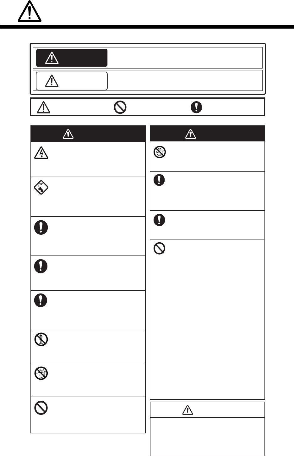
SAFETY INSTRUCTIONS
Indicates a potentially hazardous situation which, if not avoided,
could result in death or serious injury.
Indicates a potentially hazardous situation which, if not avoided,
could result in minor or moderate injury.
The operator must read the safety instructions before attempting to operate the equipment.
Warning, Caution Prohibitive Action Mandatory Action
WARNING
CAUTION
WARNING
Do not open the equipment.
The equipment uses high voltage that
can cause electrical shock. Refer any
repair work to a qualified technician.
Before turning on the radar, be sure
no one is near the antenna.
Prevent the potential risk of being
struck by the rotating antenna, which
can result in serious injury or death.
If water leaks into the equipment or
something is dropped into the
equipment, immediately turn off the
power at the switchboard.
Fire or electrical shock can result.
If the equipment is giving off smoke
or fire, immediately turn off the
power at the switchboard.
Fire or electrical shock can result.
If you feel the equipment is acting
abnormally or giving off strange
noises, immediately turn off the
power at the switchboard and
contact a service technician.
Do not disassemble or modify the
equipment.
Fire, electrical shock or serious injury
can result.
Make sure no rain or water splash
leaks into the equipment.
Fire or electrical shock can result if
water leaks into the equipment.
Do not place liquid-filled containers
on or near the equipment.
Fire or electrical shock can result if a
liquid spills into the equipment.
Do not operate the equipment with
wet hands.
Electrical shock can result.
Keep objects away from the antenna
unit, so as not to impede rotation of
the antenna.
Fire, electrical shock or serious injury
can result.
Use the proper fuse.
Use of the wrong fuse can cause fire or
electrical shock.
The data from AIS are intended for
reference purposes only.
Check all available navigation aids to
determine target movement.
Do not depend on one navigation
device for the navigation of the ship.
The navigator must check all aids
available to confirm position.
- The TT (Target Tracking) automatically
tracks an automatically or manually
acquired radar target and calculates its
course and speed, indicating them with
a vector. Since the data generated by
the TT depends on the selected radar
targets, the radar must be optimally
tuned for use with the TT, to ensure
required targets will not be lost or
unnecessary targets like sea returns
and noise will not be acquired and
tracked.
- A target is not always a landmass,
reef, ship, but can also be returns from
the sea surface and from clutter. As
the level of clutter changes with the
environment, the operator must
correctly adjust the sea and rain clutter
controls and the gain control so that
the target echoes do not disappear
from the radar screen.
WARNING WARNING
CAUTION

SAFETY INSTRUCTIONS
iii
The TT tracks and plots the movement of
up to 100 radar targets and fully complies
with IMO standards for TT.
Tracking accuracy is affected by the
following:
▪ Tracking accuracy is affected by course
change. One to two minutes is required to
restore vectors to full accuracy after an
abrupt course change. (The actual amount
depends on gyrocompass specifications.)
- Echo intensity
- Radar transmission pulse width
- Radar bearing error
- Gyrocompass error
- Course change (own ship and target)
▪ The amount of tracking delay is inversely
proportional to the relative speed of the
target. Delay is approx. 15-30 seconds for
the higher relative speed; approx. 30-60
seconds for the lower relative speed. The
following factors can affect accuracy:
The data generated by TT and AIS are
intended for reference only.
Refer to official nautical charts for detailed
and up-to-date information.
CAUTION

iv
TABLE OF CONTENTS
FOREWORD .................................................................................................................viii
SYSTEM CONFIGURATION ..........................................................................................ix
1. OPERATION ..........................................................................................................1-1
1.1 Controls...................................................................................................................... 1-1
1.2 How to Turn the Radar On/Off ................................................................................... 1-1
1.3 How to Transmit ......................................................................................................... 1-2
1.4 Radar Display Indications .......................................................................................... 1-2
1.5 Menu Operation ......................................................................................................... 1-4
1.5.1 How to operate the radar from the icons........................................................ 1-4
1.5.2 Menu window ................................................................................................. 1-5
1.5.3 How to show the hidden icons ....................................................................... 1-5
1.5.4 List windows................................................................................................... 1-6
1.6 How to Adjust Display Brilliance, Panel Dimmer ....................................................... 1-6
1.6.1 Display brilliance ............................................................................................ 1-6
1.6.2 Panel dimmer................................................................................................. 1-7
1.6.3 Brilliance Sets ................................................................................................ 1-7
1.7 Color Scheme ............................................................................................................ 1-9
1.8 Tuning ......................................................................................................................1-11
1.8.1 How to select the tuning method.................................................................. 1-11
1.8.2 Automatic tuning .......................................................................................... 1-11
1.8.3 Manual tuning............................................................................................... 1-11
1.8.4 How to initialize tuning ................................................................................. 1-11
1.9 Echo Area ................................................................................................................ 1-12
1.10 Operation Modes...................................................................................................... 1-12
1.10.1 How to select an operation mode................................................................. 1-12
1.10.2 Orientation mode.......................................................................................... 1-13
1.10.3 How to select an orientation mode............................................................... 1-14
1.10.4 How to change orientation mode presets..................................................... 1-15
1.11 How to Select the Range Scale ............................................................................... 1-15
1.12 Pulse width............................................................................................................... 1-17
1.12.1 How to change a pulse width ....................................................................... 1-17
1.12.2 How to select a pulse width.......................................................................... 1-18
1.13 How to Adjust the Gain (sensitivity) ......................................................................... 1-18
1.14 How to Reduce the Sea Clutter................................................................................ 1-19
1.15 How to Reduce the Rain Clutter............................................................................... 1-20
1.16 Cursor ......................................................................................................................1-20
1.17 FTC (Fast Time Constant) ....................................................................................... 1-21
1.18 How to Measure the Range to a Target (VRM)........................................................ 1-21
1.19 How to Measure the Bearing to a Target (EBL) ....................................................... 1-22
1.20 Offset EBL................................................................................................................ 1-23
1.20.1 How to measure the range and bearing between two targets...................... 1-23
1.20.2 Collision assessment by offset EBL............................................................. 1-25
1.20.3 Point of reference for origin point of offset EBL ........................................... 1-26
1.21 How to Off-center the Display .................................................................................. 1-27
1.22 Interference Rejecter................................................................................................ 1-28
1.23 Echo Stretch............................................................................................................. 1-28
1.24 Echo Averaging........................................................................................................ 1-29
1.25 Target Trails ............................................................................................................. 1-29
1.25.1 How to start, stop the trails........................................................................... 1-29
1.25.2 [TRAIL] menu............................................................................................... 1-30
1.25.3 Trail mode .................................................................................................... 1-30
TABLE OF CONTENTS
v
1.25.4 Trail level ......................................................................................................1-31
1.25.5 Trail time.......................................................................................................1-31
1.25.6 Own ship trail................................................................................................1-31
1.25.7 Trail color modes..........................................................................................1-32
1.26 Target Alarm.............................................................................................................1-32
1.26.1 How to set a target alarm .............................................................................1-32
1.26.2 How to select the alarm type ........................................................................1-33
1.26.3 How to select the target strength which triggers a target alarm ...................1-34
1.26.4 How to acknowledge the target alarm ..........................................................1-34
1.26.5 How to sleep a target alarm temporarily.......................................................1-34
1.26.6 How to delete a target alarm ........................................................................1-34
1.27 Nav Lines..................................................................................................................1-35
1.28 Alarms, Error Messages...........................................................................................1-36
1.28.1 Alarm indication............................................................................................1-36
1.28.2 Alarm description..........................................................................................1-37
1.28.3 Alarm summary ............................................................................................1-38
1.28.4 Alarm list/history ...........................................................................................1-38
1.28.5 Depth alarm..................................................................................................1-39
1.28.6 ROT alarm....................................................................................................1-39
1.29 Docking Mode...........................................................................................................1-39
1.29.1 How to activate the docking mode ...............................................................1-40
1.29.2 How to show or hide the docking information display ..................................1-40
1.29.3 Wind speed and direction.............................................................................1-40
1.29.4 Depth data....................................................................................................1-41
1.29.5 Depth graph..................................................................................................1-42
1.29.6 Speed and movement indications ................................................................1-42
1.30 How to Predict Own Ship’s Position .........................................................................1-43
1.31 How to Program Function Keys (F1 and F2)............................................................1-44
1.32 Markers.....................................................................................................................1-46
1.32.1 [MARK] menu ...............................................................................................1-46
1.32.2 Heading line .................................................................................................1-46
1.32.3 Stern mark....................................................................................................1-47
1.32.4 North mark....................................................................................................1-47
1.32.5 Own ship mark .............................................................................................1-47
1.32.6 Barge mark...................................................................................................1-48
1.33 NAV Data..................................................................................................................1-51
1.33.1 How to show ship’s position or speed and depth alternately........................1-51
1.33.2 How to show wind data or date alternately...................................................1-53
1.33.3 Time to the cursor position ...........................................................................1-54
1.33.4 Cursor position .............................................................................................1-54
1.33.5 ROT, Rudder and Autopilots Graphs ...........................................................1-54
1.34 Customized Menus...................................................................................................1-55
1.35 SD Cards..................................................................................................................1-57
1.35.1 About the SD cards ......................................................................................1-57
1.35.2 How to save and replay the data..................................................................1-58
1.36 How to Set Menu and Icon Behavior........................................................................1-59
1.36.1 Auto closing of menu window.......................................................................1-59
1.36.2 Icons.............................................................................................................1-60
1.37 Other Features .........................................................................................................1-61
1.37.1 Guidance box (Help function).......................................................................1-61
1.37.2 Menu transparency.......................................................................................1-61
1.37.3 Display capture.............................................................................................1-62
1.37.4 How to customize the operation ...................................................................1-64
1.37.5 Transmit time................................................................................................1-65
TABLE OF CONTENTS
vi
2. TARGET TRACKING (TT) .....................................................................................2-1
2.1 TT Display On/Off ...................................................................................................... 2-1
2.2 How to Acquire and Track Targets............................................................................. 2-3
2.3 Manual Acquisition ..................................................................................................... 2-3
2.4 Automatic Acquisition................................................................................................. 2-4
2.4.1 How to set an acquisition zone ...................................................................... 2-4
2.4.2 How to sleep an acquisition zone................................................................... 2-4
2.4.3 How to delete an acquisition zone ................................................................. 2-4
2.4.4 Acquisition zone reference.............................................................................2-5
2.5 How to Stop Tracking a Target .................................................................................. 2-5
2.6 TT Symbol Attributes.................................................................................................. 2-6
2.6.1 TT symbol brilliance ....................................................................................... 2-6
2.6.2 TT symbol color.............................................................................................. 2-6
2.7 Lost Target .................................................................................................................2-7
2.7.1 Lost target filter .............................................................................................. 2-7
2.7.2 How to acknowledge a lost target .................................................................. 2-7
2.8 TT Data ......................................................................................................................2-8
2.9 TT List ........................................................................................................................ 2-9
2.10 Vector Modes ...........................................................................................................2-10
2.10.1 Description of vectors................................................................................... 2-10
2.10.2 Vector mode and length............................................................................... 2-10
2.11 Past Position Display ............................................................................................... 2-11
2.11.1 How to select the dot number and interval of the past position.................... 2-11
2.11.2 Past position display mode .......................................................................... 2-11
2.12 CPA/TCPA Alarm..................................................................................................... 2-12
3. AIS OPERATION ...................................................................................................3-1
3.1 AIS Display On/Off ..................................................................................................... 3-1
3.2 AIS Display Filter........................................................................................................ 3-3
3.3 How to Activate Targets ............................................................................................. 3-4
3.3.1 How to activate specific targets manually ...................................................... 3-4
3.3.2 How to activate all targets.............................................................................. 3-4
3.4 How to Sleep Targets................................................................................................. 3-5
3.4.1 How to sleep an individual target ................................................................... 3-5
3.4.2 How to sleep all targets.................................................................................. 3-5
3.5 AIS Symbol Attributes ................................................................................................ 3-5
3.5.1 AIS symbol brilliance...................................................................................... 3-5
3.5.2 AIS symbol size and color.............................................................................. 3-5
3.6 Past Position Display ................................................................................................. 3-6
3.6.1 How to select the number and interval of the past position............................ 3-6
3.7 Lost Target .................................................................................................................3-7
3.7.1 Lost target filter .............................................................................................. 3-7
3.7.2 How to acknowledge a lost target .................................................................. 3-7
3.8 ROT Setting ............................................................................................................... 3-8
3.9 CPA/TCPA Alarm....................................................................................................... 3-8
3.10 Automatic Target Activation ....................................................................................... 3-9
3.11 AIS Target Data ....................................................................................................... 3-10
3.12 AIS List..................................................................................................................... 3-11
4. RADAR MAP..........................................................................................................4-1
4.1 What is a Radar Map? ............................................................................................... 4-1
4.2 [MARK] icon ............................................................................................................... 4-1
4.3 How to Enter Marks, Lines ......................................................................................... 4-2
4.3.1 How to enter a mark, line with at the cursor position ..................................... 4-2
4.3.2 How to enter a mark by latitude and longitude position input......................... 4-3
4.3.3 How to enter a mark at current position ......................................................... 4-3
TABLE OF CONTENTS
vii
4.4 Mark/Line information.................................................................................................4-3
4.5 How to Show, Hide Marks on the Screen...................................................................4-4
4.6 How to Delete Marks, Lines........................................................................................4-4
4.7 How to Align the Radar Map.......................................................................................4-5
5. MAINTENANCE, TROUBLESHOOTING ..............................................................5-1
5.1 Preventive Maintenance.............................................................................................5-2
5.2 Parts Replacement.....................................................................................................5-2
5.3 Diagnostic Test...........................................................................................................5-3
5.3.1 Self Test .........................................................................................................5-3
5.3.2 NMEA sentences checks ...............................................................................5-3
5.4 Easy Troubleshooting.................................................................................................5-4
5.5 Advanced Troubleshooting.........................................................................................5-5
APPENDIX 1 RADIO REGULATORY INFORMATION ............................................AP-1
APPENDIX 2 MENU TREE .......................................................................................AP-2
APPENDIX 3 DIGITAL INTERFACE (IEC61162-1)..................................................AP-6
SPECIFICATIONS ..................................................................................................... SP-1
INDEX ......................................................................................................................... IN-1

viii
FOREWORD
A Word to the Owner of the FR-1908V-BB Radar
Congratulations on your choice of the FR-1908V-BB Radar.
Please carefully read the safety information and operating instructions set forth in this manual
before attempting to operate the equipment and conduct any maintenance. Your radar set will
perform to the utmost of its ability only if it is operated and maintained in accordance with the
correct procedures.
Features
The FR-1908V-BB consists of an antenna unit, processor unit, and control unit and is designed to
meet the requirements of navigation radar used on inland waterways. Radar targets are displayed
on a 19-inch high resolution display, in a single color or gradations of green or cyan according to
echo strength. Following are the main features.
• Displays inland AIS targets
• Easy switching between River and Sea modes
• Automatic capture of the radar display
• Alarm history with Alarm log
• Graph displays: ROT, Rudder and AutoPilot
• TT (Track target) function to watch other ships’ movement
• Large capacity memory - Mark/Line: max. 5,000 points, TT: 100 targets, AIS: 300 targets
Program No.
0359451-01.**
** denotes minor modifications.
ix
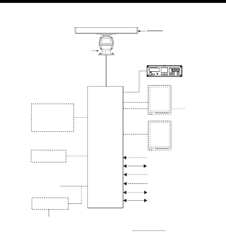
SYSTEM CONFIGURATION
ANTENNA UNIT
Category of Units
Antenna Unit: Exposed to the weather
All other units: Protected from the weather
Radiator
XN20AF
XN24AF
24 VDC
Rectifier
RU-1746B-2
100/110/115//220/230 VAC
1
φ
, 50/60 Hz
RSB-120-102
(26 rpm)
PROCESSOR
UNIT
RPU-026
Sub Display NMEA1 (HEADING SENSOR)
IEC61162-2
NMEA2 (AIS)
IEC61162-2
NMEA3 (NAV EQUIPMENT)
IEC61162-1
NMEA4 (Doppler)
IEC61162-1
NMEA5 (Alarm INS)
IEC61162-1
NMEA6 (ECDIS (TTM))
IEC61162-1
Control Unit
RCU-032
-ROT Sensor
(Analog/Alarm)
-Auto Pilot
(Analog/Follow-up)
-Rudder (Analog)
RW-0013
USB
DVI
RGB External Monitor
(VDR)
24 VDC
External Monitor
(MU-190V)
SYSTEM CONFIGURATION
x
This page is intentionally left blank.
1-1
1. OPERATION
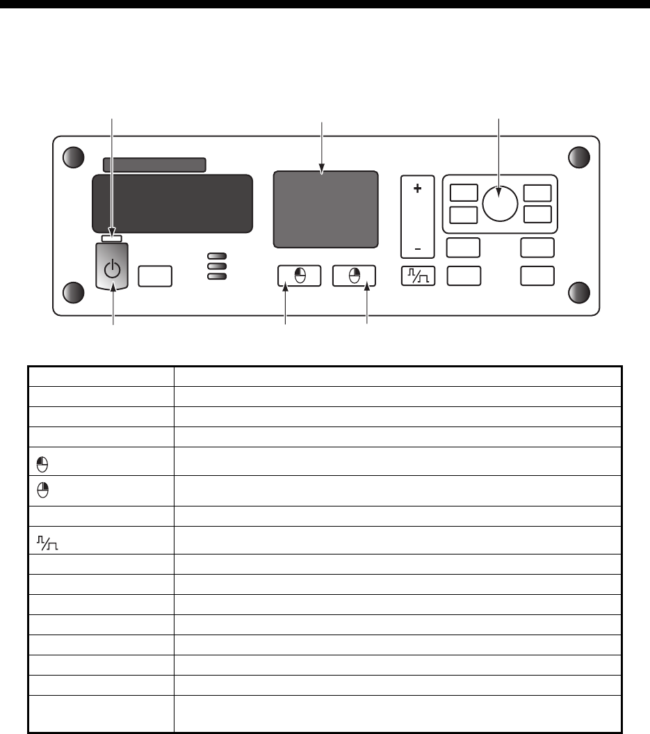
1.1 Controls
1.2 How to Turn the Radar On/Off
1. Open the cover at the bottom left section on the control unit. Press the Power key
to turn the radar on.
2. Press the Power key on the control unit to turn off the power.
Control Function
Power key Turn On/Off power. Power lamp lights when the power is turned on.
STBY/TX Switch between stand-by and transmission.
Touch pad Move the selection or the cursor.
Left-click
Right-click
RANGE Select display range.
Select the pulse width.
EBL Display/Hide EBL (Electronic bearing line).
VRM Display/Hide VRM (Variable range marker).
MENU Display/Hide Menu window.
BRILL Move the cursor on the [BRL] (brill) icon.
OFF CENTER Off-center own ship position.
HL OFF Hide the heading line temporarily.
F1, F2 Execute menu short cut assigned.
Setting knob Operate EBL, VRM, Brilliance.
Select the menu item.
PUSH TO SELECT
EBL
MENU
VRM
BRILL
F1
F2
OFF
CENTER
HL
OFF
RANGE
STBY
TX
ADJUST
Power key
Power lamp Touch pad Setting knob
Left button Right button
1. OPERATION
1-2
1.3 How to Transmit
To transmit, press the STBY/TX key while [STBY] is displayed. Radar echoes are
displayed on the screen with the previously used settings of range.
Each press of the STBY/TX key switches between stand-by and transmit (You can
also switch between stand-by and transmission by clicking the [STBY/TX] indication.).
The antenna is stopped in stand-by, and rotates in transmission.
The magnetron in the antenna unit generates the radar pulses and decays over time.
To extend the life of the magnetron, keep the radar in stand-by when its use is not
required.
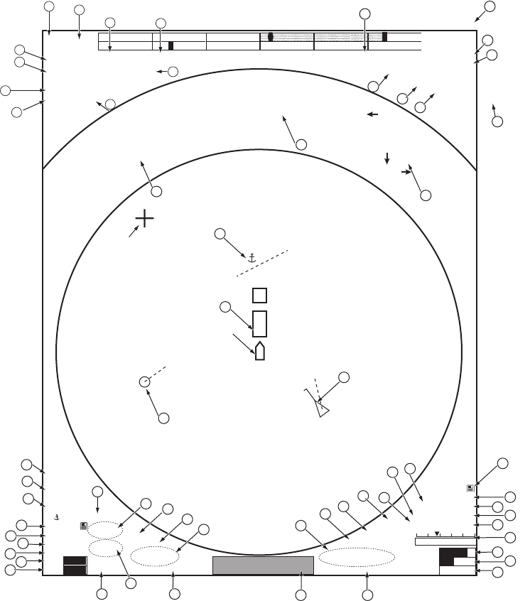
1.4 Radar Display Indications
The illustration below shows all the icons and symbols (both in the [RIVER] and [SEA]
modes) that may appear on the display. Some icons or symbols may not be shown
depending on the display mode.
Radar display example
10.4m/s
Front 10.4m
Aft 13.7m4.8
kn
4.8
kn
4.8
kn
SEA ROT
RUDDER
8 /2 km
HEAD- UP
►
STBY
►
OFFCENT OFF
HDG 123.4°
ALARM
►
ALARM
ACK
M1
MENU
BARGE ON
2WHT
►
MARK ON
CYA
►
DOCK ON
BRL2-3
►
ECHO
AZ1
►
AZ2
►
ALR1
►
ALR2
►
HL OFF
TT
ON
►
LIST
EBL1
123.4°
>
EBL2
82.9°
NAV
0.160
T
T
NM
AIS
FIL
►
TUNE
VRM1
1.567
VRM2
0.160
NAV
0.160
NM
LIST
►
NM
NM
MAN
MAN
MAN
AUTO
GAIN
STC
RAIN
75
40
FTC 1
IR 1
ES 2
EAV 3
TRAIL
►
2.50sec
00m03s
REL
ON
CUSTOM3-4
►
OS POSN N 34° 40.0000′
E 135° 20.0000′
UTC
CAPT
±300 º/m
±180 º
AUTO
SPD BT GPS-F
►
DPT AFT
►
CURSOR TTG
6.34km / 300.3°T
WIND
6.7 kn/h
123.4 m
02m45s
10.4 m/s
20-SEP-2012
23:59
GUIDANCE BOXGUIDANCE BOX
12
3
5
7
6
4
8
9
10
11
12
13
14
15
16
17
19
18
22
21
24
26
25
32
29
33
34
36
27
28
23
31
30 37
41
40
38
42
39
44
48
53
52
51
49
50
47
54
56
57
58
59
35
43
45
46
55
GRN
B-IN BLK
OUT D-GRN
MONI
PANL
50
15
Own ship
20
Cursor
*3
17

1. OPERATION
1-3
*1: River mode only *2: Sea mode only *3: Off by default
No. Icon/Symbol No. Icon/Symbol
1 Operation mode 2 ROT/Rudder graph
3 Range/Range ring interval 4 Orientation mode
5 Standby/Transmit 6 Off-center
7 Generated alarm 8 Alarm acknowledge
9 Heading 10 Pulse width
11*3Own ship position (Lat/Lon) 12 Capture
13 Ship speed 14 Depth
15 Time to go to cursor posi-
tion
16 Cursor position
17 Wind speed or Date/Time*318 Menu
19*1Barge Mark 20*1Mark
21 Brilliance set 22 Echo color
23 Background color (effective
display area)
24 Background color (outside
effective display area)
25 Monitor brill 26 Panel dimmer
27 Docking mode 28*2Acquisition zone 1, 2
29*2Target alarm 1, 2 30 Heading line Off
31*2Target tracking 32*2TT (Target tracking) list
33 EBL 1, 2 34 Nav line (port)
35 Guidance box 36 VRM 1, 2
37 Nav line (starboard) 38 AIS list
39 AIS 40 Trail elapsed time
41 Trail time 42 Trail mode (Relative or True)
43 Trail 44 Custom setting name
45 FTC 46 Interference rejection
47 Echo stretch 48 Echo average
49 Tuning 50 Gain
51 STC 52 Rain
53 Wind speed 54 Dual depth
55 Ship’s speed and move-
ment at fore, midpoint and
aft
56 Mark, Line
57*1Barge 58*1TT symbol
59*2AIS symbol
1. OPERATION
1-4
1.5 Menu Operation
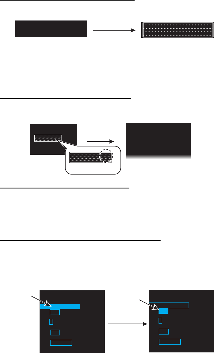
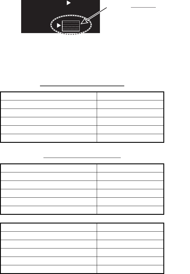
1.5.1 How to operate the radar from the icons
How to select the menu icon on the screen
Use the touch pad to select an icon. The icon is highlighted when correctly selected.
Operations available with the left button
• Open the main menu when the [MENU] icon is selected (see paragraph 1.5.2).
• Select options related to the selected icon cyclically.
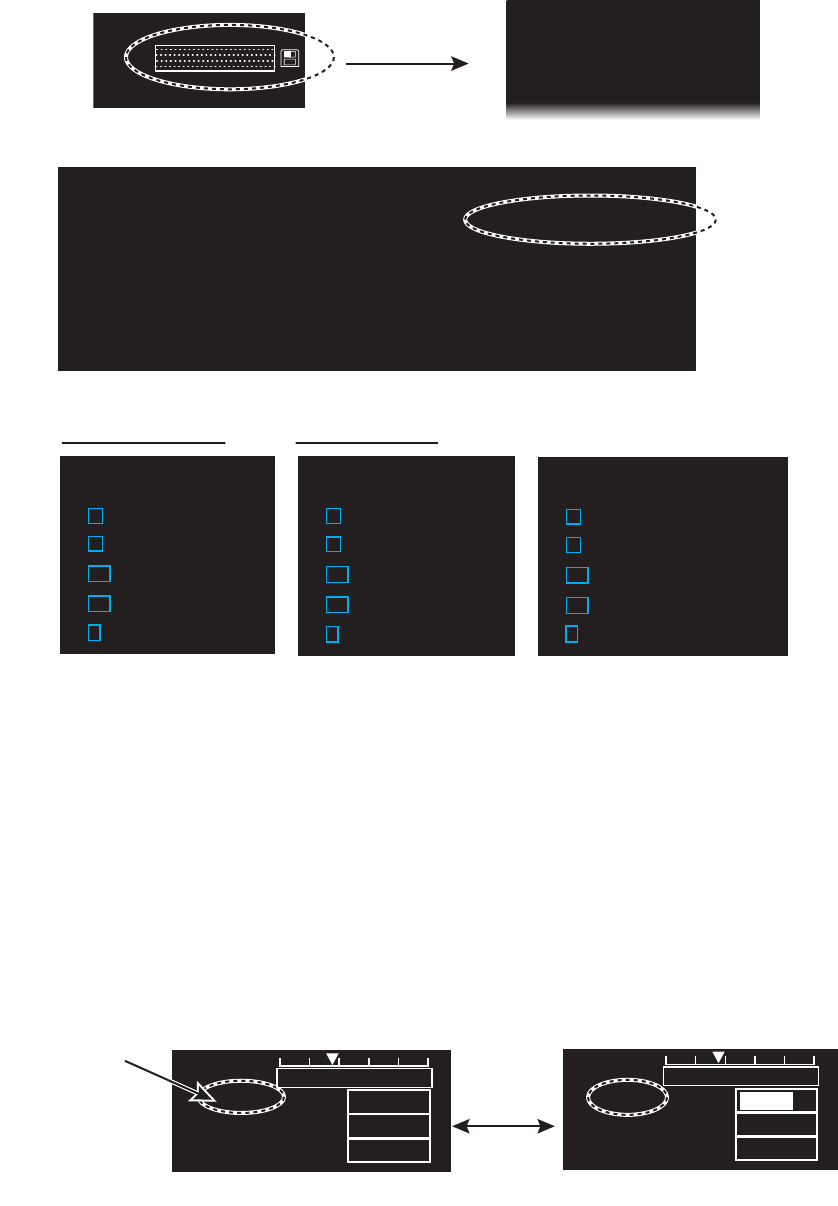
Operations available with the right button
Opens the sub menu window for the menu icon with the option mark (triangle).
Operation available with the setting knob
• Rotation: Change the setting value on the setting box (clockwise to decrease the
value, counterclockwise to increase the value).
• Press: Move the cursor on the setting box respectively among [GAIN], [STC] and
[RAIN].
How to select the menu items on the menu window
1. Use the touch pad to select the menu item. The selected menu item is enclosed
with a rectangle.
2. Use the touch pad to select an option. The selected option is enclosed with a
rectangle.
Click outside the menu window to close the menu window.
Put the cursor
on an icon
Highlighted
HEAD-UP ► HEAD-UP ►HEAD-UP ►HEAD-UP ►
Right-click
Selected menu
Sub menu
ECHO
B-IN
OUT
AZ1
AZ2
ALR1
ALR2
GRN
BLK
D GRN
BRL 2-3 ►
BRL 2-3 ►
Option mark
BRL 2-3 ►
BRL 2-3 ►
[BRILL MENU]
1 BACK
2 [EDIT]
3 [PRESET]
Menu
options
[TRAIL]
1 BACK
2 TRAIL MODE
REL /TRUE
3 TRAIL LEVEL
1 /2/3/4
4 OS TRAIL
OFF/1/2
5 TRAIL COLOR OPTION
DEFAULT/USER
Click
[TRAIL]
1 BACK
2 TRAIL MODE
REL /TRUE
3 TRAIL LEVEL
1 /2/3/4
4 OS TRAIL
OFF/1/2
5 TRAIL COLOR OPTION
DEFAULT/USER
Menu
items
1. OPERATION
1-5
Mouse operation
A mouse can be connected to the processor unit to control radar functions. The table
below compares operation with the control unit and mouse.
Note: Connect the USB mouse to the processor unit directly. Do not use a USB hub
when connecting the USB mouse to the prosessor unit.
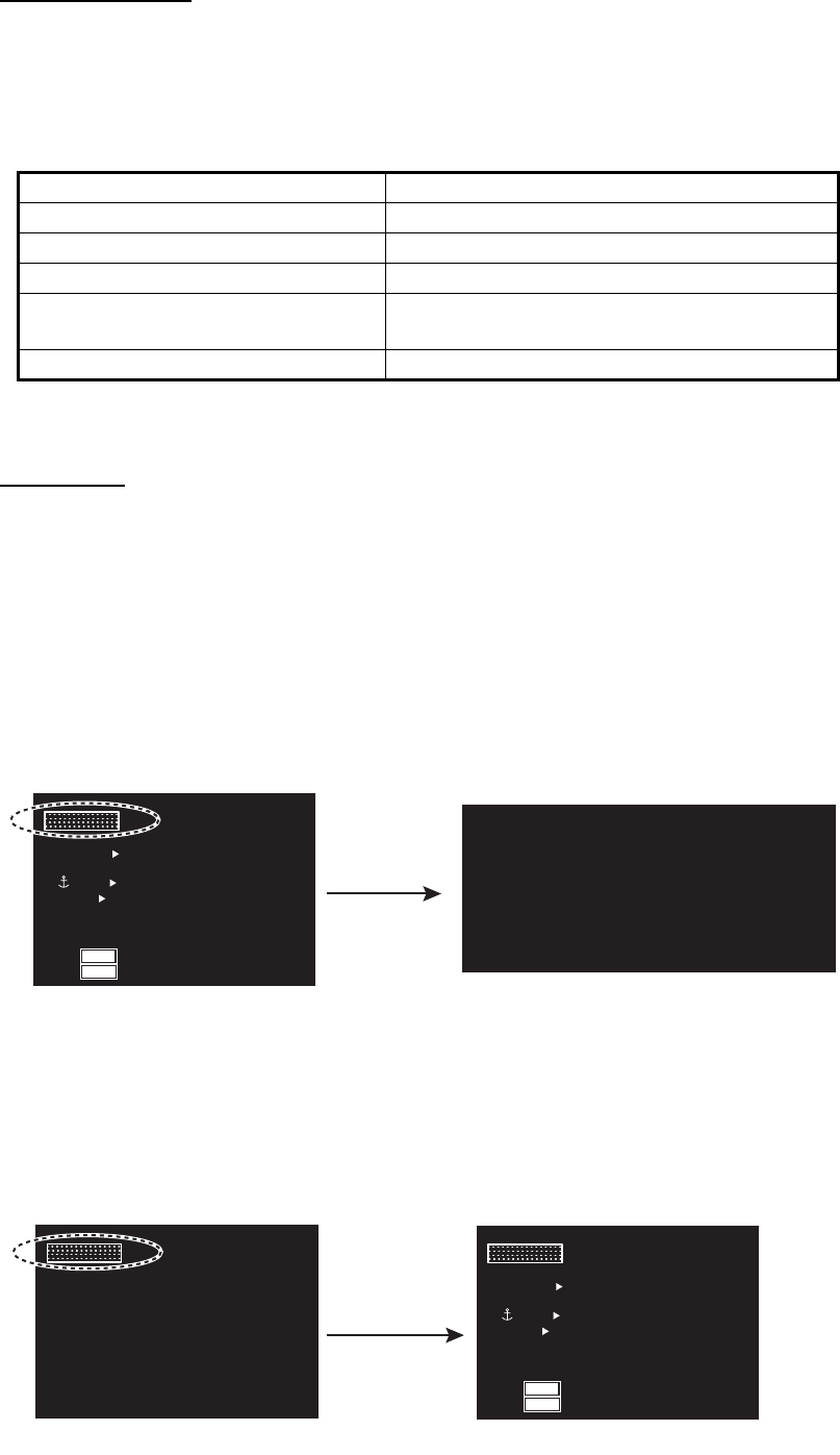
1.5.2 Menu window
Main menu
To open the main menu, put the cursor on the [MENU] icon.
Note: Hereafter, placement of the cursor and operation of the left button are omitted
in procedures done with icons. For example, the above sentence would be written as
"Click the [MENU] icon."
To close the main menu, left-click or right-click outside the menu window. Also, if no
operation for specified duration*, the main menu is closed automatically.
*: Sets the duration on the [AUTO-CLOSING TIME] menu.
1.5.3 How to show the hidden icons
If the radar can be set to hide some icons after a specified interval, click the [MENU]
icon to display the hidden icons.
Control unit Mouse
Cursor movement by touch pad Cursor movement by mouse operation
Left button press Left-click
Right button press Right-click
Setting knob rotation • Wheel rotation
• Cursor movement when selecting menus
Setting knob press Wheel press
Click
[MAIN MENU] for [RIVER] mode
BARGE ON
2WHT
ON
CYA DOCK OFF
BRL2-3
ECHO
B-IN
OUT
MONI
PANL
HL OFF
EBL1
123.4°
>
EBL2
82.9°
NAV
0.160
T
T
km
GRN
BLK
D-GRN
50
15
MARK
MARK
MENU
MENU
[MAIN MENU]
1 BACK
2 [ECHO]
3 [DISPLAY]
4 [MARK]
6 [RADAR MAP]
7 [NAV DATA]
8 [FILES]
9 [CAPTURE]
10 [CONFIGURATION]
(at the bottom left corner on the
screen in [RIVER] mode )
Click
Hidden icons appear.
BARGE ON
2WHT
ON
CYA DOCK OFF
BRL2-3
ECHO
B-IN
OUT
MONI
PANL
HL OFF
EBL1
123.4°
>
EBL2
82.9°
NAV
0.160
T
T
km
GRN
BLK
D-GRN
50
15
MARKMARK
MENUMENU
MENUMENU
1. OPERATION
1-6
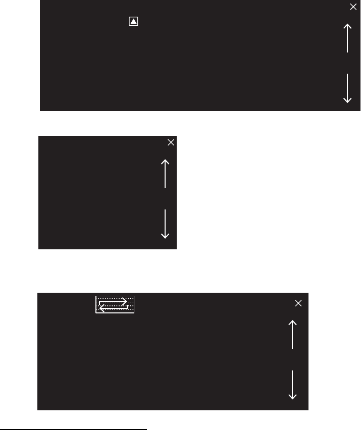
1.5.4 List windows
There are three list windows (TT, AIS and Alarm) and they provide information about
tracking targets, AIS targets and generated alarms.
• TT list: Click the [LIST] icon for TT at the bottom of the display to show the TT list.
• AIS list: Click the [LIST] icon for AIS at the bottom of the display to show the AIS list.
• Alarm list: Right-click the [ALARM] icon at the top left corner then click [3 ALARM
LIST/HISTORY] to show the Alarm list.
How to close a list window
Click the close button (×) at the top right corner of the list window. Alternately,
right-click or left-click outside the window.
1.6 How to Adjust Display Brilliance, Panel Dimmer
1.6.1 Display brilliance
You can adjust the display brilliance (setting range: 0 to 50) with the [MONI] icon. The
connection between the processor unit and the monitor unit MU-190RH with the USB
cable (supplied) is required. See the Operator’s manual of MU-190RH.
Note: This function is available when the following menus of MU-190RH are set as below:
• [AUTO DIMMER]: [OFF]
• [EXT BRILL CTRL]: [ON]
[TT LIST]
No. RANGE BEARING CPA TCPA
001 9. 60NM 058. 8°T 0. 00NM 00m00s
002 19. 2NM 059. 0°T 0. 00NM 00m00s
[AIS LIST] <SORT>NAME-UP 1/1
MMSI NAME
12XXXXXXXXX ABCXX
2345XXXXXXX AXX
[ALARM LIST] 1/1
ITEM TYPE DATE/TIME
ROT SENSOR ERROR
00:00:000000/00/00
AIS RECEIVE ERROR AIS WARNING 00:00:000000/00/00
1. OPERATION
1-7
1. Click the setting box for display brilliance at the bottom left corner of the screen.
2. Press the left button to decrease the brilliance; the right button to increase the
brilliance. With mouse connection, rotate the wheel or click the right or left button
to adjust the brilliance.
1.6.2 Panel dimmer
The backlighting for the keys on the control unit can be adjusted as follows:
1. Click the setting box for panel dimmer at the bottom left corner on the screen.
2. Press the left button to decrease the dimmer; the right button to increase the
dimmer. With mouse connection, rotate the wheel or click the right or left button
to adjust the panel dimmer.
1.6.3 Brilliance Sets
This radar provides customized sets of brilliance to match any ambient lighting
condition. Four sets of customized brilliance settings are available for four users each,
for a total of 16 sets.
When the radar is powered on, the display is shown with the maximum brilliance
setting. Select the appropriate brilliance, depending on the environment.
Setting box for
monitor brilliance
Left-click
or
Rotate the setting knob
counterclockwise
Increase the brilliance
Decrease the brilliance
Right-click
or
Rotate the setting
knob clockwise
ECHO
B-IN
OUT
MONI
PANL
HL OF
GRN
BLK
D-GRN
30
15
BRL2-3
MENU
ECHO
B-IN
OUT
MONI
PANL
HL OF
GRN
BLK
D-GRN
29
15
BRL2-3
MENU
ECHO
B-IN
OUT
MONI
PANL
HL OF
GRN
BLK
D-GRN
31
15
BRL2-3
ECHO
B-IN
OUT
MONI
PANL
HL OF
GRN
BLK
D-GRN
30
15
BRL2-3
Setting box for panel dimmer
Customized brilliance
settings 4 sets
USER 1
USER 2
USER 3
USER 4
16 sets
1. OPERATION
1-8
How to select a customized brilliance set
1. Click the [BRL] icon at the bottom left corner on the screen to show the [BRILL
MENU] window.
2. Click the user name and the required brilliance set.
3. Click outside the menu window to close the menu.
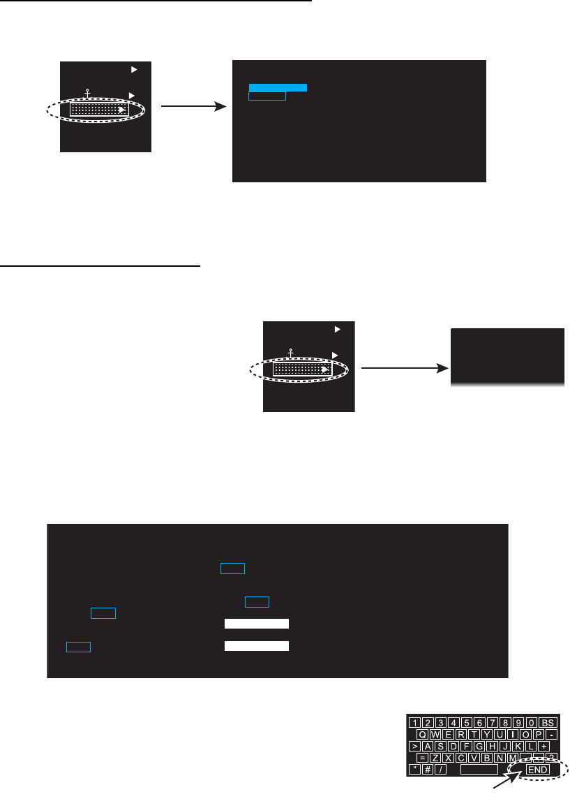
How to edit [BRILL MENU]
You can edit the menu contents for each brilliance set.
1. Right-click the [BRL] icon at
the bottom left corner on the
screen to show the [BRILL
MENU] window.
Note: The [BRL1-1] setting
is fixed as a default setting.
You can edit the setting, but
when the system is turned off, the default setting is restored. To save a custom
brilliance set, select a setting other than [BRL1-1].
2. Click [EDIT].
3. Click [USER NAME].
4. To edit the name, click the name column then enter the
name with the software keyboard. Click the [END]
button to finish.
• Change the digit: Rotate scrollwheel.
• Delete a character: Use the [BS] button on the
software keyboard.
5. Click [USER COMMENT] to edit. The editing procedure is the same as that for
[USER NAME]. Refer to step 4.
6. To edit the comment, click the respective BRL column then enter the comment
with the software keyboard. Click the [END] button to finish.
7. Click the menu item, [4 ECHO COLOR] to [11 BRILL DETAIL], to edit.
8. Set the option for each menu item as appropriate.
9. Click [SAVE & QUIT] to save the settings.
[BRL] icon
2WHT
ON
CYA D
O
ECHO
B-IN
OUT
GRN
BLK
D
-
GRN
MARK
MARK
BRL2-3
BRL2-3
1 BACK
2 USER-NAME1
BRL1-1/
BRL1-2/
BRL1-3/
BRL1-4
3 USER-NAME2
BRL2-1/
BRL2-2/
BRL2-3/
BRL2-4
4 USER-NAME3
BRL3-1/
BRL3-2/
BRL3-3/
BRL3-4
5 USER-NAME4
BRL4-1/
BRL4-2/
BRL4-3/
BRL4-4
[BRILL MENU]
Click
[BRILL MENU]
1 BACK
2 [EDIT]
3 [PRESET]
Right-click
[BRL] icon
2 WHT
ON
CYA D
O
ECHO
B-IN
OUT
GRN
BLK
D
-
GRN
MARK
MARK
BRL2-3
BRL2-3
1 BACK
2 USER NAME
USER NAME 1
3 USER COMMENT
BRL1-1
4 ECHO COLOR
YEL/GRN/WHT/AMB/
M-GRN/M-CYA
5 BACK COLOR (INSIDE)
BLK/D-BLU/L-BLU/
D-GRY
6 BACK COLOR (OUTSIDE)
BLK/D-BLU/L-BLU/
D-GRY/D-GRN
7 TRAIL COLOR
YEL/GRN/WHT/AMB/BLU
8 MONITOR BRILL
9 PANEL DIMMER
10 [COLOR DETAIL]
11 [BRILL DETAIL]
12 SAVE & QUIT
[EDIT]
[END] button
1. OPERATION
1-9
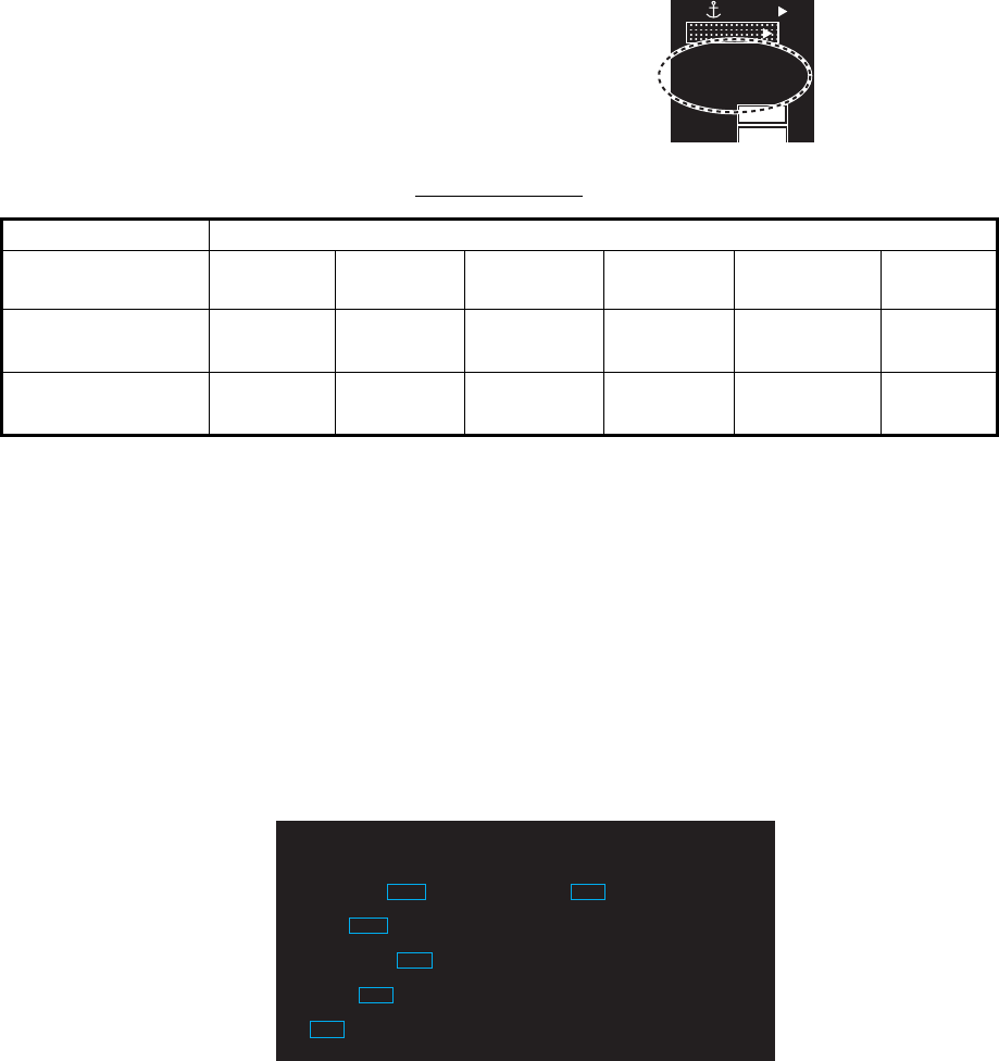
1.7 Color Scheme
You can select the color for echo and background
color (inside/outside) with the display icons.
Available colors
You can set the customized color for the following items on [COLOR DETAIL].
1. Right-click the [BRL] icon at the bottom left corner on the screen to show the
[BRILL MENU] window.
2. Click [EDIT].
3. Click [COLOR DETAIL].
4. Set the option for each menu item as appropriate.
5. Click [SAVE & QUIT] to save the settings.
Available options (Each color is selectable respectively)
[ECHO COLOR] YEL
(yellow)
GRN
(green)
WHT
(white)
AMB
(amber)
M-GRN* M-CYA*
[BACK COLOR
(INSIDE)]
BLK
(black)
D-BLU
(dark blue)
L-BLU
(light blue)
D-GRY
(dark gray)
——
[BACK COLOR
(OUTSIDE)]
BLK
(black)
D-BLU
(dark blue)
L-BLU
(light blue)
D-GRY
(dark gray)
D-GRN
(dark green)
—
• Echo color
• Back color
(effective display area)
• Back color
(outside effective
display area)
• Trail color
• Character color
• Fixed range ring color
• Gyro scale color
• EBL/VRM/NAV LINE color
• Alarm indication
• Cursor color
CYA D
O
ECHO
B-IN
OUT
MONI
PANL
H
GRN
BLK
D-GRN
50
15
MARK
BRL2-3
BRL2-3
Click the icon to
change the color.
1 BACK
2 CHARACTER
GRN/RED/WHT
3 FIXED RING
GRN/WHT
4 GYRO RING
L-BLU/RED/GRN/WHT
5 EBL/VRM/NAV LINE
L-BLU/GRN/WHT
6 ALARM
RED/WHT
7 CURSOR
GRN/WHT
[COLOR DETAIL]
1. OPERATION
1-10
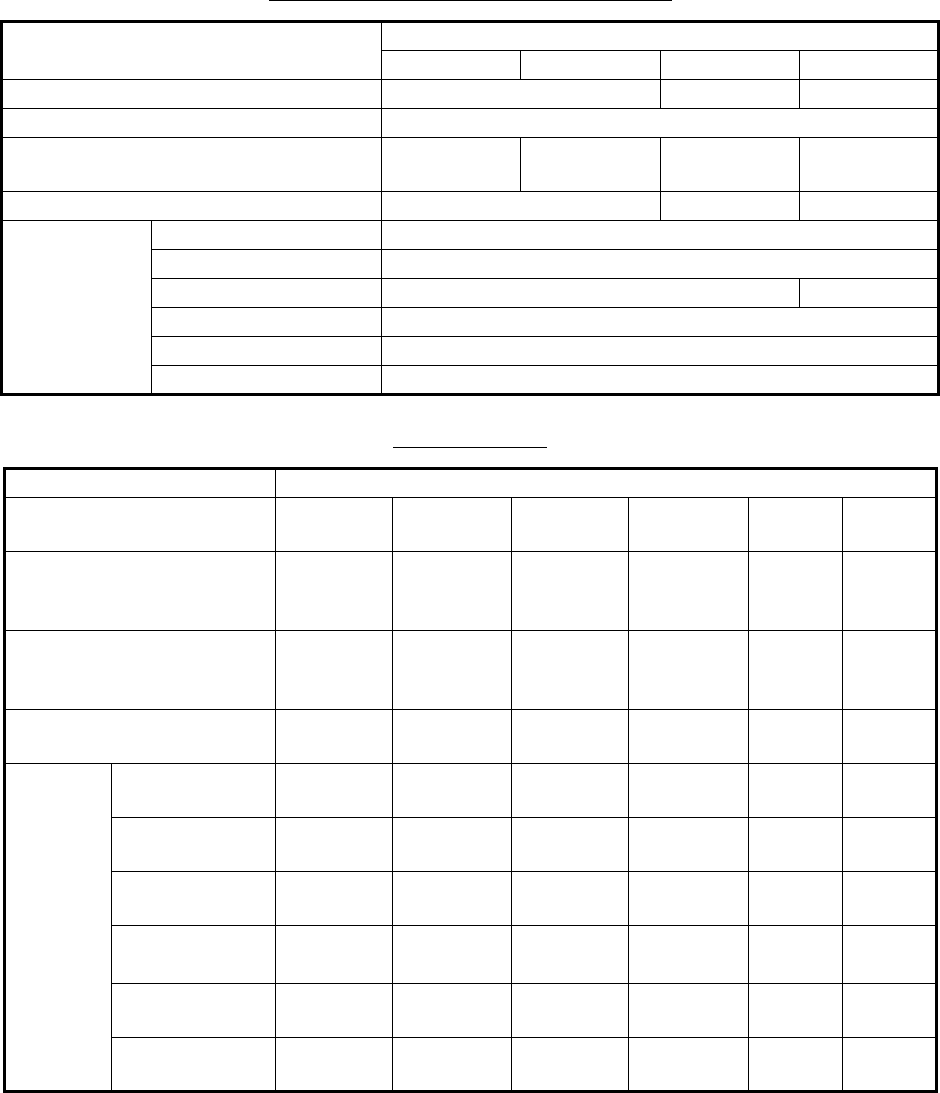
Default settings for [USER 1] to [USER 4]
Available colors
*: [M-GRN]: Multi-green (green gradation), for [SEA] mode only
[M-CYA]: Multi-cyan (cyan gradation), for [SEA] mode only
Available options (Each color is selectable)
[USER 1] [USER 2] [USER 3] [USER 4]
[ECHO COLOR] GRN (green) WHT (white) GRN (green)
[BACK COLOR (INSIDE)] BLK (black)
[BACK COLOR (OUTSIDE)] BLK (black) D-BLU
(dark blue)
D-GRY
(dark gray)
D-GRN
(dark green)
[TRAIL COLOR] GRN (green) WHT (white) GRN (green)
[COLOR
DETAIL]
[CHARACTER] WHT (white)
[FIXED RING] WHT (white)
[GYRO RING] GRN (green) WHT (white)
[EBL/VRM/NAV LINE] GRN (green)
[ALARM] RED
[CURSOR] GRN (green)
Available options (Each color is selectable)
[ECHO COLOR] YEL
(yellow)
GRN
(green)
WHT
(white)
AMB
(amber)
M-
GRN*
M-
CYA*
[BACK COLOR
(INSIDE)]
BLK
(black)
D-BLU
(dark blue)
L-BLU
(light
blue)
D-GRY
(dark gray)
——
[BACK COLOR
(OUTSIDE)]
BLK
(black)
D-BLU
(dark blue)
L-BLU
(light
blue)
D-GRY
(dark gray)
D-GRN
(dark
green)
—
[TRAIL COLOR] YEL
(yellow)
GRN
(green)
WHT
(white)
AMB
(amber)
BLU
(Blue)
—
[COLOR
DETAIL]
[CHARACTER] GRN
(green)
RED WHT
(white)
———
[FIXED RING] GRN
(green)
WHT
(white)
—— ——
[GYRO RING] L-BLU
(light blue)
RED GRN
(green)
WHT
(white)
——
[EBL/VRM/
NAV LINE]
L-BLU
(light blue)
GRN
(green)
WHT
(white)
———
[ALARM] RED WHT
(white)
—— ——
[CURSOR] GRN
(green)
WHT
(white)
—— ——
1. OPERATION
1-11
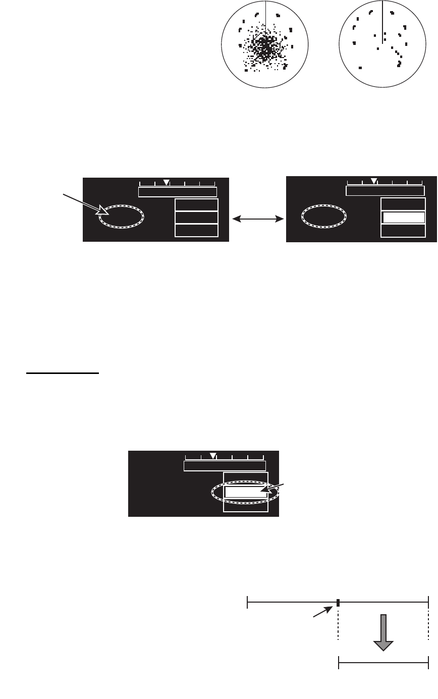
1.8 Tuning
1.8.1 How to select the tuning method
The tuning method, auto tuning or manual tuning, can be selected with the tuning icon
as follows.
Click the tuning icon ([AUTO] or [MAN]) at the bottom right corner on the screen to
switch between [AUTO] and [MAN].
1.8.2 Automatic tuning
Click the tuning icon to select [AUTO] referring to paragraph 1.8.1.
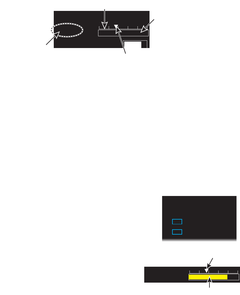
1.8.3 Manual tuning
1. Click the tuning icon to select [MAN] referring to paragraph 1.8.1.
2. Put the cursor on the tuning bar.
3. Rotate the setting knob to adjust the tuning. The best tuning point is where the bar
swings maximum. The triangle in the bar graph shows tuning level; not the tuning
condition.
1.8.4 How to initialize tuning
Automatic tuning is initialized during the installation.
However, if you feel that automatic tuning is not
working properly try re-initializing the tuning. Open
[MAIN MENU] then click [ECHO] to open [ECHO]
menu. Then click [TUNE INITIALIZE] to start the
initialization.
The tuning bar turns yellow and moves during
the initialization.
Note 1: The display may appear incorrect during
initialization, caused by changes in pulse or
tuning levels.
Note 2: The following operations cancel the initialization process.
• Change of range
• Go [STBY] mode
• Change of pulse width
NM MAN
AUTO
GAIN
75
EAV
3
00m03s
ON
TUNE
Put the cursor inside box
to adjust tuning, when
[MAN TUNE] is selected.
Tuning bar
Tuning level
Tuning icon
([AUTO] or [MAN])
[ECHO]
1 BACK
2 TUNE INITIALIZE
3 STC PRESET
OFF/ON
4 FTC PRESET
OFF/ON
AUTO TUNE
Tuning bar (yellow)
Tuning level moves during
initialization
1. OPERATION
1-12
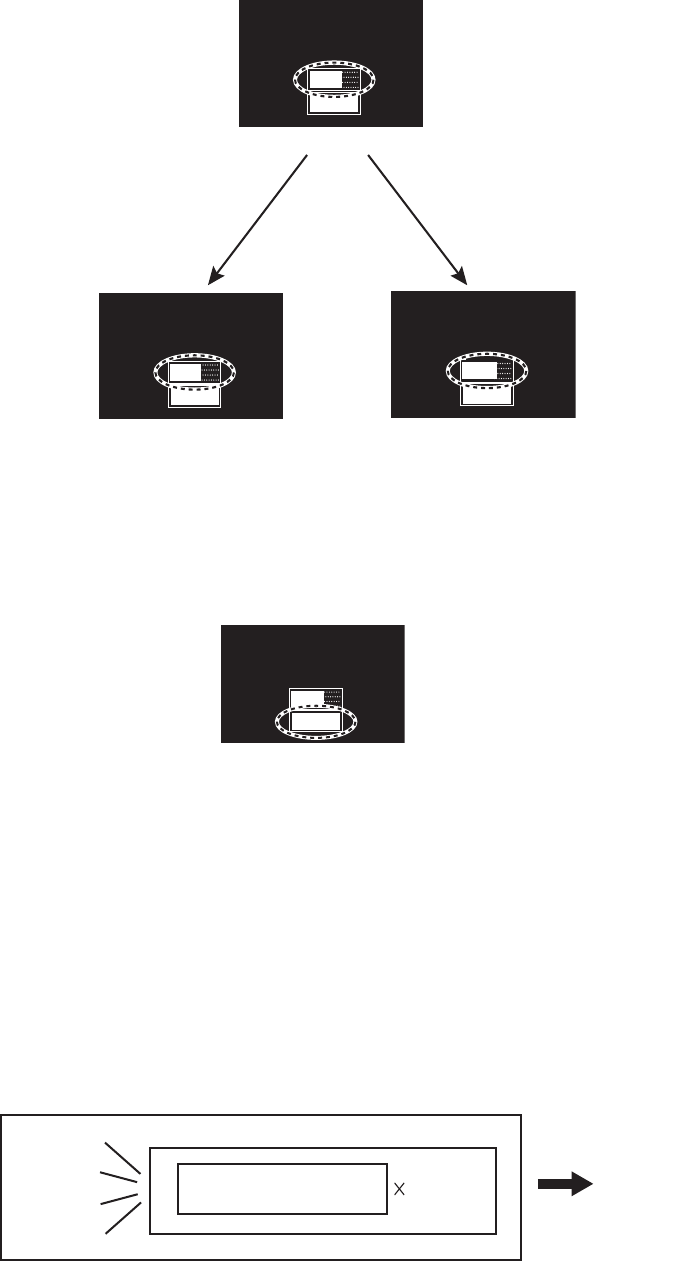
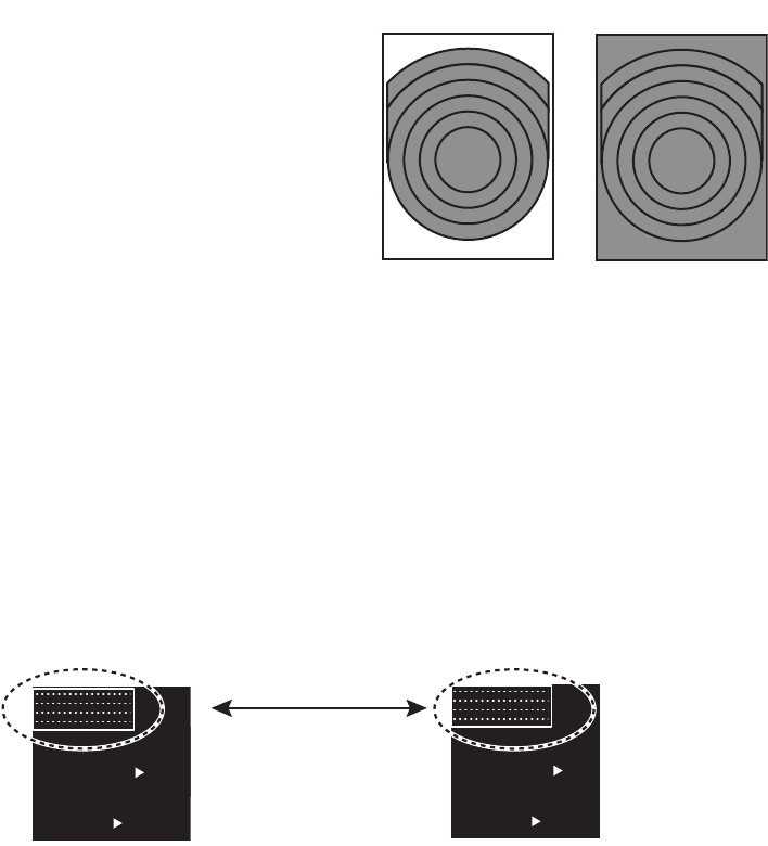
1.9 Echo Area
The echo display area can be selected for [CIRCLE] or [WIDE], in the [SEA] mode.
1. Open [MAIN MENU], click [DISPLAY].
2. Click [ECHO AREA] then select the
option.
[CIRCLE]: Echoes in the radar circle.
[WIDE]: Echoes in the whole of the
display
3. Click outside the menu window to close
the menu.
1.10 Operation Modes
This radar has two operating modes: river mode and sea mode.
• The river mode provides the radar display used at river.
• The sea mode provides the traditional radar display.
1.10.1 How to select an operation mode
Click the operation mode icon at the top left corner of the screen to select [RIVER] or
[SEA].
Note 1: To enable switching of the operation mode, the [OPERATION TYPE] setting,
in the [SERVICE MENU], must be set to [RIVER-SEA]. See your dealer.
Note 2: To change the operation mode ([RIVER] or [SEA]), go to [STBY] once to
select the operation mode then go to [TX] mode.
The following items are set according to the operation mode.
• Orientation mode
• Range
• Units
• Screen size (River mode: circle* only, Sea mode: circle* and wide*)
*: See section 1.9.
[CIRCLE] [WIDE]
Gray zone: Echo area
Click the operation
mode icon
SEA
RO
T
RUDDE
R
2/ 0.4
NM
HEAD-UP
STBY
OFFCENT
HDG
S
OFF
RIVER
RO
RUDDE
1.6/ 0.4
km
HEAD-UP
STBY
OFFCENT
HDG
S
OFF
1. OPERATION
1-13
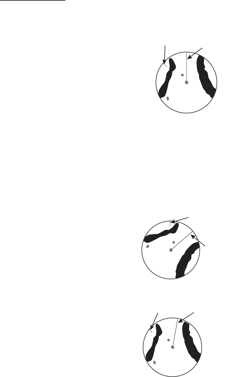
1.10.2 Orientation mode
Relative motion (RM)
In relative motion, own ship position is stationary on the screen to observe relative
motion of surrounding targets.
• HEAD UP
The head-up mode is a display in which the line
connecting own ship and the top of the display
indicates own ship's heading. The target pips
are painted at their measured distances and in
their directions relative to own ship's
heading.The short line on the bearing scale is
the north marker, which indicates heading
sensor north.
• HEAD UP (TB)
Radar echoes are shown in the same way as in the head-up mode. The difference
from normal head-up presentation lies in the orientation of the bearing scale. The
bearing scale rotates in accordance with the heading sensor signal, enabling you to
know own ship's heading at a glance.
This mode is available when the radar is interfaced with a gyro heading sensor. If
the gyro heading sensor fails, the bearing scale returns to the state of head-up
mode.
• STERN UP
A display without azimuth stabilization in which the line that connects the center with
the top of the display indicates your stern.
• NORTH UP
The north-up mode paints target pips at their
measured distances and in their true (heading
sensor) directions from own ship, north bearing
is fixed at the top of the screen. The heading
line changes its direction according to the
ship's heading. This mode requires heading
signal.
If the compass fails, the orientation mode
changes to head-up and the north marker
disappears.
• COURSE UP
The course-up mode is an azimuth stabilized
display in which a line connecting the center
with the top of the display indicates own ship's
intended course (namely, own ship's previous
heading just before this mode has been
selected).Target pips are painted at their
measured distances and in their directions
relative to the intended course, which is
maintained at the 0-degree position.
The heading line moves in accordance with
ship's yawing and course change.
North marker Heading
line
North mark
Heading
line
North mark Heading
line
1. OPERATION
1-14
True motion (TM)
• NORTH UP
Ground (or water mass) is stabilized with compass and speed inputs. Your ship and
other objects in motion move with their true courses and speed.
• COURSE UP
Own ship and other moving objects move in
accordance with their true courses and
speed. In ground stabilized TM, all fixed
targets, such as landmasses, appear as
stationary echoes. In the sea stabilized TM
without set and drift inputs, the landmass can
move on the screen.
Mode availability
: The necessary data to enable the operation mode.
1.10.3 How to select an orientation mode
Select the orientation mode icon then press the left button to select an orientation
mode.
Note: You can not set [HEAD-UP] to [OFF].
Orientation
mode
Data Availability
Heading L/L [RIVER] mode [SEA] mode
Head up RM Yes Yes
Head up RM (TB) No Yes
Stern up RM Yes Yes
North up RM No Yes
Course up RM No Yes
North up TM No Yes
Course up TM No Yes
North mark
Heading
line
HEAD-UPHEAD-UP
HU TB*HU TB*
STERN-UPSTERN-UP
NORTH-UP*NORTH-UP*
CU RM*CU RM*
NU TM*NU TM*
CU TM*CU TM*
Left-
click
Switches the orientation mode
(*: Sea mode only)
SEA
RO
T
RUDDE
R
6/ 1.5
NM
STBY
OFFCENT
HDG
L
OFF
HEAD-UP
HEAD-UP
Orientation icon
(at the top left corner on the screen)
1. OPERATION
1-15
1.10.4 How to change orientation mode presets
Seven orientation modes are available in the [SEA] mode, two orientation modes in
the [RIVER] mode. You can remove unnecessary modes from the Orientation icon as
follows.
1. Right-click the orientation icon to show the [ORIENTATION MODE] window.
2. Click the mode to set.
3. Click [ON] or [OFF]. Any mode set to [OFF] is removed from the Orientation icon.
Note: You can not set [HEAD-UP] to [OFF].
4. Click outside the menu window to close the menu.
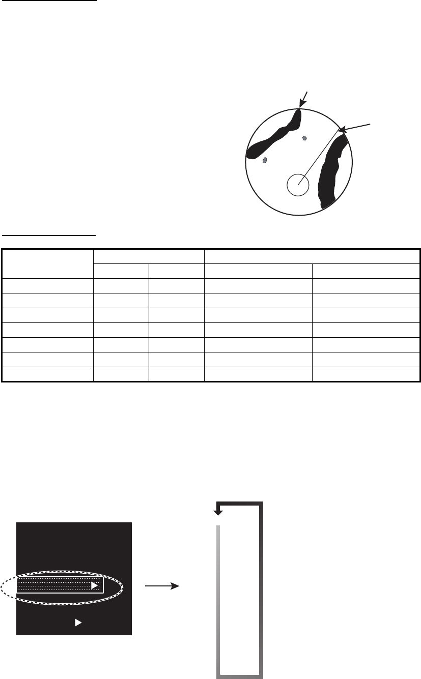
1.11 How to Select the Range Scale
The selected range scale, range ring interval
and pulse width are shown at the top left
corner on the screen. When a target of
interest comes closer, reduce the range
scale so that it appears in 50-90% of the
display radius.
The available units for range are NM, KM,
SM, and KYD. You can change the unit when
installed.
Left-click the range scale icon to decrease the range: right-click to increase the range.
Orientation icon
(at the top left corner on the screen)
Right-
click
SEA
ROT
RUDDER
4 /1
NM
HEAD-UP
S
TBY
OFFCENT
HDG
A
M1
OFF
[ORIENTATION MODE]
1 BACK
2 HEAD-UP
OFF/ON
3 HEAD-UP TB*
OFF/ON
4 STERN-UP
OFF/ON
5 NORTH-UP*
OFF/ON
6 COURSE-UP*
OFF/ON
7 NORTH-UP TM*
OFF/ON
8 COURSE-UP TM*
OFF/ON
*: [SEA] mode only
SEA
ROT
RUDDER
HEAD-UP
OFFCENT
HDG 123.4°
ALARM
ALARM
ACK
OFF
Range ring interval
Range scale
6/ 1.5
NM
6/ 1.5
NM
Right-click
Range scale selected
Left-click
Increase the range
Decrease the range
0.5/ 0.1
NM
0.75/ 0.25
NM
1/ 0.25
NM

1. OPERATION
1-16
Range for River mode
In River mode, the default unit is SM.
Range for Sea mode
In Sea mode, the default unit is NM.
Range (SM) Range ring interval (SM)
0.125 0.025
0.25 0.05
0.5 0.1
0.8 0.2
1.2 0.2
1.6 0.4
20.4
41
82
16 4
32 8
64 16
Range (NM) Range ring interval (NM)
0.125 0.025
0.25 0.05
0.5 0.1
0.75 0.25
10.25
1.5 0.25
20.4
30.5
41
61
82
12 2
16 4
24 4
32 8
48 8
64 16
1. OPERATION
1-17
1.12 Pulse width
The pulse width in use is displayed at the top left corner on the screen. The pulse
widths are set to each range scale and custom setup. Use a longer pulse width when
your purpose is long range detection. Use a shorter pulse width when the resolution
is important.
1.12.1 How to change a pulse width
The pulse width in use is displayed at the top left corner of the screen using the
indications shown in the table below.
Left-click the pulse icon to shorten the pulse width or right-click to lengthen the pulse
width.
Appropriate pulse widths are preset to individual range scales. If you are not satisfied
with the current pulse width settings, you may change them referring to
paragraph 1.12.2.
Pulse width for [RIVER] mode
Pulse width for [SEA] mode
Range (SM) Available pulse width
0.125/ 0.25/ 0.5/ 0.8/ 1.2 S
1.6/2 S/M1
4M1/M2
8/16 M2/L
32/64 L
Range (NM, SM) Available pulse width
0.125/ 0.25/ 0.5/ 0.75/ 1 S
1.5/ 2 S/M1
3/ 4 M1/M2
6/ 8/ 12/ 16 M2/L
24/ 32/ 48/ 64 L
Range (km, kyd) Available pulse width
0.125/ 0.25/ 0.5/ 0.75/ 1/ 1.5/ 2 S
3/ 4 S/M1
6/ 8 M1/M2
12/ 16/ 24/ 32 M2/L
48/ 64 L
STBY
OFFCENT
HDG
1
OFF
HEAD-UPHEAD
-
UP
M1
M1
Pulse
icon
Indication
[S]: Short pulse
[M1]: Medium pulse 1
[M2]: Medium pulse 2
[L]: Long pulse
1. OPERATION
1-18
1.12.2 How to select a pulse width
1. Right-click [CUSTOM] icon at the bottom right corner on the screen to show
[CUSTOM MENU].
2. Click [EDIT].
3. Click [PULSE WIDTH].
4. Click the range in use.
5. Click the desired pulse width.
6. Click outside the menu window to close the menu.
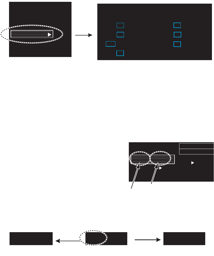
1.13 How to Adjust the Gain (sensitivity)
The gain functions to adjust the sensitivity of the receiver for the best reception. The
gain can be adjusted automatically or manually.
1. Click the gain mode icon at the bottom right corner on the screen to show [MAN]
or [AUTO] as appropriate.
2. For manual adjustment, rotate the setting knob to adjust the gain so that weak
noise appears on all of the screen. If the gain is too low, weak echoes are erased.
If the gain is too high, the background noise hides weak targets. For auto mode,
the setting range is -50 to 50. For manual mode, 0 to 100.
FTC 1
IR 1
TRAIL
►
CUSTOM1-1►
CUSTOM1-1►
Right-click
[CUSTOM MENU]
1 BACK
2 [EDIT]
3 [PRESET]
1 BACK
2 USER NAME
USER NAME 1
3 USER COMMENT
CUSTOM4-4
4 [GAIN/STC/RAIN]
5 FTC
OFF/1/2
6 INT REJECT
OFF/1/2/3
7 ECHO STRETCH
OFF/1/2/3
8 ECHO AVERAGE
OFF/1/2/3
9 WIPER
OFF/ON
10 VIDEO CONTRAST TYPE
A/B/C/D
11 [STC CURVE]
12 LOW LEVEL ECHO
0
13 TT ECHO LEVEL
13
14 [PULSE WIDTH (RIVER)]
15 [PULSE WIDTH (SEA)]
16 SAVE ∆ QUIT
#14 is shown in
[RIVER] mode
#15 is shown in
[SEA] mode
[EDIT]
For [SEA] mode
For [RIVER] mode
[PULSE WIDTH (SEA)]
1 BACK
2 PULSE 0.125/0.25/0.5/0.75-1
S
3 PULSE 1.5-2
S /M1
4 PULSE 3-4
M1 /M2
5 PULSE 6/8/12-16
M2 /L
6 PULSE 24/32/48-64
L
[PULSE WIDTH (RIVER)]
1 BACK
2 PULSE 0.125/0.25/0.5/0.8-1.2
S
3 PULSE 1.6-2
S /M1
4 PULSE 4
M1 /M2
5 PULSE 8-16
M2 /L
6 PULSE 32-64
L
[PULSE WIDTH (SEA)]
1 BACK
2 PULSE 0.125/0.25/0.5/0.75/1/1.5-2
S
3 PULSE 3-4
S /M1
4 PULSE 6-8
M1 /M2
5 PULSE 12/16/24-32
M2 /L
6 PULSE 48-64
L
Range unit: NM, SM Range unit: km, kyd
Click
[AUTO]: Auto [MAN]: Manual
MAN TUNE
MAN GAIN
AUTO STC
AUTO RAIN
80
0
0
MAN TUNE
AUTO GAIN
MAN STC
AUTO RAIN
0
0
0
Gain mode
icon
1. OPERATION
1-19
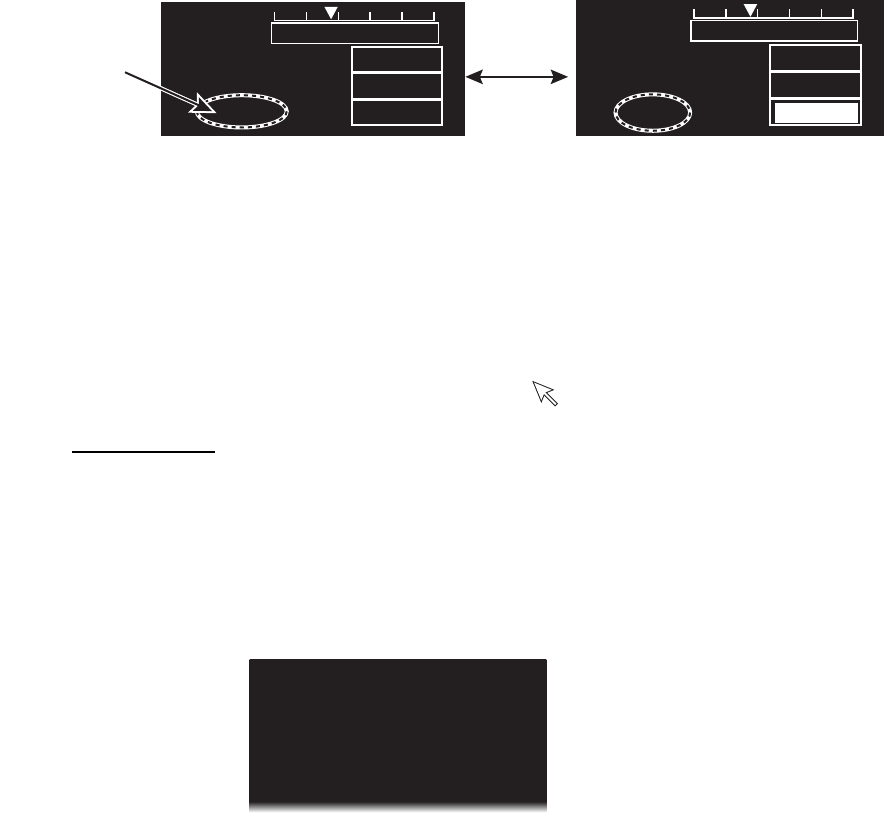
1.14 How to Reduce the Sea Clutter
The reflected echoes from the waves
appear around your ship and are
called “sea clutter”. The sea clutter
extends according to the height of
waves and antenna above the water.
When the sea clutter hides the
targets, reduce the clutter, either
manually or automatically.
1. Click the STC mode icon at the bottom right corner on the screen to show [MAN]
or [AUTO] as appropriate.
2. For manual adjustment, rotate the setting knob to adjust the sea clutter so that the
clutter is broken into small dots, and small targets become identified. If the setting
is too low, targets are hidden in the clutter. If the setting is too high, both sea clutter
and targets disappear from the display. Normally adjust the control until the clutter
has disappeared to leeward, but a small amount of the clutter is visible windward.
For auto mode, the setting range is -50 to 50. For manual mode, 0 to 100.
STC PRESET
You can tune STC properly with the [STC PRESET] function.
1. Click the STC mode icon to set [MAN] (Manual mode).
2. Put the cursor on the STC setting box at the bottom right corner on the screen.
3. Rotate the setting knob to set the level to use as lowest level for STC adjustment.
4. Open [MAIN MENU], click [ECHO].
5. Click [STC PRESET].
6. Click [ON] to activate the
[STC PRESET] function. The STC
bar is re-scaled to set the STC level
to zero.
Sea clutter at screen
center
STC adjusted; sea
clutter suppressed
[AUTO]: Auto [MAN]: Manual
MAN TUNE
AUTO GAIN
AUTO STC
AUTO RAIN
0
0
0
MAN TUNE
AUTO GAIN
MAN STC
AUTO RAIN
0
100
0
Click
STC mode
icon
MAN TUNE
AUTO GAIN
MAN STC
AUTO RAIN
0
100
0
STC setting box
0 100
Current level
0 100
STC PRESET [ON]
STC PRESET [ON]
Change of the STC scale bar
1. OPERATION
1-20
1.15 How to Reduce the Rain Clutter
The reflections from the rain or snow appear on the screen. These reflected echoes
are called “rain clutter”. When the rain clutter is strong, targets in the rain clutter are
hidden in the clutter. Reflections from the rain clutter are easily identified from true
targets by their wool-like appearance.
The rain control breaks the continuous display of rain or snow reflections into a
random pattern. When the rain clutter hides the targets, adjust the rain control
(automatic or manual) to reduce the clutter.
1. Click the rain mode icon at the bottom right corner on the screen to show [MAN]
or [AUTO] as appropriate.
2. For manual adjustment, rotate the setting knob to reduce the rain clutter.
For auto mode, the setting range is -50 to 50. For manual mode, 0 to 100.
1.16 Cursor
Within the radar display, the cursor is shown by a plus sign (+). When the cursor is
outside the radar display it comes to an arrow ( ).
Cursor menu
Functions that require the use of the cursor, such as EBL offset, may be activated
directly from [CURSOR MENU]. This menu is available when the cursor is inside the
effective display area.
1. Put the cursor anywhere within the radar display.
2. Press the right button to show [CURSOR MENU].
3. Use the touch pad to select the desired menu.
[ACQUIRE]*: Acquires a target (TT or AIS).
[REF MARK]*: Acquire a target to use to gauge own ship’s speed.
[OFFCENTER]: Off-center your position.
[EBL OFFSET]: Shift the origin of an EBL.
*: This function is available for [SEA] mode only.
[AUTO]: Auto [MAN]: Manual
MAN TUNE
AUTO GAIN
AUTO STC
MAN RAIN
MAN TUNE
AUTO GAIN
AUTO STC
AUTO RAIN
0
0
0
0
0
100
Click
Rain mode
icon
[CURSOR MENU]
1 BACK
2 ACQUIRE
3 REF MARK
4 OFFCENTER
5 EBL OFFSET