Futaba L35-N4581 Radio Control Transmitter User Manual
Futaba Corporation Radio Control Transmitter
Futaba >
Contents
- 1. user manual I
- 2. user manual II
- 3. user manual III
user manual I

L35-28199-00
Please read this manual before using the product.
OPERATION MANUAL
Unmanned Helicopter for
Industrial Applications
Foreword
Thank you for purchasing the FAZER, an unmanned helicopter for industrial applications.
This operation manual describes the proper method for operating the FAZER and precau-
tions.
Be sure to read this manual and thoroughly understand its contents before operating the
FAZER.
In this manual, the warning messages that are necessary to ensure the safe and proper
operation of the FAZER are classified as shown below. Make sure to observe these instruc-
tions because they all contain important information.
●After you have read this operation manual, keep it within easy access near the helicopter.
●Contact your dealer if you are lending this helicopter or transferring its ownership.
●Keep this operation manual together with the helicopter if you are lending this helicopter
or transferring its ownership.
●If you have lost this operation manual, contact your dealer to request another copy.
●Contact your dealer if you have any questions or comments regarding the contents of
this operation manual.
●Due to specification changes, some of the textual or graphical contents of this manual
may differ from the actual helicopter.
●For information regarding the sprayer, refer to the operation manual for the sprayer.
Improper operation will cause imminent dan-
ger, which could lead to serious injury or
death.
Improper operation could lead to injury, seri-
ous injury or death.
Improper operation could cause property
damage.
Describes the proper handling method or
gives the main points for inspection and
maintenance.
Indicates a prohibited action.
An adjacent illustration describes the
prohibited action.
DDANGER
WWARNING
NNOTICE
TIP

Table of Contents
Safety Precautions 1
Product Specifications 2
Part Names and Functions 3
Pre-Flight Preparation 4
Flying Procedure 5
Post-Flight Cleaning and Servicing 6
Simple Maintenance 7
Proper Management 8
Product Management 9
Troubleshooting 10
Index 11

Safety Precautions
Product Safety Label Locations ................................................... 1-1
Make Sure to Follow the Instructions........................................... 1-2
Basic requirements .................................................................................................. 1-2
Operator requirements............................................................................................. 1-3
Helicopter requirements........................................................................................... 1-5
Flight requirements .................................................................................................. 1-7
Chemical requirements .......................................................................................... 1-11
1
1-1
Safety Precautions
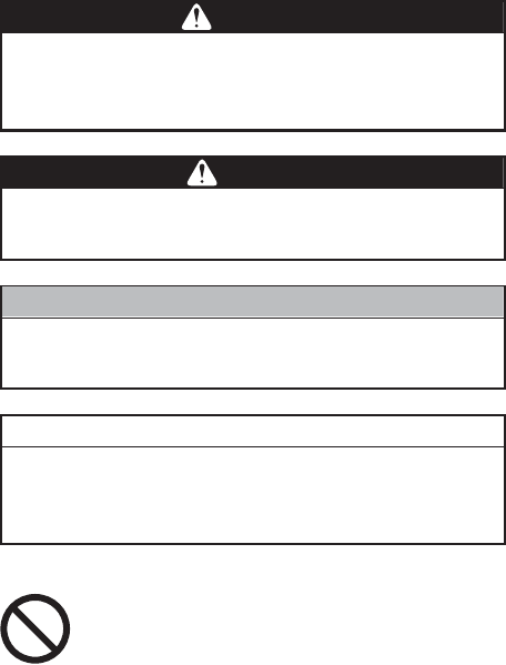
Read and thoroughly understand the product safety labels affixed to the helicopter before operation.
Product Safety Label Locations
Placed on the left and right.
Safety Precautions
1-2
Basic requirements
Make Sure to Follow the Instructions
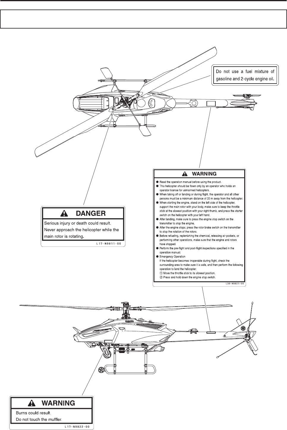
To ensure safe operation, make sure to thor-
oughly read the operation manual before
operation.
WWARNING
This unmanned helicopter for industrial
applications has been manufactured for the
purpose of the aerial application of agricul-
tural chemicals, fertilizers, and seeds. Do not
use it for other applications, which is in viola-
tion of laws, and could lead to accidents.
WWARNING
Do not modify the helicopter or the auxiliary
devices. Do not use parts other than genuine
parts. Any modification of the helicopter or
use of non-genuine parts may cause unex-
pected accidents.
WWARNING
Safety Precautions
1-3
Operator requirements
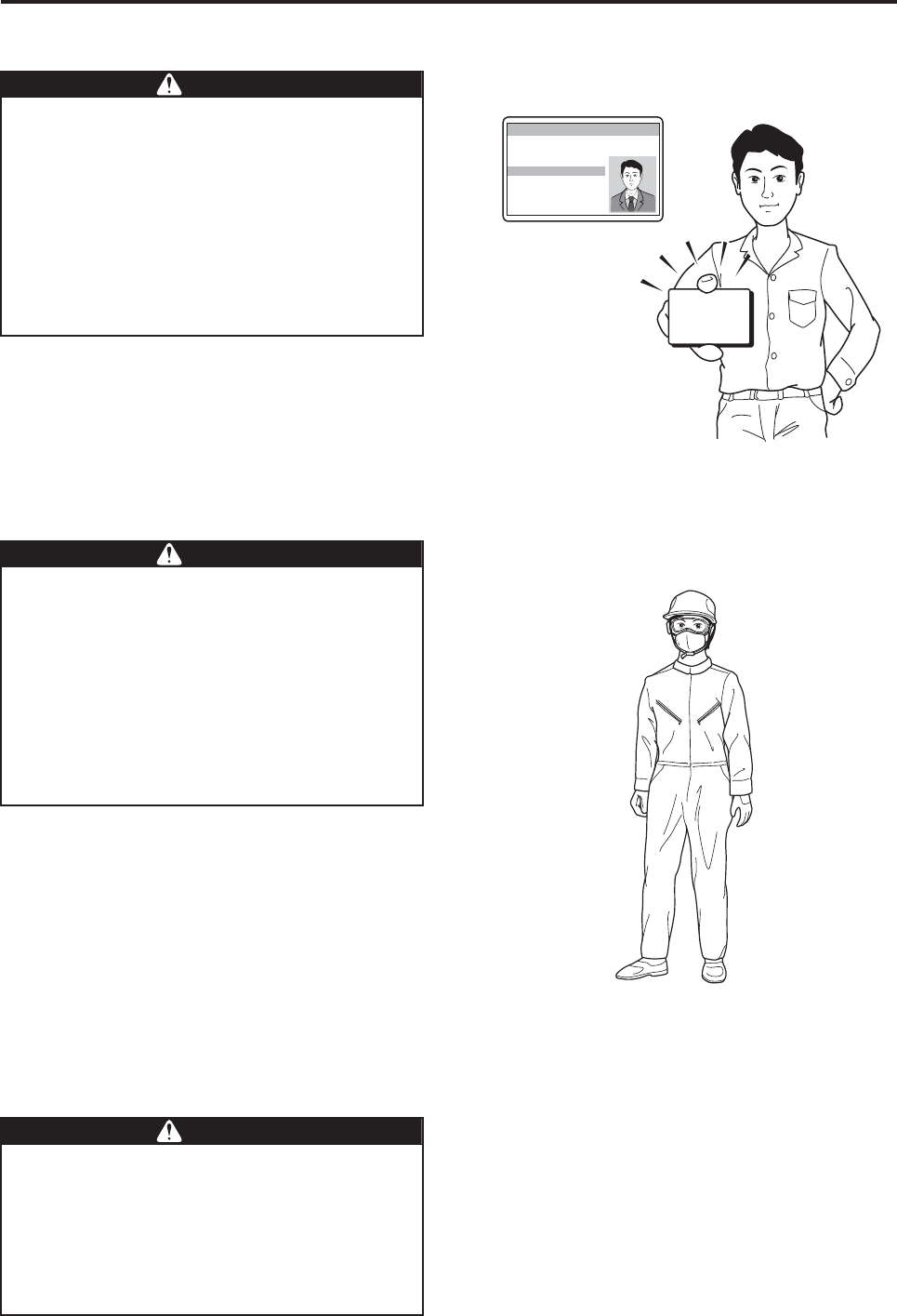
Observe the following clothing requirements:
•Wear a helmet.
•Wear goggles and a particle mask.
•Wear long-sleeved clothing with secure buttons
and fasteners.
•Wear slip-proof shoes that are easy to walk with.
• Do not wear objects that could obstruct vision
when there is wind, or adversely affect operation
(especially towels and gloves).
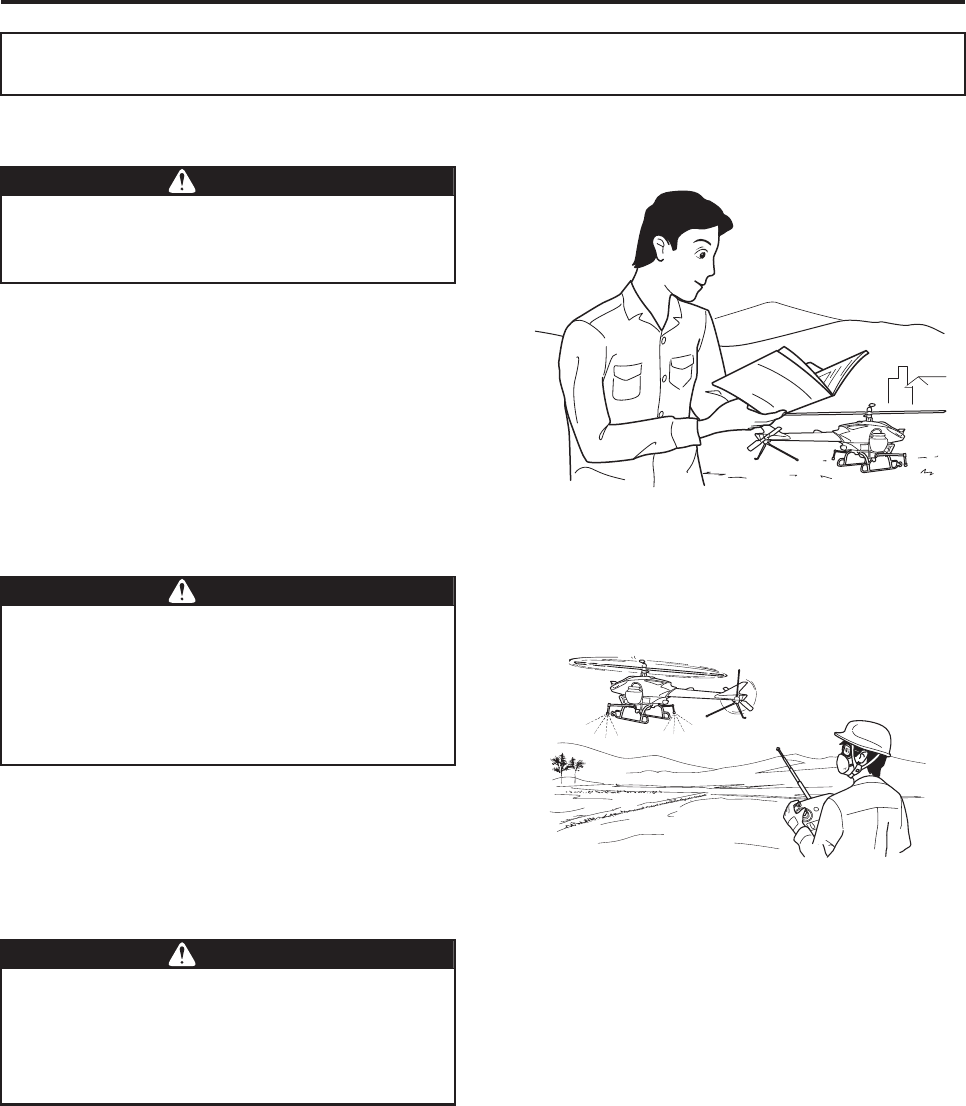
Flying this helicopter requires a high level of
skill.
Therefore, it should be flown only by an oper-
ator who holds an operator license for
unmanned helicopters, issued by Yamaha
Motor Co., Ltd.
In addition, if the country where the
unmanned helicopter will be used requires
an operator license, obtain the license before
flying the helicopter.
WWARNING
License
Operator License for Unmanned Helicopters for Industrial Applications
Name:
Make sure to wear a helmet during flight. To
perform an aerial application, make sure to
wear clothing that is appropriate for the oper-
ation. Performing a flight and an aerial appli-
cation in clothing that is not appropriate for
the task could cause loss of visibility, maneu-
vering error, or cause your foot to slip, result-
ing in unexpected accidents. Furthermore, it
could harm your health through exposure to
agricultural chemicals.
WWARNING
A minimum of three people is required for an
aerial application: a signaler who has been
briefed on the aerial application procedure,
an assistant who readies, mixes, and sup-
plies agricultural chemicals, and an operator.
Beware that an understaffed operation could
lead to an accident.
WWARNING

Safety Precautions
1-4
The operation of an unmanned helicopter
involves considerable mental fatigue. The
operator should not fly the helicopter contin-
uously for more than one hour, but should
take a rest every hour. Prolonged continuous
flight operation could cause the operator to
lose concentration and could lead to an acci-
dent.
Do not fly the helicopter after drinking alco-
hol or taking a cold medicine, or if you are in
poor physical condition. Flying the helicopter
in poor physical condition could cause loss
of concentration, and could lead to an acci-
dent.
WWARNING
WWARNING
Safety Precautions
1-5
Helicopter requirements
Make sure to perform the following inspections. Have
the 30-hour free inspection and periodic inspections
performed at your dealer.
• Pre-flight inspection
• Post-flight inspection
• 30-hour free inspection
• Periodic inspection
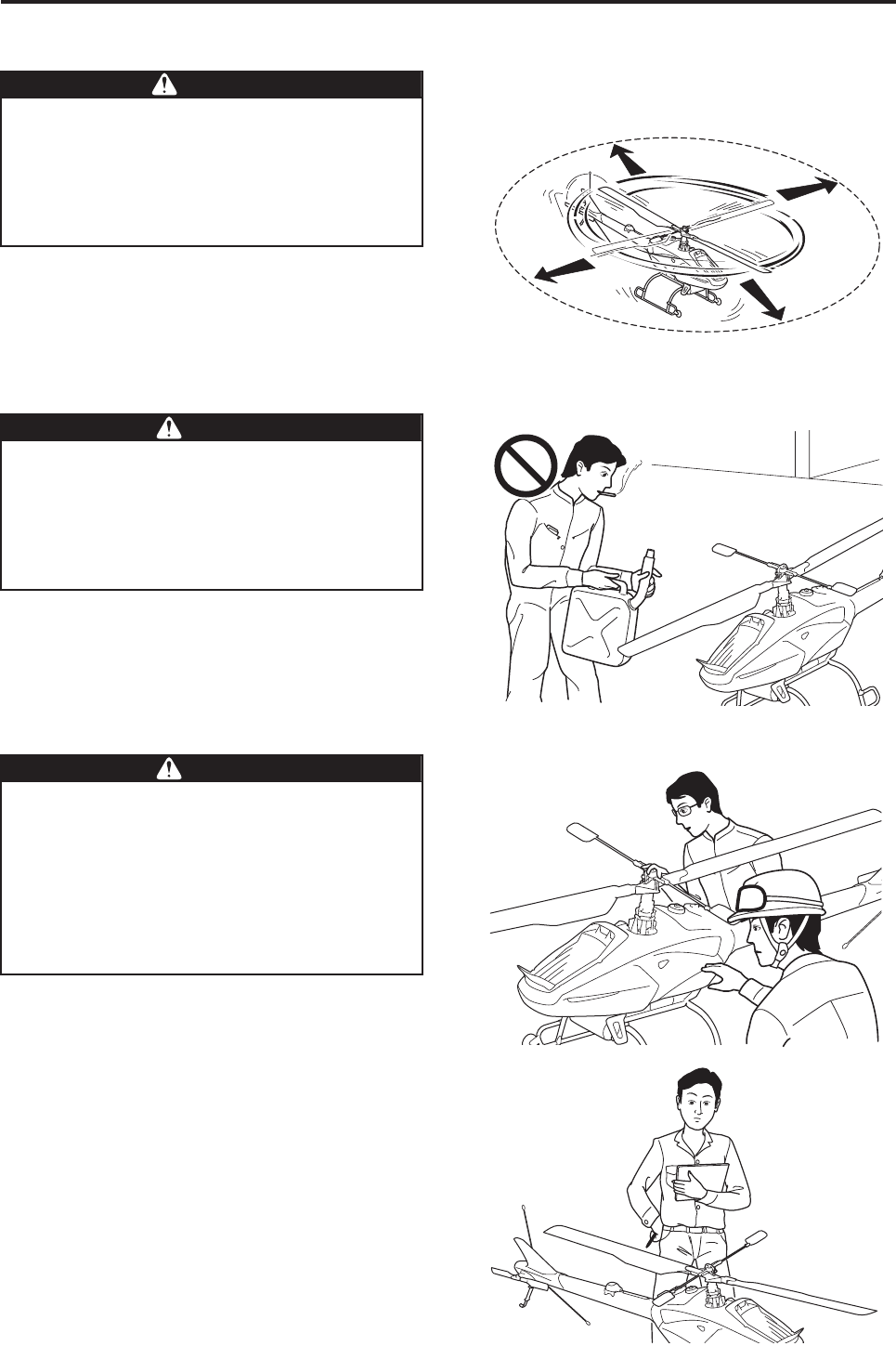
Never enter (or allow others to enter) the area
within 20 meters of the helicopter until the
main rotor has come to a complete stop and
the engine has stopped. Failure to observe
this precaution could cause a serious acci-
dent.
DDANGER
20 m
20 m
20 m
20 m
Gasoline is a highly volatile substance that
ignites easily. Before refueling, be sure to
stop the engine, and do not place a source of
fire or sparks nearby. Failure to observe
these precautions can cause the gasoline to
ignite.
WWARNING
●Make sure to have the required inspec-
tions and maintenance services per-
formed. Failure to do so could lead to a
serious accident.
●To have the helicopter serviced, contact
your dealer or an authorized service facil-
ity for Yamaha unmanned helicopters for
industrial applications.
WWARNING
OK!
OK!
Safety Precautions
1-6
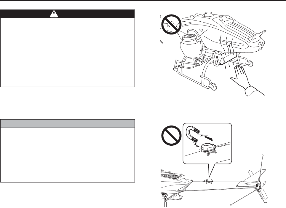
The muffler reaches a high temperature
immediately after a flight. To prevent burns,
do not touch it. To prevent burns or fire, do
not place any flammable objects near the
muffler. Also, touching it with oily shop rags
or bare hands can leave their traces after
combustion.
For cleaning, use shop rags that do not con-
tain oil or grease.
WWARNING
The gyro sensor (integrated GPS/gyro sen-
sor) attached to the top of the tail body is a
precision instrument that senses the Earth’s
feeble magnetic force. Do not place any mag-
netized objects near it, which could cause
the sensor to malfunction and the controls to
function improperly.
NNOTICE
Safety Precautions
1-7
Flight requirements
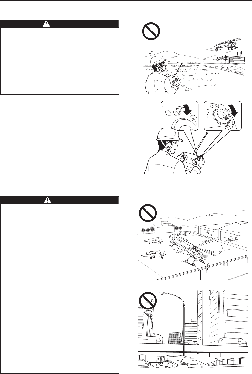
If the unmanned helicopter goes out of con-
trol beyond its flying range, make sure the
area is uninhabited and safe, before perform-
ing the operation described below in order to
drop the helicopter.
1Place the throttle stick to its SLOWEST
position.
2Press and hold the engine stop switch
down.
DDANGER
21
Never fly the helicopter in no-fly zones.
Flying in a no-fly zone can lead to a serious
accident or exposure to chemicals.
Do not fly in the following areas.
●In the vicinity of or above airports, military
facilities, heliports for manned helicopters,
and gliding fields.
The peripheral distances from no-fly zones
vary by facility; contact the relevant
authorities for details.
●In the vicinity of or above heavily trafficked
roads, expressways, or railroads.
WWARNING
Safety Precautions
1-8
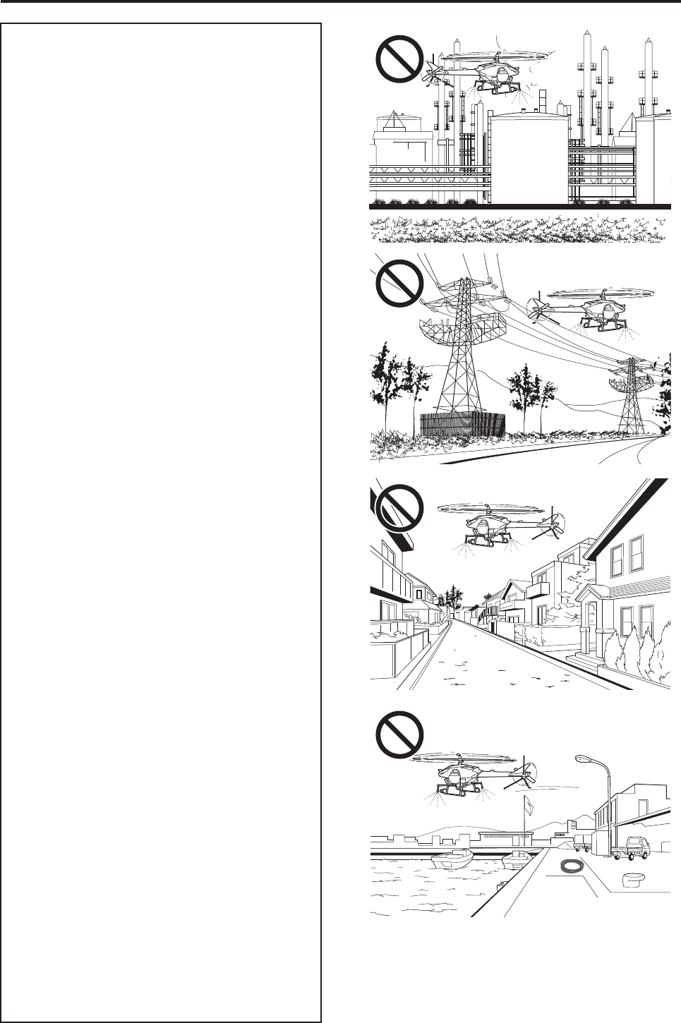
●In the vicinity of or above petroleum, gas,
chemical, and explosive complexes, tanks,
or storage areas.
●In the vicinity of or above high-voltage
transmission lines, power generating
plants, or power substations.
●In the vicinity of or above homes adjacent
to the aerial spray area, or other hazardous
obstacles.
●In the vicinity of or above port and harbor
facilities including swimming areas, yacht
harbors, fishing ports, reservoirs for pota-
ble water, or dams.
●In the vicinity of or above areas posted
with “no trespassing” or “keep out” signs.
●In the vicinity of or above areas where
flight is prohibited by police or fire depart-
ments.
Safety Precautions
1-9
The unmanned helicopter for industrial appli-
cations is operated by way of radio signals.
To prevent the helicopter from going out of
control due to unexpected radio signal inter-
ference, pay careful attention to the radio sig-
nals before and during a flight.
WWARNING
Select areas that are appropriate for takeoffs
and landings, as described below. Failure to
select an appropriate area could lead to an
accident.
●Select flat farm roads or vacant lots with
minimal foot or vehicle traffic.
●Check that there are no obstacles in the
vicinity.
●Check that there are no objects that could
fly up with the wind (such as mowed
grass, plastic tape, plastic bags, etc.).
WWARNING
Cancel a flight or aerial application plan if
poor weather conditions exist as described
below. Failure to do so could pose operation
difficulties, which could lead to an accident,
and could adversely affect the application and
the effectiveness of the sprayed chemicals.
●Wind velocity in excess of 3 m/s at a
height of 1.5 meters above the ground.
●Rain, fog, or lightning in the vicinity.
WWARNING
Rain, Fog, or Lightning
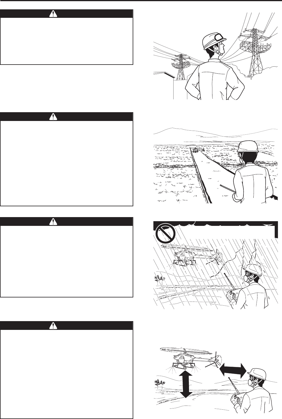
Keep the maximum horizontal distance
between the operator and the helicopter
within 150 meters. Keep the height of the
helicopter between 3 and 4 meters from the
ground or the crop. If the distance is any
greater, it will prevent the operator from mon-
itoring the posture of the helicopter and
adversely affect signal reception.
For safety, further shorten the distance if
there are any obstacles in the area.
Failure to fly the helicopter within the maxi-
mum distance limit could lead to an accident.
WWARNING
150 m max
3 to 4 m
Safety Precautions
1-10
Adjust the load to leave some leeway in pay-
load. A takeoff with the maximum payload
requires maximum horsepower and careful
flying technique. An excess payload at this
point could lead to a serious accident. There-
fore, hover the helicopter to check that there
is an ample margin in payload before con-
tinuing with the flight.
WWARNING
If, during a flight, the warning lamp indicates
an abnormal condition or the helicopter
exhibits an abnormal behavior or symptom
(vibration, sound, coolant leakage, foul odor,
etc.), immediately land the helicopter in a
safe area. Failure to discontinue the flight
can lead to an accident.
WWARNING
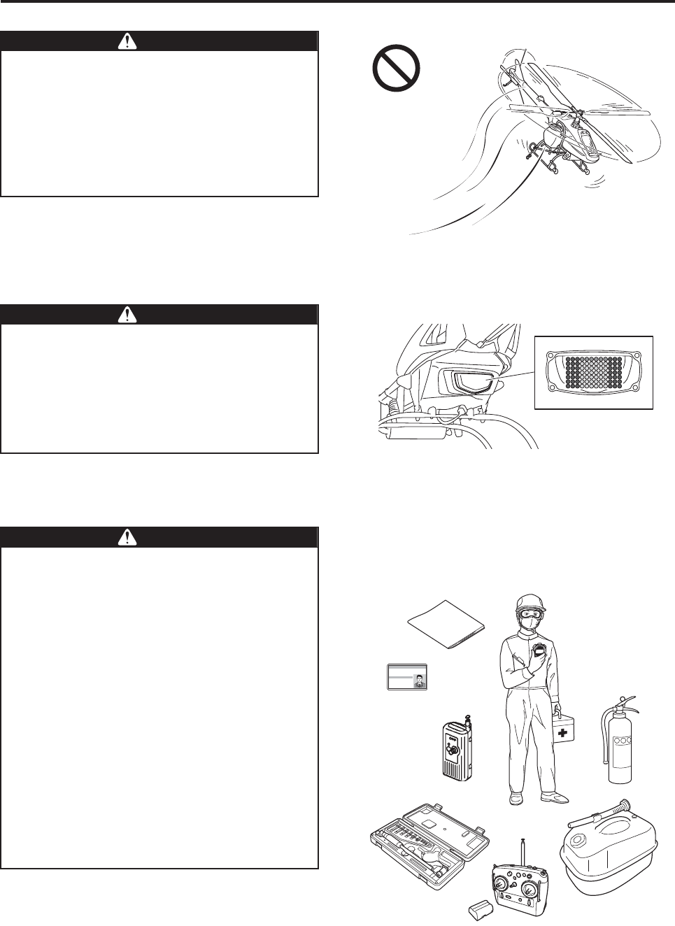
Bring the following items with you to the fly-
ing site.
Failure to do so could adversely affect the
flight and lead to an accident.
●Radio signal monitor (sold separately)
●Fire extinguisher
●First-aid kit
●Stopwatch
●Tools
●Fuel
●Helmet (for all personnel)
●Spare battery
●Transceiver
●Flight log
●Operation Manual
●Proficiency certificate
●Particle mask
●Goggles
WWARNING
Safety Precautions
1-11
Chemical requirements
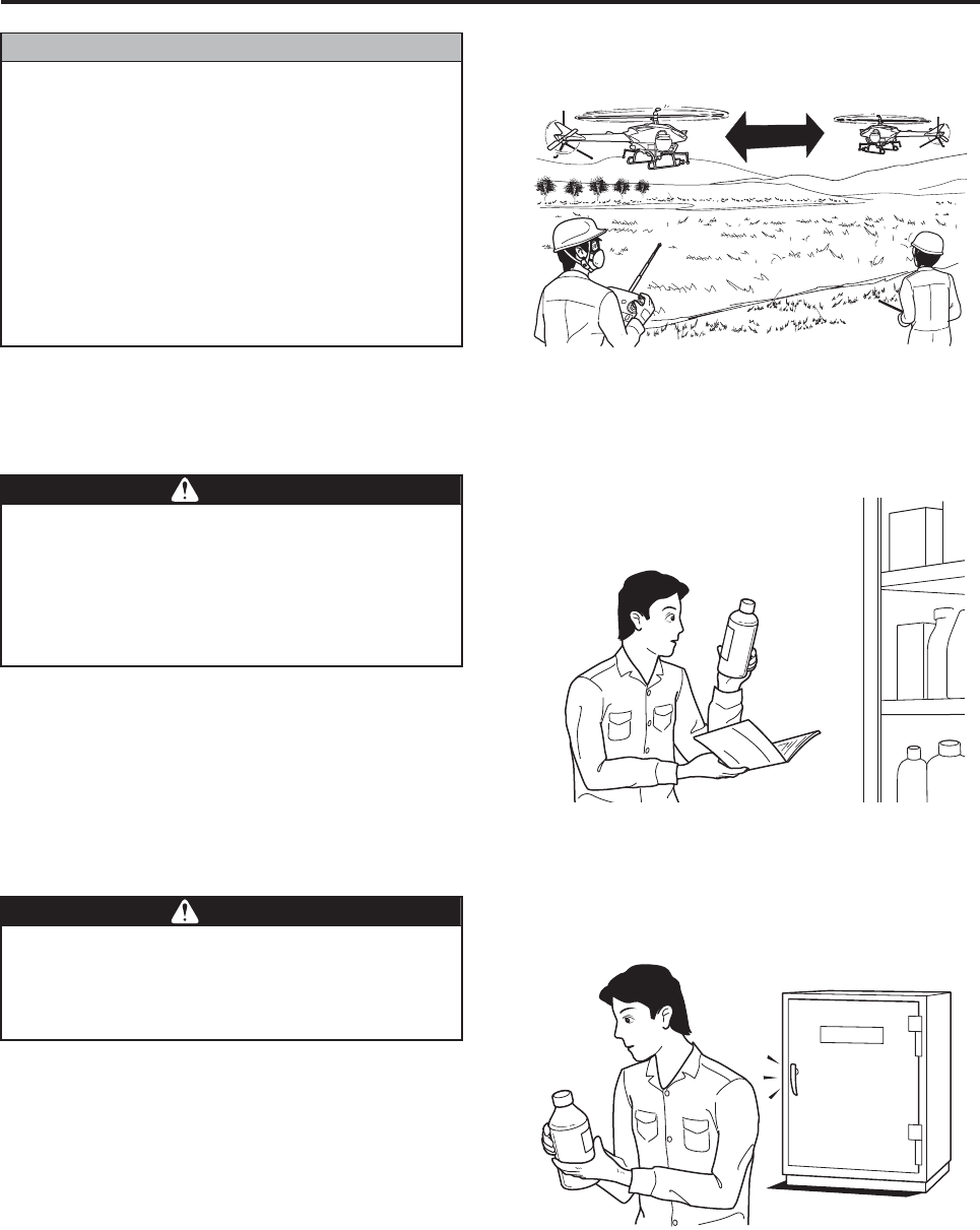
To fly two or more helicopters simulta-
neously in the same area,
1Do not use the same frequency.
2The maximum distance between the oper-
ator and the helicopter should be 150
meters.
3Keep a minimum distance of 200 meters
between helicopters.
Be sure to adhere to the requirements above.
NNOTICE
200 m minimum
Do not use chemicals other than those that
have been registered for use with unmanned
helicopters. Failure to do so could expose
animals, plants, or people to chemicals for
which the operator will be required to take
social responsibility.
WWARNING
Control and handle chemicals strictly in
accordance with their manuals. Failure to
control or improper handling could lead to
chemical pollution or health hazards.
WWARNING

Product Specifications
Specification Data........................................................................ 2-1
Data list .................................................................................................................... 2-1
Dimensions .............................................................................................................. 2-2
2

2-1
Product Specifications
Data list
*1 Transmitter for sprayer is sold separately.
Specification Data
Product name FAZER
Manufacturer model L35
Perfor-
mance
Chemical payload 24 kg
Practical distance (visual range) 150 m
Engine
Type 4-stroke per cycle, horizontally opposed 2-cylinder
Cylinder displacement 390 cc
Maximum output 19.1 kw (26 ps) minimum/6,000 rpm
Maximum torque 32.5 N·m (3.3 kg·m)/4,500 rpm
Cooling
System Water-cooled
Specified
coolant Mixture of Yamaha Long-Life Coolant and water
Mixing
ratio 1 part Yamaha Long-Life Coolant to 1 part water
Lubrication
System Force-feed wet sump
Specified
oil Yamalube Standard Plus: SAE 10W-40
Starting system Electric starter
Fuel
Type Regular gasoline
Tank
capacity 5.0 liters
Electrical
Control system
Name YACSII
Warning
system Warning lamp/self monitor
Warnings Low fuel level, excess load, radio signal interference,
speed warning, etc.
Radio signals for piloting 72.690 /.710 /.730 /.770 /.790 /.810 /.850 /.890 /.910 /.950 MHz
Radio signals for sprayer *1 26.995 /27.045 /27.095 /27.145 /27.195 /27.255 MHz
Battery Helicopter VRLA (valve-regulated lead acid) battery YTZ7S(F) 12 V, 6 Ah
Transmitter Lithium-ion battery 7.4 V, 2,450 mAh
Ignition plug NGK CPR7EA
Helicopter
dimensions
Main rotor diameter 3,115 mm
Tail rotor diameter 550 mm
Overall length/overall length with
rotors 2,782 mm/3,665 mm
Overall width 770 mm
Overall height 1,078 mm
Product Specifications
2-2
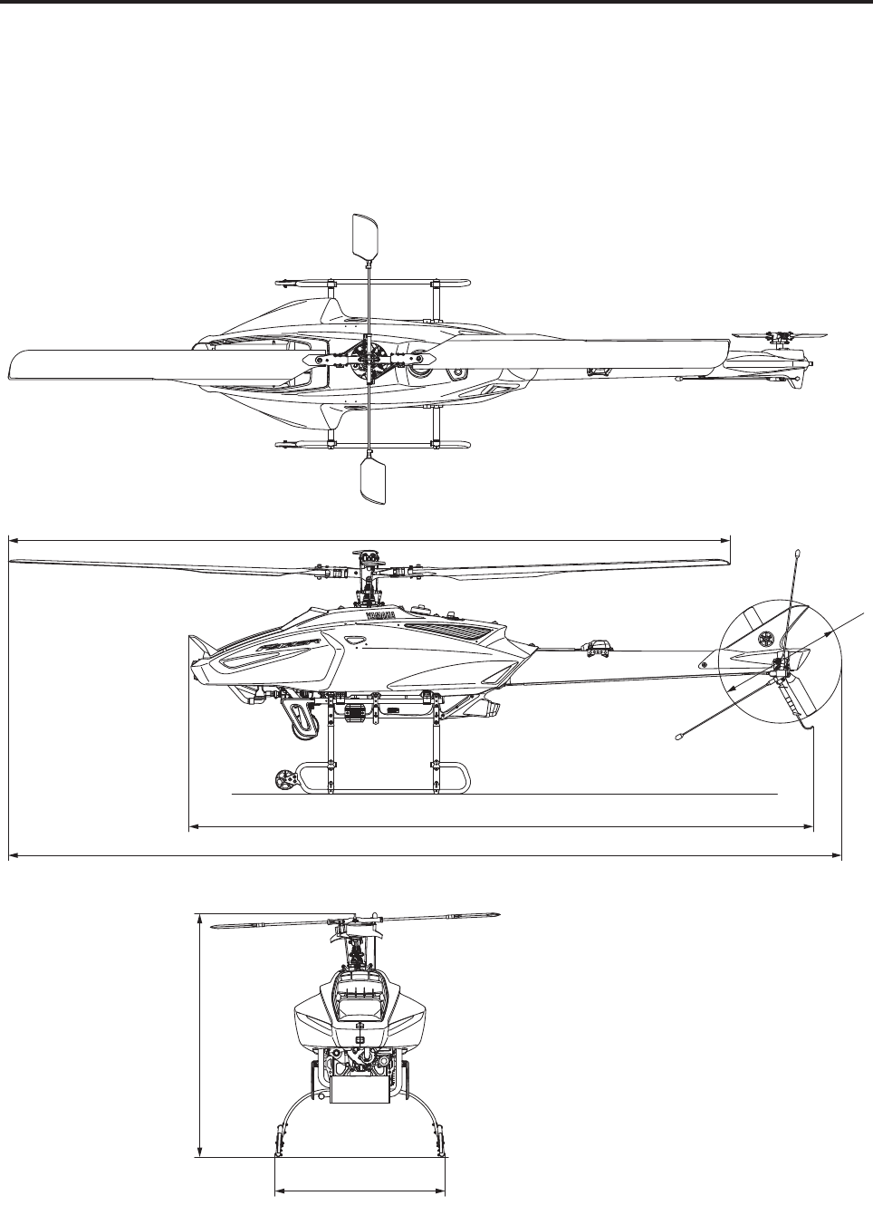
Dimensions
Unit: mm
770
1,078
3,665
2,782
3,115
550

Product Specifications
2-3

Part Names and Functions
Helicopter Exterior ....................................................................... 3-1
Helicopter exterior parts names ............................................................................... 3-1
Control panel, warning lamp, and self monitor......................................................... 3-2
Helicopter Interior Parts ............................................................... 3-3
Flight Transmitter......................................................................... 3-4
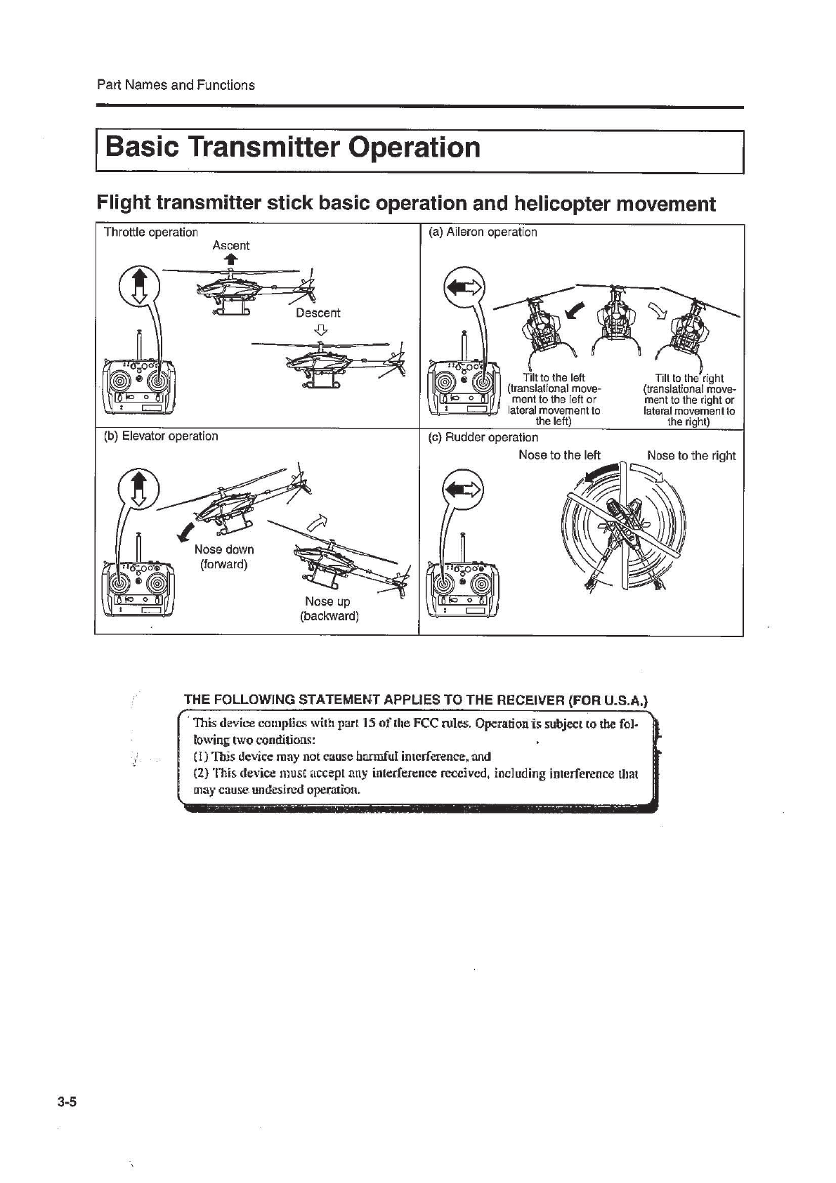
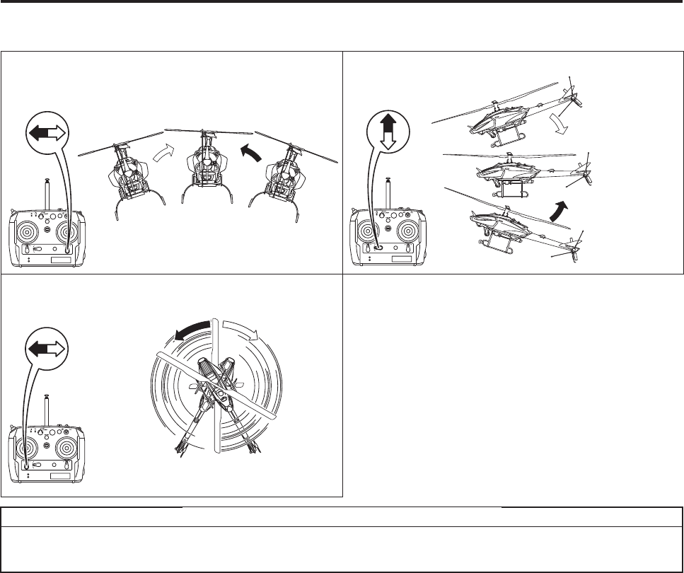
Basic Transmitter Operation ........................................................ 3-5
Flight transmitter stick basic operation and helicopter movement ........................... 3-5
Flight transmitter trim lever basic operation and helicopter movement.................... 3-6
GPS switch .............................................................................................................. 3-7
Spray switch............................................................................................................. 3-8
Frequency settings and checks ............................................................................... 3-8
Transmitter battery monitor lamp ............................................................................. 3-9
Various Types of Warning (Warning, Indication) and Actions ... 3-10
Self monitor............................................................................................................ 3-10
Warning lamp......................................................................................................... 3-11
Safe Functions During Failsafe Mode
(Radio Signal Interference)........................................................ 3-13
Safety Functions and Actions in Case GPS Reception
Becomes Poor While Flying Under Speed Control.................... 3-16
3
3-1
Part Names and Functions
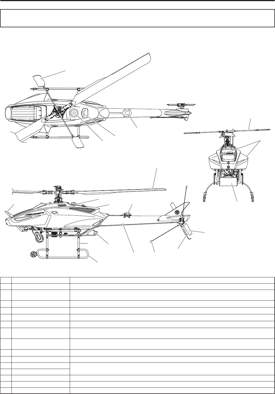
Helicopter exterior parts names
Helicopter Exterior
No. Name Function
1Main rotor Generates main lift and propelling force.
2Stabilizer Stabilizes the helicopter by way of the inertial and aerodynamic forces created by the rotating right and left
weights (stabilizer blades).
3Fuel tank cap A fuel tank cap with air release function.
4Control panel A panel for starting and controlling the engine.
5GPS/gyro sensor Receives GPS radio signals. / Detects the Earth’s magnetic field.
6Antenna (
72 MHz band
) Receives radio signals from the transmitter.
7Tail rotor Prevents the helicopter from rotating in reaction to the rotation of the main rotor, thus effecting control in the head-
ing direction.
8Stone guard A handle to be grasped when transporting the helicopter on land. Also, a portion that is held by hand or stepped
by foot while attaching a transport wheel onto the runner.
9Tail body Connects the helicopter body with the tail rotor, and houses a driveshaft and the like.
0Warning lamp Indicates the conditions of the helicopter by way of how the lamp illuminates.
ARunner Supports the helicopter.
BLeaf
CMuffler Muffles and minimizes the exhaust sound of the engine.
DSide cover Protects the main components, including the engine.
ERadiator cover Directs the cooling air to the radiator.
2
3
4D
C
7
?
8
9
5
6
B0
E
A
3
4
5
2
1
Part Names and Functions
3-2
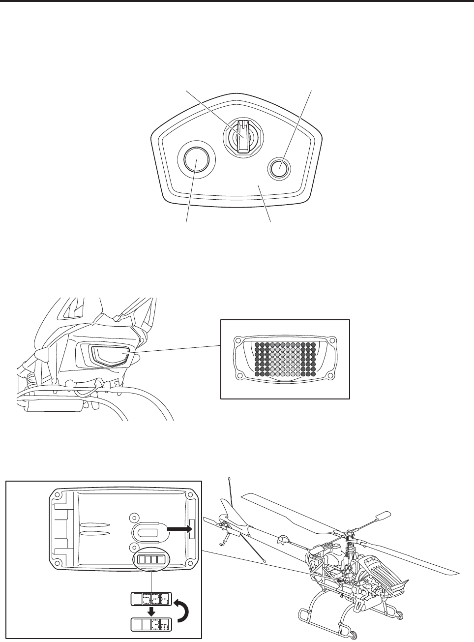
Control panel, warning lamp, and self monitor
STARTER
OFF
ON
Main Switch Flight lamp
Warning lamp
Control panel
Self monitor
Control panel
Starter switch
Indication examples
Example: flight hours:
52 hours 3 minutes
FWD
(front)
Part Names and Functions
3-3
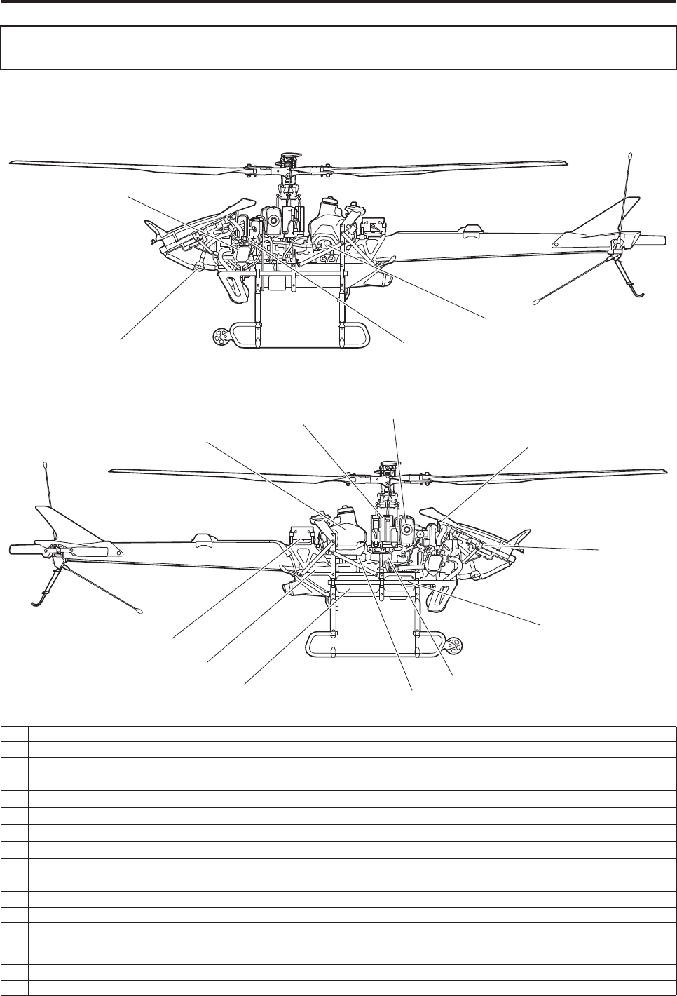
Helicopter Interior Parts
2
1
9 (interior)
B
4
3
6
8
A
D
7
0
E
5
C
No. Name Function
1Engine The motive force that moves the helicopter.
2Thermostat A device to automatically regulate the water temperature.
3Injector A device to inject fuel into the engine.
4Fuel pump A device to pump fuel from the fuel tank.
5Control unit Detects the postural changes of the helicopter.
6Fuel tank A tank to store fuel.
7Slide servo A servo to control the angle of the main rotor.
8Throttle servo A servo to control the engine power output.
9Rudder servo A servo to control the angle of the tail rotor.
0Radiator cap A cap at the inlet for pouring coolant into the radiator.
ARadiator A device to dissipate heat from the engine coolant.
BAir cleaner A device to remove dust from the air intake of the engine.
CTransmission Consisting of speed gears and drive shaft, this is a speed-reduction device that transmits the motive force from
the engine to the main rotor shaft and the drive shaft.
DTail drive shaft A shaft to transmit the motive force from the transmission to the tail transmission.
EFrame A framework that supports the helicopter.
Part Names and Functions
3-4
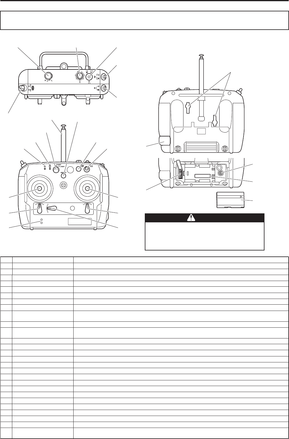
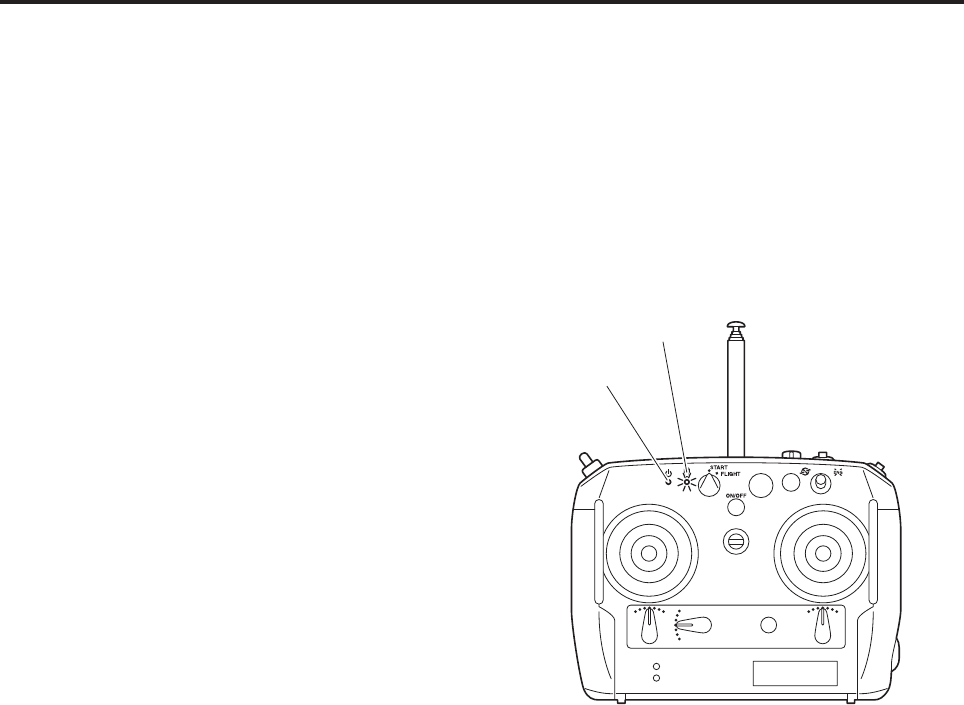
Flight Transmitter
No. Name Function
1 Power switch This switch is for turning the transmitter power ON and OFF.
2 Battery monitor lamp Indicates the state-of-charge of the transmitter battery by its color.
3 Output lamp Indicates the output conditions of the radio signals.
4 Flight switch A switch to select START and FLIGHT.
5 Rotor brake switch A switch to quickly stop the main rotor after the engine has been stopped.
6 Engine stop switch A switch to stop the engine.
7 Spray volume switch A switch to select the spraying width of the liquid or granular sprayer.
8 Spray switch A switch to turn the sprayer ON and OFF.
9 Speed-linked spray switch A switch to turn ON/OFF the function to adjust the spray volume that suits the flight speed while receiving GPS
signals.
10 Liquid volume knob A knob to adjust the speeds of the liquid sprayer pump motor or the granular spinner motor.
11 Rotor speed adjustment
knob A knob to change the speed of the main rotor.
12 GPS switch While receiving 4 or more GPS signals, this switch enables the helicopter to fly at a constant speed.
13 Antenna Transmits radio signals.
14 Throttle stick A stick to control the ascent and descent of the helicopter.
15 Aileron stick A stick to control the right and left tilt of the helicopter.
16 Elevator stick A stick to control the front-back tilt of the helicopter.
17 Rudder stick A stick to control the horizontal rotation of the helicopter.
18 Aileron trim lever A lever that minutely controls the right and left tilt of the helicopter.
19 Elevator trim lever A lever that minutely controls the front-back tilt of the helicopter.
20 Rudder trim lever A lever that minutely controls the horizontal rotational movement of the helicopter.
21 Warning speaker Emits a sound to warn you of the battery state-of-charge or the like.
22 Battery It is a lithium-ion battery.
23 Serial No. A unique number for the transmitter.
24 Function selector switch Not used.
25 Setup plug hole Not used.
26 Frequency selector switch A switch to change the operating frequency.
27 Blind plug for adjusting stick
operability Not used.
This has been properly adjusted at the factory.
It should not be tampered by the user.
Failure to heed this precaution can lead to acci-
dents.
WWARNING
1
4
2
3
5
6
16,17 14,15
18
19
20
21
9
8
7
10
11
12
25
27
23
24
22
13
26
Part Names and Functions
3-6
Flight transmitter trim lever basic operation and helicopter movement
(a) Aileron trim lever (b) Elevator trim lever
(c) Rudder trim lever
Stops drifting
to the left.
Stops drifting
to the right.
Stops drifting
forward.
Stops drifting
backward.
Stops the nose
from turning to
the left.
Stops the nose
from turning to
the right.
●The neutral position is the standard position for the aileron, elevator, and rudder trim levers.
●Make fine adjustments in accordance with the conditions.
TIP
Part Names and Functions
3-7
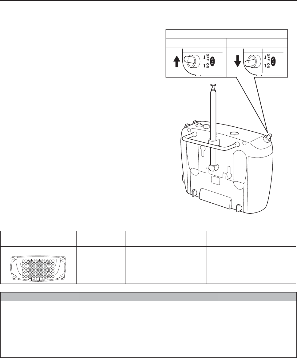
GPS switch
Turning the GPS switch ON enables helicopter
speed control through the use of the GPS function
(to maintain a constant flight speed).
The GPS switch can be used while it is turned ON
before takeoff. The flashing of the yellow warning
lamp indicates that the reception of the GPS sig-
nals is poor, and the speed control function is unus-
able.
In the situation indicated below, momentarily turn
the switch OFF; then, turn it back ON. Otherwise,
you will not be able to use the speed control flight
mode.
GPS Switch
Speed control OFF Speed control ON
Indications Indication
conditions Indication meanings Actions
Yellow lamp Regular flashing Unable to effect speed control
Poor GPS signal reception
Able to fly under postural control
●If a failure occurs in postural control, it switches to manual operation and disengages the speed
control.
●Even if GPS signals are being received, the accuracy of the radio signals from the satellites may
be poor.
In that case, the helicopter might move front-back, side-to-side, or up and down. When this hap-
pens, quickly turn the GPS switch OFF.
To use the speed control again, wait a while before turning the GPS switch ON.
NNOTICE
Part Names and Functions
3-8
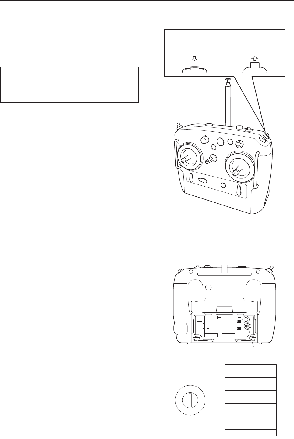
Spray switch
When the flight transmitter is powered ON and the
helicopter main switch is in the ON position, the
sprayer can be operated.
When the flight transmitter’s spray switch (ON/OFF
switch) is pressed ON, the sprayer operates. Press-
ing it again (to release), the sprayer stops.
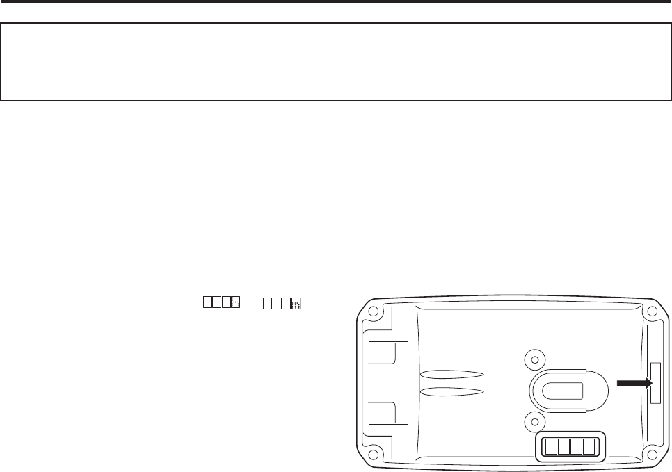
Frequency settings and checks
How to select frequencies
Select the frequency for the helicopter by turning
the frequency selector switch as shown.
Before making a selection, be sure the transmitter’s
power switch is OFF.
Radio signals are assigned to numbers 0 to 6.
Do not turn the switch to number 7 and beyond.
Frequency checks
Use a radio signal monitor (sold separately) to
make sure there are no radio signals being used in
the vicinity. Then, turn ON the transmitter’s power
switch.
Use a radio signal monitor (sold separately) to
check that the selected radio signals are being out-
put.
When you press the spray switch ON, be
mindful of the surroundings because the
sprayer will spray agricultural chemicals.
TIP
Push Release
Spray Switch
ON (to operate) OFF (to stop)
0
1
2
3
4
5
6
7
8
9
Number
Frequency
0 72.69 MHz
1 72.71 MHz
2 72.73 MHz
3 72.77 MHz
4 72.79 MHz
5 72.81 MHz
72.89 MHz
72.91 MHz
72.95 MHz
6 72.85 MHz
7
8
9
Frequency selector switch
Part Names and Functions
3-9
Transmitter battery monitor lamp
1Battery state-of-charge inspection
With the helicopter’s main switch turned OFF,
turn the transmitter’s power ON, and inspect the
following items.
●Check that the output lamp and the battery
monitor lamp are illuminated green.
●Check the number of times the buzzer sounds
to indicate the battery state-of-charge.
Check whether the battery monitor lamp is lit.
The battery monitor lamp works in unison with
the buzzer sound that indicates the battery state-
of-charge.
When the battery gets low, the battery monitor
lamp will start flashing red. When the battery
gets even lower, the lamp will stay lit.
At this point, working in unison with the transmit-
ter’s monitor lamp, the warning lamp flashes red
to warn the operator. When this happens, it
means that the battery is practically drained.
Therefore, replace it with a fully charged battery.
* On the FAZER, the red lamp of the helicopter warning lamp flashes to inform the operator that the transmit-
ter’s battery state-of-charge is low during flight. (Refer to page 3-12.)
Beep beep beep beep (4 times) The battery is fully
charged.
Beep beep beep (3 times) The battery needs
to be charged.
Beep beep (2 times) The helicopter can-
not be used unless
the battery is
charged.
Output lamp
Battery monitor lamp
Part Names and Functions
3-10
This product is equipped with various types of
safety functions. Before flight, familiarize yourself
thoroughly with these functions, warnings, and indi-
cations so that you can take appropriate actions.
Self monitor
•Normally when the main switch is turned ON, the
self monitor displays the total flight time to the
present time, in the order from → .
• An error number appears if any type of malfunction is discovered in the helicopter when the main switch is
turned ON or while the helicopter is in flight.
Most of these malfunctions cannot be fixed by the user on the spot. Contact your dealer with the error num-
ber that has appeared, and inquire about the actions that should be taken.
These indications will appear repeatedly until the main switch is turned OFF.
(Indication examples)
E116: Helicopter power failure
Various Types of Warning (Warning, Indication)
and Actions
FWD
(front)
Part Names and Functions
3-11
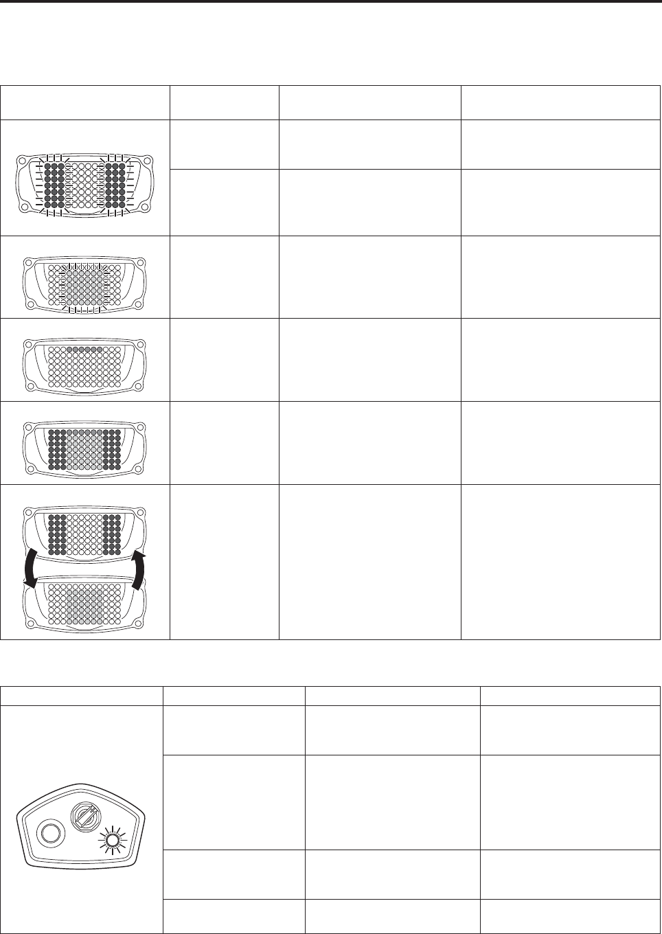
Warning lamp
«Standing by on ground»
Indications Indication
conditions Indication meanings Actions
Red lamp Irregular flashing
Putt-putt···
Putt-putt···
A helicopter failure or mal-
function.
Check the error indicated on the
self monitor and request the
dealer for a repair.
Regular flashing • The remaining fuel is below
the specified amount.
• Transmitter battery low volt-
age warning.
• Refuel.
• Replace the transmitter battery.
Yellow lamp Flashing Unable to effect speed control
Poor GPS signal reception.
Able to fly under postural control.
Blue lamp Illuminating Engine speed limit tripped.
(Transmitter’s flight switch is in
START position.)
Turning the transmitter’s flight
switch to FLIGHT will extinguish
the blue lamp and enable the
helicopter to fly.
Red, yellow, blue lamps All color illumina-
tion
Control instruments being
configured.
Check whether the LED lamp has
an open circuit.
Stand by until the system config-
uration is completed.
Red and yellow Rapid alternat-
ing illumination
The failsafe function has been
tripped due to a failure in
receiving operating radio sig-
nals.
Check the transmitter-receiver.
Flight lamp Indication conditions Indication meanings Actions
Irregular flashing
Putt-putt···
Putt-putt···
The helicopter has some
type of failure and is unable
to fly.
Check the error indicated on
the self monitor and request
your dealer for a repair.
Regular flashing • Control instruments being
configured.
• Pressing the start switch
while security is being
tripped will cause the lamp
to flash.
Stand by until the configura-
tion is completed.
Request the dealer to take
action on the security matter.
Changes from flash-
ing to turning off.
Control instruments configu-
ration completed.
The lamp will change to illumi-
nate when the engine stop
switch is pressed.
Illuminating Engine can be started. Press the starter switch to
operate the starter motor.
STARTER
OFF
ON
Part Names and Functions
3-12
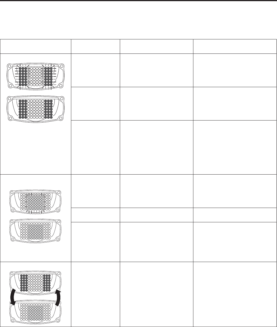
«In flight»
When the warning lamps are OFF, there are no malfunctions.
If a failure occurs during flight, the following indications will appear.
Indications Indication
conditions Indication meanings Actions
Red lamp Irregular flashing
Putt-putt···
Putt-putt···
A helicopter failure occurred,
requiring emergency landing.
A helicopter failure occurred,
preventing it from continuing
a safe flight.
Perform an emergency landing,
check the error indication on the
self monitor, and request the
dealer for a repair.
Regular flashing • The remaining fuel is below
the specified amount.
• Transmitter battery low volt-
age warning.
• Promptly land the helicopter
and refuel.
• Promptly land the helicopter
and replace the transmitter’s
battery.
Illuminating 1Engine speed is low.
2A failure occurred in a
system that does not
affect postural control.
(Example: gyro sensor,
GPS, sprayer failure, etc.)
3The flight speed exceeds
20 km/h.
1Improve flight condition,
reduce payload, etc.
2Check the error indicated on
the self monitor and contact
your dealer.
3Reduce the speed to below 20
km/h.
Yellow lamp Irregular flashing
Putt-putt···
Putt-putt···
Transferring from speed con-
trol to postural control.
Poor GPS signal reception.
Able to fly under postural control.
See the page on “Safety Func-
tions and Actions in Case GPS
Reception Becomes Poor While
Flying Under Speed Control”.
Regular flashing Unable to effect speed con-
trol.
Able to fly under postural control.
Illuminating Maintaining speed during
flight in speed control mode.
It maintains speed even if you
release your finger from the
transmitter’s elevator stick. To
cancel, operate the stick to stop.
The yellow lamp will turn off, and
the helicopter will hover.
Red and yellow Rapid alternating
illumination
The failsafe function has
been tripped due to a failure
in receiving operating radio
signals.
When the helicopter enters the
failsafe mode, it will descend
automatically.
See the page regarding the fail-
safe mode.
Part Names and Functions
3-13
If the radiowaves for operating the helicopter does not reach the helicopter due to some kind of failure, the
helicopter becomes inoperable, which is very dangerous. When a radiowave interference occurs, the safe
function will cause the red and yellow warning lamps to rapidly illuminate alternately, and automatically effect
the controls (operations) described in the next page and thereafter. Familiarize yourself with this function thor-
oughly, and take appropriate actions.
Safe Functions During Failsafe Mode
(Radio Signal Interference)
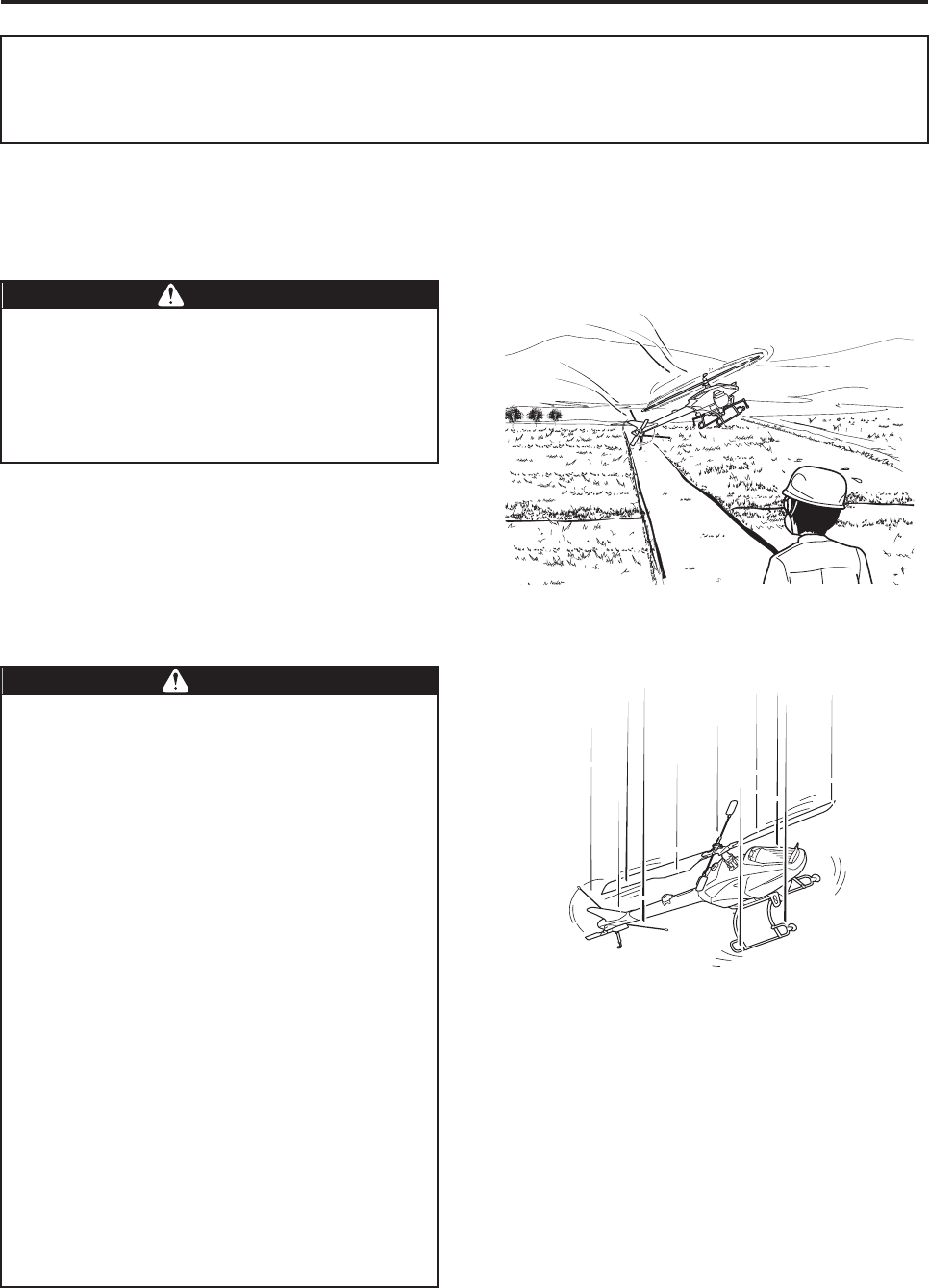
During radio signal interference, never
approach the helicopter until the main rotor
stops rotating completely, and the engine
has come to a complete stop. If there are any
people in the area, promptly instruct them to
go away.
DDANGER
●Do not fly at high altitudes higher than 3 to
4 meters (above ground or crop). In the
failsafe mode, the engine will stop auto-
matically after the allowable time, which
has been preset for safety, has elapsed.
Flying at an altitude that is higher than
necessary will cause the helicopter to drop
suddenly during an automatic descent in
the failsafe mode.
●The automatic control in the failsafe mode
varies depending on the GPS reception
conditions (see the next page and thereaf-
ter).
●Be sure to adhere to the indicated
“Actions”. Failure to take appropriate
actions can cause the helicopter, after
recovering from a radio signal interfer-
ence, to make an unexpected move or sud-
den descent, which can lead to accidents.
●Verify the cause of the radio signal inter-
ference, and never perform subsequent
flights until the cause has been eliminated.
Failure to observe this precaution can
cause the helicopter to become inoperable
again, which can lead to accidents.
WWARNING
Part Names and Functions
3-14
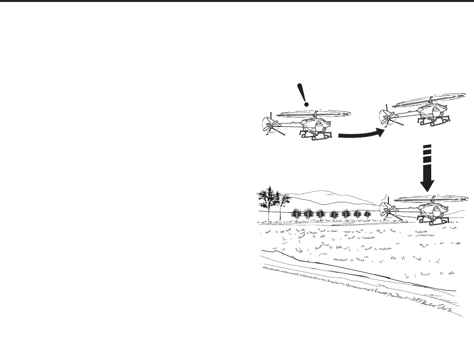
●Automatic control (operation) in the failsafe
mode when GPS reception is favorable
1When a radio signal interference occurs, the red
and yellow warning lamps will rapidly illuminate
alternately, and automatically effect brake con-
trol. The helicopter will hover (for approximately
10 seconds), and will automatically start a slow
descent.
If the operating radio signals recover during the
descent, the control will switch automatically to
operator operation. Therefore, calmly set the
sticks on the transmitter to their neutral (center)
position, and wait for the recovery.
2If the helicopter makes an emergency landing
because the radio signals did not recover, the
engine will stop approximately 15 seconds later.
The helicopter could topple, depending on the
terrain on which it has descended, weather con-
ditions, or flight conditions. If the helicopter top-
ples, never approach it until the engine has
come to a stop.
3After the emergency landing, place the throttle
stick in its slowest position, and wait for the radio
signals to recover or the engine to stop.
4If the radio signals remain unrecovered after the
failsafe mode (radio signal interference) is
tripped, and the helicopter cannot determine
whether it has landed, the engine will stop auto-
matically approximately 60 seconds later.
Wait until the main rotor completely stops rotat-
ing before approaching the helicopter and turn-
ing the main switch OFF.
Hover, then
descend slowly
Brake control
Radio signal
interference!
Part Names and Functions
3-15
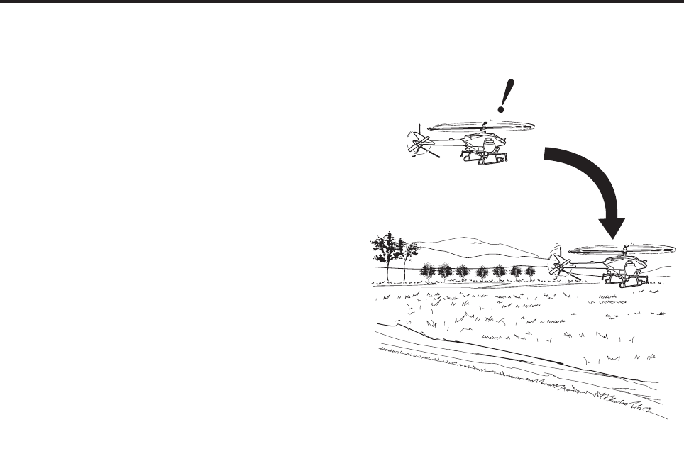
●Automatic control (operation) in the failsafe
mode when GPS reception is poor
1When radio signal interference occurs, the red
and yellow warning lamps illuminate alternately
at a quick pace, and the system forces the heli-
copter to descend rapidly. If the operating radio-
waves recover during descent, the control will
switch automatically to operator control. There-
fore, calmly set all the sticks on the transmitter in
their neutral (center) position and wait for the
recovery.
2If the helicopter makes an emergency landing
because the radio signals did not recover, the
engine will stop in approximately 10 to 15 sec-
onds.
The helicopter could topple, depending on the
terrain on which it has descended, weather con-
ditions, or flight conditions. If the helicopter top-
ples, never approach it until the engine has
come to a stop.
3After the emergency landing, place the throttle
stick in its slowest position, and wait for the radio
signals to recover or the engine to stop.
4If the radio signals do not recover after 15 sec-
onds have elapsed from the time the failsafe
mode (radiowave interference) has been tripped,
the engine will stop automatically even if the heli-
copter does not make an emergency landing.
5If the helicopter makes an emergency landing,
wait until the main rotor stops rotating before
approaching the helicopter and turning the main
switch OFF.
Radio signal interference!
Quick descent
Part Names and Functions
3-16
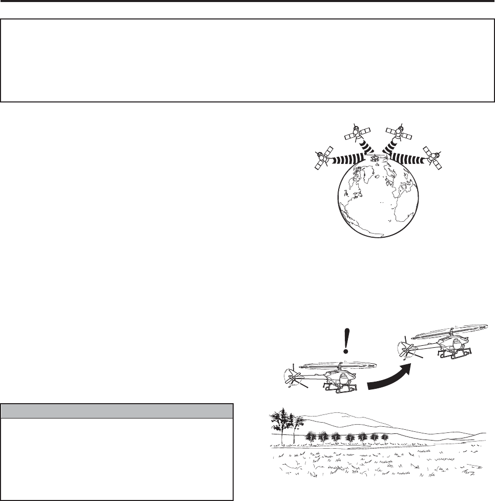
The GPS-based speed control functions by receiv-
ing radio signals from 4 or more satellites. This con-
trol might become unusable, depending on the
surrounding environment, terrain, weather condi-
tions, time of the day, or other reasons.
If GPS reception becomes poor while using the
GPS-based speed control flight mode, the safety
function will cause the yellow warning lamp to flash
irregularly, automatically effecting the control (oper-
ation) or switching the flight mode as described
below. Thoroughly familiarize yourself with this
function, and take appropriate actions.
When GPS reception becomes poor, the yellow
warning lamp will flash irregularly at the same time.
After the flight mode switches completely to pos-
tural control, the yellow lamp will change from irreg-
ular flashing to regular flashing. After that, the
control will transfer smoothly from speed control to
postural control.
Safety Functions and Actions in Case GPS
Reception Becomes Poor While Flying Under
Speed Control
If the yellow lamp transfers to regular flash-
ing, the flight mode will not revert to speed
control even if GPS reception improves. It
will revert if the GPS switch is turned back
ON after GPS reception improves.
ON → OFF → ON
NNOTICE
Poor GPS reception!
Transferring grad-
ually to postural
control
Part Names and Functions
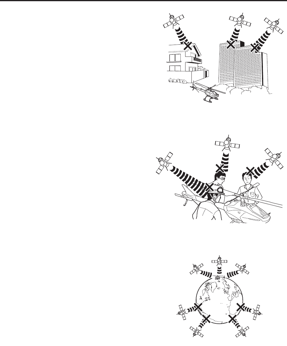
3-17
The reception of GPS radiowaves can become poor
due to the conditions described below or other rea-
sons.
1Presence of obstacles near the location of the
flight, such as mountains, trees, or buildings.
2There are people around the antenna.
3The number of satellites transmitting radio sig-
nals diminishes, because of the time of the day.