Futaba L35-N4581 Radio Control Transmitter User Manual
Futaba Corporation Radio Control Transmitter
Futaba >
Contents
- 1. user manual I
- 2. user manual II
- 3. user manual III
user manual III
Simple Maintenance
7-8
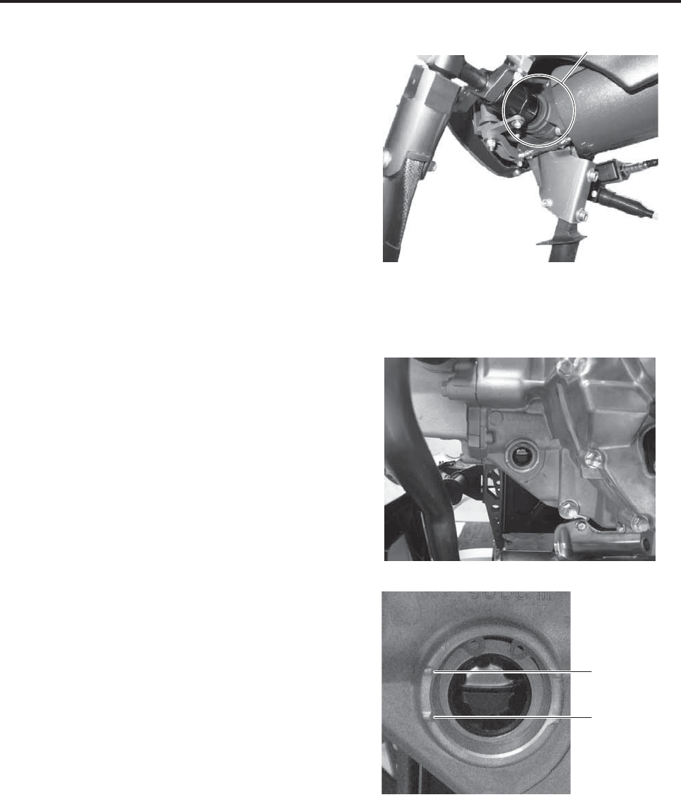
5Tail transmission
●Check that there is no oil leakage.
6Check engine oil level
●Check the oil level on the level gauge when the
engine is cold or 3 or more minutes have
elapsed after stopping the engine. If the oil is
more than the maximum level or less than the
minimum level, contact your dealer.
Tail transmission
Maximum
level
Minimum
level
Simple Maintenance
7-9
4. Main head area inspection (before and after)
Before performing this inspection, turn OFF both
the main switch for the helicopter and the power
switch for the transmitter.
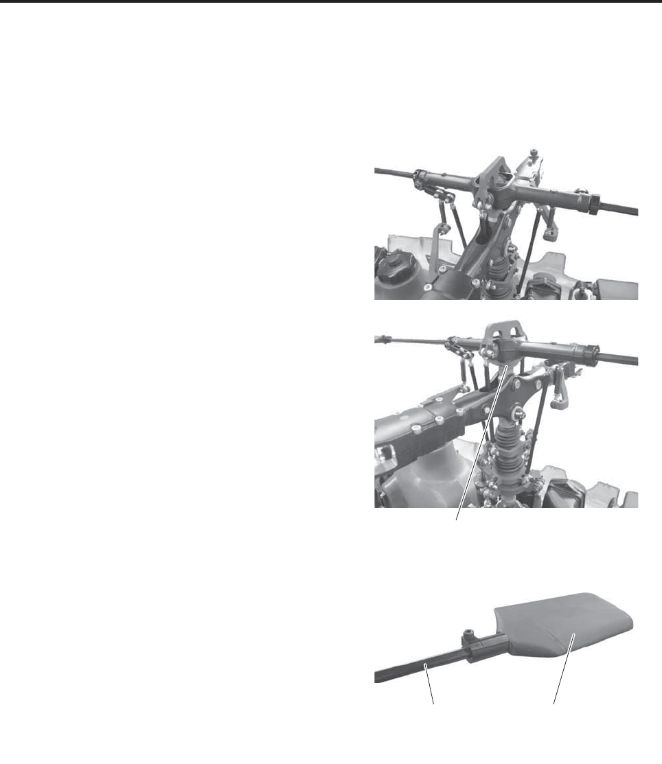
1Stabilizer
●Check the stabilizer for any deformation.
●Check that the stabilizer blade and stabilizer bar
are installed securely, without any looseness.
●Check that the stabilizer bar does not wobble in
axial direction.
●Check the portion that mounts to the main mast
for any looseness.
Main mast
Stabilizer bladeStabilizer bar
Simple Maintenance
7-10
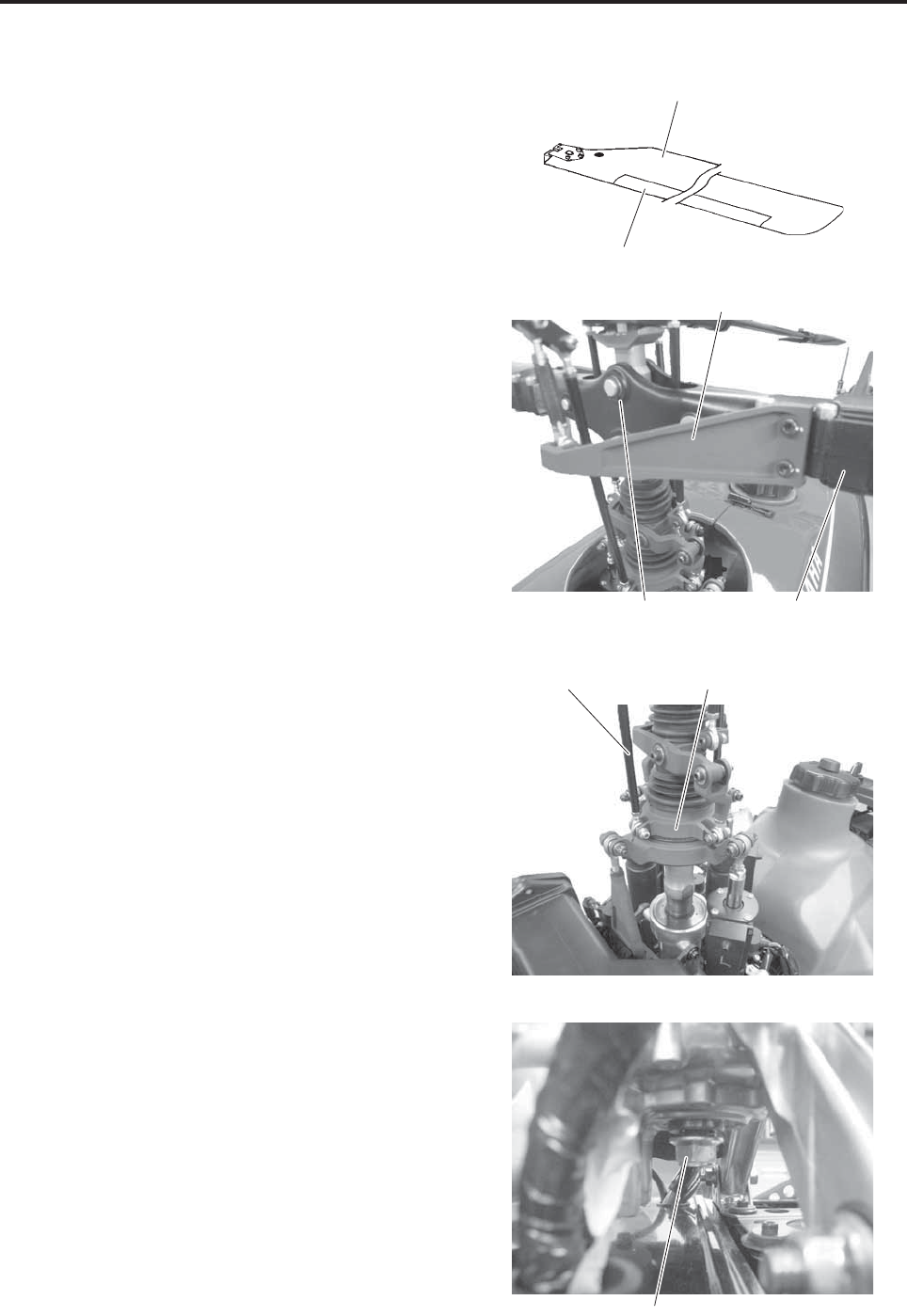
2Main rotor, yoke, blade holder
●Check the main rotor blades for cracks or chip-
ping.
* Contact your dealer if you see any cracks in
the painted surface.
●Check that the cushion tape is not peeling or
deteriorated.
* Excessive peeling can adversely affect flight.
●Blade edge wear inspection
* Contact your dealer if you see excessive
wear.
●Check the yoke and blade holder for any defor-
mation or cracks.
●Check the pitch arm for any deformation.
●Check that the pitch arm and blade holder are
installed without any looseness or wobble.
3Swash plate and linkage inspection
●Check that the swash plate and linkage (rod) are
installed without any wobble.
●Check the installed areas for any cracks or defor-
mation.
4Main mast
●Check the main mast retaining nuts for any
looseness.
Main rotor
Cushion tape
Pitch arm
Blade holder
Yo k e
Swash plateLinkage
Main mast retaining nut
Simple Maintenance
7-11
5. Tail body area inspection (before and after)
Before performing this inspection, turn OFF both
the main switch for the helicopter and the power
switch for the transmitter.
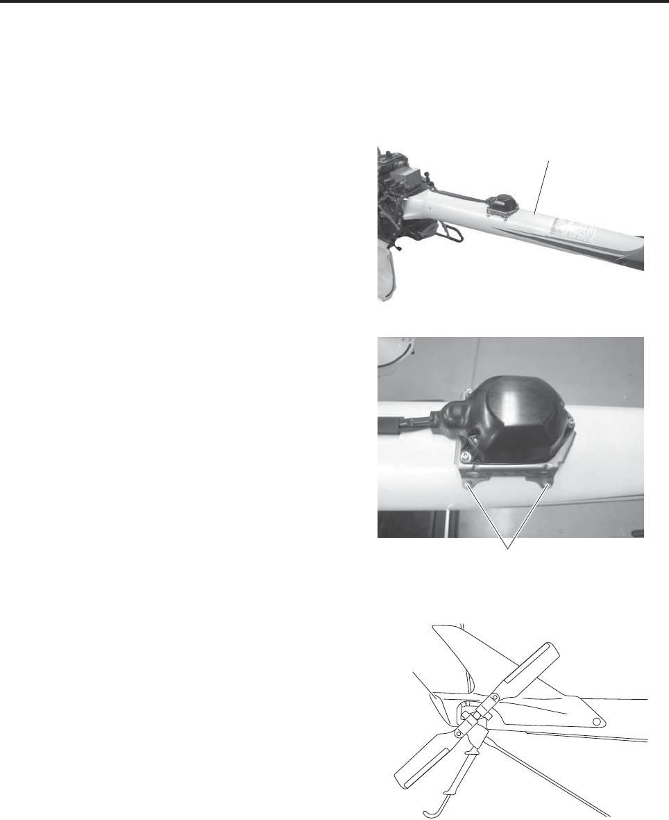
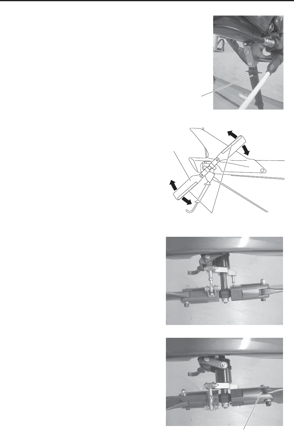
1Tail body
●Check the tail body for any damage.
●Check the tail body retaining bolts for any loose-
ness.
2Antenna
●For inspection details, refer to the section on
“Helicopter antenna inspection”.
3Tail cover
●Check the tail cover for any deformation or
cracks.
●Check that the tail cover is attached securely.
Tail body
Retaining bolt
Tail cover
Simple Maintenance
7-12
4Stone guard
●Check that it is attached securely.
●Check that there are no lamination cracks.
5Tail rotor
●Check the tail rotor blades for any damage.
●Check that the cushion tape is not peeling or
deteriorated.
●Check the blade edges for any damage.
●Check that it moves properly in the direction of
rotation.
●Check the bearing seal cap for any damage or
deterioration.
●Check the drag bolts and nuts for any damage.
●Move it manually to give it thrust, and check that
it moves smoothly.
Stone guard
Tail rotor
blade
Cushion tape
Bearing seal cap
Simple Maintenance
7-13
6. Drive shaft inspection (before and after)
Before performing this inspection, turn OFF both
the main switch for the helicopter and the power
switch for the transmitter.
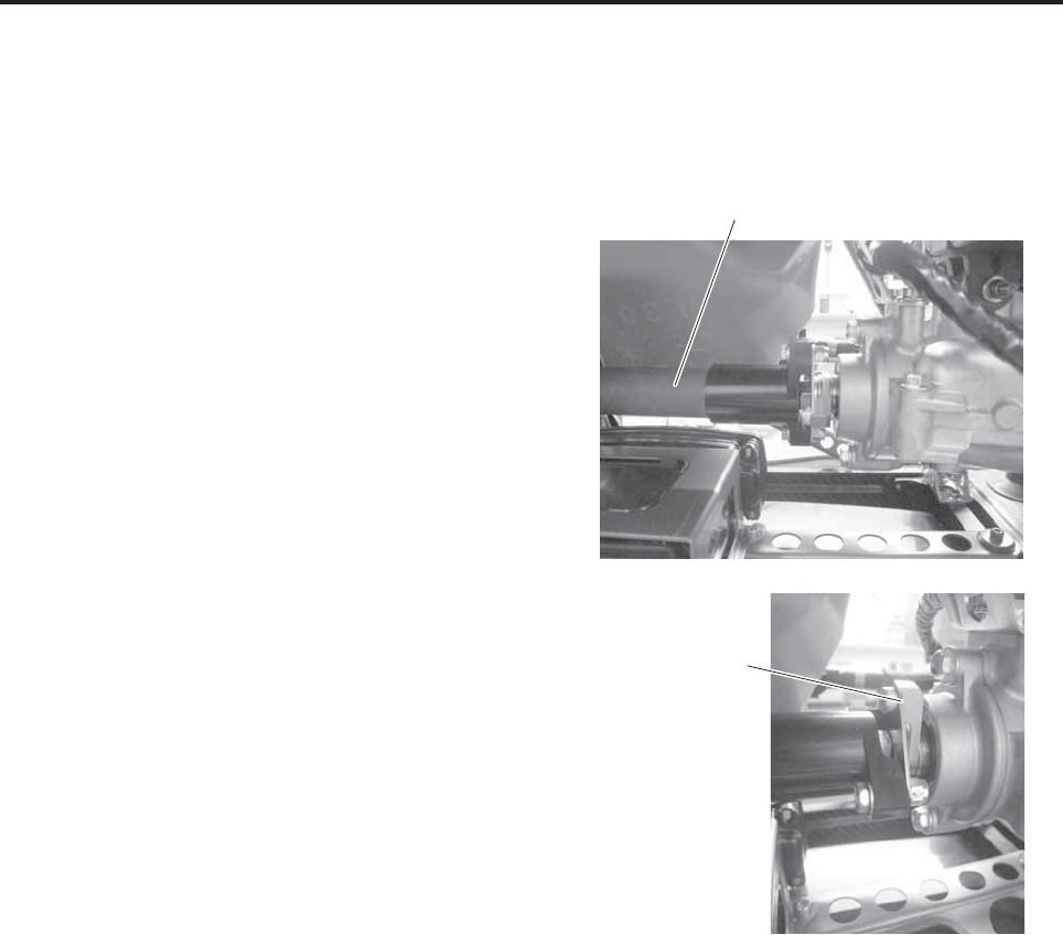
1Drive shaft and flange coupling
●Check the drive shaft for any damage.
●Check the portion that mounts to the flange cou-
pling for any problems.
Drive shaft
Flange coupling
Simple Maintenance
7-14
7. Servo inspection (before and after)
Inspect the servos and linkages for proper opera-
tion.
Before performing this test, turn ON both the main
switch for the helicopter and the power switch for
the transmitter.
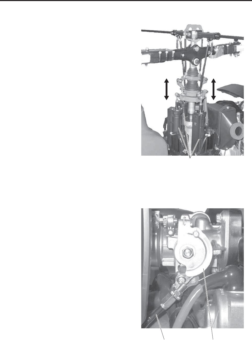
1Slide servo inspection
Slowly move the throttle, elevator, and aileron
sticks up and down and side-to-side. Inspect that
the servos and linkages move smoothly in uni-
son with the sticks. Also, inspect that the link-
ages do not wobble.
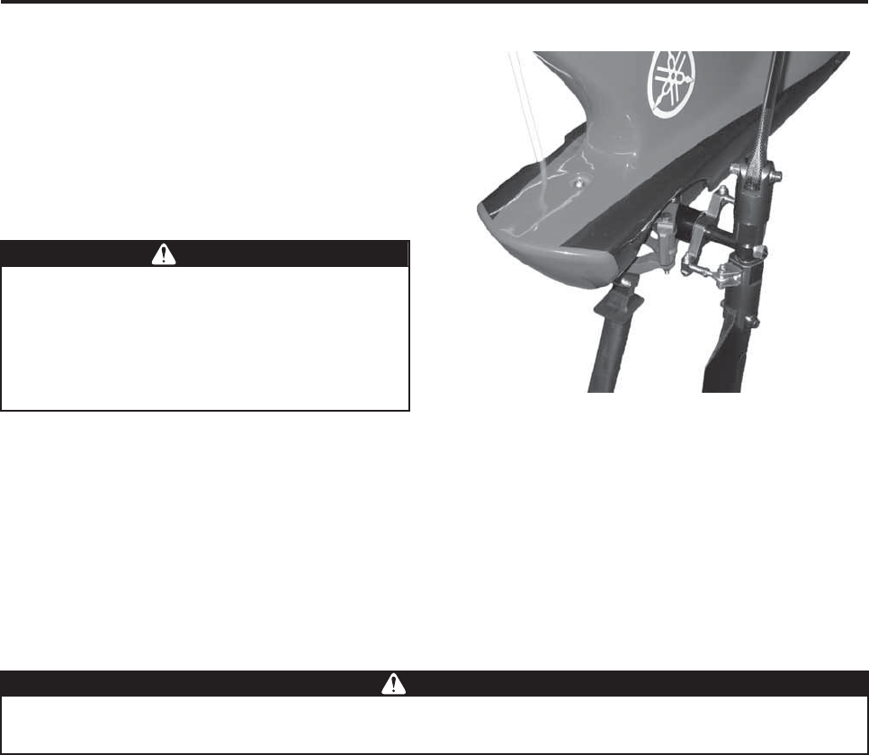
2Throttle inspection
●Throttle fully open, and fully closed
•With the throttle stick in its maximum posi-
tion, inspect that the throttle body pulley on
the throttle body moves to its fully open
position.
•With the throttle stick in its slowest position,
inspect that the throttle body pulley on the
throttle body moves to its fully closed posi-
tion.
●Throttle cable movement and play
• Move the throttle stick slowly up and down,
and inspect that the cable moves smoothly
without getting caught.
•With the throttle body pulley fully closed,
inspect that the cable has slight play.
* Check the throttle valve movement by way of
the pulley movement.
Slide servo
Throttle body pulley
Throttle cable
Simple Maintenance
7-15
3Rudder servo inspection
Slowly move the throttle and rudder sticks up
and down and side-to-side. Inspect that the ser-
vos and linkages move smoothly in unison with
the sticks. Also, inspect that the linkages do not
wobble.
If the servos operate improperly or the linkages
wobble, cancel the flight and ask your dealer for a
repair.
8. Self monitor inspection (before and after)
Inspect the self monitor for any abnormal condition.
Before performing this test, turn ON both the main switch for the helicopter and the power switch for the trans-
mitter.
Refer to page 3-10 for details.
If the lamp indications are improper, have them repaired at your dealer before your next flight.
9. Radio signal distance test (before)
Refer to page 4-10 for details.
●If the servos do not operate properly or the
linkages wobble, they can negatively affect
the control of the helicopter.
●If the throttle does not operate properly, it
can negatively affect engine control and
disable flight control.
WWARNING
Take appropriate actions if the self monitor indicates an error. Ignoring it and continuing to fly in
this manner will disable the flight control, which can lead to a serious accident.
WWARNING
Simple Maintenance
7-16
10. Electrical system inspection (before and after)
Before performing this inspection, turn OFF both
the main switch for the helicopter and the power
switch for the transmitter.
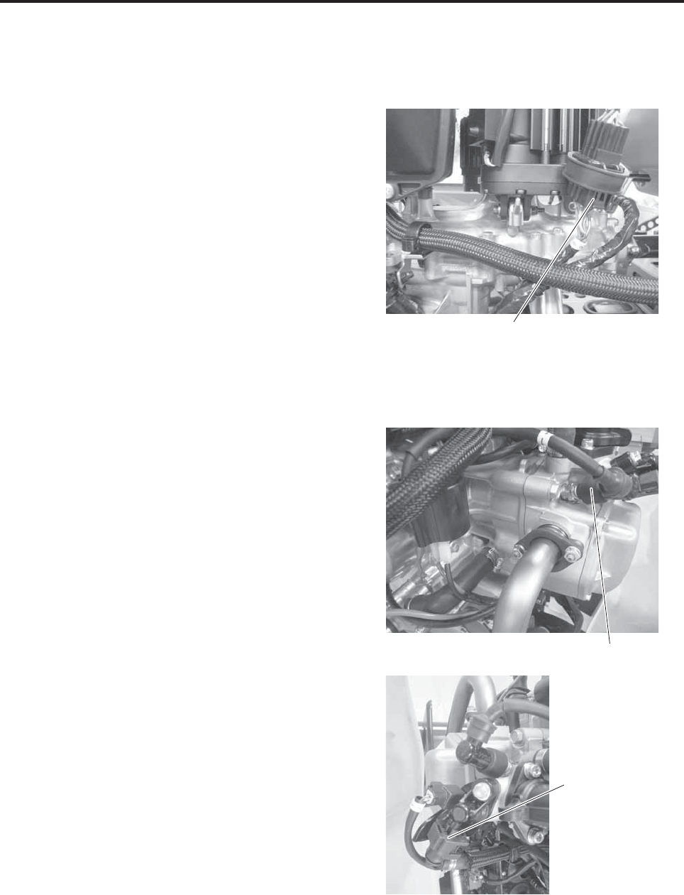
1Slide servo
●Check that the wiring harness coupler is
securely engaged.
2Cylinder
●Check that the spark plug cap is placed securely
over the plug.
●Check that the injector coupler is securely
engaged.
Coupler
Spark plug cap
Injector coupler
Simple Maintenance
7-17
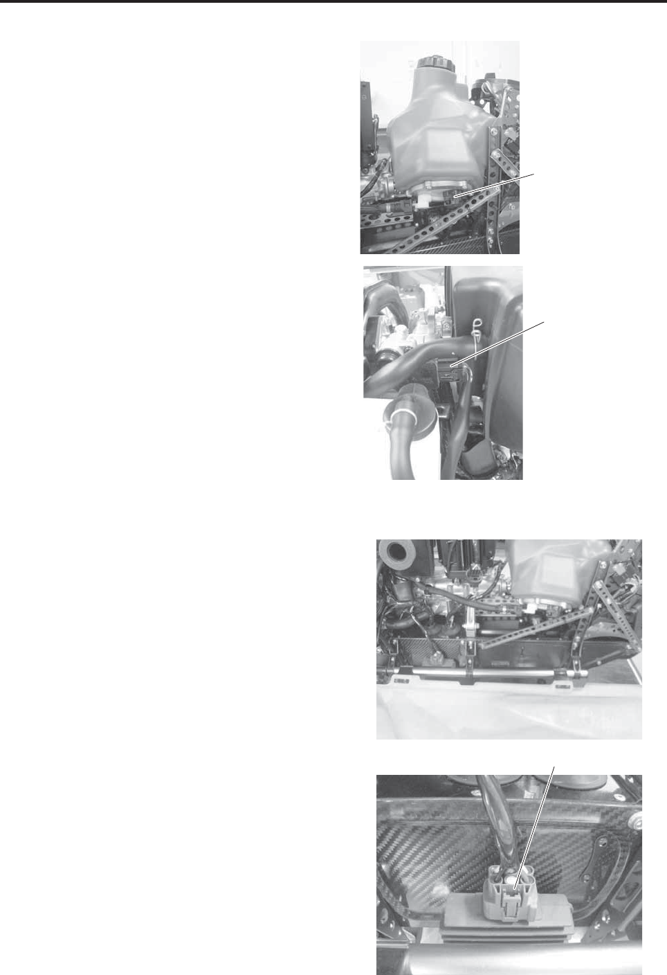
3Fuel Inspection
●Check that the fuel pump coupler is securely
engaged.
●Check that the throttle body sensor coupler is
securely engaged.
4Frame and electrical parts
●Check the frame for any deformation or cracks.
●Check that the regulator coupler is securely
engaged.
Fuel pump coupler
Sensor coupler
Coupler
Simple Maintenance
7-18
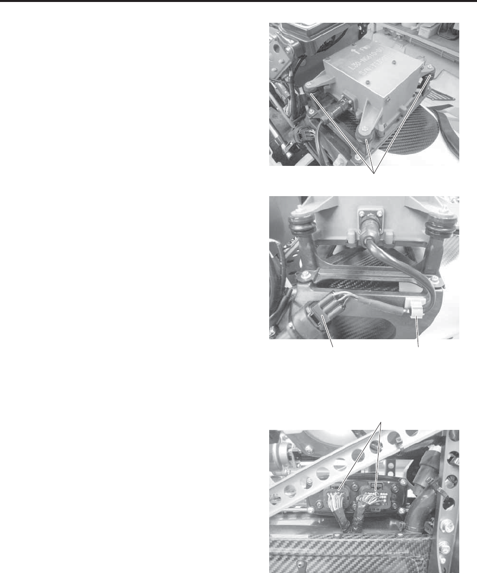
5Control unit
●Check the damper for damage and the retaining
nuts for looseness.
●Check that the coupler is securely engaged.
●Check that the wiring is properly secured with
gray clamps.
6Electrical system
●Check that the wires from the wiring harness are
free of wear or abrasion.
●Check that the wiring coupler is securely
engaged.
Clamp (gray)
Damper
Coupler
Coupler
Simple Maintenance
7-19
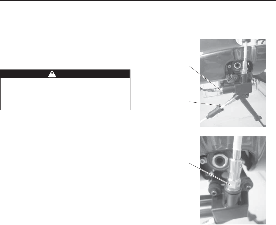
11. Helicopter antenna inspection (before and after)
Before performing this inspection, turn OFF both
the main switch for the helicopter and the power
switch for the transmitter.
●Check the antenna for any damage.
●Check that the antenna cable connector is
securely engaged.
●Check the antenna installation area for any rust.
Any looseness or rust in the antenna installa-
tion area will adversely affect the reception of
flight radio signals, which can lead to radio
signal interference during flight.
WWARNING
Connector
Antenna
Antenna installation
area

Proper Management
Storage Precautions .................................................................... 8-1
Daily storage procedure........................................................................................... 8-2
Long-term storage procedure .................................................................................. 8-2
Operating the helicopter after long-term storage ..................................................... 8-3
Other Types of Management ....................................................... 8-5
Transfer of product................................................................................................... 8-5
Disposal of product .................................................................................................. 8-5
Export control........................................................................................................... 8-5
8
8-1
Proper Management
This unmanned helicopter for industrial applications has been manufactured for the purpose of aerial applica-
tion of agricultural chemicals, fertilizers, and seeds.
Secure a storage location for the helicopter and its auxiliary devices, to prevent theft and illegal use outside of
its intended purpose, such as criminal acts.
To select a storage site, consider factors such as
sources of fire or spark, temperature, humidity,
dust, theft, and the presence of any stacked loads
in the area.
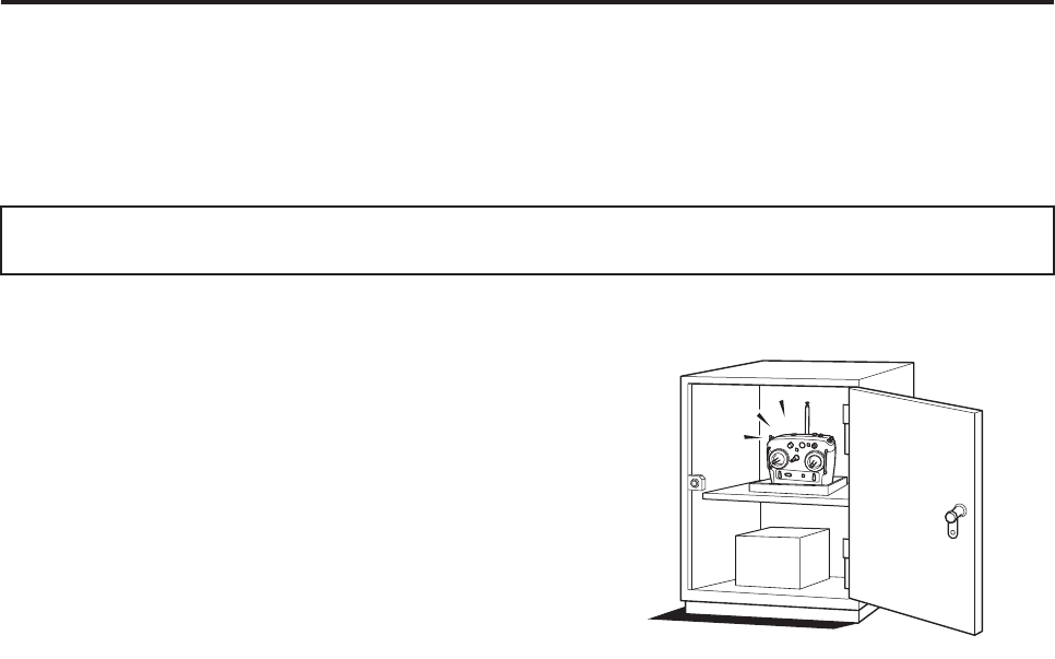
We recommend that you provide a dedicated cabi-
net for storing the auxiliary devices.
In addition to protecting the helicopter from damage
and theft, or the auxiliary devices from loss, these
measures will facilitate the monitoring of their main-
tenance conditions and ensure efficient preparation
for the next flight.
• Store the helicopter, rotors, and transmitters in
separate, lockable locations so that they will not
be stolen or subject to other criminal acts.
• If the helicopter is stolen, immediately file a theft
report with your local police department, followed
by a report to your dealer.
Storage Precautions
Proper Management
8-2
Daily storage procedure
1Perform post-flight inspections (Refer to pages
7-3 to 7-19) and record the results in the flight
log.
2Clean the helicopter. (Refer to page 6-1.)
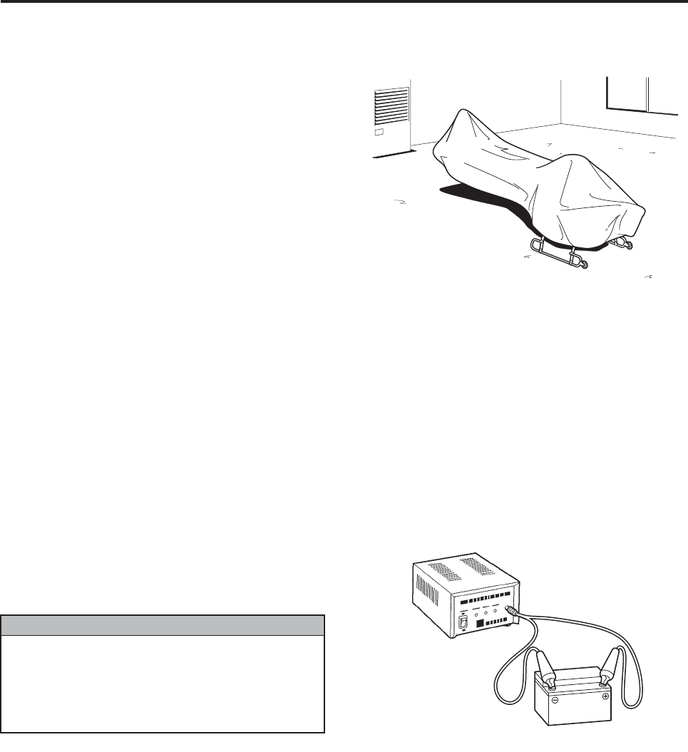
3Place the cover (sold separately) on the helicop-
ter, and store it indoors, in an area that is not
damp.
4Clean the flight transmitter and remove its bat-
tery. (Refer to page 7-2.)
Long-term storage procedure
If the helicopter will not be operated for a few
months, follow the storage procedure given below
in preparation for the subsequent operation.
1Perform a post-flight inspection (Refer to pages
7-3 to 7-19) and record the results in the flight
log.
2Clean the helicopter. (Refer to page 6-1.)
3Remove the battery from the helicopter and
charge it with a dedicated charger (sold sepa-
rately) (Refer to page 7-1.).
Store the charged battery in a cool, dark area,
and recharge it every 3 months.
4Fuel must be drained from the fuel tank. Request
this operation to be performed by your dealer.
5Place the cover (sold separately) on the helicop-
ter, and store it indoors, in an area that is not
damp.
6Clean the flight transmitter and remove its bat-
tery. Store the battery in a cool, dark area.
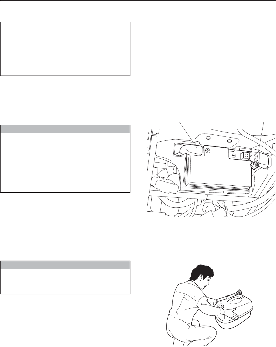
The proper procedure for removing the bat-
tery is to first disconnect the negative termi-
nal, followed by the positive terminal.
Reversing this order can cause a short circuit
in the battery.
NNOTICE
Proper Management
8-3
Operating the helicopter after long-term storage
To operate the helicopter after storing it for a few
months, perform the following preparations:
1Install fully charged batteries in the helicopter
and the flight transmitter, after making sure the
main switch on the helicopter is turned OFF.
2Pour fresh fuel in the fuel tank. (Refer to page 4-
4.)
●Have a periodic inspection performed on
the helicopter if you will be operating it
after prolonged storage of 1 year or more.
●If a deletion of registration was filed, apply
for a renewal registration.
●Contact your dealer for details.
TIP
●Do not interchange the cables to the posi-
tive and negative terminals of the battery,
as it can cause a fire or malfunction.
●The proper procedure for connecting the
battery is to first connect the positive ter-
minal, followed by the negative terminal.
Reversing this order can cause a short cir-
cuit in the battery.
NNOTICE
Positive terminal side
Connect the negative
terminal afterward.
Never use old leftover fuel.
This could cause the engine to start or oper-
ate poorly.
NNOTICE
Proper Management
8-4
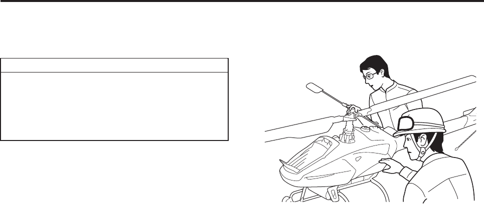
3Perform pre-flight inspections. (Refer to pages 7-
3 to 7-19.)
4Start the engine.
Repeat the cycle of operating the starter motor for 5
seconds and waiting 10 seconds, a few times. This
will allow the fuel to reach the carburetor and the
engine to start.
If the engine does not start within 5 seconds
after the starter switch is pressed, allow the
starter to rest for about 10 seconds. This is
done to allow the battery voltage to recover.
Then, press the starter switch again.
TIP
OK!
OK!

Proper Management
8-5
Transfer of product
When transferring the product to a third party, inform your dealer of it.
Disposal of product
Properly dispose of the helicopter, transmitters, sprayers, and batteries according to national laws and regula-
tions. Contact your dealer for details.
Export control
Other Types of Management

Product Management
About Warranty............................................................................ 9-1
Inspection Types and Descriptions.............................................. 9-2
Pre-flight inspection ................................................................................................. 9-2
Post-flight inspection................................................................................................ 9-3
30-hour free inspection ............................................................................................ 9-3
Periodic inspection................................................................................................... 9-3
9

9-1
Product Management
The warranty becomes valid after the dealer where the product was purchased fills out with required informa-
tion and stamps the warranty certificate. Malfunctions that occur during the warranty period will be repaired
free of charge, provided that the product is operated normally in accordance with the instructions in the oper-
ation manual. The warranty does not cover some items, even within the warranty period. For details, refer to
the warranty certificate.
About Warranty
Product Management
9-2
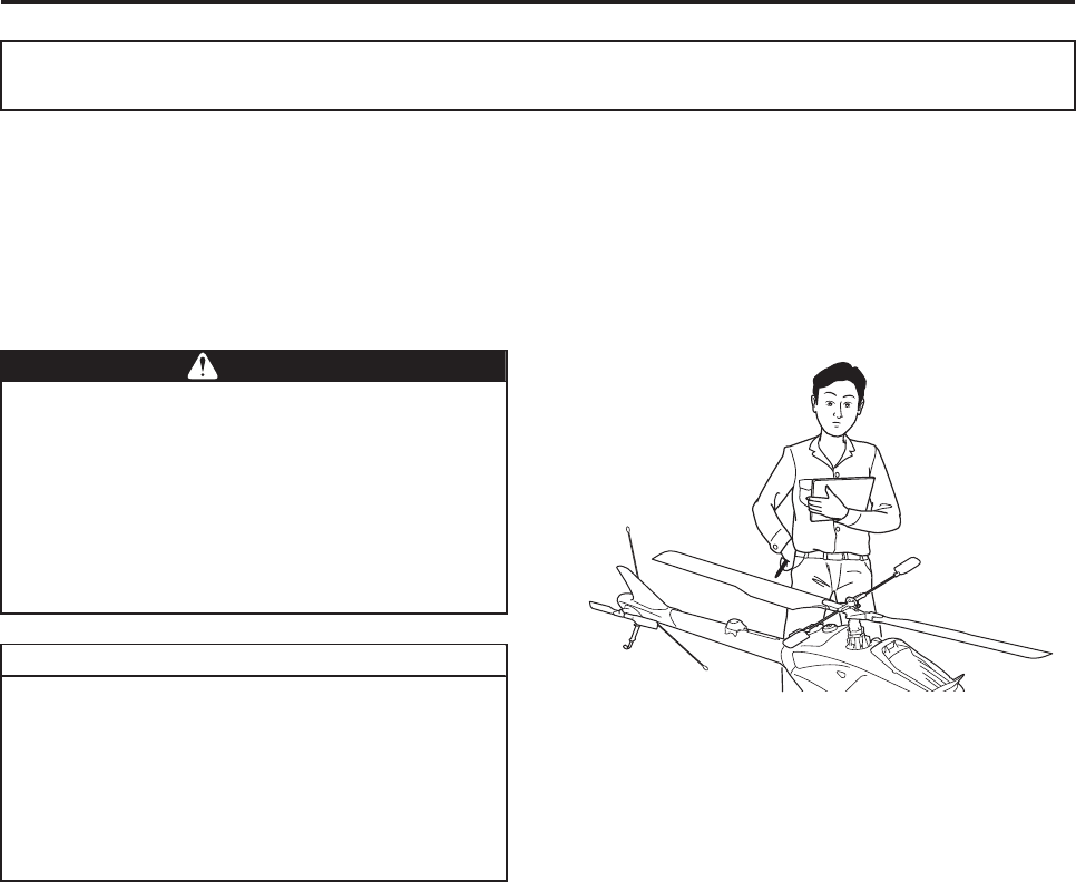
The prescribed types of inspections are described
below.
• Pre-flight and post-flight inspections are to be
performed by the operator.
• For the 30-hour free inspection and yearly peri-
odic inspection, contact your dealer or an autho-
rized service facility for Yamaha unmanned
helicopters for industrial applications.
A Yamaha-authorized service facility for unmanned
helicopters for industrial applications is a service
facility staffed by certified service technicians for
Yamaha industrial unmanned helicopters and
equipped with the prescribed service equipment.
Pre-flight inspection
Ensures that the helicopter and the auxiliary equipment are free of problems before a flight.
See pages 7-3 to 7-19 for details on the inspection.
Inspection Types and Descriptions
For the 30-hour free inspection, periodic
inspection, or general repair, contact your
dealer or an authorized service facility for
Yamaha unmanned helicopters for industrial
applications. Having the helicopter inspected
or serviced by a person who is not autho-
rized to service unmanned helicopters can
lead to a helicopter malfunction or accident.
●Do not fly or perform an aerial application
without having a yearly periodic inspec-
tion performed.
●Failure to perform the inspections
described below invalidates your product
warranty, so be sure to have them per-
formed.
WWARNING
TIP
Product Management
9-3
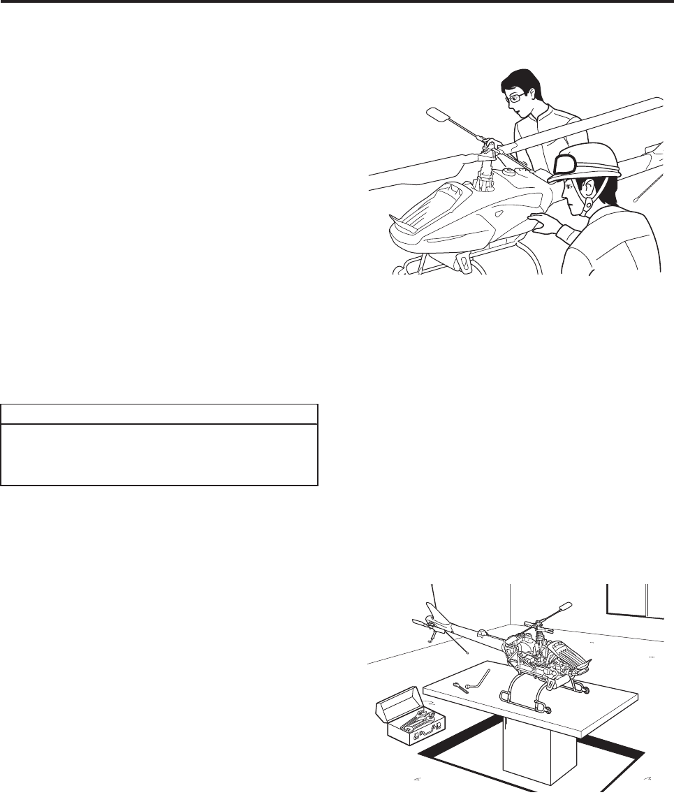
Post-flight inspection
Ensures that the helicopter and the auxiliary equip-
ment are free of problems after a flight.
See pages 7-3 to 7-19 for details on the inspection.
If a problem is detected, promptly contact your
dealer.
Record the results of the inspection on the flight
log. Failure to do so will invalidate your product war-
ranty.
30-hour free inspection
An inspection service performed after the delivery
of a new helicopter, when the hour meter indicates
a total of 30 hours of operation.
Failure to have this inspection performed will invali-
date your product warranty.
Periodic inspection
An inspection service performed once a year at an
authorized dealer or service facility. The service
includes testing for durability and performance of
the helicopter.
OK!
OK!
Expendable items such as oil or other
replacement parts are payable by the cus-
tomer.
TIP

Troubleshooting
Engine........................................................................................ 10-1
Starter motor does not operate. ............................................................................. 10-1
Unable to start the engine...................................................................................... 10-1
Engine speed does not increase............................................................................ 10-2
Engine lacks power................................................................................................ 10-2
Engine overheating ................................................................................................ 10-3
Coolant gushed out of the recovery tank ............................................................... 10-3
Helicopter emits a burning smell............................................................................ 10-3
Engine idle is unstable ........................................................................................... 10-4
Engine idle is too high............................................................................................ 10-4
Engine speed does not decrease after landing...................................................... 10-4
Exhaust emits excessive smoke ............................................................................ 10-4
Engine emits noise................................................................................................. 10-5
Engine loses oil...................................................................................................... 10-5
Helicopter................................................................................... 10-6
Helicopter vibrates ................................................................................................. 10-6
Helicopter cannot take off ...................................................................................... 10-6
Helicopter makes noise during takeoff................................................................... 10-6
Helicopter descends after takeoff .......................................................................... 10-6
Helicopter moves considerably after takeoff .......................................................... 10-6
Helicopter drifts in one direction............................................................................. 10-7
Helicopter descends when flare (brake) is applied ................................................ 10-7
Helicopter moves considerably in rudder direction
when flare (brake) is applied.................................................................................. 10-7
Warning Lamp Indications ......................................................... 10-8
Warning lamp illuminates or flashes ...................................................................... 10-8
The warning lamp (regular flashing of red lamp) remains lit
even after refueling ................................................................................................ 10-8
Speed Control............................................................................ 10-8
Speed control is unusable...................................................................................... 10-8
When speed control is used, the helicopter moves arbitrarily................................ 10-8
10

Flight Transmitter....................................................................... 10-9
Power lamp and battery lamp (green) do not illuminate ........................................ 10-9
Transmitter battery state-of-charge warning .......................................................... 10-9
Transmitter battery’s usable range is too short...................................................... 10-9
Dropped the transmitter on the ground .................................................................. 10-9
Dropped the transmitter in water............................................................................ 10-9
The sprayer cannot be turned ON or OFF at the flight transmitter. ....................... 10-9
The transmitter sounded 4 beeps repeatedly. ..................................................... 10-10
Sprayer .................................................................................... 10-10
Liquid sprayer problems....................................................................................... 10-10
Granular sprayer problems .................................................................................. 10-10

10-1
Troubleshooting
The problems listed here can be handled primarily
by the user.
Problems or causes that are not listed here are
handled by your dealer. If such problems occur,
cancel the flight and contact your dealer to have the
helicopter inspected and repaired.
Starter motor does not operate
Unable to start the engine
●Make sure to follow the instructions given
in the “User Action” column, and do not
take any actions that are not documented.
●If you have any questions, be sure to con-
tact your dealer. If an inspection, adjust-
ment, or part replacement is performed by
a person who does not possess the know-
how and proficiency to service the heli-
copter, it could lead to a serious accident.
WWARNING
Engine
Main Cause User Action
1 Main switch on the helicopter is not turned ON. Turn the main switch of the helicopter ON.
2 The power switch of the flight transmitter is not ON. Turn the power switch of the flight transmitter ON.
3The operation of the engine stop switch on the flight trans-
mitter has not been checked.
If the blue flight lamp is not illuminated, the starter
motor will not operate even if you press the starter
switch. Check the operation of the engine stop switch.
4 The flight switch of the flight transmitter is not in START. Place the flight switch of the flight transmitter to START.
5The throttle stick on the flight transmitter is not in the
SLOWEST position.
When the blue flight button does not illuminate, the
throttle stick on the flight transmitter may not be in
the SLOWEST position. Set the throttle stick to the
SLOWEST position.
6 Helicopter battery failure or loose terminals Securely tighten the battery terminals, or contact
your dealer.
7 Helicopter battery failure Charge the battery on a dedicated charger, or
replace it.
8Pressing the starter button causes the blue flight lamp to
flash.
Check the content displayed on the self monitor, and
request your dealer for a repair. Even if the afore-
mentioned check does not reveal the cause, contact
your dealer.
Main Cause User Action
1 There is no fuel. Pour fresh fuel in the tank.
2 The fuel pump is not operating.
If the fuel pump does not operate with the helicopter
main switch turned ON, a disconnected wiring cou-
pler or other malfunctions may be possible. In this
case, contact your dealer.
3 Poor quality fuel (old fuel). Contact your dealer.
4 The fuel is dirty (fuel filter is clogged). Immediately stop the flight and request a repair by
your dealer.
5 The spark plugs are faulty. Immediately stop the flight and request a repair by
your dealer.
6 The spark plug caps are improperly installed. Install the spark plug caps properly.
7 The starter motor spins slowly. Recharge the helicopter battery with a dedicated
charger.

Troubleshooting
10-2
Engine speed does not increase
Engine lacks power
Main Cause User Action
1 The flight switch of the transmitter is not in FLIGHT.
With the throttle stick on the transmitter in the
SLOWEST position, set the flight switch to FLIGHT.
* The helicopter cannot fly unless the blue warning
lamp on the helicopter is off.
2 The fuel is dirty (fuel filter continues to be clogged). Immediately stop the flight and request a repair by
your dealer.
3 Air cleaner element is dirty and clogged. Immediately stop the flight and request a repair by
your dealer.
4 The spark plugs are faulty. Immediately stop the flight and request a repair by
your dealer.
5Warning lamp is tripped
(red lamp flashing irregularly, or illuminating).
If the red warning lamp is flashing irregularly, imme-
diately land the helicopter. Check the contents dis-
played on the self monitor, and contact your dealer
for a repair. If the red lamp illuminates for reasons
other than speeding, land the helicopter in a safe
area, check the contents displayed on the self moni-
tor, and contact your dealer for a repair.
Main Cause User Action
1 Engine Overheating Immediately stop the flight and check the contents of
“Engine overheating”.
2 The spark plugs are faulty. Immediately stop the flight and request a repair by
your dealer.
3 Air cleaner element is dirty and clogged Immediately stop the flight and request a repair by
your dealer.
4 Injector malfunction Immediately stop the flight and request a repair by
your dealer.
5 The fuel is dirty (fuel filter is clogged). Immediately stop the flight and request a repair by
your dealer.

Troubleshooting
10-3
Engine overheating
Coolant gushed out of the recovery tank
Helicopter emits a burning smell
Main Cause User Action
1 Coolant leakage, or insufficient coolant
Replenish the coolant.
If the coolant is leaking, contact your dealer for a
repair.
2 A specified coolant is not being used. Be sure to use a specified product. In this case, con-
tact your dealer.
3 The radiator is dirty, or the fins are clogged. Clean the radiator.
4 Thermostat failure Immediately stop the flight and request a repair by
your dealer.
5 Engine running poorly Immediately stop the flight and request a repair by
your dealer.
6 Excessive engine load Reduce the payload.
Main Cause User Action
1
Engine overheating
(The warning lamp may operate, depending on the tem-
perature.)
Immediately stop the flight and check the contents of
the previous section on “Engine overheating”.
2
Gradual loss of coolant
With normal use, a small amount of coolant may escape
through the overflow pipe.
If the coolant gets below the LOW level of the recov-
ery tank, contact your dealer for a repair.
Main Cause User Action
1 Engine overheating Immediately stop the flight and check the contents of
“Engine overheating”.
2 Oil leakage Immediately stop the flight and request a repair by
your dealer.
3Wires are burned Immediately stop the flight and request a repair by
your dealer.

Troubleshooting
10-4
Engine idle is unstable
Engine idle is too high
Engine speed does not decrease after landing
Exhaust emits excessive smoke
Main Cause User Action
1 The spark plugs are faulty. Immediately stop the flight and request a repair by
your dealer.
2 The spark plug caps are improperly installed. Install the spark plug caps properly.
3 Excessive deviation of valve clearance Immediately stop the flight and request a repair by
your dealer.
Main Cause User Action
1 Adjustment failure Immediately stop the flight and request a repair by
your dealer.
2 A control system failure is possible.
Immediately stop the flight, check the contents dis-
played on the self monitor, and request a repair by
your dealer.
Main Cause User Action
1
The landing speed control does not disengage.
(This occurs rarely when the helicopter is brought to land
so slowly that no shock whatsoever is felt.)
When using postural control to land: set the throttle
stick to the SLOWEST position for 10 seconds.
When using speed control to land: Turn GPS
switch OFF to change to postural control. Then, set
the throttle stick to the SLOWEST position for 10 sec-
onds.
Main Cause User Action
1Wrong fuel Check whether you are using pre-mix fuel for the
RMAX model.
2Engine internal failure
(If no wrong fuel is used)
Immediately stop the flight and request a repair by
your dealer.

Troubleshooting
10-5
Engine emits noise
Engine loses oil
Main Cause User Action
1 Engine is damaged internally or lubricated insufficiently. Immediately stop the flight and request a repair by
your dealer.
Main Cause User Action
1 Oil running down through intake and exhaust valves
It is normal for the engine to consume about 80 to
100 cc of oil after 100 hours of operation. If it con-
sumes more than that, contact your dealer.
2 Oil escaping through piston rings
It is normal for the engine to consume about 80 to
100 cc of oil after 100 hours of operation. If it con-
sumes more than that, contact your dealer.

Troubleshooting
10-6
Helicopter vibrates
Helicopter cannot take off
Helicopter makes noise during takeoff
Helicopter descends after takeoff
Helicopter moves considerably after takeoff
Helicopter
Main Cause User Action
1 Main rotor blades are positioned improperly. Install the rotor blades by matching their color marks.
2Main rotor or tail rotor retaining bolts are tightened improp-
erly.
Follow the specified tightening procedure to tighten
the bolts.
3 Main rotor or tail rotor is damaged. Immediately stop the flight and request a repair by
your dealer.
4 Cushion tape has peeled from the main rotor or tail rotor. Immediately stop the flight and request a repair by
your dealer.
5 Tracking of the main rotor or tail rotor is faulty. Immediately stop the flight and request a repair by
your dealer.
6 Main rotor or tail rotor is unbalanced. Immediately stop the flight and request a repair by
your dealer.
7 Chemical tank is improperly installed. Securely install the chemical tank.
Main Cause User Action
1 Engine speed does not increase. Immediately stop the flight and check the section on
“Engine speed does not increase”.
2 Engine lacks power. Immediately stop the flight and check the section on
“Engine lacks power”.
Main Cause User Action
1 Bolts of parts are loose. Immediately stop the flight and request a repair by
your dealer.
2 The noise does not go away after a takeoff. Immediately stop the flight and request a repair by
your dealer.
Main Cause User Action
1 Engine lacks power. Immediately stop the flight and check the section on
“Engine lacks power”.
2 Payload is excessive. Reduce the payload.
Main Cause User Action
1 The transmitter was operated suddenly after takeoff. Do not operate suddenly.

Troubleshooting
10-7
Helicopter drifts in one direction
Helicopter descends when flare (brake) is applied
Helicopter moves considerably in rudder direction when flare
(brake) is applied
Main Cause User Action
1 Trim is adjusted improperly. Adjust the trims on the flight transmitter.
Main Cause User Action
1 Rotor lift decreased due to an abrupt flare operation. Do not operate flare suddenly.
2 Payload is excessive. Reduce the payload.
Main Cause User Action
1 Helicopter loses balance due to an abrupt flare operation. Do not operate flare suddenly.

Troubleshooting
10-8
Warning lamp illuminates or flashes
The warning lamp (regular flashing of red lamp) remains lit even
after refueling
Speed control is unusable
When speed control is used, the helicopter moves arbitrarily
Warning Lamp Indications
Main Cause User Action
1 Identifiable through the warning lamp operation pattern.
Immediately stop the flight and take appropriate
actions in accordance with the contents of “Various
Types of Warning (Warning, Indication) and Actions”.
Main Cause User Action
1 Fuel temperature is too high
The fuel in the fuel tank gets hot under a scorching
sun. Therefore, keep the fuel tank in a shaded area.
The sensors may operate improperly, depending on
the temperature (they revert to normal when the tem-
perature drops).
2 Possibility of state-of-charge warning of transmitter battery
The state-of-charge warning of the transmitter bat-
tery has the same contents. (The transmitter beeps 4
times (*).) Immediately replace it with a fully charged
transmitter battery.
(* Three sets of 4 beeps, a 4-second pause, and 3
sets of 4 beeps repeated thereafter.)
Speed Control
Main Cause User Action
1 GPS radio signals are not properly received.
Speed control is disabled in this condition. It may be
a temporary matter caused by the surrounding con-
ditions. If it does not revert to normal, contact your
dealer. Moreover, even if it does not revert to normal,
the helicopter can be flown under postural control.
Main Cause User Action
1
Proper GPS radio signals are not being received due to a
poor location of the GPS satellites or the presence of
obstacles.
Immediately turn OFF the GPS switch to see if the
helicopter becomes stable. Often, these situations
are temporary. Wait a while and turn the GPS switch
back ON.

Troubleshooting
10-9
Power lamp and battery lamp (green) do not illuminate
Transmitter battery state-of-charge warning
The warning lamp operates (regular flashing), the transmitter’s power lamp changes from green to red illumi-
nation, the battery monitor lamp changes from green to red flashing, and the warning buzzer repeats 4 beeps
3 times, pauses 4 seconds, and repeats 4 beeps 3 times, and so on.
Transmitter battery’s usable range is too short
Dropped the transmitter on the ground
Dropped the transmitter in water
The sprayer cannot be turned ON or OFF at the flight transmitter
*: The sprayer transmitter is sold separately.
Flight Transmitter
Main Cause User Action
1 Transmitter’s internal failure Immediately stop the flight and request a repair by
your dealer.
Main Cause User Action
1 Low state-of-charge of battery
Replace with a fully charged battery.
(If a warning is issued even once, immediately
replace with a fully charged battery.)
2Warning lamp operation
Replace with a fully charged battery.
(If a warning is issued even once, immediately
replace with a fully charged battery.)
Main Cause User Action
1 Battery life or malfunction Replace the battery.
Main Cause User Action
1Immediately stop the flight and request an inspection
by your dealer.
Main Cause User Action
1Immediately stop the flight and request an inspection
by your dealer.
Main Cause User Action
1The sprayer transmitter (*) has power, and the sprayer
switch is OFF. Turn OFF the power to the sprayer transmitter (*).

Troubleshooting
10-10
The transmitter sounded 4 beeps repeatedly
Liquid sprayer problems
Refer to the operation manual for the liquid sprayer
Granular sprayer problems
Refer to the operation manual for the granular sprayer
Main Cause User Action
1 Transmitter’s internal failure
Immediately stop the flight, check the contents dis-
played on the self monitor, and request a repair by
your dealer.
Sprayer

Index
Numerics
30-hour free inspection ..................................... 9-3
B
Basic requirements ........................................... 1-2
C
Chemical requirements ................................... 1-11
Chemical tank ................................................... 4-6
Control panel ..................................................... 3-2
flight lamp ................................................... 3-2
main switch ................................................. 3-2
starter switch .............................................. 3-2
Coolant inspection ............................................. 7-6
D
Data List ............................................................ 2-1
Dimensions ....................................................... 2-2
Drive shaft inspection ...................................... 7-13
E
Electrical system inspection ............................ 7-16
Engine
Starting ....................................................... 5-3
Stopping ..................................................... 5-9
Export control .................................................... 8-5
F
Flight modes ...................................................... 5-8
Flight requirements ........................................... 1-7
Flight transmitter ............................................... 3-4
basic operation ........................................... 3-5
battery monitor lamp ................................... 3-9
battery replacement .................................... 4-2
battery storage ............................................ 4-2
charging the battery .................................... 4-1
engine stop switch ...................................... 3-4
flight switch ................................................. 3-4
GPS switch ................................................. 3-7
inspection ................................................... 7-4
rotor brake switch ....................................... 3-4
spray switch ................................................ 3-8
stick basic operation and
helicopter movement ............................ 3-5
trim lever basic operation and
helicopter movement ............................ 3-6
Flying precaution ............................................... 5-1
Frequency settings and checks ......................... 3-8
Fuel and refueling ............................................. 4-4
Fuel inspection .................................................. 7-5
G
General aerial application pattern ................... 5-11
GPS
Safety functions in case reception
becomes poor ..................................... 3-16
H
Helicopter antenna inspection ......................... 7-19
Helicopter exterior parts (names) ...................... 3-1
Helicopter interior parts (names) ....................... 3-3
Helicopter requirements .................................... 1-5
M
Main head area inspection ................................ 7-9
Main rotor
inspection .................................................. 4-12
installation and removal ............................ 4-11
O
Oil inspection ..................................................... 7-6
Operator requirements ...................................... 1-3
P
Periodic inspection ............................................ 9-3
Post-flight cleaning and servicing ...................... 6-1
non-washable areas ................................... 6-2
washable areas ........................................... 6-1
Precautions for initial flight following
periodic inspection ............................................ 4-5
Product
disposal ....................................................... 8-5
transfer ........................................................ 8-5
Product safety label locations ........................... 1-1
Proper management ......................................... 8-1
daily storage procedure .............................. 8-2
long-term storage procedure ...................... 8-2
operating the helicopter after
long-term storage .................................. 8-3
R
Radio signal
checking radio signal interference .............. 4-9
radio signal distance test .......................... 4-10
S
Safe functions during failsafe mode ................ 3-13
Self monitor ..................................................... 3-10
Servo inspection .............................................. 7-14
Side cover installation and removal ................ 4-13
Sprayer transmitter
battery charging and replacement .............. 4-3
T
Tail body area inspection ................................ 7-11
Tail rotor inspection ......................................... 4-12
Takeoff precautions and checks ....................... 5-6
Transporting the helicopter ............................... 4-6
transport wheel (sold separately)
installation and removal ........................ 4-6
transporting ................................................. 4-8
W
Warranty ............................................................ 9-1
11

Y
YACSII
warning lamp ............................................ 3-11

Customer Support
If you have any questions regarding the product you have pur-
chased, or have any comments or complaints regarding customer
service, please contact your dealer.
Reproduction Prohibited
Unmanned Helicopter for
Industrial Application
FAZER
Operation Manual
First Edition: Oct. 2013
Published by: Yamaha Motor Co., Ltd.

PRINTED ON RECYCLED PAPER 13.10 0.3 × 1 CR